WO2022019002A1 - 車両の制御装置 - Google Patents
車両の制御装置 Download PDFInfo
- Publication number
- WO2022019002A1 WO2022019002A1 PCT/JP2021/022478 JP2021022478W WO2022019002A1 WO 2022019002 A1 WO2022019002 A1 WO 2022019002A1 JP 2021022478 W JP2021022478 W JP 2021022478W WO 2022019002 A1 WO2022019002 A1 WO 2022019002A1
- Authority
- WO
- WIPO (PCT)
- Prior art keywords
- steering
- vehicle
- force
- turning
- electric motor
- Prior art date
- Legal status (The legal status is an assumption and is not a legal conclusion. Google has not performed a legal analysis and makes no representation as to the accuracy of the status listed.)
- Ceased
Links
Images


Classifications
-
- B—PERFORMING OPERATIONS; TRANSPORTING
- B60—VEHICLES IN GENERAL
- B60L—PROPULSION OF ELECTRICALLY-PROPELLED VEHICLES; SUPPLYING ELECTRIC POWER FOR AUXILIARY EQUIPMENT OF ELECTRICALLY-PROPELLED VEHICLES; ELECTRODYNAMIC BRAKE SYSTEMS FOR VEHICLES IN GENERAL; MAGNETIC SUSPENSION OR LEVITATION FOR VEHICLES; MONITORING OPERATING VARIABLES OF ELECTRICALLY-PROPELLED VEHICLES; ELECTRIC SAFETY DEVICES FOR ELECTRICALLY-PROPELLED VEHICLES
- B60L15/00—Methods, circuits, or devices for controlling the traction-motor speed of electrically-propelled vehicles
- B60L15/20—Methods, circuits, or devices for controlling the traction-motor speed of electrically-propelled vehicles for control of the vehicle or its driving motor to achieve a desired performance, e.g. speed, torque, programmed variation of speed
- B60L15/2036—Electric differentials, e.g. for supporting steering vehicles
-
- B—PERFORMING OPERATIONS; TRANSPORTING
- B60—VEHICLES IN GENERAL
- B60W—CONJOINT CONTROL OF VEHICLE SUB-UNITS OF DIFFERENT TYPE OR DIFFERENT FUNCTION; CONTROL SYSTEMS SPECIALLY ADAPTED FOR HYBRID VEHICLES; ROAD VEHICLE DRIVE CONTROL SYSTEMS FOR PURPOSES NOT RELATED TO THE CONTROL OF A PARTICULAR SUB-UNIT
- B60W30/00—Purposes of road vehicle drive control systems not related to the control of a particular sub-unit, e.g. of systems using conjoint control of vehicle sub-units
- B60W30/02—Control of vehicle driving stability
- B60W30/045—Improving turning performance
-
- B—PERFORMING OPERATIONS; TRANSPORTING
- B60—VEHICLES IN GENERAL
- B60W—CONJOINT CONTROL OF VEHICLE SUB-UNITS OF DIFFERENT TYPE OR DIFFERENT FUNCTION; CONTROL SYSTEMS SPECIALLY ADAPTED FOR HYBRID VEHICLES; ROAD VEHICLE DRIVE CONTROL SYSTEMS FOR PURPOSES NOT RELATED TO THE CONTROL OF A PARTICULAR SUB-UNIT
- B60W10/00—Conjoint control of vehicle sub-units of different type or different function
- B60W10/04—Conjoint control of vehicle sub-units of different type or different function including control of propulsion units
- B60W10/08—Conjoint control of vehicle sub-units of different type or different function including control of propulsion units including control of electric propulsion units, e.g. motors or generators
-
- B—PERFORMING OPERATIONS; TRANSPORTING
- B60—VEHICLES IN GENERAL
- B60W—CONJOINT CONTROL OF VEHICLE SUB-UNITS OF DIFFERENT TYPE OR DIFFERENT FUNCTION; CONTROL SYSTEMS SPECIALLY ADAPTED FOR HYBRID VEHICLES; ROAD VEHICLE DRIVE CONTROL SYSTEMS FOR PURPOSES NOT RELATED TO THE CONTROL OF A PARTICULAR SUB-UNIT
- B60W10/00—Conjoint control of vehicle sub-units of different type or different function
- B60W10/20—Conjoint control of vehicle sub-units of different type or different function including control of steering systems
-
- B—PERFORMING OPERATIONS; TRANSPORTING
- B60—VEHICLES IN GENERAL
- B60L—PROPULSION OF ELECTRICALLY-PROPELLED VEHICLES; SUPPLYING ELECTRIC POWER FOR AUXILIARY EQUIPMENT OF ELECTRICALLY-PROPELLED VEHICLES; ELECTRODYNAMIC BRAKE SYSTEMS FOR VEHICLES IN GENERAL; MAGNETIC SUSPENSION OR LEVITATION FOR VEHICLES; MONITORING OPERATING VARIABLES OF ELECTRICALLY-PROPELLED VEHICLES; ELECTRIC SAFETY DEVICES FOR ELECTRICALLY-PROPELLED VEHICLES
- B60L2220/00—Electrical machine types; Structures or applications thereof
- B60L2220/40—Electrical machine applications
- B60L2220/46—Wheel motors, i.e. motor connected to only one wheel
-
- B—PERFORMING OPERATIONS; TRANSPORTING
- B60—VEHICLES IN GENERAL
- B60L—PROPULSION OF ELECTRICALLY-PROPELLED VEHICLES; SUPPLYING ELECTRIC POWER FOR AUXILIARY EQUIPMENT OF ELECTRICALLY-PROPELLED VEHICLES; ELECTRODYNAMIC BRAKE SYSTEMS FOR VEHICLES IN GENERAL; MAGNETIC SUSPENSION OR LEVITATION FOR VEHICLES; MONITORING OPERATING VARIABLES OF ELECTRICALLY-PROPELLED VEHICLES; ELECTRIC SAFETY DEVICES FOR ELECTRICALLY-PROPELLED VEHICLES
- B60L2240/00—Control parameters of input or output; Target parameters
- B60L2240/10—Vehicle control parameters
- B60L2240/24—Steering angle
-
- B—PERFORMING OPERATIONS; TRANSPORTING
- B60—VEHICLES IN GENERAL
- B60L—PROPULSION OF ELECTRICALLY-PROPELLED VEHICLES; SUPPLYING ELECTRIC POWER FOR AUXILIARY EQUIPMENT OF ELECTRICALLY-PROPELLED VEHICLES; ELECTRODYNAMIC BRAKE SYSTEMS FOR VEHICLES IN GENERAL; MAGNETIC SUSPENSION OR LEVITATION FOR VEHICLES; MONITORING OPERATING VARIABLES OF ELECTRICALLY-PROPELLED VEHICLES; ELECTRIC SAFETY DEVICES FOR ELECTRICALLY-PROPELLED VEHICLES
- B60L2240/00—Control parameters of input or output; Target parameters
- B60L2240/40—Drive Train control parameters
- B60L2240/42—Drive Train control parameters related to electric machines
- B60L2240/423—Torque
-
- B—PERFORMING OPERATIONS; TRANSPORTING
- B60—VEHICLES IN GENERAL
- B60W—CONJOINT CONTROL OF VEHICLE SUB-UNITS OF DIFFERENT TYPE OR DIFFERENT FUNCTION; CONTROL SYSTEMS SPECIALLY ADAPTED FOR HYBRID VEHICLES; ROAD VEHICLE DRIVE CONTROL SYSTEMS FOR PURPOSES NOT RELATED TO THE CONTROL OF A PARTICULAR SUB-UNIT
- B60W2540/00—Input parameters relating to occupants
- B60W2540/18—Steering angle
-
- B—PERFORMING OPERATIONS; TRANSPORTING
- B60—VEHICLES IN GENERAL
- B60W—CONJOINT CONTROL OF VEHICLE SUB-UNITS OF DIFFERENT TYPE OR DIFFERENT FUNCTION; CONTROL SYSTEMS SPECIALLY ADAPTED FOR HYBRID VEHICLES; ROAD VEHICLE DRIVE CONTROL SYSTEMS FOR PURPOSES NOT RELATED TO THE CONTROL OF A PARTICULAR SUB-UNIT
- B60W2710/00—Output or target parameters relating to a particular sub-units
- B60W2710/08—Electric propulsion units
- B60W2710/083—Torque
-
- B—PERFORMING OPERATIONS; TRANSPORTING
- B60—VEHICLES IN GENERAL
- B60W—CONJOINT CONTROL OF VEHICLE SUB-UNITS OF DIFFERENT TYPE OR DIFFERENT FUNCTION; CONTROL SYSTEMS SPECIALLY ADAPTED FOR HYBRID VEHICLES; ROAD VEHICLE DRIVE CONTROL SYSTEMS FOR PURPOSES NOT RELATED TO THE CONTROL OF A PARTICULAR SUB-UNIT
- B60W2710/00—Output or target parameters relating to a particular sub-units
- B60W2710/20—Steering systems
- B60W2710/202—Steering torque
-
- Y—GENERAL TAGGING OF NEW TECHNOLOGICAL DEVELOPMENTS; GENERAL TAGGING OF CROSS-SECTIONAL TECHNOLOGIES SPANNING OVER SEVERAL SECTIONS OF THE IPC; TECHNICAL SUBJECTS COVERED BY FORMER USPC CROSS-REFERENCE ART COLLECTIONS [XRACs] AND DIGESTS
- Y02—TECHNOLOGIES OR APPLICATIONS FOR MITIGATION OR ADAPTATION AGAINST CLIMATE CHANGE
- Y02T—CLIMATE CHANGE MITIGATION TECHNOLOGIES RELATED TO TRANSPORTATION
- Y02T10/00—Road transport of goods or passengers
- Y02T10/60—Other road transportation technologies with climate change mitigation effect
- Y02T10/72—Electric energy management in electromobility
Definitions
- This disclosure relates to a vehicle control device.
- the vehicle control device described in Patent Document 1 includes a yaw acceleration calculation unit and a driving force control unit.
- the yaw acceleration calculation unit acquires the yaw acceleration of the vehicle.
- the driving force control unit reduces the driving force of the motor, which is the power source of the vehicle, according to the yaw acceleration acquired by the yaw acceleration calculation unit.
- the driving force control unit controls so that the driving force reduction amount of the motor is increased as the yaw acceleration is increased, and the increase rate of this increase amount is reduced to gradually approach a predetermined upper limit value.
- An object of the present disclosure is to provide a vehicle control device capable of improving the responsiveness of turning while reducing the discomfort of the driver.
- the control device controls a traveling vehicle by transmitting torque from an electric motor to wheels.
- the control device includes a control unit and an information acquisition unit.
- the control unit controls a steering device for steering the wheels and an electric motor.
- the information acquisition unit acquires steering-related information including at least one of the steering angular velocity, the steering angular acceleration, and the steering angle jerk of the steering wheel of the vehicle, and the steering angle of the steering wheel.
- the control unit coordinatesly drives the electric motor and the steering device based on the steering-related information to execute turning control that controls the force to be applied to the tires of the wheels in order to turn the vehicle.
- the driver operates the steering wheel fast when he wants to turn the vehicle fast, and operates the steering wheel slowly when he wants to turn the vehicle slowly. Therefore, at least one of the steering angular velocity, the steering angular acceleration, and the steering angular jerk of the steering wheel is a parameter that reflects the driver's willingness to turn.
- the power of the electric motor is changed, so that the turning responsiveness of the vehicle can be improved. Therefore, as in the above configuration, when turning the vehicle, the power of the electric motor is changed based on at least one of the steering angular speed, the steering angular acceleration, and the steering angular jump, so that the vehicle can be turned. Since the responsiveness can be improved and the turning of the vehicle reflecting the driver's intention can be realized, it is possible to reduce the driver's discomfort.
- FIG. 1 is a block diagram showing a schematic configuration of a vehicle according to an embodiment.
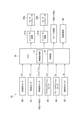
- FIG. 2 is a block diagram showing an electrical configuration of the vehicle of the embodiment.
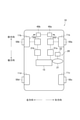
- FIG. 3 is a diagram schematically showing the force acting on the wheels when the vehicle turns.
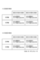
- 4 (A) and 4 (B) show the directions of the respective forces of the motor generator and the tire when the vehicle turns to the left and the directions of the respective forces of the motor generator and the tire when the vehicle turns to the right. It is a chart which shows.
- FIG. 5 is a flowchart showing a procedure of processing executed by the ECU of the embodiment.
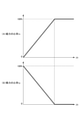
- FIG. 6 is a map showing the relationship between the steering angular velocity ⁇ s of the steering wheel and the target response speed Jc used by the ECU of the embodiment.
- FIG. 7 (A) and 7 (B) are a map showing the relationship between the target response speed Jc and the vertical force ratio rx used by the ECU of the embodiment, and the relationship between the target response speed Jc and the lateral force ratio ry. It is a map showing.
- FIG. 8 is a block diagram showing a schematic configuration of a vehicle of another embodiment.
- FIG. 9 is a block diagram showing a schematic configuration of a vehicle of another embodiment.
- the vehicle 10 of the present embodiment includes a steering device 20, inverter devices 31a and 31b, motor generators 32a and 32b, a steering device 40, and brake devices 50a to 50d. There is.
- the steering device 20 and the steering device 40 constitute a so-called by-wire type steering system in which the steering wheel 21 operated by the driver and the wheels 11a and 11b are not mechanically connected.
- the steering device 20 includes a steering wheel 21 and a steering angle sensor 22.
- the steering angle sensor 22 detects the steering angle ⁇ s, which is the rotation angle of the steering wheel 21, and outputs a signal corresponding to the detected steering angle ⁇ s.
- the steering device 40 changes the steering angles of the wheels 11a and 11b based on the steering angle ⁇ s detected by the steering angle sensor 22.
- the steering device 40 controls the steering angles of the wheels 11a and 11b to the same angle, but the steering device 40 describes the wheels 11a and 11b.
- Each steering angle may be controllable to a different value.
- the inverter devices 31a and 31b convert the DC power supplied from the battery 15 mounted on the vehicle 10 into three-phase AC power, and supply the converted three-phase AC power to the motor generators 32a and 32b, respectively.
- the motor generators 32a and 32b operate as electric motors when the vehicle 10 is accelerating. When operating as an electric motor, the motor generators 32a and 32b are driven based on the three-phase AC power supplied from the inverter devices 31a and 31b. The driving force of the motor generators 32a and 32b is transmitted to the wheels 11a and 11b, respectively, so that the wheels 11a and 11b rotate and the vehicle 10 accelerates.
- the motor generators 32a and 32b can operate as a generator when the vehicle 10 is decelerated.
- the motor generators 32a and 32b operate as a generator, they generate electricity by regenerative operation. Braking force is applied to the wheels 11a and 11b by the regenerative operation of the motor generators 32a and 32b, respectively.
- the three-phase AC power generated by the regenerative operation of the motor generators 32a and 32b is converted into DC power by the inverter devices 31a and 31b and charged to the battery 15.
- the motor generator 32a corresponds to the first electric motor
- the motor generator 32b corresponds to the second electric motor.
- the right front wheel 11a and the left front wheel 11b function as driving wheels
- the right rear wheel 11c and the left rear wheel 11d function as driven wheels.
- the right front wheel 11a and the left front wheel 11b are collectively referred to as "driving wheels 11a and 11b".
- the right front wheel 11a corresponds to the right drive wheel
- the left front wheel 11b corresponds to the left drive wheel.
- the front-rear direction of the vehicle 10 is referred to as "Xc direction”, and the lateral direction of the vehicle 10 is referred to as “Yc direction”.
- the traveling direction is referred to as "Xc1 direction”
- the backward direction is referred to as "Xc2 direction”.
- the lateral Yc of the vehicle 10 the right direction is referred to as “Yc1 direction” and the left direction is referred to as "Yc2 direction”.
- Brake devices 50a to 50d are provided on the wheels 11a to 11d of the vehicle 10, respectively.
- the brake devices 50a to 50d are friction brake devices that apply a braking force to the wheels 11a to 11d by, for example, applying a frictional force to a rotating body that rotates integrally with the wheels 11a to 11d.
- the vehicle 10 includes an acceleration sensor 60, a vehicle speed sensor 61, wheel speed sensors 62a to 62d, an accelerator position sensor 63, a brake position sensor 64, and an ECU (Electronic Control Unit) 70. Is further equipped.
- the acceleration sensor 60 detects the acceleration Ac of the vehicle 10 and outputs a signal corresponding to the detected acceleration Ac to the ECU 70.
- the vehicle speed sensor 61 detects the vehicle speed Vc, which is the traveling speed of the vehicle 10, and outputs a signal corresponding to the detected vehicle speed Vc to the ECU 70.
- the wheel speed sensors 62a to 62d detect the wheel speeds ⁇ wa to ⁇ wd, which are the rotational speeds of the wheels 11a to 11d of the vehicle 10, and output signals corresponding to the detected wheel speeds ⁇ wa to ⁇ wd to the ECU 70.
- the accelerator position sensor 63 detects the accelerator position Pa, which is the operation position of the accelerator pedal of the vehicle 10, and outputs a signal corresponding to the detected accelerator position Pa to the ECU 70.
- the brake position sensor 64 detects the brake operation information Ib indicating whether or not the brake pedal of the vehicle 10 is depressed, and outputs a signal corresponding to the detected brake operation information Ib to the ECU 70.
- the ECU 70 is mainly composed of a microcomputer having a CPU, a memory, and the like.
- the ECU 70 corresponds to a control device.
- the ECU 70 comprehensively controls the vehicle 10 by executing a program stored in advance in the memory.
- the ECU 70 incorporates the output signals of the steering angle sensor 22 in addition to the output signals of the sensors 60, 61, 62a to 62d, 63, 64 described above. Based on these output signals, the ECU 70 determines the acceleration Ac of the vehicle 10, the vehicle speed Vc, the wheel speeds ⁇ wa to ⁇ wd of each wheel 11a to 11d, the accelerator position Pa, the brake operation information Ib, the steering angle ⁇ s of the steering wheel 21, and the like. Get information.
- the ECU 70 controls the vehicle travel control to accelerate or decelerate the vehicle 10 by controlling the output torques of the motor generators 32a and 32b based on the vehicle speed Vc and the accelerator position Pa detected by the vehicle speed sensor 61 and the accelerator position sensor 63, respectively. To execute. Specifically, the ECU 70 maps the target torques Ta * and Tb *, which are the target values of the torques to be applied from the motor generators 32a and 32b to the drive wheels 11a and 11b, respectively, based on the vehicle speed Vc and the accelerator position Pa. Calculate using a calculation formula or the like.
- the ECU 70 calculates the energization control value to be supplied from the inverter devices 31a and 31b to the motor generators 32a and 32b based on the target torques Ta * and Tb *, and also calculates the energization control value to be supplied to the motor generators 32a and 32b, and the inverter device is based on the calculated energization control value. It controls 31a and 31b. As a result, electric power corresponding to the energization control value is supplied from the inverter devices 31a and 31b to the motor generators 32a and 32b, and the actual output torque of the motor generators 32a and 32b is controlled to be the target torques Ta * and Tb *. Will be done.
- the ECU 70 executes braking control for controlling the braking force of the vehicle 10 by controlling the brake devices 50a to 50d based on the brake operation information Ib detected by the brake position sensor 64. Further, the ECU 70 executes turning control for turning the vehicle 10 by controlling the steering device 40 based on the steering angle ⁇ s of the steering wheel 21 detected by the steering angle sensor 22. Specifically, the ECU 70 calculates the target steering angle ⁇ w *, which is the target value of the steering angles ⁇ w of the drive wheels 11a and 11b, based on the steering angle ⁇ s and the like, using a map, an arithmetic formula, or the like. Then, the ECU 70 controls the steering device 40 so that the actual steering angle ⁇ w of the drive wheels 11a and 11b becomes the target steering angle ⁇ w *.
- the ECU 70 of the present embodiment not only changes the steering angle ⁇ w of the driving wheels 11a and 11b by the steering device 40, but also drives the driving force or the driving force from the motor generators 32a and 32b to the driving wheels 11a and 11b. By applying a braking force, the turning performance of the vehicle 10 is improved.
- FIG. 3 the force applied to the tire Ta of the right front wheel 11a when the vehicle 10 is turning to the left is indicated by the arrow Fa10, and the force applied to the tire Tb of the left front wheel 11b is indicated by the arrow Fb10. It is a thing.
- the center point of the contact patch of the right tire Ta is indicated by “Cta”, and the center point of the contact patch of the left tire Tb is indicated by “Ctb”.
- the longitudinal axis of each tire Ta and Tb is indicated by "Xt”
- the lateral axis of each tire Ta and Tb is indicated by "Yt”.
- the turning center axis of the vehicle 10 is indicated by "Cc”.
- the turning center axis Cc of the vehicle 10 is parallel to the vertical direction of the vehicle 10 and corresponds to an axis line passing through the center of gravity of the vehicle 10.
- the steering device 40 turns the right front wheel 11a and the left front wheel 11b to the left in order to turn the vehicle 10 to the left. Steer. As a result, as shown in FIG. 3, a force Fa10 parallel to the tire lateral direction Yt is applied to the right tire Ta, and a force Fb10 parallel to the tire lateral direction Yt is applied to the left tire Tb. To.
- the direction of the effective turning force which is the force contributing to the turning of the vehicle 10
- the direction of the effective turning force is the reference. It is the direction of the outer product between the direction in which the line ma10 extends and the vertical direction of the vehicle 10, which is the direction of the grip force of the right tire Ta. That is, assuming that the direction orthogonal to the reference line ma10 is "ma11" as shown in FIG. 3, the direction of the effective turning force in the right tire Ta is the direction parallel to the axis ma11.
- the direction of the effective turning force in the left tire Tb is the direction parallel to the axis line mb11.
- the effective turning force of the tires Ta and Tb is changed from “FEa10, FEb10" to "FEa11, FEb11".
- the effective turning force of the right tire Ta is changed from “FEa10” to "FEa11” by simply changing the steering angle of the right front wheel 11a, the lateral force of the right tire Ta changes from “Fa10” to "Fa10". It is necessary to steer the right front wheel 11a so as to change to "Fa 11".
- the vertical force Fa12 to be applied to the right tire Ta is a driving force that is a force in the direction of accelerating the vehicle 10.
- the vertical force Fb12 to be applied to the right tire Ta is a braking force which is a force in the direction of decelerating the vehicle 10.
- the driving force and braking force to be applied to the tires Ta and Tb can be realized by changing the output torque of the motor generators 32a and 32b. If the method of changing the effective turning force by changing the output torques of the motor generators 32a and 32b in this way is used, the turning responsiveness is improved as compared with the method of steering the right front wheel 11a and the left front wheel 11b. It is possible.
- the tires Ta and Tb are shown in FIG. It is also possible to apply the forces Fa13 and Fb13, respectively. By applying such forces Fa13 and Fb13 to the tires Ta and Tb, the responsiveness of turning can be changed.
- FIG. 4A shows the direction of the output torque of the motor generators 32a and 32b and the direction of the tire lateral force with respect to the case where the turning force of the vehicle 10 is strengthened and the case where the turning force is weakened when the vehicle 10 is turning to the left. It shows how to set each of the above.
- FIG. 4B shows the direction of the output torque of the motor generators 32a and 32b and the side of the tire with respect to the case where the turning force of the vehicle 10 is strengthened and the case where the turning force is weakened when the vehicle 10 is turning to the right. It shows how to set each direction of force.
- the ECU 70 of the present embodiment controls the motor generators 32a and 32b and the steering device 40 so that the turning response of the vehicle 10 becomes faster when the driver's steering wheel 21 is operated quickly. do.
- the ECU 70 controls the motor generators 32a and 32b and the steering device 40 so that the turning responsiveness of the vehicle 10 becomes slow.
- the ECU 70 includes an information acquisition unit 71 that acquires steering-related information necessary for executing turning control, and a control unit 72 that controls the motor generators 32a and 32b and the steering device 40. I have.
- the information acquisition unit 71 and the control unit 72 repeatedly execute the process shown in FIG. 5 at a predetermined cycle.
- the information acquisition unit 71 first acquires steering-related information as the process of step S10.
- the steering-related information of the present embodiment includes the steering angle ⁇ s and the steering angular velocity ⁇ s of the steering wheel 21.
- the information acquisition unit 71 acquires information on the steering angle ⁇ s based on the output signal of the steering angle sensor 22. Further, the information acquisition unit 71 acquires information on the steering angular velocity ⁇ s by calculating the amount of change in the steering angle ⁇ s per unit time, in other words, by calculating the differential value of the steering angle ⁇ s.
- the steering angle ⁇ s represents the rotation angle to the right from the neutral position of the steering wheel 21 as a positive value, with the rotation angle when the steering wheel 21 is in the neutral position as “0 °”, and is neutral of the steering wheel 21.
- the rotation angle to the left from the position is represented by a negative value.
- the steering angular velocity ⁇ s represents the angular velocity in the right direction of the steering wheel 21 as a positive value, and represents the angular velocity in the left direction of the steering wheel as a negative value.
- the control unit 72 determines whether or not the steering angle ⁇ s is out of the predetermined range as the process of step S11 following step S10.
- the predetermined range is determined in advance by an experiment or the like so that it can be determined whether or not the vehicle 10 is turning, and is stored in the ROM of the ECU 70.
- the control unit 72 determines that the vehicle 10 is not turning when a negative determination is made in the process of step S11, that is, when the steering angle ⁇ s is within a predetermined range, and is shown in FIG. Processing is temporarily terminated.
- the control unit 72 determines that the vehicle 10 is turning, and steps S12, The turning control, which is the process after S13, is executed.
- the control unit 72 calculates the target turning force FE, which is the target value of the turning force of the vehicle 10, as the process of step S12.
- a map showing the relationship between the steering angle ⁇ s and the target turning force FE is created in advance by an experiment or the like and stored in the ROM of the ECU 70.
- the target turning force FE is set to be a positive value.
- the direction of the effective turning force in the tires Ta and Tb is the direction in which the vehicle 10 is turned to the right, that is, the directions FEa12 and FEb12 shown by the two-dot chain line in FIG. Indicates that.
- the target turning force FE when the steering angle ⁇ s is a negative value, that is, when the steering wheel 21 is operated to the left, the target turning force FE is set to be a negative value.
- the direction of the effective turning force in the tires Ta and Tb is the direction in which the vehicle 10 is turned to the left, that is, the directions FEa11 and FEb11 shown by the solid line in FIG. Show that.
- the control unit 72 calculates the target response speed Jc of the vehicle 10 as the process of step S13.
- the target response speed Jc indicates a target value of the response speed when the turning force of the vehicle is changed to the target turning force FE, and is a yaw angle which is a rotation angle of the vehicle 10 with the turning center axis Cc as the central axis.
- a map showing the relationship between the steering angular velocity ⁇ s of the steering wheel 21 and the target response speed Jc is created in advance and stored in the ROM of the ECU 70. In this map, the larger the absolute value of the steering angular velocity ⁇ s of the steering wheel 21, the larger the target response speed Jc is set.
- a map showing the relationship between the steering angular velocity ⁇ s of the steering wheel 21 and the target response speed Jc is created, for example, as shown in FIG.
- the control unit 72 calculates the target response speed Jc from the steering angular velocity ⁇ s obtained in the process of step S10.
- the control unit 72 calculates the reference vertical forces FBXa, FBXb and the reference lateral forces FBYa, FBYb of each tire Ta, Tb as the processing of the step S14 following the steps S12 and S13.
- the reference lateral forces FBYa and FBYb of each tire Ta and Tb are additionally added to each tire Ta and Tb in order to obtain the target turning force FE when the vehicle 10 is turned only by steering the right front wheel 11a and the left front wheel 11b. It is a lateral force that needs to be applied.
- the resultant force of the effective turning force of the reference lateral force FBYa and the effective turning force of the reference lateral force FBYb is the target turning force FE.
- FIG. 1 the model shown in FIG.
- the lateral forces Fa11 and Fb11 of the tires Ta and Tb correspond to the reference lateral forces FBYa and FBYb, respectively.
- a map showing the relationship between the reference lateral forces FBYa and FBYb and the target turning force FE is obtained in advance by an experiment or the like, and is stored in the ROM of the ECU 70.
- the ECU 70 calculates the reference lateral forces FBYa and FBYb from the target turning force FE by using the map stored in the ROM.
- the reference lateral forces FBYa and FBYb represent the direction of the force acting to the right on each tire Ta and Tb as a positive value, and the direction of the force acting to the left on each tire Ta and Tb. It is represented by a negative value.
- the reference vertical forces FBXa and FBXb of the tires Ta and Tb are used to obtain the target turning force FE when the vehicle 10 is turned only by applying the braking force or the driving force to the tires Ta and Tb. It is a braking force or a driving force that needs to be additionally applied to Tb.
- the resultant force of the effective turning force of the reference vertical force FBXa and the effective turning force of the reference vertical force FBXb is the target turning force FE.
- the vertical forces Fa12 and Fb12 of the tires Ta and Tb correspond to the reference vertical forces FBXa and FBXb, respectively.
- a map showing the relationship between the reference vertical forces FBXa and FBXb and the target turning force FE is obtained in advance by an experiment or the like, and is stored in the ROM of the ECU 70.
- the ECU 70 calculates the reference vertical forces FBXa and FBXb from the target turning force FE by using the map stored in the ROM.
- the reference vertical forces FBXa and FBXb represent the driving force, which is the force in the direction of accelerating the vehicle 10, as a positive value, and the braking force, which is the force in the direction of decelerating the vehicle 10, as a negative value. ..
- the control unit 72 has the ratio rx of the vertical force to be actually applied to the tires Ta and Tb with respect to the reference vertical forces FBXa and FBXb as the processing of the step S15 following the step S14, and The ratio ry of the lateral force to be applied to each tire Ta and Tb with respect to the reference lateral force FBYa and FBYb is calculated. Specifically, the control unit 72 calculates the vertical force ratio rx and the lateral force ratio ry from the target response speed Jc obtained in the process of step S13 based on the map. In this map, the faster the target response speed Jc, the larger the vertical force ratio rx and the smaller the lateral force ratio ry.
- the ratios rx and ry are set, for example, in the range of "0 [%]" to "100 [%]".
- the force acting on the right tire Ta is the resultant force of the reference vertical force FBXa multiplied by the ratio rx and the reference lateral force FBYa multiplied by the ratio ry.
- the force acting on the left tire Tb is the resultant force of the reference vertical force FBXb multiplied by the ratio rx and the reference lateral force FBYb multiplied by the ratio ry.
- the turning force of the vehicle 10 is defined by the resultant force of the effective turning force corresponding to the force acting on the right tire Ta and the effective turning force corresponding to the force acting on the left tire Tb.
- the ratios rx and ry are set so that the turning force of the vehicle 10 defined in this way becomes the target turning force FE.
- a map for calculating the ratios rx and ry for example, a map as shown in FIGS. 7A and 7B is used. As shown in FIGS. 7A and 7B, the ratios rx and ry are set so that the total value thereof is, for example, "100 [%]". The total value of the ratios rx and ry may be set to a value different from "100 [%]".
- the control unit 72 executes the processes of steps S16 to S19 following step S15.
- the control unit 72 calculates the target torques TMa * and TMb *, which are the target values of the torque to be additionally output from the motor generators 32a and 32b.
- the control unit 72 multiplies the reference vertical force FBXa of the right tire Ta obtained in the process of step S14 by the ratio rx of the vertical force obtained in the process of step S15 to obtain the right tire Ta.
- the target right-side vertical force FXa * which is the target value of the vertical force to be additionally applied to, is calculated.
- the control unit 72 uses a calculation formula or the like from the target right vertical force FXa * to obtain the target value TMa * of the output torque of the motor generator 32a that can additionally apply the target right vertical force FXa * to the right tire Ta. And calculate. Similarly, the control unit 72 calculates the target left vertical force FXb * based on the reference vertical force FBXb of the left tire Tb and the ratio rx of the vertical force, and outputs the motor generator 32b based on the target left vertical force FXb *. Calculate the torque target value TMb *.
- the control unit 72 executes torque control of the motor generators 32a and 32b as a process of step S17 following step S16. Specifically, the control unit 72 controls the motor generators 32a and 32b so that the target torques TMa * and TMb * obtained in the process of step S16 are output.
- the control unit 72 calculates the target steering angles ⁇ a * and ⁇ b *, which are the target values of the steering angles at which the right front wheel 11a and the left front wheel 11b should be additionally steered, as the process of step S18. Specifically, the control unit 72 multiplies the reference lateral force FBYa of the right tire Ta obtained in the process of step S14 by the ratio ry of the lateral force obtained in the process of step S15, so that the right tire Ta The target right lateral force FYa *, which is the target value of the lateral force to be additionally applied to, is calculated.
- the control unit 72 sets a target value ⁇ a * of the steering angle of the right front wheel 11a capable of applying the target right lateral force FYa * to the right tire Ta, and maps, a calculation formula, etc. from the target right lateral force FYa *. Calculate using.
- the control unit 72 calculates the target value ⁇ b * of the steering angle of the left front wheel 11b based on the reference lateral force FBYb of the left tire Tb and the ratio ry of the lateral force.
- the control unit 72 executes the steering angle control of the drive wheels 11a and 11b as the process of step S19 following step S18. Specifically, the control unit 72 controls the steering device 40 so that the wheels 11a and 11b are steered only by the target steering angles ⁇ a * and ⁇ b * obtained in the process of step S18.
- the control unit 72 cooperatively drives the motor generators 32a and 32b and the steering device 40 based on the steering-related information acquired by the information acquisition unit 71, whereby the vehicle 10 is driven.
- a turning control is executed to control the force to be applied to the tires of the drive wheels 11a and 11b in order to turn.
- the driver operates the steering wheel 21 quickly when he / she wants to turn the vehicle 10 fast, and operates the steering wheel 21 slowly when he / she wants to turn the vehicle 10 slowly. Therefore, the steering angular velocity ⁇ s of the steering wheel 21 is a parameter that reflects the driver's willingness to turn.
- the turning responsiveness of the vehicle 10 is changed. be able to. Therefore, like the ECU 70 of the present embodiment, by changing the power of the motor generators 32a and 32b based on the steering angular velocity ⁇ s of the steering wheel 21, it is possible to improve the turning responsiveness of the vehicle and the driver. Since it is possible to realize the turning of the vehicle reflecting the intention of the above, it is possible to reduce the discomfort of the driver.
- the control unit 72 calculates the target turning force FE based on the steering angle ⁇ s of the steering wheel 21, and calculates the target response speed Jc based on the steering angular velocity ⁇ s of the steering wheel 21. Then, the control unit 72 controls the motor generators 32a and 32b so that the braking force or the driving force applied to the tires Ta and Tb by the control of the motor generators 32a and 32b becomes larger as the target response speed Jc becomes faster. Further, the control unit 72 determines the resultant force between the tire longitudinal force applied to the tires Ta and Tb by the control of the motor generators 32a and 32b and the tire lateral force applied to the tires Ta and Tb by the control of the steering device 40. The steering device 40 is controlled so that the corresponding turning force becomes the target turning force FE. According to this configuration, it is possible to realize the responsiveness of turning according to the driver's intention while turning the vehicle 10 according to the steering angle ⁇ s.
- the control unit 72 makes the torque transmitted from the motor generator 32a to the right front wheel 11a different from the torque transmitted from the motor generator 32b to the left front wheel 11b. To reverse those torques. According to this configuration, it becomes easier to turn the vehicle 10, so that the responsiveness of turning can be improved.
- the control unit 72 executes turning control, which is a process after steps S12 and S13 shown in FIG. 3, based on the steering angle ⁇ s being out of the predetermined range. According to this configuration, when the vehicle 10 is turning, the responsiveness of the turning can be improved.
- the above embodiment can also be carried out in the following embodiments.
- the ECU 70 detects an abnormality in either one of the motor generators 32a and 32b, the ECU 70 does not have to execute the turning control shown in FIG. If an abnormality occurs in either one of the motor generators 32a and 32b, the control for retracting and traveling the vehicle 10 may be executed. If the turning control shown in FIG. 5 is executed while such evacuation control is being executed, the behavior of the vehicle 10 may become unstable due to the interference of these controls. Therefore, if the turning control shown in FIG. 5 is not executed when an abnormality occurs in either one of the motor generators 32a and 32b, the vehicle 10 can be evacuated and traveled more accurately.
- the vehicle 10 is controlled by a motor generator 32c that applies braking force and driving force to the right rear wheel 11c, an inverter device 31c that supplies electric power to the motor generator 32c, and a left rear wheel 11d.
- a motor generator 32d that imparts power and driving force, and an inverter device 31d that supplies electric power to the motor generator 32d may be further provided.
- the vehicle 10 may separately include a steering device 40a for steering the right front wheel 11a and a steering device 40b for steering the left front wheel 11b.
- the control unit 72 may use the steering angular acceleration or the steering angular jerk of the steering wheel 21 instead of the steering angular velocity ⁇ s of the steering wheel 21 as parameters used for calculating the target response speed Jc.
- the steering angle jerk is the steering angle acceleration.
- the control unit 72 may calculate the target response speed Jc based on at least one of the steering angular velocity ⁇ s, the steering angular acceleration, and the steering angular jerk of the steering wheel 21.
- the ECU 70 and its control methods described herein are provided by configuring a processor and memory programmed to perform one or more functions embodied by a computer program. It may be realized by a dedicated computer.
- the ECU 70 and its control method described in the present disclosure may be realized by a dedicated computer provided by configuring a processor including one or more dedicated hardware logic circuits.
- the ECU 70 and its control method described in the present disclosure are configured by a combination of a processor and memory programmed to perform one or more functions and a processor including one or more hardware logic circuits. It may be realized by one or more dedicated computers.
- the computer program may be stored on a computer-readable non-transitional tangible recording medium as an instruction executed by the computer.
- the dedicated hardware logic circuit and the hardware logic circuit may be realized by a digital circuit including a plurality of logic circuits or an analog circuit.
Landscapes
- Engineering & Computer Science (AREA)
- Transportation (AREA)
- Mechanical Engineering (AREA)
- Chemical & Material Sciences (AREA)
- Combustion & Propulsion (AREA)
- Automation & Control Theory (AREA)
- Power Engineering (AREA)
- Steering Control In Accordance With Driving Conditions (AREA)
- Control Of Driving Devices And Active Controlling Of Vehicle (AREA)
- Electric Propulsion And Braking For Vehicles (AREA)
Abstract
制御装置(70)は、制御部(72)と、情報取得部(71)と、を備える。制御部は、車輪を転舵させる転舵装置(40)及び電動モータを制御する。情報取得部は、車両のステアリングホイールの操舵角速度、操舵角加速度、及び操舵角躍度の少なくとも一つ、並びにステアリングホイールの操舵角を含む操舵関連情報を取得する。制御部が操舵関連情報に基づいて電動モータ及び転舵装置を協調して駆動させることにより、車両を旋回させるために車輪のタイヤに付与すべき力を制御する旋回制御を実行する。
Description
本出願は、2020年7月20日に出願された日本国特許出願2020-123784号に基づくものであって、その優先権の利益を主張するものであり、その特許出願の全ての内容が、参照により本明細書に組み込まれる。
本開示は、車両の制御装置に関する。
従来、下記の特許文献1に記載の車両の制御装置がある。特許文献1に記載の車両の制御装置は、ヨー加速度算出部と、駆動力制御部とを備えている。ヨー加速度算出部は、車両のヨー加速度を取得する。駆動力制御部は、ヨー加速度算出部により取得されたヨー加速度に応じて、車両の動力源であるモータの駆動力を低減させる。駆動力制御部は、ヨー加速度が増大するほど、モータの駆動力低減量を増大させ、且つこの増大量の増加割合を低減させて所定の上限値に漸近させるように制御する。この構成によれば、車両の操舵が開始されて車両のヨー加速度が増大し始めた際に、ヨー加速度が増大するほど、モータの駆動力低減量の増大割合が低減するため、カーブ走行中に車両に発生する減速度が過大になり難くなる。よって、車両の旋回時における運転者の操作が自然で安定したものとなるように車両の挙動を制御することができる。
車両を旋回させる方法としては、車両の車輪を転舵させることにより車両を転舵させる方法と、特許文献1に記載の制御装置のようにモータから車輪に伝達されるトルクを増減させる方法とがある。後者の方法の方が、前者の方法よりも応答性が早いため、より早期に車両を旋回させることが可能である。しかしながら、特許文献1に記載の制御装置のように、モータから車輪に伝達されるトルクのみを増減させて車両を旋回させると、その際の車両の挙動には運転者の意志が反映され難くなるため、運転者が違和感を覚える可能性がある。
本開示の目的は、運転者の違和感を軽減しつつ、旋回の応答性を向上させることが可能な車両の制御装置を提供することにある。
本開示の一態様による制御装置は、電動モータから車輪にトルクを伝達することにより走行する車両を制御する。制御装置は、制御部と、情報取得部と、を備える。制御部は、車輪を転舵させる転舵装置及び電動モータを制御する。情報取得部は、車両のステアリングホイールの操舵角速度、操舵角加速度、及び操舵角躍度の少なくとも一つ、並びにステアリングホイールの操舵角を含む操舵関連情報を取得する。制御部が操舵関連情報に基づいて電動モータ及び転舵装置を協調して駆動させることにより、車両を旋回させるために車輪のタイヤに付与すべき力を制御する旋回制御を実行する。
運転者は、例えば車両を速く旋回させたい場合にはステアリングホイールを速く操作し、車両を遅く旋回させたい場合にはステアリングホイールを遅く操作する。したがって、ステアリングホイールの操舵角速度、操舵角加速度、及び操舵角躍度の少なくとも一つは、運転者の旋回の意志が反映されたパラメータである。また、車両を転舵させる際に転舵装置により車輪を転舵させるだけでなく電動モータの動力を変化させれば、車両の旋回の応答性を向上させることが可能である。したがって、上記構成のように、車両を旋回させる際にステアリングホイールの操舵角速度、操舵角加速度、及び操舵角躍度の少なくとも一つに基づいて電動モータの動力を変化させることにより、車両の旋回の応答性を向上させることができるとともに、運転者の意図が反映された車両の旋回を実現することができるため、運転者の違和感を軽減することが可能である。
以下、車両の制御装置の一実施形態について図面を参照しながら説明する。説明の理解を容易にするため、各図面において同一の構成要素に対しては可能な限り同一の符号を付して、重複する説明は省略する。
はじめに、本実施形態の制御装置が搭載される車両の概略構成について説明する。図1に示されるように、本実施形態の車両10は、操舵装置20と、インバータ装置31a,31bと、モータジェネレータ32a,32bと、転舵装置40と、ブレーキ装置50a~50dとを備えている。
はじめに、本実施形態の制御装置が搭載される車両の概略構成について説明する。図1に示されるように、本実施形態の車両10は、操舵装置20と、インバータ装置31a,31bと、モータジェネレータ32a,32bと、転舵装置40と、ブレーキ装置50a~50dとを備えている。
操舵装置20及び転舵装置40は、運転者により操作されるステアリングホイール21と車輪11a,11bとが機械的に連結されていない、いわゆるバイワイヤ式のステアリングシステムを構成している。操舵装置20はステアリングホイール21と操舵角センサ22とを備えている。操舵角センサ22は、ステアリングホイール21の回転角度である操舵角θsを検出するとともに、検出された操舵角θsに応じた信号を出力する。転舵装置40は、操舵角センサ22により検出される操舵角θsに基づいて車輪11a,11bのそれぞれの転舵角を変化させる。
なお、本実施形態では、簡単のために転舵装置40が車輪11a,11bのそれぞれの転舵角を同一の角度に制御する場合について説明するが、転舵装置40は、車輪11a,11bのそれぞれの転舵角を異なる値に制御可能なものであってもよい。
インバータ装置31a,31bは、車両10に搭載されるバッテリ15から供給される直流電力を三相交流電力に変換するとともに、変換した三相交流電力をモータジェネレータ32a,32bにそれぞれ供給する。
インバータ装置31a,31bは、車両10に搭載されるバッテリ15から供給される直流電力を三相交流電力に変換するとともに、変換した三相交流電力をモータジェネレータ32a,32bにそれぞれ供給する。
モータジェネレータ32a,32bは車両10の加速走行時に電動機として動作する。モータジェネレータ32a,32bは、電動機として動作する場合、インバータ装置31a,31bから供給される三相交流電力に基づいて駆動する。モータジェネレータ32a,32bの駆動力が車輪11a,11bにそれぞれ伝達されることにより車輪11a,11bが回転して車両10が加速走行する。
また、モータジェネレータ32a,32bは車両10の減速走行時に発電機として動作することが可能である。モータジェネレータ32a,32bは、発電機として動作する場合、回生動作することにより発電する。このモータジェネレータ32a,32bの回生動作により車輪11a,11bに制動力がそれぞれ付与される。モータジェネレータ32a,32bの回生動作により発電される三相交流電力はインバータ装置31a,31bにより直流電力に変換されてバッテリ15に充電される。本実施形態では、モータジェネレータ32aが第1電動モータに相当し、モータジェネレータ32bが第2電動モータに相当する。
このように、車両10では、右前輪11a及び左前輪11bが駆動輪として機能し、右後輪11c及び左後輪11dが従動輪として機能する。以下では、右前輪11a及び左前輪11bをまとめて「駆動輪11a,11b」とも称する。本実施形態では、右前輪11aが右駆動輪に相当し、左前輪11bが左駆動輪に相当する。
また、以下では、車両10の前後方向を「Xc方向」と称し、車両10の横方向を「Yc方向」と称する。さらに、車両10の前後方向Xcのうち、進行方向を「Xc1方向」と称し、後退方向を「Xc2方向」と称する。また、車両10の横方向Ycのうち、右方向を「Yc1方向」と称し、左方向を「Yc2方向」と称する。
ブレーキ装置50a~50dは車両10の車輪11a~11dにそれぞれ設けられている。ブレーキ装置50a~50dは、例えば各車輪11a~11dと一体となって回転する回転体に摩擦力を付与することにより各車輪11a~11dに制動力を付与する摩擦ブレーキ装置である。
次に、図2を参照して、車両10の電気的な構成について説明する。
図2に示されるように、車両10は、加速度センサ60と、車速センサ61と、車輪速センサ62a~62dと、アクセルポジションセンサ63と、ブレーキポジションセンサ64と、ECU(Electronic Control Unit)70とを更に備えている。
図2に示されるように、車両10は、加速度センサ60と、車速センサ61と、車輪速センサ62a~62dと、アクセルポジションセンサ63と、ブレーキポジションセンサ64と、ECU(Electronic Control Unit)70とを更に備えている。
加速度センサ60は、車両10の加速度Acを検出するとともに、検出された加速度Acに応じた信号をECU70に出力する。車速センサ61は、車両10の走行速度である車速Vcを検出するとともに、検出された車速Vcに応じた信号をECU70に出力する。車輪速センサ62a~62dは、車両10の車輪11a~11dの回転速度である車輪速ωwa~ωwdをそれぞれ検出するとともに、検出された車輪速ωwa~ωwdに応じた信号をECU70に出力する。アクセルポジションセンサ63は、車両10のアクセルペダルの操作位置であるアクセルポジションPaを検出するとともに、検出されたアクセルポジションPaに応じた信号をECU70に出力する。ブレーキポジションセンサ64は、車両10のブレーキペダルが踏み込まれたか否かを示すブレーキ操作情報Ibを検出するとともに、検出されたブレーキ操作情報Ibに応じた信号をECU70に出力する。
ECU70は、CPUやメモリ等を有するマイクロコンピュータを中心に構成されている。本実施形態では、ECU70が制御装置に相当する。ECU70は、そのメモリに予め記憶されたプログラムを実行することにより車両10を統括的に制御する。
具体的には、ECU70には、上述したセンサ60,61,62a~62d,63,64のそれぞれの出力信号の他、操舵角センサ22の出力信号が取り込まれている。ECU70は、それらの出力信号に基づいて車両10の加速度Ac、車速Vc、各車輪11a~11dの車輪速ωwa~ωwd、アクセルポジションPa、ブレーキ操作情報Ib、及びステアリングホイール21の操舵角θs等の情報を取得する。
具体的には、ECU70には、上述したセンサ60,61,62a~62d,63,64のそれぞれの出力信号の他、操舵角センサ22の出力信号が取り込まれている。ECU70は、それらの出力信号に基づいて車両10の加速度Ac、車速Vc、各車輪11a~11dの車輪速ωwa~ωwd、アクセルポジションPa、ブレーキ操作情報Ib、及びステアリングホイール21の操舵角θs等の情報を取得する。
ECU70は、例えば車速センサ61及びアクセルポジションセンサ63によりそれぞれ検出される車速Vc及びアクセルポジションPaに基づいてモータジェネレータ32a,32bの出力トルクを制御することにより、車両10を加速又は減速させる車両走行制御を実行する。具体的には、ECU70は、車速Vc及びアクセルポジションPaに基づいて、モータジェネレータ32a,32bから駆動輪11a,11bにそれぞれ付与すべきトルクの目標値である目標トルクTa*,Tb*をマップや演算式等を用いて演算する。そして、ECU70は、目標トルクTa*,Tb*に基づいて、インバータ装置31a,31bからモータジェネレータ32a,32bに供給すべき通電制御値を演算するとともに、演算された通電制御値に基づいてインバータ装置31a,31bを制御する。これにより、通電制御値に応じた電力がインバータ装置31a,31bからモータジェネレータ32a,32bに供給されて、モータジェネレータ32a,32bの実際の出力トルクが目標トルクTa*,Tb*となるように制御される。
また、ECU70は、ブレーキポジションセンサ64により検出されるブレーキ操作情報Ibに基づいてブレーキ装置50a~50dを制御することにより車両10の制動力を制御する制動制御を実行する。
さらに、ECU70は、操舵角センサ22により検出されるステアリングホイール21の操舵角θs等に基づいて転舵装置40を制御することにより車両10を旋回させる旋回制御を実行する。具体的には、ECU70は、操舵角θs等に基づいて、駆動輪11a,11bの転舵角θwの目標値である目標転舵角θw*をマップや演算式等を用いて演算する。そして、ECU70は、駆動輪11a,11bの実際の転舵角θwが目標転舵角θw*となるように転舵装置40を制御する。
さらに、ECU70は、操舵角センサ22により検出されるステアリングホイール21の操舵角θs等に基づいて転舵装置40を制御することにより車両10を旋回させる旋回制御を実行する。具体的には、ECU70は、操舵角θs等に基づいて、駆動輪11a,11bの転舵角θwの目標値である目標転舵角θw*をマップや演算式等を用いて演算する。そして、ECU70は、駆動輪11a,11bの実際の転舵角θwが目標転舵角θw*となるように転舵装置40を制御する。
一方、本実施形態のECU70は、旋回制御において、転舵装置40により駆動輪11a,11bの転舵角θwを変化させるだけでなく、モータジェネレータ32a,32bから駆動輪11a,11bに駆動力又は制動力を付与することにより車両10の旋回性を向上させる。
次に、本実施形態の旋回制御について説明するに先立ち、その原理について先ずは説明する。
図3は、車両10が左方向に旋回している際に右前輪11aのタイヤTaに加わっている力を矢印Fa10で示し、左前輪11bのタイヤTbに加わっている力を矢印Fb10で示したものである。図3では、右側タイヤTaの接地面の中心点が「Cta」で示され、左側タイヤTbの接地面の中心点が「Ctb」で示されている。また、各タイヤTa,Tbの前後方向の軸線が「Xt」で示されるとともに、各タイヤTa,Tbの横方向の軸線が「Yt」で示されている。さらに、車両10の旋回中心軸が「Cc」で示されている。車両10の旋回中心軸Ccは、車両10の上下方向に平行であって、且つ車両10の重心を通る軸線に相当する。
図3は、車両10が左方向に旋回している際に右前輪11aのタイヤTaに加わっている力を矢印Fa10で示し、左前輪11bのタイヤTbに加わっている力を矢印Fb10で示したものである。図3では、右側タイヤTaの接地面の中心点が「Cta」で示され、左側タイヤTbの接地面の中心点が「Ctb」で示されている。また、各タイヤTa,Tbの前後方向の軸線が「Xt」で示されるとともに、各タイヤTa,Tbの横方向の軸線が「Yt」で示されている。さらに、車両10の旋回中心軸が「Cc」で示されている。車両10の旋回中心軸Ccは、車両10の上下方向に平行であって、且つ車両10の重心を通る軸線に相当する。
車両10が直進している際に運転者がステアリングホイール21を左方向に操作したとすると、車両10を左方向に旋回させるべく、転舵装置40が右前輪11a及び左前輪11bを左方向に転舵させる。これにより、図3に示されるように、右側タイヤTaには、タイヤ横方向Ytに平行な力Fa10が付与されるとともに、左側タイヤTbには、タイヤ横方向Ytに平行な力Fb10が付与される。
一方、車両10の旋回中心軸Ccに直交し、且つ右側タイヤTaの接地中心点Ctを通る軸線を基準線ma10とすると、車両10の旋回に寄与する力である実効旋回力の方向は、基準線ma10が延びる方向と、右側タイヤTaのグリップ力の方向である車両10の上下方向との外積の方向となる。すなわち、図3に示されるように基準線ma10に直交する方向を「ma11」とすると、右側タイヤTaにおける実効旋回力の方向は軸線ma11に平行な方向となる。同様に、図3に示されるように左側タイヤTbに対応する基準線b10に直交する方向を「mb11」とすると、左側タイヤTbにおける実効旋回力の方向は軸線mb11に平行な方向となる。
したがって、右側タイヤTaにタイヤ横力Fa10が作用しているとすると、そのタイヤ横力Fa10のうち、軸線ma11に沿った方向の力成分FEa10のみが車両10の旋回に寄与する力となる。同様に、左側タイヤTbのタイヤ横力Fb10のうち、軸線mb11に沿った方向の力成分FEb10のみが車両10の旋回に寄与する力となる。また、これらの力成分FEa10及び力成分FEb10の合力が、車両10に作用する旋回力となる。
このように車両10に左方向の旋回力が付与されている状態で更に車両10の旋回力を強めるために、タイヤTa,Tbにおける実効旋回力を「FEa10,FEb10」から「FEa11,FEb11」に変化させる場合を考える。この場合、単に右前輪11aの転舵角を変化させるだけで右側タイヤTaにおける実効旋回力を「FEa10」から「FEa11」に変化させようとすると、右側タイヤTaにおける横力が「Fa10」から「Fa11」に変化するように右前輪11aを転舵させる必要がある。同様に、左側タイヤTbにおける横力が「Fb10」から「Fb11」に変化するように左前輪11bも転舵させる必要がある。このように、右前輪11a及び左前輪11bの転舵により実効旋回力を変化させようとすると、旋回の応答性が低いことが懸念される。
一方、各タイヤTa,Tbにおける実効旋回力を「FEa10,FEb10」から「FEa11,FEb11」に変化させる方法としては、タイヤTa,Tbに対して、その縦方向Xtに平行な縦力Fa12,Fb12を加えるという方法がある。なお、右側タイヤTaに付与すべき縦力Fa12は、車両10を加速させる方向の力である駆動力である。一方、右側タイヤTaに付与すべき縦力Fb12は、車両10を減速させる方向の力である制動力である。各タイヤTa,Tbに付与すべき駆動力及び制動力は、モータジェネレータ32a,32bの出力トルクを変化させることにより実現可能である。このようにモータジェネレータ32a,32bの出力トルクを変化させることにより実効旋回力を変化させる方法を用いれば、右前輪11a及び左前輪11bを転舵させる方法と比較すると、旋回の応答性を向上させることが可能である。
また、モータジェネレータ32a,32bの出力トルクを変化させる方法と、右前輪11a及び左前輪11bの転舵角を変化させる方法とを組み合わせることにより、タイヤTa,Tbに対して、図3に示される力Fa13,Fb13をそれぞれ付与することも可能である。このような力Fa13,Fb13をタイヤTa,Tbに対して付与することにより、旋回の応答性を変化させることができる。
図4(A)は、車両10が左旋回している場合に車両10の旋回力を強める場合と、旋回力を弱める場合とに関して、モータジェネレータ32a,32bの出力トルクの方向及びタイヤ横力の方向のそれぞれをどのように設定すべきかを示したものである。また、図4(B)は、車両10が右旋回している場合に車両10の旋回力を強める場合と、旋回力を弱める場合とに関して、モータジェネレータ32a,32bの出力トルクの方向及びタイヤ横力の方向のそれぞれをどのように設定すべきかを示したものである。
このように、モータジェネレータ32a,32bの出力トルクを変化させる方法と、転舵装置40により右前輪11a及び左前輪11bの転舵角を変化させる方法とを組み合わせることにより、旋回の応答性を変化させることが可能である。これを利用し、本実施形態のECU70は、運転者のステアリングホイール21の操作が速い場合には、車両10の旋回の応答性が速くなるようにモータジェネレータ32a,32b及び転舵装置40を制御する。一方、ECU70は、運転者のステアリングホイール21の操作が遅い場合には、車両10の旋回の応答性が遅くなるようにモータジェネレータ32a,32b及び転舵装置40を制御する。
次に、車両10の旋回力を変化させる旋回制御を実行するためのECU70の構成について具体的に説明する。
図2に示されるように、ECU70は、旋回制御の実行のために必要な操舵関連情報を取得する情報取得部71と、モータジェネレータ32a,32b及び転舵装置40を制御する制御部72とを備えている。情報取得部71及び制御部72は、図5に示される処理を所定の周期で繰り返し実行する。
図2に示されるように、ECU70は、旋回制御の実行のために必要な操舵関連情報を取得する情報取得部71と、モータジェネレータ32a,32b及び転舵装置40を制御する制御部72とを備えている。情報取得部71及び制御部72は、図5に示される処理を所定の周期で繰り返し実行する。
図5に示されるように、情報取得部71は、まず、ステップS10の処理として、操舵関連情報を取得する。本実施形態の操舵関連情報には、ステアリングホイール21の操舵角θs及び操舵角速度ωsが含まれている。情報取得部71は、操舵角センサ22の出力信号に基づいて操舵角θsの情報を取得する。また、情報取得部71は、単位時間当たりの操舵角θsの変化量を演算することにより、換言すれば操舵角θsの微分値を演算することにより操舵角速度ωsの情報を取得する。なお、操舵角θsは、ステアリングホイール21が中立位置であるときの回転角度を「0°」として、ステアリングホイール21の中立位置から右方向の回転角度を正の値で表し、ステアリングホイール21の中立位置から左方向の回転角度を負の値で表すものである。また、操舵角速度ωsは、ステアリングホイール21の右方向の角速度を正の値で表し、ステアリングホイールの左方向の角速度を負の値で表すものである。
制御部72は、ステップS10に続くステップS11の処理として、操舵角θsが所定範囲から外れているか否かを判断する。所定範囲は、車両10が旋回中であるか否かを判断することができるように予め実験等により求められており、ECU70のROMに記憶されている。制御部72は、ステップS11の処理で否定的な判断を行った場合には、すなわち操舵角θsが所定範囲内である場合には、車両10が旋回中でないと判定して、図5に示される処理を一旦終了する。
制御部72は、ステップS11の処理で肯定的な判断を行った場合には、すなわち操舵角θsが所定範囲から外れている場合には、車両10が旋回中であると判定し、ステップS12,S13以降の処理である旋回制御を実行する。
制御部72は、まず、ステップS12の処理として、車両10の旋回力の目標値である目標旋回力FEを演算する。本実施形態では、操舵角θsと目標旋回力FEとの関係を示すマップが予め実験等により作成されており、ECU70のROMに記憶されている。
制御部72は、まず、ステップS12の処理として、車両10の旋回力の目標値である目標旋回力FEを演算する。本実施形態では、操舵角θsと目標旋回力FEとの関係を示すマップが予め実験等により作成されており、ECU70のROMに記憶されている。
このマップでは、基本的には、操舵角θsの絶対値が大きくなるほど、目標旋回力FEの絶対値が大きくなるように設定されている。また、このマップでは、操舵角θsが正の値である場合、すなわちステアリングホイール21が右方向に操作されている場合には、目標旋回力FEが正の値となるように設定されている。目標旋回力FEが正の値である場合とは、タイヤTa,Tbにおける実効旋回力の方向が、車両10を右方向に旋回させる方向、すなわち図3に二点鎖線で示される方向FEa12,FEb12であることを示す。また、このマップでは、操舵角θsが負の値である場合、すなわちステアリングホイール21が左方向に操作されている場合には、目標旋回力FEが負の値となるように設定されている。目標旋回力FEが負の値である場合とは、タイヤTa,Tbにおける実効旋回力の方向が、車両10を左方向に旋回させる方向、すなわち図3に実線で示される方向FEa11,FEb11であることを示す。
図5に示されるように、制御部72は、ステップS13の処理として、車両10の目標応答速度Jcを演算する。目標応答速度Jcは、車両の旋回力を目標旋回力FEまで変化させる際の応答速度の目標値を示すものであって、旋回中心軸Ccを中心軸とする車両10の回転角度であるヨー角の加加速度に相当する。本実施形態では、ステアリングホイール21の操舵角速度ωsと目標応答速度Jcとの関係を示すマップが予め作成されており、ECU70のROMに記憶されている。このマップでは、ステアリングホイール21の操舵角速度ωsの絶対値が大きくなるほど、目標応答速度Jcがより大きな値に設定されるようになっている。これは、ステアリングホイール21の操舵角速度ωsの絶対値が大きくなるほど、運転者が車両10をより速く旋回させようとしている状況であると考えられるためである。ステアリングホイール21の操舵角速度ωsと目標応答速度Jcとの関係を示すマップは、例えば図6に示されるように作成される。制御部72は、このマップを用いることにより、ステップS10の処理で得られた操舵角速度ωsから目標応答速度Jcを演算する。
図5に示されるように、制御部72は、ステップS12,S13に続くステップS14の処理として、各タイヤTa,Tbの基準縦力FBXa,FBXb及び基準横力FBYa,FBYbを演算する。
各タイヤTa,Tbの基準横力FBYa,FBYbは、右前輪11a及び左前輪11bの転舵のみで車両10を旋回させる場合に、目標旋回力FEを得るために各タイヤTa,Tbに追加で付与する必要のある横力である。基準横力FBYaの実効旋回力及び基準横力FBYbの実効旋回力の合力が目標旋回力FEとなる。図3に示されるモデルでは、各タイヤTa,Tbの横力Fa11,Fb11が基準横力FBYa,FBYbにそれぞれ相当する。本実施形態では、基準横力FBYa,FBYbと目標旋回力FEとの関係を示すマップが予め実験等により求められており、ECU70のROMに記憶されている。ECU70は、ROMに記憶されたマップを用いることにより、目標旋回力FEから基準横力FBYa,FBYbを演算する。なお、基準横力FBYa,FBYbは、各タイヤTa,Tbに対して右方向に作用する力の方向を正の値で表し、各タイヤTa,Tbに対して左方向に作用する力の方向を負の値で表すものである。
各タイヤTa,Tbの基準横力FBYa,FBYbは、右前輪11a及び左前輪11bの転舵のみで車両10を旋回させる場合に、目標旋回力FEを得るために各タイヤTa,Tbに追加で付与する必要のある横力である。基準横力FBYaの実効旋回力及び基準横力FBYbの実効旋回力の合力が目標旋回力FEとなる。図3に示されるモデルでは、各タイヤTa,Tbの横力Fa11,Fb11が基準横力FBYa,FBYbにそれぞれ相当する。本実施形態では、基準横力FBYa,FBYbと目標旋回力FEとの関係を示すマップが予め実験等により求められており、ECU70のROMに記憶されている。ECU70は、ROMに記憶されたマップを用いることにより、目標旋回力FEから基準横力FBYa,FBYbを演算する。なお、基準横力FBYa,FBYbは、各タイヤTa,Tbに対して右方向に作用する力の方向を正の値で表し、各タイヤTa,Tbに対して左方向に作用する力の方向を負の値で表すものである。
各タイヤTa,Tbの基準縦力FBXa,FBXbは、各タイヤTa,Tbへの制動力又は駆動力の付与のみで車両10を旋回させる場合に、目標旋回力FEを得るために各タイヤTa,Tbに追加で付与する必要のある制動力又は駆動力である。基準縦力FBXaの実効旋回力及び基準縦力FBXbの実効旋回力の合力が目標旋回力FEとなる。図3に示されるモデルでは、各タイヤTa,Tbの縦力Fa12,Fb12が基準縦力FBXa,FBXbにそれぞれ相当する。本実施形態では、基準縦力FBXa,FBXbと目標旋回力FEとの関係を示すマップが予め実験等により求められており、ECU70のROMに記憶されている。ECU70は、ROMに記憶されたマップを用いることにより、目標旋回力FEから基準縦力FBXa,FBXbを演算する。なお、基準縦力FBXa,FBXbは、車両10を加速させる方向の力である駆動力を正の値で表し、車両10を減速させる方向の力である制動力を負の値で表すものである。
図5に示されるように、制御部72は、ステップS14に続くステップS15の処理として、基準縦力FBXa,FBXbに対して実際に各タイヤTa,Tbに付与すべき縦力の比率rx、及び基準横力FBYa,FBYbに対して各タイヤTa,Tbに付与すべき横力の比率ryを演算する。具体的には、制御部72は、ステップS13の処理で得られる目標応答速度Jcからマップに基づいて縦力の比率rx及び横力の比率ryを演算する。このマップでは、目標応答速度Jcが速くなるほど、縦力の比率rxが大きくなり、且つ横力の比率ryが小さくなるように設定されている。比率rx,ryは、例えば「0[%]」から「100[%]」の範囲で設定される。
これらの比率rx,ryを用いることにより、右側タイヤTaに作用する力は、基準縦力FBXaに比率rxを乗算した力と、基準横力FBYaに比率ryを乗算した力との合力となる。同様に、左側タイヤTbに作用する力は、基準縦力FBXbに比率rxを乗算した力と、基準横力FBYbに比率ryを乗算した力との合力となる。また、車両10の旋回力は、右側タイヤTaに作用する力に対応した実効旋回力と、左側タイヤTbに作用する力に対応した実効旋回力との合力で定義される。このように定義される車両10の旋回力が目標旋回力FEとなるように各比率rx,ryが設定されている。比率rx,ryを演算するためのマップとしては、例えば図7(A),(B)に示されるようなマップが用いられる。図7(A),(B)に示されるように、比率rx,ryは、例えばそれらの合計値が「100[%]」となるように設定される。なお、比率rx,ryの合計値は、「100[%]」とは異なる値に設定されていてもよい。
図5に示されるように、制御部72は、ステップS15に続いて、ステップS16~S19の処理を実行する。制御部72は、ステップS16の処理として、モータジェネレータ32a,32bから追加で出力すべきトルクの目標値である目標トルクTMa*,TMb*を演算する。具体的には、制御部72は、ステップS14の処理で得られた右側タイヤTaの基準縦力FBXaに、ステップS15の処理で得られた縦力の比率rxを乗算することにより、右側タイヤTaに追加で付与すべき縦力の目標値である目標右側縦力FXa*を演算する。そして、制御部72は、右側タイヤTaに目標右側縦力FXa*を追加で付与することが可能なモータジェネレータ32aの出力トルクの目標値TMa*を目標右側縦力FXa*から演算式等を用いて演算する。同様に、制御部72は、左側タイヤTbの基準縦力FBXb及び縦力の比率rxに基づいて目標左側縦力FXb*を演算するとともに、目標左側縦力FXb*に基づいてモータジェネレータ32bの出力トルクの目標値TMb*を演算する。
制御部72は、ステップS16に続くステップS17の処理として、モータジェネレータ32a,32bのトルク制御を実行する。具体的には、制御部72は、ステップS16の処理で求められた目標トルクTMa*,TMb*が出力されるようにモータジェネレータ32a,32bを制御する。
一方、制御部72は、ステップS18の処理として、右前輪11a及び左前輪11bを追加で転舵させるべき転舵角の目標値である目標転舵角θa*,θb*を演算する。具体的には、制御部72は、ステップS14の処理で得られた右側タイヤTaの基準横力FBYaに、ステップS15の処理で得られた横力の比率ryを乗算することにより、右側タイヤTaに追加で付与すべき横力の目標値である目標右側横力FYa*を演算する。そして、制御部72は、右側タイヤTaに目標右側横力FYa*を付与することが可能な右前輪11aの転舵角の目標値θa*を目標右側横力FYa*からマップや演算式等を用いて演算する。同様に、制御部72は、左側タイヤTbの基準横力FBYb及び横力の比率ryに基づいて左前輪11bの転舵角の目標値θb*を演算する。
制御部72は、ステップS18に続くステップS19の処理として、駆動輪11a,11bの転舵角制御を実行する。具体的には、制御部72は、ステップS18の処理で求められた目標転舵角θa*,θb*だけ車輪11a,11bが転舵するように転舵装置40を制御する。
以上説明した本実施形態のECU70によれば、以下の(1)~(4)に示される作用及び効果を得ることができる。
(1)本実施形態の車両10では、情報取得部71により取得される操舵関連情報に基づいて制御部72がモータジェネレータ32a,32b及び転舵装置40を協調して駆動させることにより、車両10を旋回させるために駆動輪11a,11bのタイヤに付与すべき力を制御する旋回制御を実行する。運転者は、例えば車両10を速く旋回させたい場合にはステアリングホイール21を速く操作し、車両10を遅く旋回させたい場合にはステアリングホイール21を遅く操作する。したがって、ステアリングホイール21の操舵角速度ωsは運転者の旋回の意志が反映されたパラメータである。また、車両10を転舵させる際に転舵装置40により駆動輪11a,11bを転舵させるだけでなくモータジェネレータ32a,32bの動力を変化させれば、車両10の旋回の応答性を変化させることができる。したがって、本実施形態のECU70のように、ステアリングホイール21の操舵角速度ωsに基づいてモータジェネレータ32a,32bの動力を変化させることにより、車両の旋回の応答性を向上させることができるとともに、運転者の意図が反映された車両の旋回を実現することができるため、運転者の違和感を軽減することが可能である。
(1)本実施形態の車両10では、情報取得部71により取得される操舵関連情報に基づいて制御部72がモータジェネレータ32a,32b及び転舵装置40を協調して駆動させることにより、車両10を旋回させるために駆動輪11a,11bのタイヤに付与すべき力を制御する旋回制御を実行する。運転者は、例えば車両10を速く旋回させたい場合にはステアリングホイール21を速く操作し、車両10を遅く旋回させたい場合にはステアリングホイール21を遅く操作する。したがって、ステアリングホイール21の操舵角速度ωsは運転者の旋回の意志が反映されたパラメータである。また、車両10を転舵させる際に転舵装置40により駆動輪11a,11bを転舵させるだけでなくモータジェネレータ32a,32bの動力を変化させれば、車両10の旋回の応答性を変化させることができる。したがって、本実施形態のECU70のように、ステアリングホイール21の操舵角速度ωsに基づいてモータジェネレータ32a,32bの動力を変化させることにより、車両の旋回の応答性を向上させることができるとともに、運転者の意図が反映された車両の旋回を実現することができるため、運転者の違和感を軽減することが可能である。
(2)制御部72は、ステアリングホイール21の操舵角θsに基づいて目標旋回力FEを演算するとともに、ステアリングホイール21の操舵角速度ωsに基づいて目標応答速度Jcを演算する。そして、制御部72は、目標応答速度Jcが速くなるほど、モータジェネレータ32a,32bの制御によりタイヤTa,Tbに付与される制動力又は駆動力が大きくなるようにモータジェネレータ32a,32bを制御する。また、制御部72は、モータジェネレータ32a,32bの制御によりタイヤTa,Tbに付与されるタイヤ縦力と、転舵装置40の制御によりタイヤTa,Tbに付与されるタイヤ横力との合力に対応した旋回力が目標旋回力FEとなるように転舵装置40を制御する。この構成によれば、操舵角θsに応じて車両10を旋回させつつ、運転者の意図に沿った旋回の応答性を実現することができる。
(3)制御部72は、モータジェネレータ32a,32bを制御する際に、モータジェネレータ32aから右前輪11aに伝達させるトルクと、モータジェネレータ32bから左前輪11bに伝達させるトルクとを異ならせる、具体的にはそれらのトルクを逆方向にする。この構成によれば、車両10をより旋回させ易くなるため、旋回の応答性を向上させることができる。
(4)制御部72は、操舵角θsが所定範囲から外れることに基づいて、図3に示されるステップS12,S13以降の処理である旋回制御を実行する。この構成によれば、車両10が旋回している際に、その旋回の応答性を向上させることができる。
なお、上記実施形態は、以下の形態にて実施することもできる。
なお、上記実施形態は、以下の形態にて実施することもできる。
・ECU70は、モータジェネレータ32a,32bのいずれか一方の異常を検出した場合には、図5に示される旋回制御を実行しなくてもよい。モータジェネレータ32a,32bのいずれか一方に異常が生じた場合、車両10を退避走行させる制御が実行される可能性がある。このような退避制御が実行されているときに、図5に示される旋回制御が実行されると、それらの制御が干渉することにより、車両10の挙動が不安定になる可能性がある。したがって、モータジェネレータ32a,32bのいずれか一方に異常が生じた場合に図5に示される旋回制御を実行しないようにすれば、より的確に車両10を退避走行させることができるようになる。
・図8に示されるように、車両10は、右後輪11cに制動力及び駆動力を付与するモータジェネレータ32cと、モータジェネレータ32cに電力を供給するインバータ装置31cと、左後輪11dに制動力及び駆動力を付与するモータジェネレータ32dと、モータジェネレータ32dに電力を供給するインバータ装置31dとを更に備えていてもよい。
・図9に示されるように、車両10は、右前輪11aを転舵させる転舵装置40aと、左前輪11bを転舵させる転舵装置40bとを別々に備えるものであってもよい。
・制御部72は、目標応答速度Jcを演算するために用いるパラメータとして、ステアリングホイール21の操舵角速度ωsに代えて、ステアリングホイール21の操舵角加速度や操舵角躍度を用いてもよい。なお、操舵角躍度は操舵角加加速度である。要は、制御部72は、ステアリングホイール21の操舵角速度ωs、操舵角加速度、及び操舵角躍度の少なくとも一つに基づいて目標応答速度Jcを演算するものであればよい。
・制御部72は、目標応答速度Jcを演算するために用いるパラメータとして、ステアリングホイール21の操舵角速度ωsに代えて、ステアリングホイール21の操舵角加速度や操舵角躍度を用いてもよい。なお、操舵角躍度は操舵角加加速度である。要は、制御部72は、ステアリングホイール21の操舵角速度ωs、操舵角加速度、及び操舵角躍度の少なくとも一つに基づいて目標応答速度Jcを演算するものであればよい。
・本開示に記載のECU70及びその制御方法は、コンピュータプログラムにより具体化された1つ又は複数の機能を実行するようにプログラムされたプロセッサ及びメモリを構成することによって提供された1つ又は複数の専用コンピュータにより、実現されてもよい。本開示に記載のECU70及びその制御方法は、1つ又は複数の専用ハードウェア論理回路を含むプロセッサを構成することによって提供された専用コンピュータにより、実現されてもよい。本開示に記載のECU70及びその制御方法は、1つ又は複数の機能を実行するようにプログラムされたプロセッサ及びメモリと1つ又は複数のハードウェア論理回路を含むプロセッサとの組み合わせにより構成された1つ又は複数の専用コンピュータにより、実現されてもよい。コンピュータプログラムは、コンピュータにより実行されるインストラクションとして、コンピュータ読み取り可能な非遷移有形記録媒体に記憶されていてもよい。専用ハードウェア論理回路及びハードウェア論理回路は、複数の論理回路を含むデジタル回路、又はアナログ回路により実現されてもよい。
・本開示は上記の具体例に限定されるものではない。上記の具体例に、当業者が適宜設計変更を加えたものも、本開示の特徴を備えている限り、本開示の範囲に包含される。前述した各具体例が備える各要素、及びその配置、条件、形状等は、例示したものに限定されるわけではなく適宜変更することができる。前述した各具体例が備える各要素は、技術的な矛盾が生じない限り、適宜組み合わせを変えることができる。
Claims (5)
- 電動モータ(32a,32b,32c,32d)から車輪(11a,11b,11c,11d)にトルクを伝達することにより走行する車両(10)を制御する制御装置(70)であって、
前記車輪を転舵させる転舵装置(40,40a,40b)及び前記電動モータを制御する制御部(72)と、
前記車両のステアリングホイールの操舵角速度、操舵角加速度、及び操舵角躍度の少なくとも一つ、並びに前記ステアリングホイールの操舵角を含む操舵関連情報を取得する情報取得部(71)と、を備え、
前記制御部が前記操舵関連情報に基づいて前記電動モータ及び前記転舵装置を協調して駆動させることにより、前記車両を旋回させるために前記車輪のタイヤに付与すべき力を制御する旋回制御を実行する
車両の制御装置。 - 前記制御部は、
前記操舵関連情報に含まれる前記操舵角に基づいて、前記車両の旋回力の目標値である目標旋回力を演算するとともに、
前記操舵関連情報に含まれる前記操舵角速度、前記操舵角加速度、及び前記操舵角躍度の少なくとも一つに基づいて、前記車両の旋回力を前記目標旋回力まで変化させる際の応答速度の目標値である目標応答速度を演算し、
前記目標応答速度が速くなるほど、前記電動モータの制御により前記タイヤに付与される制動力又は駆動力が大きくなるように前記電動モータを制御するとともに、
前記電動モータの制御により前記タイヤに付与される制動力又は駆動力と、前記転舵装置の制御により前記タイヤに付与される力との合力に対応した旋回力が前記目標旋回力となるように前記転舵装置を制御する
請求項1に記載の車両の制御装置。 - 前記電動モータとして、前記車両の右駆動輪に動力を伝達する第1電動モータ(32a)と、前記車両の左駆動輪に動力を伝達する第2電動モータ(32b)と、を備え、
前記制御部は、前記操舵関連情報に基づいて前記第1電動モータ及び前記第2電動モータを制御する際に、前記第1電動モータから前記右駆動輪に伝達されるトルクと、前記第2電動モータから前記左駆動輪に伝達されるトルクとを異ならせる
請求項1又は2に記載の車両の制御装置。 - 前記制御部は、前記右駆動輪及び前記左駆動輪のいずれか一方の異常を検出した場合には、前記旋回制御を実行しない
請求項3に記載の車両の制御装置。 - 前記制御部は、前記操舵関連情報に含まれる操舵角が所定範囲から外れることに基づいて前記旋回制御を実行する
請求項1~4のいずれか一項に記載の車両の制御装置。
Priority Applications (3)
| Application Number | Priority Date | Filing Date | Title |
|---|---|---|---|
| CN202180060182.XA CN116133917A (zh) | 2020-07-20 | 2021-06-14 | 车辆的控制装置 |
| EP21845460.1A EP4183648A4 (en) | 2020-07-20 | 2021-06-14 | VEHICLE CONTROL DEVICE |
| US18/098,909 US20230174053A1 (en) | 2020-07-20 | 2023-01-19 | Control apparatus for vehicle |
Applications Claiming Priority (2)
| Application Number | Priority Date | Filing Date | Title |
|---|---|---|---|
| JP2020-123784 | 2020-07-20 | ||
| JP2020123784A JP7472698B2 (ja) | 2020-07-20 | 2020-07-20 | 車両の制御装置 |
Related Child Applications (1)
| Application Number | Title | Priority Date | Filing Date |
|---|---|---|---|
| US18/098,909 Continuation US20230174053A1 (en) | 2020-07-20 | 2023-01-19 | Control apparatus for vehicle |
Publications (1)
| Publication Number | Publication Date |
|---|---|
| WO2022019002A1 true WO2022019002A1 (ja) | 2022-01-27 |
Family
ID=79729337
Family Applications (1)
| Application Number | Title | Priority Date | Filing Date |
|---|---|---|---|
| PCT/JP2021/022478 Ceased WO2022019002A1 (ja) | 2020-07-20 | 2021-06-14 | 車両の制御装置 |
Country Status (5)
| Country | Link |
|---|---|
| US (1) | US20230174053A1 (ja) |
| EP (1) | EP4183648A4 (ja) |
| JP (1) | JP7472698B2 (ja) |
| CN (1) | CN116133917A (ja) |
| WO (1) | WO2022019002A1 (ja) |
Families Citing this family (1)
| Publication number | Priority date | Publication date | Assignee | Title |
|---|---|---|---|---|
| CN117681858B (zh) * | 2024-02-04 | 2024-05-17 | 中国第一汽车股份有限公司 | 车辆侧向的安全控制方法、存储介质及车辆 |
Citations (6)
| Publication number | Priority date | Publication date | Assignee | Title |
|---|---|---|---|---|
| JP2000074935A (ja) * | 1998-08-28 | 2000-03-14 | Hino Motors Ltd | 車両の重心移動速度推定演算装置 |
| JP2005218222A (ja) * | 2004-01-29 | 2005-08-11 | Nissan Motor Co Ltd | 車両用挙動制御装置 |
| JP2014023169A (ja) * | 2012-07-12 | 2014-02-03 | Ntn Corp | 電気自動車の走行駆動制御装置 |
| JP2015023753A (ja) * | 2013-07-23 | 2015-02-02 | 日産自動車株式会社 | 車両挙動制御装置及び車両挙動制御方法 |
| JP5999360B2 (ja) | 2013-02-25 | 2016-09-28 | マツダ株式会社 | 車両用挙動制御装置 |
| JP2019142469A (ja) * | 2018-02-19 | 2019-08-29 | マツダ株式会社 | 車両の制御装置 |
Family Cites Families (5)
| Publication number | Priority date | Publication date | Assignee | Title |
|---|---|---|---|---|
| JP6355167B2 (ja) * | 2015-09-28 | 2018-07-11 | トヨタ自動車株式会社 | 車両の運転支援制御装置 |
| JP6352956B2 (ja) * | 2016-01-26 | 2018-07-04 | 株式会社Subaru | 車両の制御装置及び車両の制御方法 |
| JP6644635B2 (ja) * | 2016-05-23 | 2020-02-12 | Ntn株式会社 | 車両の旋回制御装置 |
| JP7076303B2 (ja) * | 2018-06-28 | 2022-05-27 | 本田技研工業株式会社 | 車両制御装置 |
| DE102019003008A1 (de) * | 2019-04-26 | 2020-10-29 | Daimler Ag | Verfahren zum Betreiben eines Fahrerassistenzsystems eines zumindest teilweise elektrisch betreibbaren Kraftfahrzeugs zum Ansteuern von vier Rädern, Fahrerassistenzsystem sowie Kraftfahrzeug |
-
2020
- 2020-07-20 JP JP2020123784A patent/JP7472698B2/ja active Active
-
2021
- 2021-06-14 WO PCT/JP2021/022478 patent/WO2022019002A1/ja not_active Ceased
- 2021-06-14 EP EP21845460.1A patent/EP4183648A4/en not_active Withdrawn
- 2021-06-14 CN CN202180060182.XA patent/CN116133917A/zh active Pending
-
2023
- 2023-01-19 US US18/098,909 patent/US20230174053A1/en not_active Abandoned
Patent Citations (6)
| Publication number | Priority date | Publication date | Assignee | Title |
|---|---|---|---|---|
| JP2000074935A (ja) * | 1998-08-28 | 2000-03-14 | Hino Motors Ltd | 車両の重心移動速度推定演算装置 |
| JP2005218222A (ja) * | 2004-01-29 | 2005-08-11 | Nissan Motor Co Ltd | 車両用挙動制御装置 |
| JP2014023169A (ja) * | 2012-07-12 | 2014-02-03 | Ntn Corp | 電気自動車の走行駆動制御装置 |
| JP5999360B2 (ja) | 2013-02-25 | 2016-09-28 | マツダ株式会社 | 車両用挙動制御装置 |
| JP2015023753A (ja) * | 2013-07-23 | 2015-02-02 | 日産自動車株式会社 | 車両挙動制御装置及び車両挙動制御方法 |
| JP2019142469A (ja) * | 2018-02-19 | 2019-08-29 | マツダ株式会社 | 車両の制御装置 |
Non-Patent Citations (1)
| Title |
|---|
| See also references of EP4183648A4 |
Also Published As
| Publication number | Publication date |
|---|---|
| EP4183648A4 (en) | 2024-01-10 |
| CN116133917A (zh) | 2023-05-16 |
| JP2022020345A (ja) | 2022-02-01 |
| JP7472698B2 (ja) | 2024-04-23 |
| US20230174053A1 (en) | 2023-06-08 |
| EP4183648A1 (en) | 2023-05-24 |
Similar Documents
| Publication | Publication Date | Title |
|---|---|---|
| JP6472626B2 (ja) | 車両の横滑り防止制御装置 | |
| CN107848526B (zh) | 车辆转弯控制装置 | |
| WO2018047720A1 (ja) | 車両の旋回制御装置 | |
| CN107848527B (zh) | 车辆转弯控制装置 | |
| CN116368046B (zh) | 电动汽车的控制方法、以及电动汽车的控制系统 | |
| WO2024012089A1 (zh) | 分布式三电机车辆的控制方法、装置、电动车和介质 | |
| CN107848426B (zh) | 车轮独立驱动式车辆的驱动控制装置 | |
| US20240239331A1 (en) | Mobile object and program | |
| JP6267440B2 (ja) | 車両制御装置 | |
| WO2016125686A1 (ja) | 車両の制駆動トルク制御装置 | |
| JP6740813B2 (ja) | 電気自動車 | |
| WO2022264738A1 (ja) | 車両の制御装置 | |
| JP7176360B2 (ja) | 電動車両 | |
| WO2022019002A1 (ja) | 車両の制御装置 | |
| JP2015223860A (ja) | 車両制御装置 | |
| JP2017184615A (ja) | 車両の制御装置及び車両の制御方法 | |
| WO2017018335A1 (ja) | モータ駆動装置 | |
| JP2006187047A (ja) | 4輪独立駆動車の駆動力制御装置 | |
| JP6569462B2 (ja) | 車両制御装置 | |
| JP4058068B2 (ja) | ブレーキ制御装置 | |
| JP2016124307A (ja) | 車両用ブレーキ装置 | |
| JP2008260439A (ja) | 車両挙動制御装置及び車両挙動制御方法 | |
| JP2015080385A (ja) | 車両制御装置 | |
| JP2019104400A (ja) | 四輪駆動車の制御装置及び四輪駆動車 | |
| JP7480572B2 (ja) | 車両の制御装置、プログラム |
Legal Events
| Date | Code | Title | Description |
|---|---|---|---|
| 121 | Ep: the epo has been informed by wipo that ep was designated in this application |
Ref document number: 21845460 Country of ref document: EP Kind code of ref document: A1 |
|
| NENP | Non-entry into the national phase |
Ref country code: DE |
|
| ENP | Entry into the national phase |
Ref document number: 2021845460 Country of ref document: EP Effective date: 20230220 |
|
| WWW | Wipo information: withdrawn in national office |
Ref document number: 2021845460 Country of ref document: EP |