WO2022019066A1 - 撮像機用取付装置 - Google Patents
撮像機用取付装置 Download PDFInfo
- Publication number
- WO2022019066A1 WO2022019066A1 PCT/JP2021/024684 JP2021024684W WO2022019066A1 WO 2022019066 A1 WO2022019066 A1 WO 2022019066A1 JP 2021024684 W JP2021024684 W JP 2021024684W WO 2022019066 A1 WO2022019066 A1 WO 2022019066A1
- Authority
- WO
- WIPO (PCT)
- Prior art keywords
- bracket
- hood
- locking
- lens hood
- lens
- Prior art date
- Legal status (The legal status is an assumption and is not a legal conclusion. Google has not performed a legal analysis and makes no representation as to the accuracy of the status listed.)
- Ceased
Links
Images


Classifications
-
- B—PERFORMING OPERATIONS; TRANSPORTING
- B60—VEHICLES IN GENERAL
- B60R—VEHICLES, VEHICLE FITTINGS, OR VEHICLE PARTS, NOT OTHERWISE PROVIDED FOR
- B60R11/00—Arrangements for holding or mounting articles, not otherwise provided for
- B60R11/04—Mounting of cameras operative during drive; Arrangement of controls thereof relative to the vehicle
-
- G—PHYSICS
- G03—PHOTOGRAPHY; CINEMATOGRAPHY; ANALOGOUS TECHNIQUES USING WAVES OTHER THAN OPTICAL WAVES; ELECTROGRAPHY; HOLOGRAPHY
- G03B—APPARATUS OR ARRANGEMENTS FOR TAKING PHOTOGRAPHS OR FOR PROJECTING OR VIEWING THEM; APPARATUS OR ARRANGEMENTS EMPLOYING ANALOGOUS TECHNIQUES USING WAVES OTHER THAN OPTICAL WAVES; ACCESSORIES THEREFOR
- G03B11/00—Filters or other obturators specially adapted for photographic purposes
- G03B11/04—Hoods or caps for eliminating unwanted light from lenses, viewfinders or focusing aids
- G03B11/045—Lens hoods or shields
-
- G—PHYSICS
- G03—PHOTOGRAPHY; CINEMATOGRAPHY; ANALOGOUS TECHNIQUES USING WAVES OTHER THAN OPTICAL WAVES; ELECTROGRAPHY; HOLOGRAPHY
- G03B—APPARATUS OR ARRANGEMENTS FOR TAKING PHOTOGRAPHS OR FOR PROJECTING OR VIEWING THEM; APPARATUS OR ARRANGEMENTS EMPLOYING ANALOGOUS TECHNIQUES USING WAVES OTHER THAN OPTICAL WAVES; ACCESSORIES THEREFOR
- G03B17/00—Details of cameras or camera bodies; Accessories therefor
- G03B17/02—Bodies
-
- G—PHYSICS
- G03—PHOTOGRAPHY; CINEMATOGRAPHY; ANALOGOUS TECHNIQUES USING WAVES OTHER THAN OPTICAL WAVES; ELECTROGRAPHY; HOLOGRAPHY
- G03B—APPARATUS OR ARRANGEMENTS FOR TAKING PHOTOGRAPHS OR FOR PROJECTING OR VIEWING THEM; APPARATUS OR ARRANGEMENTS EMPLOYING ANALOGOUS TECHNIQUES USING WAVES OTHER THAN OPTICAL WAVES; ACCESSORIES THEREFOR
- G03B30/00—Camera modules comprising integrated lens units and imaging units, specially adapted for being embedded in other devices, e.g. mobile phones or vehicles
-
- H—ELECTRICITY
- H04—ELECTRIC COMMUNICATION TECHNIQUE
- H04N—PICTORIAL COMMUNICATION, e.g. TELEVISION
- H04N23/00—Cameras or camera modules comprising electronic image sensors; Control thereof
- H04N23/50—Constructional details
-
- H—ELECTRICITY
- H04—ELECTRIC COMMUNICATION TECHNIQUE
- H04N—PICTORIAL COMMUNICATION, e.g. TELEVISION
- H04N23/00—Cameras or camera modules comprising electronic image sensors; Control thereof
- H04N23/50—Constructional details
- H04N23/51—Housings
-
- B—PERFORMING OPERATIONS; TRANSPORTING
- B60—VEHICLES IN GENERAL
- B60R—VEHICLES, VEHICLE FITTINGS, OR VEHICLE PARTS, NOT OTHERWISE PROVIDED FOR
- B60R11/00—Arrangements for holding or mounting articles, not otherwise provided for
- B60R2011/0001—Arrangements for holding or mounting articles, not otherwise provided for characterised by position
- B60R2011/0003—Arrangements for holding or mounting articles, not otherwise provided for characterised by position inside the vehicle
- B60R2011/0026—Windows, e.g. windscreen
-
- G—PHYSICS
- G03—PHOTOGRAPHY; CINEMATOGRAPHY; ANALOGOUS TECHNIQUES USING WAVES OTHER THAN OPTICAL WAVES; ELECTROGRAPHY; HOLOGRAPHY
- G03B—APPARATUS OR ARRANGEMENTS FOR TAKING PHOTOGRAPHS OR FOR PROJECTING OR VIEWING THEM; APPARATUS OR ARRANGEMENTS EMPLOYING ANALOGOUS TECHNIQUES USING WAVES OTHER THAN OPTICAL WAVES; ACCESSORIES THEREFOR
- G03B11/00—Filters or other obturators specially adapted for photographic purposes
- G03B11/04—Hoods or caps for eliminating unwanted light from lenses, viewfinders or focusing aids
Definitions
- the present disclosure relates to an imager mounting device included in an imager mounted on a vehicle window glass, for example.
- the imager for a vehicle is attached to the surface on the vehicle interior side of the pair of surfaces of the windshield glass, which is an example of the window glass.
- the imager is used to detect the presence or absence of other vehicles and obstacles located in front of the own vehicle.
- a first example of an imager includes a bracket fixed to a windshield glass, a first housing held by the bracket, a camera unit held by the first housing, and a hood attached to the first housing. ing.
- the hood has a substantially triangular shape that spreads in a direction away from the camera unit in front of the lens included in the camera unit (see, for example, Patent Document 1).
- the second example of the imager is provided with a fixed bracket fixed to the windshield glass, a camera unit, and a camera bracket for attaching the camera unit to the fixed bracket.
- the fixed bracket is integrally molded with a hood portion having a substantially triangular shape that expands in a direction away from the camera unit in front of the lens included in the camera unit when the camera unit is fixed to the fixed bracket. That is, in the second example of the imager, the hood portion corresponding to the hood included in the first example of the imager is integrated with the fixing bracket (see, for example, Patent Document 2).
- the camera unit is moved from the first housing before the hood. It is necessary to remove it. Further, in the second example of the imager, since the hood is integrated with the fixed bracket, the hood cannot be removed from the imager when the imager is attached to the windshield.
- the mounting device for an imager supports a camera unit having a light receiving portion, a bracket mounted on a mounting target surface, and a bracket in front of the light receiving portion in a direction away from the light receiving portion.
- the hood comprises a hood that has a surface that is expanded toward the bracket and is mounted to the bracket so that the surface faces the mounting surface, and the hood is in a state where the camera unit is supported by the bracket. , Detachable from the bracket along the mounting surface.
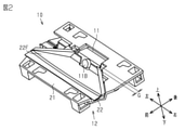
- FIG. 3 is a perspective view showing a state in which the vehicle imager shown in FIG. 1 is assembled.
- FIG. 2 is a plan view of the vehicle imager shown in FIG. 2 as viewed from a viewpoint facing the back surface of the bracket body.
- the end view along the IV-IV line of FIG. The end view along the VV line of FIG.
- the end view along the VI-VI line of FIG. The perspective view which shows the structure of the image pickup machine for a vehicle in 2nd Embodiment by disassembling.
- FIG. 7 is a perspective view showing a state in which the vehicle imager shown in FIG. 7 is assembled.
- FIG. 8 is a plan view of the vehicle imager shown in FIG. 8 as viewed from a viewpoint facing the back surface of the bracket body.
- FIG. 9 is an end view taken along line XX of FIG. The end view along the XI-XI line of FIG. The end view along the XII-XII line of FIG. The end view along the XIII-XIII line of FIG.
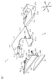
- FIG. 1 A first embodiment of a mounting device for an imager will be described with reference to FIGS. 1 to 6.
- the vehicle imager 10 shown in FIG. 1 is mounted on a surface to be mounted and receives light incident on the surface to be mounted.
- the surface to be mounted is a surface of a transparent member having light transmittance that transmits visible light, and is, for example, a surface on the vehicle interior side of a window glass for a vehicle.
- the vehicle imager 10 is attached to the surface on the vehicle interior side of the pair of surfaces included in the window glass.
- the window glass is, for example, windshield glass, but may be sunroof glass, rear glass, or the like.
- the vehicle imager 10 includes a camera unit 11 and a mounting device 12.
- the camera unit 11 includes a camera body 11A and a lens 11B which is an example of a light receiving unit.
- the camera body 11A includes, for example, an image pickup element, a recording element, and a housing containing these elements.
- the lens 11B is exposed to the outside of the camera body 11A and receives light incident on the mounting surface.
- the mounting device 12 is a device for mounting the camera unit 11 on the mounting target surface.
- the mounting device 12 includes a bracket 21 and a lens hood 22.
- the bracket 21 supports the camera unit 11 having the lens 11B.
- the bracket 21 is mounted on the mounting target surface while supporting the camera unit 11.
- the lens hood 22 has a surface 22F in front of the lens 11B that is widened toward a direction away from the lens 11B.
- the lens hood 22 is attached to the bracket 21 so that the surface 22F faces the attachment target surface.
- the lens hood 22 is removable from the bracket 21 along the mounting target with the camera unit 11 supported by the bracket 21.
- the lens hood 22 can be removed from the bracket 21 supporting the camera unit 11 along the mounting target surface, the camera unit 11 may be removed or the entire mounting device 12 may be removed to remove the lens hood 22. Not accompanied. Therefore, the lens hood 22 can be easily removed.
- the lens hood 22 can be attached to the bracket 21 in the direction opposite to the direction in which the lens hood 22 is removed with the camera unit 11 attached to the bracket 21. Therefore, since the lens hood 22 can be attached to the bracket 21 supporting the camera unit 11 along the attachment target surface, the camera unit 11 can be removed or the entire attachment device 12 can be attached to the lens hood 22. Does not involve removal. Therefore, the lens hood 22 can be easily attached.
- the camera body 11A included in the camera unit 11 has an outer shape in which a substantially L-shaped cross-sectional shape is continuous along the left-right direction of the vehicle imager 10.
- the camera unit 11 includes a first right locking portion 11R1, a second right locking portion 11R2, a first left locking portion 11L1, and a second left locking portion 11L2.
- the pair of right locking portions 11R1 and 11R2 have columns protruding from the right side surface of the camera body 11A in the left-right direction.
- the pair of left locking portions 11L1 and 11L2 have columns protruding from the left side surface of the camera body 11A along the left-right direction.
- the pair of first locking portions 11R1, 11L1 extend along the same central axis.
- the pair of second locking portions 11R2, 11L2 extend along the same central axis at different positions from the pair of first locking portions 11R1, 11L1.
- the pair of second locking portions 11R2 and 11L2 are located in front of the pair of first locking portions 11R1 and 11L1.
- the bracket 21 is attached to the attachment target surface by an attachment member such as an adhesive member or a fastening member.
- the bracket 21 is a resin molded product formed of a synthetic resin.
- the bracket 21 includes a right locking leg 21LR and a left locking leg 21LL.
- the pair of locking legs 21LR and 21LL are arranged at intervals in the left-right direction on the bracket 21.
- Each of the locking legs 21LR and 21LL has a shape extending along the front-rear direction.
- the right locking leg 21LR has a first right locking groove LR1 and a second right locking groove LR2.
- the left locking leg 21LL has a first left locking groove LL1 and a second left locking groove LL2.
- the pair of first locking grooves LR1 and LL1 are located on the same axis extending in the left-right direction.
- the pair of second locking grooves LR2 and LL2 are located on the same axis extending in the left-right direction.
- the pair of second locking grooves LR2 and LL2 are located in front of the pair of first locking grooves LR1 and LL1.
- the first right locking portion 11R1 fits into the first right locking groove LR1 and the first left locking portion 11L1 fits into the first left locking groove LL1. circle. Further, the second right locking portion 11R2 fits into the second right locking groove LR2, and the second left locking portion 11L2 fits into the second left locking groove LL2. As a result, the bracket 21 supports the camera unit 11.
- the bracket 21 has a right locking hole 21HR penetrating the right locking leg 21LR.
- the right locking hole 21HR is located in the middle of the right locking leg 21LR in the front-rear direction.
- the right locking hole 21HR is located above the first right locking groove LR1 and the second right locking groove LR2 of the right locking leg 21LR.
- the bracket 21 is further provided with a left locking piece 21PL and a left guide band 21BL.
- the left locking piece 21PL is located on the rear side of the pair of sides extending in the left-right direction in the bracket 21.
- the left locking piece 21PL and the left guide band 21BL are located above the first left locking groove LL1 and the second locking groove LL2 of the left locking leg 21LL.
- the left guide band 21BL is located below the left locking piece 21PL.
- the left locking piece 21PL has a rectangular shape extending in the front-rear direction, and protrudes into the opening defined by the bracket 21.
- the left guide band 21BL is located on the rear side of the pair of sides extending in the left-right direction in the bracket 21.
- the left guide band 21BL extends in the left-right direction from the left end of the side.
- the bracket 21 has a right bundle branch locking hole (not shown) and a left bundle branch locking hole (see FIG. 4).
- the lens hood 22 is a resin molded product made of synthetic resin, similar to the bracket 21 described above.
- the lens hood 22 includes a hood body 22A.
- the hood body 22A has a substantially trapezoidal shape and has a surface 22F.
- the surface 22F is the surface of the lens hood 22 facing the mounting target surface when the vehicle imager 10 is mounted on the mounting target surface.
- the surface opposite to the front surface 22F is the back surface 22R.
- the lens hood 22 includes a right wall portion 22WR and a left wall portion 22WL.
- the right wall portion 22WR has a substantially L-shape along the right hypotenuse and a part of the upper bottom in the hood main body 22A.
- the left wall portion 22WL has a substantially L-shape along the left hypotenuse and a part of the upper bottom in the hood main body 22A.
- the lens hood 22 includes a right locking projection 22PR, a left locking projection 22PL, a right locking leg 22LR, and a left locking leg 22LL.
- the right locking projection 22PR is projected from the hood body 22A so as to have a shape extending along the direction in which the lens hood 22 is removed.
- the right locking projection 22PR locks the hood body 22A to the bracket 21 through engagement with the bracket 21.
- the right locking projection 22PR is an example of the first locking portion.
- the right locking protrusion 22PR is connected to the rear right end of the hood body 22A.
- the right locking projection 22PR has a rectangular shape extending in the left-right direction.
- the left locking projection 22PL is an example of the second locking portion.
- the left locking projection 22PL is connected to the rear left end of the hood body 22A.
- the left locking projection 22PL has a rectangular shape extending along the front-rear direction, and protrudes from the hood body 22A in the front-rear direction.
- the left locking projection 22PL locks the hood body 22A to the bracket 21 through engagement with the bracket 21.
- the left locking projection 22PL extends along a direction intersecting the extending direction of the right locking projection 22PR.
- the lens hood 22 is inserted into the bracket 21 along the attachment target surface and along the left-right direction in the same manner as when the lens hood 22 is removed.
- the direction in which the lens hood 22 slides at the time of attachment and the direction in which the lens hood 22 slides at the time of removal have opposite directions. That is, the direction in which the lens hood 22 slides at the time of attachment is the direction from the left locking leg 21LL in the bracket 21 toward the right locking leg 21LR.
- the direction in which the lens hood 22 slides at the time of removal is the direction from the right locking leg 21LR in the bracket 21 toward the left locking leg 21LL.
- the lens hood 22 slides in the direction from the right locking leg 21LR to the left locking leg 21LL, so that the left locking projection 22PL is on the right in the direction in which the lens hood 22 is attached. It is located behind the locking projection 22PR.
- the lens hood 22 can be mounted on the bracket 21 by both the right locking protrusion 22PR and the left locking protrusion 22PL. Therefore, the lens hood 22 can be attached to the bracket 21 more stably as compared with the case where the lens hood 22 is attached to the bracket 21 by one locking portion.
- the right locking leg 22LR is connected to the back surface 22R of the hood body 22A.
- the right locking leg 22LR protrudes in the vertical direction from the front side of the hood body 22A.
- the right locking leg 22LR has a substantially L-shaped cross section along a surface defined by the left-right direction and the vertical direction, and the L-shaped cross section has a shape in which the cross section is continuous along the front-rear direction. ..
- the left locking leg 22LL is connected to the back surface 22R of the hood body 22A.
- the left locking leg 22LL protrudes in the vertical direction from the front left end of the hood body 22A.
- the left locking leg 22LL has a substantially L-shaped cross section along a surface defined by the left-right direction and the vertical direction, and the L-shaped cross section has a shape in which the cross section is continuous along the front-rear direction. ..
- the right locking leg 22LR is fitted into the above-mentioned right leg locking hole (see FIG. 4), and the left locking leg 22LL is fitted into the above-mentioned left leg locking hole. ..
- the lens hood 22 is supported by the bracket 21.
- the mounting device 12 includes a heating unit 23.
- the heating unit 23 has a substantially trapezoidal shape. In the left-right direction, the width of the heating unit 23 is substantially equal to the width of the hood body 22A. In the front-rear direction, the width of the heating unit 23 is substantially equal to the width of the hood body 22A.
- the target area to be heated by the heating unit 23 has substantially the same shape and size as the outer shape of the heating unit 23.
- the heating unit 23 may be, for example, a planar heating element.
- the heating unit 23 includes, for example, a good planar conductor, a current-carrying unit, and a pair of insulating films.
- the energizing section is formed by a single heating wire and is connected to a supply section (not shown).
- the energizing portion is sandwiched between a pair of insulating films.
- the good planar conductor is attached on one of the insulating films.
- the supply unit is electrically connected to the heating unit 23 and supplies an electric current to the heating unit 23.
- the heating portion 23 is attached to the back surface 22R of the hood body 22A by an adhesive, an adhesive, or the like.
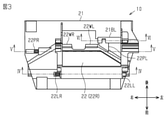
- FIG. 2 shows a state in which the vehicle imager 10 is assembled.
- the camera unit 11 is attached to the pair of locking legs 21LR and 21LL provided in the bracket 21.
- the right locking projection 22PR of the lens hood 22 is inserted into the right locking hole 21HR of the bracket 21, and the left locking projection 22PL is guided to the left of the bracket 21.
- the right locking leg 22LR of the lens hood 22 is fitted into the right leg locking hole (see FIG. 4) of the bracket 21, and the left locking leg 22LL of the lens hood 22 is fitted into the left leg locking hole of the bracket 21. Fit into (see FIG. 4). This makes it possible to attach the lens hood 22 to the bracket 21.
- the distance G between the camera body 11A supporting the lens 11B and the lens hood 22 is such that the lens 11B protrudes from the camera body 11A in the front-rear direction. It is larger than the amount of protrusion. Therefore, when the camera unit 11 is attached to the bracket 21, the camera unit 11 does not interfere with the slide of the lens hood 22. That is, the slide of the lens hood 22 is not hindered by the camera unit 11. Therefore, the lens hood 22 can be attached to the bracket 21 to which the camera unit 11 is attached.
- the camera unit 11 is attached to the bracket 21, and then the bracket 21 that supports the camera unit 11 is attached to the attachment target surface, and then the bracket 21 is attached.
- the lens hood 22 may be attached to the lens hood 22.
- the camera unit 11 and the lens hood 22 may be attached to the bracket 21 in order, and then the bracket 21 may be attached to the attachment target surface. In either case, the lens hood 22 can be attached to the bracket 21 with the camera unit 11 attached to the bracket 21.
- the lens hood 22 can be removed from the bracket 21 while the camera unit 11 is attached to the bracket 21. Since the surface 22F of the lens hood 22 faces the mounting target surface in a state where the vehicle imager 10 is mounted on the mounting target surface, the lens hood 22 is slid along the left-right direction to mount the mounting target surface. It is possible to remove the lens hood 22 along the line. For example, the lens hood 22 removed from the bracket 21 for maintenance or the like can be reattached to the bracket 21 attached to the attachment target surface.
- the locking grooves LR1, LR2, LL1 and LL2 for supporting the camera unit 11 are all the right locking hole 21HR and the left locking piece 21PL for supporting the lens hood 22. , And below the left guide zone 21BL. Therefore, in a state where the camera unit 11 and the lens hood 22 are attached to the bracket 21, the bracket 21 supports a part of the camera unit 11 on the side opposite to the attachment target surface to the lens hood 22. As described above, since the lens hood 22 is removed along the mounting target surface, even if a part of the camera unit 11 is located on the side opposite to the mounting target surface with respect to the lens hood 22, the lens hood 22 can be removed from the bracket 21. Can be removed.
- FIG. 3 shows the planar structure of the vehicle imager 10 as seen from a viewpoint facing the back surface 22R of the lens hood 22.
- FIGS. 3 to 6 referred to below, the left-right direction is reversed from that of FIGS. 1 and 2 for convenience of illustration.
- the camera unit 11 is omitted for convenience of illustration.
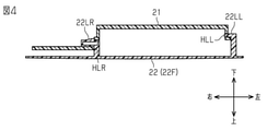
- FIG. 4 shows the end face structure along the IV-IV line shown in FIG.
- FIG. 5 shows an end face structure along the VV line shown in FIG.
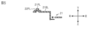
- FIG. 6 shows an end face structure along the VI-VI line shown in FIG.
- each of the right locking projection 22PR, the left locking projection 22PL, the right locking leg 22LR, and the left locking leg 22LL included in the lens hood 22 is a bracket 21. Supported by. As a result, the lens hood 22 is supported by the bracket 21.
- the structure in which the right locking projection 22PR, the left locking projection 22PL, the right locking leg 22LR, and the left locking leg 22LL are each supported by the bracket 21 is constructed. I will explain in more detail.
- FIG. 4 shows a structure in which the right locking leg 22LR and the left locking leg 22LL of the lens hood 22 are supported by the bracket 21.
- the bracket 21 has a right bundle branch locking hole HLR and a left bundle branch locking hole HLL that penetrate the bracket 21 in the left-right direction.
- the right leg locking hole HLR is fitted with the right locking leg 22LR
- the left leg locking hole HLL is fitted with the left locking leg 22LL. ..
- the left leg locking leg 22LL is fitted into the left leg locking hole HLL in a state where it can slide in the left-right direction with respect to the left leg locking hole HLL. Therefore, the left leg locking leg 22LL is removed from the left leg locking hole HLL only by sliding the lens hood 22 in the left-right direction.
- the right locking leg 22LR is restricted from sliding in the left-right direction by the bracket 21.
- the slide restriction by the bracket 21 can be released by pushing up the portion of the right locking leg 22LR that has penetrated the right leg locking hole HLR from the lower side to the upper side.
- the right locking leg 22LR is engaged with the right leg by pushing up the portion of the right locking leg 22LR that has penetrated the right leg locking hole HLR and sliding the lens hood 22 in the left-right direction while maintaining the pushed-up state. It can be removed from the stop hole HLR.
- FIG. 5 shows a structure in which the right locking projection 22PR of the lens hood 22 is supported by the bracket 21.
- the right locking projection 22PR in a state where the lens hood 22 is attached to the bracket 21, the right locking projection 22PR is fitted into the right locking hole 21HR.
- the right locking projection 22PR is restricted from sliding in the left-right direction by the bracket 21.
- the slide restriction by the bracket 21 can be released by pushing up the portion of the right locking projection 22PR that has penetrated the right locking hole 21HR from the lower side to the upper side.
- the right locking projection 22PR is removed from the right locking projection 22PR by sliding the lens hood 22 in the left-right direction while maintaining the state of pushing up the portion of the right locking projection 22PR that has penetrated the right locking hole 21HR. It is possible.
- FIG. 6 shows a structure in which the left locking projection 22PL of the lens hood 22 is supported by the bracket 21.
- the left locking projection 22PL is sandwiched between the left locking piece 21PL and the left guide band 21BL in the vertical direction. Since the left locking protrusion 22PL is sandwiched between the left locking piece 21PL and the left guide band 21BL in a state where it can slide in the left-right direction, the left locking protrusion 22PL can be simply slid in the left-right direction by simply sliding the lens hood 22 in the left-right direction. The 22PL can move to the left of the left locking piece 21PL.
- the lens hood 22 can be removed from the bracket 21 supporting the camera unit 11 along the mounting target surface, the camera unit 11 can be removed to remove the lens hood 22, or the entire mounting device 12 can be removed. Not accompanied by. Therefore, the lens hood 22 can be easily removed.
- the lens hood 22 can be attached to the bracket 21 supporting the camera unit 11 along the attachment target surface, the camera unit 11 can be removed or the entire attachment device 12 can be attached to attach the lens hood 22. Not accompanied by. Therefore, the lens hood 22 can be easily attached.
- the lens hood 22 can be removed from the bracket 21 by sliding the lens hood 22 along the mounting target surface.
- the lens hood 22 can be attached to the bracket 21 by both the right locking protrusion 22PR and the left locking protrusion 22PL. Therefore, the lens hood 22 can be attached to the bracket 21 more stably as compared with the case where the lens hood 22 is attached to the bracket 21 by one locking portion.
- the lens hood 22 Since the lens hood 22 is removed along the mounting target surface, even if a part of the camera unit 11 is located on the side opposite to the mounting target surface with respect to the lens hood 22, the lens hood 22 can be removed from the bracket 21. It can be removed.
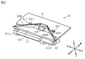
- the vehicle imager 30 shown in FIG. 7 is attached to the mounting target surface and receives light incident through the mounting target surface, similarly to the vehicle imager 10 of the first embodiment.
- the surface to be mounted is a transparent member having light transmittance that transmits visible light, and is, for example, a window glass for a vehicle.
- the vehicle imager 10 is attached to the surface on the vehicle interior side of the pair of surfaces included in the window glass.
- the window glass is, for example, windshield glass, but may be sunroof glass, rear glass, or the like.
- the vehicle imager 30 includes a camera unit 31 and a mounting device 32.
- the camera unit 31 includes a camera body 31A and a lens 31B which is an example of a light receiving unit.
- the camera body 31A includes, for example, an image pickup element, a recording element, and a housing containing these elements.
- the lens 31B is exposed to the outside of the camera body 31A and receives light incident on the mounting surface.
- the mounting device 32 is a device for mounting the camera unit 31 on the mounting target surface.
- the mounting device 32 includes a bracket 41 and a lens hood 42.
- the bracket 41 supports the camera unit 31 having the lens 31B.
- the bracket 41 is mounted on the mounting target surface while supporting the camera unit 31.
- the lens hood 42 has a surface 42F in front of the lens 31B that is widened toward a direction away from the lens 31B.
- the lens hood 42 is attached to the bracket 41 so that the surface 42F faces the attachment target surface.
- the lens hood 42 is removable from the bracket 41 along the mounting target surface in a state where the camera unit 31 is supported by the bracket 41.
- the lens hood 42 can be removed from the bracket 41 supporting the camera unit 31 along the mounting target surface, the removal of the lens hood 42 does not involve the removal of the camera unit 31 or the removal of the entire mounting device 32. .. Therefore, the lens hood 42 can be easily removed.
- the lens hood 42 can be attached to the bracket 41 in the direction opposite to the direction in which the lens hood 42 is removed with the camera unit 31 attached to the bracket 41. Therefore, since the lens hood 42 can be attached to the bracket 41 supporting the camera unit 31 along the attachment target surface, the camera unit 31 may be removed or the entire attachment device 32 may be removed when attaching the lens hood 42. Not accompanied. Therefore, the lens hood 42 can be easily attached.
- the camera body 31A included in the camera unit 31 has an outer shape in which a substantially L-shaped cross-sectional shape is continuous along the left-right direction of the vehicle imager 30.
- the camera unit 31 includes a first right locking portion 31R1, a second right locking portion 31R2, a first left locking portion (not shown), and a second left locking portion (not shown).
- the pair of right locking portions 31R1 and 31R2 have columns protruding from the right side surface of the camera body 31A in the left-right direction.
- the pair of left locking portions have columns protruding from the left side surface of the camera body 31A along the left-right direction.
- the pair of first locking portions extend along the same central axis.
- the pair of second locking portions extends along the same central axis at a position different from that of the pair of first locking portions.
- the pair of second locking portions is located in front of the pair of first locking portions.
- the bracket 41 is attached to the attachment target surface by an attachment member such as an adhesive member or a fastening member.
- the bracket 41 is a resin molded product formed of a synthetic resin.
- the bracket 41 includes a bracket main body 41A having a substantially rectangular plate shape.
- the bracket main body 41A includes a front surface 41F and a back surface 41R opposite to the front surface 41F.
- the surface 41F of the bracket main body 41A is arranged along the mounting target surface when the vehicle imager 30 is mounted on the mounting target surface.
- the bracket body 41A has a substantially V-shaped notch 41C at the front edge extending along the left-right direction.
- the bracket 41 includes a right locking leg 41LR and a left locking leg 41LL.
- the locking legs 41LR and 41LL are connected to the back surface 41R of the bracket main body 41A.
- the 41LL has a shape extending in the front-rear direction, and a part of each of the locking legs 41LR and 41LL is exposed from the notch 41C.
- the right locking leg 41LR has a first right locking groove and a second right locking groove (not shown).
- the left locking leg 21LL has a first left locking groove LL1 and a second left locking groove LL2.
- the pair of first locking grooves are located on the same axis extending along the left-right direction.
- the pair of second locking grooves are located on the same axis extending along the left-right direction.
- the pair of second locking grooves is located in front of the pair of first locking grooves.
- the first right locking portion 31R1 fits into the first right locking groove, and the first left locking portion fits into the first left locking groove LL1. Further, the second right locking portion 31R2 fits into the second right locking groove, and the second left locking portion fits into the second left locking groove LL2. As a result, the bracket 41 supports the camera unit 31.
- the bracket main body 41A includes a first right main body groove AR1 and a first left main body groove AL1.
- the first right main body groove AR1 is located on the right side of the center of the notch 41C.
- the first right main body groove AR1 is recessed on the surface 41F and is open to the notch 41C.
- a hole penetrating the bracket 41 is formed on the side surface of the first right main body groove AR1 along the front-rear direction.
- the first left main body groove AL1 is located on the left side of the center of the notch 41C.
- the first left main body groove AL1 is recessed on the surface 41F and is open to the notch 41C.
- a hole penetrating the bracket 41 is formed on the side surface of the first left main body groove AL1 along the front-rear direction.
- the bracket body 41A includes a second right body groove AR2 and a second left body groove AL2.
- the second main body groove AR2 and the second left main body groove AL2 are located on the side surface of the bracket main body 41A.
- the side surface is a surface connecting the front surface 41F and the back surface 41R.
- the second right main body groove AR2 opens downward at the right end of the notch 41C.
- a hole penetrating the bracket 41 in the front-rear direction is formed on the side surface of the second left main body groove AL2.
- the second left main body groove AL2 opens laterally at the left end of the notch 41C.
- the first right main body groove AR1, the second right main body groove AR2, the first left main body groove AL1, and the second left main body groove AL2 are grooves for fixing the lens hood 42 to the bracket 41.
- the first right main body groove AR1, the second right main body groove AR2, the first left main body groove AL1, and the second left main body groove AL2 are located above the right locking leg 41LR and the left locking leg 41LL. ing.
- the lens hood 42 is a resin molded product made of synthetic resin, similar to the bracket 41 described above.
- the lens hood 42 includes a hood body 42A.
- the hood body 42A has a substantially trapezoidal shape and has a surface 42F.
- the surface 42F is the surface of the lens hood 42 facing the mounting target surface when the vehicle imager 30 is mounted on the mounting target surface.
- the lens hood 42 includes a right wall portion 42WR and a left wall portion 42WL.
- the right wall portion 42WR has a substantially L-shape along the right hypotenuse and a part of the upper bottom in the hood main body 42A.
- the left wall portion 42WL has a substantially L-shape along the left hypotenuse and a part of the upper bottom in the hood main body 42A.
- the lens hood 42 includes a first right locking projection 42R1, a second right locking projection 42R2, a first left locking projection 42L1, and a second left locking projection 42L2.
- Each locking projection 42R1, 42R2, 42L1, 42L2 is an example of a locking portion. That is, each of the locking projections 42R1, 42R2, 42L1, 42L2 locks the hood body 42A to the bracket 41 through engagement with the bracket 41.
- the first right locking projection 42R1 is connected in the middle of the right hypotenuse of the hood body 42A.
- the first right locking projection 42R1 has a rectangular shape extending along the front-rear direction.
- the first left locking projection 42L1 is connected in the middle of the left hypotenuse of the hood body 42A.
- the first left locking projection 42L1 has a rectangular shape extending along the front-rear direction.
- the second right locking projection 42R2 is connected to the right end of the hood body 42A.
- the second right locking projection 42R2 has a substantially rectangular shape extending along the front-rear direction.
- the second left locking projection 42L2 is connected to the left end of the hood body 42A.
- the second left locking projection 42L2 has a substantially rectangular shape extending along the front-rear direction.
- the lens hood 42 attached to the bracket 41 When the lens hood 42 attached to the bracket 41 is removed from the bracket 21, the lens hood 42 is pulled out along the attachment target surface and along the front-rear direction. In this way, since the locking projections 42R1, 42R2, 42L1, 42L2 extend along the direction in which the lens hood 42 is removed, the lens hood 42 is slid from the bracket 41 along the mounting target surface. It can be removed.
- the mounting device 42 includes a heating unit 43.
- the heating unit 43 has a substantially trapezoidal shape. In the left-right direction, the width of the heating unit 43 is substantially equal to the width of the hood body 42A. In the front-rear direction, the width of the heating unit 43 is substantially equal to the width of the hood body 42A.
- the target area to be heated by the heating unit 43 has substantially the same shape and size as the outer shape of the heating unit 43.
- the heating unit 43 may be, for example, a planar heating element.
- the heating unit 43 includes, for example, a good planar conductor, a current-carrying unit, and a pair of insulating films.
- the energizing section is formed by a single heating wire and is connected to a supply section (not shown).
- the energizing portion is sandwiched between a pair of insulating films.
- the good planar conductor is attached on one of the insulating films.
- the supply unit is electrically connected to the heating unit 43 and supplies an electric current to the heating unit 43.
- the heating portion 43 is attached to the back surface of the hood body 42A opposite to the front surface 42F by an adhesive, an adhesive, or the like.
- FIG. 8 shows a state in which the vehicle imager 30 is assembled.
- the camera unit 31 is attached to the pair of locking legs 41LR and 41LL provided in the bracket 41.
- the pair of first locking projections 42R1, 42L1 are inserted into the first main body grooves AR1, AL1 corresponding to the first locking projections 42R1, 42L1.
- the pair of second locking projections 42R2 and 42L2 are inserted into the second main body grooves AR2 and AL2 corresponding to the respective locking projections 42R2 and 42L2. This makes it possible to attach the lens hood 42 to the bracket 41.
- the lens hood 42 is removed from the bracket 41 along the front-rear direction. That is, the lens hood 42 is removed from the bracket 41 by sliding the lens hood 42 toward the front of the lens 31B along the front-rear direction. Therefore, the camera unit 31 does not interfere with the slide of the lens hood 42 when the camera unit 31 is attached to the bracket 41. That is, the slide of the lens hood 42 is not hindered by the camera unit 31. Therefore, the lens hood 42 can be attached to the bracket 41 to which the camera unit 31 is attached.
- the camera unit 31 is attached to the bracket 41 and then the camera unit 31 is supported, as in the vehicle imager 10 of the first embodiment.
- the lens hood 42 may be mounted on the bracket 41.
- the camera unit 31 and the lens hood 42 may be attached to the bracket 41 in order, and then the bracket 41 may be attached to the attachment target surface. In either case, the lens hood 42 can be attached to the bracket 41 with the camera unit 31 attached to the bracket 41.
- the lens hood 42 can be removed from the bracket 41 while the camera unit 31 is attached to the bracket 41. Since the surface 42F of the lens hood 42 faces the mounting target surface in a state where the vehicle imager 30 is mounted on the mounting target surface, the lens hood 42 is slid along the front-rear direction to mount the mounting target surface. It is possible to remove the lens hood 42 along the line. For example, the lens hood 42 removed from the bracket 41 for maintenance or the like can be reattached to the bracket 41 attached to the attachment target surface.
- the pair of locking legs 41LR and 41LL each having the locking groove for supporting the camera unit 31 are the main body grooves AR1, AR2 and AR2 for supporting the lens hood 42. It is located below AL1 and AL2. Therefore, in a state where the camera unit 31 and the lens hood 42 are attached to the bracket 41, the bracket 41 supports a part of the camera unit 31 on the side opposite to the attachment target surface to the lens hood 42. As described above, since the lens hood 42 is removed along the mounting target surface, even if a part of the camera unit 31 is located on the side opposite to the mounting target surface with respect to the lens hood 42, the lens hood 42 can be removed from the bracket 41. Can be removed.
- FIG. 9 shows the planar structure of the vehicle imager 30 as seen from a viewpoint facing the back surface 41R of the bracket 41. Note that, in FIGS. 9 to 13 referred to below, the front-rear direction is reversed from that of FIGS. 7 and 8 for convenience of illustration. Further, in FIGS. 9 to 13, the camera unit 31 is not shown for convenience of illustration.
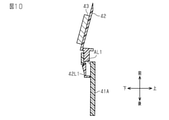
- FIG. 10 shows the end face structure along the XX line shown in FIG.
- FIG. 11 shows an end face structure along the XI-XI line shown in FIG.
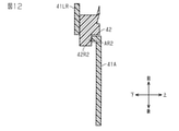
- FIG. 12 shows the end face structure along the XII-XII line shown in FIG.
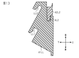
- FIG. 13 shows the end face structure along the line XIII-XIII shown in FIG.
- the locking projections 42R1, 42R2, 42L1, 42L2 included in the lens hood 42 are supported by the bracket 41.
- the lens hood 42 is supported by the bracket 41.
- FIGS. 10 to 13 the structure in which the locking projections 42R1, 42R2, 42L1, 42L2 are supported by the bracket 41 will be described in more detail.
- FIG. 10 shows a structure in which the first left locking projection 42L1 of the lens hood 42 is supported by the bracket 41.
- the first left locking projection 42L1 is fitted into the hole of the first left main body groove AL1.
- the first left locking projection 42L1 is restricted from sliding in the front-rear direction by the bracket 41.
- the slide restriction by the bracket 41 can be released by pushing up the portion of the first left locking projection 42L1 that has penetrated the first left main body groove AL1 from the lower side to the upper side.
- the first left locking projection 42L1 is formed by pushing up the portion of the first left locking projection 42L1 that has penetrated the first left main body groove AL1 and sliding the lens hood 42 in the front-rear direction while maintaining the pushed-up state. Can be removed from the first left body groove AL1.
- FIG. 11 shows a structure in which the first right locking projection 42R1 of the lens hood 42 is supported by the bracket 41.
- the first right locking projection 42R1 is fitted into the hole of the first right main body groove AR1.
- the first right locking projection 42R1 is restricted from sliding in the front-rear direction by the bracket 41.
- the slide restriction by the bracket 41 can be released by pushing up the portion of the first right locking projection 42R1 that has penetrated the first right main body groove AR1 from the lower side to the upper side.
- the first right locking projection 42R1 By pushing up the portion of the first right locking projection 42R1 that penetrates the first right main body groove AR1 and sliding the lens hood 42 in the front-rear direction while maintaining the pushed-up state, the first right locking projection 42R1 Can be removed from the first right body groove AR1.
- FIG. 12 shows a structure in which the second right locking projection 42R2 of the lens hood 42 is supported by the bracket 41.
- the second right locking projection 42R2 is fitted into the bracket main body 41A in a state where it can slide in the front-rear direction with respect to the hole of the second right main body groove AR2. Therefore, the second right locking projection 42R2 is removed from the second right main body groove AR2 only by sliding the lens hood 42 in the front-rear direction.
- FIG. 13 shows a structure in which the second left locking projection 42L2 of the lens hood 42 is supported by the bracket 41.
- the second left locking projection 42L2 can slide in the front-rear direction with respect to the second left main body groove AL2. It is fitted in the groove AL2. Therefore, the second left locking projection 42L2 is removed from the second left main body groove AL2 only by sliding the lens hood 42 in the front-rear direction.
- the heating units 23 and 43 may be located on the surfaces 22F and 42F of the lens hoods 22 and 42.
- the mounting devices 12 and 32 are provided with a reflection suppressing sheet that covers the surfaces of the heating units 23 and 43 and has a lower visible light reflectance than the heating units 23 and 43.
- the lens hoods 22 and 42 are not located between the heating portions 23 and 43 and the mounting target surface, so that the mounting target surface is easily heated.
- brackets 21 and 41 do not have to support a part of the camera units 11 and 31 on the side opposite to the mounting target surface with respect to the lens hoods 22 and 42. That is, the brackets 21 and 41 may support the camera units 11 and 31 only behind the lens hoods 22 and 42. Even in this case, if the vehicle imager 10 of the first embodiment is used, the effects according to the above-mentioned (1) to (4) can be obtained, and the vehicle imager of the second embodiment can be obtained. If it is 30, the effect according to the above-mentioned (1) to (3) can be obtained.
- the lens hood 22 included in the vehicle imager 10 of the first embodiment includes a locking portion extending in the left-right direction, but does not have to include a locking portion extending in a direction intersecting the left-right direction. Even in this case, the effects according to (1) to (3) and (5) described above can be obtained.
- the lens hoods 22 and 42 may be configured so that they can be attached along a direction intersecting the direction in which the lens hoods 22 and 42 are removed from the brackets 21 and 41. Even in this case, if the lens hoods 22 and 42 can be removed from the brackets 21 and 41 along the mounting direction, the effect according to (1) described above can be obtained.
- the lens hoods 22 and 42 may be configured to be removable from the brackets 21 and 41 by rotation about a rotation axis located in the lens hoods 22 and 42. In this case, the lens hoods 22 and 42 may be configured to be movable along the mounting target surface at least immediately after the lens hoods 22 and 42 are removed from the brackets 21 and 41. Alternatively, the lens hoods 22 and 42 may be configured to be removable from the brackets 21 and 41 by rotation about a rotation axis located outside the lens hoods 22 and 42. In this case, the lens hoods 22 and 42 may be configured to be movable along the mounting target surface at least immediately after the lens hoods 22 and 42 are removed from the brackets 21 and 41.
- the lens hoods 22 and 42 are configured to be removable from the brackets 21 and 41 by rotation about a rotation axis located inside the lens hoods 22 and 42, the lens hoods 22 and 42 are at the time of removal. It may be configured so that it can be attached to the brackets 21 and 41 by rotation about the same rotation axis as the rotation axis.
- the lens hoods 22 and 42 are configured to be removable from the brackets 21 and 41 by rotation about a rotation axis located outside the lens hoods 22 and 42, the lens hoods 22 and 42 are at the time of removal. It may be configured so that it can be attached to the brackets 21 and 41 by rotation about the same rotation axis as the rotation axis.
Landscapes
- Engineering & Computer Science (AREA)
- Physics & Mathematics (AREA)
- General Physics & Mathematics (AREA)
- Mechanical Engineering (AREA)
- Multimedia (AREA)
- Signal Processing (AREA)
- Fittings On The Vehicle Exterior For Carrying Loads, And Devices For Holding Or Mounting Articles (AREA)
- Studio Devices (AREA)
- Accessories Of Cameras (AREA)
- Blocking Light For Cameras (AREA)
Abstract
撮像機用取付装置は、受光部を有したカメラユニットを支持し、取付対象面に取り付けられるブラケットと、受光部の前方において、受光部から離れる方向に向けて拡開された表面を有し、表面が取付対象面に対向するようにブラケットに取り付けられるフードと、を備え、フードは、ブラケットにカメラユニットが支持された状態で、取付対象面に沿ってブラケットから取り外し可能である。
Description
本開示は、例えば車両の窓ガラスに搭載される撮像機が備える撮像機用取付装置に関する。
車両用の撮像機は、窓ガラスの一例であるウィンドシールドガラスが有する一対の面のうち、車室内側の面に取り付けられる。撮像機は、自車両の前方に位置する他車両および障害物の有無を検知するために用いられる。
撮像機の第1例は、ウィンドシールドガラスに固定されるブラケット、ブラケットに保持される第1筐体、第1筐体に保持されるカメラユニット、および、第1筐体に取り付けられるフードを備えている。フードは、カメラユニットが備えるレンズの前方において、カメラユニットから離れる方向に向かって広がる略三角形状を有している(例えば、特許文献1を参照)。
撮像機の第2例は、ウィンドシールドガラスに固定される固定ブラケット、カメラユニット、および、カメラユニットを固定ブラケットに取り付けるカメラブラケットを備えている。固定ブラケットには、カメラユニットが固定ブラケットに固定された場合に、カメラユニットが備えるレンズの前方において、カメラユニットから離れる方向に向かって広がる略三角形状を有するフード部分が一体成形されている。すなわち、撮像機の第2例では、撮像機の第1例が備えるフードに相当するフード部分が、固定ブラケットに一体化されている(例えば、特許文献2を参照)。
撮像機の第1例では、第1筐体に取り付けられたフードの端にレンズが組み付けられているため、撮像機からフードを取り外す際に、カメラユニットをフードよりも先に第1筐体から取り外すことが必要である。また、撮像機の第2例では、フードが固定ブラケットに一体化されているから、撮像機をウィンドシールドに取り付けた状態では、撮像機からフードを取り外すことができない。
本開示は、フードを容易に取り外すことを可能とした撮像機用取付装置を提供することを目的とする。
本開示の一態様によれば、撮像機用取付装置は、受光部を有したカメラユニットを支持し、取付対象面に取り付けられるブラケットと、前記受光部の前方において、前記受光部から離れる方向に向けて拡開された表面を有し、前記表面が前記取付対象面に対向するように前記ブラケットに取り付けられるフードと、を備え、前記フードは、前記ブラケットに前記カメラユニットが支持された状態で、前記取付対象面に沿って前記ブラケットから取り外し可能である。
[第1実施形態]
図1から図6を参照して、撮像機用取付装置の第1実施形態を説明する。
図1が示す車両用撮像機10は、取付対象面に取り付けられ、取付対象面を介して入射する光を受光する。取付対象面は、可視光を透過する光透過性を有した透明部材の表面であり、例えば車両用の窓ガラスにおける車室内側の表面である。車両用撮像機10は、窓ガラスが備える一対の面のうち、車室内側の面に取り付けられる。窓ガラスは、例えばウィンドシールドガラスであるが、サンルーフガラス、および、リヤガラスなどであってもよい。車両用撮像機10は、カメラユニット11および取付装置12を備えている。
図1から図6を参照して、撮像機用取付装置の第1実施形態を説明する。
図1が示す車両用撮像機10は、取付対象面に取り付けられ、取付対象面を介して入射する光を受光する。取付対象面は、可視光を透過する光透過性を有した透明部材の表面であり、例えば車両用の窓ガラスにおける車室内側の表面である。車両用撮像機10は、窓ガラスが備える一対の面のうち、車室内側の面に取り付けられる。窓ガラスは、例えばウィンドシールドガラスであるが、サンルーフガラス、および、リヤガラスなどであってもよい。車両用撮像機10は、カメラユニット11および取付装置12を備えている。
カメラユニット11は、カメラ本体11Aと、受光部の一例であるレンズ11Bとを備えている。カメラ本体11Aは、例えば、撮像素子、記録素子、および、これらの素子を内蔵する筐体などを備えている。レンズ11Bは、カメラ本体11Aの外部に露出し、取付対象面を介して入射した光を受光する。
取付装置12は、カメラユニット11を取付対象面に取り付けるための装置である。取付装置12は、ブラケット21、および、レンズフード22を備えている。ブラケット21は、レンズ11Bを有したカメラユニット11を支持する。ブラケット21は、カメラユニット11を支持した状態で、取付対象面に取り付けられる。レンズフード22は、レンズ11Bの前方において、レンズ11Bから離れる方向に向けて拡開された表面22Fを有する。レンズフード22は、表面22Fが取付対象面に対向するようにブラケット21に取り付けられる。レンズフード22は、ブラケット21にカメラユニット11が支持された状態で、取付対象に沿ってブラケット21から取り外し可能である。
カメラユニット11を支持しているブラケット21から取付対象面に沿ってレンズフード22を取り外すことが可能であるから、レンズフード22の取り外しにカメラユニット11の取り外し、または、取付装置12全体の取り外しを伴わない。そのため、レンズフード22を容易に取り外すことが可能である。
また、レンズフード22は、ブラケット21にカメラユニット11が取り付けられた状態で、レンズフード22を取り外す方向とは逆の方向に沿ってブラケット21に取り付け可能である。そのため、カメラユニット11を支持しているブラケット21に取付対象面に沿ってレンズフード22を取り付けることが可能であるから、レンズフード22の取り付けにカメラユニット11の取り外し、または、取付装置12全体の取り外しを伴わない。そのため、レンズフード22を容易に取り付けることが可能である。
以下、車両用撮像機10が備える各部材について、図1を参照してより詳しく説明する。
カメラユニット11が備えるカメラ本体11Aは、略L字状の断面形状が、車両用撮像機10の左右方向に沿って連なった外形を有している。カメラユニット11は、第1右係止部11R1、第2右係止部11R2、第1左係止部11L1、および、第2左係止部11L2を備えている。一対の右係止部11R1,11R2は、カメラ本体11Aの右側面から左右方向に沿って突き出た柱状を有している。一対の左係止部11L1,11L2は、カメラ本体11Aの左側面から左右方向に沿って突き出た柱状を有している。一対の第1係止部11R1,11L1は、同一の中心軸上に沿って延びている。一対の第2係止部11R2,11L2は、一対の第1係止部11R1,11L1とは異なる位置において、同一の中心軸に沿って延びている。一対の第2係止部11R2,11L2は、一対の第1係止部11R1,11L1よりも前方に位置している。
カメラユニット11が備えるカメラ本体11Aは、略L字状の断面形状が、車両用撮像機10の左右方向に沿って連なった外形を有している。カメラユニット11は、第1右係止部11R1、第2右係止部11R2、第1左係止部11L1、および、第2左係止部11L2を備えている。一対の右係止部11R1,11R2は、カメラ本体11Aの右側面から左右方向に沿って突き出た柱状を有している。一対の左係止部11L1,11L2は、カメラ本体11Aの左側面から左右方向に沿って突き出た柱状を有している。一対の第1係止部11R1,11L1は、同一の中心軸上に沿って延びている。一対の第2係止部11R2,11L2は、一対の第1係止部11R1,11L1とは異なる位置において、同一の中心軸に沿って延びている。一対の第2係止部11R2,11L2は、一対の第1係止部11R1,11L1よりも前方に位置している。
ブラケット21は、接着部材や締結部材などの取付部材によって、取付対象面に取り付けられる。ブラケット21は、合成樹脂によって形成された樹脂成形品である。ブラケット21は、右係止脚21LRと左係止脚21LLとを備えている。一対の係止脚21LR,21LLは、ブラケット21において左右方向において間隔を空けて並んでいる。各係止脚21LR,21LLは、前後方向に沿って延びる形状を有している。
右係止脚21LRは、第1右係止溝LR1と、第2右係止溝LR2とを有している。左係止脚21LLは、第1左係止溝LL1と、第2左係止溝LL2とを有している。一対の第1係止溝LR1,LL1は、左右方向に沿って延びる同一の軸上に位置している。一対の第2係止溝LR2,LL2は、左右方向に沿って延びる同一の軸上に位置している。一対の第2係止溝LR2,LL2が、一対の第1係止溝LR1,LL1よりも前方に位置している。
車両用撮像機10が組み立てられる際には、第1右係止部11R1が第1右係止溝LR1に嵌まり、かつ、第1左係止部11L1が第1左係止溝LL1に嵌まる。また、第2右係止部11R2が第2右係止溝LR2に嵌まり、かつ、第2左係止部11L2が第2左係止溝LL2に嵌まる。これにより、ブラケット21がカメラユニット11を支持する。
ブラケット21は、右係止脚21LRを貫通する右係止孔21HRを有している。右係止孔21HRは、右係止脚21LRにおける前後方向の中間に位置している。右係止孔21HRは、右係止脚21LRが有する第1右係止溝LR1および第2右係止溝LR2よりも上方に位置している。
ブラケット21は、さらに左係止片21PL、および、左案内帯21BLを備えている。左係止片21PLは、ブラケット21において左右方向に沿って延びる一対の辺のうち、後方の辺に位置している。左係止片21PLおよび左案内帯21BLは、左係止脚21LLが有する第1左係止溝LL1および第2係止溝LL2よりも上方に位置している。左案内帯21BLは、左係止片21PLの下方に位置している。左係止片21PLは、前後方向に沿って延びる矩形状を有し、ブラケット21が区画する開口内に飛び出ている。左案内帯21BLは、左係止片21PLと同様、ブラケット21において左右方向に沿って延びる一対の辺のうち、後方の辺に位置している。左案内帯21BLは、当該辺の左端から左右方向に沿って延びる。
なお、ブラケット21は、図示されない右脚係止孔、および、左脚係止孔を有している(図4を参照)。
レンズフード22は、上述したブラケット21と同様、合成樹脂によって形成された樹脂成形品である。レンズフード22は、フード本体22Aを備えている。フード本体22Aは略台形状を有し、表面22Fを備えている。表面22Fは、車両用撮像機10が取付対象面に取り付けられた状態において取付対象面と対向するレンズフード22の表面である。フード本体22Aにおいて、表面22Fとは反対側の面が裏面22Rである。
レンズフード22は、上述したブラケット21と同様、合成樹脂によって形成された樹脂成形品である。レンズフード22は、フード本体22Aを備えている。フード本体22Aは略台形状を有し、表面22Fを備えている。表面22Fは、車両用撮像機10が取付対象面に取り付けられた状態において取付対象面と対向するレンズフード22の表面である。フード本体22Aにおいて、表面22Fとは反対側の面が裏面22Rである。
レンズフード22は、右壁部22WRおよび左壁部22WLを備えている。右壁部22WRは、フード本体22Aにおいて、右斜辺と上底の一部とに沿う略L字状を有している。左壁部22WLは、フード本体22Aにおいて、左斜辺と上底の一部とに沿う略L字状を有している。レンズフード22がブラケット21に支持された際には、一対の壁部22WR,22WL間にカメラユニット11のレンズ11Bが位置する。そのため、フード本体22Aは、レンズ11Bの前方においてレンズ11Bから離れる方向に向けて拡開される形状を有している。
レンズフード22は、右係止突起22PR、左係止突起22PL、右係止脚22LR、および、左係止脚22LLを備えている。
右係止突起22PRは、レンズフード22を取り外す方向に沿って延びる形状を有するようにフード本体22Aに突設されている。右係止突起22PRは、ブラケット21との係合を通じてフード本体22Aをブラケット21に係止する。右係止突起22PRは、第1係止部の一例である。
右係止突起22PRは、レンズフード22を取り外す方向に沿って延びる形状を有するようにフード本体22Aに突設されている。右係止突起22PRは、ブラケット21との係合を通じてフード本体22Aをブラケット21に係止する。右係止突起22PRは、第1係止部の一例である。
右係止突起22PRは、フード本体22Aにおける後方の右端に接続されている。右係止突起22PRは、左右方向に沿って延びる矩形状を有している。ブラケット21に取り付けられたレンズフード22がブラケット21から取り外される際には、レンズフード22が、取付対象面に沿い、かつ、左右方向に沿ってブラケット21から引き出される。この際、右係止突起22PRがレンズフード22を取り外す方向に沿って延びるから、取付対象面に沿ってレンズフード22をスライドさせることによって、レンズフード22をブラケット21から取り外すことが可能である。
左係止突起22PLは、第2係止部の一例である。左係止突起22PLは、フード本体22Aにおける後方の左端に接続されている。左係止突起22PLは、前後方向に沿って延びる矩形状を有し、前後方向においてフード本体22Aから突き出ている。左係止突起22PLは、ブラケット21との係合を通じてフード本体22Aをブラケット21に係止する。
左係止突起22PLは、右係止突起22PRの延在方向と交差する方向に沿って延びている。レンズフード22がブラケット21に取り付けられる際には、取り外される際と同様に、レンズフード22が、取付対象面に沿い、かつ、左右方向に沿ってブラケット21に挿入される。ただし、取り付け時にレンズフード22がスライドする方向と、取り外し時にレンズフード22がスライドする方向とは、互いに逆の向きを有する。すなわち、取り付け時にレンズフード22がスライドする方向は、ブラケット21における左係止脚21LLから右係止脚21LRに向かう方向である。これに対して、取り外し時にレンズフード22がスライドする方向は、ブラケット21における右係止脚21LRから左係止脚21LLに向かう方向である。
ブラケット21にレンズフード22を取り付ける際には、レンズフード22が右係止脚21LRから左係止脚21LLに向かう方向にスライドするから、左係止突起22PLは、レンズフード22を取り付ける方向において右係止突起22PRよりも後方に位置する。レンズフード22を取付対象面に沿って取り付けることによって、右係止突起22PRと左係止突起22PLとの両方によってレンズフード22をブラケット21に取り付けることが可能である。そのため、1つの係止部によってレンズフード22をブラケット21に取り付ける場合に比べて、ブラケット21に対してレンズフード22をより安定に取り付けることが可能である。
右係止脚22LRは、フード本体22Aの裏面22Rに接続されている。右係止脚22LRは、フード本体22Aにおける前方の辺から、上下方向に沿って突き出ている。右係止脚22LRは、左右方向と上下方向とによって規定される面に沿う断面において、略L字状を有し、当該L字状の断面が前後方向に沿って連なる形状を有している。
左係止脚22LLは、フード本体22Aの裏面22Rに接続されている。左係止脚22LLは、フード本体22Aにおける前方の左端から、上下方向に沿って突き出ている。左係止脚22LLは、左右方向と上下方向とによって規定される面に沿う断面において、略L字状を有し、当該L字状の断面が前後方向に沿って連なる形状を有している。
車両用撮像機10が組み立てられる際には、右係止脚22LRが上述した右脚係止孔(図4参照)に嵌め込まれ、左係止脚22LLが上述した左脚係止孔に嵌め込まれる。これにより、レンズフード22がブラケット21によって支持される。
取付装置12は、加熱部23を備えている。加熱部23は、略台形状を有している。左右方向において、加熱部23が有する幅は、フード本体22Aが有する幅にほぼ等しい。前後方向において、加熱部23が有する幅は、フード本体22Aが有する幅にほぼ等しい。加熱部23が加熱する対象領域は、加熱部23の外形とほぼ同じ形状および大きさを有する。
加熱部23は、例えば面状発熱体であってよい。加熱部23は、例えば、面状良導体、通電部、および、一対の絶縁フィルムを備えている。通電部は、1本の発熱線によって形成され、図示されない供給部に接続されている。通電部は、一対の絶縁フィルムによって挟まれている。面状良導体は、一方の絶縁フィルム上に貼り付けられている。供給部は、加熱部23に電気的に接続され、加熱部23に電流を供給する。加熱部23は、粘着剤および接着剤などによって、フード本体22Aの裏面22Rに貼り付けられる。
図2は、車両用撮像機10が組み立てられた状態を示している。
図2が示す車両用撮像機10が組み立てられる際には、まず、ブラケット21が備える一対の係止脚21LR,21LLにカメラユニット11を取り付ける。次いで、左右方向に沿ってレンズフード22をスライドさせることによって、レンズフード22の右係止突起22PRをブラケット21の右係止孔21HRに挿入しつつ、左係止突起22PLをブラケット21の左案内帯21BLに沿ってスライドさせる。この際に、レンズフード22の右係止脚22LRをブラケット21の右脚係止孔(図4参照)に嵌め込み、かつ、レンズフード22の左係止脚22LLをブラケット21の左脚係止孔(図4参照)に嵌め込む。これにより、ブラケット21にレンズフード22を取り付けることが可能である。
図2が示す車両用撮像機10が組み立てられる際には、まず、ブラケット21が備える一対の係止脚21LR,21LLにカメラユニット11を取り付ける。次いで、左右方向に沿ってレンズフード22をスライドさせることによって、レンズフード22の右係止突起22PRをブラケット21の右係止孔21HRに挿入しつつ、左係止突起22PLをブラケット21の左案内帯21BLに沿ってスライドさせる。この際に、レンズフード22の右係止脚22LRをブラケット21の右脚係止孔(図4参照)に嵌め込み、かつ、レンズフード22の左係止脚22LLをブラケット21の左脚係止孔(図4参照)に嵌め込む。これにより、ブラケット21にレンズフード22を取り付けることが可能である。
図2が示すように、本実施形態の車両用撮像機10では、前後方向において、レンズ11Bを支持するカメラ本体11Aとレンズフード22との間の間隔Gが、カメラ本体11Aからレンズ11Bが突出する突出量よりも大きい。そのため、カメラユニット11がブラケット21に取り付けられた状態において、カメラユニット11が、レンズフード22のスライドに干渉しない。すなわち、レンズフード22のスライドが、カメラユニット11によって妨げられない。そのため、レンズフード22は、カメラユニット11が取り付けられたブラケット21に対して取り付けられることが可能である。
なお、ブラケット21に対してレンズフード22を初回に取り付ける際には、ブラケット21に対してカメラユニット11を取り付け、次いで、カメラユニット11を支持するブラケット21を取付対象面に取り付けた後に、ブラケット21に対してレンズフード22を取り付けてもよい。あるいは、ブラケット21に対してカメラユニット11とレンズフード22とを順に取り付けた後に、ブラケット21を取付対象面に取り付けてもよい。いずれの場合であっても、ブラケット21にカメラユニット11を取り付けた状態で、ブラケット21に対してレンズフード22を取り付けることが可能である。
一方で、取付対象面に取り付けられたブラケット21からレンズフード22を取り外すことも可能である。上述したように、カメラユニット11はレンズフード22のスライドに干渉しないから、ブラケット21にカメラユニット11が取り付けられた状態において、レンズフード22をブラケット21から取り外すことが可能である。車両用撮像機10が取付対象面に取付られた状態において、レンズフード22の表面22Fが取付対象面に対向しているため、レンズフード22を左右方向に沿ってスライドさせることによって、取付対象面に沿ってレンズフード22を取り外すことが可能である。例えばメンテナンスなどのためにブラケット21から取り外されたレンズフード22は、取付対象面に取り付けられたブラケット21に対して再び取り付けられることが可能である。
上述したように、ブラケット21において、カメラユニット11を支持するための係止溝LR1,LR2,LL1,LL2はいずれも、レンズフード22を支持するための右係止孔21HR、左係止片21PL、および、左案内帯21BLよりも下方に位置している。そのため、ブラケット21に対してカメラユニット11およびレンズフード22が取り付けられた状態において、ブラケット21は、レンズフード22に対する取付対象面とは反対側でカメラユニット11の一部を支持している。上述したようにレンズフード22は取付対象面に沿って取り外されるため、レンズフード22に対して取付対象面とは反対側にカメラユニット11の一部が位置しても、ブラケット21からレンズフード22を取り外すことが可能である。
図3は、レンズフード22の裏面22Rと対向する視点から見た車両用撮像機10の平面構造を示している。なお、以下に参照する図3から図6では、図示の便宜上、図1および図2とは左右方向が逆転している。また、図3から図6では、図示の便宜上、カメラユニット11の図示が省略されている。図4は、図3が示すIV‐IV線に沿う端面構造を示している。図5は、図3が示すV‐V線に沿う端面構造を示している。図6は、図3が示すVI‐VI線に沿う端面構造を示している。
図3が示すように、車両用撮像機10では、レンズフード22が備える右係止突起22PR、左係止突起22PL、右係止脚22LR、および、左係止脚22LLのそれぞれが、ブラケット21によって支持されている。これにより、レンズフード22がブラケット21によって支持されている。以下では、図4から図6を参照して、右係止突起22PR、左係止突起22PL、右係止脚22LR、および、左係止脚22LLのそれぞれがブラケット21によって支持されている構造をより詳しく説明する。
図4は、レンズフード22の右係止脚22LRと左係止脚22LLとがブラケット21によって支持された構造を示している。
図4が示すように、ブラケット21は、左右方向においてブラケット21を貫通する右脚係止孔HLR、および、左脚係止孔HLLを有している。レンズフード22がブラケット21に取り付けられた状態において、右脚係止孔HLRには右係止脚22LRが嵌め込まれ、かつ、左脚係止孔HLLには左係止脚22LLが嵌め込まれている。
図4が示すように、ブラケット21は、左右方向においてブラケット21を貫通する右脚係止孔HLR、および、左脚係止孔HLLを有している。レンズフード22がブラケット21に取り付けられた状態において、右脚係止孔HLRには右係止脚22LRが嵌め込まれ、かつ、左脚係止孔HLLには左係止脚22LLが嵌め込まれている。
左係止脚22LLは、左脚係止孔HLLに対する左右方向でのスライドが可能な状態で左脚係止孔HLLに嵌め込まれている。そのため、左係止脚22LLは、レンズフード22を左右方向にスライドさせるのみによって、左脚係止孔HLLから取り外される。
一方で、右係止脚22LRが右脚係止孔HLRに嵌め込まれた後において、右係止脚22LRは、左右方向でのスライドをブラケット21によって制限されている。ただし、ブラケット21によるスライドの制限は、右係止脚22LRのうちで右脚係止孔HLRを突き抜けた部分を下方から上方に向けて押し上げることによって、解除することが可能である。右係止脚22LRのうちで右脚係止孔HLRを突き抜けた部分を押し上げ、当該押し上げた状態を維持しながらレンズフード22を左右方向にスライドさせることによって、右係止脚22LRを右脚係止孔HLRから取り外すことが可能である。
図5は、レンズフード22の右係止突起22PRがブラケット21によって支持された構造を示している。
図5が示すように、レンズフード22がブラケット21に取り付けられた状態において、右係止突起22PRは、右係止孔21HRに嵌め込まれている。これにより、右係止突起22PRは、左右方向でのスライドをブラケット21によって制限されている。ただし、ブラケット21によるスライドの制限は、右係止突起22PRのうちで右係止孔21HRを突き抜けた部分を下方から上方に向けて押し上げることによって、解除することが可能である。右係止突起22PRのうちで右係止孔21HRを突き抜けた部分を押し上げた状態を維持しながらレンズフード22を左右方向にスライドさせることによって、右係止突起22PRを右係止孔21HRから取り外すことが可能である。
図5が示すように、レンズフード22がブラケット21に取り付けられた状態において、右係止突起22PRは、右係止孔21HRに嵌め込まれている。これにより、右係止突起22PRは、左右方向でのスライドをブラケット21によって制限されている。ただし、ブラケット21によるスライドの制限は、右係止突起22PRのうちで右係止孔21HRを突き抜けた部分を下方から上方に向けて押し上げることによって、解除することが可能である。右係止突起22PRのうちで右係止孔21HRを突き抜けた部分を押し上げた状態を維持しながらレンズフード22を左右方向にスライドさせることによって、右係止突起22PRを右係止孔21HRから取り外すことが可能である。
なお、レンズフード22をブラケット21から取り外すためには、右係止脚22LRに対するスライドの制限と、右係止突起22PRに対するスライドの制限とを同時に解除する必要がある。
図6は、レンズフード22の左係止突起22PLがブラケット21によって支持された構造を示している。
図6が示すように、レンズフード22がブラケット21に取り付けられた状態では、左係止突起22PLは、上下方向において、左係止片21PLと左案内帯21BLとに挟まれている。左係止突起22PLは、左右方向のスライドが可能な状態で左係止片21PLと左案内帯21BLとに挟まれているため、レンズフード22を左右方向にスライドするのみによって、左係止突起22PLは、左係止片21PLよりも左側に移動することが可能である。
図6が示すように、レンズフード22がブラケット21に取り付けられた状態では、左係止突起22PLは、上下方向において、左係止片21PLと左案内帯21BLとに挟まれている。左係止突起22PLは、左右方向のスライドが可能な状態で左係止片21PLと左案内帯21BLとに挟まれているため、レンズフード22を左右方向にスライドするのみによって、左係止突起22PLは、左係止片21PLよりも左側に移動することが可能である。
以上説明したように、撮像機用取付装置の第1実施形態によれば、以下に記載の効果を得ることができる。
(1)カメラユニット11を支持するブラケット21から取付対象面に沿ってレンズフード22を取り外すことが可能であるから、レンズフード22の取り外しにカメラユニット11の取り外し、または、取付装置12全体の取り外しを伴わない。そのため、レンズフード22を容易に取り外すことが可能である。
(1)カメラユニット11を支持するブラケット21から取付対象面に沿ってレンズフード22を取り外すことが可能であるから、レンズフード22の取り外しにカメラユニット11の取り外し、または、取付装置12全体の取り外しを伴わない。そのため、レンズフード22を容易に取り外すことが可能である。
(2)カメラユニット11を支持するブラケット21に取付対象面に沿ってレンズフード22を取り付けることが可能であるから、レンズフード22の取り付けにカメラユニット11の取り外し、または、取付装置12全体の取り外しを伴わない。そのため、レンズフード22を容易に取り付けることが可能である。
(3)右係止突起22PRがレンズフード22を取り外す方向に沿って延びるから、取付対象面に沿ってレンズフード22をスライドさせることによって、レンズフード22をブラケット21から取り外すことが可能である。
(4)右係止突起22PRと左係止突起22PLとの両方によってレンズフード22をブラケット21に取り付けることが可能である。そのため、1つの係止部によってレンズフード22をブラケット21に取り付ける場合に比べて、ブラケット21に対してレンズフード22をより安定に取り付けることが可能である。
(5)レンズフード22は取付対象面に沿って取り外されるため、レンズフード22に対して取付対象面とは反対側にカメラユニット11の一部が位置しても、ブラケット21からレンズフード22を取り外すことが可能である。
[第2実施形態]
図7から図13を参照して、撮像機用取付装置の第2実施形態を説明する。第2実施形態は、上述した第1実施形態と比べて、ブラケットに対してレンズフードをスライドさせる方向が異なっている。そのため以下では、第1実施形態との相違点を特に詳しく説明する。
図7から図13を参照して、撮像機用取付装置の第2実施形態を説明する。第2実施形態は、上述した第1実施形態と比べて、ブラケットに対してレンズフードをスライドさせる方向が異なっている。そのため以下では、第1実施形態との相違点を特に詳しく説明する。
図7が示す車両用撮像機30は、第1実施形態の車両用撮像機10と同様、取付対象面に取り付けられ、取付対象面を介して入射する光を受光する。取付対象面は、可視光を透過する光透過性を有した透明部材であり、例えば車両用の窓ガラスである。車両用撮像機10は、窓ガラスが備える一対の面のうち、車室内側の面に取り付けられる。窓ガラスは、例えばウィンドシールドガラスであるが、サンルーフガラス、および、リヤガラスなどであってもよい。車両用撮像機30は、カメラユニット31および取付装置32を備えている。
カメラユニット31は、カメラ本体31Aと、受光部の一例であるレンズ31Bとを備えている。カメラ本体31Aは、例えば、撮像素子、記録素子、および、これらの素子を内蔵する筐体などを備えている。レンズ31Bは、カメラ本体31Aの外部に露出し、取付対象面を介して入射した光を受光する。
取付装置32は、カメラユニット31を取付対象面に取り付けるための装置である。取付装置32は、ブラケット41、および、レンズフード42を備えている。ブラケット41は、レンズ31Bを有したカメラユニット31を支持する。ブラケット41は、カメラユニット31を支持した状態で、取付対象面に取り付けられる。レンズフード42は、レンズ31Bの前方において、レンズ31Bから離れる方向に向けて拡開された表面42Fを有する。レンズフード42は、表面42Fが取付対象面に対向するようにブラケット41に取り付けられる。レンズフード42は、ブラケット41にカメラユニット31が支持された状態で、取付対象面に沿ってブラケット41から取り外し可能である。
カメラユニット31を支持するブラケット41から取付対象面に沿ってレンズフード42を取り外すことが可能であるから、レンズフード42の取り外しにカメラユニット31の取り外し、または、取付装置32全体の取り外しを伴わない。そのため、レンズフード42を容易に取り外すことが可能である。
また、レンズフード42は、ブラケット41にカメラユニット31が取り付けられた状態で、レンズフード42を取り外す方向とは逆の方向に沿ってブラケット41に取り付け可能である。そのため、カメラユニット31を支持するブラケット41に取付対象面に沿ってレンズフード42を取り付けることが可能であるから、レンズフード42の取り付けにカメラユニット31の取り外し、または、取付装置32全体の取り外しを伴わない。そのため、レンズフード42を容易に取り付けることが可能である。
以下、車両用撮像機30が備える各部材について、図7を参照してより詳しく説明する。
カメラユニット31が備えるカメラ本体31Aは、略L字状の断面形状が、車両用撮像機30の左右方向に沿って連なった外形を有している。カメラユニット31は、第1右係止部31R1、第2右係止部31R2、図示されない第1左係止部、および、図示されない第2左係止部を備えている。一対の右係止部31R1,31R2は、カメラ本体31Aの右側面から左右方向に沿って突き出た柱状を有している。一対の左係止部は、カメラ本体31Aの左側面から左右方向に沿って突き出た柱状を有している。一対の第1係止部は、同一の中心軸上に沿って延びている。一対の第2係止部は、一対の第1係止部とは異なる位置において、同一の中心軸に沿って延びている。一対の第2係止部は、一対の第1係止部よりも前方に位置している。
カメラユニット31が備えるカメラ本体31Aは、略L字状の断面形状が、車両用撮像機30の左右方向に沿って連なった外形を有している。カメラユニット31は、第1右係止部31R1、第2右係止部31R2、図示されない第1左係止部、および、図示されない第2左係止部を備えている。一対の右係止部31R1,31R2は、カメラ本体31Aの右側面から左右方向に沿って突き出た柱状を有している。一対の左係止部は、カメラ本体31Aの左側面から左右方向に沿って突き出た柱状を有している。一対の第1係止部は、同一の中心軸上に沿って延びている。一対の第2係止部は、一対の第1係止部とは異なる位置において、同一の中心軸に沿って延びている。一対の第2係止部は、一対の第1係止部よりも前方に位置している。
ブラケット41は、接着部材や締結部材などの取付部材によって、取付対象面に取り付けられる。ブラケット41は、合成樹脂によって形成された樹脂成形品である。ブラケット41は、略矩形板状を有したブラケット本体41Aを備えている。ブラケット本体41Aは、表面41Fと、表面41Fとは反対側の裏面41Rとを備えている。ブラケット本体41Aの表面41Fは、車両用撮像機30が取付対象面に取り付けられた場合に、取付対象面に沿って配置される。ブラケット本体41Aは、左右方向に沿って延びる前方の縁に、略V字状の切り欠き41Cを有している。
ブラケット41は、右係止脚41LRと左係止脚41LLとを備えている。各係止脚41LR,41LLは、ブラケット本体41Aの裏面41Rに接続されている。各係止脚41LR.41LLは前後方向に沿って延びる形状を有し、各係止脚41LR,41LLの一部が、切り欠き41Cから露出している。
右係止脚41LRは、図示されない第1右係止溝と、第2右係止溝とを有している。左係止脚21LLは、第1左係止溝LL1と、第2左係止溝LL2とを有している。一対の第1係止溝は、左右方向に沿って延びる同一の軸上に位置している。一対の第2係止溝は、左右方向に沿って延びる同一の軸上に位置している。一対の第2係止溝が、一対の第1係止溝よりも前方に位置している。
車両用撮像機30が組み立てられる際には、第1右係止部31R1が第1右係止溝に嵌まり、かつ、第1左係止部が第1左係止溝LL1に嵌まる。また、第2右係止部31R2が第2右係止溝に嵌まり、かつ、第2左係止部が第2左係止溝LL2に嵌まる。これにより、ブラケット41がカメラユニット31を支持する。
ブラケット本体41Aは、第1右本体溝AR1、および、第1左本体溝AL1を備えている。第1右本体溝AR1は、切り欠き41Cの中央よりも右側に位置している。第1右本体溝AR1は、表面41Fにおいて窪み、かつ、切り欠き41Cに開口している。第1右本体溝AR1を区画する側面には、前後方向に沿ってブラケット41を貫通する孔が形成されている。第1左本体溝AL1は、切り欠き41Cの中央よりも左側に位置している。第1左本体溝AL1は、表面41Fにおいて窪み、かつ、切り欠き41Cに開口している。第1左本体溝AL1を区画する側面には、前後方向に沿ってブラケット41を貫通する孔が形成されている。
ブラケット本体41Aは、第2右本体溝AR2、および、第2左本体溝AL2を備えている。第2本体溝AR2および第2左本体溝AL2は、ブラケット本体41Aの側面に位置している。側面は、表面41Fと裏面41Rとを繋ぐ面である。第2右本体溝AR2は、切り欠き41Cの右端において、下方に向けて開口している。第2左本体溝AL2を区画する側面には、前後方向においてブラケット41を貫通する孔が形成されている。第2左本体溝AL2は、切り欠き41Cの左端において、側方に向けて開口している。
第1右本体溝AR1、第2右本体溝AR2、第1左本体溝AL1、および、第2左本体溝AL2は、ブラケット41にレンズフード42を固定するための溝である。第1右本体溝AR1、第2右本体溝AR2、第1左本体溝AL1、および、第2左本体溝AL2は、右係止脚41LR、および、左係止脚41LLよりも上方に位置している。
レンズフード42は、上述したブラケット41と同様、合成樹脂によって形成された樹脂成形品である。レンズフード42は、フード本体42Aを備えている。フード本体42Aは、略台形状を有し、表面42Fを備えている。表面42Fは、車両用撮像機30が取付対象面に取り付けられた応対において取付対象面と対向するレンズフード42の表面である。
レンズフード42は、右壁部42WRおよび左壁部42WLを備えている。右壁部42WRは、フード本体42Aにおいて、右斜辺と上底の一部とに沿う略L字状を有している。左壁部42WLは、フード本体42Aにおいて、左斜辺と上底の一部とに沿う略L字状を有している。レンズフード42がブラケット41に支持された際には、一対の壁部42WR,42WL間にカメラユニット31のレンズ31Bが位置する。そのため、フード本体42Aは、レンズ31Bの前方においてレンズ31Bから離れる方向に向けて拡開される形状を有している。
レンズフード42は、第1右係止突起42R1、第2右係止突起42R2、第1左係止突起42L1、および、第2左係止突起42L2を備えている。各係止突起42R1,42R2,42L1,42L2は、係止部の一例である。すなわち、各係止突起42R1,42R2,42L1,42L2は、ブラケット41との係合を通じてフード本体42Aをブラケット41に係止する。第1右係止突起42R1は、フード本体42Aの右斜辺における途中に接続されている。第1右係止突起42R1は、前後方向に沿って延びる矩形状を有している。第1左係止突起42L1は、フード本体42Aの左斜辺における途中に接続されている。第1左係止突起42L1は、前後方向に沿って延びる矩形状を有している。第2右係止突起42R2は、フード本体42Aの右端に接続されている。第2右係止突起42R2は、前後方向に沿って延びる略矩形状を有している。第2左係止突起42L2は、フード本体42Aの左端に接続されている。第2左係止突起42L2は、前後方向に沿って延びる略矩形状を有している。
ブラケット41に取り付けられたレンズフード42がブラケット21から取り外される際には、レンズフード42が、取付対象面に沿い、かつ、前後方向に沿って引き出される。このように、各係止突起42R1,42R2,42L1,42L2がレンズフード42を取り外す方向に沿って延びるから、取付対象面に沿ってレンズフード42をスライドさせることによって、レンズフード42をブラケット41から取り外すことが可能である。
取付装置42は、加熱部43を備えている。加熱部43は、略台形状を有している。左右方向において、加熱部43が有する幅は、フード本体42Aが有する幅にほぼ等しい。前後方向において、加熱部43が有する幅は、フード本体42Aが有する幅にほぼ等しい。加熱部43が加熱する対象領域は、加熱部43の外形とほぼ同じ形状および大きさを有する。
加熱部43は、例えば面状発熱体であってよい。加熱部43は、例えば、面状良導体、通電部、および、一対の絶縁フィルムを備えている。通電部は、1本の発熱線によって形成され、図示されない供給部に接続されている。通電部は、一対の絶縁フィルムによって挟まれている。面状良導体は、一方の絶縁フィルム上に貼り付けられている。供給部は、加熱部43に電気的に接続され、加熱部43に電流を供給する。加熱部43は、粘着剤および接着剤などによって、フード本体42Aの表面42Fとは反対側の裏面に貼り付けられる。
図8は、車両用撮像機30が組み立てられた状態を示している。
図8が示す車両用撮像機30が組み立てられる際には、まず、ブラケット41が備える一対の係止脚41LR,41LLにカメラユニット31を取り付ける。次いで、前後方向に沿ってレンズフード42をスライドさせることによって、一対の第1係止突起42R1,42L1を各第1係止突起42R1,42L1に対応する第1本体溝AR1,AL1に挿入する。同時に、一対の第2係止突起42R2,42L2を各係止突起42R2,42L2に対応する第2本体溝AR2,AL2に挿入する。これにより、ブラケット41にレンズフード42を取り付けることが可能である。
図8が示す車両用撮像機30が組み立てられる際には、まず、ブラケット41が備える一対の係止脚41LR,41LLにカメラユニット31を取り付ける。次いで、前後方向に沿ってレンズフード42をスライドさせることによって、一対の第1係止突起42R1,42L1を各第1係止突起42R1,42L1に対応する第1本体溝AR1,AL1に挿入する。同時に、一対の第2係止突起42R2,42L2を各係止突起42R2,42L2に対応する第2本体溝AR2,AL2に挿入する。これにより、ブラケット41にレンズフード42を取り付けることが可能である。
本実施形態の車両用撮像機30では、前後方向に沿ってレンズフード42をブラケット41から取り外す。すなわち、前後方向に沿って、レンズ31Bよりも前方に向けてレンズフード42をスライドさせることによってブラケット41からレンズフード42を取り外す。そのため、カメラユニット31がブラケット41に取り付けられた状態において、カメラユニット31が、レンズフード42のスライドに干渉しない。すなわち、レンズフード42のスライドが、カメラユニット31によって妨げられない。そのため、レンズフード42は、カメラユニット31が取り付けられたブラケット41に対して取り付けられることが可能である。
なお、ブラケット41に対してレンズフード42を初回に取り付ける際には、第1実施形態の車両用撮像機10と同様、ブラケット41に対してカメラユニット31を取り付け、次いで、カメラユニット31を支持するブラケット41を取付対象面に取り付けた後に、ブラケット41に対してレンズフード42を取り付けてもよい。あるいは、ブラケット41に対してカメラユニット31とレンズフード42とを順に取り付けた後に、ブラケット41を取付対象面に取り付けてもよい。いずれの場合であっても、ブラケット41にカメラユニット31を取り付けた状態で、ブラケット41に対してレンズフード42を取り付けることが可能である。
一方で、取付対象面に取り付けられたブラケット41からレンズフード42を取り外すことも可能である。上述したように、カメラユニット31はレンズフード42のスライドに干渉しないから、ブラケット41にカメラユニット31が取り付けられた状態において、レンズフード42をブラケット41から取り外すことが可能である。車両用撮像機30が取付対象面に取付られた状態において、レンズフード42の表面42Fが取付対象面に対向しているため、レンズフード42を前後方向に沿ってスライドさせることによって、取付対象面に沿ってレンズフード42を取り外すことが可能である。例えばメンテナンスなどのためにブラケット41から取り外されたレンズフード42は、取付対象面に取り付けられたブラケット41に対して再び取り付けられることが可能である。
上述したように、ブラケット41において、カメラユニット31を支持するための係止溝を有した一対の係止脚41LR,41LLはいずれも、レンズフード42を支持するための各本体溝AR1,AR2,AL1,AL2よりも下方に位置している。そのため、ブラケット41に対してカメラユニット31およびレンズフード42が取り付けられた状態において、ブラケット41は、レンズフード42に対する取付対象面とは反対側にカメラユニット31の一部を支持している。上述したようにレンズフード42は取付対象面に沿って取り外されるため、レンズフード42に対して取付対象面とは反対側にカメラユニット31の一部が位置しても、ブラケット41からレンズフード42を取り外すことが可能である。
図9は、ブラケット41の裏面41Rと対向する視点から見た車両用撮像機30の平面構造を示している。なお、以下参照する図9から図13では、図示の便宜上、図7および図8とは前後方向が逆転している。また、図9から図13では、図示の便宜上、カメラユニット31の図示が省略されている。図10は、図9が示すX‐X線に沿う端面構造を示している。図11は、図9が示すXI‐XI線に沿う端面構造を示している。図12は、図9が示すXII‐XII線に沿う端面構造を示している。図13は、図9が示すXIII‐XIII線に沿う端面構造を示している。
図9が示すように、車両用撮像機30では、レンズフード42が備える係止突起42R1,42R2,42L1,42L2がブラケット41によって支持されている。これにより、レンズフード42がブラケット41によって支持されている。以下では、図10から図13を参照して、各係止突起42R1,42R2,42L1,42L2がブラケット41によって支持されている構造をより詳しく説明する。
図10は、レンズフード42の第1左係止突起42L1がブラケット41によって支持された構造を示している。
図10が示すように、レンズフード42がブラケット41に取り付けられた状態において、第1左係止突起42L1は、第1左本体溝AL1が有する孔に嵌め込まれている。第1左係止突起42L1が第1左本体溝AL1の孔に嵌め込まれた後において、第1左係止突起42L1は、前後方向でのスライドをブラケット41によって制限されている。ただし、ブラケット41によるスライドの制限は、第1左係止突起42L1のうちで第1左本体溝AL1を突き抜けた部分を下方から上方に向けて押し上げることによって、解除することが可能である。第1左係止突起42L1のうちで第1左本体溝AL1を突き抜けた部分を押し上げ、当該押し上げた状態を維持しながらレンズフード42を前後方向にスライドさせることによって、第1左係止突起42L1を第1左本体溝AL1から取り外すことが可能である。
図10が示すように、レンズフード42がブラケット41に取り付けられた状態において、第1左係止突起42L1は、第1左本体溝AL1が有する孔に嵌め込まれている。第1左係止突起42L1が第1左本体溝AL1の孔に嵌め込まれた後において、第1左係止突起42L1は、前後方向でのスライドをブラケット41によって制限されている。ただし、ブラケット41によるスライドの制限は、第1左係止突起42L1のうちで第1左本体溝AL1を突き抜けた部分を下方から上方に向けて押し上げることによって、解除することが可能である。第1左係止突起42L1のうちで第1左本体溝AL1を突き抜けた部分を押し上げ、当該押し上げた状態を維持しながらレンズフード42を前後方向にスライドさせることによって、第1左係止突起42L1を第1左本体溝AL1から取り外すことが可能である。
図11は、レンズフード42の第1右係止突起42R1がブラケット41によって支持された構造を示している。
図11が示すように、レンズフード42がブラケット41に取り付けられた状態において、第1右係止突起42R1は、第1右本体溝AR1が有する孔に嵌め込まれている。第1右係止突起42R1が第1右本体溝AR1の孔に嵌め込まれた後において、第1右係止突起42R1は、前後方向でのスライドをブラケット41によって制限されている。ただし、ブラケット41によるスライドの制限は、第1右係止突起42R1のうちで第1右本体溝AR1を突き抜けた部分を下方から上方に向けて押し上げることによって、解除することが可能である。第1右係止突起42R1のうちで第1右本体溝AR1を突き抜けた部分を押し上げ、当該押し上げた状態を維持しながらレンズフード42を前後方向にスライドさせることによって、第1右係止突起42R1を第1右本体溝AR1から取り外すことができる。
図11が示すように、レンズフード42がブラケット41に取り付けられた状態において、第1右係止突起42R1は、第1右本体溝AR1が有する孔に嵌め込まれている。第1右係止突起42R1が第1右本体溝AR1の孔に嵌め込まれた後において、第1右係止突起42R1は、前後方向でのスライドをブラケット41によって制限されている。ただし、ブラケット41によるスライドの制限は、第1右係止突起42R1のうちで第1右本体溝AR1を突き抜けた部分を下方から上方に向けて押し上げることによって、解除することが可能である。第1右係止突起42R1のうちで第1右本体溝AR1を突き抜けた部分を押し上げ、当該押し上げた状態を維持しながらレンズフード42を前後方向にスライドさせることによって、第1右係止突起42R1を第1右本体溝AR1から取り外すことができる。
なお、レンズフード42をブラケット41から取り外すためには、第1右係止突起42R1に対するスライドの制限と、第1左係止突起42L1に対するスライドの制限との両方を同時に解除する必要がある。
図12は、レンズフード42の第2右係止突起42R2がブラケット41によって支持された構造を示している。
図12が示すように、第2右係止突起42R2は、第2右本体溝AR2の孔に対する前後方向でのスライドが可能な状態でブラケット本体41Aに嵌め込まれている。そのため、第2右係止突起42R2は、レンズフード42を前後方向にスライドさせるのみによって、第2右本体溝AR2から取り外される。
図12が示すように、第2右係止突起42R2は、第2右本体溝AR2の孔に対する前後方向でのスライドが可能な状態でブラケット本体41Aに嵌め込まれている。そのため、第2右係止突起42R2は、レンズフード42を前後方向にスライドさせるのみによって、第2右本体溝AR2から取り外される。
図13は、レンズフード42の第2左係止突起42L2がブラケット41によって支持された構造を示している。
図13が示すように、レンズフード42がブラケット41に取り付けられた状態では、第2左係止突起42L2は、第2左本体溝AL2に対する前後方向でのスライドが可能な状態で第2左本体溝AL2に嵌め込まれている。そのため、第2左係止突起42L2は、レンズフード42を前後方向にスライドさせるのみによって、第2左本体溝AL2から取り外される。
図13が示すように、レンズフード42がブラケット41に取り付けられた状態では、第2左係止突起42L2は、第2左本体溝AL2に対する前後方向でのスライドが可能な状態で第2左本体溝AL2に嵌め込まれている。そのため、第2左係止突起42L2は、レンズフード42を前後方向にスライドさせるのみによって、第2左本体溝AL2から取り外される。
以上説明したように、撮像機用取付装置の第2実施形態によれば、上述した(1)から(3)、および、(5)に準じた効果を得ることができる。
[変更例]
なお、上述した各実施形態は、以下のように変更して実施することができる。
[変更例]
なお、上述した各実施形態は、以下のように変更して実施することができる。
[加熱部]
・加熱部23,43は、レンズフード22,42の表面22F,42Fに位置してもよい。この場合には、取付装置12,32は、加熱部23,43の表面を覆い、かつ、加熱部23,43よりも可視光の反射率が低い反射抑制シートを備えることが好ましい。これにより、加熱部23,43と取付対象面との間にレンズフード22,42が位置しない分だけ、取付対象面が加熱されやすくなる。
・加熱部23,43は、レンズフード22,42の表面22F,42Fに位置してもよい。この場合には、取付装置12,32は、加熱部23,43の表面を覆い、かつ、加熱部23,43よりも可視光の反射率が低い反射抑制シートを備えることが好ましい。これにより、加熱部23,43と取付対象面との間にレンズフード22,42が位置しない分だけ、取付対象面が加熱されやすくなる。
[ブラケット]
・ブラケット21,41は、レンズフード22,42に対する取付対象面とは反対側にカメラユニット11,31の一部を支持しなくともよい。すなわち、ブラケット21,41は、レンズフード22,42よりも後方のみにカメラユニット11,31を支持してもよい。この場合であっても、第1実施形態の車両用撮像機10であれば上述した(1)から(4)に準じた効果を得ることができ、また、第2実施形態の車両用撮像機30であれば上述した(1)から(3)に準じた効果を得ることはできる。
・ブラケット21,41は、レンズフード22,42に対する取付対象面とは反対側にカメラユニット11,31の一部を支持しなくともよい。すなわち、ブラケット21,41は、レンズフード22,42よりも後方のみにカメラユニット11,31を支持してもよい。この場合であっても、第1実施形態の車両用撮像機10であれば上述した(1)から(4)に準じた効果を得ることができ、また、第2実施形態の車両用撮像機30であれば上述した(1)から(3)に準じた効果を得ることはできる。
[レンズフード]
・第1実施形態の車両用撮像機10が備えるレンズフード22は、左右方向に沿って延びる係止部を備える一方で、左右方向と交差する方向に延びる係止部を備えなくてもよい。この場合であっても、上述した(1)から(3)、および、(5)に準じた効果を得ることはできる。
・第1実施形態の車両用撮像機10が備えるレンズフード22は、左右方向に沿って延びる係止部を備える一方で、左右方向と交差する方向に延びる係止部を備えなくてもよい。この場合であっても、上述した(1)から(3)、および、(5)に準じた効果を得ることはできる。
・レンズフード22,42は、ブラケット21,41からレンズフード22,42を取り外す方向と交差する方向に沿った取り付けが可能に構成されてもよい。この場合であっても、ブラケット21,41から取り付け方向に沿ってレンズフード22,42を取り外すことが可能であれば、上述した(1)に準じた効果を得ることはできる。
・レンズフード22,42は、レンズフード22,42内に位置する回転軸を中心とした回転によってブラケット21,41から取り外し可能に構成されてもよい。この場合には、レンズフード22,42は、少なくともブラケット21,41からレンズフード22,42を取り外す直後において取付対象面に沿った移動が可能に構成されていればよい。あるいは、レンズフード22,42は、レンズフード22,42外に位置する回転軸を中心とした回転によってブラケット21,41から取り外し可能に構成されてもよい。この場合には、レンズフード22,42は、少なくともブラケット21,41からレンズフード22,42を取り外す直後において取付対象面に沿った移動が可能に構成されていればよい。
なお、レンズフード22,42がレンズフード22,42内に位置する回転軸を中心とした回転によってブラケット21,41から取り外し可能に構成される場合には、レンズフード22,42は、取り外し時の回転軸と同一の回転軸を中心とする回転によってブラケット21,41に対する取り付けが可能に構成されてもよい。また、レンズフード22,42がレンズフード22,42外に位置する回転軸を中心とした回転によってブラケット21,41から取り外し可能に構成される場合には、レンズフード22,42は、取り外し時の回転軸と同一の回転軸を中心とする回転によってブラケット21,41に対する取り付けが可能に構成されてもよい。
Claims (5)
- 受光部を有したカメラユニットを支持し、取付対象面に取り付けられるブラケットと、
前記受光部の前方において、前記受光部から離れる方向に向けて拡開された表面を有し、前記表面が前記取付対象面に対向するように前記ブラケットに取り付けられるフードと、を備え、
前記フードは、前記ブラケットに前記カメラユニットが支持された状態で、前記取付対象面に沿って前記ブラケットから取り外し可能である
撮像機用取付装置。 - 前記フードは、前記ブラケットに前記カメラユニットが支持された状態で、前記フードを前記ブラケットから取り外す方向とは逆の方向に沿って前記ブラケットに取り付け可能である
請求項1に記載の撮像機用取付装置。 - 前記フードは、
前記受光部の前方において前記受光部から離れる方向に向けて拡開される形状を有したフード本体と、
前記フードを取り外す方向に沿って延びる形状を有するように前記フード本体に突設され、前記ブラケットとの係合を通じて前記フード本体を前記ブラケットに係止する係止部と、を備える
請求項1または2に記載の撮像機用取付装置。 - 前記ブラケットは、前記フードに対する前記取付対象面とは反対側で前記カメラユニットの一部を支持する
請求項1から3のいずれか一項に記載の撮像機用取付装置。 - 前記フードは、
前記受光部の前方において前記受光部から離れる方向に向けて拡開される形状を有したフード本体と、
前記フードを取り付ける方向に沿って延びる形状を有するように前記フード本体に突設され、前記ブラケットとの係合を通じて前記フード本体を前記ブラケットに係止する第1係止部と、
前記第1係止部と交差する方向に沿って延び、前記フードを取り付ける方向において前記第1係止部よりも後方に位置し、前記ブラケットとの係合を通じて前記フード本体を前記ブラケットに係止する第2係止部を備える
請求項2に記載の撮像機用取付装置。
Priority Applications (3)
| Application Number | Priority Date | Filing Date | Title |
|---|---|---|---|
| US18/016,967 US12194929B2 (en) | 2020-07-22 | 2021-06-30 | Imaging device for mounting device |
| EP21846299.2A EP4186752A4 (en) | 2020-07-22 | 2021-06-30 | IMAGING DEVICE MOUNTING DEVICE |
| CN202180048492.XA CN115835981B (zh) | 2020-07-22 | 2021-06-30 | 摄像机用安装装置 |
Applications Claiming Priority (2)
| Application Number | Priority Date | Filing Date | Title |
|---|---|---|---|
| JP2020125494A JP7344853B2 (ja) | 2020-07-22 | 2020-07-22 | 撮像機用取付装置 |
| JP2020-125494 | 2020-07-22 |
Publications (1)
| Publication Number | Publication Date |
|---|---|
| WO2022019066A1 true WO2022019066A1 (ja) | 2022-01-27 |
Family
ID=79729419
Family Applications (1)
| Application Number | Title | Priority Date | Filing Date |
|---|---|---|---|
| PCT/JP2021/024684 Ceased WO2022019066A1 (ja) | 2020-07-22 | 2021-06-30 | 撮像機用取付装置 |
Country Status (5)
| Country | Link |
|---|---|
| US (1) | US12194929B2 (ja) |
| EP (1) | EP4186752A4 (ja) |
| JP (1) | JP7344853B2 (ja) |
| CN (1) | CN115835981B (ja) |
| WO (1) | WO2022019066A1 (ja) |
Families Citing this family (1)
| Publication number | Priority date | Publication date | Assignee | Title |
|---|---|---|---|---|
| JP7802296B2 (ja) * | 2023-02-01 | 2026-01-20 | 株式会社ニフコ | 車載機器取付構造 |
Citations (10)
| Publication number | Priority date | Publication date | Assignee | Title |
|---|---|---|---|---|
| US20150251605A1 (en) * | 2014-03-10 | 2015-09-10 | Magna Mirrors Of America, Inc. | Vehicle vision system with camera and mirror mount |
| DE102014224860A1 (de) * | 2014-12-04 | 2016-06-09 | Conti Temic Microelectronic Gmbh | Streulichtblende |
| WO2016125965A1 (ko) * | 2015-02-04 | 2016-08-11 | 엘지전자 주식회사 | 스테레오 카메라 |
| JP2018012406A (ja) | 2016-07-20 | 2018-01-25 | 株式会社ニフコ | カメラユニット |
| US20180069993A1 (en) * | 2015-03-12 | 2018-03-08 | Trw Automotive U.S. Llc | Low gloss housing assembly for a driver assist system camera |
| JP2019064425A (ja) | 2017-09-29 | 2019-04-25 | 株式会社デンソー | 車載カメラ装置 |
| JP2019137289A (ja) * | 2018-02-13 | 2019-08-22 | 株式会社Subaru | 車外監視装置 |
| WO2019245661A1 (en) * | 2018-06-20 | 2019-12-26 | Trw Automotive U.S. Llc | Driver assist system |
| JP2020097331A (ja) * | 2018-12-18 | 2020-06-25 | 本田技研工業株式会社 | 輸送機器およびセンサブラケット |
| JP2020131809A (ja) * | 2019-02-14 | 2020-08-31 | トヨタ自動車株式会社 | カメラ搭載構造 |
Family Cites Families (6)
| Publication number | Priority date | Publication date | Assignee | Title |
|---|---|---|---|---|
| WO2013019795A1 (en) | 2011-08-02 | 2013-02-07 | Magna Electronics Inc. | Vehicular camera system |
| WO2013123161A1 (en) * | 2012-02-17 | 2013-08-22 | Magna Electronics, Inc. | Vehicle vision system with light baffling system |
| JP5761100B2 (ja) * | 2012-03-28 | 2015-08-12 | 株式会社デンソー | 車載カメラ |
| KR101698783B1 (ko) | 2013-12-16 | 2017-01-23 | 엘지전자 주식회사 | 스테레오 카메라 및 이를 구비한 차량 |
| CN106476714A (zh) * | 2015-08-27 | 2017-03-08 | 日本电产艾莱希斯株式会社 | 车载摄像头以及车载摄像头的制造方法 |
| JP6726265B2 (ja) * | 2018-12-18 | 2020-07-22 | 本田技研工業株式会社 | センサブラケット |
-
2020
- 2020-07-22 JP JP2020125494A patent/JP7344853B2/ja active Active
-
2021
- 2021-06-30 WO PCT/JP2021/024684 patent/WO2022019066A1/ja not_active Ceased
- 2021-06-30 CN CN202180048492.XA patent/CN115835981B/zh active Active
- 2021-06-30 EP EP21846299.2A patent/EP4186752A4/en active Pending
- 2021-06-30 US US18/016,967 patent/US12194929B2/en active Active
Patent Citations (10)
| Publication number | Priority date | Publication date | Assignee | Title |
|---|---|---|---|---|
| US20150251605A1 (en) * | 2014-03-10 | 2015-09-10 | Magna Mirrors Of America, Inc. | Vehicle vision system with camera and mirror mount |
| DE102014224860A1 (de) * | 2014-12-04 | 2016-06-09 | Conti Temic Microelectronic Gmbh | Streulichtblende |
| WO2016125965A1 (ko) * | 2015-02-04 | 2016-08-11 | 엘지전자 주식회사 | 스테레오 카메라 |
| US20180069993A1 (en) * | 2015-03-12 | 2018-03-08 | Trw Automotive U.S. Llc | Low gloss housing assembly for a driver assist system camera |
| JP2018012406A (ja) | 2016-07-20 | 2018-01-25 | 株式会社ニフコ | カメラユニット |
| JP2019064425A (ja) | 2017-09-29 | 2019-04-25 | 株式会社デンソー | 車載カメラ装置 |
| JP2019137289A (ja) * | 2018-02-13 | 2019-08-22 | 株式会社Subaru | 車外監視装置 |
| WO2019245661A1 (en) * | 2018-06-20 | 2019-12-26 | Trw Automotive U.S. Llc | Driver assist system |
| JP2020097331A (ja) * | 2018-12-18 | 2020-06-25 | 本田技研工業株式会社 | 輸送機器およびセンサブラケット |
| JP2020131809A (ja) * | 2019-02-14 | 2020-08-31 | トヨタ自動車株式会社 | カメラ搭載構造 |
Non-Patent Citations (1)
| Title |
|---|
| See also references of EP4186752A4 |
Also Published As
| Publication number | Publication date |
|---|---|
| CN115835981B (zh) | 2025-11-28 |
| EP4186752A4 (en) | 2024-07-24 |
| US12194929B2 (en) | 2025-01-14 |
| US20230280636A1 (en) | 2023-09-07 |
| EP4186752A1 (en) | 2023-05-31 |
| CN115835981A (zh) | 2023-03-21 |
| JP2022021723A (ja) | 2022-02-03 |
| JP7344853B2 (ja) | 2023-09-14 |
Similar Documents
| Publication | Publication Date | Title |
|---|---|---|
| CN104736392B (zh) | 显示镜组件 | |
| US10112540B2 (en) | Full display rearview device | |
| EP2868511B1 (en) | Display apparatus for vehicle | |
| JP6553186B2 (ja) | ディスプレイミラーアセンブリ | |
| CN103163647B (zh) | 平视显示装置 | |
| CN112424674B (zh) | 机动车的显示装置、产生对光学图像信息的虚拟显示的方法以及机动车 | |
| CN104169780B (zh) | 车辆用显示装置 | |
| CN120245866A (zh) | 显示镜组件 | |
| KR20180039702A (ko) | 백미러 어셈블리용 토글 메커니즘 | |
| WO2022019066A1 (ja) | 撮像機用取付装置 | |
| WO2018079308A1 (ja) | ヘッドアップディスプレイ装置 | |
| JP6650118B2 (ja) | 乗員監視装置 | |
| KR20070098628A (ko) | 후면 투사형 디스플레이 장치 | |
| JP7369677B2 (ja) | 撮像機用加熱装置 | |
| US11601614B2 (en) | Display unit with cable accomodation groove | |
| JP6969424B2 (ja) | 平面鏡ユニット | |
| WO2018079307A1 (ja) | ヘッドアップディスプレイ装置 | |
| JP4607433B2 (ja) | 液晶ディスプレイ装置 | |
| JP2018151632A (ja) | ヘッドアップディスプレイ装置 | |
| US20250271669A1 (en) | Head-up display | |
| JP7484637B2 (ja) | ヘッドアップディスプレイ装置 | |
| CN220154724U (zh) | 背光装置、抬头显示器及车辆 | |
| KR101493441B1 (ko) | 차량용 블랙박스 | |
| JP2024075830A (ja) | ヘッドアップディスプレイ装置 | |
| JP5994436B2 (ja) | 車両用表示装置 |
Legal Events
| Date | Code | Title | Description |
|---|---|---|---|
| 121 | Ep: the epo has been informed by wipo that ep was designated in this application |
Ref document number: 21846299 Country of ref document: EP Kind code of ref document: A1 |
|
| NENP | Non-entry into the national phase |
Ref country code: DE |
|
| ENP | Entry into the national phase |
Ref document number: 2021846299 Country of ref document: EP Effective date: 20230222 |