WO2022019127A1 - チラー - Google Patents
チラー Download PDFInfo
- Publication number
- WO2022019127A1 WO2022019127A1 PCT/JP2021/025708 JP2021025708W WO2022019127A1 WO 2022019127 A1 WO2022019127 A1 WO 2022019127A1 JP 2021025708 W JP2021025708 W JP 2021025708W WO 2022019127 A1 WO2022019127 A1 WO 2022019127A1
- Authority
- WO
- WIPO (PCT)
- Prior art keywords
- cooling water
- temperature
- tank
- chiller
- pipe
- Prior art date
- Legal status (The legal status is an assumption and is not a legal conclusion. Google has not performed a legal analysis and makes no representation as to the accuracy of the status listed.)
- Ceased
Links
Images
Classifications
-
- F—MECHANICAL ENGINEERING; LIGHTING; HEATING; WEAPONS; BLASTING
- F25—REFRIGERATION OR COOLING; COMBINED HEATING AND REFRIGERATION SYSTEMS; HEAT PUMP SYSTEMS; MANUFACTURE OR STORAGE OF ICE; LIQUEFACTION SOLIDIFICATION OF GASES
- F25B—REFRIGERATION MACHINES, PLANTS OR SYSTEMS; COMBINED HEATING AND REFRIGERATION SYSTEMS; HEAT PUMP SYSTEMS
- F25B6/00—Compression machines, plants or systems, with several condenser circuits
- F25B6/02—Compression machines, plants or systems, with several condenser circuits arranged in parallel
-
- F—MECHANICAL ENGINEERING; LIGHTING; HEATING; WEAPONS; BLASTING
- F25—REFRIGERATION OR COOLING; COMBINED HEATING AND REFRIGERATION SYSTEMS; HEAT PUMP SYSTEMS; MANUFACTURE OR STORAGE OF ICE; LIQUEFACTION SOLIDIFICATION OF GASES
- F25B—REFRIGERATION MACHINES, PLANTS OR SYSTEMS; COMBINED HEATING AND REFRIGERATION SYSTEMS; HEAT PUMP SYSTEMS
- F25B5/00—Compression machines, plants or systems, with several evaporator circuits, e.g. for varying refrigerating capacity
- F25B5/02—Compression machines, plants or systems, with several evaporator circuits, e.g. for varying refrigerating capacity arranged in parallel
-
- F—MECHANICAL ENGINEERING; LIGHTING; HEATING; WEAPONS; BLASTING
- F25—REFRIGERATION OR COOLING; COMBINED HEATING AND REFRIGERATION SYSTEMS; HEAT PUMP SYSTEMS; MANUFACTURE OR STORAGE OF ICE; LIQUEFACTION SOLIDIFICATION OF GASES
- F25B—REFRIGERATION MACHINES, PLANTS OR SYSTEMS; COMBINED HEATING AND REFRIGERATION SYSTEMS; HEAT PUMP SYSTEMS
- F25B25/00—Machines, plants or systems, using a combination of modes of operation covered by two or more of the groups F25B1/00 - F25B23/00
- F25B25/005—Machines, plants or systems, using a combination of modes of operation covered by two or more of the groups F25B1/00 - F25B23/00 using primary and secondary systems
-
- F—MECHANICAL ENGINEERING; LIGHTING; HEATING; WEAPONS; BLASTING
- F25—REFRIGERATION OR COOLING; COMBINED HEATING AND REFRIGERATION SYSTEMS; HEAT PUMP SYSTEMS; MANUFACTURE OR STORAGE OF ICE; LIQUEFACTION SOLIDIFICATION OF GASES
- F25B—REFRIGERATION MACHINES, PLANTS OR SYSTEMS; COMBINED HEATING AND REFRIGERATION SYSTEMS; HEAT PUMP SYSTEMS
- F25B41/00—Fluid-circulation arrangements
- F25B41/20—Disposition of valves, e.g. of on-off valves or flow control valves
-
- F—MECHANICAL ENGINEERING; LIGHTING; HEATING; WEAPONS; BLASTING
- F25—REFRIGERATION OR COOLING; COMBINED HEATING AND REFRIGERATION SYSTEMS; HEAT PUMP SYSTEMS; MANUFACTURE OR STORAGE OF ICE; LIQUEFACTION SOLIDIFICATION OF GASES
- F25D—REFRIGERATORS; COLD ROOMS; ICE-BOXES; COOLING OR FREEZING APPARATUS NOT OTHERWISE PROVIDED FOR
- F25D17/00—Arrangements for circulating cooling fluids; Arrangements for circulating gas, e.g. air, within refrigerated spaces
- F25D17/02—Arrangements for circulating cooling fluids; Arrangements for circulating gas, e.g. air, within refrigerated spaces for circulating liquids, e.g. brine
-
- F—MECHANICAL ENGINEERING; LIGHTING; HEATING; WEAPONS; BLASTING
- F25—REFRIGERATION OR COOLING; COMBINED HEATING AND REFRIGERATION SYSTEMS; HEAT PUMP SYSTEMS; MANUFACTURE OR STORAGE OF ICE; LIQUEFACTION SOLIDIFICATION OF GASES
- F25B—REFRIGERATION MACHINES, PLANTS OR SYSTEMS; COMBINED HEATING AND REFRIGERATION SYSTEMS; HEAT PUMP SYSTEMS
- F25B2339/00—Details of evaporators; Details of condensers
- F25B2339/04—Details of condensers
- F25B2339/047—Water-cooled condensers
-
- F—MECHANICAL ENGINEERING; LIGHTING; HEATING; WEAPONS; BLASTING
- F25—REFRIGERATION OR COOLING; COMBINED HEATING AND REFRIGERATION SYSTEMS; HEAT PUMP SYSTEMS; MANUFACTURE OR STORAGE OF ICE; LIQUEFACTION SOLIDIFICATION OF GASES
- F25B—REFRIGERATION MACHINES, PLANTS OR SYSTEMS; COMBINED HEATING AND REFRIGERATION SYSTEMS; HEAT PUMP SYSTEMS
- F25B2400/00—Component parts or details not otherwise provided for in this subclass
- F25B2400/04—Refrigeration circuit bypassing means
- F25B2400/0403—Refrigeration circuit bypassing means for condensers
-
- F—MECHANICAL ENGINEERING; LIGHTING; HEATING; WEAPONS; BLASTING
- F25—REFRIGERATION OR COOLING; COMBINED HEATING AND REFRIGERATION SYSTEMS; HEAT PUMP SYSTEMS; MANUFACTURE OR STORAGE OF ICE; LIQUEFACTION SOLIDIFICATION OF GASES
- F25B—REFRIGERATION MACHINES, PLANTS OR SYSTEMS; COMBINED HEATING AND REFRIGERATION SYSTEMS; HEAT PUMP SYSTEMS
- F25B2600/00—Control issues
- F25B2600/02—Compressor control
- F25B2600/025—Compressor control by controlling speed
- F25B2600/0253—Compressor control by controlling speed with variable speed
-
- F—MECHANICAL ENGINEERING; LIGHTING; HEATING; WEAPONS; BLASTING
- F25—REFRIGERATION OR COOLING; COMBINED HEATING AND REFRIGERATION SYSTEMS; HEAT PUMP SYSTEMS; MANUFACTURE OR STORAGE OF ICE; LIQUEFACTION SOLIDIFICATION OF GASES
- F25B—REFRIGERATION MACHINES, PLANTS OR SYSTEMS; COMBINED HEATING AND REFRIGERATION SYSTEMS; HEAT PUMP SYSTEMS
- F25B2600/00—Control issues
- F25B2600/11—Fan speed control
- F25B2600/111—Fan speed control of condenser fans
-
- F—MECHANICAL ENGINEERING; LIGHTING; HEATING; WEAPONS; BLASTING
- F25—REFRIGERATION OR COOLING; COMBINED HEATING AND REFRIGERATION SYSTEMS; HEAT PUMP SYSTEMS; MANUFACTURE OR STORAGE OF ICE; LIQUEFACTION SOLIDIFICATION OF GASES
- F25B—REFRIGERATION MACHINES, PLANTS OR SYSTEMS; COMBINED HEATING AND REFRIGERATION SYSTEMS; HEAT PUMP SYSTEMS
- F25B2600/00—Control issues
- F25B2600/25—Control of valves
- F25B2600/2501—Bypass valves
-
- F—MECHANICAL ENGINEERING; LIGHTING; HEATING; WEAPONS; BLASTING
- F25—REFRIGERATION OR COOLING; COMBINED HEATING AND REFRIGERATION SYSTEMS; HEAT PUMP SYSTEMS; MANUFACTURE OR STORAGE OF ICE; LIQUEFACTION SOLIDIFICATION OF GASES
- F25B—REFRIGERATION MACHINES, PLANTS OR SYSTEMS; COMBINED HEATING AND REFRIGERATION SYSTEMS; HEAT PUMP SYSTEMS
- F25B2700/00—Sensing or detecting of parameters; Sensors therefor
- F25B2700/19—Pressures
- F25B2700/193—Pressures of the compressor
- F25B2700/1933—Suction pressures
-
- F—MECHANICAL ENGINEERING; LIGHTING; HEATING; WEAPONS; BLASTING
- F25—REFRIGERATION OR COOLING; COMBINED HEATING AND REFRIGERATION SYSTEMS; HEAT PUMP SYSTEMS; MANUFACTURE OR STORAGE OF ICE; LIQUEFACTION SOLIDIFICATION OF GASES
- F25B—REFRIGERATION MACHINES, PLANTS OR SYSTEMS; COMBINED HEATING AND REFRIGERATION SYSTEMS; HEAT PUMP SYSTEMS
- F25B2700/00—Sensing or detecting of parameters; Sensors therefor
- F25B2700/21—Temperatures
- F25B2700/2115—Temperatures of a compressor or the drive means therefor
- F25B2700/21151—Temperatures of a compressor or the drive means therefor at the suction side of the compressor
-
- F—MECHANICAL ENGINEERING; LIGHTING; HEATING; WEAPONS; BLASTING
- F25—REFRIGERATION OR COOLING; COMBINED HEATING AND REFRIGERATION SYSTEMS; HEAT PUMP SYSTEMS; MANUFACTURE OR STORAGE OF ICE; LIQUEFACTION SOLIDIFICATION OF GASES
- F25B—REFRIGERATION MACHINES, PLANTS OR SYSTEMS; COMBINED HEATING AND REFRIGERATION SYSTEMS; HEAT PUMP SYSTEMS
- F25B2700/00—Sensing or detecting of parameters; Sensors therefor
- F25B2700/21—Temperatures
- F25B2700/2115—Temperatures of a compressor or the drive means therefor
- F25B2700/21152—Temperatures of a compressor or the drive means therefor at the discharge side of the compressor
-
- F—MECHANICAL ENGINEERING; LIGHTING; HEATING; WEAPONS; BLASTING
- F25—REFRIGERATION OR COOLING; COMBINED HEATING AND REFRIGERATION SYSTEMS; HEAT PUMP SYSTEMS; MANUFACTURE OR STORAGE OF ICE; LIQUEFACTION SOLIDIFICATION OF GASES
- F25B—REFRIGERATION MACHINES, PLANTS OR SYSTEMS; COMBINED HEATING AND REFRIGERATION SYSTEMS; HEAT PUMP SYSTEMS
- F25B2700/00—Sensing or detecting of parameters; Sensors therefor
- F25B2700/21—Temperatures
- F25B2700/2116—Temperatures of a condenser
- F25B2700/21163—Temperatures of a condenser of the refrigerant at the outlet of the condenser
-
- F—MECHANICAL ENGINEERING; LIGHTING; HEATING; WEAPONS; BLASTING
- F25—REFRIGERATION OR COOLING; COMBINED HEATING AND REFRIGERATION SYSTEMS; HEAT PUMP SYSTEMS; MANUFACTURE OR STORAGE OF ICE; LIQUEFACTION SOLIDIFICATION OF GASES
- F25B—REFRIGERATION MACHINES, PLANTS OR SYSTEMS; COMBINED HEATING AND REFRIGERATION SYSTEMS; HEAT PUMP SYSTEMS
- F25B41/00—Fluid-circulation arrangements
- F25B41/30—Expansion means; Dispositions thereof
- F25B41/385—Dispositions with two or more expansion means arranged in parallel on a refrigerant line leading to the same evaporator
-
- F—MECHANICAL ENGINEERING; LIGHTING; HEATING; WEAPONS; BLASTING
- F25—REFRIGERATION OR COOLING; COMBINED HEATING AND REFRIGERATION SYSTEMS; HEAT PUMP SYSTEMS; MANUFACTURE OR STORAGE OF ICE; LIQUEFACTION SOLIDIFICATION OF GASES
- F25B—REFRIGERATION MACHINES, PLANTS OR SYSTEMS; COMBINED HEATING AND REFRIGERATION SYSTEMS; HEAT PUMP SYSTEMS
- F25B49/00—Arrangement or mounting of control or safety devices
- F25B49/02—Arrangement or mounting of control or safety devices for compression type machines, plants or systems
-
- H—ELECTRICITY
- H01—ELECTRIC ELEMENTS
- H01S—DEVICES USING THE PROCESS OF LIGHT AMPLIFICATION BY STIMULATED EMISSION OF RADIATION [LASER] TO AMPLIFY OR GENERATE LIGHT; DEVICES USING STIMULATED EMISSION OF ELECTROMAGNETIC RADIATION IN WAVE RANGES OTHER THAN OPTICAL
- H01S3/00—Lasers, i.e. devices using stimulated emission of electromagnetic radiation in the infrared, visible or ultraviolet wave range
- H01S3/02—Constructional details
- H01S3/04—Arrangements for thermal management
- H01S3/0407—Liquid cooling, e.g. by water
-
- H—ELECTRICITY
- H01—ELECTRIC ELEMENTS
- H01S—DEVICES USING THE PROCESS OF LIGHT AMPLIFICATION BY STIMULATED EMISSION OF RADIATION [LASER] TO AMPLIFY OR GENERATE LIGHT; DEVICES USING STIMULATED EMISSION OF ELECTROMAGNETIC RADIATION IN WAVE RANGES OTHER THAN OPTICAL
- H01S3/00—Lasers, i.e. devices using stimulated emission of electromagnetic radiation in the infrared, visible or ultraviolet wave range
- H01S3/23—Arrangements of two or more lasers not provided for in groups H01S3/02 - H01S3/22, e.g. tandem arrangements of separate active media
- H01S3/2383—Parallel arrangements
Definitions
- the present invention relates to a chiller for controlling the temperature of a heat load by supplying temperature-controlled cooling water to the heat load.
- Patent Document 1 describes a chiller that controls the temperature of a plurality of heat loads by supplying temperature-controlled cooling water to a plurality of heat loads and exchanging heat.
- the chiller described in Patent Document 1 includes a plurality of coolant circuits for supplying cooling water to each of a plurality of devices, one refrigerating circuit for controlling the temperature of the cooling water, and a control device for controlling the entire chiller. Have. Two heat exchangers are connected in parallel to the refrigeration circuit, and each of these heat exchangers is connected to each of the plurality of coolant circuits. Therefore, the cooling water that has cooled the equipment is temperature-controlled by the heat exchanger of the refrigerating circuit and supplied to the equipment again.
- the cooling water supplied to the equipment is used as a tank by branching from the supply pipe for supplying the cooling water heat-exchanged by the heat exchanger of the coolant circuit to the equipment.
- An ion removal filter (DI filter) for removing an ionic substance in the cooling water is provided in the filtration line connected to the return line.
- DI filter ion removal filter
- ionic substances in the cooling water can be removed to generate pure water with higher purity.
- a filtration pipe and a DI filter are provided in only one of the two coolant circuits. Therefore, when the other coolant circuit also requires higher purity pure water, the other coolant circuit is also provided with a filtration line, a DI filter, a solenoid valve for opening and closing the filtration line, and the like. It is conceivable to provide it. However, when the filtration line, the DI filter and the solenoid valve are added in this way, the size of the entire chiller becomes large and the cost and energy consumption cannot be avoided. On the other hand, as a result of space saving, energy saving, and cost saving, a chiller that is smaller in size and can suppress an increase in energy and cost is desired by a user.
- the technical subject of the present invention is to provide a DI filter capable of removing ionic substances contained in cooling water that controls the temperature of each of a plurality of heat loads, and to provide a chiller that is small in size and can suppress an increase in energy and cost. To do.
- the chiller of the present invention is a chiller that controls the temperature of a plurality of heat loads by circulating cooling water, and is a plurality of cooling water circuits that separately supply the cooling water to the plurality of heat loads. And a refrigerating circuit through which a primary refrigerant that controls the temperature of the cooling water flows, and the refrigerating circuit is configured by connecting the same number of heat exchange flow paths as the cooling water circuit in parallel with each other.
- Each of these heat exchange flow paths is provided with a heat exchanger, and each of the plurality of cooling water circuits is the heat exchanger of the corresponding heat exchange flow path among the plurality of heat exchange flow paths.
- Each of the plurality of cooling water circuits is connected to a tank in which the cooling water is housed and a heat exchange flow path portion corresponding to the cooling water in the tank.
- a first supply line for supplying to the heat exchanger, a pump provided in the first supply line, and a second for delivering the cooling water whose temperature is controlled by the heat exchanger to the heat load. It has a supply pipeline and a return pipeline that guides the cooling water returned from the heat load to the tank, and further, the chiller is the second supply of any one of the plurality of cooling water circuits.
- It has a filtration conduit that branches from the conduit and is connected to the return conduit of the other cooling water circuit, and the filtration conduit is provided with a DI filter for purifying the cooling water. ..
- a communication pipeline for keeping the amount of the cooling water stored in the respective tanks constant is connected between the tanks provided in each of the plurality of cooling water circuits. There is. Further, the flow rate of the cooling water flowing from the filtration pipe through the return pipe to the tank flows out of the tank and flows out from the tank through the communication pipe to the second supply pipe. It is preferable that the flow rate of the cooling water flowing into the tank provided in the cooling water circuit to which the path is connected is the same as the flow rate of the cooling water.
- the solenoid valve has a control device for controlling the entire chiller, and allows or blocks the inflow of the cooling water from the second supply line to the filter line in the filter line.
- the return pipe is provided with a conductivity sensor for measuring the electric conductivity of the cooling water flowing in the return pipe, and the control device is provided with an electric conduction measured by the conductivity sensor. The opening and closing of the solenoid valve is controlled according to the rate.
- the chiller of the present invention is provided with a DI filter capable of removing ionic substances contained in cooling water that controls the temperature of each of a plurality of heat loads, and provides a chiller that is small in size and can suppress an increase in energy and cost. Can be done.
- the cooling water is fresh water
- the heat load will be described by exemplifying a laser oscillator in a laser welding apparatus and a probe that irradiates a laser beam.
- the laser oscillator has a low temperature load
- the probe has a higher temperature load than the laser oscillator.
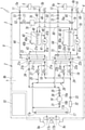
- the chiller 1 shown in FIG. 1 controls the temperatures of the two first devices 5 (heat load) and the second device 6 (heat load), and the two first cooling water circuits 3 (cooling water circuits) and the two first cooling water circuits 3 (cooling water circuits). It has a second cooling water circuit 4 (cooling water circuit), one refrigerating circuit 2, and a control device 10 for controlling the entire chiller 1.
- the first cooling water circuit 3 supplies the first cooling water 7 to the first device 5, the second cooling water circuit 4 supplies the second cooling water 8 to the second device 6, and the first device 5 and the second cooling water circuit 4 supply the second cooling water 8.
- the device 6 is cooled separately.
- the refrigerating circuit 2 has a primary refrigerant for controlling the temperature of the first cooling water 7 of the first cooling water circuit 3 and the second cooling water 8 of the second cooling water circuit 4, respectively, and is a primary refrigerant. Controls the temperatures of the first cooling water 7 and the second cooling water 8 by exchanging heat with the first cooling water 7 and the second cooling water 8, respectively, so that the first cooling water 7 and the second cooling water 8 can be separated from each other. It controls the temperature to the set temperature.
- the primary refrigerant for example, hydrofluorocarbon (HFC) or a natural refrigerant (ammonia, carbon dioxide, etc.) can be used.
- the first device 5 is a laser oscillator in a laser welding device and is a low temperature device
- the other second device 6 is a probe that irradiates a laser beam and is a high temperature device. ..
- the first cooling water circuit 3 cools the first device 5 with the first cooling water 7
- the second cooling water circuit 4 cools the second device 6 with the second cooling water 8.
- fresh water is used as the first cooling water 7 supplied to the first device 5.
- the temperature of the fresh water is set to the optimum temperature in the range of 10-30 ° C, preferably 15-25 ° C.
- the flow rate of fresh water is set to the optimum flow rate in the range of 20-80 L / min.
- pure water is used as the second cooling water 8 supplied to the second device 6, and the temperature of the pure water is in the range of 10-50 ° C, preferably in the range of 20-40 ° C to the optimum temperature.
- the flow rate of pure water is set to the optimum flow rate in the range of 2-10 L / min.
- the set temperature of the second cooling water 8 needs to be equal to the set temperature of the first cooling water 7 or higher than the set temperature of the first cooling water 7.
- the refrigerating circuit 2, the two first cooling water circuits 3 and the second cooling water circuit 4 are housed inside one housing 9, and the two first equipment 5 and the second equipment 6 are housed 9. It is arranged outside.
- two device connection ports 11 and 12 for connecting the first device 5 to the first cooling water circuit 3 and a second device 6 for connecting to the second cooling water circuit 4 are provided.
- the two device connection ports 13 and 14 are provided, respectively.
- the refrigeration circuit 2 includes a compressor 16 that compresses the primary refrigerant into a high-temperature and high-pressure gas, and a condenser 17 that cools the high-temperature and high-pressure gaseous primary refrigerant discharged from the compressor 16 into a low-temperature and high-pressure liquid.
- the first main expansion valve 18 and the second main expansion valve 19 and the first main expansion valve 18 and the second main expansion valve 19 that expand the low-temperature and high-pressure primary refrigerant sent from the condenser 17 to make the low-temperature and low-pressure liquid liquid.
- Low-temperature low-pressure liquid primary refrigerant sent from is exchanged separately between the first cooling water 7 and the second cooling water 8 of the two first cooling water circuits 3 and the second cooling water circuit 4, and is a low-pressure gas.
- the first heat exchanger 21 and the second heat exchanger 22 that are used as the primary refrigerant are connected in series and in a loop in order by pipes.
- the first main expansion valve 18 and the first heat exchanger 21 are connected in series with each other to form the first heat exchange flow path portion 23, and the second main expansion valve 19 and the second heat exchanger 22 are also mutually connected. Is connected in series to form a second heat exchange flow path portion 24.
- the first heat exchange flow path portion 23 and the second heat exchange flow path portion 24 are in the middle of the flow path from the outlet of the condenser 17 to the suction ports 21a and 22a of the first heat exchanger 21 and the second heat exchanger 22. Branched in parallel with each other so as to join each other in the flow path between the outlets 21b and 22b of the first heat exchanger 21 and the second heat exchanger 22 and the suction port 16a of the compressor 16. ing.
- a primary refrigerant flow section 21d through which the primary refrigerant flows and a cooling water flow section 21e through which the first cooling water 7 flows are provided and flow inside the primary refrigerant flow section 21d. Heat exchange is performed between the primary refrigerant and the first cooling water 7 flowing in the cooling water flow unit 21e.
- a primary refrigerant flow section 22d through which the primary refrigerant flows and a cooling water flow section 22e through which the second cooling water 8 flows are provided inside the case 22c, and the primary refrigerant flows. Heat exchange is performed between the primary refrigerant flowing in the section 22d and the second cooling water 8 flowing in the cooling water flow section 22e.
- the flow rate of the primary refrigerant flowing through the primary refrigerant flow section 21d of the first heat exchanger 21 and the primary refrigerant flow section 22d of the second heat exchanger 22 is the opening degree of the first main expansion valve 18 and the second main expansion valve 19. By increasing or decreasing, the amount is increased or decreased, and the cooling capacity of the first heat exchanger 21 and the second heat exchanger 22 is controlled accordingly.
- the first main expansion valve 18 and the second main expansion valve 19 are expansion valves for cooling, and supply a low-temperature primary refrigerant to the first heat exchanger 21 and the second heat exchanger 22.
- the flow path connecting the discharge port 16b of the compressor 16 and the inlet 17a of the condenser 17 is branched from this flow path to the first heat exchanger 21 of the first heat exchange flow path portion 23.
- the first branch flow path 25 connected between the first main expansion valve 18 and the second heat exchanger 22 and the second main expansion valve 19 of the second heat exchange flow path portion 24 branched from the flow path.
- a first sub-expansion valve 27 is connected to the first branch flow path 25, and a second sub-expansion valve 28 is connected to the second branch flow path 26.
- first branch flow path 25 and the second branch flow path 26 a part of the high-temperature primary refrigerant discharged from the compressor 16 is used as a heating refrigerant in the first heat exchange flow path portion 23 and the second heat exchange flow path. It is supplied to the unit 24. By supplying the heating refrigerant, the temperature of the cooling water flowing in the first heat exchanger 21 and the second heat exchanger 22 is controlled.
- the flow rate of the heating refrigerant increases or decreases by increasing or decreasing the opening degree of the first sub-expansion valve 27 and the second sub-expansion valve 28, and accordingly, the cooling flowing to the first heat exchanger 21 and the second heat exchanger 22.
- the temperature of the water is controlled. Therefore, the first sub-expansion valve 27 and the second sub-expansion valve 28 are expansion valves for heating.
- the first main expansion valve 18, the second main expansion valve 19, the first sub-expansion valve 27, and the second sub-expansion valve 28 are electronic expansion valves whose opening degree can be arbitrarily controlled by a stepping motor. There is, and it is electrically connected to the control device 10, and each opening degree is controlled by the control device 10.
- the condenser 17 is an air-cooled condenser that cools the primary refrigerant by a fan 17c driven by an electric motor 17b.
- the fan 17c is arranged in a fan accommodating portion 9a formed on the side surface of the housing 9, and the fan accommodating portion 9a is provided with an intake port 9c for sucking outside air toward the condenser 17 as cooling air.
- the cooling air sucked from the intake port 9c cools the primary refrigerant when passing through the condenser 17, and then is discharged to the outside of the housing 9 from the exhaust port 9b opened at the upper part of the housing 9.
- the condenser 17 is not limited to the air-cooled type, but may be a water-cooled type.
- a control device 10 for controlling the operation of the entire chiller 1 is provided in the housing 9.
- the compressor 16 and the fan 17c are electrically connected to the control device 10, and their respective rotation speeds, outputs, and the like are controlled by inverter control by the control device 10.
- a first temperature sensor 31 is provided in the flow path from the discharge port 16b of the compressor 16 to the inlet 17a of the condenser 17 in order to measure the temperature of the primary refrigerant discharged from the compressor 16. Be connected. Further, the filter 32 for filtering impurities in the primary refrigerant and the pressure of the primary refrigerant are measured in the flow paths from the outlet 17d of the condenser 17 to the first heat exchange flow path portion 23 and the second heat exchange flow path portion 24. The first pressure sensor 33 is sequentially connected.
- a second temperature sensor 34 for measuring the temperature of the primary refrigerant flowing out of the first heat exchanger 21 is connected to the first heat exchange flow path portion 23 and the flow path leading to the suction port 16a of the compressor 16.
- a second pressure sensor 35 for measuring the pressure of the primary refrigerant sucked into the compressor 16 and a third temperature sensor 36 for measuring the temperature of the primary refrigerant are located downstream of the second temperature sensor 34 on the downstream side of the flow path. It is connected.
- the first temperature sensor 31, the second temperature sensor 34, the third temperature sensor 36, the first pressure sensor 33, and the second pressure sensor 35 are electrically connected to the control device 10, and are based on the measurement results thereof.
- the control device 10 controls the rotation speed, output, and the like of the electric motor 17b of the compressor 16 and the condenser 17.
- the portion from the discharge port 16b of the compressor 16 to the first main expansion valve 18 and the second main expansion valve 19 via the condenser 17 is a high-pressure side portion where the pressure of the primary refrigerant is high.
- the portion from the outlets of the first main expansion valve 18 and the second main expansion valve 19 to the suction port 16a of the compressor 16 via the first heat exchanger 21 and the second heat exchanger 22 is This is the low pressure side where the pressure of the primary refrigerant is low.
- the first cooling water circuit 3 includes a first tank 40 accommodating the first cooling water 7, a first pump 41 installed outside the first tank 40, a discharge port 41a of the first pump 41, and a first heat.
- a first supply line 43 connecting the inlet of the cooling water flow section 21e of the exchanger 21 and a second supply line 44 connecting the outlet of the cooling water flow section 21e and the equipment connection port 11 on the supply side.
- a return pipe 45 that connects the equipment connection port 12 on the return side and the first tank 40, and a return communication pipe that guides the first cooling water 7 flowing out of the first tank 40 to the suction port 41b of the first pump 41. 46 and.
- the equipment pipe 5a on the supply side and the equipment pipe 5b on the return side of the first device 5 are connected to the device connection port 11 on the supply side and the device connection port 12 on the return side.
- the first cooling water circuit 3 sends the first cooling water 7 in the first tank 40 to the cooling water flow section 21e of the first heat exchanger 21 by the first pump 41, and the cooling water flow section 21e thereof.
- the first cooling water 7 is heat-exchanged with the primary refrigerant flowing in the primary refrigerant flow unit 21d to control the set temperature, and then immediately sent to the first device 5 through the second supply pipeline 44. There is.
- the first tank 40 is formed in a box shape with a hollow inside.
- An injection port 40a into which the first cooling water 7 can be injected is provided in the upper part of the first tank 40, and a lid portion 40b is detachably provided in the injection port 40a.
- a level switch 48 for detecting the liquid level of the first cooling water 7 is provided in the first tank 40.
- a drain pipe 50 communicating with a drain port 49 provided on the outer surface of the housing 9 is connected to the first tank 40.
- a supply side temperature sensor 51 for measuring the temperature of the first cooling water 7 heading for the first device 5 under temperature control by the first heat exchanger 21 and a first cooling water 7 are provided. It is connected to the supply side pressure sensor 52 that measures the pressure of the above.
- the supply-side temperature sensor 51 and the supply-side pressure sensor 52 are electrically connected to the control device 10, and based on the measured temperature and pressure of the first cooling water 7, the control device 10 causes the first pump 41 and the like.
- Each expansion valve 18, 19, 27, 28, etc. of the refrigeration circuit 2 is controlled.
- the second cooling water circuit 4 includes a second tank 60 accommodating the second cooling water 8, a second pump 61 installed outside the second tank 60, a discharge port 61a of the second pump 61, and a second heat.
- a first supply line 63 connecting the inlet of the cooling water flow section 22e of the exchanger 22 and a second supply line 64 connecting the outlet of the cooling water flow section 22e and the equipment connection port 13 on the supply side.
- It has a return pipeline 65 that connects the device connection port 14 on the return side and the second tank 60.
- the equipment pipe 6a on the supply side and the equipment pipe 6b on the return side of the second device 6 are connected to the device connection port 13 on the supply side and the device connection port 14 on the return side.
- the second cooling water circuit 4 sends the second cooling water 8 in the second tank 60 to the cooling water flow section 22e of the second heat exchanger 22 by the second pump 61, and the cooling water flow section 22e serves as the second cooling water circuit 4. It is configured to exchange heat with the primary refrigerant flowing in the primary refrigerant flow unit 22d to control the set temperature, and then immediately send the heat to the second device 6 through the second supply pipeline 64.
- the second tank 60 is formed in a box shape with a hollow inside.
- An injection port 60a into which the second cooling water 8 can be injected is provided in the upper part of the second tank 60, and a lid portion 60b is detachably attached to the injection port 60a.
- the lid portion 60b is attached to the injection port 60a, the internal space inside the second tank 60 is shielded from the outside air.
- the second tank 60 is provided with a level switch 68 for detecting the liquid level of the second cooling water 8 stored in the second tank 60, and is provided on the outer surface of the housing 9 and communicates with the drain port 69.
- the drain pipe 70 is connected.
- a temperature sensor 73 for measuring the temperature of the second cooling water 8 supplied from the second pump 61 to the second heat exchanger 22 is connected to the first supply pipe line 63.
- a supply-side temperature sensor 71 that measures the temperature of the second cooling water 8 that is temperature-controlled by the second heat exchanger 22 and heads toward the second device 6 and the pressure of the second cooling water 8 Is connected to the supply side pressure sensor 72 for measuring.
- the supply-side temperature sensor 71, the temperature sensor 73, and the supply-side pressure sensor 72 are electrically connected to the control device 10, and based on the measured temperature, pressure, and the like of the second cooling water 8, the control device 10 makes a second.
- the expansion valves 18, 19, 27, 28 and the like of the 2 pump 61 and the refrigeration circuit 2 are controlled.
- first cooling water circuit 3 and the second cooling water circuit 4 are branched from the second supply line 44 of the first cooling water circuit 3 and connected to the return line 65 of the second cooling water circuit 4.
- a filtration line 76 is provided.
- the connection position of the filtration line 76 with respect to the second supply line 44 is on the upstream side of the supply side pressure sensor 52 provided in the second supply line 44.
- a solenoid valve 77 for opening and closing the filtration pipe line 76 and a DI filter 78 (Deionized Filter) for purifying the first cooling water 7 are connected to the filtration pipe line 76.
- the solenoid valve 77 is a two-way solenoid valve, and the second supply line 44 and the return line 65 are switched to communicate or shut off by opening and closing.
- the DI filter 78 includes an ion exchange resin filter through which the first cooling water 7 can pass.
- the ion exchange resin filter has a function of adsorbing and removing ionic substances in the first cooling water 7 when the first cooling water 7 flows. Therefore, when the first cooling water 7 of fresh water is passed through the DI filter 78, the fresh water can be turned into pure water.
- a conductivity sensor 79 for measuring the electric conductivity in the pure water-purified first cooling water 7 is provided.
- the solenoid valve 77 and the conductivity sensor 79 are electrically connected to the control device 10, and the solenoid valve 77 is controlled by the control device 10 based on the measured electrical conductivity.
- the filtration pipe line 76 is a pipe line for removing the ionic substance in the first cooling water 7 (fresh water) to turn the fresh water into pure water, and the solenoid valve 77 is usually closed. As a result, the filtration pipe line 76 is blocked.
- the conductivity sensor 79 detects that the amount of the ionic substance in the second cooling water 8 has increased and the electric conductivity of the second cooling water 8 has increased
- the solenoid valve 77 is opened and the piping is filtered.
- the pipeline 76 returns the first cooling water 7 of the first supply pipeline 43 to the second tank 60 through the DI filter 78 and the filtration pipeline 76 and the return pipeline 65. At that time, the ionic substance in the first cooling water 7 is removed by the DI filter 78, and the first cooling water 7 becomes pure water.
- the DI filter 78 is arranged inside the housing 9, but the DI filter 78 may be arranged outside the housing 9. In this case, the DI filter 78 can be easily replaced by providing the DI filter 78 in a detachable manner with respect to the filtration pipe line 76.
- the first cooling stored in the first tank 40 and the second tank 60 is provided between the first tank 40 and the second tank 60 provided in the first cooling water circuit 3 and the second cooling water circuit 4, the first cooling stored in the first tank 40 and the second tank 60 is provided.
- a communication pipeline 80 for keeping the liquid level (amount) of the water 7 and the second cooling water 8 constant is connected.
- the communication line 80 is connected to a position where one end of the communication line 80 is below the liquid level of the first cooling water 7 stored in the first tank 40, and the other end of the communication line 80 is connected. Is connected to a position below the liquid level of the second cooling water 8 stored in the second tank 60.
- the first tank 40 and the second tank 60 communicate with each other through the communication pipe line 80, and when the first cooling water 7 purified from the filtration pipe line 76 flows into the second tank 60, the second tank The liquid level of 60 rises, and the second cooling water 8 (pure water) stored in the second tank 60 flows into the first tank 40 via the communication pipe 80.
- the first tank 40 and the second tank 60 communicate with the outside air and are installed at the same height. Therefore, when the first cooling water 7 flows into the second tank 60 through the filtration pipe line 76 and the liquid level in the second tank 60 rises, the second cooling water 8 corresponding to the rise in the liquid level becomes. It flows into the first tank 40 through the communication pipeline 80. That is, the amount of cooling water that has flowed into the second tank 60 returns to the first tank 40. Therefore, the liquid level (amount) of each of the first tank 40 and the second tank 60 can be kept constant.
- the electric conductivity of the second cooling water 8 stored in the second tank 60 can be reduced. ..
- the electric conductivity of the first cooling water 7 stored in the first tank 40 communicating with the second tank 60 can also be reduced.
- the high-temperature and high-pressure primary refrigerant discharged from the compressor 16 is cooled by the condenser 17 to a low-temperature and high-pressure state, and then the first heat exchange flow path portion 23 and the second heat exchange flow path portion. It flows to each of 24.
- the primary refrigerant that has flowed into the first heat exchange flow path portion 23 is brought into a low temperature and low pressure state by the first main expansion valve 18, and then in the first heat exchanger 21, the first cooling water of the first cooling water circuit 3 By cooling 7, the temperature rises and evaporates to a low pressure state.
- the primary refrigerant flowing into the second heat exchange flow path portion 24 is brought into a low temperature and low pressure state by the second main expansion valve 19, and then in the second heat exchanger 22, the second cooling water circuit 4 second.
- the temperature rises and evaporates to a low pressure state.
- the primary refrigerants from the first heat exchanger 21 and the second heat exchanger 22 merge and flow into the suction port 16a of the compressor 16.
- a part of the high temperature and high pressure primary refrigerant discharged from the compressor 16 passes through the first branch flow path 25 and the second branch flow path 26 to the first heat exchange flow path portion 23 and the second heat exchange flow path portion. It is supplied to 24 as a heating refrigerant.
- this heating refrigerant By supplying this heating refrigerant, the temperatures of the first cooling water 7 and the second cooling water 8 toward the first heat exchanger 21 and the second heat exchanger 22 are controlled, and as a result, the first heat exchanger 21 and The cooling capacity of the second heat exchanger 22 is controlled.
- the first cooling water 7 in the first tank 40 is sent from the first pump 41 to the cooling water flow unit 21e of the first heat exchanger 21 through the first supply pipeline 43. Then, after being controlled to a set temperature by heat exchange with the primary refrigerant of the refrigerating circuit 2 by the first heat exchanger 21, it is sent from the second supply pipeline 44 to the first equipment 5 through the equipment connection port 11 on the supply side. The first device 5 is cooled. The first cooling water 7 whose temperature has been raised by cooling the first device 5 is returned to the first tank 40 from the device connection port 12 on the return side through the return pipe 45.
- the temperature of the first cooling water 7 is constantly measured by the supply-side temperature sensor 51, and based on the measured temperature of the first cooling water 7, the first main expansion valve 18 and the first sub-expansion valve 27 of the refrigeration circuit 2 By controlling the opening degree, the temperature of the first cooling water 7 is finely controlled and maintained at the set temperature.
- the opening degree of the first main expansion valve 18 in the refrigeration circuit 2 is expanded to increase the flow rate of the low-temperature primary refrigerant flowing through the first heat exchange flow path portion 23, and the opening degree of the first sub-expansion valve 27 is increased.
- the temperature of the primary refrigerant flowing into the first heat exchanger 21 decreases and the cooling capacity of the first heat exchanger 21 increases, so that the first cooling water 7 is cooled and its temperature decreases and is set. Controlled by temperature.
- the first main expansion valve 18 is used.
- the opening degree of the first sub-expansion valve 27 is increased to reduce the flow rate of the low-temperature primary refrigerant flowing through the first heat exchange flow path portion 23, and the opening degree of the first sub-expansion valve 27 is increased to the first branch flow path 25 to the first.
- the flow rate of the high-temperature heating refrigerant flowing into the heat exchange flow path portion 23 is increased.
- the temperature of the primary refrigerant flowing into the first heat exchanger 21 rises, and the first cooling water 7 is heated by the heated primary refrigerant, so that the temperature of the first cooling water 7 rises to the set temperature. Is controlled by.
- the second cooling water 8 in the second tank 60 is sent from the second pump 61 to the cooling water flow section 22e of the second heat exchanger 22 through the first supply pipeline 63. Then, after being controlled to a set temperature by exchanging heat with the primary refrigerant of the refrigerating circuit 2 in the second heat exchanger 22, it is sent from the second supply pipeline 64 to the second equipment 6 through the equipment connection port 13 on the supply side. The second device 6 is cooled. The second cooling water 8 whose temperature has been raised by cooling the second device 6 is returned to the second tank 60 from the device connection port 14 on the return side through the return pipe 65.
- the temperature of the second cooling water 8 is constantly measured by the supply side temperature sensor 71 and the temperature sensor 73, and the second main expansion valve 19 and the second sub of the refrigerating circuit 2 are measured based on the measured temperature of the second cooling water 8.
- the temperature of the second cooling water 8 is finely controlled and controlled to the set temperature.
- the opening degree of the second main expansion valve 19 in the refrigeration circuit 2 is expanded to increase the flow rate of the low-temperature refrigerant flowing through the second heat exchange flow path portion 24, and the opening degree of the second sub-expansion valve 28 is increased.
- the flow rate of the high-temperature heating refrigerant that decreases and flows from the second branch flow path 26 into the second heat exchange flow path portion 24 is reduced.
- the temperature of the primary refrigerant flowing into the second heat exchanger 22 decreases and the cooling capacity of the second heat exchanger 22 increases, so that the second cooling water 8 is cooled and its temperature decreases and is set. Controlled by temperature.
- the second cooling water 8 when the temperature of the second cooling water 8 is lower than the set temperature, it is necessary to heat the second cooling water 8 with the second heat exchanger 22 to raise the temperature, so that the second main expansion valve 19
- the opening degree of the second sub-expansion valve 28 is increased to reduce the flow rate of the low-temperature primary refrigerant flowing through the second heat exchange flow path portion 24, and the opening degree of the second sub-expansion valve 28 is increased from the second branch flow path 26 to the second.
- the flow rate of the high-temperature heating refrigerant flowing into the heat exchange flow path portion 24 is increased.
- the temperature of the primary refrigerant flowing into the second heat exchanger 22 rises, and the second cooling water 8 is heated by the heated primary refrigerant, so that the temperature of the second cooling water 8 rises to the set temperature. Is controlled by.
- the electric conductivity of the second cooling water 8 measured by the conductivity sensor 79 increases, so that the electromagnetic valve 77 is opened and the filtration conduit is opened.
- the first cooling water 7 flows through the filtration pipe line 76 through the communication of the 76, the ionic substance in the first cooling water 7 is removed by the DI filter 78, and the first cooling water 7 becomes pure water. It is supplied to the second tank 60.
- a part of the second cooling water 8 stored in the second tank 60 and purified into pure water flows into the first tank 40 through the communication pipeline 80. Therefore, the electric conductivity of the second cooling water 8 flowing through the second cooling water circuit 4 can be lowered, and the electric conductivity of the first cooling water 7 flowing through the first cooling water circuit 3 can be lowered. can.
- the electromagnetic valve 77 based on the measurement of the second cooling water 8 by the conductivity sensor 79, the amount of the first cooling water 7 (pure water) flowing into the second tank 60 can be increased or decreased. Therefore, the electric conductivity of the second cooling water 8 and the first cooling water 7 can be controlled to a predetermined low state. Therefore, when the temperature of the first device 5 and the second device 6 is controlled by the flow of the first cooling water 7 and the second cooling water 8, for example, an electric leakage occurs and the operation of the first device 5 and the second device 6 becomes unstable. It is possible to prevent the possibility of becoming.
- a filtration line 76 that branches from the second supply line 44 of the first cooling water circuit 3 and is connected to the return line 65 of the second cooling water circuit 4 is provided, and this filtration line is provided.
- the solenoid valve 77 for opening and closing the flow path and the DI filter 78 for purifying the cooling water in the 76 the filtration line 76 and the electromagnetic wave are provided in the first cooling water circuit 3 and the second cooling water circuit 4.
- the valve 77 and the DI filter 78 can be used in common. Therefore, as compared with the case where the filtration pipe line 76, the DI filter 78, and the solenoid valve 77 are provided in each of the first cooling water circuit 3 and the second cooling water circuit 4, the entire chiller 1 is downsized and saved. It is possible to provide a chiller 1 that can realize cost and energy saving.
- the case where two cooling water circuits of the first cooling water circuit 3 and the second cooling water circuit 4 are provided is shown, but three cooling water circuits can also be provided.
- the first heat exchange flow path portion 23 having the first main expansion valve 18 and the first heat exchanger 21 and the second main expansion valve 19 and the second heat exchanger 22 are provided.
- the number of the second heat exchange flow path portion 24, the first branch flow path 25 having the first sub-expansion valve 27, and the second branch flow path 26 having the second sub-expansion valve 28 is the same as that of the cooling water circuit. Three are provided.
- the filtration pipe line 76 branches from the second supply pipe of any one of the three cooling water circuits and is any of the return pipes of the other two cooling water circuits. Connected to one. Further, the communication pipeline 80 communicates with and is connected to the lower part of each of the three tanks.
- ethylene glycol may be added to the first cooling water 7 and the second cooling water 8.
Landscapes
- Engineering & Computer Science (AREA)
- Physics & Mathematics (AREA)
- Mechanical Engineering (AREA)
- Thermal Sciences (AREA)
- General Engineering & Computer Science (AREA)
- Chemical & Material Sciences (AREA)
- Combustion & Propulsion (AREA)
- Devices That Are Associated With Refrigeration Equipment (AREA)
- Other Air-Conditioning Systems (AREA)
- Cooling Or The Like Of Electrical Apparatus (AREA)
- Filtration Of Liquid (AREA)
Abstract
Description
冷凍回路2は、一次冷媒を圧縮して高温高圧のガス状にする圧縮機16と、圧縮機16から吐出される高温高圧のガス状の一次冷媒を冷却して低温高圧の液状にするコンデンサー17と、コンデンサー17から送られる低温高圧の一次冷媒を膨張させて低温低圧の液状にする第1主膨張弁18及び第2主膨張弁19と、第1主膨張弁18及び第2主膨張弁19から送られる低温低圧の液状の一次冷媒を2つの第1冷却水回路3及び第2冷却水回路4の第1冷却水7及び第2冷却水8との間で別々に熱交換させて低圧ガス状の一次冷媒にする第1熱交換器21及び第2熱交換器22とを、配管で順次直列かつループ状に接続して形成されている。
第1冷却水回路3は、第1冷却水7を収容した第1タンク40と、第1タンク40の外側に設置された第1ポンプ41と、第1ポンプ41の吐出口41aと第1熱交換器21の冷却水流通部21eの入口とを接続する第1供給管路43と、冷却水流通部21eの出口と供給側の機器接続口11とを接続する第2供給管路44と、戻り側の機器接続口12と第1タンク40とを接続する戻り管路45と、第1タンク40から流出される第1冷却水7を第1ポンプ41の吸入口41bに導く戻り連通管路46と、を有する。供給側の機器接続口11及び戻り側の機器接続口12には、第1機器5の供給側の機器配管5aと戻り側の機器配管5bとが接続されている。
第2冷却水回路4は、第2冷却水8を収容した第2タンク60と、第2タンク60の外部に設置された第2ポンプ61と、第2ポンプ61の吐出口61aと第2熱交換器22の冷却水流通部22eの入口とを接続する第1供給管路63と、冷却水流通部22eの出口と供給側の機器接続口13とを接続する第2供給管路64と、戻り側の機器接続口14と第2タンク60とを接続する戻り管路65とを有する。供給側の機器接続口13と戻り側の機器接続口14とに、第2機器6の供給側の機器配管6aと戻り側の機器配管6bとが接続されている。
冷凍回路2において、圧縮機16から吐出される高温高圧の一次冷媒は、コンデンサー17により冷却されて低温高圧の状態になったあと、第1熱交換流路部23と第2熱交換流路部24の夫々に流れる。第1熱交換流路部23に流入した一次冷媒は、第1主膨張弁18で低温低圧の状態にされたあと、第1熱交換器21において、第1冷却水回路3の第1冷却水7を冷却することにより昇温し、蒸発して低圧の状態になる。一方、第2熱交換流路部24に流入した一次冷媒は、第2主膨張弁19で低温低圧の状態にされたあと、第2熱交換器22において、第2冷却水回路4の第2冷却水8を冷却することにより昇温し、蒸発して低圧の状態になる。そして、第1熱交換器21及び第2熱交換器22から出た一次冷媒は、合流して圧縮機16の吸入口16aに流入する。
2 冷凍回路
3 第1冷却水回路(冷却水回路)
4 第2冷却水回路(冷却水回路)
5 第1機器(熱負荷)
5a、6a 供給側の機器配管
5b、6b 戻り側の機器配管
6 第2機器(熱負荷)
7 第1冷却水(冷却水)
8 第2冷却水(冷却水)
9 筐体
9a ファン収容部
9b 排気口
9c 吸気口
10 制御装置
11,13 供給側の機器接続口
12,14 戻り側の機器接続口
16 圧縮機
16a,21a、22a、41b 吸入口
16b,41a、61a 吐出口
17 コンデンサー
17a 入口
17b 電動モータ
17c ファン
17d、21b、22b 出口
18 第1主膨張弁
19 第2主膨張弁
21 第1熱交換器(熱交換器)
21c、22c ケース
21d、22d 一次冷媒流通部
21e、22e 冷却水流通部
22 第2熱交換器(熱交換器)
23 第1熱交換流路部(熱交換流路部)
24 第2熱交換流路部(熱交換流路部)
25 第1分岐流路
26 第2分岐流路
27 第1副膨張弁
28 第2副膨張弁
31 第1温度センサー
32 フィルター
33 第1圧力センサー
34 第2温度センサー
35 第2圧力センサー
36 第3温度センサー
40 第1タンク(タンク)
40a、60a 注入口
40b、60b 蓋部
41 第1ポンプ(ポンプ)
43 第1供給管路
44 第2供給管路
45、65 戻り管路
46 戻り連通管路
48、68 レベルスイッチ
49、69 ドレン口
50、70 ドレン管
51、71 供給側温度センサー
52、72 供給側圧力センサー
60 第2タンク(タンク)
61 第2ポンプ(ポンプ)
63 第1供給管路
64 第2供給管路
73 温度センサー
76 濾過管路
76a 合流部
77 電磁弁
78 DIフィルター
79 伝導率センサー
80 連通管路
Claims (5)
- 循環する冷却水によって複数の熱負荷の温度を制御するチラーであって、
前記複数の熱負荷に前記冷却水を別々に供給する複数の冷却水回路と、
前記冷却水の温度を制御する一次冷媒が流れる冷凍回路と、を有し、
前記冷凍回路は、前記冷却水回路と同数の熱交換流路部が互いに並列に接続することにより構成されていて、これら熱交換流路部の夫々に熱交換器が設けられ、
前記複数の冷却水回路の各々が、複数の前記熱交換流路部のうち対応する熱交換流路部の前記熱交換器に接続され、
前記複数の冷却水回路の各々は、前記冷却水が収容されるタンクと、前記タンク内の前記冷却水を複数の前記熱交換流路部のうち対応する熱交換流路部の前記熱交換器に供給する第1供給管路と、前記第1供給管路に設けられたポンプと、前記熱交換器により温度制御された前記冷却水を前記熱負荷に送出するための第2供給管路と、前記熱負荷から返戻された前記冷却水を前記タンクに導く戻り管路と、を有し、
更に、前記チラーは、前記複数の冷却水回路のいずれか1つの前記第2供給管路から分岐して他の前記冷却水回路の前記戻り管路に接続される濾過管路を有し、
前記濾過管路には、前記冷却水を純水化するためのDIフィルターが設けられる
ことを特徴とするチラー。 - 前記複数の冷却水回路の夫々に設けられた前記タンク間には、夫々の前記タンク内に貯留する前記冷却水の量を一定に保つための連通管路が接続されている
ことを特徴とする請求項1に記載のチラー。 - 前記濾過管路から前記戻り管路を介して前記タンクに流入する前記冷却水の流量は、前記タンクから流出して前記連通管路を介して、前記第2供給管路に前記濾過管路が接続された前記冷却水回路に設けられた前記タンクに流入する前記冷却水の流量と同一である
ことを特徴とする請求項2に記載のチラー。 - 前記チラー全体を制御する制御装置を有し、
前記濾過管路には、前記第2供給管路から前記濾過管路への前記冷却水の流入を許容又は遮断する電磁弁が設けられ、
前記戻り管路には、前記戻り管路内を流れる前記冷却水の電気伝導率を測定する伝導率センサーが設けられ、
前記制御装置は、前記伝導率センサーで測定される電気伝導率に応じて前記電磁弁の開閉を制御する
ことを特徴とする請求項2に記載のチラー。 - 前記チラー全体を制御する制御装置を有し、
前記濾過管路には、前記第2供給管路から前記濾過管路への前記冷却水の流入を許容又は遮断する電磁弁が設けられ、
前記戻り管路には、前記戻り管路内を流れる前記冷却水の電気伝導率を測定する伝導率センサーが設けられ、
前記制御装置は、前記伝導率センサーで測定される電気伝導率に応じて前記電磁弁の開閉を制御する
ことを特徴とする請求項3に記載のチラー。
Priority Applications (6)
| Application Number | Priority Date | Filing Date | Title |
|---|---|---|---|
| KR1020237001968A KR20230039655A (ko) | 2020-07-21 | 2021-07-08 | 칠러 |
| BR112023001103A BR112023001103A2 (pt) | 2020-07-21 | 2021-07-08 | Resfriador |
| MX2023000972A MX2023000972A (es) | 2020-07-21 | 2021-07-08 | Enfriador. |
| US18/006,045 US20230228462A1 (en) | 2020-07-21 | 2021-07-08 | Chiller |
| CN202180058997.4A CN116157636A (zh) | 2020-07-21 | 2021-07-08 | 冷却器 |
| EP21846509.4A EP4187175A4 (en) | 2020-07-21 | 2021-07-08 | Chiller |
Applications Claiming Priority (2)
| Application Number | Priority Date | Filing Date | Title |
|---|---|---|---|
| JP2020124650A JP7559396B2 (ja) | 2020-07-21 | 2020-07-21 | チラー |
| JP2020-124650 | 2020-07-21 |
Publications (1)
| Publication Number | Publication Date |
|---|---|
| WO2022019127A1 true WO2022019127A1 (ja) | 2022-01-27 |
Family
ID=79728751
Family Applications (1)
| Application Number | Title | Priority Date | Filing Date |
|---|---|---|---|
| PCT/JP2021/025708 Ceased WO2022019127A1 (ja) | 2020-07-21 | 2021-07-08 | チラー |
Country Status (9)
| Country | Link |
|---|---|
| US (1) | US20230228462A1 (ja) |
| EP (1) | EP4187175A4 (ja) |
| JP (1) | JP7559396B2 (ja) |
| KR (1) | KR20230039655A (ja) |
| CN (1) | CN116157636A (ja) |
| BR (1) | BR112023001103A2 (ja) |
| MX (1) | MX2023000972A (ja) |
| TW (1) | TWI887443B (ja) |
| WO (1) | WO2022019127A1 (ja) |
Families Citing this family (2)
| Publication number | Priority date | Publication date | Assignee | Title |
|---|---|---|---|---|
| US12578127B2 (en) * | 2021-07-30 | 2026-03-17 | Ge Energy Power Conversion Technology Limited | Cooling systems |
| TWI894644B (zh) * | 2023-09-27 | 2025-08-21 | 智汽科技股份有限公司 | 冷水機、空氣調節系統及水冷卻方法 |
Citations (3)
| Publication number | Priority date | Publication date | Assignee | Title |
|---|---|---|---|---|
| JPS61186770A (ja) * | 1985-02-15 | 1986-08-20 | 三菱電機株式会社 | ヒ−トポンプ式冷暖房給湯装置 |
| JPH0517535Y2 (ja) * | 1989-09-18 | 1993-05-11 | ||
| WO2020100206A1 (ja) * | 2018-11-13 | 2020-05-22 | Smc株式会社 | マルチ‐チラー |
Family Cites Families (16)
| Publication number | Priority date | Publication date | Assignee | Title |
|---|---|---|---|---|
| JP3665826B2 (ja) * | 1997-05-29 | 2005-06-29 | Smc株式会社 | 基板熱処理装置 |
| JP4042190B2 (ja) * | 1997-12-11 | 2008-02-06 | Smc株式会社 | 流量調節弁付き流量検出器 |
| JP4143986B2 (ja) * | 1997-12-22 | 2008-09-03 | Smc株式会社 | 並列配線式サーモモジュールの断線検出装置 |
| KR100404651B1 (ko) * | 2001-02-22 | 2003-11-10 | 유니셈 주식회사 | 반도체 제조 설비용 냉각장치 |
| JP4326461B2 (ja) * | 2004-11-15 | 2009-09-09 | Smc株式会社 | 小流量液体の温調システム |
| US8092676B2 (en) * | 2006-01-11 | 2012-01-10 | Thermo Fisher Scientific Inc. | Tank for a system that outputs liquid at a user-defined constant temperature |
| WO2010113296A1 (ja) * | 2009-04-01 | 2010-10-07 | 三菱電機株式会社 | 空気調和装置 |
| KR101762244B1 (ko) | 2010-02-08 | 2017-07-28 | 존슨 컨트롤스 테크놀러지 컴퍼니 | 축적된 코일 구간들을 갖는 열교환기 |
| JP5382593B2 (ja) * | 2011-04-06 | 2014-01-08 | Smc株式会社 | 液体循環供給装置 |
| US9195282B2 (en) * | 2013-02-01 | 2015-11-24 | Dell Products, L.P. | Vertically-oriented immersion server with vapor bubble deflector |
| TWI576549B (zh) * | 2014-06-19 | 2017-04-01 | Smc Corp | Thermostatic liquid circulation device and temperature adjustment method of constant temperature liquid |
| JP5853072B1 (ja) * | 2014-08-25 | 2016-02-09 | 株式会社ExaScaler | 電子機器の冷却システム |
| JP6473965B2 (ja) * | 2015-02-06 | 2019-02-27 | Smc株式会社 | 安全機構付き冷却液供給装置及び熱負荷の冷却方法 |
| JP6053907B1 (ja) * | 2015-12-21 | 2016-12-27 | 伸和コントロールズ株式会社 | チラー装置 |
| JP2018015725A (ja) * | 2016-07-28 | 2018-02-01 | トヨタ紡織株式会社 | トルマリン処理装置及びこれを備える冷却水循環システム |
| WO2020254917A1 (en) * | 2019-06-18 | 2020-12-24 | 3M Innovative Properties Company | Rack-mountable immersion cooling system |
-
2020
- 2020-07-21 JP JP2020124650A patent/JP7559396B2/ja active Active
-
2021
- 2021-07-05 TW TW110124558A patent/TWI887443B/zh active
- 2021-07-08 US US18/006,045 patent/US20230228462A1/en active Pending
- 2021-07-08 WO PCT/JP2021/025708 patent/WO2022019127A1/ja not_active Ceased
- 2021-07-08 BR BR112023001103A patent/BR112023001103A2/pt unknown
- 2021-07-08 KR KR1020237001968A patent/KR20230039655A/ko active Pending
- 2021-07-08 CN CN202180058997.4A patent/CN116157636A/zh active Pending
- 2021-07-08 EP EP21846509.4A patent/EP4187175A4/en active Pending
- 2021-07-08 MX MX2023000972A patent/MX2023000972A/es unknown
Patent Citations (3)
| Publication number | Priority date | Publication date | Assignee | Title |
|---|---|---|---|---|
| JPS61186770A (ja) * | 1985-02-15 | 1986-08-20 | 三菱電機株式会社 | ヒ−トポンプ式冷暖房給湯装置 |
| JPH0517535Y2 (ja) * | 1989-09-18 | 1993-05-11 | ||
| WO2020100206A1 (ja) * | 2018-11-13 | 2020-05-22 | Smc株式会社 | マルチ‐チラー |
Non-Patent Citations (1)
| Title |
|---|
| See also references of EP4187175A4 * |
Also Published As
| Publication number | Publication date |
|---|---|
| JP7559396B2 (ja) | 2024-10-02 |
| US20230228462A1 (en) | 2023-07-20 |
| JP2022021191A (ja) | 2022-02-02 |
| EP4187175A1 (en) | 2023-05-31 |
| TWI887443B (zh) | 2025-06-21 |
| CN116157636A (zh) | 2023-05-23 |
| KR20230039655A (ko) | 2023-03-21 |
| EP4187175A4 (en) | 2024-08-21 |
| TW202208804A (zh) | 2022-03-01 |
| MX2023000972A (es) | 2023-03-01 |
| BR112023001103A2 (pt) | 2023-02-14 |
Similar Documents
| Publication | Publication Date | Title |
|---|---|---|
| TWI822890B (zh) | 雙冷卻器 | |
| TWI887444B (zh) | 冷水機 | |
| WO2022019127A1 (ja) | チラー | |
| CN105387644A (zh) | 冷水机组及其控制方法 | |
| JP5613903B2 (ja) | 温度調整装置 | |
| WO2023218865A1 (ja) | オイル潤滑式の極低温冷凍機用圧縮機 | |
| KR20210061281A (ko) | 이젝터를 이용한 냉동장치 | |
| CN223965699U (zh) | 一种液冷系统 | |
| CN222799323U (zh) | 空调热泵系统 | |
| CN219046608U (zh) | 复合式冷却系统 | |
| CN223540827U (zh) | 冷却系统 | |
| CN114659309B (zh) | 一种超低温高精密温度控制系统 | |
| CN113874662A (zh) | 空调装置 | |
| CN110849047B (zh) | 制冷系统和制冷设备 | |
| CN121310487A (zh) | 一种制冷型泵驱两相流冷却装置及制冷方法 | |
| JP2004198001A (ja) | 冷凍装置 | |
| CN120237326A (zh) | 热管理系统和电池储能设备 | |
| CN119674127A (zh) | 一种燃料电池用热管理系统 | |
| CN121322345A (zh) | 空压机制冷系统及空压机系统 | |
| CN113531971A (zh) | 一种制冷控制机构、方法和系统 | |
| RU2021116842A (ru) | Двойное устройство охлаждения |
Legal Events
| Date | Code | Title | Description |
|---|---|---|---|
| 121 | Ep: the epo has been informed by wipo that ep was designated in this application |
Ref document number: 21846509 Country of ref document: EP Kind code of ref document: A1 |
|
| REG | Reference to national code |
Ref country code: BR Ref legal event code: B01A Ref document number: 112023001103 Country of ref document: BR |
|
| ENP | Entry into the national phase |
Ref document number: 112023001103 Country of ref document: BR Kind code of ref document: A2 Effective date: 20230119 |
|
| NENP | Non-entry into the national phase |
Ref country code: DE |
|
| ENP | Entry into the national phase |
Ref document number: 2021846509 Country of ref document: EP Effective date: 20230221 |