WO2022024169A1 - 基地局及び端末 - Google Patents
基地局及び端末 Download PDFInfo
- Publication number
- WO2022024169A1 WO2022024169A1 PCT/JP2020/028669 JP2020028669W WO2022024169A1 WO 2022024169 A1 WO2022024169 A1 WO 2022024169A1 JP 2020028669 W JP2020028669 W JP 2020028669W WO 2022024169 A1 WO2022024169 A1 WO 2022024169A1
- Authority
- WO
- WIPO (PCT)
- Prior art keywords
- signal processing
- processing unit
- link
- radio signal
- terminal
- Prior art date
- Legal status (The legal status is an assumption and is not a legal conclusion. Google has not performed a legal analysis and makes no representation as to the accuracy of the status listed.)
- Ceased
Links
Images









Classifications
-
- H—ELECTRICITY
- H04—ELECTRIC COMMUNICATION TECHNIQUE
- H04W—WIRELESS COMMUNICATION NETWORKS
- H04W56/00—Synchronisation arrangements
- H04W56/001—Synchronization between nodes
- H04W56/0015—Synchronization between nodes one node acting as a reference for the others
-
- H—ELECTRICITY
- H04—ELECTRIC COMMUNICATION TECHNIQUE
- H04L—TRANSMISSION OF DIGITAL INFORMATION, e.g. TELEGRAPHIC COMMUNICATION
- H04L5/00—Arrangements affording multiple use of the transmission path
- H04L5/0001—Arrangements for dividing the transmission path
- H04L5/0003—Two-dimensional division
- H04L5/0005—Time-frequency
- H04L5/0007—Time-frequency the frequencies being orthogonal, e.g. OFDM(A) or DMT
- H04L5/001—Time-frequency the frequencies being orthogonal, e.g. OFDM(A) or DMT the frequencies being arranged in component carriers
-
- H—ELECTRICITY
- H04—ELECTRIC COMMUNICATION TECHNIQUE
- H04L—TRANSMISSION OF DIGITAL INFORMATION, e.g. TELEGRAPHIC COMMUNICATION
- H04L5/00—Arrangements affording multiple use of the transmission path
- H04L5/003—Arrangements for allocating sub-channels of the transmission path
- H04L5/0048—Allocation of pilot signals, i.e. of signals known to the receiver
-
- H—ELECTRICITY
- H04—ELECTRIC COMMUNICATION TECHNIQUE
- H04W—WIRELESS COMMUNICATION NETWORKS
- H04W52/00—Power management, e.g. Transmission Power Control [TPC] or power classes
- H04W52/02—Power saving arrangements
- H04W52/0209—Power saving arrangements in terminal devices
- H04W52/0212—Power saving arrangements in terminal devices managed by the network, e.g. network or access point is leader and terminal is follower
- H04W52/0216—Power saving arrangements in terminal devices managed by the network, e.g. network or access point is leader and terminal is follower using a pre-established activity schedule, e.g. traffic indication frame
-
- H—ELECTRICITY
- H04—ELECTRIC COMMUNICATION TECHNIQUE
- H04W—WIRELESS COMMUNICATION NETWORKS
- H04W52/00—Power management, e.g. Transmission Power Control [TPC] or power classes
- H04W52/02—Power saving arrangements
- H04W52/0209—Power saving arrangements in terminal devices
- H04W52/0212—Power saving arrangements in terminal devices managed by the network, e.g. network or access point is leader and terminal is follower
- H04W52/0219—Power saving arrangements in terminal devices managed by the network, e.g. network or access point is leader and terminal is follower where the power saving management affects multiple terminals
-
- H—ELECTRICITY
- H04—ELECTRIC COMMUNICATION TECHNIQUE
- H04W—WIRELESS COMMUNICATION NETWORKS
- H04W52/00—Power management, e.g. Transmission Power Control [TPC] or power classes
- H04W52/02—Power saving arrangements
- H04W52/0209—Power saving arrangements in terminal devices
- H04W52/0225—Power saving arrangements in terminal devices using monitoring of external events, e.g. the presence of a signal
- H04W52/0229—Power saving arrangements in terminal devices using monitoring of external events, e.g. the presence of a signal where the received signal is a wanted signal
- H04W52/0232—Power saving arrangements in terminal devices using monitoring of external events, e.g. the presence of a signal where the received signal is a wanted signal according to average transmission signal activity
-
- H—ELECTRICITY
- H04—ELECTRIC COMMUNICATION TECHNIQUE
- H04W—WIRELESS COMMUNICATION NETWORKS
- H04W52/00—Power management, e.g. Transmission Power Control [TPC] or power classes
- H04W52/02—Power saving arrangements
- H04W52/0209—Power saving arrangements in terminal devices
- H04W52/0251—Power saving arrangements in terminal devices using monitoring of local events, e.g. events related to user activity
- H04W52/0258—Power saving arrangements in terminal devices using monitoring of local events, e.g. events related to user activity controlling an operation mode according to history or models of usage information, e.g. activity schedule or time of day
-
- H—ELECTRICITY
- H04—ELECTRIC COMMUNICATION TECHNIQUE
- H04W—WIRELESS COMMUNICATION NETWORKS
- H04W76/00—Connection management
- H04W76/10—Connection setup
- H04W76/15—Setup of multiple wireless link connections
-
- H—ELECTRICITY
- H04—ELECTRIC COMMUNICATION TECHNIQUE
- H04W—WIRELESS COMMUNICATION NETWORKS
- H04W84/00—Network topologies
- H04W84/02—Hierarchically pre-organised networks, e.g. paging networks, cellular networks, WLAN [Wireless Local Area Network] or WLL [Wireless Local Loop]
- H04W84/10—Small scale networks; Flat hierarchical networks
- H04W84/12—WLAN [Wireless Local Area Networks]
-
- Y—GENERAL TAGGING OF NEW TECHNOLOGICAL DEVELOPMENTS; GENERAL TAGGING OF CROSS-SECTIONAL TECHNOLOGIES SPANNING OVER SEVERAL SECTIONS OF THE IPC; TECHNICAL SUBJECTS COVERED BY FORMER USPC CROSS-REFERENCE ART COLLECTIONS [XRACs] AND DIGESTS
- Y02—TECHNOLOGIES OR APPLICATIONS FOR MITIGATION OR ADAPTATION AGAINST CLIMATE CHANGE
- Y02D—CLIMATE CHANGE MITIGATION TECHNOLOGIES IN INFORMATION AND COMMUNICATION TECHNOLOGIES [ICT], I.E. INFORMATION AND COMMUNICATION TECHNOLOGIES AIMING AT THE REDUCTION OF THEIR OWN ENERGY USE
- Y02D30/00—Reducing energy consumption in communication networks
- Y02D30/70—Reducing energy consumption in communication networks in wireless communication networks
Definitions
- the embodiment relates to a base station and a terminal.
- a wireless LAN Local Area Network
- a wireless system that wirelessly connects a base station and a terminal.
- the challenge is to reduce the power consumption of wireless terminals.
- the base station of the embodiment includes a first radio signal processing unit, a second radio signal processing unit, and a link management unit.
- the first radio signal processing unit is configured to be capable of transmitting and receiving radio signals using the first channel.
- the second radio signal processing unit is configured to be capable of transmitting and receiving radio signals using a second channel different from the first channel.
- the link management unit stores shared time information for synchronizing multilinks.
- the link management unit establishes a multi-link with the terminal using the first radio signal processing unit and the second radio signal processing unit, and while the multi-link is established, the beacon signal including the shared time information is included. Is transmitted from each of the first radio signal processing unit and the second radio signal processing unit.
- the base station of the embodiment can suppress the power consumption of the wireless terminal.
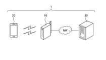
- FIG. 1 is a conceptual diagram showing an example of the overall configuration of the wireless system according to the embodiment.
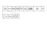
- FIG. 2 is a conceptual diagram showing a specific example of the format of the wireless frame in the wireless system according to the embodiment.
- FIG. 3 is a block diagram showing an example of the configuration of a base station included in the wireless system according to the embodiment.
- FIG. 4 is a block diagram showing an example of the function of the base station included in the wireless system according to the embodiment.
- FIG. 5 is a block diagram showing an example of the configuration of a terminal included in the wireless system according to the embodiment.
- FIG. 6 is a block diagram showing an example of the function of the terminal included in the wireless system according to the embodiment.
- FIG. 1 is a conceptual diagram showing an example of the overall configuration of the wireless system according to the embodiment.
- FIG. 2 is a conceptual diagram showing a specific example of the format of the wireless frame in the wireless system according to the embodiment.
- FIG. 3 is a block diagram showing an example of the configuration of a base station included
- FIG. 7 is a block diagram showing an example of a detailed function of the link management unit of the base station included in the wireless system according to the embodiment.
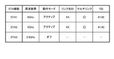
- FIG. 8 is a table showing an example of link management information in the wireless system according to the embodiment.
- FIG. 9 is a flowchart showing an example of a data transmission method at the time of multi-link in the wireless system according to the embodiment.
- FIG. 10 is a flowchart showing an example of a time synchronization method in the wireless system according to the embodiment.
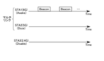
- FIG. 11 is a conceptual diagram showing an example of a beacon signal output method in a base station included in the wireless system according to the embodiment.
- FIG. 12 is a table showing an example of link management information in the wireless system according to the embodiment.
- FIG. 13 is a flowchart showing an example of a buffer notification method in a base station included in the wireless system according to the embodiment.
- FIG. 14 is a conceptual diagram showing an example of a beacon signal output method in a base station included in the wireless system according to the embodiment.
- FIG. 15 is a conceptual diagram showing a specific example of a beacon signal including TIM in the wireless system according to the embodiment.
- FIG. 16 is a flowchart showing an example of a method of starting multi-link power saving in the wireless system according to the embodiment.
- FIG. 17 is a flowchart showing an example of a method of terminating multi-link power save in the wireless system according to the embodiment.
- FIG. 18 is a flowchart showing an example of a communication method at the time of multi-link power saving in the wireless system according to the embodiment.
- FIG. 19 is a flowchart showing an example of a communication method at the time of multi-link power saving in the wireless system according to the embodiment.
- FIG. 20 is a block diagram showing an example of the function of the base station included in the wireless system according to the first modification of the embodiment.
- FIG. 21 is a block diagram showing an example of the function of the terminal provided in the wireless system according to the first modification of the embodiment.
- FIG. 22 is a table showing an example of link management information in the wireless system according to the second modification of the embodiment.
- FIG. 23 is a conceptual diagram showing an example of a beacon signal output method in a base station provided in the wireless system according to the second modification of the embodiment.
- FIG. 24 is a conceptual diagram showing an example of a frequency band used for wireless communication in the wireless system according to the third modification of the embodiment.
- FIG. 25 is a table showing an example of link management information in the wireless system according to the third modification of the embodiment.
- the wireless system 1 according to the embodiment will be described below with reference to the drawings.
- the embodiments exemplify devices and methods for embodying the technical idea of the invention.
- the drawings are schematic or conceptual. The dimensions and ratios of each drawing are not always the same as the actual ones.
- the technical idea of the present invention is not specified by the shape, structure, arrangement, etc. of the constituent elements. Further, in the following description, components having substantially the same function and configuration are designated by the same reference numerals.
- FIG. 1 shows an example of the configuration of the wireless system 1 according to the embodiment.
- the wireless system 1 includes, for example, a base station 10, a terminal 20, and a server 30.
- the base station 10 is connected to the network NW and is used as a wireless LAN access point.
- the base station 10 can wirelessly distribute the data received from the network NW to the terminal 20.
- the base station 10 may be connected to the terminal 20 by using one kind of band or a plurality of kinds of bands.
- the wireless connection between the base station 10 and the terminal 20 using a plurality of types of bands is referred to as "multi-link".
- the communication between the base station 10 and the terminal 20 is based on, for example, the 802.11 standard.
- the terminal 20 is a wireless terminal such as a smartphone or a tablet PC.
- the terminal 20 can send and receive data to and from the server 30 on the network NW via the base station 10 wirelessly connected.
- the terminal 20 may be another electronic device such as a desktop computer or a laptop computer.
- the terminal 20 may be any device that can communicate with at least the base station 10 and can execute the operation described later.
- the server 30 can hold various information, for example, holds content data for the terminal 20.
- the server 30 is connected to, for example, a network NW by wire, and is configured to be able to communicate with the base station 10 via the network NW.
- the server 30 may be capable of communicating with at least the base station 10. That is, the communication between the base station 10 and the server 30 may be wired or wireless.
- the data communication between the base station 10 and the terminal 20 is based on the OSI (Open Systems Interconnection) reference model.
- OSI Open Systems Interconnection
- the communication function has 7 layers (1st layer: physical layer, 2nd layer: data link layer, 3rd layer: network layer, 4th layer: transport layer, 5th layer: session layer, 6th layer. Layer: presentation layer, 7th layer: application layer).
- the data link layer includes, for example, an LLC (Logical Link Control) layer and a MAC (Media Access Control) layer.
- the LLC layer forms an LLC packet by adding a DSAP (Destination Service Access Point) header, a SSAP (Source Service Access Point) header, or the like to data input from, for example, a higher-level application.
- the MAC layer adds a MAC header to, for example, an LLC packet to form a MAC frame.
- FIG. 2 shows a specific example of the format of the wireless frame used for communication between the base station 10 and the terminal 20 in the wireless system 1 according to the embodiment.
- the radio frame includes, for example, a Frame Control field, a Duration field, an Address1 field, an Address2 field, an Address3 field, a SequenceControl field, other control information fields, a Frame Body field, and an FCS (Frame Check Sequence) field. Includes.
- the Frame Control field to other control information fields correspond to, for example, the MAC header included in the MAC frame.
- the FrameBody field corresponds to, for example, the MAC payload contained in the MAC frame.
- the FCS field stores an error detection code between the MAC header and the Frame Body field, and is used to determine the presence or absence of an error in the radio frame.
- the Frame Control field indicates various control information, and includes, for example, a Type value, a Subtype value, a ToDS (ToDistributionSystem) value, and a FromDS value.
- the Type value indicates the frame type of the radio frame. For example, the Type value “00” indicates that the radio frame is a management frame. The Type value “01” indicates that the radio frame is a control frame. The Type value "10" indicates that the radio frame is a data frame.
- the content of the wireless frame changes depending on the combination of Type value and Subtype value. For example, "00/1000 (Type value / Subtype value)” indicates that the radio frame is a beacon signal.
- the meanings of the To DS value and From DS value differ depending on the combination. For example, “00 (To DS / From DS)” indicates that the data is between terminals in the same IBSS (Independent Basic Service Set). “10” indicates that the data frame is directed to the DS (Distribution System) from the outside. “01” indicates that the data frame goes out of the DS. “11” is used when configuring a mesh network.
- the Duration field indicates the planned period for using the wireless line.
- the plurality of Address fields indicate a BSSID, a source address, a destination address, a sender terminal address, a receiver terminal address, and the like.
- the SequenceControl field shows the sequence number of the MAC frame and the fragment number for the fragment.
- Other control information fields include, for example, traffic type (TID) information.
- TID information may be inserted at other locations within the radio frame.
- the Frame Body field contains information according to the type of frame. For example, the FrameBody field stores data when it corresponds to a data frame.
- FIG. 3 shows an example of the configuration of the base station 10 included in the wireless system 1 according to the embodiment.
- the base station 10 includes, for example, a CPU (Central Processing Unit) 11, a ROM (Read Only Memory) 12, a RAM (Random Access Memory) 13, a wireless communication module 14, and a wired communication module 15.
- a CPU Central Processing Unit
- ROM Read Only Memory
- RAM Random Access Memory
- the CPU 11 is a circuit capable of executing various programs, and controls the overall operation of the base station 10.
- the ROM 12 is a non-volatile semiconductor memory, and holds a program, control data, and the like for controlling the base station 10.
- the RAM 13 is, for example, a volatile semiconductor memory and is used as a working area of the CPU 11.
- the wireless communication module 14 is a circuit used for transmitting and receiving data by a wireless signal, and is connected to an antenna. Further, the wireless communication module 14 includes, for example, a plurality of communication modules corresponding to a plurality of frequency bands.
- the wired communication module 15 is a circuit used for transmitting and receiving data by a wired signal, and is connected to a network NW.
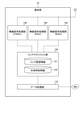
- FIG. 4 shows an example of the functional configuration of the base station 10 included in the wireless system 1 according to the embodiment.
- the base station 10 includes, for example, a data processing unit 110, a link management unit 120, and radio signal processing units 130, 140, and 150.
- the processing of the data processing unit 110, the link management unit 120, and the wireless signal processing units 130, 140, and 150 is realized by, for example, the CPU 11 and the wireless communication module 14.
- the data processing unit 110 can execute the processing of the LLC layer and the processing of the upper layer (third layer to the seventh layer) with respect to the input data. For example, the data processing unit 110 outputs the data input from the server 30 via the network NW to the link management unit 120. Further, the data processing unit 110 transmits the data input from the link management unit 120 to the server 30 via the network NW.
- the link management unit 120 executes a part of the processing of the MAC layer for the input data. Further, the link management unit 120 manages the link with the terminal 20 based on the notifications from the radio signal processing units 130, 140 and 150.
- the link management unit 120 holds the link management information 121 and the shared time information 122.
- the link management information 121 includes, for example, information of a terminal 20 stored in a RAM 13 and wirelessly connected to the base station 10.
- the shared time information 122 holds the time information shared within the base station 10 and can be referred to by each of the radio signal processing units 130, 140 and 150.
- the shared time information 122 corresponds to the time information for synchronizing the multilinks.
- Each of the wireless signal processing units 130, 140 and 150 transmits and receives data between the base station 10 and the terminal 20 using wireless communication. For example, each of the wireless signal processing units 130, 140, and 150 creates a wireless frame by adding a preamble, a PHY header, or the like to the data input from the link management unit 120. Then, each of the radio signal processing units 130, 140, and 150 converts the radio frame into a radio signal and distributes the radio signal via the antenna of the base station 10. Further, each of the radio signal processing units 130, 140, and 150 converts the radio signal received via the antenna of the base station 10 into a radio frame. Then, each of the radio signal processing units 130, 140, and 150 outputs the data contained in the radio frame to the link management unit 120.
- each of the radio signal processing units 130, 140, and 150 can execute, for example, a part of the processing of the MAC layer and the processing of the first layer on the input data or the radio signal.
- the radio signal processing unit 130 handles a radio signal in the 2.4 GHz band.
- the radio signal processing unit 140 handles radio signals in the 5 GHz band.
- the radio signal processing unit 150 handles a radio signal in the 6 GHz band.
- the radio signal processing units 130, 140 and 150 may or may not share the antenna of the base station 10.
- the wireless signal processing unit 130 holds the time information 131.
- the time information 131 is used as a reference time for communication using the radio signal processing unit 130.
- the radio signal processing unit 140 holds the time information 141.
- the time information 141 is used as a reference time for communication using the radio signal processing unit 140.
- the radio signal processing unit 150 holds the time information 151.
- the time information 151 is used as a reference time for communication using the radio signal processing unit 150.
- the link management unit 120 appropriately synchronizes the shared time information 122 with each of the time information 131, 141, and 151.
- FIG. 5 shows an example of the configuration of the terminal 20 included in the wireless system 1 according to the embodiment.
- the terminal 20 includes, for example, a CPU 21, a ROM 22, a RAM 23, a wireless communication module 24, a display 25, and a storage 26.
- the CPU 21 is a circuit capable of executing various programs, and controls the overall operation of the terminal 20.
- the ROM 22 is a non-volatile semiconductor memory, and holds a program, control data, and the like for controlling the terminal 20.
- the RAM 23 is, for example, a volatile semiconductor memory and is used as a working area of the CPU 21.
- the wireless communication module 24 is a circuit used for transmitting and receiving data by a wireless signal, and is connected to an antenna. Further, the wireless communication module 24 includes, for example, a plurality of communication modules corresponding to a plurality of frequency bands.
- the display 25 displays, for example, a GUI (Graphical User Interface) corresponding to the application software.
- the display 25 may have a function as an input interface of the terminal 20.
- the storage 26 is a non-volatile storage device, and holds, for example, the system software of the terminal 20.
- the terminal 20 does not have to be provided with a display. For example, in an IoT terminal, the display 25 may be
- FIG. 6 shows an example of the functional configuration of the terminal 20 included in the wireless system 1 according to the embodiment.
- the terminal 20 includes, for example, a data processing unit 210, a link management unit 220, a radio signal processing unit 230, 240 and 250, and an application execution unit 260.
- the processing of the data processing unit 210, the link management unit 220, and the wireless signal processing units 230, 240, and 250 is realized by, for example, the CPU 21 and the wireless communication module 24.
- the data processing unit 210 can execute the processing of the LLC layer and the processing of the upper layer (third layer to the seventh layer) with respect to the input data. For example, the data processing unit 210 outputs the data input from the application execution unit 260 to the link management unit 220. Further, the data processing unit 210 outputs the data input from the link management unit 220 to the application execution unit 260.
- the link management unit 220 can execute a part of the processing of the MAC layer for the input data. Further, the link management unit 220 manages the link with the base station 10 based on the notifications from the radio signal processing units 230, 240 and 250.
- the link management unit 220 includes the link management information 221 and the shared time information 222.
- the link management information 221 is stored in, for example, the RAM 23, and includes information on the base station 10 to which the terminal 20 is connected.
- the shared time information 222 has time information shared within the terminal 20, and can be referred to by each of the radio signal processing units 230, 240, and 250.
- the shared time information 222 corresponds to the time information for synchronizing the multilinks.
- Each of the wireless signal processing units 230, 240, and 250 transmits and receives data between the base station 10 and the terminal 20 using wireless communication.
- each of the wireless signal processing units 230, 240, and 250 creates a wireless frame by adding a preamble, a PHY header, or the like to the data input from the link management unit 220.
- each of the radio signal processing units 230, 240, and 250 converts the radio frame into a radio signal and distributes the radio signal via the antenna of the terminal 20.
- each of the wireless signal processing units 230, 240, and 250 converts the wireless signal received via the antenna of the terminal 20 into a wireless frame.
- each of the radio signal processing units 230, 240, and 250 outputs the data contained in the radio frame to the link management unit 220.
- each of the radio signal processing units 230, 240, and 250 can execute, for example, a part of the processing of the MAC layer and the processing of the first layer on the input data or the radio signal.
- the radio signal processing unit 230 handles a radio signal in the 2.4 GHz band.
- the radio signal processing unit 240 handles radio signals in the 5 GHz band.
- the radio signal processing unit 250 handles a radio signal in the 6 GHz band.
- the wireless signal processing units 230, 240 and 250 may or may not share the antenna of the terminal 20.
- the wireless signal processing unit 230 holds the time information 231.
- the time information 231 is used as a reference time for communication using the radio signal processing unit 230.
- the radio signal processing unit 240 holds the time information 241.
- the time information 241 is used as a reference time for communication using the radio signal processing unit 240.
- the radio signal processing unit 250 holds the time information 251.
- the time information 251 is used as a reference time for communication using the radio signal processing unit 250.
- the link management unit 220 appropriately synchronizes the shared time information 222 with each of the time information 231, 241 and 251.
- the application execution unit 260 executes an application that can use the data input from the data processing unit 210. For example, the application execution unit 260 can display the information of the application on the display 25. Further, the application execution unit 260 may operate based on the operation of the input interface.
- the wireless signal processing units 130, 140 and 150 of the base station 10 are configured to be connectable to the wireless signal processing units 230, 240 and 250 of the terminal 20, respectively. That is, the wireless signal processing units 130 and 230 can be wirelessly connected using the 2.4 GHz band.
- the wireless signal processing units 140 and 240 may be wirelessly connected using the 5 GHz band.
- the wireless signal processing units 150 and 250 may be wirelessly connected using the 6 GHz band.
- each radio signal processing unit may be referred to as a “STA function”. That is, the wireless system 1 according to the embodiment has a plurality of STA functions.
- FIG. 7 shows the details of the channel access function in the link management unit 120 of the base station 10 included in the wireless system 1 according to the embodiment. Since the function of the link management unit 220 of the terminal 20 is the same as that of the link management unit 120 of the base station 10, for example, the description thereof will be omitted.
- the link management unit 120 includes, for example, a data categorization unit 123, transmission queues 124A, 124B, 124C, 124D and 124E, and a CSMA / CA (Carrier Sense Multiple Access with Collision Avoidance) execution unit 125A, 125B, 125C. , 125D and 125E, and a data collision management unit 126.
- a data categorization unit 123 transmission queues 124A, 124B, 124C, 124D and 124E
- CSMA / CA Carrier Sense Multiple Access with Collision Avoidance
- the data categorization unit 123 categorizes the data input from the data processing unit 110.
- As the data category for example, "LL (Low Latency)”, “VO (Voice)”, “VI (Video)”, “BE (Best Effort)”, and “BK (Background)” are set. LL is applied to data that requires low delay. Therefore, it is preferable that the LL data is processed in preference to any of the VO, VI, BE and BK data.
- the data categorization unit 123 inputs the categorized data to any of the transmission queues 124A, 124B, 124C, 124D, and 124E.
- the LL data is input to the transmission queue 124A.
- the VO data is input to the transmission queue 124B.
- the VI data is input to the transmission queue 124C.
- BE data is input to the transmission queue 124D.
- the BK data is input to the transmission queue 124E.
- the input data of each category is accumulated in any of the corresponding transmission queues 124A to E.
- Each of the CSMA / CA execution units 125A, 125B, 125C, 125D and 125E uses preset access parameters while confirming that the carrier sense does not transmit radio signals from other terminals or the like in CSMA / CA. Wait for transmission for the specified time. Then, the CSMA / CA execution units 125A, 125B, 125C, 125D and 125E extract data from the transmission queues 124A, 124B, 124C, 124D and 124E, respectively, and process the extracted data via the data collision management unit 126. Output to at least one of units 130, 140 and 150. Then, the radio signal including the data is transmitted by the radio signal processing unit (STA function) whose transmission right has been acquired by CSMA / CA.
- STA function radio signal processing unit
- the CSMA / CA execution unit 125A executes CSMA / CA for the LL data held in the transmission queue 124A.
- the CSMA / CA execution unit 125B executes CSMA / CA for the VO data held in the transmission queue 124B.
- the CSMA / CA execution unit 125C executes CSMA / CA for the VI data held in the transmission queue 124C.
- the CSMA / CA execution unit 125D executes CSMA / CA for the BE data held in the transmission queue 124D.
- the CSMA / CA execution unit 125D executes CSMA / CA for the BK data held in the transmission queue 124E.
- Access parameters are assigned so that the transmission of radio signals is prioritized in the order of, for example, LL, VO, VI, BE, and BK.
- Access parameters include, for example, CWmin, CWmax, AIFS, TXOPLimit.
- CWmin and CWmax indicate the minimum value and the maximum value of the contention window, which is the transmission waiting time for avoiding conflict, respectively.
- AIFS Aribitration InterFrame Space
- TXOPLimit indicates an upper limit value of TXOP (Transmission Opportunity) corresponding to the occupation time of the channel.
- the priority of the transmission queue 124 becomes higher as the AIFS is smaller.
- the amount of data transmitted with one transmission right increases as the value of TXOP Limit increases.
- the data collision management unit 126 prevents data collisions when a plurality of CSMA / CA execution units 125 acquire transmission rights with the same STA function. Specifically, the data collision management unit 126 adjusts the transmission timing of the data in which the transmission right is acquired by the same STA function in different categories, and transmits the data in the high priority category to the STA function.
- the STA function acquired by the CSMA / CA of the transmission queue 124A of the LL may be the same as the STA function acquired the transmission right by the CSMA / CA of any of the other transmission queues 124B to 124E. ..
- the data collision management unit 126 preferentially transmits the data stored in the transmission queue 124A to the STA function.
- data is transmitted in the order based on the priority set in the category. This prevents collisions between data to which transmission is assigned to the same STA function.
- each STA function may implement the channel access function.
- each STA function detects the state (idle / busy) of the radio channel in the corresponding link, and the link management unit determines whether or not data can be transmitted (which link). Send using, etc.).
- each STA function may independently execute carrier sense and transmit data.
- the channel access when a plurality of links are used at the same time may be executed by standardizing the access parameters by exchanging between the plurality of STA functions, and the access parameters are standardized by the link management unit. It may be executed by.
- the base station 10 and the terminal 20 can use a plurality of links at the same time by transmitting data among the plurality of STA functions based on common access parameters.
- a multi-link between the base station 10 and the terminal 20 can be established in response to a request from the base station 10 or the terminal 20.
- a multi-link between the base station 10 and the terminal 20 can be established in response to a request from the base station 10 or the terminal 20.
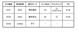
- FIG. 8 shows an example of the link management information 121 in the wireless system 1 according to the embodiment. Since the link management information 221 of the terminal 20 has information similar to the link management information 121 of the base station 10, the description thereof will be omitted. As shown in FIG. 8, the link management information 121 includes, for example, STA function, frequency band, operation mode, link destination ID, presence / absence of multilink, and TID.
- STA1 corresponds to the STA function using the frequency band of 6 GHz, that is, the radio signal processing unit 150 or 250.
- STA2 corresponds to the STA function using the frequency band of 5 GHz, that is, the radio signal processing unit 140 or 240.
- STA3 corresponds to the STA function using the frequency band of 2.4 GHz, that is, the radio signal processing unit 130 or 230.
- the operation mode indicates the current operation mode of the STA function.
- Examples of the operation mode of the STA function include an active mode, an intermittent operation mode, and an operation pause mode.
- the active mode corresponds to a state in which the STA function of the terminal 20 maintains the Awake state so that wireless signals can be transmitted and received at any time.
- the intermittent operation mode corresponds to a state in which the STA function of the terminal 20 repeats the Awake state and the Doze state to operate intermittently.
- the operation hibernation mode corresponds to a state in which transmission / reception of wireless signals is impossible by maintaining the Doze state of the STA function of the terminal 20.
- the plurality of STA functions constituting the multi-link include at least one active mode or intermittent operation mode link. The other links that make up the multilink may be set to either active mode, intermittent operation mode, or hibernation mode.
- the Awake state corresponds to the state in which wireless signals can be transmitted and received.
- the Dose state corresponds to the state in which wireless signals cannot be transmitted or received.
- the supply of power to the circuit related to the STA function is appropriately cut off. Therefore, the power consumption of the STA function decreases in the order of active mode, intermittent operation mode, and operation pause mode.
- the base station 10 or the terminal 20 can be used for communication, there may be a link between them that is not included in the multi-link link set (disabled link, corresponding to "off" in FIG. 8).
- an active mode or intermittent operation mode link that is, a communicable link is referred to as an “Awake state STA function”.
- the link in the operation hibernation mode that is, the link in the power saving state in which communication is impossible, is called the "STA function in the Dose state".
- the link destination ID corresponds to, for example, the identifier of the terminal 20 in the link management information 121, and corresponds to the identifier of the base station 10 in the link management information 221.
- a multi-link using STA1 and STA2 has been established.
- each of the link management units 120 and 220 transmits the data input from the upper layer using the link of at least one STA function associated with the multi-link.
- TID in the link management information 121 indicates the association between the STA function and the TID information.
- Each STA function sends and receives data corresponding to the assigned TID information.
- TIDs # 1 to 3 corresponds to any of LL, VO, VI, BE, and BK.
- One STA function may be associated with one traffic, that is, one TID, or a plurality of STA functions may be associated with each other. In this example, TID # 1 is assigned to both STA1 and STA2.
- TID # 2 is assigned to STA1.
- TID # 3 is assigned to STA2.
- the traffic flow corresponding to the association between the traffic and the STA function is preset at the time of setting up the multi-link between the base station 10 and the terminal 20.
- the link management unit 220 of the terminal 20 determines the correspondence between the traffic and the STA function, and requests the link management unit 120 of the base station 10. Then, when the base station 10 responds to the request, the association between the traffic and the STA function is confirmed.
- the traffic described above is set to be even among a plurality of links constituting the multi-link, for example. Not limited to this, similar types of traffic (priority / non-priority, etc.) may be collected in one of the links constituting the multilink.
- similar types of traffic for example, audio is associated with a frequency band of 2.4 GHz, and video is associated with 5 G. In this way, it is preferable that the frequency used for transmission / reception is assigned according to the type of information to be handled and the amount of data.
- FIG. 9 shows an example of a method of transmitting data at the time of multilink in the base station 10 included in the wireless system 1 according to the embodiment. As shown in FIG. 9, when the base station 10 acquires data from the upper layer, the base station 10 sequentially executes the processes of steps S10 to S12.
- the link management unit 120 acquires the TID information corresponding to the data.
- the link management unit 120 refers to the MAC header in the wireless frame acquired from the upper layer, for example, and the TID information contained in the MAC header is any of LL, VO, VI, BE, and BK. Check if. As a result, the link management unit 120 can confirm which TID the traffic flow of the data corresponds to.
- the link management unit 120 acquires the STA function corresponding to the confirmed TID information. At this time, the link management unit 120 confirms the association between the TID information and the STA function by referring to the link management information 121.
- the number of STA functions acquired by the link management unit 120 may be one or a plurality.
- the link management unit 120 outputs data to the acquired STA function.
- one STA function is associated with the output data (traffic)
- the data is transmitted serially using one STA function.
- the data is transmitted in parallel using the plurality of STA functions.
- data distribution and sorting are executed between the link management unit 120 of the base station 10 and the link management unit 220 of the terminal 20.
- the data distribution is executed by the link management unit on the transmitting side
- the sorting of the data is executed by the link management unit on the receiving side.
- the link management unit on the transmitting side adds a flag indicating that the radio frame is multi-link and an identification number to the wireless frame.
- the link management unit on the receiving side executes data sorting based on the added flag and the identification number.
- the link management unit may execute aggregation by combining the received plurality of data. Aggregation in multilink may be used as an optional feature that can be selected by the user.
- the base station 10 In the wireless system 1 according to the embodiment, it is necessary to synchronize the time in the BSS (Basic Service Set) in order to execute CSMA / CA or the like. Therefore, the base station 10 appropriately transmits a beacon signal for time synchronization with the terminal 20 forming the link.
- the base station 10 transmits a beacon signal including time information when each STA function of the terminal 20 in which the multi-link is established is in the Awake state.
- FIG. 10 shows an example of a time synchronization method in the base station 10 included in the wireless system 1 according to the embodiment. As shown in FIG. 10, the base station 10 sequentially executes the processes of steps S20 to S22 in order to synchronize the time in the BSS.
- step S20 the time information of each STA function constituting the multi-link is synchronized with the shared time information 122.
- the link management unit 120 transmits the shared time information 122 to, for example, each STA function (radio signal processing units 130, 140 and 150).
- the shared time information 122 is overwritten by the time information 131 in the radio signal processing unit 130, the time information 141 in the radio signal processing unit 140, and the time information 151 in the radio signal processing unit 150, respectively.
- each STA function constituting the multi-link creates a beacon signal including the same time information.
- the radio signal processing units 130, 140 and 150 create a beacon signal including time information 131, 141 and 151, respectively. These time information 131, 141 and 151 include the same time information by the processing of step S20.
- the link management unit 120 may create a beacon signal including the same time information and provide the created beacon signal to each STA function.
- each STA function constituting the multi-link simultaneously transmits a beacon signal.
- each STA function can transmit a beacon signal, for example, when it is in the Awake state of the active mode or when it is in the Awake state of the intermittent operation mode.
- each STA function cannot transmit a beacon signal when it is in the Disable state or in the Doze state in the intermittent operation mode.
- the present embodiment describes a mode in which a beacon signal including the same time information is simultaneously transmitted from each STA function, but the present embodiment is not limited to this.
- beacon signals including time information shared by each STA function may be transmitted at different times. That is, it suffices that the time information handled among the plurality of STA functions constituting the multi-link is synchronized, and the time information of the beacon signal is generated based on the synchronized time information.
- the beacon signal including the time information transmitted by the base station 10 as described above can be received by the terminal 20.
- the terminal 20 uses the STA function in the Awake state to receive the beacon signal.
- the link management unit 220 of the terminal 20 overwrites the time information included in the received beacon signal with the shared time information 222. That is, the time information included in the beacon signal and the shared time information 222 of the terminal 20 are synchronized. Further, the time information of the STA function used for receiving the beacon signal at this time is also synchronized with the time information included in the beacon signal.
- the STA function in the Awake state of the terminal 20 performs Fine Timing Management and the time of the received beacon signal. Add an offset to the information and overwrite the shared time information. As a result, the STA function that has transitioned from the Doze state to the Awake state can use the time information with the offset added by using the shared time information.
- Fine Timing Management is a highly accurate timing management defined by IEEE 802.11-2016.
- the terminal 20 may receive a beacon including time information by a plurality of STA functions constituting the multi-link.
- the time information of the STA function that received the beacon signal is synchronized, and the shared time information 222 is updated based on the beacon signal received by any STA function.
- the STA function used for updating the shared time information 222 is selected, for example, based on the priority set for each STA function.
- FIG. 11 shows an example of a beacon signal output method in the base station 10 included in the wireless system 1 according to the embodiment, and corresponds to the operation described with reference to FIG.
- STA1 and STA2 have established multilink. Then, each of STA1 and STA2 is set to the Awake state, and STA3 is set to the Disable state (“off”).
- each of STA1 and STA2 constituting the multi-link intermittently transmits a beacon signal.
- the transmission of the beacon signal by the STA3 in the Disable state is omitted.
- the beacon signals transmitted at the same time by each of STA1 and STA2 include the same time information (reference time information).
- the time information 131 included in the beacon signal transmitted by STA1 and the time information 141 included in the beacon signal transmitted by STA2 have the same time information synchronized with the shared time information 122. Includes.
- FIG. 12 shows an example of the link management information 121 in the wireless system 1 according to the embodiment.
- the operation mode of the STA1 is changed to the intermittent operation mode (Awake state)
- the operation mode of the STA2 is the operation pause mode (Doze). Has the information changed to state).
- the base station 10 constituting the multi-link shown in FIG. 12 transmits a beacon signal relating to the notification of the buffer status will be described.
- FIG. 13 shows an example of a buffer status notification method in the base station 10 included in the wireless system 1 according to the embodiment. As shown in FIG. 13, the base station 10 sequentially executes the processes of steps S30 to S32 in order to notify the terminal 20 of the buffer status.
- the link management unit 120 confirms the buffer status of the data corresponding to the STA function constituting the multi-link. In other words, the link management unit 120 confirms whether or not the data is accumulated in the plurality of transmission queues 124 corresponding to, for example, TIDs # 1 to 3, respectively.
- a beacon signal including TIM (Traffic Indication Map) is created based on the data buffer status.
- the TIM is an information element for notifying the terminal 20 during power saving of an incoming data.
- the creation of the beacon signal may be executed by the link management unit 120 or may be executed by each STA function. Specific examples of the format of the beacon signal including the TIM will be described later.
- the beacon signal is transmitted by configuring the multi-link and using the STA function in the Awake state.
- the base station 10 is created in step S31 by using at least one STA function in the Awake state among the STA functions in which the multilink is established when the multilink includes the STA function in the Doze state.
- Send a beacon signal the base station 10 uses the STA1 to transmit the beacon signal.
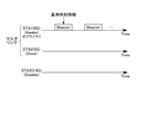
- FIG. 14 shows an example of a beacon signal output method in the base station 10 included in the wireless system 1 according to the embodiment, and corresponds to the operation described with reference to FIG. That is, in this example, STA1 and STA2 establish a multi-link, and STA1 and STA2 are set to the Awake state and the Doze state, respectively. Further, STA3 is set to the Disable state.
- the STA1 in the Awake state intermittently transmits the beacon signal.
- transmission of the beacon signal by each of the STA2 in the Doze state and the STA3 in the Disable state is omitted.
- FIG. 15 shows a specific example of a beacon signal including a TIM corresponding to the multi-link shown in FIG. 12 in the wireless system 1 according to the embodiment.
- the beacon signal includes, for example, a terminal identifier, a link identifier # 1, a buffer information # 1, a link identifier # 2, and a buffer information # 2 in this order.
- the terminal identifier includes, for example, an association identifier AID (Association Identifier) between the base station 10 and the terminal 20.
- Link identifiers # 1 and 2 include one and the other link identifiers constituting the multilink, respectively.
- the buffer statuses # 1 and 2 indicate the traffic buffer statuses corresponding to the link identifiers # 1 and 2, respectively. For example, if the buffer status is "0", it means that the traffic for the associated link identifier is not accumulated. When the buffer status is "1", it indicates that the traffic for the associated link identifier is accumulated. It should be noted that the bit indicating the buffer status and the allocation of the presence / absence of accumulation of traffic can be arbitrarily changed.
- the base station 10 directs a beacon signal including information indicating whether or not traffic is accumulated for each link for which a multi-link is established toward the terminal 20. Can be sent.
- the beacon signal for notifying the buffer status includes the buffer status of the STA function corresponding to the STA function forming the link regardless of whether the STA function is in the Awake state or the Doze state.
- the header of the beacon signal includes information indicating how many STA function buffer status information is included in the beacon signal.
- the beacon signal may include three or more pairs of the link identifier and the buffer status corresponding to the link identifier. Also, the beacon signal may or may not contain information about unestablished links.
- the terminal 20 in the embodiment applies the operation hibernation mode to some of the links constituting the multi-link according to the communication status.
- the state of the multi-link including the link in the operation hibernation mode Doze state
- multi-link power save the state of the multi-link including the link in the operation hibernation mode
- an example of various operations related to the multi-link power save of the terminal 20 will be described.
- STA1 and STA2 of the base station 10 are also referred to as "access point AP”.
- the transmission of the radio signal to the access point AP by the STA1 and SA2 of the terminal 20 corresponds to the transmission of the radio signal to the STA1 and STA2 of the base station 10, respectively.
- STA1 and STA2 are described independently, they indicate the STA function of the terminal 20.
- FIG. 16 is a flowchart showing an example of a method of starting multi-link power saving in the wireless system 1 according to the embodiment.
- each of STA1 and STA2 is in the Awake state.
- the access point AP transmits a beacon signal to each of STA1 and STA2 of the terminal 20 (step S40).
- This beacon signal contains, for example, information indicating that the traffic of each of STA1 and STA2 is empty, and is received by each of STA1 and STA2.
- the STA1 of the terminal 20 transmits a radio signal notifying the start of the multi-link power save to the access point AP, for example, in response to an empty traffic (step S41).
- the data frame (DataFrame) of the radio signal notifying the start of the multi-link power save includes, for example, a PM (Power Management) bit in which "1" is stored.
- the link management unit 220 of the terminal 20 operates, for example, the STA2 from the active mode or the intermittent operation mode (Awake state). Transition to the hibernate mode (Doze state) (step S43). As a result, the total power consumption of STA1 and STA2 constituting the multi-link is lower than that before the use of the operation hibernation mode. In the process of step S43, it is sufficient that at least one STA function set in the Doze state exists in the plurality of STA functions constituting the multi-link.
- the terminal 20 in the wireless system 1 can transition to the multi-link power save according to the traffic state, and can suppress the power consumption of the multi-link. Then, the base station 10 sends a beacon signal including a TIM for notifying the data buffer status to the STA function of the terminal 20 in the Awake state based on the transition of the terminal 20 to the multi-link power save. Send intermittently.
- the details of the communication method between the base station 10 and the terminal 20 during the multi-link power save will be described later.
- FIG. 17 shows an example of the flow of the method of ending the multi-link power save in the wireless system 1 according to the embodiment.
- STA1 and STA2 are in the Awake state and the Doze state, respectively.
- the access point AP transmits a beacon signal to each of STA1 and STA2 of the terminal 20 (step S50).
- This beacon signal includes, for example, information requesting the terminal 20 to end the multi-link power save, and is received by the STA1 in the Awake state.
- the STA1 of the terminal 20 transmits a wireless signal notifying the end of the multi-link power save to the access point AP in response to receiving the beacon signal (step S51).
- the data frame of the radio signal notifying the end of the multi-link power save includes, for example, a PM bit containing "0".
- This beacon signal contains various information elements necessary for communication.
- the base station 10 in the wireless system 1 shifts the STA function set in the operation hibernation mode in the multilink to the active mode or the intermittent operation mode as necessary, and performs the multilink. It is possible to set a plurality of constituent STA functions so that they can communicate with each other.
- the case where the STA function in the Doze state transitions to the Awake state based on the beacon signal of the base station 10 has been illustrated, but the present invention is not limited to this.
- the terminal 20 may transition the STA function in the Doze state to the Awake state based on the operation of the user or the control of the application.
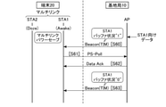
- FIG. 18 corresponds to the operation when the access point AP receives the data for STA1 in the Awake state.
- FIG. 19 corresponds to the operation when the access point AP receives the data for STA2 in the Doze state.
- the access point AP receives the data for the STA1 in the Awake state.
- the access point AP receives the data for STA1 of the terminal 20
- the data is stored in the transmission queue 124 of the link management unit 120.
- the access point AP transmits a beacon signal including a TIM indicating that the data buffer status for the STA1 is “1” to the STA1 in the Awake state (step S60).
- the beacon signal received by the STA1 of the terminal 20 is transferred to the link management unit 220.
- the link management unit 220 transmits a PS-Poll (PowerSave-Poll) frame requesting transmission of data for the STA1 to the access point AP via the STA1 based on the beacon signal (step S61).
- the access point AP receives the PS-Poll frame from the STA1 of the terminal 20, it transmits a Data ACK including the data accumulated for the STA1 to the STA1 of the terminal 20 (step S62).
- the STA1 of the terminal 20 can receive the data for its own station stored in the access point AP.
- the access point AP When the transmission of data for STA1 is completed and the accumulation of data for STA1 in the transmission queue 124 is eliminated, the access point AP includes a TIM indicating that the buffer status of the data for STA1 is "0".
- the beacon signal is transmitted to STA1 of the terminal 20 (step S63). That is, the access point AP notifies the link management unit 220 of the terminal 20 via the STA 1 that the transmission of the data for the STA 1 is completed.
- the access point AP receives the data for STA2 in the Doze state
- the data is stored in the transmission queue 124 of the link management unit 120.
- the access point AP transmits a beacon signal including a TIM indicating that the data buffer status for STA2 is “1” to STA1 in the Awake state (step S70).
- the beacon signal received by the STA1 of the terminal 20 is transferred to the link management unit 220.
- the link management unit 220 shifts the STA2 from the Doze state to the Awake state based on the beacon signal (step S71).
- the STA 2 that has transitioned to the Awake state first refers to the shared time information 222, and synchronizes the time information 241 corresponding to the STA 2 with the shared time information 222.
- the link management unit 220 transmits a PS-Poll (PowerSave-Poll) frame requesting data transmission for the STA2 to the access point AP via the STA2 (step S72).
- the access point AP receives the PS-Poll frame from the STA2 of the terminal 20, it transmits a Data ACK including the data accumulated for the STA2 to the STA2 of the terminal 20 (step S73).
- the STA2 of the terminal 20 can receive the data for its own station stored in the access point AP.
- the access point AP sends a beacon signal including a TIM indicating that the buffer status of the STA2 is “0”.
- Sent to STA1 of the terminal 20 (step S74). That is, the access point AP notifies the link management unit 220 of the terminal 20 via the STA 1 that the transmission of the data for the STA 2 is completed.
- the beacon signal may be received by the STA2.
- the link management unit 220 shifts the STA2 from the Awake state to the Doze state based on the beacon signal (step S75). That is, based on the completion of data transmission, the STA function that is not used for receiving the beacon signal among the STA functions constituting the multi-link is set to the power-saving Doze state again.
- the base station 10 in the wireless system 1 can transmit data to the terminal 20 using the multi-link power save.
- data may be transmitted in parallel to each of the plurality of STA functions constituting the multi-link.
- the link management unit 220 of the terminal 20 may instruct each of STA1 and STA2 to transmit the PS-Poll frame to the access point AP. good.
- Base stations and terminals that use wireless LAN may have a plurality of STA functions provided for each band used, for example, 2.4 GHz, 5 GHz, and 6 GHz.
- a wireless connection is established by selecting one STA function from a plurality of STA functions, and data communication between a base station and a terminal is performed.
- the unselected STA function is not used even if there is a base station corresponding to the band of the STA function.
- the wireless system 1 utilizes a plurality of STA functions provided in each of the base station 10 and the terminal 20 to establish a multi-link between the base station 10 and the terminal 20.
- a plurality of bands can be used together, and the functions of the wireless LAN device can be fully utilized.
- the wireless system 1 according to the embodiment can realize efficient communication and can improve the communication speed.
- the power consumption of the multi-link is higher than that of the single link because the base station 10 and the terminal 20 each use a plurality of STA functions.
- the wireless system 1 sets the multi-link to the multi-link power save when there is little traffic.
- the multi-link power save for example, at least one STA function among a plurality of STA functions constituting the multi-link is set to the normal state (Awake state), and the other STA functions are set to the power saving state (Doze state).
- the STA function in the Awake state can receive, for example, the beacon signal of the base station 10. Further, the STA function in the Doze state is stopped as in the Disable state, for example. Therefore, the power consumption of the STA function in the Doze state is lower than that of the STA function in the Awake state.
- the STA function in the Awake state receives a beacon signal including information corresponding to a plurality of STA functions constituting the multi-link.
- the base station 10 informs the terminal 20 that the data is accumulated via the STA function (link) in the Awake state. Notice.
- the STA function of the terminal 20 transfers the notification to the link management unit 220, and the link management unit 220 wakes up the STA function in the Doze state.
- the wake-up STA function can acquire data from the base station 10 by transmitting a PS-Poll frame.
- the time information of the STA function of the base station 10 forming the link and the STA function of the terminal 20 are synchronized with each other. You need to be. For example, when a single link is used, it is sufficient that the STA function of the base station 10 and the STA function of the terminal 20 are synchronized at least for each link, and the time information may be different between different links.
- the time synchronization in the BSS is performed by receiving the beacon signal.
- the STA function set in the active mode or the intermittent operation mode can receive the beacon and perform time synchronization.
- the STA function set to the Doze state in the multi-link power save may shift the time synchronization of the link with the passage of time. Specifically, since the STA function in the Doze state cannot synchronize the time by the beacon signal, the time information may be deviated according to the variation in the accuracy of the clock referred to by the STA function. Therefore, when the terminal 20 executes data transmission / reception with the STA function in the Doze state, it is preferable to execute the time synchronization of the STA function after wake-up.
- each of the base station 10 and the terminal 20 has a local clock common to all STA functions, that is, shared time information. Then, the base station 10 synchronously transmits the beacon signal including the shared time information at all the links constituting the multi-link, for example. Then, the STA function in the Awake state receives the beacon signal and updates the shared time information when the time stamps of the beacon signal and the local clock are different.
- the Doze state STA function uses a common local clock to perform time synchronization on the link when it wakes up. That is, the STA function in the Doze state can execute time synchronization in the multi-link without receiving the beacon signal after wake-up.
- the clock for time synchronization by multi-link is shared by each of the base station 10 and the terminal 20.
- the terminal 20 can synchronize the time between a plurality of STA functions constituting the multi-link while omitting the time synchronization for each STA function using the beacon signal.
- the wireless system 1 according to the embodiment can quickly execute data transmission / reception after wake-up of the STA function in the Doze state while suppressing the power consumption of the terminal 20.
- the wireless system 1 according to the first modified example of the embodiment has a configuration in which each STA function always refers to a common local clock.
- 20 and 21 show an example of the functions of the base station 10 and the terminal 20 included in the wireless system 1 according to the first modification of the embodiment, respectively.
- the time information 131 in the radio signal processing unit 130 and the time information 141 in the radio signal processing unit 140 from the base station 10 of the embodiment is omitted.
- the time information 231 in the radio signal processing unit 230, the time information 241 in the radio signal processing unit 240, and the radio from the terminal 20 of the embodiment has a configuration in which the time information 251 in the signal processing unit 250 is omitted.
- Other configurations of the wireless system 1 according to the first modification of the first embodiment are the same as those of the embodiment.
- each of the base station 10 and the terminal 20 does not hold the time information for each STA function.
- the clock of each STA function of the base station 10 is shared with the shared time information 122 outside the STA function.
- the clock of each STA function of the terminal 20 is shared with the shared time information 222 outside the STA function.
- each STA function can execute CSMA / CA or the like by always referring to the shared time information and operating.
- the shared time information 122 of the base station 10 and the shared time information 222 of the terminal 20 may be synchronized.
- the wireless system 1 according to the first modification of the embodiment can simplify the operation related to time synchronization as compared with the embodiment.
- FIG. 22 shows an example of the link management information 121 in the wireless system 1 according to the second modification of the embodiment.
- the link management information 121 shown in FIG. 22 is different from the link management information 121 shown in FIG. 12 in that STA1 is set as the primary link.
- the notation method of the information regarding the primary link is not limited to this, and other methods may be applied.
- the primary link is set in advance, for example, when establishing a multi-link between the base station 10 and the terminal 20.
- the STA function used for the primary link may be set in priority according to the frequency band or may be set according to the radio field strength of the link. Further, the setting of the primary link may be changed as appropriate after the establishment of the multilink. For example, the radio field strength of each link constituting the multi-link may be monitored, and the link may be appropriately changed to a link having a high radio wave strength.
- FIG. 23 shows an example of a beacon signal output method in the base station 10 included in the wireless system 1 according to the second modification of the embodiment. As shown in FIG. 23, when a primary link is set between the base station 10 and the terminal 20, the primary link is used as the basis of time synchronization.
- the primary link is always set to the Awake state, for example, the other links are set to the Doze state. ..
- the STA 1 corresponding to the primary link in the base station 10 intermittently transmits a beacon signal including the reference time information of the multi-link.
- the STA 1 corresponding to the primary link in the terminal 20 updates the shared time information 222 by using the reference time information included in the beacon signal.
- Other configurations and operations of the wireless system 1 according to the second modification of the embodiment are the same as those of the embodiment.
- the wireless system 1 according to the second modification of the embodiment can simplify the process related to the time synchronization of the multi-link as compared with the embodiment.
- the radio system 1 according to the third modified example of the embodiment establishes the same multi-link as that of the embodiment by using a plurality of channel CHs included in the same frequency band.
- the multi-link processing in the third modification of the embodiment is the same as that in which the channel used for the multi-link is changed to a plurality of channel CHs included in the same frequency band with respect to the multi-link processing of the embodiment.
- FIG. 24 shows an example of a frequency band used for wireless communication in the wireless system 1 according to the third modification of the embodiment.
- a 2.4 GHz band, a 5 GHz band, and a 6 GHz band are used in wireless communication.
- Each frequency band contains a plurality of channels.
- each of the 2.4 GHz band, 5 GHz band, and 6 GHz band contains at least three channels CH1, CH2, and CH3. Communication using each channel CH is realized by the associated STA function.
- FIG. 25 shows an example of the link management information 121 in the wireless system 1 according to the third modification of the embodiment.
- the link management information 121 in the third modification of the embodiment has a configuration in which information regarding the channel ID for each frequency band is added to the link management information 121 in the embodiment. ..
- the same multi-link as in the embodiment is established by using the channel CH2 of "STA1" corresponding to the frequency band of 6 GHz and the channel CH3 of "STA2" corresponding to the frequency band of 6 GHz. ..
- the same frequency band may be used for each STA function of the base station 10 and the terminal 20.
- the multi-link between the base station 10 and the terminal 20 may be established by a plurality of STA functions using the same frequency band.
- a plurality of STA functions may form a multi-link using, for example, different channel channels in the 5 GHz band.
- each STA function may notify the corresponding link management unit when the link cannot be maintained due to the movement of the terminal 20 or the like.
- the link management unit 220 of the terminal 20 may change the multi-link state with the link management unit 120 of the base station 10 based on the notification from the STA function. Specifically, for example, the link management unit 220 of the terminal 20 and the link management unit 120 of the base station 10 may appropriately change the STA function used in the multi-link.
- the link management units 120 and 220 update the link management information 121 and 221, respectively. Further, the link management units 120 and 220 may update the association between the traffic and the STA function according to the increase or decrease in the number of links.
- the configuration of the wireless system 1 according to the embodiment is only an example, and other configurations may be used.
- the base station 10 may include at least two radio signal processing units.
- the terminal 20 may include at least two radio signal processing units.
- the number of channels that can be processed by each STA function can be appropriately set according to the frequency band used.
- Each of the wireless communication modules 14 and 24 may support wireless communication in a plurality of frequency bands by a plurality of communication modules, or may support wireless communication in a plurality of frequency bands by one communication module.
- the functional configurations of the base station 10 and the terminal 20 in the wireless system 1 are merely examples.
- the functional configurations of the base station 10 and the terminal 20 may have other names and groups as long as they can perform the operations described in each embodiment.
- the data processing unit 110 and the link management unit 120 may be collectively referred to as a data processing unit.
- the data processing unit 210 and the link management unit 220 may be collectively referred to as a data processing unit.
- the CPU included in each of the base station 10 and the terminal 20 may be another circuit.
- MPU Micro Processing Unit
- each of the processes described in each embodiment may be realized by dedicated hardware.
- the wireless system 1 according to each embodiment may have a mixture of processes executed by software and processes executed by hardware, or may be only one of them.
- the flowchart used to explain the operation is just an example. Each operation described in the embodiment may be interchanged within the range in which the order of processing is possible, or other processing may be added. Further, the format of the wireless frame described in the above embodiment is merely an example. The radio system 1 may use other radio frame formats as long as it is possible to perform the operations described in each embodiment.
- the present invention is not limited to the above embodiment, and can be variously modified at the implementation stage without departing from the gist thereof.
- each embodiment may be carried out in combination as appropriate, in which case the combined effect can be obtained.
- the above-described embodiment includes various inventions, and various inventions can be extracted by a combination selected from a plurality of disclosed constituent requirements. For example, even if some constituent elements are deleted from all the constituent elements shown in the embodiment, if the problem can be solved and the effect is obtained, the configuration in which the constituent elements are deleted can be extracted as an invention.
- Wireless system 10 ... Base station 20 ... Terminal 30 ... Servers 11 and 21 ... CPU 12, 22 ... ROM 13, 23 ... RAM 14, 24 ... Wireless communication module 15 ... Wired communication module 25 ... Display 26 ... Storage 110, 210 ... Data processing unit 120, 220 ... Link management unit 121,221 ... Link management information 122, 222 ... Shared time information 123 ... Data categorization Unit 124 ... Transmission queue 125 ... CSMA / CA execution unit 126 ... Data collision management unit 130, 140, 150, 230, 240, 250 ... Wireless signal processing unit 131, 141, 151,231, 241,251 ... Time information
Landscapes
- Engineering & Computer Science (AREA)
- Signal Processing (AREA)
- Computer Networks & Wireless Communication (AREA)
- Mobile Radio Communication Systems (AREA)
Abstract
Description
<1-1>無線システム1の全体構成について
図1は、実施形態に係る無線システム1の構成の一例を示している。図1に示すように、無線システム1は、例えば基地局10、端末20、及びサーバ30を備えている。
図3は、実施形態に係る無線システム1の備える基地局10の構成の一例を示している。図3に示すように、基地局10は、例えばCPU(Central Processing Unit)11、ROM(Read Only Memory)12、RAM(Random Access Memory)13、無線通信モジュール14、及び有線通信モジュール15を備えている。
図5は、実施形態に係る無線システム1の備える端末20の構成の一例を示している。図5に示すように、端末20は、例えばCPU21、ROM22、RAM23、無線通信モジュール24、ディスプレイ25、及びストレージ26を備えている。
図7は、実施形態に係る無線システム1の備える基地局10のリンクマネジメント部120におけるチャネルアクセス機能の詳細を示している。尚、端末20のリンクマネジメント部220の機能は、例えば基地局10のリンクマネジメント部120と同様のため、説明を省略する。図7に示すように、リンクマネジメント部120は、例えばデータカテゴライズ部123、送信キュー124A、124B、124C、124D及び124E、CSMA/CA(Carrier Sense Multiple Access with Collision Avoidance)実行部125A、125B、125C、125D及び125E、及びデータ衝突管理部126を含んでいる。
実施形態に係る無線システム1では、基地局10及び端末20間のマルチリンクが、基地局10又は端末20からのリクエストに応じて確立され得る。以下に、実施形態に係る無線システム1において、基地局10及び端末20がマルチリンクを確立している場合の動作の一例について説明する。
(マルチリンク時のデータの送信方法について)
図9は、実施形態に係る無線システム1の備える基地局10におけるマルチリンク時のデータの送信方法の一例を示している。図9に示すように、基地局10は、上位層からデータを取得すると、ステップS10~S12の処理を順に実行する。
実施形態に係る無線システム1では、CSMA/CA等を実行するために、BSS(Basic Service Set)内で時刻が同期される必要がある。そこで、基地局10は、リンクを形成する端末20との間で時刻同期をするためのビーコン信号を適宜送信する。以下に、マルチリンクが確立された端末20の各STA機能がAwake状態である場合に、基地局10が時刻情報を含むビーコン信号を送信する一例について説明する。
実施形態における基地局10は、マルチリンクが動作休止モードのリンク(Dose状態のSTA機能)を含む場合に、データのバッファ状況を通知するビーコン信号を端末20に適宜送信する。図12は、実施形態に係る無線システム1におけるリンク管理情報121の一例を示している。図12に示されたリンク管理情報121は、図8に示されたリンク管理情報121において、STA1の動作モードが間欠動作モード(Awake状態)に変更され、STA2の動作モードが動作休止モード(Doze状態)に変更された情報を有している。以下に、図12に示されたマルチリンクを構成する基地局10がバッファ状況の通知に関するビーコン信号を送信する一例について説明する。
実施形態における端末20は、通信状況に応じて、マルチリンクを構成する一部のリンクに動作休止モードを適用する。以下では、動作休止モード(Doze状態)のリンクを含むマルチリンクの状態のことを“マルチリンクパワーセーブ”と呼び、端末20のマルチリンクパワーセーブに関連する様々な動作の一例について説明する。尚、以下の説明では、基地局10及び端末20間でSTA1及びSTA2を用いたマルチリンクが確立されているものと仮定する。また、説明を簡潔にするために、基地局10のSTA1及びSTA2のことを“アクセスポイントAP”とも呼ぶ。端末20のSTA1及びSA2がアクセスポイントAPに無線信号を送信することは、それぞれ基地局10のSTA1及びSTA2に無線信号を送信することに対応している。STA1及びSTA2がそれぞれ単独で記載された場合に、これらは端末20のSTA機能のことを示している。
図16は、実施形態に係る無線システム1におけるマルチリンクパワーセーブの開始方法の一例を示すフローチャートである。尚、本動作の開始時において、STA1及びSTA2のそれぞれは、Awake状態である。図16に示すように、アクセスポイントAPは、端末20のSTA1及びSTA2のそれぞれに対してビーコン信号を送信する(ステップS40)。このビーコン信号は、例えばSTA1及びSTA2のそれぞれのトラヒックが空であることを示す情報を含み、STA1及びSTA2のそれぞれにより受信される。
図17は、実施形態に係る無線システム1におけるマルチリンクパワーセーブの終了方法の流れの一例を示している。尚、本動作の開始時において、STA1及びSTA2は、それぞれAwake状態及びDoze状態である。図17に示すように、アクセスポイントAPは、端末20のSTA1及びSTA2のそれぞれに対してビーコン信号を送信する(ステップS50)。このビーコン信号は、例えば端末20にマルチリンクパワーセーブの終了を要求する情報を含み、Awake状態のSTA1により受信される。
図18及び図19は、実施形態に係る無線システム1におけるマルチリンクパワーセーブ中の動作の流れの一例を示している。図18は、Awake状態であるSTA1向けのデータをアクセスポイントAPが受信した場合の動作に対応している。図19は、Doze状態であるSTA2向けのデータをアクセスポイントAPが受信した場合の動作に対応している。
以上で説明された実施形態に係る無線システム1に依れば、マルチリンク時における端末20の消費電力を抑制することができる。以下に、実施形態に係る無線システム1の効果の詳細について説明する。
実施形態で説明された無線システム1はあくまで一例であり、種々の変形が可能である。以下に、実施形態の第1変形例、第2変形例、及び第3変形例について順に説明する。
実施形態の第1変形例に係る無線システム1は、各STA機能が常に共通のローカルクロックを参照する構成を有する。図20及び図21は、実施形態の第1変形例に係る無線システム1の備える基地局10及び端末20の機能の一例をそれぞれ示している。
実施形態の第2変形例に係る無線システム1は、マルチリンクを構成する複数のリンクにプライマリリンクを設定する。図22は、実施形態の第2変形例に係る無線システム1におけるリンク管理情報121の一例を示している。図22に示されたリンク管理情報121は、図12に示されたリンク管理情報121に対して、STA1がプライマリリンクに設定されている点が異なっている。プライマリリンクに関する情報の表記方法としては、これに限定されず、その他の方法が適用されてもよい。
実施形態の第3変形例に係る無線システム1は、同一の周波数帯に含まれた複数のチャネルCHを用いて、実施形態と同様のマルチリンクを確立する。実施形態の第3変形例におけるマルチリンク処理は、実施形態のマルチリンク処理に対して、マルチリンクに用いるチャネルを同じ周波数帯に含まれた複数のチャネルCHに変更したものと同様である。
上記実施形態において、各STA機能は、端末20の移動等によってリンクの維持ができない場合に、対応するリンクマネジメント部に通知してもよい。また、端末20のリンクマネジメント部220は、STA機能からの通知に基づいて、基地局10のリンクマネジメント部120との間でマルチリンクの状態を変更してもよい。具体的には、例えば端末20のリンクマネジメント部220と基地局10のリンクマネジメント部120は、マルチリンクで使用するSTA機能を適宜変更してもよい。マルチリンクの状態が変更された場合、リンクマネジメント部120及び220は、リンク管理情報121及び221をそれぞれ更新する。また、リンクマネジメント部120及び220は、リンク数の増減に応じて、トラヒックとSTA機能との関連付けを更新してもよい。
10…基地局
20…端末
30…サーバ
11,21…CPU
12,22…ROM
13,23…RAM
14,24…無線通信モジュール
15…有線通信モジュール
25…ディスプレイ
26…ストレージ
110,210…データ処理部
120,220…リンクマネジメント部
121,221…リンク管理情報
122,222…共有時刻情報
123…データカテゴライズ部
124…送信キュー
125…CSMA/CA実行部
126…データ衝突管理部
130,140,150,230,240,250…無線信号処理部
131,141,151,231,241,251…時刻情報
Claims (10)
- 第1のチャネルを用いて無線信号を送受信可能に構成された第1の無線信号処理部と、
前記第1のチャネルと異なる第2のチャネルを用いて無線信号を送受信可能に構成された第2の無線信号処理部と、
マルチリンクを同期するための共有時刻情報を格納するリンクマネジメント部と、を備え、
前記リンクマネジメント部が、前記第1の無線信号処理部と前記第2の無線信号処理部とを用いて端末とのマルチリンクを確立し、前記マルチリンクが確立されている間に、前記共有時刻情報を含むビーコン信号を前記第1の無線信号処理部と前記第2の無線信号処理部とのそれぞれに送信させる、基地局。 - 前記第1の無線信号処理部と前記第2の無線信号処理部とのそれぞれは、前記共有時刻情報を含む前記ビーコン信号を同時に送信する、
請求項1に記載の基地局。 - 前記リンクマネジメント部が、前記マルチリンクのうち前記第2の無線信号処理部を用いたリンクが動作休止モードに設定されたことを検知した後に、前記共有時刻情報を含む前記ビーコン信号を、前記第1の無線信号処理部に送信させる、
請求項1に記載の基地局。 - 前記リンクマネジメント部が、前記マルチリンクのうち前記第2の無線信号処理部を用いたリンクが動作休止モードに設定したことを検知した後に、前記第1の無線信号処理部を使用する前記端末の第1のトラヒックの情報と前記第2の無線信号処理部を使用する前記端末の第2のトラヒックの情報とを含むビーコン信号を、前記第1の無線信号処理部に送信させる、
請求項1に記載の基地局。 - 前記リンクマネジメント部が、前記第2の無線信号処理部を使用する前記第2のトラヒックが蓄積されていることを示す情報を含むビーコン信号を前記第1の無線信号処理部に送信させると、前記第2の無線信号処理部が、前記端末から前記第2のトラヒックの送信を要求するフレームを受信し、受信した前記フレームに基づいて前記第2のトラヒックを前記端末に送信する、
請求項4に記載の基地局。 - 第1のチャネルを用いて無線信号を送受信可能に構成された第1の無線信号処理部と、
前記第1のチャネルと異なる第2のチャネルを用いて無線信号を送受信可能に構成された第2の無線信号処理部と、
マルチリンクを同期するための共有時刻情報を格納するリンクマネジメント部と、を備え、
前記リンクマネジメント部が、前記第1の無線信号処理部と前記第2の無線信号処理部とを用いて基地局とのマルチリンクを確立し、前記マルチリンクが確立されている間に、前記マルチリンクの基準時刻情報を含むビーコン信号を前記第1の無線信号処理部と前記第2の無線信号処理部との少なくともいずれかが受信すると、受信した前記基準時刻情報と前記共有時刻情報とを同期させる、端末。 - 前記リンクマネジメント部が、前記第1の無線信号処理部と前記第2の無線信号処理部とのいずれかを用いて、動作休止モードの開始を通知する第1の無線信号を前記基地局に送信し、前記基地局から前記第1の無線信号が受信されたことを通知する第2の無線信号を受信すると、前記第2の無線信号処理部を動作休止モードに設定する、
請求項6に記載の端末。 - 前記第2の無線信号処理部が動作休止モードに設定されている間に、前記第1の無線信号処理部が前記基地局から前記基準時刻情報を含む前記ビーコン信号を受信すると、前記リンクマネジメント部が、前記基準時刻情報と前記共有時刻情報とを同期させる、
請求項7に記載の端末。 - 前記第2の無線信号処理部が動作休止モードに設定されている間に、前記第1の無線信号処理部が前記基地局から前記第2の無線信号処理部を使用するトラヒックが蓄積されていることを示す情報を含むビーコン信号を受信すると、前記リンクマネジメント部が前記第2の無線信号処理部を動作休止モードからウェイクアップさせる、
請求項6に記載の端末。 - 前記第2の無線信号処理部が動作休止モードからウェイクアップすると、前記第2の無線信号処理部が前記共有時刻情報と同期する、
請求項9に記載の端末。
Priority Applications (9)
| Application Number | Priority Date | Filing Date | Title |
|---|---|---|---|
| JP2022539790A JP7563456B2 (ja) | 2020-07-27 | 2020-07-27 | 基地局及び端末 |
| PCT/JP2020/028669 WO2022024169A1 (ja) | 2020-07-27 | 2020-07-27 | 基地局及び端末 |
| CN202511227908.0A CN121001159A (zh) | 2020-07-27 | 2020-07-27 | 基站以及终端 |
| US18/017,781 US12501382B2 (en) | 2020-07-27 | 2020-07-27 | Base station and terminal apparatus for synchronizing time in multi-link |
| CN202511226079.4A CN121001158A (zh) | 2020-07-27 | 2020-07-27 | 基站以及终端 |
| EP20947739.7A EP4192132B1 (en) | 2020-07-27 | 2020-07-27 | Base station and terminal |
| CN202080104570.9A CN116114323B (zh) | 2020-07-27 | 2020-07-27 | 基站以及终端 |
| JP2024167770A JP2024178433A (ja) | 2020-07-27 | 2024-09-26 | 基地局及び端末 |
| US19/391,172 US20260075557A1 (en) | 2020-07-27 | 2025-11-17 | Base station and terminal apparatus for synchronizing time in multi-link |
Applications Claiming Priority (1)
| Application Number | Priority Date | Filing Date | Title |
|---|---|---|---|
| PCT/JP2020/028669 WO2022024169A1 (ja) | 2020-07-27 | 2020-07-27 | 基地局及び端末 |
Related Child Applications (2)
| Application Number | Title | Priority Date | Filing Date |
|---|---|---|---|
| US18/017,781 A-371-Of-International US12501382B2 (en) | 2020-07-27 | 2020-07-27 | Base station and terminal apparatus for synchronizing time in multi-link |
| US19/391,172 Continuation US20260075557A1 (en) | 2020-07-27 | 2025-11-17 | Base station and terminal apparatus for synchronizing time in multi-link |
Publications (1)
| Publication Number | Publication Date |
|---|---|
| WO2022024169A1 true WO2022024169A1 (ja) | 2022-02-03 |
Family
ID=80037766
Family Applications (1)
| Application Number | Title | Priority Date | Filing Date |
|---|---|---|---|
| PCT/JP2020/028669 Ceased WO2022024169A1 (ja) | 2020-07-27 | 2020-07-27 | 基地局及び端末 |
Country Status (5)
| Country | Link |
|---|---|
| US (2) | US12501382B2 (ja) |
| EP (1) | EP4192132B1 (ja) |
| JP (2) | JP7563456B2 (ja) |
| CN (3) | CN121001158A (ja) |
| WO (1) | WO2022024169A1 (ja) |
Families Citing this family (2)
| Publication number | Priority date | Publication date | Assignee | Title |
|---|---|---|---|---|
| WO2021186582A1 (ja) * | 2020-03-17 | 2021-09-23 | 日本電信電話株式会社 | 基地局及び端末 |
| US20240040634A1 (en) * | 2020-08-19 | 2024-02-01 | Hyundai Motor Company | Method and device for saving power in a communication system supporting multiple links |
Citations (2)
| Publication number | Priority date | Publication date | Assignee | Title |
|---|---|---|---|---|
| WO2011108028A1 (ja) * | 2010-03-05 | 2011-09-09 | 富士通株式会社 | 無線通信システム、端末装置、及び無線通信システムにおける無線通信方法 |
| WO2014069106A1 (ja) * | 2012-11-01 | 2014-05-08 | ソニー株式会社 | 通信制御装置、プログラム、通信制御方法及び端末装置 |
Family Cites Families (6)
| Publication number | Priority date | Publication date | Assignee | Title |
|---|---|---|---|---|
| KR101297535B1 (ko) * | 2010-10-08 | 2013-08-20 | 엘지전자 주식회사 | 무선랜 시스템에서 파워 절약 방법 및 이를 지원하는 장치 |
| US9107157B2 (en) * | 2011-12-22 | 2015-08-11 | Intel Corporation | Implementing an assisted cross-protocol adaptation layer/cross-layer clock synchronization scheme |
| US10959153B2 (en) * | 2017-09-11 | 2021-03-23 | Qualcomm Incorporated | Techniques for multi-link aggregation signaling |
| US11032207B2 (en) * | 2017-11-17 | 2021-06-08 | Qualcomm Incorporated | Link aggregation with floating primary link |
| SG10201809503RA (en) * | 2018-10-26 | 2020-05-28 | Panasonic Ip Corp America | Communication Apparatus And Communication Method For Multi-Band Transmission |
| US11134542B2 (en) * | 2019-03-20 | 2021-09-28 | Intel Corporation | Multi-link discovery signaling in extremely high throughput (EHT) systems |
-
2020
- 2020-07-27 CN CN202511226079.4A patent/CN121001158A/zh active Pending
- 2020-07-27 CN CN202511227908.0A patent/CN121001159A/zh active Pending
- 2020-07-27 EP EP20947739.7A patent/EP4192132B1/en active Active
- 2020-07-27 CN CN202080104570.9A patent/CN116114323B/zh active Active
- 2020-07-27 JP JP2022539790A patent/JP7563456B2/ja active Active
- 2020-07-27 WO PCT/JP2020/028669 patent/WO2022024169A1/ja not_active Ceased
- 2020-07-27 US US18/017,781 patent/US12501382B2/en active Active
-
2024
- 2024-09-26 JP JP2024167770A patent/JP2024178433A/ja active Pending
-
2025
- 2025-11-17 US US19/391,172 patent/US20260075557A1/en active Pending
Patent Citations (2)
| Publication number | Priority date | Publication date | Assignee | Title |
|---|---|---|---|---|
| WO2011108028A1 (ja) * | 2010-03-05 | 2011-09-09 | 富士通株式会社 | 無線通信システム、端末装置、及び無線通信システムにおける無線通信方法 |
| WO2014069106A1 (ja) * | 2012-11-01 | 2014-05-08 | ソニー株式会社 | 通信制御装置、プログラム、通信制御方法及び端末装置 |
Non-Patent Citations (4)
| Title |
|---|
| IEEE STD 802.11-2016, 9.3.3.3 BEACON FRAME FORMAT'' AND ''11.1 SYNCHRONIZATION, 7 December 2016 (2016-12-07) |
| SAI (CYPRESS): "Multiband and Multichannel Operation in IEEE 802.11be", IEEE DRAFT; 11-19-1231-00-00BE-MULTIBAND-AND-MULTICHANNEL-OPERATION-IN-IEEE-802-11BE, IEEE-SA MENTOR, PISCATAWAY, NJ USA, vol. 802.11 EHT; 802.11be, no. 0, 15 July 2019 (2019-07-15), Piscataway, NJ USA , pages 1 - 20, XP068153021 * |
| See also references of EP4192132A4 |
| YONGHO SEOK (MEDIATEK): "Multi-link Operation Follow-up", IEEE DRAFT; 11-19-0979-01-00BE-MULTI-LINK-OPERATION-FOLLOW-UP, IEEE-SA MENTOR, PISCATAWAY, NJ USA, vol. 802.11 EHT; 802.11be, no. 1, 17 September 2019 (2019-09-17), Piscataway, NJ USA , pages 1 - 13, XP068153832 * |
Also Published As
| Publication number | Publication date |
|---|---|
| JP2024178433A (ja) | 2024-12-24 |
| CN116114323A (zh) | 2023-05-12 |
| CN116114323B (zh) | 2025-09-16 |
| US20230269683A1 (en) | 2023-08-24 |
| EP4192132A1 (en) | 2023-06-07 |
| CN121001158A (zh) | 2025-11-21 |
| JP7563456B2 (ja) | 2024-10-08 |
| US12501382B2 (en) | 2025-12-16 |
| CN121001159A (zh) | 2025-11-21 |
| US20260075557A1 (en) | 2026-03-12 |
| EP4192132B1 (en) | 2026-04-15 |
| JPWO2022024169A1 (ja) | 2022-02-03 |
| EP4192132A4 (en) | 2024-05-15 |
Similar Documents
| Publication | Publication Date | Title |
|---|---|---|
| JP7673861B2 (ja) | 基地局及び端末 | |
| EP4192109B1 (en) | Base station and terminal | |
| US20260075557A1 (en) | Base station and terminal apparatus for synchronizing time in multi-link | |
| JP7666707B2 (ja) | 基地局及び端末 | |
| TW202308443A (zh) | 支持無線tsn的ap mld進行資料傳輸的方法及裝置 | |
| JP7768281B2 (ja) | 端末 | |
| JP7638103B2 (ja) | 通信装置、通信装置の制御方法、およびプログラム | |
| WO2025151698A1 (en) | Power saving operations during a triggered transmission opportunity sharing procedure |
Legal Events
| Date | Code | Title | Description |
|---|---|---|---|
| 121 | Ep: the epo has been informed by wipo that ep was designated in this application |
Ref document number: 20947739 Country of ref document: EP Kind code of ref document: A1 |
|
| ENP | Entry into the national phase |
Ref document number: 2022539790 Country of ref document: JP Kind code of ref document: A |
|
| WWE | Wipo information: entry into national phase |
Ref document number: 2020947739 Country of ref document: EP |
|
| NENP | Non-entry into the national phase |
Ref country code: DE |
|
| ENP | Entry into the national phase |
Ref document number: 2020947739 Country of ref document: EP Effective date: 20230227 |
|
| WWG | Wipo information: grant in national office |
Ref document number: 202080104570.9 Country of ref document: CN |
|
| WWG | Wipo information: grant in national office |
Ref document number: 18017781 Country of ref document: US |
|
| WWG | Wipo information: grant in national office |
Ref document number: 2020947739 Country of ref document: EP |