WO2022024566A1 - 密封装置 - Google Patents
密封装置 Download PDFInfo
- Publication number
- WO2022024566A1 WO2022024566A1 PCT/JP2021/022450 JP2021022450W WO2022024566A1 WO 2022024566 A1 WO2022024566 A1 WO 2022024566A1 JP 2021022450 W JP2021022450 W JP 2021022450W WO 2022024566 A1 WO2022024566 A1 WO 2022024566A1
- Authority
- WO
- WIPO (PCT)
- Prior art keywords
- lip
- peripheral side
- sealing device
- axis
- conductive
- Prior art date
- Legal status (The legal status is an assumption and is not a legal conclusion. Google has not performed a legal analysis and makes no representation as to the accuracy of the status listed.)
- Ceased
Links
Images



Classifications
-
- F—MECHANICAL ENGINEERING; LIGHTING; HEATING; WEAPONS; BLASTING
- F16—ENGINEERING ELEMENTS AND UNITS; GENERAL MEASURES FOR PRODUCING AND MAINTAINING EFFECTIVE FUNCTIONING OF MACHINES OR INSTALLATIONS; THERMAL INSULATION IN GENERAL
- F16J—PISTONS; CYLINDERS; SEALINGS
- F16J15/00—Sealings
- F16J15/16—Sealings between relatively-moving surfaces
- F16J15/32—Sealings between relatively-moving surfaces with elastic sealings, e.g. O-rings
- F16J15/3268—Mounting of sealing rings
- F16J15/3276—Mounting of sealing rings with additional static sealing between the sealing, or its casing or support, and the surface on which it is mounted
-
- F—MECHANICAL ENGINEERING; LIGHTING; HEATING; WEAPONS; BLASTING
- F16—ENGINEERING ELEMENTS AND UNITS; GENERAL MEASURES FOR PRODUCING AND MAINTAINING EFFECTIVE FUNCTIONING OF MACHINES OR INSTALLATIONS; THERMAL INSULATION IN GENERAL
- F16J—PISTONS; CYLINDERS; SEALINGS
- F16J15/00—Sealings
- F16J15/16—Sealings between relatively-moving surfaces
- F16J15/32—Sealings between relatively-moving surfaces with elastic sealings, e.g. O-rings
- F16J15/3204—Sealings between relatively-moving surfaces with elastic sealings, e.g. O-rings with at least one lip
- F16J15/3232—Sealings between relatively-moving surfaces with elastic sealings, e.g. O-rings with at least one lip having two or more lips
-
- F—MECHANICAL ENGINEERING; LIGHTING; HEATING; WEAPONS; BLASTING
- F16—ENGINEERING ELEMENTS AND UNITS; GENERAL MEASURES FOR PRODUCING AND MAINTAINING EFFECTIVE FUNCTIONING OF MACHINES OR INSTALLATIONS; THERMAL INSULATION IN GENERAL
- F16J—PISTONS; CYLINDERS; SEALINGS
- F16J15/00—Sealings
- F16J15/16—Sealings between relatively-moving surfaces
- F16J15/32—Sealings between relatively-moving surfaces with elastic sealings, e.g. O-rings
- F16J15/324—Arrangements for lubrication or cooling of the sealing itself
-
- F—MECHANICAL ENGINEERING; LIGHTING; HEATING; WEAPONS; BLASTING
- F16—ENGINEERING ELEMENTS AND UNITS; GENERAL MEASURES FOR PRODUCING AND MAINTAINING EFFECTIVE FUNCTIONING OF MACHINES OR INSTALLATIONS; THERMAL INSULATION IN GENERAL
- F16J—PISTONS; CYLINDERS; SEALINGS
- F16J15/00—Sealings
- F16J15/16—Sealings between relatively-moving surfaces
- F16J15/32—Sealings between relatively-moving surfaces with elastic sealings, e.g. O-rings
- F16J15/3244—Sealings between relatively-moving surfaces with elastic sealings, e.g. O-rings with hydrodynamic pumping action
-
- F—MECHANICAL ENGINEERING; LIGHTING; HEATING; WEAPONS; BLASTING
- F16—ENGINEERING ELEMENTS AND UNITS; GENERAL MEASURES FOR PRODUCING AND MAINTAINING EFFECTIVE FUNCTIONING OF MACHINES OR INSTALLATIONS; THERMAL INSULATION IN GENERAL
- F16J—PISTONS; CYLINDERS; SEALINGS
- F16J15/00—Sealings
- F16J15/16—Sealings between relatively-moving surfaces
- F16J15/32—Sealings between relatively-moving surfaces with elastic sealings, e.g. O-rings
- F16J15/3284—Sealings between relatively-moving surfaces with elastic sealings, e.g. O-rings characterised by their structure; Selection of materials
Definitions
- the present invention relates to a sealing device, and more particularly to a sealing device used for a shaft.
- metal powder is generated by sliding between the shaft and the conductive brush, so that the metal powder generated from the conductive brush is prevented from scattering. It is necessary to provide a cover for this, and it is necessary to secure the installation space for this cover.
- an oil seal that seals between the through hole of the housing grounded to the vehicle body and the rotating shaft of the motor is formed from the conductive rubber, and the oil seal is formed through the conductive rubber.
- An electromagnetic noise suppression device has been proposed in which an electromagnetic noise induced in a rotating shaft is released to a metal housing by electrically conducting the housing and the rotating shaft (see, for example, Patent Document 2).
- a sealing device for hub bearings there is a bearing seal that uses a seal lip member made of a rubber material containing conductive carbon to take measures against electrical noise (see, for example, Patent Document 3).
- the conventional seal having a structure for suppressing the influence of electrical noise as described above is required to further improve the conductive performance.
- the present invention has been made in view of the above-mentioned problems, and an object thereof is that the conductive performance can be suppressed from being affected by the usage state and the usage time, the deterioration of the sealing performance can be suppressed, and the sliding performance can be suppressed. It is an object of the present invention to provide a sealing device capable of reducing resistance and further improving conductive performance.
- the sealing device is a sealing device that seals an annular space between the shaft and the outer peripheral side member, and has an annular reinforcing ring around the axis and the reinforcing ring. It is provided with an elastic body portion attached and formed of an annular conductive elastic body around the axis, conductive grease, and an annular conductive fabric around the axis, and the elastic body portion is attached to the axis.
- An annular dust strip extending toward the axis, an annular seal lip around the axis extending toward the axis provided inside the dust strip, and a gasket formed so as to be in contact with the outer peripheral side member.
- the seal lip has a lip contact surface, which is a tubular surface extending along the axis formed so as to be contactable with the shaft, and the conductive fabric has a portion.
- An inner peripheral side contact portion which is an annular portion around the axis formed so as to be in contact with the shaft, and an outer peripheral side contact portion which is an annular portion around the axis formed so as to be contactable with the outer peripheral side member.
- the conductive grease is provided so as to be present in at least a part of the lip contact surface and at least a part of the interlip space which is an annular space between the seal lip and the dust strip. It is characterized by being.
- At least one annular groove is formed around the axis on the lip contact surface.
- the elastic body portion has a tension applying member which is an annular elastic member, and the tension applying member has the lip contact surface in the seal lip. It is formed to give a tense force to press against the shaft.
- the inner peripheral side contact portion of the conductive fabric is formed in a cylindrical shape extending in the axial direction.
- the conductive fabric is attached to the elastic body portion on the outside of the dust strip.
- the sealing device it is possible to suppress the conductive performance from being affected by the usage condition and the usage time, suppress the deterioration of the sealing performance, reduce the sliding resistance, and further. It is possible to improve the conductive performance.
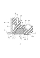
- FIG. 3 is a partially enlarged cross-sectional view showing one of the cross sections of the sealing device shown in FIG. 1 in an enlarged manner.
- FIG. 3 is a partially enlarged cross-sectional view showing an enlarged space between lips of an elastic body portion in the sealing device shown in FIG. 1. It is a partially enlarged sectional view which shows the use state of the sealing apparatus shown in FIG.
- FIG. 1 is a cross-sectional view taken along the axis x showing the configuration of the sealing device 1 according to the embodiment of the present invention.
- FIG. 2 is a partially enlarged cross-sectional view showing the configuration of the sealing device 1 according to the embodiment of the present invention.
- FIG. 2 one (upper side) of the cross section of the sealing device 1 shown in FIG. 1 is shown.
- the direction of arrow a is outside and the direction of arrow b is inside on the axis x.
- the outside is the atmosphere side where foreign substances such as dust, sand, and muddy water are present, and the inside is the space side to be sealed on the opposite side of the atmosphere side.
- the direction away from the axis x is the outer peripheral side (arrow c direction), and the direction toward the axis x is the inner peripheral side (arrow d). direction).
- the sealing device 1 is for sealing an annular space between a shaft as an inner peripheral side member (not shown) and an outer peripheral side member (not shown).
- the sealing device 1 is used, for example, as a motor driving device for an electric vehicle, as will be described later.
- the shaft is the output shaft of the electric motor
- the outer peripheral side member is a casing in which the electric motor is housed and has a through hole through which the output shaft of the electric motor penetrates.
- the inner peripheral side member may be a member that reciprocates along the axis.
- the sealing target by the sealing device 1 is not limited to the motor driving device for electric vehicles.
- the sealing device 1 can also be used for various other motor drive devices such as a motor drive unit of an in-wheel motor, a motor drive device of a hybrid vehicle, a motor drive device of an electric bike, and a motor drive device of an electric bicycle.
- the sealing device 1 has an annular reinforcing ring 10 around the axis x and an elastic body portion attached to the reinforcing ring 10 and formed of an annular conductive elastic body around the axis x. 20, a conductive grease G, and an annular conductive fabric 30 around the axis x.
- the elastic body portion 20 has an annular dust strip 21 around the axis x extending toward the axis x and an annular shape around the axis x extending inward from the dust strip 21 (on the side in the direction of arrow b) toward the axis x.
- the gasket portion 23 is formed so as to be in contact with the outer peripheral side member in a use state (hereinafter, also simply referred to as “use state”) described later in which the sealing device 1 is attached to the space between the shaft and the outer peripheral side member.
- the seal lip 22 has a lip contact surface 24 which is a cylindrical surface extending along the axis x and is formed so as to be contactable with the shaft in the use state described later.
- the conductive fabric 30 is formed so as to be in contact with the inner peripheral side contact portion 31, which is an annular portion around the axis x, which is formed so as to be in contact with the shaft in the use state described later, and the outer peripheral side member in the use state described later.
- the conductive grease G is provided so as to be present in at least a part of the lip contact surface 24 and at least a part of the interlip space S which is an annular space between the seal lip 22 and the dust strip 21.
- the configuration of the sealing device 1 will be specifically described.
- the reinforcing ring 10 is an annular metal member centered on or substantially centered on the axis x, and has a cross section along the axis x (hereinafter, also simply referred to as a “cross section”). Has an L-shaped or substantially L-shaped shape.
- the reinforcing ring 10 is, for example, a cylindrical portion 11 which is a cylindrical or substantially cylindrical portion extending in the axis x direction, and an inner peripheral side (arrow d direction side) from an end portion on the outside (arrow a direction side) of the cylindrical portion 11. ), It has a disk portion 12 which is a hollow disk-shaped portion extending to).
- the cylindrical portion 11 is formed so that the sealing device 1 can be fitted to the inner peripheral surface of the through hole formed in the outer peripheral side member (not shown), and the inside of the through hole is formed through the portion of the elastic body portion 20. It comes into contact with the peripheral surface and can be fitted.
- the cylindrical portion 11 may have a shape such that it has a pyramidal ring portion that forms a step in the middle of the cylindrical portion 11 in the axis x direction, and the cylindrical portion 11 is partially formed on the inner circumference of the through hole in the used state. It may be in contact with the surface so that it can be fitted.
- the elastic body portion 20 is attached to the reinforcing ring 10, and in the present embodiment, the elastic body portion 20 is integrally formed with the reinforcing ring 10 so as to cover the entire reinforcing ring 10.
- the elastic body portion 20 has a dust strip 21, a seal lip 22 provided inside the dust strip 21, and a gasket portion 23.
- the elastic body portion 20 has an annular lip waist portion 25 and a cover portion 26.
- the lip waist portion 25 is a portion of the reinforcing ring 10 located near the end portion on the inner peripheral side of the disk portion 12.
- the cover portion 26 is a portion attached to the disk portion 12 from the outside and the inside between the lip waist portion 25 and the gasket portion 23.
- the dust strip 21 extends diagonally outward from the lip waist 25 toward the axis x, and has a shape that shrinks in diameter toward the outside.
- the dust strip tip portion 21a which is the tip portion of the dust strip 21, is formed so that the shaft is slidably in contact with the outer peripheral surface of the shaft in the state of use of the sealing device 1.
- the seal lip 22 is located inside the dust strip 21, and extends inward from the lip waist 25 along the axis x. Further, the seal lip tip portion 22a, which is the tip portion of the seal lip 22, is an annular portion that is convex toward the inner peripheral side.
- the cross-sectional shape of the seal lip tip portion 22a is, for example, a substantially rectangular shape or a substantially trapezoidal shape as shown in FIG.
- the seal lip tip portion 22a is formed so that the shaft is slidably in contact with the outer peripheral surface of the shaft when the sealing device 1 is in use.
- the seal lip tip portion 22a has a lip contact surface 24 which is a cylindrical surface on the inner peripheral side, and the seal lip tip portion 22a is a lip in a used state.
- the shaft is slidably formed on the contact surface 24 so as to come into contact with the outer peripheral surface of the shaft.
- the lip contact surface 24 is a tubular surface, for example, as shown in FIG. 2, a cylindrical surface or a substantially cylindrical surface having an axis x as a central axis or a substantially central axis.
- the lip contact surface 24 is formed with at least one annular groove 27 around the axis x. In the present embodiment, three grooves 27 are formed as shown in FIGS. 1 and 2.
- the groove 27 is an endless annular groove, for example, a groove extending in an annular shape or a substantially annular shape centered on or substantially the center of the axis x. Further, the groove 27 is a groove forming a space recessed from the lip contact surface 24 to the outer peripheral side.
- the number of grooves 27 formed on the lip contact surface 24 is not limited to the above number.
- the groove 27 is not limited to the above-mentioned shape.
- the groove 27 may be a groove formed by one or a plurality of arcuate grooves.
- the groove 27 may be formed by arranging a plurality of arcuate grooves in an annular shape at intervals.
- the elastic body portion 20 has a tension applying member 28 which is an annular elastic member.
- the tension applying member 28 is formed so as to apply a tension force that presses the lip contact surface 24 against the shaft at the seal lip 22 in the used state.
- the tension applying member 28 is specifically a garter spring 28, and the garter spring 28 is fitted in a recess 22b formed in the seal lip 22.
- the recess 22b is a portion that is recessed toward the inner peripheral side, and is provided at a position on the outer peripheral side of the seal lip 22 that faces the tip end portion 22a of the seal lip.
- the garter spring 28 is, for example, a coil-shaped spring member made of metal, and pushes the seal lip tip 22a in the direction toward the axis x so that the lip contact surface 24 of the seal lip tip 22a is axial with respect to the displacement of the shaft. A predetermined amount of tension is applied to the seal lip tip portion 22a so as to follow the outer peripheral surface.
- the garter spring 28 is not limited to being made of metal, and may be made of various other materials such as resin.
- the gasket portion 23 is attached to the cylindrical portion 11 so as to surround the cylindrical portion 11 of the reinforcing ring 10 from the outer peripheral side and the inner peripheral side, and is a portion that covers the cylindrical portion 11 from the outer peripheral side. And an inner peripheral side gasket portion 23b which is a portion that covers the cylindrical portion 11 from the inner peripheral side.
- the outer peripheral side gasket portion 23a is compressed in the radial direction between the through hole and the cylindrical portion 11 of the reinforcing ring 10 when the sealing device 1 is press-fitted into the inner peripheral side surface (through hole) of the outer peripheral side member. Therefore, the thickness in the radial direction is set so that a fitting force, which is a force in the radial direction, is generated to a predetermined magnitude.
- Examples of the conductive elastic body of the elastic body portion 20 include conductive rubber containing a conductive filler such as carbon black particles or metal powder. Such conductive rubber contains a conductive filler and has a relatively low electric resistance.
- the volume resistivity of the conductive rubber is, for example, 108 ⁇ ⁇ cm or less. More specifically, the conductive rubber is formed by mixing an arbitrary rubber material, conductive particles, and conductive fibers in desired amounts.
- Examples of the rubber material include synthetic rubbers such as nitrile rubber (NBR), hydrogenated nitrile rubber (H-NBR), acrylic rubber (ACM), fluororubber (FKM), and silicone rubber.
- conductive metal oxides such as graphite, indium / tin oxide, and antimony / tin oxide can also be used. Further, these materials may be appropriately selected and used.
- the conductive fibers include stainless steel fibers, carbon fibers (carbon fibers, carbon tubes), and conductive fibers plated with potassium titanate. In addition, the thickness and length of the conductive fibers can be arbitrarily selected.
- the metal material of the reinforcing ring 10 examples include stainless steel and SPCC (cold rolled steel).
- the reinforcing ring 10 is manufactured by, for example, press working or forging, and the elastic body portion 20 is molded by cross-linking (vulcanization) molding using a molding die. At the time of this cross-linking molding, the reinforcing ring 10 is arranged in the molding die, the elastic body portion 20 is adhered to the reinforcing ring 10 by cross-linking adhesion, and the elastic body portion 20 and the reinforcing ring 10 are integrally formed. Will be done.
- the sealing device 1 is provided with the conductive grease G, and the conductive grease G is an annular shape between at least a part of the lip contact surface 24 and the seal lip 22 and the dust strip 21. It is provided so as to exist in at least a part of the space S between lips, which is a space.
- the conductive grease G is attached to the bottom surface 29 forming the interlip space S.
- the bottom surface 29 is a surface extending along the virtual line l shown in FIG. 3, and is a surface formed from a surface facing the inner peripheral side of each of the seal lip 22, the lip waist 25, and the dust strip 21.
- the bottom surface 29 specifically, the surface facing the inner peripheral side extending between the outer end (outer end 24a) of the lip contact surface 24 of the seal lip tip portion 22a and the dust strip tip portion 21a of the dust strip 21.
- the bottom surface 29 is a surface recessed toward the outer peripheral side.
- the inter-lip space S is an annular space surrounded by the bottom surface 29, and the boundary B on the inner peripheral side is a conical surface extending between the outer end 24a of the lip contact surface 24 and the dust strip tip 21a of the dust strip 21. It is a cylindrical surface.
- the conductive grease G is attached to the bottom surface 29 so as to fill at least a part of the interlip space S, and is provided so as not to completely fill the interlip space S as in the example shown in FIG. 3, for example. There is.
- the conductive grease G may be provided so as to fill a part of the interlip space S as described above, or may be provided so as to completely fill the interlip space S, and may be provided from the lip interlip space S. It may be provided so as to overflow. Further, the conductive grease G may be provided so as to protrude from the space S between the lips.
- the conductive grease G is also attached to a part of the lip contact surface 24 of the seal lip 22.
- the conductive grease G is applied to the entire lip contact surface 24.
- the conductive grease G is attached so as to fill the inside of the groove 27.
- the conductive grease G may be provided so as to cover a part of the lip contact surface 24 as described above, or may be provided so as to cover the entire lip contact surface 24, and may protrude from the lip contact surface 24. It may be provided as follows.
- the conductive grease G may be any grease as long as it contains a conductive substance.
- the base oil used for the conductive grease G is not particularly limited, and any oil used as a base oil for the lubricating oil can be used.
- the conductive substance may be any substance having conductivity, and the substance having conductivity is not particularly limited. As the conductive substance, a substance having good conductivity is preferable. Further, the conductive substance may be a liquid or a solid.
- the conductive substance is, for example, carbon black.
- the volume resistivity of the conductive grease G is, for example, 108 ⁇ ⁇ cm or less.
- the sealing device 1 has the conductive fabric 30.
- the conductive fabric 30 is a member made of conductive fibers, for example, a member made of a woven fabric or a non-woven fabric of conductive fibers. Examples of the conductive fibers include stainless steel fibers, carbon fibers (carbon fibers, carbon tubes), and conductive fibers plated with potassium titanate.
- the conductive fabric 30 has an inner peripheral side contact portion 31 formed so that the shaft can slidably contact the shaft in use, and an outer peripheral side contact portion 32 formed so as to be contactable with the outer peripheral side member. ing.
- the conductive fabric 30 has a hollow disk-like shape, and is, for example, a portion extending between the inner peripheral side contact portion 31 and the outer peripheral side contact portion 32. It has a certain disk portion 33.
- the disk portion 33 is a portion having an annular shape extending in a flat plate shape or a substantially flat plate shape in the radial direction, and has an inner side surface 33a and an outer side surface 33b which are a pair of annular surfaces facing each other. is doing.
- the inner peripheral side contact portion 31 extends cylindrically from the outer surface 33b at the inner peripheral side end portion (inner peripheral end portion 33c) of the disk portion 33, and the outer peripheral side contact portion 32 is the outer peripheral side of the disk portion 33.
- the outer surface 33b extends in a cylindrical shape.
- the inner peripheral side contact portion 31 is formed in a cylindrical shape or a substantially cylindrical shape having an axis x as a central axis or a substantially central axis so as to form a flange portion at the inner peripheral end portion 33c, for example, as shown in FIG. Has been done.
- the inner peripheral side contact portion 31 has a contact surface 31a which is an annular surface facing the inner peripheral side, and the contact surface 31a has a shape so that the shaft can slidably contact the shaft in the used state.
- the contact surface 31a is, for example, a cylindrical surface or a substantially cylindrical surface having an axis x as a central axis or a substantially central axis.
- the contact surface 31a of the inner peripheral side contact portion 31 is a cylindrical surface, the contact area with the shaft is large. Further, since the inner peripheral side contact portion 31 is formed in a flange shape, it is easy to follow the outer peripheral surface of the shaft with respect to the eccentricity of the shaft in the used state.
- the outer peripheral side contact portion 32 is formed in a cylindrical shape or a substantially cylindrical shape having an axis x as a central axis or a substantially central axis so as to form a flange portion at the outer peripheral end portion 33d.
- the outer peripheral side contact portion 32 has a contact surface 32a which is an annular surface facing the outer peripheral side, and the contact surface 32a has a shape capable of contacting the inner peripheral surface of the through hole of the outer peripheral side member in the used state. It has become.
- the contact surface 32a is, for example, a cylindrical surface or a substantially cylindrical surface having an axis x as a central axis or a substantially central axis. In this case, since the contact surface 32a of the outer peripheral side contact portion 32 is a cylindrical surface, the contact area with the through hole of the outer peripheral side member is large.
- the inner peripheral side contact portion 31 may have another shape as long as it can contact the shaft in the used state.
- the outer peripheral side contact portion 32 may have another shape as long as it has a shape that allows contact with the outer peripheral side member in the used state.
- the conductive fabric 30 does not have the inner peripheral side contact portion 31, and may be formed so as to be in contact with the shaft at the inner peripheral end portion 33c of the disk portion 33.
- the conductive fabric 30 does not have the outer peripheral side contact portion 32, and may be formed so as to come into contact with the outer peripheral side member at the outer peripheral end portion 33d of the disk portion 33.
- the conductive fabric 30 does not have the outer peripheral side contact portion 32, and may be formed so as not to come into contact with the outer peripheral side member at the outer peripheral end portion 33d of the disk portion 33.
- the conductive fabric 30 is fixed to the elastic body portion 20 by adhesion or the like.
- the conductive fabric 30 is attached to the elastic body portion 20 on the outer side of the dust strip 21, and as shown in FIGS. 1 and 2, for example, the cover portion 26 of the elastic body portion 20 has an inner surface 33a of the disk portion 33. Is fixed at. Therefore, in the sealing device 1, the inner peripheral side contact portion 31 and the outer peripheral side contact portion 32 of the conductive fabric 30 extend outward. Further, as described above, the conductive fabric 30 is fixed to the elastic body portion 20 so that the inner peripheral side contact portion 31 and the outer peripheral side contact portion 32 are in contact with the shaft and the outer peripheral side member respectively in the used state. ..
- the inner peripheral side contact portion 31 and the outer peripheral side contact portion 32 are fixed so as not to interfere with the elastic body portion 20. Since the conductive fabric 30 is fixed to the elastic body portion 20 in the cover portion 26, the contact area between the conductive fabric portion 30 and the elastic body portion 20 can be increased.
- the inner peripheral side contact portion 31 and the outer peripheral side contact portion 32 may extend in different directions with respect to the disk portion 33, and the inner peripheral side contact portion 31 and the outer peripheral side contact portion 32 both extend inward. May be good.
- FIG. 4 is a partially enlarged cross-sectional view of the sealing device 1 in a used state.
- FIG. 4 shows an example of the usage state of the sealing device 1, and the sealing device 1 is attached to the motor drive device 100 of the electric vehicle and is in the usage state.
- the sealing device 1 has an annular gap between the output shaft 102 of the electric motor 101 and the opening 104 forming the through hole 105 through which the output shaft 102 is inserted in the used state. It is mounted between the output shaft 102 and the opening 104 for sealing.
- the opening 104 is formed in the casing 103 of the motor drive device 100, the electric motor 101 is housed in the casing 103, and the output shaft 102 is supported by a bearing (not shown).
- Lubricating oil is sealed in the casing 103, and the sealing device 1 prevents the lubricating oil in the casing 103 from leaking to the outside, and at the same time, the casing 103 of foreign substances such as dust, sand, and muddy water from the outside. We are trying to prevent entry into the interior.
- the sealing device 1 is press-fitted and attached to the opening 104 of the casing 103, and the gasket portion 23 of the elastic body portion 20 comes into contact with the inner peripheral surface 104a of the opening 104. It is compressed between the opening 104 and the reinforcing ring 10. As a result, the space between the sealing device 1 and the opening 104 of the casing 103 is sealed. Further, the seal lip tip portion 22a of the seal lip 22 slidably contacts the outer peripheral surface 102a of the output shaft 102 on the lip contact surface 24, and the sealing device 1 and the output shaft 102 are sealed. Has been done.
- the seal lip 22 and the dust strip 21 of the elastic body portion 20 are in contact with the outer peripheral surface 102a of the output shaft 102 at the lip contact surface 24 and the dust strip tip portion 21a, respectively, and the bottom surface 29 and the output shaft 102 are in contact with each other.
- a closed space (inter-lip space S) is formed between the outer peripheral surface 102a and the outer peripheral surface 102a. Due to this contact, the seal lip 22 and the dust strip 21 are deformed, the inter-lip space S is deformed in the used state, and the volume of the inter-lip space S in the used state is in a free state not attached to the motor drive device 100. It is smaller than the volume of the space S between lips in the sealing device 1 of the above. In the state of use, neither the seal lip 22 nor the dust strip 21 may be deformed, or either of them may not be deformed.
- the lip contact surface 24 forms an annular surface, and is a cylindrical surface or a substantially cylindrical surface extending along the axis x. Therefore, the lip contact surface 24 is in contact with the outer peripheral surface 102a of the output shaft 102 with a wide width in the axis x direction. Further, the lip contact surface 24 is given a tense force with respect to the output shaft 102 by the garter spring 28. Therefore, even when the output shaft 102 is eccentric, the lip contact surface 24 follows the outer peripheral surface 102a of the output shaft 102 by the garter spring 28, and the wide contact surface of the lip contact surface 24 is maintained.
- the bottom surface 29 of the sealing device 1 is provided with the conductive grease G so as to fill a part of the space between lips S, and in the used state, at least a part of the bottom surface 29 and the output shaft 102.
- a part of the outer peripheral surface 102a is connected via the conductive grease G.
- the conductive grease G may be attached to the bottom surface 29 of the sealing device 1 so that the conductive grease G fills the space S between the lips of the sealing device 1 in the used state.
- the space S between lips is filled with the conductive grease G.
- the conductive grease G attached to the bottom surface 29 of the sealing device 1 is provided so that the conductive grease G does not expand and the volume of the conductive grease G does not become larger than the volume of the space between lips S in the used state. It is preferable that the amount is set. This is to prevent the conductive grease G from expanding and the volume of the conductive grease G becoming larger than the volume of the interlip space S in the used state. As a result, the seal lip 22 is lifted, and the contact between the lip contact surface 24 and the outer peripheral surface 102a of the output shaft 102 is prevented from being released. Similarly, it is possible to prevent the dust strip 21 from being released from contact with the outer peripheral surface 102a of the output shaft 102. Therefore, in the free-state sealing device 1, the amount of the conductive grease G attached to the bottom surface 29 is preferably an amount that does not completely fill the space between lips S.
- the conductive grease G is also attached to the lip contact surface 24 of the seal lip 22, so that the lip contact surface 24 of the seal lip 22 and the output are output in the used state.
- the conductive grease G is interposed between the outer peripheral surface 102a of the shaft 102.
- the conductive grease G is interposed between the entire surface of the lip contact surface 24 of the seal lip 22 and the outer peripheral surface 102a of the output shaft 102. Therefore, in the sealing device 1 in the free state, the conductive grease G is attached to the entire surface or substantially the entire surface of the lip contact surface 24 of the seal lip 22.
- the conductive grease G does not have to be interposed between the entire surface of the lip contact surface 24 and the outer peripheral surface 102a of the output shaft 102, and a part of the lip contact surface 24 and the output shaft 102. It may be interposed between the outer peripheral surface 102a and the outer peripheral surface 102a. Therefore, in the sealing device 1 in the free state, the conductive grease G may not be attached to the entire surface of the lip contact surface 24 of the seal lip 22.
- the conductive grease G is also present in the groove 27 of the lip contact surface 24 in the used state.
- the conductive grease G is present in the entire groove 27 of the lip contact surface 24.
- the conductive grease G does not have to be present in the entire groove 27 of the lip contact surface 24.
- the inner peripheral side contact portion 31 of the conductive fabric 30 is in contact with the outer peripheral surface 102a of the output shaft 102 on the cylindrical surface or the substantially cylindrical contact surface 31a, and the conductive fabric 30.
- the outer peripheral side contact portion 32 is in contact with the inner peripheral surface 104a of the opening 104 of the casing 103 on the cylindrical surface or the substantially cylindrical contact surface 32a.
- the sealing device 1 electrically connects the output shaft 102 and the casing 103 via the elastic body portion 20 formed of the conductive rubber, and the elastic body portion 1 is used. It is possible to secure the continuity between the output shaft 102 and the casing 103 via the 20th.
- the elastic body portion 20 forms a conduction path that electrically connects the output shaft 102 and the casing 103 in the used state. Therefore, the leak current generated in the electric motor 101 can be discharged from the output shaft 102 to the casing 103, and the generation of noise can be suppressed.
- the lip contact surface 24 of the seal lip 22 is a cylindrical or substantially cylindrical surface extending along the axis x, the lip contact surface 24 has a wide width in the axis x direction on the output shaft 102. Are in contact. Therefore, the lip contact surface 24 can improve the conductivity of the conduction path formed by the elastic body portion 20. As a result, the amount of discharge of the leak current generated in the electric motor 101 from the output shaft 102 to the casing 103 can be increased, and the generation of noise can be further suppressed.
- the lip contact surface 24 follows the output shaft 102 due to the tense force of the garter spring 28, and the posture of the lip contact surface 24 with respect to the outer peripheral surface 102a of the output shaft 102 can be maintained. Therefore, even when the output shaft 102 is eccentric or the like, it is possible to suppress a reduction in the contact area of the output shaft 102 of the lip contact surface 24 with respect to the outer peripheral surface 102a. As a result, a large contact area of the output shaft 102 of the lip contact surface 24 with respect to the outer peripheral surface 102a can be stably maintained in the used state, and the conductivity of the conduction path formed by the elastic body portion 20 can be stably maintained. It can be maintained and the generation of noise can be stably suppressed.
- the sealing device 1 is electrically connected between the output shaft 102 and the casing 103 via the conductive fabric 30, and outputs via the conductive fabric 30. It is possible to secure the continuity between the shaft 102 and the casing 103.
- the conductive fabric 30 forms a conduction path that electrically connects the output shaft 102 and the casing 103 in the used state. Therefore, in addition to the elastic body portion 20, the conductive fabric 30 can also discharge the leakage current generated in the electric motor 101 from the output shaft 102 to the casing 103, further suppressing the generation of noise. ..
- the sealing device 1 has a conduction path formed by the conductive fabric 30 in addition to the conduction path formed by the elastic body portion 20. Therefore, the amount of conduction between the output shaft 102 and the casing 103 can be increased, and the conductivity of the sealing device 1 can be improved. As a result, the amount of discharge of the leak current generated in the electric motor 101 from the output shaft 102 to the casing 103 can be increased, and the generation of noise can be further suppressed.
- the sealing device 1 has a conduction path formed by the elastic body portion 20, and can maintain the conductivity of the sealing device 1 as a whole, and noise is generated regardless of the usage condition and the usage time. The inhibitory effect can be maintained.
- the inner peripheral side contact portion 31 of the conductive fabric 30 is formed in a flange shape, it is easy to follow the outer peripheral surface 102a of the output shaft 102 with respect to the eccentricity of the output shaft 102 in the used state. Further, since the contact surface 31a of the inner peripheral side contact portion 31 of the conductive fabric 30 is a cylindrical surface or a substantially cylindrical surface, the contact area of the output shaft 102 with the outer peripheral surface 102a is large. Further, since the contact surface 32a of the outer peripheral side contact portion 32 is a cylindrical surface or a substantially cylindrical surface, the contact area of the opening 104 with the inner peripheral surface 104a is large.
- the conductive fabric 30 is fixed to the elastic body portion 20 in the cover portion 26, the contact area between the conductive fabric 30 and the elastic body portion 20 is large. Therefore, the conductive fabric 30 can increase the amount of conduction, can effectively suppress the generation of noise, can stably maintain the conductivity regardless of the usage conditions, and generate noise. The inhibitory effect of noise can be stably maintained.
- conductive grease G is provided on the lip space S and the lip contact surface 24 of the seal lip 22, and the conductive grease is provided between the elastic body portion 20 and the output shaft 102 in the used state. G intervenes.
- the intervening conductive grease G can reduce the electrical resistance between the output shaft 102 and the casing 103, and can further reduce the generation of noise.
- the sealing device 1 has two lips, a seal lip 22 and a dust strip 21, but since the conductive grease G is provided on the lip contact surface 24 and the space between lips S, the grease is lubricated. Therefore, the sliding resistance can be reduced, and the increase in the sliding resistance due to the increase in the number of lips can be suppressed.
- the lip contact surface 24 of the seal lip 22 has a large contact area and is given a tense force by the garter spring 28, so that there is a concern that the sliding resistance due to the seal lip 22 will increase.
- the lip contact surface 24 is formed with a groove 27, and the lip contact surface 24 secures the width in the axis x direction of the lip contact surface 24 in order to maintain a stable posture.
- the contact area of 24 can be reduced. Therefore, it is possible to suppress an increase in sliding resistance due to the seal lip 22.
- the conductive grease G can be held in the groove 27, the sliding resistance can be reduced by lubricating the grease, and the increase in the sliding resistance due to the seal lip 22 can be suppressed. can.
- the lip contact surface 24 has an annular surface facing the outer peripheral surface 102a of the output shaft 102 as described above. Therefore, according to the sealing device 1, unlike the conventional sealing device having a lip tip portion having a wedge-shaped cross section, for example, the sealing lip tip portion 22a is less deformed in a state of being in contact with the outer peripheral surface 102a of the output shaft 102. That is, the seal lip 22 of the sealing device 1 is excellent in durability, and in addition, the contact area with the output shaft 102 can be increased.
- the sealing device 1 itself has conductivity as described above, it is not necessary to separately prepare a metal brush or the like in order to achieve continuity between the output shaft 102 and the casing 103, and the motor drive device 100
- the configuration can be simplified and the space of the motor drive device 100 can be saved.
- the lip contact surface 24 is caused by the tense force of the garter spring 28 with respect to the outer peripheral surface 102a of the output shaft 102. Since it can be strongly pressed, the conduction state between the output shaft 102 and the casing 103 can be maintained, and the generation of noise can be stably reduced even in a low temperature environment.
- the contact area between the lip contact surface 24 of the seal lip tip portion 22a and the outer peripheral surface 102a of the output shaft 102 when the seal lip 22 of the elastic body portion 20 is sagging or worn after long-term use May be partially reduced. Even in such a case, in the sealing device 1, the posture of the lip contact surface 24 of the elastic body portion 20 with respect to the outer peripheral surface 102a of the output shaft 102 is stable due to the tense force of the garter spring 28. Since the lip contact surface 24 can be maintained in a state of being strongly pressed against the outer peripheral surface 102a of the output shaft 102, the conduction state between the output shaft 102 and the casing 103 is maintained regardless of the usage time, and the generation of noise is stable. Can be reduced to.
- the sealing device 1 As described above, according to the sealing device 1 according to the embodiment of the present invention, it is possible to suppress the conductive performance from being affected by the usage condition and the usage time, and it is possible to suppress the deterioration of the sealing performance, and the sliding The resistance can be reduced, and the conductive performance can be further improved.
- the sealing device 1 according to the embodiment of the present invention has been described above, the sealing device according to the present invention is not limited to the above-mentioned sealing device 1, and is included in the concept and claims of the present invention. Includes aspects.
- each configuration may be selectively combined as appropriate so as to solve or achieve at least a part of the above-mentioned problems and effects.
- the shape, material, arrangement, size, etc. of each component in the above embodiment can be appropriately changed according to the specific usage mode of the present invention.
- Sealing device 10 ... Reinforcing ring, 11 ... Cylindrical part, 12 ... Disk part, 20 ... Elastic body part, 21 ... Dustrip, 21a ... Dustrip tip, 22 ... Seal lip, 22a ... Seal lip tip, 22b ... recess, 23 ... gasket part, 23a ... outer peripheral side gasket part, 23b ... inner peripheral side gasket part, 24 ... lip contact surface, 24a ... outer end, 25 ... lip waist part, 26 ... cover part, 27 ... groove, 28. ... Gasket spring (tension force applying member), 29 ... bottom surface, 30 ... conductive fabric, 31 ... inner peripheral side contact portion, 31a ... contact surface, 32 ...
Landscapes
- Engineering & Computer Science (AREA)
- General Engineering & Computer Science (AREA)
- Mechanical Engineering (AREA)
- Physics & Mathematics (AREA)
- Fluid Mechanics (AREA)
- Sealing With Elastic Sealing Lips (AREA)
- Sealing Devices (AREA)
Abstract
Description
Claims (5)
- 軸と外周側部材との間を環状の空間を密封する密封装置であって、
軸線周りに環状の補強環と、
前記補強環に取り付けられ、前記軸線周りに環状の導電性の弾性体から形成された弾性体部と、
導電性グリースと、
前記軸線周りに環状の導電性ファブリックとを備え、
前記弾性体部は、前記軸線に向かって延びる前記軸線周りに環状のダストリップと、前記ダストリップより内側に設けられた前記軸線に向かって延びる前記軸線周りに環状のシールリップと、前記外周側部材に接触可能に形成されたガスケット部とを有しており、
前記シールリップは、前記軸に接触可能に形成された前記軸線に沿って延びる筒面状の面であるリップ接触面を有しており、
前記導電性ファブリックは、前記軸に接触可能に形成された前記軸線周りに環状の部分である内周側接触部と、前記外周側部材に接触可能に形成された前記軸線周りに環状の部分である外周側接触部とを有しており、
前記導電性グリースは、前記リップ接触面の少なくとも一部及び前記シールリップと前記ダストリップとの間の環状の空間であるリップ間空間の少なくとも一部に存在するように設けられていることを特徴とする密封装置。 - 前記リップ接触面には、前記軸線周りに環状の溝が少なくとも1つ形成されていることを特徴とする請求項1に記載の密封装置。
- 前記弾性体部は、環状の弾性部材である緊迫力付与部材を有しており、
前記緊迫力付与部材は、前記シールリップにおいて前記リップ接触面を前記軸に押し付ける緊迫力を付与するように形成されていることを特徴とする請求項1又は2に記載の密封装置。 - 前記導電性ファブリックの前記内周側接触部は、前記軸線方向に延びる筒状に形成されていることを特徴とする請求項1乃至3のいずれか1項記載の密封装置。
- 前記導電性ファブリックは、前記ダストリップよりも外側において前記弾性体部に取り付けられていることを特徴とする請求項1乃至4のいずれか1項記載の密封装置。
Priority Applications (3)
| Application Number | Priority Date | Filing Date | Title |
|---|---|---|---|
| JP2022540053A JP7475453B2 (ja) | 2020-07-27 | 2021-06-14 | 密封装置 |
| EP21851100.4A EP4191097A4 (en) | 2020-07-27 | 2021-06-14 | Sealing device |
| CN202180047919.4A CN115777047B (zh) | 2020-07-27 | 2021-06-14 | 密封装置 |
Applications Claiming Priority (2)
| Application Number | Priority Date | Filing Date | Title |
|---|---|---|---|
| JP2020-126832 | 2020-07-27 | ||
| JP2020126832 | 2020-07-27 |
Publications (1)
| Publication Number | Publication Date |
|---|---|
| WO2022024566A1 true WO2022024566A1 (ja) | 2022-02-03 |
Family
ID=80035364
Family Applications (1)
| Application Number | Title | Priority Date | Filing Date |
|---|---|---|---|
| PCT/JP2021/022450 Ceased WO2022024566A1 (ja) | 2020-07-27 | 2021-06-14 | 密封装置 |
Country Status (4)
| Country | Link |
|---|---|
| EP (1) | EP4191097A4 (ja) |
| JP (1) | JP7475453B2 (ja) |
| CN (1) | CN115777047B (ja) |
| WO (1) | WO2022024566A1 (ja) |
Cited By (4)
| Publication number | Priority date | Publication date | Assignee | Title |
|---|---|---|---|---|
| US20220349477A1 (en) * | 2021-05-03 | 2022-11-03 | BRUSS Sealing Systems GmbH | Radial shaft sealing ring |
| WO2023162676A1 (ja) * | 2022-02-24 | 2023-08-31 | Nok株式会社 | 密封装置 |
| JPWO2024089960A1 (ja) * | 2022-10-27 | 2024-05-02 | ||
| WO2024176537A1 (ja) * | 2023-02-24 | 2024-08-29 | 株式会社ジェイテクトシーリングテクノ | 摺動部材、及び、転がり軸受 |
Families Citing this family (1)
| Publication number | Priority date | Publication date | Assignee | Title |
|---|---|---|---|---|
| DE102023130792A1 (de) * | 2023-11-07 | 2025-05-08 | Carl Freudenberg Kg | Dichtungsanordnung mit Erdungselement |
Citations (9)
| Publication number | Priority date | Publication date | Assignee | Title |
|---|---|---|---|---|
| JPS60167263U (ja) * | 1984-04-13 | 1985-11-06 | エヌオーケー株式会社 | オイルシ−ル |
| US5195757A (en) * | 1991-06-10 | 1993-03-23 | Freudenberg-Nok General Partnership | Patterned textured seal |
| JP2000244180A (ja) | 1999-02-22 | 2000-09-08 | Toyota Motor Corp | 電気自動車の電磁ノイズ抑制装置 |
| JP2014142065A (ja) * | 2013-01-22 | 2014-08-07 | Carl Freudenberg Kg | シールリング及び該シールリングを備えるシール装置 |
| JP2015014296A (ja) | 2013-07-03 | 2015-01-22 | 内山工業株式会社 | 密封装置 |
| JP2015207534A (ja) | 2014-04-23 | 2015-11-19 | 本田技研工業株式会社 | 車両用動力伝達装置 |
| JP2016020739A (ja) * | 2014-07-11 | 2016-02-04 | カール・フロイデンベルク・カーゲーCarl FreudenbergKG | 前置シール、前置シールを有する前置シールアッセンブリおよび前置シールを有するシールリング |
| JP2017155929A (ja) * | 2015-03-09 | 2017-09-07 | Ntn株式会社 | シール付軸受 |
| WO2019131899A1 (ja) * | 2017-12-27 | 2019-07-04 | Nok株式会社 | 密封装置 |
Family Cites Families (8)
| Publication number | Priority date | Publication date | Assignee | Title |
|---|---|---|---|---|
| KR100279109B1 (ko) * | 1993-04-09 | 2001-03-02 | 후지 하루노스케 | 회전축 시일 |
| JP2005226787A (ja) * | 2004-02-13 | 2005-08-25 | Nsk Ltd | 軸受用密封装置 |
| JP2006234093A (ja) * | 2005-02-25 | 2006-09-07 | Nsk Ltd | 車輪支持用転がり軸受装置 |
| JP2009103142A (ja) * | 2007-10-19 | 2009-05-14 | Toyota Motor Corp | シール装置 |
| JP5800148B2 (ja) * | 2011-12-21 | 2015-10-28 | Nok株式会社 | エンジンリアシール |
| CN106481558B (zh) * | 2015-08-27 | 2018-11-16 | 上海伊莱茨真空技术有限公司 | 一种用于罗茨真空泵的三唇封油密封系统 |
| JP6540433B2 (ja) * | 2015-09-30 | 2019-07-10 | 日本精工株式会社 | 密封装置及び密封装置付ハブユニット軸受 |
| JPWO2019004141A1 (ja) * | 2017-06-29 | 2020-04-30 | Nok株式会社 | 密封装置 |
-
2021
- 2021-06-14 JP JP2022540053A patent/JP7475453B2/ja active Active
- 2021-06-14 WO PCT/JP2021/022450 patent/WO2022024566A1/ja not_active Ceased
- 2021-06-14 CN CN202180047919.4A patent/CN115777047B/zh active Active
- 2021-06-14 EP EP21851100.4A patent/EP4191097A4/en active Pending
Patent Citations (9)
| Publication number | Priority date | Publication date | Assignee | Title |
|---|---|---|---|---|
| JPS60167263U (ja) * | 1984-04-13 | 1985-11-06 | エヌオーケー株式会社 | オイルシ−ル |
| US5195757A (en) * | 1991-06-10 | 1993-03-23 | Freudenberg-Nok General Partnership | Patterned textured seal |
| JP2000244180A (ja) | 1999-02-22 | 2000-09-08 | Toyota Motor Corp | 電気自動車の電磁ノイズ抑制装置 |
| JP2014142065A (ja) * | 2013-01-22 | 2014-08-07 | Carl Freudenberg Kg | シールリング及び該シールリングを備えるシール装置 |
| JP2015014296A (ja) | 2013-07-03 | 2015-01-22 | 内山工業株式会社 | 密封装置 |
| JP2015207534A (ja) | 2014-04-23 | 2015-11-19 | 本田技研工業株式会社 | 車両用動力伝達装置 |
| JP2016020739A (ja) * | 2014-07-11 | 2016-02-04 | カール・フロイデンベルク・カーゲーCarl FreudenbergKG | 前置シール、前置シールを有する前置シールアッセンブリおよび前置シールを有するシールリング |
| JP2017155929A (ja) * | 2015-03-09 | 2017-09-07 | Ntn株式会社 | シール付軸受 |
| WO2019131899A1 (ja) * | 2017-12-27 | 2019-07-04 | Nok株式会社 | 密封装置 |
Non-Patent Citations (1)
| Title |
|---|
| See also references of EP4191097A4 |
Cited By (10)
| Publication number | Priority date | Publication date | Assignee | Title |
|---|---|---|---|---|
| US20220349477A1 (en) * | 2021-05-03 | 2022-11-03 | BRUSS Sealing Systems GmbH | Radial shaft sealing ring |
| US11906050B2 (en) * | 2021-05-03 | 2024-02-20 | BRUSS Sealing Systems GmbH | Radial shaft sealing ring |
| WO2023162676A1 (ja) * | 2022-02-24 | 2023-08-31 | Nok株式会社 | 密封装置 |
| JPWO2023162676A1 (ja) * | 2022-02-24 | 2023-08-31 | ||
| JP7804054B2 (ja) | 2022-02-24 | 2026-01-21 | Nok株式会社 | 密封装置 |
| EP4484805A4 (en) * | 2022-02-24 | 2026-02-18 | Nok Corp | SEALING DEVICE |
| JPWO2024089960A1 (ja) * | 2022-10-27 | 2024-05-02 | ||
| WO2024089960A1 (ja) * | 2022-10-27 | 2024-05-02 | Nok株式会社 | 導電性密封装置 |
| JP7559291B2 (ja) | 2022-10-27 | 2024-10-01 | Nok株式会社 | 導電性密封装置 |
| WO2024176537A1 (ja) * | 2023-02-24 | 2024-08-29 | 株式会社ジェイテクトシーリングテクノ | 摺動部材、及び、転がり軸受 |
Also Published As
| Publication number | Publication date |
|---|---|
| JP7475453B2 (ja) | 2024-04-26 |
| EP4191097A4 (en) | 2024-08-21 |
| CN115777047A (zh) | 2023-03-10 |
| CN115777047B (zh) | 2026-03-03 |
| JPWO2022024566A1 (ja) | 2022-02-03 |
| EP4191097A1 (en) | 2023-06-07 |
Similar Documents
| Publication | Publication Date | Title |
|---|---|---|
| US11365807B2 (en) | Sealing apparatus | |
| WO2022024566A1 (ja) | 密封装置 | |
| KR102627251B1 (ko) | 밀봉 장치 | |
| JP7437539B2 (ja) | 密封装置 | |
| JP6967155B2 (ja) | 密封装置 | |
| JP2024175009A (ja) | 導電性密封装置 | |
| US20260039078A1 (en) | Conductive structural body and conduction method | |
| CN121162689A (zh) | 导电密封结构 | |
| WO2026074896A1 (ja) | 導電性樹脂組成物、導電摺動体、及び導電構造体 |
Legal Events
| Date | Code | Title | Description |
|---|---|---|---|
| 121 | Ep: the epo has been informed by wipo that ep was designated in this application |
Ref document number: 21851100 Country of ref document: EP Kind code of ref document: A1 |
|
| ENP | Entry into the national phase |
Ref document number: 2022540053 Country of ref document: JP Kind code of ref document: A |
|
| WWE | Wipo information: entry into national phase |
Ref document number: 2021851100 Country of ref document: EP |
|
| NENP | Non-entry into the national phase |
Ref country code: DE |
|
| ENP | Entry into the national phase |
Ref document number: 2021851100 Country of ref document: EP Effective date: 20230227 |