WO2022024620A1 - 乗員拘束装置 - Google Patents
乗員拘束装置 Download PDFInfo
- Publication number
- WO2022024620A1 WO2022024620A1 PCT/JP2021/024059 JP2021024059W WO2022024620A1 WO 2022024620 A1 WO2022024620 A1 WO 2022024620A1 JP 2021024059 W JP2021024059 W JP 2021024059W WO 2022024620 A1 WO2022024620 A1 WO 2022024620A1
- Authority
- WO
- WIPO (PCT)
- Prior art keywords
- airbag
- tension
- occupant
- tension cloth
- restraint device
- Prior art date
- Legal status (The legal status is an assumption and is not a legal conclusion. Google has not performed a legal analysis and makes no representation as to the accuracy of the status listed.)
- Ceased
Links
Images





Classifications
-
- B—PERFORMING OPERATIONS; TRANSPORTING
- B60—VEHICLES IN GENERAL
- B60R—VEHICLES, VEHICLE FITTINGS, OR VEHICLE PARTS, NOT OTHERWISE PROVIDED FOR
- B60R21/00—Arrangements or fittings on vehicles for protecting or preventing injuries to occupants or pedestrians in case of accidents or other traffic risks
- B60R21/02—Occupant safety arrangements or fittings, e.g. crash pads
- B60R21/16—Inflatable occupant restraints or confinements designed to inflate upon impact or impending impact, e.g. air bags
- B60R21/23—Inflatable members
- B60R21/231—Inflatable members characterised by their shape, construction or spatial configuration
- B60R21/23138—Inflatable members characterised by their shape, construction or spatial configuration specially adapted for side protection
-
- B—PERFORMING OPERATIONS; TRANSPORTING
- B60—VEHICLES IN GENERAL
- B60R—VEHICLES, VEHICLE FITTINGS, OR VEHICLE PARTS, NOT OTHERWISE PROVIDED FOR
- B60R21/00—Arrangements or fittings on vehicles for protecting or preventing injuries to occupants or pedestrians in case of accidents or other traffic risks
- B60R21/02—Occupant safety arrangements or fittings, e.g. crash pads
- B60R21/16—Inflatable occupant restraints or confinements designed to inflate upon impact or impending impact, e.g. air bags
- B60R21/20—Arrangements for storing inflatable members in their non-use or deflated condition; Arrangement or mounting of air bag modules or components
- B60R21/207—Arrangements for storing inflatable members in their non-use or deflated condition; Arrangement or mounting of air bag modules or components in vehicle seats
-
- B—PERFORMING OPERATIONS; TRANSPORTING
- B60—VEHICLES IN GENERAL
- B60R—VEHICLES, VEHICLE FITTINGS, OR VEHICLE PARTS, NOT OTHERWISE PROVIDED FOR
- B60R21/00—Arrangements or fittings on vehicles for protecting or preventing injuries to occupants or pedestrians in case of accidents or other traffic risks
- B60R21/02—Occupant safety arrangements or fittings, e.g. crash pads
- B60R21/16—Inflatable occupant restraints or confinements designed to inflate upon impact or impending impact, e.g. air bags
- B60R21/23—Inflatable members
- B60R21/231—Inflatable members characterised by their shape, construction or spatial configuration
- B60R21/233—Inflatable members characterised by their shape, construction or spatial configuration comprising a plurality of individual compartments; comprising two or more bag-like members, one within the other
-
- B—PERFORMING OPERATIONS; TRANSPORTING
- B60—VEHICLES IN GENERAL
- B60R—VEHICLES, VEHICLE FITTINGS, OR VEHICLE PARTS, NOT OTHERWISE PROVIDED FOR
- B60R21/00—Arrangements or fittings on vehicles for protecting or preventing injuries to occupants or pedestrians in case of accidents or other traffic risks
- B60R21/02—Occupant safety arrangements or fittings, e.g. crash pads
- B60R21/16—Inflatable occupant restraints or confinements designed to inflate upon impact or impending impact, e.g. air bags
- B60R21/23—Inflatable members
- B60R21/231—Inflatable members characterised by their shape, construction or spatial configuration
- B60R21/2334—Expansion control features
- B60R21/2338—Tethers
-
- B—PERFORMING OPERATIONS; TRANSPORTING
- B60—VEHICLES IN GENERAL
- B60R—VEHICLES, VEHICLE FITTINGS, OR VEHICLE PARTS, NOT OTHERWISE PROVIDED FOR
- B60R21/00—Arrangements or fittings on vehicles for protecting or preventing injuries to occupants or pedestrians in case of accidents or other traffic risks
- B60R21/02—Occupant safety arrangements or fittings, e.g. crash pads
- B60R21/16—Inflatable occupant restraints or confinements designed to inflate upon impact or impending impact, e.g. air bags
- B60R21/23—Inflatable members
- B60R21/231—Inflatable members characterised by their shape, construction or spatial configuration
- B60R21/23138—Inflatable members characterised by their shape, construction or spatial configuration specially adapted for side protection
- B60R2021/23146—Inflatable members characterised by their shape, construction or spatial configuration specially adapted for side protection seat mounted
-
- B—PERFORMING OPERATIONS; TRANSPORTING
- B60—VEHICLES IN GENERAL
- B60R—VEHICLES, VEHICLE FITTINGS, OR VEHICLE PARTS, NOT OTHERWISE PROVIDED FOR
- B60R21/00—Arrangements or fittings on vehicles for protecting or preventing injuries to occupants or pedestrians in case of accidents or other traffic risks
- B60R21/02—Occupant safety arrangements or fittings, e.g. crash pads
- B60R21/16—Inflatable occupant restraints or confinements designed to inflate upon impact or impending impact, e.g. air bags
- B60R21/23—Inflatable members
- B60R21/231—Inflatable members characterised by their shape, construction or spatial configuration
- B60R21/233—Inflatable members characterised by their shape, construction or spatial configuration comprising a plurality of individual compartments; comprising two or more bag-like members, one within the other
- B60R2021/23324—Inner walls crating separate compartments, e.g. communicating with vents
-
- B—PERFORMING OPERATIONS; TRANSPORTING
- B60—VEHICLES IN GENERAL
- B60R—VEHICLES, VEHICLE FITTINGS, OR VEHICLE PARTS, NOT OTHERWISE PROVIDED FOR
- B60R21/00—Arrangements or fittings on vehicles for protecting or preventing injuries to occupants or pedestrians in case of accidents or other traffic risks
- B60R21/02—Occupant safety arrangements or fittings, e.g. crash pads
- B60R21/16—Inflatable occupant restraints or confinements designed to inflate upon impact or impending impact, e.g. air bags
- B60R21/23—Inflatable members
- B60R21/231—Inflatable members characterised by their shape, construction or spatial configuration
- B60R21/233—Inflatable members characterised by their shape, construction or spatial configuration comprising a plurality of individual compartments; comprising two or more bag-like members, one within the other
- B60R2021/23324—Inner walls crating separate compartments, e.g. communicating with vents
- B60R2021/23332—Inner walls crating separate compartments, e.g. communicating with vents using independent bags, one within the other
-
- B—PERFORMING OPERATIONS; TRANSPORTING
- B60—VEHICLES IN GENERAL
- B60R—VEHICLES, VEHICLE FITTINGS, OR VEHICLE PARTS, NOT OTHERWISE PROVIDED FOR
- B60R21/00—Arrangements or fittings on vehicles for protecting or preventing injuries to occupants or pedestrians in case of accidents or other traffic risks
- B60R21/02—Occupant safety arrangements or fittings, e.g. crash pads
- B60R21/16—Inflatable occupant restraints or confinements designed to inflate upon impact or impending impact, e.g. air bags
- B60R21/23—Inflatable members
- B60R21/231—Inflatable members characterised by their shape, construction or spatial configuration
- B60R21/2334—Expansion control features
- B60R21/2338—Tethers
- B60R2021/23382—Internal tether means
-
- B—PERFORMING OPERATIONS; TRANSPORTING
- B60—VEHICLES IN GENERAL
- B60R—VEHICLES, VEHICLE FITTINGS, OR VEHICLE PARTS, NOT OTHERWISE PROVIDED FOR
- B60R21/00—Arrangements or fittings on vehicles for protecting or preventing injuries to occupants or pedestrians in case of accidents or other traffic risks
- B60R21/02—Occupant safety arrangements or fittings, e.g. crash pads
- B60R21/16—Inflatable occupant restraints or confinements designed to inflate upon impact or impending impact, e.g. air bags
- B60R21/23—Inflatable members
- B60R21/231—Inflatable members characterised by their shape, construction or spatial configuration
- B60R21/2334—Expansion control features
- B60R21/2338—Tethers
- B60R2021/23386—External tether means
-
- B—PERFORMING OPERATIONS; TRANSPORTING
- B60—VEHICLES IN GENERAL
- B60R—VEHICLES, VEHICLE FITTINGS, OR VEHICLE PARTS, NOT OTHERWISE PROVIDED FOR
- B60R21/00—Arrangements or fittings on vehicles for protecting or preventing injuries to occupants or pedestrians in case of accidents or other traffic risks
- B60R21/02—Occupant safety arrangements or fittings, e.g. crash pads
- B60R21/16—Inflatable occupant restraints or confinements designed to inflate upon impact or impending impact, e.g. air bags
- B60R21/23—Inflatable members
- B60R21/231—Inflatable members characterised by their shape, construction or spatial configuration
- B60R21/2334—Expansion control features
- B60R21/2338—Tethers
- B60R2021/23386—External tether means
- B60R2021/23388—External tether means having ends which are movable or detachable during deployment
Definitions
- the present invention relates to a occupant restraint device having an airbag.
- This application claims priority based on Japanese Application No. 2020-127516 filed on July 28, 2020, and incorporates all the contents described in the Japanese application.
- the airbag device is a device that operates in an emergency such as a vehicle collision, and protects the airbag by expanding and deploying due to gas pressure to receive and restrain the occupant.
- the airbag devices There are various types of airbag devices depending on the installation location or application.
- Patent Document 1 discloses a side airbag device that is provided on both sides of a vehicle seat and expands and expands by the side of an occupant.
- the airbag in order for the airbag to expand and expand to catch the occupant, the airbag must be located at the expected position.
- a technique of adjusting the position of the expanding and expanding airbag by using a tension cloth is known. In such a technique, when the airbag expands and unfolds, a tension cloth surrounds and holds the outside of the airbag and brings it closer to the occupant side.
- the present invention has been made in view of such circumstances, and an object of the present invention is to restrain an occupant so that the tension cloth can more accurately adjust the position of the airbag when the airbag expands and expands. To provide the equipment.
- the occupant restraint device includes a tension cloth in which both ends are fixed to the upper part and the lower part of the vehicle seat, respectively, and an airbag that expands and expands at the side portion of the occupant seated on the seat is brought toward the occupant.
- the airbag is characterized in that a holding groove for holding the tension cloth is formed during expansion and deployment.
- the position of the airbag when the airbag expands and expands, the position of the airbag can be adjusted more accurately.
- FIG. 1 shows the state which the occupant restraint device which concerns on Embodiment 1 is attached to the seat of a vehicle.
- FIG. 1 shows the state which the airbag is expanded and expanded in the occupant restraint device.
- FIG. 2 shows the state which the airbag is expanded and expanded in the occupant restraint device.
- FIG. 2 shows the state which the airbag is expanded and expanded in the occupant restraint device which concerns on Embodiment 2.
- FIG. 1 It is sectional drawing of the airbag by IX-IX line of FIG. It is a vertical sectional view of the airbag by X-ray of FIG. It is a vertical sectional view of the airbag by the XI-XI line of FIG. It is a schematic diagram which shows the state which the airbag expanded and expanded in the occupant restraint device which concerns on Embodiment 3.
- FIG. It is a schematic diagram which shows the state which the airbag expanded and expanded in the occupant restraint device which concerns on Embodiment 4.
- FIG. It is a schematic diagram which shows the state which the airbag expanded and expanded in the occupant restraint device which concerns on Embodiment 5.
- the occupant restraint device according to the embodiment of the present invention is mounted on the seat of the vehicle.
- FIG. 1 is a diagram showing a state in which the occupant restraint device 100 according to the first embodiment is attached to the seat 5 of the vehicle.
- FIG. 1 shows a state before the airbag expands and expands.
- explanations will be given using each of the front-back, left-right, and up-down directions defined in the figure.
- the seat 5 has a seat cushion 8 on which the occupant sits, and a seat back 4 that stands up from the rear side of the seat cushion 8 and supports the back of the occupant.
- the lower end of the seat back 4 is provided at the rear end of the seat cushion 8 and is rotatably held by a shaft 6 extending in the left-right direction. Therefore, the seat back 4 can be rotated in the front-rear direction about the shaft 6 to adjust the angle.
- a headrest portion 7 is provided on the upper part of the seat back 4 so as to stand up from the central portion in the left-right direction.
- the headrest portion 7 supports the head of the occupant seated on the seat cushion 8.
- the occupant restraint device 100 includes airbag modules 1a and 1b that accommodate airbags in a housing, and tension cloths 2a and 2b that adjust the positions of the expanding and deploying airbags.
- the airbag module 1a is provided on the left side portion of the seat back 4, and the airbag module 1b is provided on the right side portion of the seat back 4.
- Airbag modules 1a and 1b are arranged between an internal frame (not shown) of the seat back 4 and a cover covering the frame.
- FIG. 1 illustrates a state in which the airbag module 1b is provided on the right side portion of the seat back 4 and the airbag module 1a is provided on the left side portion of the seat back 4, but the present invention is limited to this. Instead, only one of the airbag modules 1a and 1b may be provided.
- Each airbag module 1a and 1b includes an airbag 3 (see FIG. 2) which is a bag body, an inflator (not shown) for ejecting gas into the airbag 3.
- an airbag 3 see FIG. 2 which is a bag body, an inflator (not shown) for ejecting gas into the airbag 3.
- the airbag 3 is formed by sewing the peripheral edges of two panels, for example, the inflator is arranged inside the airbag 3.
- the occupant restraint device 100 expands and deploys the airbag 3 in the forward direction to receive and protect the occupant.
- the tension cloths 2a and 2b are shown by alternate long and short dash lines.
- the tension cloths 2a and 2b are strips having a predetermined width, the tension cloth 2a is provided on the left side of the seat back 4, and the tension cloth 2b is provided on the right side of the seat back 4.
- the upper end portion 21a of the tension cloth 2a is the upper surface 41 of the seat back 4, and is fixed to the fixed position F1 of the frame of the seat back 4 on the left side of the headrest portion 7.
- the upper end portion 21b of the tension cloth 2b is the upper surface 41 of the seat back 4, and is fixed to the fixed position F2 of the frame of the seat back 4 on the right side of the headrest portion 7.
- the lower fixing portion 81 includes, for example, two metal plates, and the lower end portions 22a, 22b of the tension cloths 2a, 2b are sandwiched between such metal plates.
- the tension cloths 2a and 2b are arranged inside these side portions from the seat back 4 to the seat cushion 8.
- the tension cloth 2a is arranged from the left side of the seat back 4 to the left side of the seat cushion 8, and the tension cloth 2b extends from the right side of the seat back 4 to the right side of the seat cushion 8.
- the intermediate portions of the tension cloths 2a and 2b pass through the airbag modules 1a and 1b, respectively, and are coupled to the airbags 3 in the airbag modules 1a and 1b as described later.
- the airbag 3 when a vehicle collides or receives a large impact, the airbag 3 instantly breaks the cover of the seat back 4 and expands and expands to the front side of the seat 5. Further, at the same time as the expansion and deployment of the airbag 3, the tension cloths 2a and 2b hold the airbag 3 that protrudes from both sides of the seat 5 together with the corresponding airbag 3 and expands and expands, and the airbag 3 is centered on the seat back 4. It can be arranged on the side, that is, on the occupant side of the seat cushion 8.
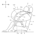
- FIG. 2 is a schematic view showing a state in which the airbag 3 is expanded and deployed in the occupant restraint device 100.
- FIG. 2 shows only the expansion and deployment of the airbag 3 on the left side of the occupant P seated on the seat cushion 8 for convenience.
- the airbag 3 expands and expands on both the left and right sides of the occupant P in the same manner, the position of the airbag 3 on the left side is adjusted by the tension cloth 2a, and the position of the airbag 3 on the right side is adjusted by the tension cloth 2b. It is done (see Figure 3).
- the operation and operation of the tension cloth 2a on the left side of the sheet 5 will be described with reference to FIG. 2, and the description of the tension cloth 2b on the right side will be omitted.
- the airbag 3 on the left side breaks the cover from the inside of the side surface 42 of the seat back 4 and expands and expands toward the front side of the seat 5. Further, at the same time as the expansion and deployment of the airbag 3, the tension cloth 2a also pops out and is placed on the center side of the seat back 4, that is, on the occupant P side sitting on the seat cushion 8 so as to surround the outside of the expanding and expanding airbag 3. It is protected by letting the occupant P receive and restrain it.
- the tension cloth 2a inevitably comes into partial contact with the outer surface of the airbag 3.
- the tension cloth 2a is sewn to the airbag 3 at a predetermined position in the contact portion between the airbag 3 and the tension cloth 2a to be connected.
- the tension cloth 2a is sewn to the airbag 3 at two joint portions 23a and 24a indicated by "X".
- the coupling portion 23a is located below the coupling portion 24a.
- a holding groove 9a for holding the tension cloth 2a is formed below the coupling portion 23a and below the airbag 3 as described later.
- the holding groove 9a receives and holds the tension cloth 2a when the airbag 3 expands and expands, and prevents the airbag 3 from coming off from the proper position.
- the lower part of the airbag 3 means from the lower end portion of the expanded and expanded airbag 3 to the portion of the airbag 3 that expands most in the vehicle width direction.
- the portion below the middle portion in the vertical direction of the airbag 3 is shown, but the present invention is not necessarily limited thereto.
- the upper part of the airbag 3 means from the upper end portion of the expanded and expanded airbag 3 to the portion that expands most in the vehicle width direction of the airbag 3. Generally, it indicates a portion above the middle portion in the vertical direction of the airbag 3, but is not necessarily limited thereto.
- the most swelling part of the airbag 3 in the vehicle width direction is the most swelling part in the contact area where the expanded and expanded airbag 3 comes into contact with the tension cloths 2a and 2b, and is the most swelling part in the entire airbag 3. It may be different from the bulging part.
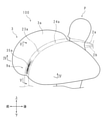
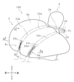
- FIG. 3 is an enlarged view of the expanded and expanded airbag 3
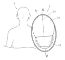
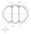
- FIG. 4 is a cross-sectional view of the airbag 3 by the IV-IV line of FIG.
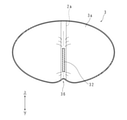
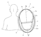
- FIG. 5 is a cross-sectional view of the airbag 3 by the V-V line of FIG. It is a vertical sectional view of the airbag 3.
- FIG. 4 is a view seen from below, and in FIG. 5, the occupant P is shown by a two-dot chain line for convenience of explanation. Further, in FIGS. 3 and 4, the tension cloth 2a is shown by a two-dot chain line for convenience.
- FIG. 6 is a vertical cross-sectional view of the airbag 3 along the VI-VI line of FIG.
- the tension cloth 2a is shown by a broken line for convenience.
- the airbag 3 is a bag body formed by joining a first panel 3a (contact portion) and a second panel 3b (non-contact portion) having substantially the same shape by stitching the peripheral edges.
- the first panel 3a and the second panel 3b are, for example, circular. Therefore, when the airbag 3 is expanded and expanded, the expansion is restricted by the seams 34, and when the expansion and expansion is completed, the airbag 3 has a substantially elliptical shape in the vertical cross-sectional view and the cross-sectional view.
- the first panel 3a and the second panel 3b face each other, the first panel 3a is connected to the tension cloth 2a as described above, and the second panel 3b is an occupant. Facing P.
- the seam 34 of the airbag 3 is shown by a alternate long and short dash line.
- the airbag 3 is provided with an internal tether 32 that regulates the shape of the airbag 3 during expansion and deployment. Further, in the lower part of the airbag 3, as will be described later, a holding groove 9a is formed in the first panel 3a, and a groove 9b is formed in the second panel 3b. The holding groove 9a and the groove 9b are formed by an internal tether 32.
- an internal tether 32 for convenience of explanation, a case where the airbag 3 is expanded and expanded will be described.
- the internal tether 32 is provided inside the airbag 3.
- the internal tether 32 has a substantially trapezoidal sheet shape, and is provided at the lower part of the airbag 3 with the short side facing down and the long side facing up among two substantially parallel sides (FIG. 5). reference).
- the internal tether 32 is provided at a predetermined distance from the lower end portion of the airbag 3.
- the internal tether 32 is erected between the first panel 3a and the second panel 3b. Of the two sides adjacent to the short side of the internal tether 32, one is sewn to the lower part of the first panel 3a and the other is sewn to the lower part of the second panel 3b. As a result, a seam 35a is formed on the first panel 3a, and a seam 35b is formed on the second panel 3b (see FIGS. 3 and 4).
- the airbag 3 is in the facing direction of the first panel 3a and the second panel 3b during expansion and deployment. Expansion in (hereinafter, in the thickness direction of the airbag 3) is limited.
- first panel 3a is coupled to the internal tether 32 at the lower seam 35a
- second panel 3b is coupled to the internal tether 32 at the lower seam 35b. Therefore, in the first panel 3a, the parts other than the part corresponding to the seam 35a can be expanded relatively freely, and in the second panel 3b, the parts other than the part corresponding to the seam 35b are relative. Can expand freely.
- the airbag 3 when the airbag 3 is expanded and expanded, the lower portion of the first panel 3a and the lower portion of the second panel 3b are pulled to each other via the internal tether 32. Therefore, in the first panel 3a, the portion related to the seam 35a and the seam 35a. In the second panel 3b, the portion related to the seam 35b and the periphery of the seam 35b are recessed. As a result, the holding groove 9a is formed in the first panel 3a, and the groove 9b is formed in the second panel 3b.
- the holding groove 9a is formed in the portion corresponding to the internal tether 32 (seam 35a). Further, also in the second panel 3b, a groove 9b is formed in a portion corresponding to the internal tether 32 (seam 35b) (see FIG. 4). In FIG. 5, the outside of the region surrounded by the broken line corresponds to the holding groove 9a and the groove 9b.
- the internal tether 32 is substantially trapezoidal and has predetermined dimensions in the height direction. Therefore, the seams 35a and the seams 35b are formed in the vertical direction over a predetermined range. Therefore, the holding groove 9a and the groove 9b extend in the vertical direction over a predetermined range. Further, since the internal tether 32 is substantially trapezoidal, the dimension in the direction intersecting the height direction (hereinafter referred to as the width direction) gradually decreases downward.
- the periphery of the seam 35a is recessed in the first panel 3a
- the periphery of the seam 35b is recessed in the second panel 3b
- the internal tether 32 is gradually sized downward in the width direction. is decreasing.
- the holding groove 9a of the first panel 3a and the groove 9b of the second panel 3b are connected to each other at the lower portion of the airbag 3, and a recess 36 is formed at the lower end portion of the airbag 3.
- a holding groove 9a is provided at the lower part of the first panel 3a that comes into contact with the tension cloth 2a so as to extend in the vertical direction. It is formed.
- the tension cloth 2a is received in the holding groove 9a (see FIG. 4).
- both ends in the width direction are in contact with the first panel 3a in the holding groove 9a, whereas there is a gap between the central portion excluding both ends and the first panel 3a. do.
- the tension cloth 2a can slide on the first panel 3a along the length direction of the holding groove 9a in the holding groove 9a (see FIG. 6). Further, the tension cloth 2a is restricted from moving in the width direction of the holding groove 9a. Therefore, at the time of expansion and deployment, the lower part of the airbag 3 can be prevented from being separated from the tension cloth 2a and deviating from the assumed position, and the tension cloth 2a surely urges the airbag 3 to the occupant P side to adjust the position. It can be performed.
- the position of the internal tether 32 is not limited to the position exemplified in FIGS. 4 to 6.
- An internal tether 32 is provided so that a holding groove 9a is formed at a position where the airbag 3 in which the tension cloth 2a expands and expands should be brought into contact with the airbag 3 so as to be properly brought toward the occupant P.
- the internal tether 32 has a substantially trapezoidal shape, and its dimension in the width direction gradually decreases downward.
- the lower end portion 22a of the tension cloth 2a is held by the lower fixing portion 81 provided on the center side of the front portion of the seat cushion 8 (see FIG. 1). That is, the closer the holding groove 9a is to the lower end portion of the airbag 3, the closer it is to the lower end portion 22a (lower fixing portion 81) of the tension cloth 2a. Therefore, when the airbag 3 is expanded and expanded, the tension cloth 2a is easily received by the holding groove 9a.
- the holding groove 9a is provided at the lower part of the airbag 3 and the recess 36 is formed at the lower end portion of the airbag 3, tension is applied to the holding groove 9a and the recess 36 when the airbag 3 expands and expands.
- the cloth 2a is fitted and the airbag 3 is lifted so as to be more accurately arranged at a desired position close to the head of the occupant P.
- the position adjustment of the expanding and expanding airbag 3 can be adjusted more stably.
- the tension cloth 2a has two connecting portions 23a and 24a has been described as an example, but the present invention is not limited to this.
- the connecting portions 23a and 24a are not essential and may be omitted.
- the joint portion may be one place or three or more places.
- the connecting portions 23a and 24a may be provided over a predetermined range along the longitudinal direction of the tension cloth 2a.
- the tension cloths 2a and 2b are sewn on the airbag 3 has been described as an example, but the present invention is not limited to this.
- the tension cloth 2a may be fixed to the airbag 3 with an adhesive, or may be fixed with a hook-and-loop fastener or the like.
- the tension cloths 2a and 2b may be a cloth having a wide width or a cloth having a large area.
- FIG. 7 is a schematic view showing a state in which the airbag 3 is expanded and expanded in the occupant restraint device 100 according to the second embodiment.
- FIG. 7 shows only the expansion and deployment of the airbag 3 on the left side of the occupant P for convenience, but in reality, the airbag 3 expands and expands on both the left and right sides of the occupant P in the same manner.
- the position of the left airbag 3 is adjusted by the tension cloths 2a and 2c, and the position of the right airbag 3 is adjusted by the tension cloths 2b and 2d. Is performed (see FIG. 8). In the following, only an example of expansion and deployment of the airbag 3 on the left side of the occupant P will be described with reference to FIG. 7.
- the upper end 21a of the tension cloth 2a and the upper end 21c of the tension cloth 2c are fixed to the upper part of the seat back 4. Further, the lower end portion 22a of the tension cloth 2a and the lower end portion 22c of the tension cloth 2c are held by the lower fixing portion 81 on the front center side of the seat cushion 8 (see FIG. 1). The tension cloths 2a and 2c are arranged together on the left side of the sheet 5.
- the tension cloth 2a has two connecting portions 23a and 24a
- the tension cloth 2c has two connecting portions 23c and 24c.
- the coupling portion 23a is located below the coupling portion 24a, and among the coupling portion 23c and the coupling portion 24c, the coupling portion 23c is located below the coupling portion 24c.
- a holding groove 9c is provided below the coupling portion 23a of the tension cloth 2a and below the airbag 3 to receive and hold the tension cloth 2a when the airbag 3 expands and expands.
- a holding groove 9d is provided below the coupling portion 23c of the tension cloth 2c and below the airbag 3 to receive and hold the tension cloth 2c when the airbag 3 expands and expands.
- the holding grooves 9c and 9d receive and hold the tension cloths 2a and 2c, respectively, when the airbag 3 expands and expands, and prevents the airbag 3 from deviating from the assumed position.
- FIG. 8 is an enlarged view of the expanded and expanded airbag 3
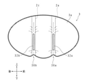
- FIG. 9 is a cross-sectional view of the airbag 3 by IX-IX line of FIG. 8
- FIG. 10 is a cross-sectional view of the airbag 3 by X-ray of FIG. It is a vertical sectional view of the airbag 3.
- FIG. 9 is a view seen from below, and in FIG. 10, the occupant P is shown by a two-dot chain line for convenience of explanation.
- 11 is a vertical sectional view of the airbag 3 taken along the line XI-XI of FIG. 10.
- FIG. For convenience, the tension cloths 2a and 2c are shown by a two-dot chain line in FIGS. 8 and 9, and are shown by a broken line in FIG.
- the airbag 3 is a bag body formed by joining a first panel 3a and a second panel 3b having substantially the same shape by stitching the peripheral edges.
- the first panel 3a and the second panel 3b are, for example, circular. Therefore, when the airbag 3 is expanded and expanded, the expansion is restricted by the seams 34, and when the expansion and expansion is completed, the airbag 3 has a substantially elliptical shape in the vertical cross-sectional view and the cross-sectional view.
- the first panel 3a and the second panel 3b face each other, the first panel 3a is coupled to the tension cloths 2a and 2c, and the second panel 3b faces the occupant P. ..
- the seam 34 of the airbag 3 is shown by a alternate long and short dash line.
- the airbag 3 is provided with internal tethers 32a and 32b, and holding grooves 9c and 9d are formed in the first panel 3a at the lower portion of the airbag 3 as described later, and the second panel 3b is formed. Grooves 9e and 9f are formed in the groove 9e and 9f. The holding grooves 9c, 9d and the grooves 9e, 9f are formed by the internal tethers 32a, 32b.
- the airbag 3 is expanded and expanded will be described.
- the internal tethers 32a and 32b are provided inside the airbag 3.
- the internal tethers 32a and 32b have a substantially trapezoidal sheet shape, and are provided at the lower part of the airbag 3 with the short side facing down and the long side facing up among the two substantially parallel sides (the short side is on the lower side and the long side is on the upper side). See FIG. 10).
- the internal tethers 32a and 32b are provided at predetermined intervals from the lower end portion of the airbag 3.
- the internal desserts 32a and 32b are provided at predetermined intervals in the front-rear direction.
- the internal tethers 32a and 32b are erected between the first panel 3a and the second panel 3b. Of the two sides of the internal tethers 32a and 32b adjacent to the short side, one is sewn to the lower part of the first panel 3a and the other is sewn to the lower part of the second panel 3b. Seams 35c and 35d are formed on the first panel 3a, and seams 35e and 35f are formed on the second panel 3b (see FIGS. 8 and 9).
- the airbag 3 is restricted from expanding in the thickness direction during expansion and deployment.
- first panel 3a is connected to the internal tethers 32a and 32b at the lower seams 35c and 35d
- the second panel 3b is connected to the internal tethers 32a and 32b at the lower seams 35e and 35f. Therefore, in the first panel 3a, the parts other than the parts corresponding to the seams 35c and 35d can be expanded relatively freely, and in the second panel 3b, the parts other than the parts corresponding to the seams 35e and 35f are excluded. The part can expand relatively freely.
- the airbag 3 when the airbag 3 is expanded and expanded, the lower part of the first panel 3a and the lower part of the second panel 3b are pulled to each other via the internal tethers 32a and 32b, so that the seams 35c and 35d are related to the first panel 3a.
- the portions and the periphery of the seams 35c and 35d are recessed, and in the second panel 3b, the portions related to the seams 35e and 35f and the periphery of the seams 35e and 35f are recessed.
- holding grooves 9c and 9d are formed in the first panel 3a, and grooves 9e and 9f are formed in the second panel 3b.
- holding grooves 9c and 9d are formed in the portions corresponding to the internal tethers 32a and 32b (seam 35c and 35d), respectively.
- grooves 9e and 9f are formed in the portions corresponding to the internal tethers 32a and 32b (seam 35e and 35f) (see FIG. 9).
- the outer sides of the regions A and C surrounded by the broken line correspond to the holding grooves 9c and 9d, respectively, and the outer sides of the regions B and D surrounded by the broken line correspond to the grooves 9e and 9f, respectively.
- the internal tethers 32a and 32b are substantially trapezoidal, the seams 35c and 35d and the seams 35e and 35f are formed in the vertical direction over a predetermined range. Therefore, the holding grooves 9c and 9d and the grooves 9e and 9f extend in the vertical direction over a predetermined range. Further, since the internal tethers 32a and 32b are substantially trapezoidal, the dimensions in the width direction gradually decrease downward.
- the periphery of the seams 35c and 35d is recessed in the first panel 3a
- the periphery of the seams 35e and 35f is recessed in the second panel 3b
- the internal tethers 32a and 32b have dimensions in the width direction. It is gradually decreasing downward.
- the holding grooves 9c and 9d of the first panel 3a and the grooves 9e and 9f of the second panel 3b are connected at the lower part of the airbag 3, and recesses 36a and 36b are formed at two places at the lower end of the airbag 3. Has been done.
- holding grooves 9c and 9d are formed on the first panel 3a so as to extend in the vertical direction when the airbag 3 is expanded and deployed.
- the tension cloths 2a and 2c are received in the holding grooves 9c and 9d (see FIG. 9).
- both ends in the width direction are in contact with the first panel 3a in the holding groove 9c, whereas there is a gap between the central portion excluding both ends and the first panel 3a. do.
- both ends in the width direction are in contact with the first panel 3a in the holding groove 9d, whereas there is a gap between the central portion excluding both ends and the first panel 3a. (See FIG. 9).
- the tension cloth 2a can slide on the first panel 3a along the length direction of the holding groove 9c in the holding groove 9c, and the tension cloth 2c is the first in the holding groove 9d. It is slidable on the panel 3a along the length direction of the holding groove 9d (see FIG. 11). Further, the tension cloth 2a is restricted from moving in the width direction of the holding groove 9c, and the tension cloth 2c is restricted from moving in the width direction of the holding groove 9d.
- the lower part of the airbag 3 can be prevented from being separated from the tension cloths 2a and 2c and deviating from the assumed position, and the tension cloths 2a and 2c surely urge the airbag 3 to the occupant P side.
- the position can be adjusted.
- the internal tethers 32a and 32b are provided so that the holding grooves 9c and 9d are formed at positions where the tension cloths 2a and 2c should be in contact with each other in order to properly bring the airbag 3 that expands and expands toward the occupant P.
- Each is provided.
- the internal tethers 32a and 32b are substantially trapezoidal, and their dimensions in the width direction gradually decrease downward. That is, the closer the holding grooves 9c and 9d are to the lower end of the airbag 3, the closer to the lower end 22a of the tension cloth 2a and the lower end 22c of the tension cloth 2c, that is, the lower fixing portion 81. Therefore, when the airbag 3 is expanded and expanded, the tension cloths 2a and 2c are easily received by the holding grooves 9c and 9d.
- the holding grooves 9c and 9d are provided in the lower portion of the airbag 3 and the recesses 36a and 36b are formed in the lower end portion of the airbag 3, the holding grooves 9c and the holding grooves 9c and 9d are formed when the airbag 3 expands and expands.
- the tension cloth 2a is fitted into the recess 36a, the tension cloth 2c is fitted into the holding groove 9d and the recess 36b, and the airbag 3 is lifted to be appropriately arranged at a desired position close to the head of the occupant P.
- the airbag 3 and the tension cloth 2a are previously bonded at the connecting portions 23a and 24a, and the airbag 3 and the tension cloth 2c are previously bonded at the connecting portions 23c and 24c.
- the position adjustment of the expanding and expanding airbag 3 can be adjusted more stably.
- the two tension cloths 2a and 2c adjust the positions with respect to one airbag 3, and the airbags 3 and the two tension cloths 2a and 2c are connected to the joint portions 23a, 24a and 23c.
- the position adjustment of the expanding and expanding airbag 3 can be adjusted more stably.
- FIG. 12 is a schematic view showing a state in which the airbag 3 is expanded and expanded in the occupant restraint device 100 according to the third embodiment.
- FIG. 12 shows only the expansion and deployment of the airbag 3 on the left side of the occupant P.
- the airbag 3 expands and expands on both the left and right sides of the occupant P in the same manner. Therefore, in the following, only an example of the expansion and expansion of the airbag 3 on the left side of the occupant P will be described with reference to FIG.
- the tension cloth 2a and the tension cloth 2c are provided for one airbag 3 on the left side.
- the upper end portion 21a of the tension cloth 2a and the upper end portion 21c of the tension cloth 2c are fixed to the fixed position F1 (see FIG. 1) of the seat back 4.
- the lower end portion 22a of the tension cloth 2a and the lower end portion 22c of the tension cloth 2c are held by the lower fixing portion 81 (see FIG. 1) on the front center side of the seat cushion 8.
- the tension cloths 2a and 2c are arranged together on the left side of the sheet 5.
- the tension cloth 2a has two joint portions 23a and 24a, and the joint portion 23a is located below the joint portion 24a. Further, the tension cloth 2c has two joint portions 23c and 24c, and the joint portion 23c is located below the joint portion 24c.
- the upper portion of the tension cloth 2a and the tension cloth 2c is integrated. That is, the upper end portion 21a of the tension cloth 2a and the upper end portion 21c of the tension cloth 2c are sewn together, for example, over a predetermined range to form the integrated portion 2e.
- the integrated portion 2e is formed between the joint portion 24a of the tension cloth 2a and the joint portion 24c of the tension cloth 2c, and the fixed position F1 on the upper part of the seat back 4. Further, the integrated portion 2e may be formed by using an adhesive.
- a holding groove 9c which is below the joint portion 23a of the tension cloth 2a and receives and holds the tension cloth 2a is provided in the lower part of the airbag 3. It is provided.
- a holding groove 9d that receives and holds the tension cloth 2c is provided in the lower part of the airbag 3 below the joint portion 23c of the tension cloth 2c. The holding grooves 9c and 9d restrain the airbag 3 to the tension cloths 2a and 2c so that the airbag 3 does not separate from the assumed position when the airbag 3 expands and expands.
- the holding grooves 9c and 9d are formed in the airbag 3 and the tension cloths 2a and 2c are held in the holding grooves 9c and 9d at the time of expansion and deployment.
- the airbag 3 is restrained by the tension cloths 2a and 2c. Therefore, it is possible to prevent the lower portion of the airbag 3 from being separated from the tension cloths 2a and 2c and deviating from the assumed position. Therefore, the tension cloths 2a and 2c can surely bring the airbag 3 closer to the occupant P side and arrange it.
- holding grooves 9c and 9d are formed at positions where the tension cloths 2a and 2c should be in contact with each other in order to properly bring the airbag 3 inflated and expanded toward the occupant P. Therefore, when the airbag 3 expands and expands, the tension cloths 2a and 2c are easily received by the holding grooves 9c and 9d.
- the upper end portion 21a of the tension cloth 2a and the upper end portion 21c of the tension cloth 2c are sewn over a predetermined range to form the integrated portion 2e. ing.
- the work of arranging the tension cloth 2a and the tension cloth 2c on the side portion of the seat back 4 becomes easy. Further, when the airbag 3 expands and expands, the upper end portion 21a of the tension cloth 2a and the upper end portion 21c of the tension cloth 2c both pop out, so that the position of the airbag 3 can be adjusted earlier.
- FIG. 13 is a schematic view showing a state in which the airbag 3 is expanded and expanded in the occupant restraint device 100 according to the fourth embodiment.
- FIG. 13 shows only the expansion and deployment of the airbag 3 on the left side of the occupant P for convenience.
- the airbag 3 expands and expands on both the left and right sides of the occupant P in the same manner. Therefore, in the following, only an example of the expansion and expansion of the airbag 3 on the left side of the occupant P will be described with reference to FIG.
- the tension cloth 2a and the tension cloth 2c are provided for one airbag 3 on the left side.
- the upper end portion 21a of the tension cloth 2a and the upper end portion 21c of the tension cloth 2c are fixed to the upper part of the seat back 4.
- the lower end portion 22a of the tension cloth 2a and the lower end portion 22c of the tension cloth 2c are held by the lower fixing portions 81 (see FIG. 1) of the seat cushion 8 via the pretensioner mechanisms 25a and 25b (tension applying mechanism), respectively. ing.
- the pretensioner mechanisms 25a and 25b apply tension to the tension cloths 2a and 2c, respectively.
- the pretensioner mechanism 25a is provided between the lower end portion 22a of the tension cloth 2a and the lower fixing portion 81 of the seat cushion 8, and the pretensioner mechanism 25b is provided on the lower end portion 22c of the tension cloth 2c and the lower side of the seat cushion 8. It is provided between the fixed portion 81 and the fixed portion 81.
- the pretensioner mechanisms 25a and 25b have the same configuration as the buckle pretensioner used for pulling in the buckle of the vehicle seat belt in response to an impact.
- the pretensioner mechanisms 25a and 25b apply tension by pulling the tension cloths 2a and 2c toward the lower fixing portion 81 when the airbag 3 expands and expands.
- the tension cloth 2a has two connecting portions 23a and 24a
- the tension cloth 2c has two connecting portions 23c and 24c.
- the tension cloths 2a and 2c are received and held under the airbag 3 respectively.
- Grooves 9c and 9d are formed.
- a holding groove 9c for holding the tension cloth 2a is formed below the joint portion 23a of the tension cloth 2a
- a holding groove 9d for holding the tension cloth 2c is formed below the joint portion 23c of the tension cloth 2c. ..
- the lower portion of the airbag 3 can be prevented from being separated from the tension cloths 2a and 2c and deviating from the assumed position, and the tension cloths 2a and 2c can be prevented from deviating from the assumed position.
- the airbag 3 can be appropriately placed close to the occupant P side.
- the tension cloths 2a and 25b pull the tension cloths 2a and 2c toward the lower fixing portion 81 when the airbag 3 is expanded and deployed. 2c can strengthen the force to urge the airbag 3 to the occupant P side. Therefore, the airbag 3 can be more quickly and surely arranged on the occupant P side to protect the occupant P.
- FIG. 14 is a schematic view showing a state in which the airbag 3 is expanded and expanded in the occupant restraint device 100 according to the fifth embodiment.
- FIG. 14 shows only the expansion and deployment of the airbag 3 on the left side of the occupant P for convenience.
- the airbag 3 expands and expands on both the left and right sides of the occupant P in the same manner. Therefore, in the following, only an example of the expansion and expansion of the airbag 3 on the left side of the occupant P will be described with reference to FIG.
- FIG. 14 for convenience, only the seat cushion 8 is shown in a vertical cross-sectional view.
- the tension cloth 2a and the tension cloth 2c are provided for one airbag 3 on the left side.
- the upper end portion 21a of the tension cloth 2a and the upper end portion 21c of the tension cloth 2c are fixed to the upper part of the seat back 4. Further, the lower end portion 22a of the tension cloth 2a and the lower end portion 22c of the tension cloth 2c are held by the lower fixing portion 81 (see FIG. 1) of the seat cushion 8.
- the tension cloth 2a has two connecting portions 23a and 24a
- the tension cloth 2c has two connecting portions 23c and 24c.
- the tension cloths 2a and 2c are received and held under the airbag 3 respectively.
- Grooves 9c and 9d are formed.
- the holding groove 9c is formed below the connecting portion 23a of the tension cloth 2a
- the holding groove 9d is formed below the connecting portion 23c of the tension cloth 2c. Since the configurations of the holding grooves 9c and 9d are the same as those in the second embodiment, detailed description thereof will be omitted.
- the seat cushion 8 includes a cushion pad 82 and a panel member 86 arranged under the cushion pad 82 and supporting the cushion pad 82.
- the cushion pad 82 is made of a cushioning material that absorbs impact, and the panel member 86 constitutes the bottom of the seat cushion 8.
- the seat cushion 8 is provided with an airbag device 83 (tension applying mechanism) inside.
- the airbag device 83 is interposed between the cushion pad 82 and the panel member 86.
- the airbag device 83 includes, for example, an airbag 85, which is a bag formed by sewing the peripheral edges of two panels together, and an inflator 84, which ejects gas into the airbag 85.
- the airbag 85 Before expansion and deployment, the airbag 85 is laid flat on the panel member 86 at a position corresponding to the thigh to the buttocks of the occupant P.
- the inflator 84 operates to supply gas into the airbag 85, and the airbag 85 expands and expands upward.
- the lower part of the airbag 3 can be prevented from being separated from the tension cloths 2a and 2c and deviating from the assumed position, and the tension cloths 2a and 2c can be prevented from departing.
- the airbag 3 can be appropriately placed close to the occupant P side.
- the airbag device 83 is provided inside the seat cushion 8, and when a vehicle collision occurs, the airbag 85 is transferred from the panel member 86 to the cushion pad 82. It expands and expands toward. At this time, the airbag 85 pushes up the portion from the thigh to the buttocks of the occupant P via the cushion pad 82. As a result, the load applied to the tension cloth 2a and the tension cloth 2c increases, and tension is applied to the tension cloth 2a and the tension cloth 2c.
- the airbag 3 can be more reliably arranged on the occupant P side to receive and protect the occupant P.
- Airbag module 2a, 2b, 2c, 2d Tension cloth 2e Integrated part 3 Airbag 3a 1st panel 3b 2nd panel 4 Seat back 5 Seat 7 Headrest part 8 Seat cushion 9a, 9c, 9d Holding groove 23a, 24a, 23c, 24c Coupling part 25a, 25b
Landscapes
- Engineering & Computer Science (AREA)
- Mechanical Engineering (AREA)
- Air Bags (AREA)
Abstract
Description
本出願は、2020年7月28日出願の日本出願第2020-127516号に基づく優先権を主張し、前記日本出願に記載された全ての記載内容を援用するものである。
これに対しては、張力布を用いて、膨張展開するエアバッグの位置を調整する技術が知られている。斯かる技術においては、エアバッグが膨張展開する際、張力布がエアバッグの外側を囲んで保持して乗員側に寄せ付ける。
しかしながら、上述したような特許文献1に係る技術では、このような問題を解決できない。
本発明の実施の形態に係る乗員拘束装置は、車両のシートに装着される。
図1は、実施の形態1に係る乗員拘束装置100が車両のシート5に取り付けられた状態を示す図である。図1においては、エアバッグが膨張展開する前の状態が示されている。以下においては、便宜上、図にて定義する前後、左右、上下の各方向を用いて説明を行う。
エアバッグモジュール1aはシートバック4の左側部に設けられ、エアバッグモジュール1bはシートバック4の右側部に設けられている。シートバック4の内部のフレーム(図示せず)と該フレームを覆うカバーとの間にエアバッグモジュール1a,1bが配置されている。
以下においては、図2を用いて、シート5の左側の張力布2aの作用、動作を説明し、右側の張力布2bについては説明を省略する。
以下では、説明の便宜上、エアバッグ3が膨張展開した場合を用いて説明する。
よって、膨張展開の際、エアバッグ3の下部が張力布2aから離れ、想定の位置から逸脱することを抑制でき、張力布2aが確実にエアバッグ3を乗員P側に付勢して位置調整を行うことができる。
即ち、保持溝9aは、エアバッグ3の下端部に近い程、張力布2aの下端部22a(下側固定部81)に近接している。よって、エアバッグ3の膨張展開の際、張力布2aが保持溝9aに受容されやすい。
実施の形態1においては、各エアバッグ3に対して張力布2a,2bが一本ずつ設けられた場合を例に挙げて説明したが、これに限定されるものではない。
以下においては、図7を用いて乗員Pの左側におけるエアバッグ3の膨張展開の例のみを説明する。
以下では、説明の便宜上、エアバッグ3が膨張展開した場合を用いて説明する。
また、張力布2aは保持溝9cの幅方向への移動が制限され、張力布2cは保持溝9dの幅方向への移動が制限される。
図12は、実施の形態3に係る乗員拘束装置100においてエアバッグ3が膨張展開した状態を示す模式図である。図12では、乗員Pの左側におけるエアバッグ3の膨張展開の様子のみを示している。実際は、乗員Pの左右両側において同様にエアバッグ3が膨張展開するので、以下においては、図12を用いて乗員Pの左側におけるエアバッグ3の膨張展開の例のみを説明する。
図13は、実施の形態4に係る乗員拘束装置100においてエアバッグ3が膨張展開した状態を示す模式図である。図13では、便宜上、乗員Pの左側におけるエアバッグ3の膨張展開の様子のみを示している。実際は、乗員Pの左右両側において同様にエアバッグ3が膨張展開するので、以下においては、図13を用いて乗員Pの左側におけるエアバッグ3の膨張展開の例のみを説明する。
また、実施の形態2と同様に、実施の形態4の乗員拘束装置100では、エアバッグ3の膨張展開の際、エアバッグ3の下部に、張力布2a,2cを夫々受容して保持する保持溝9c,9dが形成される。張力布2aの結合部23aよりも下方に、張力布2aを保持する保持溝9cが形成され、張力布2cの結合部23cよりも下方に、張力布2cを保持する保持溝9dが形成される。
図14は、実施の形態5に係る乗員拘束装置100においてエアバッグ3が膨張展開した状態を示す模式図である。図14では、便宜上、乗員Pの左側におけるエアバッグ3の膨張展開の様子のみを示している。実際は、乗員Pの左右両側において同様にエアバッグ3が膨張展開するので、以下においては、図14を用いて乗員Pの左側におけるエアバッグ3の膨張展開の例のみを説明する。
なお、図14においては、便宜上、シートクッション8のみを縦断面視にて示す。
また、張力布2aの下端部22a及び張力布2cの下端部22cはシートクッション8の下側固定部81(図1参照)に保持されている。
また、実施の形態2と同様に、実施の形態5の乗員拘束装置100では、エアバッグ3の膨張展開の際、エアバッグ3の下部に、張力布2a,2cを夫々受容して保持する保持溝9c,9dが形成される。張力布2aの結合部23aよりも下方に、保持溝9cが形成され、張力布2cの結合部23cよりも下方に、保持溝9dが形成される。
保持溝9c,9dの構成については、実施の形態2と同様であるので、詳しい説明を省略する。
なお、請求の範囲には、理解を助けるために参照符号を付している。本発明の範囲は、斯かる参照符号によって特定される明細書の記載に限定されず、請求の範囲によって示され、請求の範囲と均等の意味及び範囲内でのすべての変更を含む。
2a,2b,2c,2d 張力布
2e 一体化部
3 エアバッグ
3a 第1パネル
3b 第2パネル
4 シートバック
5 シート
7 ヘッドレスト部
8 シートクッション
9a,9c,9d 保持溝
23a,24a,23c,24c 結合部
25a,25b プリテンショナ機構
32,32a,32b 内部テザー
36,36a,36b 凹部
41 上面
42,43 側面
83 エアバッグ装置
100 乗員拘束装置
F1,F2 固定位置
P 乗員
Claims (10)
- 両端が車両用シート(5)の上部及び下部に夫々固定され、前記シート(5)に着座する乗員(P)の側部で膨張展開するエアバッグ(3)を前記乗員(P)に向けて寄せ付ける張力布(2a,2b,2c,2d)を備える乗員拘束装置(100)において、
前記エアバッグ(3)には、膨張展開の際に、前記張力布(2a,2b,2c,2d)を保持する保持溝(9a,9c,9d)が形成されることを特徴とする乗員拘束装置(100)。 - 前記張力布(2a,2b,2c,2d)は、前記エアバッグ(3)の表面に少なくとも一箇所の結合部(23a,24a,23c,24c)で結合されていることを特徴とする請求項1に記載の乗員拘束装置(100)。
- 前記保持溝(9a,9c,9d)は前記エアバッグ(3)の下部に形成されることを特徴とする請求項1または2に記載の乗員拘束装置(100)。
- 前記保持溝(9a,9c,9d)は、膨張展開したエアバッグ(3)の上下方向に延びることを特徴とする請求項1から3の何れか一項に記載の乗員拘束装置(100)。
- 前記張力布(2a,2b,2c,2d)は、
前記エアバッグ(3)の膨張展開の際、前記保持溝(9a,9c,9d)内に受容され、
前記保持溝(9a,9c,9d)の長さ方向に沿って摺動可能であり、
前記保持溝(9a,9c,9d)は、
前記張力布(2a,2b,2c,2d)が前記保持溝(9a,9c,9d)の幅方向への移動することを制限することを特徴とする請求項1から4の何れか一項に記載の乗員拘束装置(100)。 - 膨張展開したエアバッグ(3)の下端部に、前記保持溝(9a,9c,9d)と連続する凹部(36,36a,36b)が形成されることを特徴とする請求項1から5の何れか一項に記載の乗員拘束装置(100)。
- 前記エアバッグ(3)は、
膨張展開の際に、前記張力布(2a,2b,2c,2d)と接触する接触部(3a)及び該接触部(3a)と対向する非接触部(3b)と、
前記接触部(3a)及び前記非接触部(3b)の間に架設され、前記エアバッグ(3)の形状を規制する内部テザー(32,32a,32b)とを備えており、
前記保持溝(9a,9c,9d)は、前記接触部(3a)において前記内部テザー(32,32a,32b)に対応する位置に形成されていることを特徴とする請求項1から6の何れか一項に記載の乗員拘束装置(100)。 - 前記張力布(2a,2b,2c,2d)が膨張展開する前記エアバッグ(3)を前記乗員(P)に向けて寄せ付けるために接触すべき位置に、前記保持溝(9a,9c,9d)が設けられていることを特徴とする請求項1から7の何れか一項に記載の乗員拘束装置(100)。
- 前記内部テザー(32,32a,32b)は、シート形状であり、下方に向かって縮幅していることを特徴とする請求項7に記載の乗員拘束装置(100)。
- 前記シート(5)に設けられ、前記張力布(2a,2b,2c,2d)に張力を付与する張力付与機構(25a,25b,83)を備えることを特徴とする請求項1から9のいずれか1項に記載の乗員拘束装置(100)。
Priority Applications (4)
| Application Number | Priority Date | Filing Date | Title |
|---|---|---|---|
| CN202180047925.XA CN115768662B (zh) | 2020-07-28 | 2021-06-25 | 乘员约束装置 |
| KR1020237006056A KR20230042329A (ko) | 2020-07-28 | 2021-06-25 | 승차인 구속 장치 |
| EP21850649.1A EP4190647A4 (en) | 2020-07-28 | 2021-06-25 | OCCUPANT RESTRAINT DEVICE |
| JP2022540078A JP7415011B2 (ja) | 2020-07-28 | 2021-06-25 | 乗員拘束装置 |
Applications Claiming Priority (2)
| Application Number | Priority Date | Filing Date | Title |
|---|---|---|---|
| JP2020127516 | 2020-07-28 | ||
| JP2020-127516 | 2020-07-28 |
Publications (1)
| Publication Number | Publication Date |
|---|---|
| WO2022024620A1 true WO2022024620A1 (ja) | 2022-02-03 |
Family
ID=80035522
Family Applications (1)
| Application Number | Title | Priority Date | Filing Date |
|---|---|---|---|
| PCT/JP2021/024059 Ceased WO2022024620A1 (ja) | 2020-07-28 | 2021-06-25 | 乗員拘束装置 |
Country Status (5)
| Country | Link |
|---|---|
| EP (1) | EP4190647A4 (ja) |
| JP (1) | JP7415011B2 (ja) |
| KR (1) | KR20230042329A (ja) |
| CN (1) | CN115768662B (ja) |
| WO (1) | WO2022024620A1 (ja) |
Cited By (3)
| Publication number | Priority date | Publication date | Assignee | Title |
|---|---|---|---|---|
| WO2022215543A1 (ja) * | 2021-04-09 | 2022-10-13 | オートリブ ディベロップメント エービー | 乗員拘束装置および乗員拘束装置の製造方法 |
| JP2024131794A (ja) * | 2023-03-16 | 2024-09-30 | トヨタ自動車株式会社 | 車両用乗員拘束装置 |
| JP2025509844A (ja) * | 2022-03-23 | 2025-04-11 | オートリブ ディベロップメント エービー | 車両シート |
Families Citing this family (3)
| Publication number | Priority date | Publication date | Assignee | Title |
|---|---|---|---|---|
| JP7816200B2 (ja) * | 2023-01-31 | 2026-02-18 | トヨタ自動車株式会社 | 車両用乗員拘束装置 |
| JP2025136153A (ja) * | 2024-03-06 | 2025-09-19 | トヨタ自動車株式会社 | 車両用乗員拘束装置 |
| JP2025136154A (ja) * | 2024-03-06 | 2025-09-19 | トヨタ自動車株式会社 | 車両用乗員拘束装置 |
Citations (6)
| Publication number | Priority date | Publication date | Assignee | Title |
|---|---|---|---|---|
| JP2006088714A (ja) * | 2004-09-21 | 2006-04-06 | Mazda Motor Corp | バックドアと後突用エアバッグ装置とを備えた車両 |
| JP2014012495A (ja) * | 2012-07-05 | 2014-01-23 | Autoliv Development Ab | サイドエアバッグ装置 |
| JP2014034356A (ja) | 2012-08-10 | 2014-02-24 | Toyota Motor Corp | 乗員保護装置 |
| JP2019051859A (ja) * | 2017-09-15 | 2019-04-04 | Joyson Safety Systems Japan株式会社 | エアバッグ及びシートベルト装置 |
| WO2020017282A1 (ja) * | 2018-07-19 | 2020-01-23 | オートリブ ディベロップメント エービー | 乗員拘束装置 |
| JP2020127516A (ja) | 2019-02-07 | 2020-08-27 | 京楽産業.株式会社 | 遊技機 |
Family Cites Families (8)
| Publication number | Priority date | Publication date | Assignee | Title |
|---|---|---|---|---|
| DE19641670A1 (de) * | 1996-10-10 | 1998-04-23 | Pars Passive Rueckhaltesysteme | Passives Rückhaltesystem für ein Kraftfahrzeug |
| US6029993A (en) * | 1997-10-06 | 2000-02-29 | Inova Gmbh Technische Entwicklungen | Side airbag device, method for operation thereof and vehicle seat therewith |
| JP2002362295A (ja) * | 2001-06-11 | 2002-12-18 | Toyoda Gosei Co Ltd | 頭部保護エアバッグ装置 |
| JP4835316B2 (ja) * | 2006-08-09 | 2011-12-14 | タカタ株式会社 | エアバッグ及びエアバッグ装置 |
| JP2016002822A (ja) * | 2014-06-14 | 2016-01-12 | タカタ株式会社 | 乗員拘束装置 |
| US9944245B2 (en) * | 2015-03-28 | 2018-04-17 | Amsafe, Inc. | Extending pass-through airbag occupant restraint systems, and associated systems and methods |
| KR102556814B1 (ko) * | 2018-07-19 | 2023-07-18 | 아우토리브 디벨롭먼트 아베 | 승차인 구속 장치 |
| JP6873961B2 (ja) * | 2018-10-16 | 2021-05-19 | オートリブ ディベロップメント エービー | 乗員拘束装置 |
-
2021
- 2021-06-25 KR KR1020237006056A patent/KR20230042329A/ko active Pending
- 2021-06-25 EP EP21850649.1A patent/EP4190647A4/en active Pending
- 2021-06-25 WO PCT/JP2021/024059 patent/WO2022024620A1/ja not_active Ceased
- 2021-06-25 CN CN202180047925.XA patent/CN115768662B/zh active Active
- 2021-06-25 JP JP2022540078A patent/JP7415011B2/ja active Active
Patent Citations (6)
| Publication number | Priority date | Publication date | Assignee | Title |
|---|---|---|---|---|
| JP2006088714A (ja) * | 2004-09-21 | 2006-04-06 | Mazda Motor Corp | バックドアと後突用エアバッグ装置とを備えた車両 |
| JP2014012495A (ja) * | 2012-07-05 | 2014-01-23 | Autoliv Development Ab | サイドエアバッグ装置 |
| JP2014034356A (ja) | 2012-08-10 | 2014-02-24 | Toyota Motor Corp | 乗員保護装置 |
| JP2019051859A (ja) * | 2017-09-15 | 2019-04-04 | Joyson Safety Systems Japan株式会社 | エアバッグ及びシートベルト装置 |
| WO2020017282A1 (ja) * | 2018-07-19 | 2020-01-23 | オートリブ ディベロップメント エービー | 乗員拘束装置 |
| JP2020127516A (ja) | 2019-02-07 | 2020-08-27 | 京楽産業.株式会社 | 遊技機 |
Non-Patent Citations (1)
| Title |
|---|
| See also references of EP4190647A4 |
Cited By (4)
| Publication number | Priority date | Publication date | Assignee | Title |
|---|---|---|---|---|
| WO2022215543A1 (ja) * | 2021-04-09 | 2022-10-13 | オートリブ ディベロップメント エービー | 乗員拘束装置および乗員拘束装置の製造方法 |
| JP2025509844A (ja) * | 2022-03-23 | 2025-04-11 | オートリブ ディベロップメント エービー | 車両シート |
| JP2024131794A (ja) * | 2023-03-16 | 2024-09-30 | トヨタ自動車株式会社 | 車両用乗員拘束装置 |
| JP7831364B2 (ja) | 2023-03-16 | 2026-03-17 | トヨタ自動車株式会社 | 車両用乗員拘束装置 |
Also Published As
| Publication number | Publication date |
|---|---|
| EP4190647A4 (en) | 2024-08-28 |
| CN115768662A (zh) | 2023-03-07 |
| CN115768662B (zh) | 2025-04-22 |
| JPWO2022024620A1 (ja) | 2022-02-03 |
| KR20230042329A (ko) | 2023-03-28 |
| EP4190647A1 (en) | 2023-06-07 |
| JP7415011B2 (ja) | 2024-01-16 |
Similar Documents
| Publication | Publication Date | Title |
|---|---|---|
| JP7415011B2 (ja) | 乗員拘束装置 | |
| JP6783715B2 (ja) | エアバッグ装置 | |
| JP7243552B2 (ja) | ファーサイドエアバッグ装置 | |
| KR102064844B1 (ko) | 자동차의 에어백 장치 | |
| KR102362655B1 (ko) | 사이드 에어백 장치 | |
| JP6327110B2 (ja) | 側突用エアバッグ装置 | |
| JP5724909B2 (ja) | サイドエアバッグ装置 | |
| US7407185B2 (en) | Passenger airbag with a diffuser | |
| JP7366251B2 (ja) | 乗員拘束装置 | |
| US11267432B2 (en) | Airbag | |
| KR20170036014A (ko) | 승차인 구속 장치 | |
| JP7205500B2 (ja) | ファーサイドエアバッグ装置 | |
| KR20200092449A (ko) | 자동차의 에어백 장치 | |
| US20180297549A1 (en) | Side airbag device | |
| KR102742412B1 (ko) | 승차인 구속 장치 | |
| JP2007230395A (ja) | エアバッグ及びエアバッグ装置 | |
| JP2020121601A (ja) | エアバッグシステム | |
| CN112141038A (zh) | 侧面安全气囊装置和膝部安全气囊装置 | |
| KR102167457B1 (ko) | 자동차의 에어백 장치 | |
| JP2022145179A (ja) | 車両用エアバッグ装置 | |
| KR102096933B1 (ko) | 자동차의 에어백 장치 | |
| CN116101215A (zh) | 气囊装置 | |
| WO2022215543A1 (ja) | 乗員拘束装置および乗員拘束装置の製造方法 | |
| JP2007099169A (ja) | エアバッグ装置 | |
| JP5983192B2 (ja) | サイドエアバッグ装置 |
Legal Events
| Date | Code | Title | Description |
|---|---|---|---|
| 121 | Ep: the epo has been informed by wipo that ep was designated in this application |
Ref document number: 21850649 Country of ref document: EP Kind code of ref document: A1 |
|
| ENP | Entry into the national phase |
Ref document number: 2022540078 Country of ref document: JP Kind code of ref document: A |
|
| ENP | Entry into the national phase |
Ref document number: 20237006056 Country of ref document: KR Kind code of ref document: A |
|
| WWE | Wipo information: entry into national phase |
Ref document number: 2021850649 Country of ref document: EP |
|
| ENP | Entry into the national phase |
Ref document number: 2021850649 Country of ref document: EP Effective date: 20230228 |
|
| NENP | Non-entry into the national phase |
Ref country code: DE |
|
| WWG | Wipo information: grant in national office |
Ref document number: 202180047925.X Country of ref document: CN |