WO2022024712A1 - 非水電解質二次電池 - Google Patents
非水電解質二次電池 Download PDFInfo
- Publication number
- WO2022024712A1 WO2022024712A1 PCT/JP2021/025880 JP2021025880W WO2022024712A1 WO 2022024712 A1 WO2022024712 A1 WO 2022024712A1 JP 2021025880 W JP2021025880 W JP 2021025880W WO 2022024712 A1 WO2022024712 A1 WO 2022024712A1
- Authority
- WO
- WIPO (PCT)
- Prior art keywords
- negative electrode
- active material
- electrode active
- positive electrode
- winding
- Prior art date
- Legal status (The legal status is an assumption and is not a legal conclusion. Google has not performed a legal analysis and makes no representation as to the accuracy of the status listed.)
- Ceased
Links
Images


Classifications
-
- H—ELECTRICITY
- H01—ELECTRIC ELEMENTS
- H01M—PROCESSES OR MEANS, e.g. BATTERIES, FOR THE DIRECT CONVERSION OF CHEMICAL ENERGY INTO ELECTRICAL ENERGY
- H01M4/00—Electrodes
- H01M4/02—Electrodes composed of, or comprising, active material
- H01M4/04—Processes of manufacture in general
- H01M4/0402—Methods of deposition of the material
- H01M4/0404—Methods of deposition of the material by coating on electrode collectors
-
- H—ELECTRICITY
- H01—ELECTRIC ELEMENTS
- H01M—PROCESSES OR MEANS, e.g. BATTERIES, FOR THE DIRECT CONVERSION OF CHEMICAL ENERGY INTO ELECTRICAL ENERGY
- H01M50/00—Constructional details or processes of manufacture of the non-active parts of electrochemical cells other than fuel cells, e.g. hybrid cells
- H01M50/50—Current conducting connections for cells or batteries
- H01M50/531—Electrode connections inside a battery casing
- H01M50/538—Connection of several leads or tabs of wound or folded electrode stacks
-
- H—ELECTRICITY
- H01—ELECTRIC ELEMENTS
- H01M—PROCESSES OR MEANS, e.g. BATTERIES, FOR THE DIRECT CONVERSION OF CHEMICAL ENERGY INTO ELECTRICAL ENERGY
- H01M10/00—Secondary cells; Manufacture thereof
- H01M10/05—Accumulators with non-aqueous electrolyte
- H01M10/052—Li-accumulators
-
- H—ELECTRICITY
- H01—ELECTRIC ELEMENTS
- H01M—PROCESSES OR MEANS, e.g. BATTERIES, FOR THE DIRECT CONVERSION OF CHEMICAL ENERGY INTO ELECTRICAL ENERGY
- H01M10/00—Secondary cells; Manufacture thereof
- H01M10/05—Accumulators with non-aqueous electrolyte
- H01M10/052—Li-accumulators
- H01M10/0525—Rocking-chair batteries, i.e. batteries with lithium insertion or intercalation in both electrodes; Lithium-ion batteries
-
- H—ELECTRICITY
- H01—ELECTRIC ELEMENTS
- H01M—PROCESSES OR MEANS, e.g. BATTERIES, FOR THE DIRECT CONVERSION OF CHEMICAL ENERGY INTO ELECTRICAL ENERGY
- H01M10/00—Secondary cells; Manufacture thereof
- H01M10/05—Accumulators with non-aqueous electrolyte
- H01M10/058—Construction or manufacture
- H01M10/0587—Construction or manufacture of accumulators having only wound construction elements, i.e. wound positive electrodes, wound negative electrodes and wound separators
-
- H—ELECTRICITY
- H01—ELECTRIC ELEMENTS
- H01M—PROCESSES OR MEANS, e.g. BATTERIES, FOR THE DIRECT CONVERSION OF CHEMICAL ENERGY INTO ELECTRICAL ENERGY
- H01M10/00—Secondary cells; Manufacture thereof
- H01M10/42—Methods or arrangements for servicing or maintenance of secondary cells or secondary half-cells
- H01M10/4235—Safety or regulating additives or arrangements in electrodes, separators or electrolyte
-
- H—ELECTRICITY
- H01—ELECTRIC ELEMENTS
- H01M—PROCESSES OR MEANS, e.g. BATTERIES, FOR THE DIRECT CONVERSION OF CHEMICAL ENERGY INTO ELECTRICAL ENERGY
- H01M4/00—Electrodes
- H01M4/02—Electrodes composed of, or comprising, active material
- H01M4/13—Electrodes for accumulators with non-aqueous electrolyte, e.g. for lithium-accumulators; Processes of manufacture thereof
- H01M4/133—Electrodes based on carbonaceous material, e.g. graphite-intercalation compounds or CFx
-
- H—ELECTRICITY
- H01—ELECTRIC ELEMENTS
- H01M—PROCESSES OR MEANS, e.g. BATTERIES, FOR THE DIRECT CONVERSION OF CHEMICAL ENERGY INTO ELECTRICAL ENERGY
- H01M4/00—Electrodes
- H01M4/02—Electrodes composed of, or comprising, active material
- H01M4/13—Electrodes for accumulators with non-aqueous electrolyte, e.g. for lithium-accumulators; Processes of manufacture thereof
- H01M4/134—Electrodes based on metals, Si or alloys
-
- H—ELECTRICITY
- H01—ELECTRIC ELEMENTS
- H01M—PROCESSES OR MEANS, e.g. BATTERIES, FOR THE DIRECT CONVERSION OF CHEMICAL ENERGY INTO ELECTRICAL ENERGY
- H01M4/00—Electrodes
- H01M4/02—Electrodes composed of, or comprising, active material
- H01M4/36—Selection of substances as active materials, active masses, active liquids
- H01M4/362—Composites
- H01M4/364—Composites as mixtures
-
- H—ELECTRICITY
- H01—ELECTRIC ELEMENTS
- H01M—PROCESSES OR MEANS, e.g. BATTERIES, FOR THE DIRECT CONVERSION OF CHEMICAL ENERGY INTO ELECTRICAL ENERGY
- H01M4/00—Electrodes
- H01M4/02—Electrodes composed of, or comprising, active material
- H01M4/36—Selection of substances as active materials, active masses, active liquids
- H01M4/38—Selection of substances as active materials, active masses, active liquids of elements or alloys
- H01M4/386—Silicon or alloys based on silicon
-
- H—ELECTRICITY
- H01—ELECTRIC ELEMENTS
- H01M—PROCESSES OR MEANS, e.g. BATTERIES, FOR THE DIRECT CONVERSION OF CHEMICAL ENERGY INTO ELECTRICAL ENERGY
- H01M4/00—Electrodes
- H01M4/02—Electrodes composed of, or comprising, active material
- H01M4/36—Selection of substances as active materials, active masses, active liquids
- H01M4/58—Selection of substances as active materials, active masses, active liquids of inorganic compounds other than oxides or hydroxides, e.g. sulfides, selenides, tellurides, halogenides or LiCoFy; of polyanionic structures, e.g. phosphates, silicates or borates
- H01M4/583—Carbonaceous material, e.g. graphite-intercalation compounds or CFx
- H01M4/587—Carbonaceous material, e.g. graphite-intercalation compounds or CFx for inserting or intercalating light metals
-
- H—ELECTRICITY
- H01—ELECTRIC ELEMENTS
- H01M—PROCESSES OR MEANS, e.g. BATTERIES, FOR THE DIRECT CONVERSION OF CHEMICAL ENERGY INTO ELECTRICAL ENERGY
- H01M4/00—Electrodes
- H01M4/02—Electrodes composed of, or comprising, active material
- H01M2004/021—Physical characteristics, e.g. porosity, surface area
-
- H—ELECTRICITY
- H01—ELECTRIC ELEMENTS
- H01M—PROCESSES OR MEANS, e.g. BATTERIES, FOR THE DIRECT CONVERSION OF CHEMICAL ENERGY INTO ELECTRICAL ENERGY
- H01M4/00—Electrodes
- H01M4/02—Electrodes composed of, or comprising, active material
- H01M2004/026—Electrodes composed of, or comprising, active material characterised by the polarity
- H01M2004/027—Negative electrodes
-
- Y—GENERAL TAGGING OF NEW TECHNOLOGICAL DEVELOPMENTS; GENERAL TAGGING OF CROSS-SECTIONAL TECHNOLOGIES SPANNING OVER SEVERAL SECTIONS OF THE IPC; TECHNICAL SUBJECTS COVERED BY FORMER USPC CROSS-REFERENCE ART COLLECTIONS [XRACs] AND DIGESTS
- Y02—TECHNOLOGIES OR APPLICATIONS FOR MITIGATION OR ADAPTATION AGAINST CLIMATE CHANGE
- Y02E—REDUCTION OF GREENHOUSE GAS [GHG] EMISSIONS, RELATED TO ENERGY GENERATION, TRANSMISSION OR DISTRIBUTION
- Y02E60/00—Enabling technologies; Technologies with a potential or indirect contribution to GHG emissions mitigation
- Y02E60/10—Energy storage using batteries
-
- Y—GENERAL TAGGING OF NEW TECHNOLOGICAL DEVELOPMENTS; GENERAL TAGGING OF CROSS-SECTIONAL TECHNOLOGIES SPANNING OVER SEVERAL SECTIONS OF THE IPC; TECHNICAL SUBJECTS COVERED BY FORMER USPC CROSS-REFERENCE ART COLLECTIONS [XRACs] AND DIGESTS
- Y02—TECHNOLOGIES OR APPLICATIONS FOR MITIGATION OR ADAPTATION AGAINST CLIMATE CHANGE
- Y02P—CLIMATE CHANGE MITIGATION TECHNOLOGIES IN THE PRODUCTION OR PROCESSING OF GOODS
- Y02P70/00—Climate change mitigation technologies in the production process for final industrial or consumer products
- Y02P70/50—Manufacturing or production processes characterised by the final manufactured product
Definitions
- This disclosure relates to a non-aqueous electrolyte secondary battery.
- Patent Document 1 discloses a negative electrode containing a Si-based material in a predetermined ratio in the mixture layer.
- Patent Document 2 discloses a negative electrode in which the content of Si-based material increases toward the surface side in the thickness direction in the negative electrode mixture layer.
- an object of the present disclosure is to provide a negative electrode that suppresses the occurrence of an internal short circuit in the vicinity of the winding inner end portion.
- the non-aqueous electrolyte secondary battery includes an electrode body in which a positive electrode and a negative electrode are wound via a separator, a non-aqueous electrolyte, and an exterior body containing the electrode body and the non-aqueous electrolyte.
- the negative electrode contains a first negative electrode active material and a second negative electrode active material having a larger expansion rate during charging than the first negative electrode active material, and is the first with respect to the total mass of the first negative electrode active material and the second negative electrode active material.
- the ratio of the mass of the negative electrode active material is the ratio of the second negative electrode active material
- the ratio of the second negative electrode active material on the inner end side of the winding is smaller than the ratio of the second negative electrode active material on the outer end side of the winding. It is a feature.
- non-aqueous electrolyte secondary battery it is possible to suppress the occurrence of an internal short circuit in the vicinity of the winding inner end portion of the electrode body and improve the reliability of the battery.
- FIG. 1 is an axial sectional view of a cylindrical secondary battery which is an example of an embodiment.
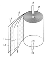
- FIG. 2 is a perspective view of a winding type electrode body included in the secondary battery shown in FIG.
- FIG. 3 is a front view showing a positive electrode and a negative electrode constituting an electrode body, which is an example of the embodiment, in an unfolded state.
- FIG. 1 is an axial sectional view of a cylindrical secondary battery 10 which is an example of an embodiment.
- an electrode body 14 and a non-aqueous electrolyte (not shown) are housed in an exterior body 15.
- the electrode body 14 has a winding structure in which the positive electrode 11 and the negative electrode 12 are wound via the separator 13.
- the non-aqueous solvent (organic solvent) of the non-aqueous electrolyte carbonates, lactones, ethers, ketones, esters and the like can be used, and two or more of these solvents can be mixed and used. ..
- a mixed solvent containing a cyclic carbonate and a chain carbonate For example, ethylene carbonate (EC), propylene carbonate (PC), butylene carbonate (BC) and the like can be used as the cyclic carbonate, and dimethyl carbonate (DMC), ethyl methyl carbonate (EMC), and diethyl carbonate (diethyl carbonate) can be used as the chain carbonate. DEC) and the like can be used.
- DEC dimethyl carbonate
- EMC ethyl methyl carbonate
- diethyl carbonate diethyl carbonate
- electrolyte salt of the non-aqueous electrolyte LiPF 6 , LiBF 4 , LiCF 3 SO 3 , etc. and a mixture thereof can be used.
- the amount of the electrolyte salt dissolved in the non-aqueous solvent can be, for example, 0.5 to 2.0 mol / L.
- the sealing body 16 side will be referred to as “top” and the bottom side of the exterior body 15 will be referred to as “bottom”.
- the inside of the secondary battery 10 is sealed by closing the opening end of the exterior body 15 with the sealing body 16.
- Insulating plates 17 and 18 are provided above and below the electrode body 14, respectively.
- the positive electrode lead 19 extends upward through the through hole of the insulating plate 17 and is welded to the lower surface of the filter 22 which is the bottom plate of the sealing body 16.
- the cap 26, which is the top plate of the sealing body 16 electrically connected to the filter 22, serves as a positive electrode terminal.
- the negative electrode lead 20 extends to the bottom side of the exterior body 15 through the through hole of the insulating plate 18 and is welded to the inner surface of the bottom portion of the exterior body 15.
- the exterior body 15 serves as a negative electrode terminal.
- the negative electrode 12 is located on the outermost peripheral surface of the electrode body 14, and the negative electrode 12 is in contact with the exterior body 15.
- the exterior body 15 is, for example, a metal exterior can having a bottomed cylindrical shape.
- a gasket 27 is provided between the exterior body 15 and the sealing body 16 to ensure the internal airtightness of the secondary battery 10.
- the exterior body 15 has a grooved portion 21 that supports the sealing body 16 and is formed by pressing, for example, a side surface portion from the outside.
- the grooved portion 21 is preferably formed in an annular shape along the circumferential direction of the exterior body 15, and the sealing body 16 is supported on the upper surface thereof.
- the sealing body 16 has a filter 22, a lower valve body 23, an insulating member 24, an upper valve body 25, and a cap 26, which are laminated in order from the electrode body 14 side.
- Each member constituting the sealing body 16 has, for example, a disk shape or a ring shape, and each member except the insulating member 24 is electrically connected to each other.
- the lower valve body 23 and the upper valve body 25 are connected to each other at the central portion thereof, and an insulating member 24 is interposed between the peripheral portions thereof.
- FIG. 2 is a perspective view of the winding type electrode body 14 included in the secondary battery 10 shown in FIG.
- the electrode body 14 is composed of a band-shaped positive electrode 11, a band-shaped negative electrode 12, two band-shaped separators 13, a positive electrode lead 19 bonded to the positive electrode 11, and a negative electrode lead 20 bonded to the negative electrode 12.
- the positive electrode 11, the negative electrode 12, and the separator 13 are spirally wound around the winding shaft so that the electrode body 14 is alternately laminated in the radial direction.
- the two separators 13 are formed to have a size one size larger than that of the positive electrode 11, and are arranged so as to sandwich the positive electrode 11.
- the negative electrode 12 is exposed on the outermost circumference of the electrode body 14.
- the winding shaft side is referred to as an inner peripheral side, and the opposite side thereof is referred to as an outer peripheral side.
- the longitudinal direction of the positive electrode 11 and the negative electrode 12 is the winding direction
- the band width direction of the positive electrode 11 and the negative electrode 12 is the axial direction.
- the positive electrode lead 19 extends axially from substantially the center in the radial direction between the center and the outermost periphery at the upper end of the electrode body 14.
- the negative electrode lead 20 extends in the axial direction from the vicinity of the winding shaft at the lower end of the electrode body 14.
- a porous sheet having ion permeability and insulating property is used for the separator 13.
- the porous sheet include a microporous thin film, a woven fabric, and a non-woven fabric.
- an olefin resin such as polyethylene or polypropylene is preferable.
- the thickness of the separator 13 is, for example, 10 ⁇ m to 50 ⁇ m.
- the separator 13 tends to be thinned as the capacity and output of the battery increase.
- the separator 13 has a melting point of, for example, about 130 ° C to 180 ° C.
- FIG. 3 is a front view showing the positive electrode 11 and the negative electrode 12 in an unfolded state.
- the negative electrode 12 is formed larger than the positive electrode 11 in order to prevent the precipitation of lithium on the negative electrode 12.
- the length of the negative electrode 12 in the band width direction is larger than the length of the positive electrode 11 in the band width direction.
- the length of the negative electrode 12 in the longitudinal direction is larger than the length of the positive electrode 11 in the longitudinal direction.
- the positive electrode 11 has a band-shaped positive electrode current collector 30 and a positive electrode mixture layer 32 formed on both sides of the positive electrode current collector 30.
- a positive electrode current collector 30 for example, a metal foil such as aluminum, a film on which the metal is arranged on the surface layer, or the like is used.
- the thickness of the positive electrode current collector 30 is, for example, 10 ⁇ m to 30 ⁇ m.
- the positive electrode mixture layer 32 is formed on both sides of the positive electrode current collector 30 in the entire area except for the positive electrode current collector exposed portion 34, which will be described later.
- the positive electrode mixture layer 32 preferably contains a positive electrode active material, a conductive agent, and a binder.
- the positive electrode mixture layer 32 is formed by applying a positive electrode mixture slurry containing a positive electrode active material, a conductive agent, a binder, and a solvent such as N-methyl-2-pyrrolidone (NMP) to both surfaces of the positive electrode current collector 30. , Made by drying and compressing the positive electrode mixture layer 32.
- NMP N-methyl-2-pyrrolidone
- a positive electrode current collector exposed portion 34 is provided at the central portion in the longitudinal direction of the positive electrode 11 over the entire length in the band width direction. This improves the current collecting property.
- the positive electrode current collector exposed portion 34 is a portion where the surface of the positive electrode current collector 30 is not covered with the positive electrode mixture layer 32.
- the positive electrode current collector exposed portion 34 is provided, for example, by intermittent application in which the positive electrode mixture slurry is not applied to a part of the positive electrode current collector 30.
- One end of the positive electrode lead 19 is connected to the positive electrode current collector exposed portion 34 by ultrasonic welding or the like. From the viewpoint of workability of the connection work of the positive electrode lead 19, it is preferable that the positive electrode current collector exposed portion 34 is provided on both sides of the positive electrode 11 so as to overlap with each other in the thickness direction of the positive electrode 11.
- the other end of the positive electrode lead 19 When the other end of the positive electrode lead 19 is wound as the electrode body 14, it extends upward from the end face in the band width direction at the radial intermediate position of the electrode body 14.
- the position of the positive electrode lead 19 is not particularly limited to the example shown in FIG. 3, and may be, for example, an inner end portion or an outer winding end portion.
- Examples of the positive electrode active material contained in the positive electrode mixture layer 32 include lithium-containing transition metal oxides containing transition metal elements such as Co, Mn, and Ni.
- the lithium-containing transition metal oxide is not particularly limited, but is limited to the general formula Li 1 + x MO 2 (in the formula, ⁇ 0.2 ⁇ x ⁇ 0.2, M contains at least one of Ni, Co, Mn, and Al). It is preferably a composite oxide represented by.
- Examples of the conductive agent contained in the positive electrode mixture layer 32 include carbon materials such as carbon black (CB), acetylene black (AB), Ketjen black, and graphite.
- binder contained in the positive electrode mixture layer 32 examples include fluororesins such as polytetrafluoroethylene (PTFE) and polyvinylidene fluoride (PVdF), polyacrylonitrile (PAN), polyimide (PI), acrylic resins, and polyolefins.
- fluororesins such as polytetrafluoroethylene (PTFE) and polyvinylidene fluoride (PVdF), polyacrylonitrile (PAN), polyimide (PI), acrylic resins, and polyolefins.
- system resins One of these may be used alone, or two or more of them may be used in combination. Further, these resins may be used in combination with carboxymethyl cellulose (CMC) or a salt thereof, polyethylene oxide (PEO) and the like.
- CMC carboxymethyl cellulose
- PEO polyethylene oxide
- the negative electrode 12 has a band-shaped negative electrode current collector 40 and a negative electrode mixture layer 42 formed on both sides of the negative electrode current collector 40.
- a metal foil such as copper, a film on which the metal is arranged on the surface layer, or the like is used.
- the thickness of the negative electrode current collector 40 is, for example, 5 ⁇ m to 30 ⁇ m.
- the negative electrode mixture layer 42 is formed on both sides of the negative electrode current collector 40 over the entire area excluding the negative electrode current collector exposed portion 44 described later.
- the negative electrode mixture layer 42 preferably contains a negative electrode active material and a binder.
- the negative electrode mixture layer 42 is formed by applying a negative electrode mixture slurry containing a negative electrode active material, a binder, and a solvent such as water to both surfaces of the negative electrode current collector 40, and then drying and compressing the negative electrode mixture layer 42. Is produced by.
- the negative electrode current collector exposed portion 44 is provided at the winding inner end portion 12a and the winding outer end portion 12b in the longitudinal direction of the negative electrode 12 over the entire length in the band width direction of the current collector.
- the negative electrode current collector exposed portion 44 is a portion where the surface of the negative electrode current collector 40 is not covered with the negative electrode mixture layer 42.
- the negative electrode current collector exposed portion 44 is provided, for example, by intermittent coating without applying the negative electrode mixture slurry to a part of the negative electrode current collector 40.
- One end of the negative electrode lead 20 is connected to the negative electrode current collector exposed portion 44 of the winding inner end portion 12a by ultrasonic welding or the like. From the viewpoint of workability of the connection work of the negative electrode lead 20, it is preferable that the negative electrode current collector exposed portion 44 is provided on both sides of the negative electrode 12 so as to overlap with each other in the thickness direction of the negative electrode 12.
- the other end of the negative electrode lead 20 When the other end of the negative electrode lead 20 is wound as the electrode body 14, it extends downward from the end face in the band width direction near the center of the winding axis of the electrode body 14.
- the arrangement position of the negative electrode lead 20 is not particularly limited to the example shown in FIG. 3, and the negative electrode current collector exposed portion 44 can be provided according to the arrangement position of the negative electrode lead 20.
- the negative electrode lead 20 may be provided at the unwinding end portion 12b of the negative electrode 12.
- the negative electrode current collector exposed portion 44 of the winding outer end portion 12b is located on the outermost peripheral surface of the electrode body 14 and is in contact with the exterior body 15. As a result, a current path to the negative electrode terminal is secured in addition to the negative electrode lead 20, so that the output characteristics of the battery are improved. It is more preferable that the negative electrode current collector 40 is exposed on the entire outer peripheral surface of the electrode body 14. As a result, the contact area between the negative electrode current collector exposed portion 44 and the exterior body 15 increases, so that the output characteristics of the battery are further improved.
- the length of the negative electrode current collector exposed portion 44 in the longitudinal direction may be larger than the length of the outermost peripheral surface of the electrode body 14.
- the negative electrode mixture layer 42 contains a first negative electrode active material and a second negative electrode active material having a larger expansion rate during charging than the first negative electrode active material.
- the first negative electrode active material may be, for example, a carbon-based material such as natural graphite or artificial graphite.
- the second negative electrode active material may be, for example, a metal alloying with lithium such as Si or Sn, an alloy containing these, an oxide or the like.
- the second negative electrode active material is preferably a Si-based material. Examples of the Si-based material include Si, an alloy containing Si, and a silicon oxide represented by SiO x (x is 0.8 to 1.6). Since the second negative electrode active material can occlude more lithium ions than the first negative electrode active material, the capacity of the battery can be increased by using the second negative electrode active material as the negative electrode active material.
- the second negative electrode active material ratio when the ratio of the mass of the second negative electrode active material to the total mass of the first negative electrode active material and the second negative electrode active material is defined as the second negative electrode active material ratio, in the electrode body 14, the second negative electrode active material is on the winding inner end portion 12a side.
- the ratio of the two negative electrode active materials is smaller than the ratio of the second negative electrode active material on the winding outer end portion 12b side.
- the ratio of the second negative electrode active material may decrease at a constant rate from the winding outer end portion 12b side to the winding inner end portion 12a side, or between the winding outer end portion 12b side and the winding inner end portion 12a side.
- the rate of decrease may change.
- the ratio of the second negative electrode active material is constant from the winding outer end portion 12b side to the winding inner end portion 12a side due to the ease of manufacturing. It is preferable that the amount is decreasing at the rate of.
- the ratio of the mass of the second negative electrode active material to the total mass of the first negative electrode active material and the second negative electrode active material in the entire negative electrode mixture layer 42 is preferably 2% by mass to 20% by mass, preferably 5% by mass to 15% by mass. % Is more preferable. Within this range, the reliability of the battery can be further improved while increasing the capacity of the battery.
- a fluororesin such as PTFE or PVdF, a PAN, PI, an acrylic resin, a polyolefin resin or the like may be used as in the case of the positive electrode 11.
- Styrene-butadiene rubber (SBR) is preferably used.
- the negative electrode mixture layer 42 may contain CMC or a salt thereof, polyacrylic acid (PAA) or a salt thereof, polyvinyl alcohol (PVA) or the like as a thickener. One of these may be used alone, or two or more of them may be used in combination.
- the content of the binder in the negative electrode mixture layer 42 may be, for example, 0.5% by mass to 10% by mass.
- the negative electrode mixture layer 42 can be formed, for example, by using a multilayer die coater.
- a multilayer die coater By using the multilayer die coater, a plurality of negative electrode mixture slurries having different ratios of the second negative electrode active materials can be simultaneously applied to the negative electrode current collector 40 while adjusting their application amount ratios.
- the negative electrode mixture slurry is applied to the negative electrode current collector 40, the negative electrode current collector 40 moves relative to the multilayer die coater. Therefore, a plurality of negative electrode mixture slurrys having different ratios of the second negative electrode active materials are applied to the negative electrode current collector 40 while changing their coating amount ratios at predetermined timings, thereby winding from the winding inner end portion 12a side.
- a region in which the ratio of the second negative electrode active material changes toward the outer end portion 12b can be formed at an arbitrary position of the negative electrode mixture layer 42.
- a first negative electrode mixture slurry and a second negative electrode mixture slurry having a smaller ratio of the second negative electrode active material than the first negative electrode mixture slurry are prepared.
- the first and second negative electrode mixture slurrys are wound on the inner end portion 12a side while increasing the coating amount ratio of the first negative electrode mixture slurry to the second negative electrode mixture slurry.
- a negative electrode mixture layer 42 in which the ratio of the second negative electrode active material is reduced at a constant ratio from the winding outer end portion 12b side to the winding inner end portion 12a side can be obtained.
- the amount of the first and second negative electrode mixture slurry applied may be adjusted so that the charge capacity per unit area of the negative electrode mixture layer 42 is constant in the longitudinal direction of the negative electrode 12.
- the ratio of the second negative electrode active material is smaller on the winding inner end portion 12a side than on the winding outer end portion 12b side, the coating on the winding inner end portion 12a side is smaller than that on the winding outer end portion 12b side.
- the charge capacity per unit area of the negative electrode mixture layer 42 can be made constant in the longitudinal direction of the negative electrode 12.
- Example 1 [Preparation of positive electrode] 100 parts by mass of LiNi 0.88 Co 0.09 Al 0.03 O 2 , 1 part by mass of acetylene black (AB) and 0.9 parts by mass of polyvinylidene fluoride (PVdF) were mixed and N- An appropriate amount of methyl-2-pyrrolidone (NMP) was added to prepare a positive electrode mixture slurry. Next, the positive electrode mixture slurry was applied to both sides of a strip-shaped positive electrode current collector made of aluminum foil having a thickness of 15 ⁇ m, the coating film was dried, and then the dried coating film was compressed using a roll press machine. The total thickness was 0.144 mm.
- NMP methyl-2-pyrrolidone
- the positive electrode is cut into a width of 62.6 mm and a length of 861 mm, and a positive electrode having a positive electrode current collector exposed portion at a substantially central portion in the longitudinal direction and a positive electrode mixture layer formed on both sides of the positive electrode current collector is produced. did. Then, one end of the aluminum positive electrode lead was welded to the exposed portion of the positive electrode current collector.
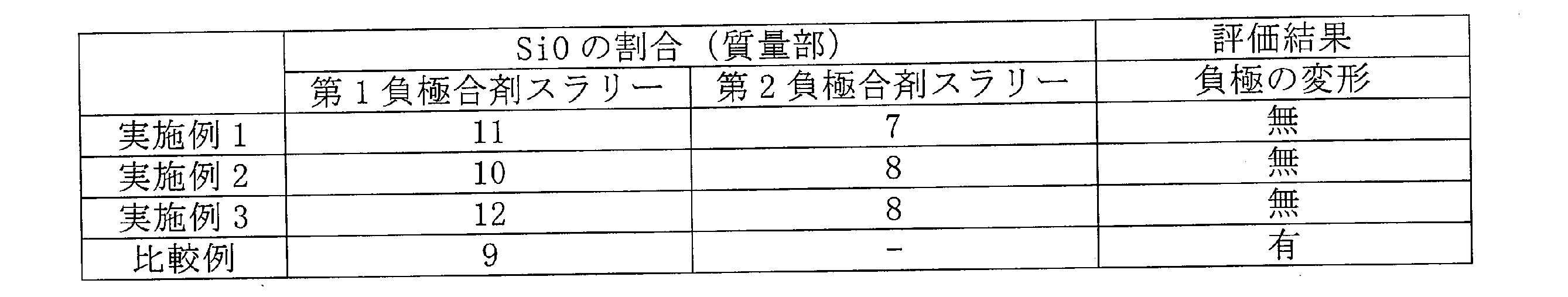
- a mixture A of 89 parts by mass of graphite and 11 parts by mass of SiO was used as the negative electrode active material.
- a 100 parts by mass of the mixture A, 1 part by mass of carboxymethyl cellulose (CMC) and 1 part by mass of styrene butadiene rubber (SBR) were mixed, and an appropriate amount of water was added to prepare a first negative electrode mixture slurry. ..
- a mixture B of 93 parts by mass of graphite and 7 parts by mass of SiO was used as the negative electrode active material.
- a second negative electrode mixture slurry was prepared by mixing 100 parts by mass of the mixture B, 1 part by mass of CMC, and 1 part by mass of SBR, and adding an appropriate amount of water.
- the first negative electrode mixture slurry and the second negative electrode mixture slurry were set on the multilayer die coater, and both sides of the strip-shaped negative electrode current collector made of copper foil having a thickness of 8 ⁇ m were placed on both sides of the winding inner end side. Charging per unit area in the longitudinal direction while continuously changing the coating amount ratio of the first negative electrode mixture slurry and the second negative electrode mixture slurry from 0: 1 to 1: 0 toward the outer end of the winding. The coating was applied so that the capacity was constant, and then the coating film was dried.
- Electrode body The positive electrode and the negative electrode were wound around the positive electrode and the negative electrode through a polyethylene separator to prepare an electrode body. The outermost peripheral surface of the electrode body was covered with an exposed portion of the negative electrode current collector. A polypropylene tape having a width of 12 mm, a thickness of 30 ⁇ m, and a length of 50 mm was attached to each of the upper end portion and the lower end portion of the outermost peripheral surface of the electrode body.
- Insulating plates were arranged above and below one electrode body, and the electrode body was housed in the exterior body.
- the negative electrode lead was welded to the bottom of the exterior body, and the positive electrode lead was welded to the sealing body.
- the open end of the exterior body was sealed so as to be crimped to the sealing body through a gasket to prepare a cylindrical secondary battery.
- the capacity of the manufactured battery was 4600 mAh.
- Example 2 Example 1 except that a mixture of 90 parts by mass of graphite and 10 parts by mass of SiO was used as the mixture A and a mixture of 92 parts by mass of graphite and 8 parts by mass of SiO was used as the mixture B in the preparation of the negative electrode.
- the battery was manufactured in the same manner as above.
- Example 3 Example 1 except that a mixture of 88 parts by mass of graphite and 12 parts by mass of SiO was used as the mixture A and a mixture of 92 parts by mass of graphite and 8 parts by mass of SiO was used as the mixture B in the preparation of the negative electrode.
- the battery was manufactured in the same manner as above.
- Table 1 shows the evaluation results of Examples and Comparative Examples. Table 1 also shows the proportion of SiO in the first and second negative electrode mixture slurries.
Landscapes
- Chemical & Material Sciences (AREA)
- Chemical Kinetics & Catalysis (AREA)
- Electrochemistry (AREA)
- General Chemical & Material Sciences (AREA)
- Engineering & Computer Science (AREA)
- Materials Engineering (AREA)
- Manufacturing & Machinery (AREA)
- Inorganic Chemistry (AREA)
- Composite Materials (AREA)
- Secondary Cells (AREA)
Abstract
Description
[正極の作製]
100質量部のLiNi0.88Co0.09Al0.03O2と、1質量部のアセチレンブラック(AB)と、0.9質量部のポリフッ化ビニリデン(PVdF)とを混合し、N-メチル-2-ピロリドン(NMP)を適量加えて、正極合剤スラリーを調製した。次に、当該正極合剤スラリーを厚み15μmのアルミニウム箔からなる帯状の正極集電体の両面に塗布し、塗膜を乾燥させた後に、ロールプレス機を用いて乾燥した塗膜を圧縮して、全体の厚みを0.144mmとした。さらに、幅62.6mm、長さ861mmに切断し、長手方向の略中央部に正極集電体露出部を有しつつ、正極集電体の両面に正極合剤層が形成された正極を作製した。その後、正極集電体露出部にアルミニウム製の正極リードの一端を溶接した。
負極活物質として、89質量部の黒鉛と、11質量部のSiOとの混合物Aを用いた。100質量部の混合物Aと、1質量部のカルボキシメチルセルロース(CMC)と、1質量部のスチレンブタジエンゴム(SBR)とを混合し、水を適量加えて、第1の負極合剤スラリーを調製した。また、負極活物質として、93質量部の黒鉛と、7質量部のSiOとの混合物Bを用いた。100質量部の混合物Bと、1質量部のCMCと、1質量部のSBRとを混合し、水を適量加えて、第2の負極合剤スラリーを調製した。次に、第1の負極合剤スラリー及び第2の負極合剤スラリーを多層ダイコーターにセットして、厚み8μmの銅箔からなる帯状の負極集電体の両面に、巻内端部側から巻外端部側にかけて、第1の負極合剤スラリーと第2の負極合剤スラリーの塗布量比を0:1から1:0まで連続的に変化させつつ、長手方向で単位面積当たりの充電容量が一定となるように塗布し、その後に塗膜を乾燥させた。ロールプレス機を用いて乾燥した塗膜を圧縮して全体の厚みを0.160mmとした後、幅64.2mm、長さ959mmに切断し、長手方向の巻内端部及び巻外端部に負極集電体露出部を有しつつ、負極集電体の両面に負極合剤層が形成された負極を作製した。その後、巻内端部の負極集電体露出部にニッケル/銅製の負極リードの一端を溶接した。
ポリエチレン製のセパレータを介して上記の正極及び負極を巻回して電極体を作製した。電極体の最外周面は、負極集電体露出部で覆われていた。電極体の最外周面の上端部と下端部の各々に、幅12mm、厚み30μ、長さ50mmのポリプロピレン製のテープを貼着した。
エチレンカーボネート(EC)と、ジメチルメチルカーボネート(DMC)とからなる混合溶媒(体積比でEC:DMC=1:3)の100質量部に、ビニレンカーボネート(VC)を5質量部添加した。当該混合溶媒に1.5モル/Lの濃度になるようにLiPF6を溶解させて、電解液を調製した。
1つの電極体の上と下とに絶縁板をそれぞれ配置し、電極体を外装体に収容した。次いで、負極リードを外装体の底部に溶接するとともに、正極リードを封口体に溶接した。その後、外装体の内部に電解液を減圧方式により注入した後、外装体の開口端部を、ガスケットを介して封口体にかしめるように封口して、円筒形二次電池を作製した。作製した電池の容量は、4600mAhであった。
負極の作製において、混合物Aとして90質量部の黒鉛と10質量部のSiOの混合物を用い、混合物Bとして92質量部の黒鉛と8質量部のSiOの混合物を用いたこと以外は、実施例1と同様にして電池を作製した。
負極の作製において、混合物Aとして88質量部の黒鉛と12質量部のSiOの混合物を用い、混合物Bとして92質量部の黒鉛と8質量部のSiOの混合物を用いたこと以外は、実施例1と同様にして電池を作製した。
負極の作製において、混合物Aとして91質量部の黒鉛と9質量部のSiOの混合物を用い、第1の負極合剤スラリーのみを負極集電体の両面に塗布したこと以外は、実施例1と同様にして電池を作製した。
実施例及び比較例の電池を、45℃の温度環境において、電池電圧が4.2Vになるまで0.3C(=1380mA)で定電流充電を行い、その後、電流値が0.02C(=92mA)になるまで4.2Vで定電圧充電を行った。次いで、電池電圧が2.5Vになるまで0.5C(=2300mA)で定電流放電を行い、これを1サイクルとした。この充放電サイクルを1000サイクル繰り返した後に、電池電圧が4.2Vになるまで0.3Cで定電流充電を行い、その後、電流値が0.02Cになるまで4.2Vで定電圧充電を行った。X線CT(Computed Tomography)装置を用いて、当該電池の電極体の巻内端部近傍の断面観察を実施し、負極の変形の有無を確認した。
Claims (2)
- 正極及び負極がセパレータを介して巻回された電極体と、非水電解質と、前記電極体及び前記非水電解質を収容する外装体とを備える非水電解質二次電池であって、
前記負極は、第1負極活物質と、前記第1負極活物質よりも充電時の膨張率が大きい第2負極活物質とを含み、
前記第1負極活物質と前記第2負極活物質との合計質量に対する前記第2負極活物質の質量の割合を第2負極活物質比率とした場合に、巻内端部側の第2負極活物質比率は、巻外端部側の第2負極活物質比率より小さい、非水電解質二次電池。 - 前記第1負極活物質は、炭素系材料であり、
前記第2負極活物質は、ケイ素系材料である、請求項1に記載の非水電解質二次電池。
Priority Applications (4)
| Application Number | Priority Date | Filing Date | Title |
|---|---|---|---|
| EP21849440.9A EP4191697A4 (en) | 2020-07-31 | 2021-07-09 | SECONDARY BATTERY WITH NON-AQUEOUS ELECTROLYTE |
| JP2022540125A JP7763174B2 (ja) | 2020-07-31 | 2021-07-09 | 非水電解質二次電池 |
| US18/017,331 US20230299434A1 (en) | 2020-07-31 | 2021-07-09 | Nonaqueous electrolyte secondary battery |
| CN202180060180.0A CN116137936A (zh) | 2020-07-31 | 2021-07-09 | 非水电解质二次电池 |
Applications Claiming Priority (2)
| Application Number | Priority Date | Filing Date | Title |
|---|---|---|---|
| JP2020129866 | 2020-07-31 | ||
| JP2020-129866 | 2020-07-31 |
Publications (1)
| Publication Number | Publication Date |
|---|---|
| WO2022024712A1 true WO2022024712A1 (ja) | 2022-02-03 |
Family
ID=80036297
Family Applications (1)
| Application Number | Title | Priority Date | Filing Date |
|---|---|---|---|
| PCT/JP2021/025880 Ceased WO2022024712A1 (ja) | 2020-07-31 | 2021-07-09 | 非水電解質二次電池 |
Country Status (5)
| Country | Link |
|---|---|
| US (1) | US20230299434A1 (ja) |
| EP (1) | EP4191697A4 (ja) |
| JP (1) | JP7763174B2 (ja) |
| CN (1) | CN116137936A (ja) |
| WO (1) | WO2022024712A1 (ja) |
Cited By (4)
| Publication number | Priority date | Publication date | Assignee | Title |
|---|---|---|---|---|
| WO2022190895A1 (ja) * | 2021-03-08 | 2022-09-15 | 三洋電機株式会社 | 非水電解質二次電池 |
| WO2024248105A1 (ja) | 2023-05-31 | 2024-12-05 | パナソニックIpマネジメント株式会社 | 二次電池 |
| WO2025204898A1 (ja) * | 2024-03-27 | 2025-10-02 | パナソニックIpマネジメント株式会社 | 二次電池用負極および二次電池 |
| WO2026048293A1 (ja) * | 2024-08-30 | 2026-03-05 | パナソニックIpマネジメント株式会社 | 二次電池用負極および二次電池 |
Families Citing this family (1)
| Publication number | Priority date | Publication date | Assignee | Title |
|---|---|---|---|---|
| CN116682936B (zh) * | 2023-08-04 | 2024-01-12 | 宁德时代新能源科技股份有限公司 | 电池及其制备方法、用电装置 |
Citations (8)
| Publication number | Priority date | Publication date | Assignee | Title |
|---|---|---|---|---|
| JP2007149441A (ja) * | 2005-11-25 | 2007-06-14 | Toyota Motor Corp | 捲回型蓄電装置 |
| JP2009070658A (ja) * | 2007-09-12 | 2009-04-02 | Nec Tokin Corp | 非水電解質二次電池 |
| JP2010212228A (ja) | 2009-02-13 | 2010-09-24 | Hitachi Maxell Ltd | 非水二次電池 |
| JP2013178913A (ja) | 2012-02-28 | 2013-09-09 | Hitachi Maxell Ltd | 非水電解液二次電池 |
| JP2016012541A (ja) * | 2014-06-30 | 2016-01-21 | 株式会社豊田自動織機 | 蓄電装置及び蓄電装置の製造方法 |
| WO2019230298A1 (ja) * | 2018-05-30 | 2019-12-05 | パナソニックIpマネジメント株式会社 | 非水電解質二次電池 |
| WO2019230297A1 (ja) * | 2018-05-30 | 2019-12-05 | パナソニックIpマネジメント株式会社 | 非水電解質二次電池 |
| WO2020044930A1 (ja) * | 2018-08-29 | 2020-03-05 | パナソニックIpマネジメント株式会社 | 非水電解質二次電池 |
Family Cites Families (5)
| Publication number | Priority date | Publication date | Assignee | Title |
|---|---|---|---|---|
| CN106030862A (zh) * | 2014-03-25 | 2016-10-12 | 三洋电机株式会社 | 非水电解质二次电池用负极板及非水电解质二次电池 |
| CN107408725B (zh) * | 2015-02-27 | 2020-02-07 | 三洋电机株式会社 | 非水电解质二次电池 |
| WO2016147564A1 (ja) * | 2015-03-13 | 2016-09-22 | 三洋電機株式会社 | 非水電解質二次電池 |
| CN108352491B (zh) * | 2015-11-19 | 2021-01-08 | 三洋电机株式会社 | 非水电解质二次电池 |
| JP7024791B2 (ja) * | 2017-07-24 | 2022-02-24 | 株式会社村田製作所 | 二次電池用負極、二次電池、電池パック、電動車両、電力貯蔵システム、電動工具および電子機器 |
-
2021
- 2021-07-09 WO PCT/JP2021/025880 patent/WO2022024712A1/ja not_active Ceased
- 2021-07-09 US US18/017,331 patent/US20230299434A1/en active Pending
- 2021-07-09 JP JP2022540125A patent/JP7763174B2/ja active Active
- 2021-07-09 CN CN202180060180.0A patent/CN116137936A/zh active Pending
- 2021-07-09 EP EP21849440.9A patent/EP4191697A4/en active Pending
Patent Citations (8)
| Publication number | Priority date | Publication date | Assignee | Title |
|---|---|---|---|---|
| JP2007149441A (ja) * | 2005-11-25 | 2007-06-14 | Toyota Motor Corp | 捲回型蓄電装置 |
| JP2009070658A (ja) * | 2007-09-12 | 2009-04-02 | Nec Tokin Corp | 非水電解質二次電池 |
| JP2010212228A (ja) | 2009-02-13 | 2010-09-24 | Hitachi Maxell Ltd | 非水二次電池 |
| JP2013178913A (ja) | 2012-02-28 | 2013-09-09 | Hitachi Maxell Ltd | 非水電解液二次電池 |
| JP2016012541A (ja) * | 2014-06-30 | 2016-01-21 | 株式会社豊田自動織機 | 蓄電装置及び蓄電装置の製造方法 |
| WO2019230298A1 (ja) * | 2018-05-30 | 2019-12-05 | パナソニックIpマネジメント株式会社 | 非水電解質二次電池 |
| WO2019230297A1 (ja) * | 2018-05-30 | 2019-12-05 | パナソニックIpマネジメント株式会社 | 非水電解質二次電池 |
| WO2020044930A1 (ja) * | 2018-08-29 | 2020-03-05 | パナソニックIpマネジメント株式会社 | 非水電解質二次電池 |
Non-Patent Citations (1)
| Title |
|---|
| See also references of EP4191697A4 |
Cited By (4)
| Publication number | Priority date | Publication date | Assignee | Title |
|---|---|---|---|---|
| WO2022190895A1 (ja) * | 2021-03-08 | 2022-09-15 | 三洋電機株式会社 | 非水電解質二次電池 |
| WO2024248105A1 (ja) | 2023-05-31 | 2024-12-05 | パナソニックIpマネジメント株式会社 | 二次電池 |
| WO2025204898A1 (ja) * | 2024-03-27 | 2025-10-02 | パナソニックIpマネジメント株式会社 | 二次電池用負極および二次電池 |
| WO2026048293A1 (ja) * | 2024-08-30 | 2026-03-05 | パナソニックIpマネジメント株式会社 | 二次電池用負極および二次電池 |
Also Published As
| Publication number | Publication date |
|---|---|
| CN116137936A (zh) | 2023-05-19 |
| JPWO2022024712A1 (ja) | 2022-02-03 |
| US20230299434A1 (en) | 2023-09-21 |
| EP4191697A4 (en) | 2025-01-22 |
| JP7763174B2 (ja) | 2025-10-31 |
| EP4191697A1 (en) | 2023-06-07 |
Similar Documents
| Publication | Publication Date | Title |
|---|---|---|
| JP7763174B2 (ja) | 非水電解質二次電池 | |
| JPWO2019244818A1 (ja) | 非水電解質二次電池 | |
| WO2021039275A1 (ja) | 非水電解質二次電池 | |
| WO2018173899A1 (ja) | 非水電解質二次電池 | |
| EP4471927A1 (en) | Cylindrical nonaqueous electrolyte secondary battery | |
| WO2018105398A1 (ja) | 円筒形の非水電解質二次電池 | |
| JP7738017B2 (ja) | 非水電解質二次電池 | |
| JP7102348B2 (ja) | 液体電解質含有非水電解質二次電池用正極及び液体電解質含有非水電解質二次電池 | |
| WO2023100756A1 (ja) | 非水電解質二次電池 | |
| WO2018079292A1 (ja) | 非水電解質二次電池用電極及び非水電解質二次電池 | |
| JP7336680B2 (ja) | 二次電池 | |
| US20240145676A1 (en) | Nonaqueous electrolyte secondary battery | |
| US20240258555A1 (en) | Non-aqueous electrolyte secondary battery | |
| JP7726864B2 (ja) | 非水電解質二次電池および非水電解質二次電池用負極 | |
| JP7601772B2 (ja) | 非水電解質二次電池及び非水電解質二次電池の製造方法 | |
| JP7637645B2 (ja) | 非水電解質二次電池 | |
| WO2023145506A1 (ja) | 非水電解質二次電池 | |
| WO2021187348A1 (ja) | 非水電解質二次電池 | |
| EP4475214A1 (en) | Lithium ion battery | |
| WO2025142628A1 (ja) | 二次電池 | |
| WO2026048749A1 (ja) | 非水電解質二次電池 | |
| WO2025225437A1 (ja) | 非水電解質二次電池 | |
| WO2026070410A1 (ja) | 非水電解質二次電池 | |
| WO2025142954A1 (ja) | 円筒形リチウムイオン二次電池 | |
| WO2025182837A1 (ja) | 円筒形二次電池 |
Legal Events
| Date | Code | Title | Description |
|---|---|---|---|
| 121 | Ep: the epo has been informed by wipo that ep was designated in this application |
Ref document number: 21849440 Country of ref document: EP Kind code of ref document: A1 |
|
| ENP | Entry into the national phase |
Ref document number: 2022540125 Country of ref document: JP Kind code of ref document: A |
|
| WWE | Wipo information: entry into national phase |
Ref document number: 2021849440 Country of ref document: EP |
|
| ENP | Entry into the national phase |
Ref document number: 2021849440 Country of ref document: EP Effective date: 20230228 |
|
| NENP | Non-entry into the national phase |
Ref country code: DE |