WO2022025169A1 - バタフライバルブ - Google Patents
バタフライバルブ Download PDFInfo
- Publication number
- WO2022025169A1 WO2022025169A1 PCT/JP2021/028059 JP2021028059W WO2022025169A1 WO 2022025169 A1 WO2022025169 A1 WO 2022025169A1 JP 2021028059 W JP2021028059 W JP 2021028059W WO 2022025169 A1 WO2022025169 A1 WO 2022025169A1
- Authority
- WO
- WIPO (PCT)
- Prior art keywords
- valve
- valve body
- outer peripheral
- hole
- seat ring
- Prior art date
- Legal status (The legal status is an assumption and is not a legal conclusion. Google has not performed a legal analysis and makes no representation as to the accuracy of the status listed.)
- Ceased
Links
Images


Classifications
-
- F—MECHANICAL ENGINEERING; LIGHTING; HEATING; WEAPONS; BLASTING
- F16—ENGINEERING ELEMENTS AND UNITS; GENERAL MEASURES FOR PRODUCING AND MAINTAINING EFFECTIVE FUNCTIONING OF MACHINES OR INSTALLATIONS; THERMAL INSULATION IN GENERAL
- F16K—VALVES; TAPS; COCKS; ACTUATING-FLOATS; DEVICES FOR VENTING OR AERATING
- F16K1/00—Lift valves or globe valves, i.e. cut-off apparatus with closure members having at least a component of their opening and closing motion perpendicular to the closing faces
- F16K1/16—Lift valves or globe valves, i.e. cut-off apparatus with closure members having at least a component of their opening and closing motion perpendicular to the closing faces with pivoted closure-members
- F16K1/18—Lift valves or globe valves, i.e. cut-off apparatus with closure members having at least a component of their opening and closing motion perpendicular to the closing faces with pivoted closure-members with pivoted discs or flaps
- F16K1/22—Lift valves or globe valves, i.e. cut-off apparatus with closure members having at least a component of their opening and closing motion perpendicular to the closing faces with pivoted closure-members with pivoted discs or flaps with axis of rotation crossing the valve member, e.g. butterfly valves
- F16K1/222—Shaping of the valve member
-
- F—MECHANICAL ENGINEERING; LIGHTING; HEATING; WEAPONS; BLASTING
- F16—ENGINEERING ELEMENTS AND UNITS; GENERAL MEASURES FOR PRODUCING AND MAINTAINING EFFECTIVE FUNCTIONING OF MACHINES OR INSTALLATIONS; THERMAL INSULATION IN GENERAL
- F16K—VALVES; TAPS; COCKS; ACTUATING-FLOATS; DEVICES FOR VENTING OR AERATING
- F16K1/00—Lift valves or globe valves, i.e. cut-off apparatus with closure members having at least a component of their opening and closing motion perpendicular to the closing faces
- F16K1/16—Lift valves or globe valves, i.e. cut-off apparatus with closure members having at least a component of their opening and closing motion perpendicular to the closing faces with pivoted closure-members
- F16K1/18—Lift valves or globe valves, i.e. cut-off apparatus with closure members having at least a component of their opening and closing motion perpendicular to the closing faces with pivoted closure-members with pivoted discs or flaps
- F16K1/22—Lift valves or globe valves, i.e. cut-off apparatus with closure members having at least a component of their opening and closing motion perpendicular to the closing faces with pivoted closure-members with pivoted discs or flaps with axis of rotation crossing the valve member, e.g. butterfly valves
- F16K1/226—Shaping or arrangements of the sealing
- F16K1/2261—Shaping or arrangements of the sealing the sealing being arranged on the valve member
-
- F—MECHANICAL ENGINEERING; LIGHTING; HEATING; WEAPONS; BLASTING
- F16—ENGINEERING ELEMENTS AND UNITS; GENERAL MEASURES FOR PRODUCING AND MAINTAINING EFFECTIVE FUNCTIONING OF MACHINES OR INSTALLATIONS; THERMAL INSULATION IN GENERAL
- F16K—VALVES; TAPS; COCKS; ACTUATING-FLOATS; DEVICES FOR VENTING OR AERATING
- F16K1/00—Lift valves or globe valves, i.e. cut-off apparatus with closure members having at least a component of their opening and closing motion perpendicular to the closing faces
- F16K1/16—Lift valves or globe valves, i.e. cut-off apparatus with closure members having at least a component of their opening and closing motion perpendicular to the closing faces with pivoted closure-members
- F16K1/18—Lift valves or globe valves, i.e. cut-off apparatus with closure members having at least a component of their opening and closing motion perpendicular to the closing faces with pivoted closure-members with pivoted discs or flaps
- F16K1/22—Lift valves or globe valves, i.e. cut-off apparatus with closure members having at least a component of their opening and closing motion perpendicular to the closing faces with pivoted closure-members with pivoted discs or flaps with axis of rotation crossing the valve member, e.g. butterfly valves
- F16K1/226—Shaping or arrangements of the sealing
- F16K1/2263—Shaping or arrangements of the sealing the sealing being arranged on the valve seat
- F16K1/2265—Shaping or arrangements of the sealing the sealing being arranged on the valve seat with a channel- or U-shaped seal covering a central body portion
-
- F—MECHANICAL ENGINEERING; LIGHTING; HEATING; WEAPONS; BLASTING
- F16—ENGINEERING ELEMENTS AND UNITS; GENERAL MEASURES FOR PRODUCING AND MAINTAINING EFFECTIVE FUNCTIONING OF MACHINES OR INSTALLATIONS; THERMAL INSULATION IN GENERAL
- F16K—VALVES; TAPS; COCKS; ACTUATING-FLOATS; DEVICES FOR VENTING OR AERATING
- F16K25/00—Details relating to contact between valve members and seats
-
- F—MECHANICAL ENGINEERING; LIGHTING; HEATING; WEAPONS; BLASTING
- F16—ENGINEERING ELEMENTS AND UNITS; GENERAL MEASURES FOR PRODUCING AND MAINTAINING EFFECTIVE FUNCTIONING OF MACHINES OR INSTALLATIONS; THERMAL INSULATION IN GENERAL
- F16K—VALVES; TAPS; COCKS; ACTUATING-FLOATS; DEVICES FOR VENTING OR AERATING
- F16K27/00—Construction of housing; Use of materials therefor
- F16K27/02—Construction of housing; Use of materials therefor of lift valves
- F16K27/0209—Check valves or pivoted valves
- F16K27/0218—Butterfly valves
Definitions
- the present invention relates to a butterfly valve suitably used for piping lines of various industries such as chemical factories, water and sewage, agriculture / fisheries, semiconductor manufacturing fields, and food fields.
- the butterfly valve extends through the valve body in which the internal flow path is formed, the seat ring mounted on the inner peripheral surface of the internal flow path of the valve body, and is rotatably supported by the valve body.
- the valve body is provided with a valve shaft arranged in the seat ring and fixedly attached to the valve shaft so as to rotate with the valve shaft, and the valve body is rotated around the rotation axis in the valve body using the valve shaft.
- the valve is opened and closed by pressing and separating the outer peripheral surface of the valve body from the valve seat surface provided on the inner peripheral surface of the seat ring.
- the valve body is provided with a pair of bearing holes for inserting and supporting the valve shaft at positions facing each other in the radial direction of the internal flow path.
- the seat ring includes a ring body having a substantially tubular shape extending in the central axis direction and an annular flange portion provided at both ends in the center axis direction of the ring body and extending outward, and the internal flow of the valve body.
- a butterfly valve it is formed on the outer peripheral surface of the valve body and the inner peripheral surface of the seat ring arranged in the seat ring (specifically, the ring body thereof) mounted on the inner peripheral surface of the internal flow path.
- the internal flow path is blocked by the valve body by sealing the valve seat surface in close contact with the valve seat surface.
- the surface pressure that presses the outer peripheral surface against the valve seat surface is increased, the resistance when the valve body is rotated to press the outer peripheral surface of the valve body against the valve seat surface increases when the valve is closed.
- the operating torque of the valve shaft for rotating the valve body increases.
- it has a spherical shape having a radius slightly larger than the distance from the center of the valve body to the valve seat surface.
- a butterfly valve has been proposed in which the outer peripheral surface of the valve body is formed so that the outer peripheral surface is smoothly in contact with the valve seat surface.
- the butterfly valve when the outer peripheral surface of the valve body is pressed against the valve seat surface of the seat ring to seal it, the effective surface pressure becomes low near the through hole for penetrating the valve shaft. As a result, at the same seat ring compression rate, the sealing performance in the vicinity of the through hole is lowered and leakage is likely to occur. Therefore, for example, as in the butterfly valve described in Patent Document 2, the outer periphery of the ring body of the seat ring is formed in an elliptical shape with the valve axis direction as the major axis, and the inner circumference is formed in a circular shape. , A butterfly valve has been proposed in which the effective surface pressure near the through hole is increased and the sealing performance is improved by increasing the crushing allowance around the through hole.
- an object of the present invention is to solve the problems existing in the prior art, and to suppress an increase in the operating torque of the valve body at the time of closing the valve even with a large-diameter butterfly valve, while suppressing an increase in the operating torque between the valve body and the valve seat surface.
- the purpose is to ensure the required sealing performance.
- the present invention has a valve body in which an internal flow path extending in the flow path axis direction is formed, a seat ring mounted on the inner peripheral surface of the internal flow path, and rotation around the rotation axis.
- a valve shaft supported by the valve body and a substantially disk-shaped valve body connected to the valve shaft and rotatably supported by the valve body and arranged in the seat ring are provided around the rotation axis.
- a butterfly valve that opens and closes the internal flow path by rotating the valve body to bring the peripheral edge portion of the valve body into contact with the inner peripheral surface of the seat ring, and the valve body moves in the circumferential direction.
- valve body has an extending annular outer peripheral edge surface, and two valve shaft openings for inserting the valve shaft into the opposite positions on the outer peripheral edge surface in the direction of the rotation axis are formed, and the valve body is said to have the same valve body.
- On the outer peripheral surface there are two annular ridges protruding from the outer peripheral surface and extending along the peripheral edge of each valve shaft opening, and between the two opening ridges protruding from the outer peripheral surface.
- a peripheral edge ridge extending in the circumferential direction of the valve body is further provided so as to connect, and the peripheral edge ridge portion extends in an arc shape in the circumferential direction and flatly in the width direction along the top thereof.
- a butterfly having a chamfered surface that is inclined with respect to the peripheral edge sealing surface at a predetermined angle toward the outer peripheral edge surface of the valve body and extends along both sides of the peripheral edge sealing surface.
- a peripheral ridge portion protruding from the outer peripheral edge surface of the valve body extends in the circumferential direction along the top thereof, and a planar peripheral edge sealing surface and an outer peripheral edge of the valve body with respect to the peripheral edge sealing surface. It has a chamfered surface that is inclined at a predetermined angle toward the surface and extends along both sides of the peripheral sealing surface. Since the flat peripheral edge sealing surface formed on the top of the peripheral edge of the valve body is pressed against the inner peripheral surface of the seat ring, the pressure from the peripheral edge of the valve body to the inner peripheral surface of the seat ring is applied to the peripheral edge seal. The sealing pressure is increased by concentrating on the surface. Further, when the chamfered surface inclined with respect to the peripheral seal surface is formed along both sides of the peripheral seal surface, the valve body rotates and the peripheral edge raised portion comes into contact with the inner peripheral surface of the seat ring. Resistance can be reduced.
- the predetermined angle is preferably an angle in the range of 15 ° to 30 °.
- the width of the peripheral seal surface is preferably in the range of 3 mm to 10 mm.
- the seat ring includes an outer peripheral surface and an inner peripheral surface, and an annular projection protruding from the outer peripheral surface and extending in an annular shape, and the annular projection of the seat ring is provided on the inner peripheral surface of the internal flow path of the valve body. It is possible to provide an annular fitting groove for fitting.
- annular fitting groove is the two bearings. It includes two opening grooves provided on the peripheral edge of the opening of the hole and two peripheral grooves extending circumferentially so as to connect between the two opening grooves, one of the two peripheral grooves downstream. It is preferable that a chamfered portion is provided at the upper edge end portion on the side and a chamfered portion is provided at the upper end end portion on the upstream side of the other of the two peripheral grooves.
- the peripheral groove portion has a rectangular cross section, the chamfered portion is formed by an inclined surface, and the angle formed by the inclined surface and the extension surface of the side surface of the peripheral groove portion is when the butterfly valve is fully open.
- the rotation angle of the valve body is set to 0 °, it is determined to match the rotation angle of the valve body when the peripheral edge sealing surface and the inclined surface of the peripheral edge raised portion of the valve body come into contact with each other. It is more preferable to make it.
- the seat ring is formed with two through holes extending from the outer peripheral surface to the inner peripheral surface in order to penetrate the valve shaft at positions facing each other in the direction of the rotation axis.
- two annular through-hole sealing surfaces extending in a plane on the peripheral edge of each through-hole and a valve extending in an arc shape in the circumferential direction so as to connect between the two through-hole sealing surfaces.
- An inner peripheral transition surface connecting the seat surface and the through hole sealing surface and the valve seat surface is formed, and an annular opening seal extending to the top of the opening ridge is formed on the outer peripheral surface of the valve body.
- a surface and an outer peripheral transition surface connecting the opening seal surface and the peripheral edge seal surface are further formed, and the inner peripheral transition surface extends in an arc shape so as to be coaxial with the through hole.
- the inner peripheral transition surface comes into contact with the outer peripheral transition surface when the valve is closed.
- the valve seat surface formed on the inner peripheral surface of the seat ring has a concave shape forming a part of a spherical surface.
- annular protrusion is connected between the two annular through-hole protrusions provided on the peripheral edge of each through-hole on the outer peripheral surface of the seat ring and the two through-hole protrusions.
- a protrusion sealing surface extending in parallel with the through hole sealing surface is formed at the top of each through hole protrusion, including two outer peripheral protrusions extending in the circumferential direction, and the protrusion from the through hole sealing surface. It is preferable that the thickness to the sealing surface is equal to the thickness from the valve seat surface of the seat ring to the top of the outer peripheral protrusion.
- the seat ring is formed with two through holes extending from the outer peripheral surface to the inner peripheral surface in order to penetrate the valve shaft at positions facing each other in the direction of the rotation axis.
- two annular through-hole sealing surfaces extending in a plane on the peripheral edge of each through-hole and extending in an arc shape in the circumferential direction so as to connect between the two through-hole sealing surfaces. It is preferable that the valve seat surface is formed and the width of the annular protrusion is larger than the width of the valve seat surface.
- the valve body is adjacent to the bearing holes located on both sides of the rotation axis within a predetermined angle from the rotation axis around the center of the internal flow path. Meat is stolen on the outer periphery other than the area.
- the predetermined angle is preferably 40 ° or more and 60 ° or less.
- the flat peripheral edge sealing surface formed on the top of the peripheral edge of the valve body is pressed against the inner peripheral surface of the seat ring, so that the inner peripheral edge of the seat ring is pressed from the peripheral edge of the valve body.
- the pressure on the surface is concentrated on the peripheral sealing surface to increase the sealing pressure.
- the chamfered surface inclined with respect to the peripheral seal surface is formed along both sides of the peripheral seal surface, the valve body rotates and the peripheral edge raised portion comes into contact with the inner peripheral surface of the seat ring.
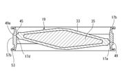
- FIG. 3 is a cross-sectional view showing a valve body shown in FIG. 2 cut along a horizontal cross section passing through the center of the valve body.
- FIG. 3 is an enlarged cross-sectional view showing an enlarged portion of the butterfly valve shown in FIG. 4 surrounded by a circle. It is a perspective view which shows the seat ring of the butterfly valve shown in FIG. FIG.
- FIG. 6 is a partially enlarged perspective view showing the structure of the seat ring shown in FIG. 6 in the vicinity of the through hole on the upper side in the drawing from the inner peripheral side. It is sectional drawing which shows the structure in the vicinity of the through hole of the seat ring shown in FIG. 7 in the cross section. It is sectional drawing which shows the state which the seat ring shown in FIG. 6 was cut in half up and down. 9 is an enlarged cross-sectional view showing an enlarged portion of the seat ring shown in FIG. 9 surrounded by a circle.
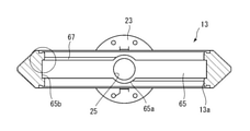
- FIG. 3 is a cross-sectional view showing the valve body of the butterfly valve shown in FIG. 1 as a horizontal cross-sectional surface passing through the center of the internal flow path.
- FIG. 3 is an enlarged cross-sectional view showing an enlarged portion surrounded by a circle shown in FIG.
- FIG. 1 is a vertical cross-sectional view of the butterfly valve when viewed from the flow path axial direction, and shows a valve closed state.
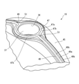
- FIG. 2 is a partial cross-sectional perspective view showing a cross section of the valve body of the butterfly valve shown in FIG. 1 by partially breaking the valve body.
- the butterfly valve 11 includes a substantially hollow cylindrical valve body 13 in which an internal flow path 13a extending in the direction of the flow path axis is formed, a valve shaft 15 rotatably supported by the valve body 13, and an internal flow path 13a.
- An annular seat ring 17 attached to the inner circumference and a valve body 19 arranged in the internal flow path 13a and connected to the valve shaft 15 and rotatably supported by the valve body 13 around the rotation axis R.
- a bush 21 made of a synthetic resin material that is rotatably externally inserted to the valve shaft 15 is provided, and an internal flow path is provided by bringing the inner peripheral surface of the seat ring 17 into contact with the outer peripheral edge of the valve body 19.
- the 13a can be opened and closed.
- the valve shaft 15 has a first valve shaft 15a arranged on the upper side in FIG. 1 and a second valve shaft 15 arranged on the lower side in FIG. 1 along the rotation axis R.
- the bush 21 is composed of the valve shaft 15b of the above, and the bush 21 is also rotatably externally attached to the first valve shaft 15a, the first bush 21a and the second valve shaft 15b. It is composed of 21b.
- the valve body 19 is rotatably supported by the valve body 13 by the first valve shaft 15a and the second valve shaft 15b via the first bush 21a and the second bush 21b, respectively.
- a drive unit (not shown) is connected to the first valve shaft 15a, and by rotating the first valve shaft 15a using the drive unit, the valve body 19 is rotated around the rotation axis R to open and close the valve. I do.
- the valve shaft 15 is composed of two valve shafts 15 of a first valve shaft 15a and a second valve shaft 15b, but the first valve shaft 15a and the second valve shaft 15a. It is also possible to integrally form the valve shaft 15b to form one valve shaft 15. Similarly, it is also possible to integrally form the first bush 21a and the second bush 21b to form one bush 21.
- the first valve shaft 15a and the second valve shaft 15b are formed of a metal material such as cast iron, steel, carbon steel, copper, copper alloy, brass, stainless steel, aluminum, and titanium, but there is a problem in strength.
- the material is not particularly limited as long as there is no such material.
- the valve body 13 is made of a synthetic resin material.
- the synthetic resin material include polyvinyl chloride (PVC), polypropylene (PP), polyvinylidene fluoride (PVDF), polyethylene (PE), polyphenylene sulfide (PPS), polydicyclopentadiene (PDCPD), and polytetrafluoroethylene (PTFE).
- a substantially disk-shaped top flange 23 is provided on the upper portion of the valve body 13. Further, in the valve body 13, a first bearing hole 25 and a second bearing extending from the internal flow path 13a to the outside facing each other in the radial direction (vertical direction in FIG. 1) of the internal flow path 13a. The holes 27 are formed.
- the first bearing hole 25 extends through the top flange 23.
- a first valve shaft 15a is inserted through the first bearing hole 25 with the first bush 21a externally inserted, and is rotatably supported in the first bearing hole 25 via the first bush 21a. Has been done.
- the upper end of the first valve shaft 15a inserted into the first bearing hole 25 protrudes from the top flange 23 and extends so as to be connected to a drive unit installed on the top flange 23. ..
- a drive unit for example, a lever type drive unit, a gear type drive unit, an automatic drive unit, or the like can be used.
- the lower ends of the first valve shaft 15a and the first bush 21a inserted into the first bearing hole 25 extend from the first bearing hole 25 so as to project toward the internal flow path 13a. ..
- the second valve shaft 15b is inserted into the second bearing hole 27 with the second bush 21b externally inserted, and rotates into the second bearing hole 27 via the second bush 21b. It is supported as much as possible.
- the lower end of the second bearing hole 27 is closed by the valve shaft holder 29, and the lower ends of the second valve shaft 15b and the second bush 21b inserted into the second bearing hole 27 are valve shaft holders. It is designed to come into contact with 29.
- the upper ends of the second valve shaft 15b and the second bush 21b inserted into the second bearing hole 27 extend from the second bearing hole 27 so as to project toward the internal flow path 13a. ..
- a metal insert member 31 for reinforcement is included so as to be separated from the first bearing hole 25 and the second bearing hole 27 and surround them.
- the metal material forming the insert member 31 stainless steel for casting is used, but the present invention is not limited to this, and the valve shaft is not limited to this as long as it has a higher mechanical strength than the valve body 13.
- the insert member 31 may be formed from the same other metal material as in 15, or the insert member 31 may be formed from a non-metal material.
- the insert member 31 has a substantially tubular shape. Specifically, the insert member 31 is located at a central portion of a substantially rectangular parallelepiped shape, a cylindrical portion located farther from the internal flow path 13a than the central portion, and a cylindrical portion located closer to the internal flow path 13a than the central portion.
- a shape including a base portion larger than the central portion and smaller than the central portion, and a through hole having a diameter larger than that of the first bearing hole 25 and the second bearing hole 27 formed in the center of the cylindrical portion, the central portion, and the base portion.
- a bolt hole for screwing a bolt when connecting the valve body 13 to the pipe is formed in the central portion.
- the insert member 31 having such a shape is arranged apart from each other on the radial outer side of the first bearing hole 25 and the second bearing hole 27. It is assumed that the first bearing hole 25 and the second bearing hole 27 are corrosive because they are embedded in the valve body 13 and are not exposed in the first bearing hole 25 and the second bearing hole 27. This is to prevent the metal insert member 31 from coming into contact with the liquid even when the fluid of the above is invaded.
- the seat ring 17 is, for example, ethylene propylene rubber (EPDM), chloroprene rubber (CR), isoprene rubber (IR), chlorosulphonized rubber (CSM), nitrile rubber (NBR), styrene butadiene rubber (SBR), chlorinated polyethylene.
- EPDM ethylene propylene rubber
- CR chloroprene rubber
- IR chloroprene rubber
- CSM chlorosulphonized rubber
- NBR nitrile rubber
- SBR styrene butadiene rubber
- CM Fluorine Rubber
- FKM Hydrogenated Acrylonitrile butadiene Rubber
- U Urethane Rubber
- VMQ, FVMQ Silicone Rubber
- EPM Ethylene Propylene Rubber
- ACM Butyl Rubber
- IIR Butyl Rubber It is formed from an elastic material such as, or a material in which these elastic members are coated with a fluororesin.
- the seat ring 17 has a ring body 17a having a substantially cylindrical shape and extending in the central axis direction, and a flange portion 17b extending outward from both ends of the ring body 17a in the center axis direction facing each other (see FIG. 3).
- a pair of through holes 17c and 17c for passing the first valve shaft 15a and the second valve shaft 15b, respectively, are formed at positions facing the ring body 17a in the radial direction. ..
- valve body 19 comes into contact with the inner peripheral surface of the ring body 17a, the space between the inner peripheral surface of the seat ring 17 and the outer peripheral edge portion of the valve body 19 is sealed, and the inside is sealed by the valve body 19.
- the flow path 13a can be blocked.
- the valve body 19 is arranged inside the seat ring 17 mounted on the inner peripheral surface of the internal flow path 13a of the valve body 13.
- the valve body 19 is integrated with a contour forming member 33 which is formed of a synthetic resin material and has a substantially disk-shaped outer shape, and a core material 35 which is formed of a metal material and is surrounded by the contour forming member 33. Is formed in.
- the valve body 19 in the present embodiment is formed by injecting a synthetic resin material forming the contour forming member 33 into a mold for injection molding in which a core material 35 is previously installed.
- PVDF having high chemical resistance is used as the synthetic resin material forming the contour forming member 33 in the present embodiment, but the present invention is not limited to this, and for example, PP, PVC, PE, PFA, PVCPD. It is also possible to use other synthetic resin materials such as.
- the metal material forming the core material 35 in the present embodiment an aluminum alloy for casting is used, but the present invention is not limited to this, and the metal material has higher mechanical strength than the contour forming member 33. If this is the case, the core material 35 may be formed from another metal material similar to the valve shaft, or the core material 35 may be formed from a non-metal material.
- a first valve shaft hole 37 and a second valve shaft hole 39 are provided on the outer peripheral portion of the valve body 19 at positions facing each other along the rotation axis R, and the first valve shaft hole 37 is provided. And the second valve shaft hole 39 are formed coaxially with the rotation axis R.
- the second valve shaft hole 39 is also formed as a single through hole.
- the first valve shaft hole 37 further rotates from the relatively large-diameter first large-diameter hole portion 37a including the opening end (opening to the internal flow path 13a) and the first large-diameter hole portion 37a. It includes a first small-diameter hole portion 37b having a relatively small diameter extending inward in the R direction of the axis.
- the inner peripheral surface of the first large-diameter hole portion 37a is formed by the contour forming member 33, while the inner peripheral surface of the first small-diameter hole portion 37b is formed by the core material 35.
- a first valve shaft 15a and a first bush 21a protruding from the first bearing hole 25 of the valve body 13 through the through hole 17c of the seat ring 17 are inserted into the first valve shaft hole 37.
- the first large-diameter hole portion 37a of the first valve shaft hole 37 supports the first valve shaft 15a via the first bush 21a.
- the first bush 21a is not inserted into the first small-diameter hole portion 37b, but a portion on the tip end side of the first valve shaft 15a (hereinafter referred to as a tip portion) is directly inserted into the first small-diameter hole portion 37b.
- the tip portion of the valve shaft 15a is fitted into the first small-diameter hole portion 37b so as to be non-rotatable around the rotation axis R.
- the tip portion of the first valve shaft 15a and the first small diameter hole portion 37b so as to have a complementary polygonal shape, a circular two-chamfer shape, or the like, the tip portion of the first valve shaft 15a can be formed.
- the first small diameter hole portion 37b can be fitted so as not to rotate.
- a method of fitting the first valve shaft 15a and the first small-diameter hole portion 37b Is not limited.
- the second valve shaft hole 39 Similar to the first valve shaft hole 37, the second valve shaft hole 39 also has a relatively large diameter second large diameter hole portion 39a including an opening end (opening to the internal flow path 13a). It includes a second small-diameter hole portion 39b having a relatively small diameter extending from the second large-diameter hole portion 39a to the inner side in the rotation axis R direction.
- the inner peripheral surface of the second large-diameter hole portion 39a is formed by the contour forming member 33, while the inner peripheral surface of the second small-diameter hole portion 39b is formed by the core material 35.
- the second valve shaft hole 39 a second valve shaft 15b and a second bush 21b that protrude from the second bearing hole 27 of the valve body 13 through the through hole 17c of the seat ring 17 are inserted.
- the second large-diameter hole portion 39a of the second valve shaft hole 39 supports the second valve shaft 15b via the second bush 21b.
- the second bush 21b is not inserted into the second small-diameter hole portion 39b, and a portion on the tip end side of the second valve shaft 15b (hereinafter referred to as a tip portion) is directly inserted and fitted.
- the second small-diameter hole portion 39b has a circular cross-sectional shape because it is not necessary to transmit rotational torque to and from the second valve shaft 15b, and in this respect, the first valve shaft hole 37 has a circular cross-sectional shape. It is different from the first small diameter hole portion 37b. However, the second small-diameter hole portion 39b may have the same configuration as the first small-diameter hole portion 37b.
- the contour forming member 33 around these forming the inner peripheral surfaces of the first large-diameter hole portion 37a and the second large-diameter hole portion 39a is specially referred to as a “shaft hole component 41”.
- the first valve shaft hole 37 and the second valve shaft hole 39 are different from each other in the cross-sectional shape of the first small diameter hole portion 37b and the second small diameter hole portion 39b. Since it has the same configuration, in the following description, the first valve shaft hole 37 will be mainly described as a representative.
- the valve shaft will be described with the first valve shaft 15a as a representative, and the bush will be described with the first bush 21a as a representative.
- the description of the first valve shaft 15a, the first bush 21a, and the first valve shaft hole 37 replaces them with the second valve shaft 15b, the second bush 21b, and the second valve shaft hole 39. Is applied.
- the "first" of the ordinal number included in the name of each component will be omitted. However, this does not apply when it is necessary to distinguish between the "first" and the "second”.
- the bush 21 (first bush 21a and second bush 21b) is formed of PVDF having high resistance to corrosive fluid in this embodiment.
- a plurality of sealing members 43 such as an O-ring are provided on the outer peripheral surface of the bush 21a so that the fluid does not enter the inside of the valve body 19 and does not come into contact with the valve shaft 15.
- four sealing members 43 are arranged in the portion of the bush 21a inserted into the large-diameter hole portion 37a of the valve shaft hole 37.
- the core material 35 includes a central portion 35a and a substantially lattice-shaped main reinforcing portion 35b provided symmetrically around the central portion 35a.
- Shaft hole reinforcing portions 35c and 35c having a substantially tubular shape are provided at the upper end portion and the lower end portion of the central portion 35a, respectively.
- the shaft hole reinforcing portions 35c and 35c are formed from the first valve shaft hole 37 and the second valve shaft hole 39 in the substantially rectangular parallelepiped portion provided at the upper end portion and the lower end portion of the central portion 35a.
- the shaft hole reinforcing portion 35c and the central portion 35a have the same outer shape.
- Such a shaft hole reinforcing portion 35c extends into the shaft hole forming portion 41 constituting the large-diameter hole portion 37a, and surrounds at least a part of the radial outside of the large-diameter hole portion 37a in the rotation axis direction, and is synthesized.
- the shaft hole component 41 formed of a resin material is reinforced.
- the shaft hole reinforcing portion 35c is provided with a plurality of through holes 35d penetrating the inner peripheral surface and the outer peripheral surface thereof. These through holes 35d function as passages of the synthetic resin material forming the shaft hole constituent portion 41 when the core material 35 is installed in the mold and the contour forming member 33 is injection-molded, and injection molding defects occur. Suppress.
- the shaft hole reinforcing portion 35c surrounds the radial outside of the first valve shaft hole 37 and the second valve shaft hole 39, and the inner circumference of the first valve shaft hole 37 and the second valve shaft hole 39. It is arranged away from the surface and is embedded in the shaft hole component 41 so as not to be exposed in the first valve shaft hole 37 and the second valve shaft hole 39. This is made of metal even if a corrosive fluid invades the first large-diameter hole portion 37a of the first valve shaft hole 37 and the second large-diameter hole portion 39a of the second valve shaft hole 39. This is to prevent the shaft hole reinforcing portions 35c and 35c of the above from coming into contact with the liquid.
- the butterfly valve 11 has a characteristic structure for reducing the operating torque during an operation for rotating the valve body 19 around the rotation axis R to block the internal flow path 13a at the valve body 19 (hereinafter, "torque”). It is described as “reduced structure”) and structural features for improving the sealing property between the inner peripheral surface of the seat ring 17 and the outer peripheral edge portion of the valve body 19 when the valve is closed (hereinafter, “improved sealing property”). It is described as “structure”).
- valve body 19 related to the torque reducing structure and the sealing property improving structure will be described in detail.
- the disk-shaped valve body 19 (specifically, its contour forming member 33) has an outer peripheral edge surface 45 extending in the circumferential direction on the peripheral edge portion thereof, and is located at a position facing the rotation axis direction on the outer peripheral edge surface 45.
- a first valve shaft hole 37 and a second valve shaft hole 39 are provided.
- a first valve shaft hole 37 and a second valve shaft hole 39 are opened in the outer peripheral edge surface 45 of the valve body 19, and two valve shaft openings (in FIG. 3, the first valve shaft hole 37 Only the valve shaft hole opening 38 is shown).
- the outer peripheral edge surface 45 of the valve body 19 is provided with a raised portion protruding outward in the radial direction from the outer peripheral edge surface 45.
- the ridge is a valve body that connects between the two ridges 47 extending annularly along the rims of each of the two valve shaft openings on the outer peripheral surface 45 and the two ridges 47. Includes two peripheral edge ridges 49 extending in an arc along the outer peripheral surface 45 of the.
- the peripheral edge raised portion 49 has a peripheral edge sealing surface 49a extending along the top thereof and a chamfered surface 49b extending along both sides of the peripheral edge sealing surface 49a.
- the peripheral seal surface 49a has an arc shape having the same radius in the circumferential direction of the valve body 19 and a flow direction (flow when the valve body 19 is rotated to the valve closed state). It is formed so as to extend flat in the direction of the road axis).
- the chamfered surface 49b is an inclined surface extending at a predetermined angle with respect to the peripheral edge sealing surface 49a toward the outer peripheral edge surface 45 of the valve body 19.
- the valve body 19 is rotated around the rotation axis R, and the inside of the internal flow path 13a of the valve body 13
- the opening ridge 47 has a planar opening sealing surface 47a extending annularly along the top thereof and a chamfered surface 47b extending along both sides (inside and outside thereof) of the annular opening sealing surface 47a. And have.
- the opening seal surface 47a is formed so as to be entirely located in the same plane.
- the chamfered surface 47b is an inclined surface extending at a predetermined angle with respect to the opening seal surface 47a toward the outer peripheral edge surface 45 of the valve body 19.
- the flat opening sealing surface 47a and the arc-shaped peripheral edge sealing surface 49a are smoothly connected by an outer peripheral transition surface 51 provided between them and curved so that the curvature changes with the same width as the peripheral sealing surface 49a. ing.
- the angle formed by the chamfered surface 47b with respect to the opening sealing surface 47a and the angle formed by the chamfered surface 49b with respect to the peripheral sealing surface 49a greatly reduces the operating torque for rotating the valve body 19 by the valve shaft 15. Therefore, it is preferably selected from the range of 15 ° to 30 °, and more preferably selected from the range of 20 ° to 25 °. If the angle is less than 15 °, the friction between the chamfered surface 49b and the valve seat surface 17d becomes large and the operating torque increases.
- the contact amount (contact area) between the chamfered surface 49b and the valve seat surface 17d is not small, so that the corner portion between the peripheral seal surface 49a and the chamfered surface 49b pushes the valve seat surface 17d into the valve.
- the resistance increases and the operating torque increases.
- the angle is in the range of 15 ° to 30 °, the chamfered surface 47b functions as a guide, and the peripheral edge portion 49 smoothly bites into the valve seat surface 17d, so that the operating torque becomes small.
- the opening sealing surface 47a and the peripheral sealing surface 49a are surfaces that mainly come into contact with the through hole sealing surface 61 and the valve seat surface 17d of the seat ring 17, which will be described later, respectively.
- the width of the opening sealing surface 47a and the peripheral sealing surface 49a becomes narrower, the surface pressure between the through hole sealing surface 61 and the valve seat surface 17d and the valve body 19 increases, and the sealing performance improves, but wear durability is improved. The sex is reduced. Since the butterfly valve 11 is expected to be used in applications where it is repeatedly opened and closed, the width of the opening sealing surface 47a and the peripheral sealing surface 49a is selected from the range of 3 mm to 10 mm in order to achieve both sealing performance and wear durability. Is preferable.
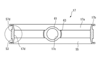
- the seat ring 17 includes a ring body 17a having a substantially cylindrical shape extending in the central axis direction, and a flange portion 17b extending outward from both ends of the ring body 17a in the center axis direction facing each other.
- the ring main body 17a has an outer peripheral surface 53 and an inner peripheral surface 55, and the valve shaft 15 is penetrated at a position of the ring main body 17a facing the rotation axis R direction.
- Two through holes 17c and 17c are formed so as to penetrate from the outer peripheral surface 53 to the inner peripheral surface 55.
- annular projection 57 that protrudes from the outer peripheral surface 53 and extends in an annular direction in the circumferential direction of the outer peripheral surface 53 is provided.
- the inner peripheral surface of the through hole 17c of the seat ring 17 shown in FIG. 6 is formed by a flat circumferential surface, but a plurality of annular ribs are provided on the inner peripheral surface of the through hole 17c to provide a through hole.
- the sealing property between the outer peripheral surface of the valve shaft 15 inserted through the 17c and the inner peripheral surface of the through hole 17c may be enhanced.
- the annular protrusion 57 is fitted into an annular fitting groove provided on the inner peripheral surface of the internal flow path 13a of the valve body 13, which will be described later, and functions to prevent the seat ring 17 from moving in the flow path axial direction. ..
- the annular protrusion 57 includes two through-hole protrusions 57a and 57a provided on the peripheral edge (periphery) surrounding the openings of the two through-holes 17c and 17c on the outer peripheral surface 53, and two through-hole protrusions. It includes two outer peripheral protrusions 57b and 57b extending in an arc shape in the circumferential direction of the ring body 17a so as to connect between 57a and 57a.
- the outer peripheral protrusion 57b has a rectangular cross section, and its top surface is flat in the width direction (the direction of the central axis of the ring body 17a) (that is, at the same height from the outer peripheral surface 53) and arcuate in the circumferential direction. Extends to.
- a planar protrusion sealing surface 59 located in the same plane is formed on the top of the through-hole protrusion 57a, and the protrusion sealing surface 59 is connected to the top surface of the outer peripheral protrusion 57b which is flat in the width direction. Has been done.
- a peripheral edge portion (opening to the internal flow path 13a side) surrounding each opening of the two through holes 17c and 17c (opening to the internal flow path 13a side) is formed.
- the two annular through-hole sealing surfaces 61 and 61 extending from the periphery
- the valve seat surface 17d extending in an arc shape in the circumferential direction of the inner peripheral surface 55 so as to connect between the two through-hole sealing surfaces 61 and 61.
- An inner peripheral transition surface 63 connecting between the through hole sealing surface 61 and the valve seat surface 17d is formed.
- the annular through-hole sealing surface 61 is formed in a planar shape so as to be located in the same plane, and has a protrusion sealing surface 59 formed on the peripheral edge of the opening of the through-hole 17c on the outer peripheral surface 53. It extends in parallel.
- the thickness from the through hole sealing surface 61 to the protrusion sealing surface 59 is equal to the thickness from the valve seat surface 17d of the inner peripheral surface 55 of the seat ring 17 to the top surface of the outer peripheral protrusion 57b of the outer peripheral surface 53. It has been decided.
- the thickness from the through hole sealing surface 61 to the protrusion sealing surface 59 is equal to the thickness from the valve seat surface 17d to the top surface of the outer peripheral protrusion 57b on the outside of the valve body 19 when the valve is closed. This is to make the crushing allowance of the seat ring 17 by the raised portion on the peripheral surface 45 uniform, and the thickness from the valve seat surface 17d to the top surface of the outer peripheral protrusion 57b is the thickness of the valve seat surface 17d and the outer peripheral protrusion 57b. Measured at the shortest distance. As shown in FIGS.
- the valve seat surface 17d has a concave shape that forms a part of a spherical surface centered on the center (center in the diameter direction and the width direction) of the ring body 17a.
- the inner peripheral transition surface 63 is provided at a position where it comes into contact with the outer peripheral transition surface 51 when the valve is closed, has a predetermined width, and extends in an arc shape so as to be coaxial with the through hole 17c. ing.
- the annular protrusion 57 on the outer peripheral surface 53 side of the seat ring 17 is located so as to face the valve seat surface 17d provided on the inner peripheral surface 55 in the radial direction of the ring body 17a, and the opening ridge of the valve body 19 is raised when the valve is closed.
- the through hole seal surface 61 of the seat ring 17 and the protrusion The portion between the portion sealing surface 59 and the valve seat surface 17d and the top surface of the outer peripheral protrusion 57b is elastically compressed, and between the outer peripheral edge portion of the valve body 19 and the inner peripheral surface 55 of the seat ring 17.
- the through-hole protrusion has a larger amount of protrusion from the outer peripheral surface and is thicker than the outer peripheral protrusion of the annular protrusion.
- the crushing allowance of the seat ring at the time of valve closing is different from the portion where the portion is provided, the crushing rate changes depending on the portion in the circumferential direction of the seat ring, and the sealing property becomes non-uniform.
- the thickness from the through hole sealing surface 61 to the protrusion sealing surface 59 of the through hole protrusion 57a is from the valve seat surface 17d of the ring body 17a of the seat ring 17 to the top surface of the outer peripheral protrusion 57b.
- the crushing allowance at the time of valve closing becomes equal between the portion provided with the outer peripheral protrusion 57b and the portion provided with the through-hole protrusion 57a, and the seat ring 17 is formed in the circumferential direction.
- the crushing rate does not change depending on the part. Therefore, the butterfly valve 11 has the effect that the sealing property between the outer peripheral edge portion of the valve body 19 and the inner peripheral surface 55 of the seat ring 17 becomes uniform in the circumferential direction regardless of the portion.
- the position is such that the inner peripheral transition surface 63 on the inner peripheral surface 55 of the seat ring 17 comes into contact with the outer peripheral transition surface 51 of the raised portion on the outer peripheral surface 45 of the valve body 19 when the valve is closed. It is provided. Further, the outer peripheral transition surface 51 has the same width as the peripheral seal surface 49a, the contact width with the inner peripheral transition surface 63 is reduced, and the inner peripheral transition surface 63 has a through hole 17c. It extends in an arc shape so as to be coaxial. The outer peripheral transition surface 51 provided on the raised portion of the valve body 19 rotates around the rotation axis R as the valve body 19 rotates.
- the valve when the width of the outer peripheral transition surface 51 is wide and the valve seat surface 17d has a cylindrical shape rather than a concave shape forming a part of a spherical surface, the valve is closed.
- the outer peripheral transition surface 51 and the inner peripheral transition surface 63 have a positional relationship of intersecting each other until immediately before.
- the crushing rate tends to be non-uniform until the valve is closed.
- the rotation angle of the valve body 19 when the valve is closed is slightly deviated, the crushing rate in the vicinity of the inner peripheral transition surface 63 becomes non-uniform.
- the width of the outer peripheral transition surface 51 is narrowed, and the inner peripheral transition surface 63 extends in an arc shape so as to be coaxial with the through hole 17c. Therefore, in the process of rotating the valve body 19 to the closed valve state, the outer peripheral transition surface 51 moves along the inner peripheral transition surface 63, and as a result, the crushing rate is less likely to become non-uniform.
- the width of the outer peripheral protrusion 57b of the annular protrusion 57 (the length of the ring body 17a in the central axis direction) is further as shown in FIGS. 9 and 10 for the valve seat. It is set to be wider than the width of the surface 17d. If the width of the valve seat surface 17d is wider than the width of the outer peripheral protrusion 57b, the peripheral edge sealing surface 49a of the peripheral edge raised portion 49 of the outer peripheral edge surface 45 of the valve body 19 begins to come into contact with the valve seat surface 17d.
- the outer peripheral protrusion 57b of the annular protrusion 57 is located between the inner peripheral surface of the internal flow path 13a of the valve body 13 to which the seat ring 17 is mounted and the contact portion between the peripheral seal surface 49a and the valve seat surface 17d.
- the valve body 13 has a substantially cylindrical shape in which an internal flow path 13a is formed in the central portion.
- a first bearing hole 25 and a second bearing hole 27 extending so as to face each other in the radial direction (vertical direction in FIG. 12) of the internal flow path 13a are formed.
- a top flange 23 is provided on the upper portion of the valve body 13, and a first bearing hole 25 penetrates the top flange 23 and extends to the outside. The lower end of the second bearing hole 27 is closed by the valve shaft holder 29.
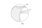
- annular fitting groove 65 into which the annular projection 57 of the seat ring 17 is fitted is provided on the inner peripheral surface of the internal flow path 13a of the valve body 13.
- the annular fitting groove 65 has a shape complementary to the annular protrusion 57 of the seat ring 17.
- the annular fitting groove 65 includes an opening groove portion 65a having a flat groove bottom surface formed around the openings of the first bearing hole 25 and the second bearing hole 27 to the internal flow path 13a.
- the peripheral groove portion 65b has a substantially rectangular cross section having a shape complementary to the outer peripheral protrusion portion 57b.
- the outer peripheral portion of the valve body 13 is stealed for weight reduction.
- meat stealing is not performed, and the wall is formed thicker than the remaining portion.
- the valve body 19 is pushed into the internal flow path 13a (specifically, the inside of the seat ring 17 mounted on the inner peripheral surface of the internal flow path 13a)
- the valve body 13 extends in the rotation axis R direction.
- the region where meat stealing is not performed is preferably a region located within a range of 40 ° or more and 60 ° or less around the center of the internal flow path 13a from the rotation axis R on both sides of the rotation axis R.
- one of the two peripheral groove portions 65b and 65b is located on the downstream side of the internal flow path 13a at the upper edge end portion of the peripheral edge groove portion 65b (in the internal flow path 13a, on the downstream side of the peripheral edge groove portion 65b).
- a chamfered surface 67 is provided on the peripheral edge portion 65b of the inner peripheral surface to be located), and the other of the two peripheral groove portions 65b and 65b is located on the upstream side of the internal flow path 13a.
- a chamfered surface 67 is provided at the upper edge end portion.
- a space is formed between the peripheral surface and the outer peripheral surface of the seat ring 17, and serves as an escape allowance for deformation of the seat ring 17. Therefore, by providing the chamfered surface 67 on the side where the outer peripheral edge portion of the valve body 19 is rotated around the rotation axis R and enters the valve seat surface 17d of the seat ring 17 when the valve is changed from the valve open state to the valve closed state. It is possible to provide an escape space for deformation of the seat ring 17 when the peripheral edge sealing surface 49a of the peripheral edge raised portion 49 of the valve body 19 begins to abut on the valve seat surface 17d (that is, when seated).
- the chamfered surface 67 is preferably formed by an inclined surface. Further, the angle formed by the inclined surface and the extension surface of the side surface of the peripheral groove portion 65b is the peripheral raised portion 49 of the valve body 19 when the rotation angle of the valve body 19 when the butterfly valve is fully open is 0 °. It is more preferable that the peripheral sealing surface 49a and the chamfered surface 67, which is an inclined surface, are set to match the rotation angle of the valve body 19 when they come into contact with each other. For example, the angle between the inclined surface and the extension surface of the side surface of the peripheral groove portion 65b may be 80 ° to 85 °.
- the chamfered surface 67 may be provided at the upper edge ends on both sides of the peripheral groove portion 65b of the annular fitting groove 65. However, in order not to reduce the effect of preventing the annular projection 57 of the seat ring 17 from moving in the flow path axial direction with respect to the annular fitting groove 65, the chamfered surface 67 is provided only on one side of the peripheral groove portion 65b. Is preferable.
- FIG. 15 shows the angle of the chamfered surface 49b of the peripheral edge portion 49 of the outer peripheral surface 45 of the valve body 19 in the butterfly valve 11 according to the present invention, which was obtained by simulation by changing the friction coefficient between the valve body 19 and the seat ring 17. It is a line graph which shows the relationship with the operation torque of a valve shaft 15. The simulation is provided until the width of the peripheral sealing surface 49a of the peripheral raised portion 49 is 4 mm, the chamfered surface 49b is separated from the peripheral sealing surface 49a by a length of 3 mm in the vertical direction, and the peripheral raised portion 49 is the valve seat surface of the seat ring 17.
- the operating torque of 19 was obtained.
- the seat ring 17 was formed of EPDM and the valve body 19 was formed of PP.
- the simulation was performed when the friction coefficient between the valve body 19 and the seat ring 17 was 0.1 and 0.2. When the friction coefficient was 0.1, the simulation was performed even under the condition that the amount of the peripheral raised portion 49 crushing the valve seat surface 17d of the seat ring 17 was 2.5 mm.
- the operating torque can be kept low in the range of the angle of the chamfered surface 49b from 15 ° to 30 ° regardless of the conditions of the friction coefficient and the condition of the crushing amount. Therefore, in the butterfly valve 11, it is preferable to set the angle of the chamfered surface 49b in the range of 15 ° to 30 °.
- valve body 19 is rotatably supported on the valve body 13 by two valve shafts 15a and 15b, but the valve body 19 is supported on the valve body 13 by one valve shaft 15. May be supported.
- Valve body 13a Internal flow path 15 Valve shaft 15a First valve shaft 15b Second valve shaft 19 Valve body 45 Outer peripheral surface 47 Opening ridge 47a Open seal surface 47b Chamfer surface 49 Peripheral ridge 49a Peripheral seal Surface 49b Chamfered surface 51 Outer peripheral transition surface 53 Outer peripheral surface 55 Inner peripheral surface 57 Circular protrusion 57a Through hole protrusion 57b Outer peripheral protrusion 59 Projection sealing surface 61 Through hole sealing surface 63 Inner peripheral transition surface 65 Fitting groove 65a Opening groove 65b Peripheral groove 67 Chamfered surface
Landscapes
- Engineering & Computer Science (AREA)
- General Engineering & Computer Science (AREA)
- Mechanical Engineering (AREA)
- Lift Valve (AREA)
Abstract
Description
13 弁本体
13a 内部流路
15 弁軸
15a 第1の弁軸
15b 第2の弁軸
19 弁体
45 外周縁面
47 開口隆起部
47a 開口シール面
47b 面取り面
49 周縁隆起部
49a 周縁シール面
49b 面取り面
51 外周遷移面
53 外周面
55 内周面
57 環状突起
57a 貫通孔突起部
57b 外周突起部
59 突起部シール面
61 貫通孔シール面
63 内周遷移面
65 嵌合溝
65a 開口溝部
65b 周縁溝部
67 面取り面
Claims (12)
- 流路軸線方向に延びる内部流路が形成されている弁本体と、前記内部流路の内周面に装着されるシートリングと、回転軸線周りに回転可能に前記弁本体に支持された弁軸と、前記弁軸に接続されて弁本体に回転可能に支持され且つ前記シートリング内に配置される概略円盤形状の弁体とを備え、前記回転軸線周りに前記弁体を回転させて前記弁体の該周縁部を前記シートリングの内周面に接離させることによって、前記内部流路の開閉を行うバタフライバルブであって、
前記弁体が周方向に延びる環状の外周縁面を有し、該外周縁面上における前記回転軸線方向の対向する位置に前記弁軸を挿通させるための二つの弁軸開口部が形成されており、前記弁体の前記外周縁面には、前記外周縁面から突出して各弁軸開口部の周縁部に沿って延びる環状の二つ開口隆起部と、前記外周縁面から突出して前記二つの開口隆起部の間を接続するように前記弁体の周方向に延びる周縁隆起部とがさらに設けられており、前記周縁隆起部が、その頂部に沿って周方向に円弧状に且つ幅方向に平坦に延びる周縁シール面と、該周縁シール面に対して前記弁体の前記外周縁面へ向かって予め定められた角度をなして傾斜し且つ前記周縁シール面の両側に沿って延びる面取り面とを有していることを特徴とするバタフライバルブ。 - 前記予め定められた角度が15°から30°の範囲の角度である、請求項1に記載のバタフライバルブ。
- 前記周縁シール面の幅が3mmから10mmの範囲である、請求項1又は請求項2に記載のバタフライバルブ。
- 前記シートリングは、外周面及び内周面と、前記外周面から突出して環状に延びる環状突起とを備えており、前記弁本体の内部流路の内周面に前記シートリングの前記環状突起と嵌合する環状嵌合溝が設けられている、請求項1から請求項3の何れか一項に記載のバタフライバルブ。
- 前記環状嵌合溝における前記回転軸線方向の対向する位置に前記弁軸を挿通して支持するための二つの軸受孔が開口しており、前記環状嵌合溝が、前記二つの軸受孔の開口部の周縁部に設けられた二つの開口溝部と、該二つの開口溝部の間を接続するように周方向に延びる二つの周縁溝部とを含み、該二つの周縁溝部の一方が下流側の上縁端部に面取り部を設けられていると共に、該二つの周縁溝の他方が上流側の上端端部に面取り部を設けられている、請求項4に記載のバタフライバルブ。
- 前記環状嵌合溝の前記周縁溝部が矩形状断面を有し、前記面取り部が傾斜面によって形成されており、前記傾斜面と前記周縁溝部の側面の延長面とがなす角度は、前記バタフライバルブの全開状態のときの前記弁体の回転角度を0°としたときに、前記弁体の前記周縁隆起部の前記周縁シール面と前記傾斜面とが接触するときの前記弁体の回転角度と一致するように定められている、請求項5に記載のバタフライバルブ。
- 前記シートリングに、前記弁軸を貫通させるために前記外周面から前記内周面まで貫通して延びる二つの貫通孔が回転軸線方向に対向する位置に形成されており、前記シートリングの内周面上には、各貫通孔の周縁部に平面状に延びる環状の二つの貫通孔シール面と、該二つの貫通孔シール面の間を接続するように周方向に円弧状に延びる弁座面と、前記貫通孔シール面と前記弁座面との間を接続する内周遷移面とが形成され、前記弁体の外周面には、前記開口隆起部の頂部に延びる環状の開口シール面と、該開口シール面と前記周縁シール面との間を接続する外周遷移面とがさらに形成されており、前記内周遷移面が前記貫通孔と同軸となるように円弧状に延びていると共に、閉弁時において前記内周遷移面が前記外周遷移面と接触するようになっている、請求項4に記載のバタフライバルブ。
- 前記シートリングの前記内周面上に形成される前記弁座面は、球面の一部をなす凹形状を有している、請求項7に記載のバタフライバルブ。
- 前記環状突起が、前記シートリングの前記外周面上で各貫通孔の周縁部に設けられた環状の二つの貫通孔突起部と、該二つの貫通孔突起部の間を接続するように周方向に延びる二つの外周突起部とを含み、各貫通孔突起部の頂部に、前記貫通孔シール面と平行に延びる突起部シール面が形成されており、前記貫通孔シール面から前記突起部シール面までの厚さが前記シートリングの前記弁座面から前記外周突起部の頂部までの厚さと等しくなっている、請求項7に記載のバタフライバルブ。
- 前記シートリングに、前記弁軸を貫通させるために前記外周面から前記内周面まで貫通して延びる二つの貫通孔が回転軸線方向に対向する位置に形成されており、前記シートリングの内周面上には、各貫通孔の周縁部に平面状に延びる環状の二つの貫通孔シール面と、該二つの貫通孔シール面の間を接続するように周方向に円弧状に延びる弁座面とが形成され、前記環状突起の幅が前記弁座面の幅よりも大きくなっている、請求項4に記載のバタフライバルブ。
- 前記弁本体は、前記回転軸線の両側に前記回転軸線から前記内部流路の中心周りの予め定められた角度の範囲内に位置する前記軸受孔に隣接する領域以外の外周部に肉盗みを施されている、請求項1から請求項10の何れか一項に記載のバタフライバルブ。
- 前記予め定められた角度は、40°以上60°以下である、請求項11に記載のバタフライバルブ。
Priority Applications (5)
| Application Number | Priority Date | Filing Date | Title |
|---|---|---|---|
| EP21851565.8A EP4191101B1 (en) | 2020-07-31 | 2021-07-29 | Butterfly valve |
| US18/018,767 US12140230B2 (en) | 2020-07-31 | 2021-07-29 | Butterfly valve |
| JP2022539553A JP7737377B2 (ja) | 2020-07-31 | 2021-07-29 | バタフライバルブ |
| CN202180058546.0A CN116057306A (zh) | 2020-07-31 | 2021-07-29 | 蝶形阀 |
| KR1020237004360A KR102932922B1 (ko) | 2020-07-31 | 2021-07-29 | 버터플라이 밸브 |
Applications Claiming Priority (2)
| Application Number | Priority Date | Filing Date | Title |
|---|---|---|---|
| JP2020-131218 | 2020-07-31 | ||
| JP2020131218 | 2020-07-31 |
Publications (1)
| Publication Number | Publication Date |
|---|---|
| WO2022025169A1 true WO2022025169A1 (ja) | 2022-02-03 |
Family
ID=80036268
Family Applications (1)
| Application Number | Title | Priority Date | Filing Date |
|---|---|---|---|
| PCT/JP2021/028059 Ceased WO2022025169A1 (ja) | 2020-07-31 | 2021-07-29 | バタフライバルブ |
Country Status (7)
| Country | Link |
|---|---|
| US (1) | US12140230B2 (ja) |
| EP (1) | EP4191101B1 (ja) |
| JP (1) | JP7737377B2 (ja) |
| KR (1) | KR102932922B1 (ja) |
| CN (1) | CN116057306A (ja) |
| TW (1) | TWI877382B (ja) |
| WO (1) | WO2022025169A1 (ja) |
Families Citing this family (1)
| Publication number | Priority date | Publication date | Assignee | Title |
|---|---|---|---|---|
| JP1679877S (ja) * | 2020-07-17 | 2021-02-22 |
Citations (6)
| Publication number | Priority date | Publication date | Assignee | Title |
|---|---|---|---|---|
| JPS4914821B1 (ja) * | 1969-11-24 | 1974-04-10 | ||
| JP2004183711A (ja) | 2002-11-29 | 2004-07-02 | Asahi Organic Chem Ind Co Ltd | バタフライバルブ用シートリング |
| JP2005233294A (ja) | 2004-02-19 | 2005-09-02 | Tomoe Tech Res Co | 中心形バタフライ弁用弁体の製造方法 |
| WO2015147197A1 (ja) * | 2014-03-28 | 2015-10-01 | 株式会社キッツ | バタフライバルブのシール構造 |
| JP2016041967A (ja) * | 2014-08-19 | 2016-03-31 | 株式会社キッツ | バタフライバルブの弁体及びバタフライバルブ |
| WO2021132712A1 (ja) * | 2019-12-27 | 2021-07-01 | 株式会社キッツ | ライニング型バタフライバルブとライニング型バタフライバルブの製造方法 |
Family Cites Families (10)
| Publication number | Priority date | Publication date | Assignee | Title |
|---|---|---|---|---|
| US4133513A (en) * | 1976-10-26 | 1979-01-09 | Celanese Corporation | Butterfly valve assembly |
| US4491300A (en) * | 1981-11-27 | 1985-01-01 | Amsted Industries Incorporated | Valve with improved sealing structure |
| JP3045671B2 (ja) * | 1996-08-30 | 2000-05-29 | 株式会社巴技術研究所 | バタフライ弁のシートリング |
| CN103322212B (zh) * | 2013-07-01 | 2015-10-14 | 德尔斯威(厦门)流体控制设备有限公司 | 浮动式阀座热力蝶阀 |
| US9695947B2 (en) * | 2013-07-30 | 2017-07-04 | Hayward Industries, Inc. | Handle insert for valve |
| US9903496B2 (en) * | 2015-05-29 | 2018-02-27 | Mueller International, Llc | Lining for mechanical joints |
| JP6715692B2 (ja) * | 2016-06-17 | 2020-07-01 | 旭有機材株式会社 | バタフライバルブ用のシートリング及びこれを備えるバタフライバルブ |
| JP6755140B2 (ja) * | 2016-07-20 | 2020-09-16 | 旭有機材株式会社 | バタフライ弁 |
| TWI677638B (zh) * | 2018-09-04 | 2019-11-21 | 和正豐科技股份有限公司 | 氟塑料蝶閥構造 |
| JP7350780B2 (ja) * | 2018-12-28 | 2023-09-26 | 株式会社キッツ | 中心型バタフライバルブ |
-
2021
- 2021-06-24 TW TW110123148A patent/TWI877382B/zh active
- 2021-07-29 CN CN202180058546.0A patent/CN116057306A/zh active Pending
- 2021-07-29 JP JP2022539553A patent/JP7737377B2/ja active Active
- 2021-07-29 EP EP21851565.8A patent/EP4191101B1/en active Active
- 2021-07-29 WO PCT/JP2021/028059 patent/WO2022025169A1/ja not_active Ceased
- 2021-07-29 KR KR1020237004360A patent/KR102932922B1/ko active Active
- 2021-07-29 US US18/018,767 patent/US12140230B2/en active Active
Patent Citations (6)
| Publication number | Priority date | Publication date | Assignee | Title |
|---|---|---|---|---|
| JPS4914821B1 (ja) * | 1969-11-24 | 1974-04-10 | ||
| JP2004183711A (ja) | 2002-11-29 | 2004-07-02 | Asahi Organic Chem Ind Co Ltd | バタフライバルブ用シートリング |
| JP2005233294A (ja) | 2004-02-19 | 2005-09-02 | Tomoe Tech Res Co | 中心形バタフライ弁用弁体の製造方法 |
| WO2015147197A1 (ja) * | 2014-03-28 | 2015-10-01 | 株式会社キッツ | バタフライバルブのシール構造 |
| JP2016041967A (ja) * | 2014-08-19 | 2016-03-31 | 株式会社キッツ | バタフライバルブの弁体及びバタフライバルブ |
| WO2021132712A1 (ja) * | 2019-12-27 | 2021-07-01 | 株式会社キッツ | ライニング型バタフライバルブとライニング型バタフライバルブの製造方法 |
Non-Patent Citations (1)
| Title |
|---|
| See also references of EP4191101A4 |
Also Published As
| Publication number | Publication date |
|---|---|
| US12140230B2 (en) | 2024-11-12 |
| EP4191101A1 (en) | 2023-06-07 |
| KR20230042474A (ko) | 2023-03-28 |
| EP4191101B1 (en) | 2025-11-19 |
| JPWO2022025169A1 (ja) | 2022-02-03 |
| KR102932922B1 (ko) | 2026-03-03 |
| EP4191101A4 (en) | 2024-11-27 |
| JP7737377B2 (ja) | 2025-09-10 |
| TW202206727A (zh) | 2022-02-16 |
| US20230304584A1 (en) | 2023-09-28 |
| TWI877382B (zh) | 2025-03-21 |
| CN116057306A (zh) | 2023-05-02 |
Similar Documents
| Publication | Publication Date | Title |
|---|---|---|
| JP6715692B2 (ja) | バタフライバルブ用のシートリング及びこれを備えるバタフライバルブ | |
| TWI782167B (zh) | 偏心型蝶形閥 | |
| JP7778697B2 (ja) | バタフライバルブ | |
| TWI794389B (zh) | 蝶形閥 | |
| KR20090118039A (ko) | 튜브 단부 버터플라이 계량 및 차단 밸브 | |
| JP2006283873A (ja) | バタフライバルブ | |
| SK286206B6 (sk) | Guľový ventil | |
| WO2022025169A1 (ja) | バタフライバルブ | |
| TW200413658A (en) | Seat ring for butterfly valve | |
| US10267424B2 (en) | Butterfly valve seat with seat cover | |
| JP7737378B2 (ja) | バタフライバルブ | |
| JP6600535B2 (ja) | ライニング型バタフライバルブ | |
| JP2016070473A (ja) | バタフライ弁用のシートリング及バタフライ弁 |
Legal Events
| Date | Code | Title | Description |
|---|---|---|---|
| 121 | Ep: the epo has been informed by wipo that ep was designated in this application |
Ref document number: 21851565 Country of ref document: EP Kind code of ref document: A1 |
|
| ENP | Entry into the national phase |
Ref document number: 2022539553 Country of ref document: JP Kind code of ref document: A |
|
| ENP | Entry into the national phase |
Ref document number: 20237004360 Country of ref document: KR Kind code of ref document: A |
|
| WWE | Wipo information: entry into national phase |
Ref document number: 2021851565 Country of ref document: EP |
|
| ENP | Entry into the national phase |
Ref document number: 2021851565 Country of ref document: EP Effective date: 20230228 |
|
| NENP | Non-entry into the national phase |
Ref country code: DE |
|
| WWG | Wipo information: grant in national office |
Ref document number: 2021851565 Country of ref document: EP |