WO2022030058A1 - 通信装置、通信装置の制御方法、及び、プログラム - Google Patents
通信装置、通信装置の制御方法、及び、プログラム Download PDFInfo
- Publication number
- WO2022030058A1 WO2022030058A1 PCT/JP2021/017612 JP2021017612W WO2022030058A1 WO 2022030058 A1 WO2022030058 A1 WO 2022030058A1 JP 2021017612 W JP2021017612 W JP 2021017612W WO 2022030058 A1 WO2022030058 A1 WO 2022030058A1
- Authority
- WO
- WIPO (PCT)
- Prior art keywords
- communication
- communication device
- frequency bands
- mode
- frequency
- Prior art date
- Legal status (The legal status is an assumption and is not a legal conclusion. Google has not performed a legal analysis and makes no representation as to the accuracy of the status listed.)
- Ceased
Links
Images






Classifications
-
- H—ELECTRICITY
- H04—ELECTRIC COMMUNICATION TECHNIQUE
- H04W—WIRELESS COMMUNICATION NETWORKS
- H04W48/00—Access restriction; Network selection; Access point selection
- H04W48/08—Access restriction or access information delivery, e.g. discovery data delivery
-
- H—ELECTRICITY
- H04—ELECTRIC COMMUNICATION TECHNIQUE
- H04L—TRANSMISSION OF DIGITAL INFORMATION, e.g. TELEGRAPHIC COMMUNICATION
- H04L5/00—Arrangements affording multiple use of the transmission path
- H04L5/003—Arrangements for allocating sub-channels of the transmission path
- H04L5/0037—Inter-user or inter-terminal allocation
- H04L5/0041—Frequency-non-contiguous
-
- H—ELECTRICITY
- H04—ELECTRIC COMMUNICATION TECHNIQUE
- H04L—TRANSMISSION OF DIGITAL INFORMATION, e.g. TELEGRAPHIC COMMUNICATION
- H04L5/00—Arrangements affording multiple use of the transmission path
- H04L5/0001—Arrangements for dividing the transmission path
- H04L5/0028—Variable division
-
- H—ELECTRICITY
- H04—ELECTRIC COMMUNICATION TECHNIQUE
- H04L—TRANSMISSION OF DIGITAL INFORMATION, e.g. TELEGRAPHIC COMMUNICATION
- H04L5/00—Arrangements affording multiple use of the transmission path
- H04L5/003—Arrangements for allocating sub-channels of the transmission path
- H04L5/0058—Allocation criteria
-
- H—ELECTRICITY
- H04—ELECTRIC COMMUNICATION TECHNIQUE
- H04W—WIRELESS COMMUNICATION NETWORKS
- H04W48/00—Access restriction; Network selection; Access point selection
- H04W48/16—Discovering, processing access restriction or access information
-
- H—ELECTRICITY
- H04—ELECTRIC COMMUNICATION TECHNIQUE
- H04W—WIRELESS COMMUNICATION NETWORKS
- H04W76/00—Connection management
- H04W76/10—Connection setup
- H04W76/15—Setup of multiple wireless link connections
-
- H—ELECTRICITY
- H04—ELECTRIC COMMUNICATION TECHNIQUE
- H04W—WIRELESS COMMUNICATION NETWORKS
- H04W76/00—Connection management
- H04W76/20—Manipulation of established connections
-
- H—ELECTRICITY
- H04—ELECTRIC COMMUNICATION TECHNIQUE
- H04W—WIRELESS COMMUNICATION NETWORKS
- H04W84/00—Network topologies
- H04W84/02—Hierarchically pre-organised networks, e.g. paging networks, cellular networks, WLAN [Wireless Local Area Network] or WLL [Wireless Local Loop]
- H04W84/10—Small scale networks; Flat hierarchical networks
- H04W84/12—WLAN [Wireless Local Area Networks]
-
- H—ELECTRICITY
- H04—ELECTRIC COMMUNICATION TECHNIQUE
- H04W—WIRELESS COMMUNICATION NETWORKS
- H04W72/00—Local resource management
- H04W72/04—Wireless resource allocation
- H04W72/044—Wireless resource allocation based on the type of the allocated resource
- H04W72/0453—Resources in frequency domain, e.g. a carrier in FDMA
-
- H—ELECTRICITY
- H04—ELECTRIC COMMUNICATION TECHNIQUE
- H04W—WIRELESS COMMUNICATION NETWORKS
- H04W88/00—Devices specially adapted for wireless communication networks, e.g. terminals, base stations or access point devices
- H04W88/02—Terminal devices
- H04W88/06—Terminal devices adapted for operation in multiple networks or having at least two operational modes, e.g. multi-mode terminals
Definitions
- the present invention relates to wireless communication technology.
- WLAN wireless local area network
- IEEE802.11 IEEE802.11n / a / b / g / ac or IEEE802.11ax
- Patent Document 1 IEEE802.11n / a / b / g / ac
- OFDMA Orthogonal Frequency Division Multiplexing Access
- IEEE802.11be a tax group called IEEE802.11be has been launched as a successor standard aimed at further improving throughput, improving frequency utilization efficiency, and improving communication latency.
- IEEE802.11be a multi-link technology for transmitting to a single STA (station / terminal device) by simultaneously using a plurality of frequency bands (radio channels) in the 2.4 GHz, 5 GHz, and 6 GHz bands is being studied.
- an STA conforming to the 802.11 standard has been connected to an AP (access point) and performed data communication with the access point in a single frequency band.
- throughput can be improved by simultaneously performing data communication between AP and STA on two or more wireless channels.
- Multi-link communication has multiple communication modes. For example, there are an asynchronous mode in which AP and STA independently transmit and receive in a plurality of frequency bands, and a synchronous mode in which transmission and reception are performed while synchronizing in a plurality of frequency bands. In addition, there is also a quasi-asynchronous mode (Semi-Asynchronous mode) in which a synchronous mode and an asynchronous mode are used properly depending on the situation.
- asynchronous mode in which AP and STA independently transmit and receive in a plurality of frequency bands
- a synchronous mode in which transmission and reception are performed while synchronizing in a plurality of frequency bands.
- Semi-Asynchronous mode quasi-asynchronous mode in which a synchronous mode and an asynchronous mode are used properly depending on the situation.
- the asynchronous mode is a mode in which AP and STA perform transmission and reception independently in each frequency band used, and each device (AP, STA) may perform transmission and reception at the same time.
- each device AP, STA
- the transmission signal will be mixed into the reception circuit as an interference wave, causing internal interference that adversely affects the reception characteristics. Can occur. Therefore, in the asynchronous mode, a frequency band with a small interval that causes interference in the device cannot be used.
- the synchronous mode is a mode in which AP and STA simultaneously transmit or receive in each frequency band to be used. Therefore, it is possible to use a frequency band having a small interval that causes interference in the device.
- ML-STA the STA corresponding to the multi-link technology
- NonML-STA the STA not compatible with the multi-link technology
- the throughput can be improved by multi-link communication, but if the AP and ML-STA are not communicating in an appropriate communication mode, the throughput may decrease.
- the AP and the ML-STA are performing multi-link communication in the synchronous mode using a plurality of frequency bands having a small interval so as to cause interference in the device.
- ML-STA and AP need to perform communication in consideration of in-device interference in another frequency band.
- AP and ML-STA are in a state of multi-link communication in synchronous mode and used in an application that transmits and receives data in both directions in real time, transmission and reception cannot be performed at the same time. Therefore, it may affect the use of the application.
- Various embodiments of the present disclosure provide techniques for determining a frequency band to be appropriately used in multilink communication.
- the communication device of the present invention has the following configuration. That is, It is a communication device that conforms to the IEEE802.11 series standard.
- a communication means that communicates in either a first mode in which transmission and reception are performed independently in each frequency band, or a second mode in which transmission or reception is performed simultaneously in each frequency band.
- a determination means for determining whether or not a predetermined condition for changing the communication mode is satisfied, It has a determination means for determining one or more frequency bands to be used for communication in the changed communication mode when it is determined by the determination means that the predetermined condition is satisfied. While the communication means is communicating with the first other communication device using each frequency band of the plurality of frequency bands in the first mode or the second mode, the predetermined by the determination means.
- the determination means determines a plurality of frequency bands for communication in the changed communication mode based on the plurality of frequency bands, and the communication means determines the plurality of frequency bands.
- the determined frequency band is used to communicate with the first other communication device in the changed communication mode.
- FIG. 1 An example of network configuration is shown. It is a block diagram which shows the functional structure example of a communication apparatus (AP, ML-STA). It is a block diagram which shows the functional structure example of a communication apparatus (NonML-STA). It is a block diagram which shows the hardware configuration example of the communication apparatus (AP, ML-STA). It is a block diagram which shows the hardware configuration example of the communication apparatus (NonML-STA). It is a conceptual diagram for demonstrating the frequency interval value necessary for the occurrence of interference in equipment.
- connection process with ML-STA executed by AP in 1st Embodiment. It is a sequence chart diagram of the connection processing executed by AP and ML-STA in 1st Embodiment. It is a figure which shows the frequency interval of a link in 1st Embodiment. It is a flowchart of the connection process with NonML-STA executed by AP in 1st Embodiment. It is a sequence chart diagram of the connection process executed by AP and NonML-STA in 1st Embodiment. It is a conceptual diagram of the frequency band change of a link in 1st Embodiment.
- the frequency channel is defined by the standard of the IEEE802 series, and the channel numbers in the 2.4 GHz band, 5 GHz band, and 6 GHz band are not limited to those disclosed in the present specification. , Any number (channel) may be used.
- the link to be used is transmitted and received at the same time. It is an embodiment about the process of changing to a frequency band that can be executed.
- ML-STA is an STA (station / terminal device) compatible with the multi-link technology
- NonML-STA indicates an STA not compatible with the multi-link technology.
- the link refers to a frequency channel (frequency band) in which data can be transmitted and received.
- FIG. 1 shows an example of a network configuration according to the present embodiment.
- FIG. 1 shows a configuration including an AP (access point) 102, ML-STA103, and NonML-STA104 as a communication device corresponding to IEEE802.11be.
- AP102 is a communication device corresponding to the multi-link technology.
- the network formed by AP102 is represented by a circle 101.
- the ML-STA103 and NonML-STA104 can transmit and receive signals transmitted and received by the AP102.
- the AP102 and the ML-STA103 are provided with a plurality of wireless LAN control units, and can transmit and receive frames simultaneously using a plurality of frequency bands.
- the NonML-STA 104 is provided with one wireless LAN control unit and transmits / receives frames using one frequency band.
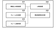
- FIG. 2A shows a block diagram of a functional configuration example of AP102 and ML-STA103.
- the AP102 and ML-STA103 have wireless LAN control units 201a, 201b, 201c, frame generation unit 202, frame analysis unit 203, UI (user interface) control unit 204, frequency band determination unit 205, and multilink, respectively, as examples of functional configurations.
- It includes a communication control unit 206 and a communication mode control unit 207.
- the wireless LAN control units 201a, 201b, and 201c are configured to include a program that controls for transmitting and receiving wireless signals to and from other wireless LAN devices.
- the wireless LAN control units 201a, 201b, and 201c execute wireless LAN communication control based on the frames generated by the frame generation unit 202 in accordance with the IEEE802.11 standard series.
- the wireless LAN control units 201a, 201b, and 201c communicate with each other in the 2.4 GHz band, 5 GHz band, or 6 GHz band via the antennas 306a, 306b, 306c (FIG. 3A), respectively (communication control). Shall be able to do.
- the number of wireless LAN control units is not limited to three, and may be two or four or more.
- the frame generation unit 202 generates a wireless control frame to be transmitted by the wireless LAN control units 201a, 201b, 201c.
- the contents of the radio control frame generated by the frame generation unit 202 may be restricted by the settings stored in the storage unit 301 (FIG. 3A). Further, the content of the wireless control frame may be changed by setting by the user via the input unit 304 (FIG. 3A) and the UI control unit 204.
- the frame analysis unit 203 interprets the frames received by the wireless LAN control units 201a, 201b, 201c, and reflects the contents in the wireless LAN control units 201a, 201b, 201c. Regardless of the frame received by any wireless LAN control unit, it is possible to control the wireless LAN control unit that has not received the frame by passing through the frame analysis unit 203 once.
- the UI control unit 204 includes a program that controls an operation of the AP102 and ML-STA103 for the input unit 304 (FIG. 3A) by a user (not shown). Further, the UI control unit 204 also has a function for presenting information such as display of an image or the like or voice output to the user via the output unit 305 (FIG. 3A).
- the frequency band determination unit 205 has a function for determining which frequency band is available for data communication.
- the multi-link communication control unit 206 has a function for controlling the multi-link communication. For example, the multi-link communication control unit 206 controls for determining (including changing or maintaining) a plurality of frequency bands to be used for communication.
- the communication mode control unit 207 controls the communication mode (synchronous mode, asynchronous mode, etc.). For example, the communication mode control unit 207 determines whether or not a predetermined condition for changing the communication mode is satisfied.
- the synchronous mode is a communication mode in which transmission / reception is performed while synchronizing in a plurality of frequency bands
- the asynchronous mode is a communication mode in which AP and STA independently transmit / receive in a plurality of frequency bands.
- FIG. 2B shows a block diagram of a functional configuration example of NonML-STA104.
- the wireless LAN control unit 211 includes a program that controls for transmitting and receiving wireless signals to and from other wireless LAN devices.
- the wireless LAN control unit 211 executes wireless LAN communication control based on the frame generated by the frame generation unit 212 in accordance with the IEEE802.11 standard series.
- the wireless LAN control unit 211 can perform communication (communication control) in any of the 2.4 GHz band, 5 GHz band, and 6 GHz band via the antenna 316 (FIG. 3B).
- the frame generation unit 212 generates a wireless control frame to be transmitted by the wireless LAN control unit 211.
- the contents of the wireless control frame generated by the frame generation unit 212 may be restricted by the settings stored in the storage unit 311 (FIG. 3B). Further, the content of the wireless control frame may be changed by a setting by the user via the UI control unit 214.
- the frame analysis unit 213 interprets the frame received by the wireless LAN control unit 211.
- the UI control unit 214 includes a program that controls an operation of the NonML-STA 104 on the input unit 314 (FIG. 3B) by a user (not shown). Further, the UI control unit 214 also has a function for presenting information such as display of an image or the like or voice output to the user via the output unit 315 (FIG. 3B).
- the frequency band determination unit 215 has a function for determining which frequency band can be used for data communication.
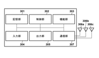
- FIG. 3A shows a block diagram of a hardware configuration example of AP102 and ML-STA103.
- AP102 will be described as an example, but the same description can be applied to ML-STA103.
- the AP 102 has a storage unit 301, a control unit 302, a function unit 303, an input unit 304, an output unit 305, a communication unit 307, and antennas 306a, 306b, and 306c as an example of the hardware configuration.
- the storage unit 301 is composed of ROM, RAM, or one of them, and stores various information such as a program for performing various operations described later and communication parameters for wireless communication.
- storage unit 301 in addition to memories such as ROM and RAM, storage media such as flexible disks, hard disks, optical disks, magneto-optical disks, CD-ROMs, CD-Rs, magnetic tapes, non-volatile memory cards, and DVDs. May be used.
- the control unit 302 is composed of, for example, a processor such as a CPU or MPU, an ASIC (integrated circuit for a specific application), a DSP (digital signal processor), an FPGA (field programmable gate array), or the like.
- CPU is an acronym for Central Processing Unit
- MPU is an acronym for Micro Processing Unit.
- the control unit 302 controls the entire AP 102 by executing the program stored in the storage unit 301.
- the control unit 302 may control the entire AP 102 in cooperation with the program stored in the storage unit 301 and the OS (Operating System).
- control unit 302 controls the function unit 303 to execute predetermined processing such as imaging, printing, and projection.
- the functional unit 303 is hardware for the AP 102 to execute a predetermined process.
- the functional unit 303 is an imaging unit and performs an imaging process.
- the functional unit 303 is a printing unit and performs printing processing.
- the functional unit 303 is a projection unit and performs projection processing.
- the data processed by the functional unit 303 may be data stored in the storage unit 301, or may be data communicated with another communication device via the communication unit 307 described later.
- the input unit 304 accepts various operations from the user.
- the output unit 305 outputs various outputs to the user.
- the output by the output unit 305 includes at least one such as a display on the screen, an audio output by the speaker, and a vibration output.
- both the input unit 304 and the output unit 305 may be realized by one module as in the touch panel.
- the input unit 304 and the output unit 305 may be integrated with the AP 102 or may be separate from each other.
- the communication unit 307 controls wireless communication and IP communication in accordance with the IEEE802.11 standard series. In the present embodiment, the communication unit 307 can execute processing conforming to at least the IEEE802.11be standard. Further, the communication unit 307 controls the antennas 306a, 306b, and 306c to transmit and receive wireless signals for wireless communication.
- the AP 102 communicates content such as image data, document data, and video data with another communication device via the communication unit 307. Further, the communication unit 307 includes a transmission queue for holding data to be transmitted.
- Antennas 306a, 306b, and 306c are antennas capable of communicating in at least one of the 2.4 GHz band, 5 GHz band, and 6 GHz band, respectively.
- the antennas 306a, 306b, and 306c are used for communication by the wireless LAN control units 201a, 201b, 201c (FIG. 2A), respectively.
- the antennas 306a, 306b, and 306c may be physically composed of one or more antennas in order to realize MIMO (Multi-Input and Multi-Output) transmission / reception.
- MIMO Multi-Input and Multi-Output
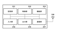
- FIG. 3B shows a block diagram of a hardware configuration example of NonML-STA104.
- the storage unit 311, the control unit 312, the functional unit 313, the input unit 314, the output unit 315, and the communication unit 317 are the storage unit 301, the control unit 302, the functional unit 303, the input unit 304, and the output unit of FIG. 3A. Since it is the same as 305 and the communication unit 317, the description thereof will be omitted. However, the communication unit 317 does not have to comply with the IEEE802.11be standard.
- the NonML-STA 104 has one antenna 316.
- the antenna 316 is an antenna capable of communicating in at least one of the 2.4 GHz band, the 5 GHz band, and the 6 GHz band. In this embodiment, the antenna 316 is used for communication by the wireless LAN control unit 211 (FIG. 2B).
- the antenna 316 may be physically composed of one or more antennas in order to realize MIMO transmission / reception.
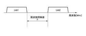
- FIG. 4 shows a conceptual diagram for explaining the frequency interval value F necessary for preventing the occurrence of interference in the device.
- the frequency interval value F is a frequency interval value required to prevent in-device interference when the two links (Link1 and Link2) are used.
- the frequency interval value F (hereinafter referred to as FAP) for AP102 is set to 200 MHz
- the frequency interval value F (hereinafter referred to as FML-STA) for ML- STA103 is set to 300 MHz.
- FIG. 5 shows a flowchart of the connection process with the ML-STA 103 executed by the AP 102 in the present embodiment
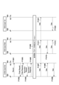
- FIG. 6 shows a sequence chart diagram of the connection process executed by the AP 102 and the ML-STA 103 in the present embodiment. show.
- the AP102 and the ML-STA103 have wireless LAN control units 201a, 201b, and 201c capable of communicating in any of the 2.4 GHz band, 5 GHz band, and 6 GHz band, respectively.
- the frequency at which the AP102 and the ML-STA103 communicate the management frame for connection processing is 2.4 GHz, and the connection in other frequency bands is also controlled by the communication. It should be noted that the use of 2.4 GHz is an example, and the frequency for transmitting and receiving the management frame is not limited to this.
- the management frame is defined in the standard of the IEEE802.11 series, and includes a Beacon frame, a Probe Request / Response, an Authentication Request / Response, an Authentication Request / Response, a Response Request / Response, and the like.
- the frame generation process is performed by the frame generation unit 202.
- the frequency band determination unit 205 of AP102 determines which frequency band can be used (S501). AP102 may make the determination depending on the degree of congestion in the surrounding wireless environment, but is not limited thereto. In the present embodiment, it is assumed that the 2.4 GHz band, the 5 GHz band, and the 6 GHz band can be used.
- the AP 102 transmits the frequency band information using one of the available frequency bands (S502).
- the frequency band information includes information on the frequency band available to the AP 102, information indicating that the AP 102 supports multi-link communication, and information on the F AP (the same applies to the following description).
- the wireless LAN control unit 201a of the AP102 adds frequency band information to the Beacon frame and transmits it in the 2.4 GHz band (F601). Note that the frequency band information may be added not only to the Beacon frame but also to the Probe Response, Authentication Response, Authentication Response, and Response Response frame transmitted by the AP102.
- the wireless LAN control unit 201a of the ML-STA 103 After the AP 102 transmits the frequency band information to the ML-STA 103, the wireless LAN control unit 201a of the ML-STA 103 that has received the Beacon frame transmits the Probe Request frame at 2.4 GHz and starts the scanning operation (F602).
- the wireless LAN control unit 201a of the ML-STA 103 may add frequency band information of the ML-STA 103 to the Probe Request frame.
- the frequency band information may include information on the frequency band in which the ML-STA 103 can be used, information indicating that the ML-STA 103 supports multi-link communication, and information on the F ML-STA (the following). The same applies to the explanation).
- the ML-STA 103 may include its available frequency information in the Authentication Request, Authentication Request, and Authentication Request frames and notify the AP 102.
- the wireless LAN control unit 201a of the AP102 Upon receiving the Probe Request frame from the ML-STA 103, the wireless LAN control unit 201a of the AP102 transmits the Probe Response frame to the ML-STA 103 (F603).
- the Probe Response frame may include available frequency information for the AP102.
- the frame analysis unit 203 of the ML-STA 103 uses the available frequency information included in the Beacon frame and the Probe Response frame from the AP 102 to detect the frequency corresponding to the AP 102 and the channel operating at that frequency.
- AP102 and ML-STA103 establish a connection by communication via their respective wireless LAN control units 201a (S503, F604, F605).
- communication processing such as WPA (Wi-Fi Protected Access), WPA2, WPA3 may be performed after that.
- WPA Wi-Fi Protected Access
- WPA2 Wi-Fi Protected Access
- WPA3 Wi-Fi Protected Access
- a connection without encryption is described, but the present invention is not limited to this.
- AP102 and ML-STA103 may establish a connection in two or more available frequency bands. For example, if there are three available frequency bands, two or all of them may be used to establish the connection. After that, the channel (frequency band) in which data can be transmitted / received in this way becomes a “link”.
- 5ch in the 2.4GHz band, 36ch and 100ch in the 5GHz band are used as links.
- AP102 and ML-STA103 are assumed to have a function of being able to communicate in a maximum of 40 MHz band in the 2.4 GHz band and a maximum of 160 MHz band in the 5 GHz band and 6 GHz band, respectively.
- the multi-link communication control unit 206 of the AP102 optionally determines the transmission / reception parameters (S504, F606).
- the transmission / reception parameter is information (parameter) for determining how to distribute transmission / reception data to each connection when a plurality of connections are established.
- the amount of data distributed can be determined, for example, according to the maximum throughput available in each frequency band, or according to the current throughput calculated by actually sending the test packet. Moreover, this value may be changed at any time.
- the AP 102 may determine the distribution amount of the data for the next fixed period from the amount of data actually transmitted / received after the data is transmitted / received for a certain period.
- the bandwidth for sending and receiving the control packet and the data packet may be separated.
- the communication mode control unit 207 of the AP 102 determines the communication mode at each link, that is, whether to simultaneously transmit and receive between the links.
- the communication mode control unit 207 transmits simultaneously using the two links. And do not receive (do not use asynchronous mode). That is, the communication mode control unit 207 synchronizes when the frequency interval between the two links is smaller than the frequency interval required for both the AP 102 and the ML-STA 103 to simultaneously perform transmission and reception on the two links. It can be decided to communicate in the mode.
- the communication mode control unit 207 can determine to communicate in the synchronous mode and / or the asynchronous mode.
- the wireless LAN control unit 201a of the AP102 notifies the ML-STA 103 of the determination as a transmission / reception parameter (included in the transmission / reception parameter).
- the frequency interval between the links used for the multi-link communication in the present embodiment is as follows in consideration of the maximum bandwidth that can be used for the communication.
- FIG. 7 shows the frequency intervals of the links used for the multi-link communication in the present embodiment.
- the communication mode control unit 207 of the AP 102 determines that the links of 36ch and 100ch communicate in the synchronous mode without simultaneously transmitting and receiving (without using the asynchronous mode).
- the frequency interval is larger than that of FAP and FML -STA . Therefore, the communication mode control unit 207 of the AP 102 determines that transmission and reception may be performed simultaneously between these links (that is, either synchronous mode or asynchronous mode may be used).
- the wireless LAN control unit 201a of the AP102 notifies the ML-STA 103 of the determination as a transmission / reception parameter (included in the transmission / reception parameter).
- AP102 and ML-STA103 start transmission / reception of data using multi-link communication (S505, F607 to F609, F617 to F6F618, F627 to F628).
- the wireless LAN control unit 201a of AP102 and ML-STA103 performs multi-link communication on 5ch (2.4GHz band) using an asynchronous mode.
- the wireless LAN control unit 201b of AP102 and ML-STA103 performs multi-link communication on 36ch (5GHz band) using the synchronization mode.
- the wireless LAN control unit 201c of AP102 and ML-STA103 performs multi-link communication on 100ch (5GHz band) using the synchronization mode.
- synchronous communication can be realized, for example, by the AP 102 transmitting a trigger frame regarding the communication timing to the ML-STA 103.
- FIGS. 8 and 9 show a wireless LAN control unit 211 capable of communicating in any of the 2.4 GHz band, 5 GHz band, and 6 GHz band.
- the frequency band determination unit 205 of the AP 102 periodically determines which frequency band is available (S801). AP102 may make the determination depending on the degree of congestion in the surrounding wireless environment, but is not limited thereto. In the present embodiment, it is assumed that the 2.4 GHz band, the 5 GHz band, and the 6 GHz band can be used.
- AP102 periodically transmits a Beacon frame using one of the available frequency bands (F921).
- the wireless LAN control unit 201b transmits a management frame including a Beacon frame to the NonML-STA 104 using the 5 GHz band.
- the wireless LAN control unit 201b adds frequency band information of AP102 to the Beacon frame.
- the frequency band information is as described above, and may include information indicating that the AP 102 supports multi-link communication.
- the wireless LAN control unit 211 of the NonML-STA 104 Upon receiving the Beacon frame, the wireless LAN control unit 211 of the NonML-STA 104 transmits a Probe Request frame (F922) in one available frequency band (here, 5 GHz), and starts a scan operation.
- the wireless LAN control unit 211 of the NonML-STA 104 may add frequency band information of the NonML-STA 104 to the Probe Request frame.
- the frequency band information may include information on the frequency band in which the NonML-STA 104 can be used and information indicating that the NonML-STA 104 does not support multi-link communication. Alternatively, the frequency band information may be configured so as not to include information indicating that the NonML-STA 104 supports multi-link communication.
- the NonML-STA 104 may include its own frequency information in the Authentication Request, Authentication Request, and Authentication Request frames and notify the AP 102.
- the frame analysis unit 203 of the AP 102 analyzes the available frequency band information of the NonML-STA 104 assigned to the Probe Request frame from the NonML-STA 104. Since the frame analysis unit 203 contains information indicating that it does not support multi-link communication (or does not include information indicating that it supports multi-link communication), the NonML-STA 104 Detects that it does not support multi-link communication.
- the multi-link communication control unit 206 decides to change a plurality of links to be used so that the frequency interval between the links is larger than that of either FAP or FML -STA .
- FIG. 10 shows a conceptual diagram of link frequency band change in the present embodiment.
- the frequency interval becomes 605 MHz, which is larger than that of FAP and FML -STA . Therefore, the AP102 and the ML-STA103 can simultaneously execute transmission and reception between the links of 36ch in the 5GHz band and 1ch in the 6GHz band without interfering with the device.
- the wireless LAN control unit 201a of the AP102 transmits a channel switch anchorance to the ML-STA103, and notifies the change of the frequency band of the link and the changed frequency band (F903).
- the multi-link communication control unit 206 of AP102 and ML-STA103 performs control for changing the link (F933).
- the communication mode control unit 207 of the AP 102 determines that transmission and reception may be executed simultaneously on any link in the multi-link communication with the ML-STA 103. That is, the communication mode control unit 207 of the AP 102 determines whether communication may be performed in the synchronous mode or the asynchronous mode. The decision is notified to the ML-STA 103 by the wireless LAN control unit 201a of the AP102.
- the wireless LAN control unit 201b of the AP102 transmits a Probe Response frame as a response to the Probe Request frame (F922) from the NonML-STA 104 (F923).
- the Probe Response frame contains information on the available frequency band after the link is changed.
- the frame analysis unit 213 of the NonML-STA 104 detects the frequency corresponding to the AP 102 and the channel operating at that frequency from the information of the available frequency band after the link change included in the Probe Response frame from the AP 102.
- AP102 and NonML-STA104 establish a connection by communication via wireless LAN control unit 201b and wireless LAN control unit 211 (S803, F924, F925).
- communication processing such as WPA, WPA2, and WPA3 may be performed after that.
- a connection without encryption is described, but the present invention is not limited to this.
- AP102 and ML-STA103 transmit and receive data using multi-link communication (F904, F905, F913, F914, F934 to F937). Further, AP102 and NonML-STA104 transmit and receive data using single link communication in one frequency band (F926).
- FIG. 11 shows a flowchart of the frequency band change process of the link after disconnection from the NonML-STA 104 executed by AP102 in the present embodiment.
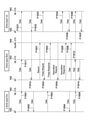
- FIG. 12 shows a sequence chart diagram of the frequency band change processing of the link after disconnection from the NonML-STA in the present embodiment.
- AP102, ML-STA103, and NonML-STA104 transmit and receive data following the data transmission / reception (F904, F905, F913, F914, F934 to F937, F926) shown in FIGS. 9 and 10. It shall be.
- the NonML-STA 104 disconnects from the AP102 due to the end of data to be transmitted / received.
- the wireless LAN control unit 211 of the NonML-STA 104 transmits a De-authentication frame to the AP 102 (F1221).
- AP102 disconnects from NonML-STA104 (S1101).
- data transmission / reception between the AP102 and the ML-STA103 continues (F1201, F1211, F1212, F1231, F1232), while the AP102 is used as necessary (for example, the degree of congestion in the surrounding wireless environment (communication status)).
- the frequency band can be restored and changed to the synchronous mode (by input operation by the user, etc.).
- the communication mode control unit 207 of the AP 102 determines that the condition regarding the change of the communication mode is satisfied according to the communication status when the NonML-STA 104 disconnects from the AP 102.
- the multi-link communication control unit 206 of the AP 102 decides to restore the frequency band changed by F933, and the communication mode control unit 207 decides to change to the synchronous mode. Then, the wireless LAN control unit 201a transmits a channel switch anchorancement to the ML-STA103 (F1202, S1102). As a result, AP102 notifies ML-STA of the change of the frequency band of the link and the changed frequency band. After that, the multi-link communication control unit 206 of AP102 and ML-STA103 changes the link (F1233). In this example, AP102 returns the link of 1ch in the 6GHz band to 100ch in the 5GHz band. After that, AP102 transmits / receives data to / from ML-STA103 by multi-link communication (S1103, F1203, F1204, F1213, F1214, F1234, F1235).
- the multi-link communication control unit 206 changes the frequency band used regardless of the determination of the communication mode control unit 207, and then the communication mode control unit 207 changes the communication mode. May be configured to determine.
- the AP supporting the multi-link communication and the STA are performing the multi-link communication in the synchronous mode
- the STA not supporting the multi-link connects to the AP at the same time. Change the link to a frequency band where transmission and reception can be performed. As a result, it is possible to suppress a decrease in communication throughput in an STA that supports multi-link communication.
- the procedure for the AP to return to the frequency band and communicate in the synchronous mode has also been described.
- This embodiment is an embodiment of a process in which NonML-STA communicates with AP in a state where AP and ML-STA communicate with AP. Since the configuration of the wireless communication system and the configurations of AP102, ML-STA103, and NonML-STA104 are the same as those of the first embodiment, the description thereof will be omitted.
- FIG. 5 is a flowchart of the connection process with the ML-STA 103 executed by the AP 102 in the present embodiment, which is the same as the first embodiment.
- FIG. 13 is a sequence chart diagram of connection processing executed by AP102 and ML-STA103 in the present embodiment.
- the AP102 and the ML-STA103 have wireless LAN control units 201a, 201b, and 201c capable of communicating in any of the 2.4 GHz band, 5 GHz band, and 6 GHz band, respectively.
- the frequency at which the AP102 and the ML-STA103 communicate the management frame for connection processing (Management frame) is 2.4 GHz, and the connection in other frequency bands is also controlled by the communication. It should be noted that the use of 2.4 GHz is an example, and the frequency for transmitting and receiving the management frame is not limited to this.
- the management frame is as described in the first embodiment.
- the multi-link communication control unit 206 of AP102 optionally determines the transmission / reception parameters (S504, F1306).
- the transmission / reception parameter is information (parameter) for determining how to distribute transmission / reception data to each connection when a plurality of connections are established, and is as described in the first embodiment. Is.
- AP102 and ML-STA103 start transmission / reception of data using multi-link communication (S505, F1307 to 1309, F1311 to F1313, F1321 to F1322).
- the wireless LAN control unit 201a of AP102 and ML-STA103 performs multi-link communication on 5ch (2.4GHz band) using an asynchronous mode.
- the wireless LAN control unit 201b of AP102 and ML-STA103 performs multi-link communication on 36ch (5GHz band) using the asynchronous mode.
- the wireless LAN control unit 201c of AP102 and ML-STA103 performs multi-link communication on 1ch (6GHz band) using the asynchronous mode.
- FIG. 14 shows a flowchart of the connection process with the NonML-STA 104 executed by the AP 102 in the present embodiment
- FIG. 15 shows a sequence chart diagram of the connection process executed by the AP 102 and the NonML-STA 104 in the present embodiment. show.
- the NonML-STA 104 has a wireless LAN control unit 211 capable of communicating in any of the 2.4 GHz band, 5 GHz band, and 6 GHz band.
- AP102 and ML-STA103 transmit / receive data following the data transmission / reception (S505, F1307 to 1309, F1311 to F1313, F1321 to F1322) shown in FIGS. 5 and 13. (F1501, F1502, F1511, F1512, F1531, F1532).
- the frequency band determination unit 205 of the AP 102 periodically determines which frequency band is available (S1401).
- AP102 may make the determination depending on the degree of congestion in the surrounding wireless environment, but is not limited thereto.
- the 2.4 GHz band, the 5 GHz band, and the 6 GHz band can be used.
- AP102 periodically transmits Beacon using one of the available frequency bands (F1521).
- the wireless LAN control unit 201b transmits a management frame including a Beacon frame to the NonML-STA 104 using the 5 GHz band.
- the wireless LAN control unit 201b adds frequency band information of AP102 to the Beacon frame.
- the frequency band information is as described above, and the frequency band information may also include information indicating that the AP 102 supports multi-link communication.
- the wireless LAN control unit 211 of the NonML-STA 104 Upon receiving the Beacon frame, the wireless LAN control unit 211 of the NonML-STA 104 transmits a Probe Request frame (F1522) in one available frequency band (here, 5 GHz), and starts a scan operation.
- the wireless LAN control unit 211 of the NonML-STA 104 may add frequency band information of the NonML-STA 104 to the Probe Request frame.
- the frequency band information may include information on the frequency band in which the NonML-STA 104 can be used and information indicating that the NonML-STA 104 does not support multi-link communication. Alternatively, the frequency band information may be configured so as not to include information indicating that the NonML-STA 104 supports multi-link communication.
- the NonML-STA 104 may include its own frequency information in the Authentication Request, Authentication Request, and Authentication Request frames and notify the AP 102.
- the frame analysis unit 203 of the AP 102 analyzes the available frequency band information of the NonML-STA 104 assigned to the Probe Request frame from the NonML-STA 104. Since the frame analysis unit 203 contains information indicating that it does not support multi-link communication (or does not include information indicating that it supports multi-link communication), the NonML-STA 104 Detects that it does not support multi-link communication.
- the communication mode control unit 207 of AP102 determines that the condition for changing the communication mode is not satisfied. Therefore, the multi-link communication control unit 206 does not change the frequency band of the link as in the first embodiment.
- the wireless LAN control unit 201b of the AP102 transmits a Probe Response frame containing information on available frequency bands in response to the Probe Request frame (F1522) from the NonML-STA 104 (F1523).
- the frame analysis unit 213 of the NonML-STA 104 detects the frequency corresponding to the AP 102 and the channel operating at that frequency from the information of the available frequency band included in the Probe Response frame from the AP 102.
- AP102 and NonML-STA104 establish a connection by communication via the wireless LAN control unit 201b and the wireless LAN control unit 211 (S1403, F1524, F1525).
- communication processing such as WPA, WPA2, and WPA3 may be performed after that.
- a connection without encryption is described, but the present invention is not limited to this.
- AP102 and ML-STA103 continue to perform multi-link communication (in asynchronous mode) capable of simultaneously transmitting and receiving (F1503 to F1505, F1513 to F1514, F1533 to F1537). Further, AP102 and NonML-STA104 perform data transmission / reception using single link communication in one frequency band (F1526).
- the process of restoring the frequency band used by AP102 for multi-link communication with ML-STA103 after the NonML-STA 104 disconnects from AP102 is the same as that of the first embodiment (described in FIGS. 11 and 12). See). That is, when the nonML-STA 104 disconnects from the AP 102, the communication mode control unit 207 of the AP 102 determines that the condition regarding the change of the communication mode is satisfied according to the communication status. The AP 102 then transmits a channel switch explanation to the ML-STA 103, as described with reference to FIG. 12 (F1202). As a result, AP102 notifies ML-STA of the change of the frequency band of the link and the changed frequency band. After that, the multi-link communication control unit 206 of AP102 and ML-STA103 changes the link (F1233).
- the STA that does not support the multilink becomes the AP. Even when connecting, it can be connected appropriately. As a result, the STA corresponding to the AP and the multi-link can continue the communication without lowering the communication throughput.
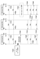
- FIG. 16 is a sequence chart diagram of the re-change processing of the used frequency band based on the type of transmission data in the present embodiment.
- the types of transmitted data are distinguished by the access category defined in IEEE802.11e. It is assumed that AC_VO (access category for voice data) is set in advance in the multi-link communication control unit 206 of the AP 102 as an access category that is a condition for changing to the asynchronous mode. AC_VO is an access category with the highest transmission priority.
- AP102 and ML-STA103 are in a state of communicating in a synchronous mode with 2.4 GHz 5 ch, 5 GHz 36 ch, and 5 GHz 100 ch as links, for example, by the procedure shown in the first embodiment. , F1602, F1611, F1622, F1621, F1622).
- F1602, F1611, F1622, F1621, F1622 it is assumed that an application that transmits / receives data in both directions in real time is executed in AP102 and ML-STA103.
- the data addressed to ML-STA103 generated by the application that transmits / receives data in both directions in real time enters the transmission queue in the communication unit 307 of AP102 as a frame of the AC_VO category.
- the multi-link communication control unit 206 of the AP 102 detects that the transmission data is a specific type of data that satisfies the conditions for changing the communication mode according to the access category of the data (transmission data) addressed to the ML-STA 103. ..
- the communication mode control unit 207 determines that the condition for changing the communication mode is satisfied.
- the frequency interval becomes 605 MHz, which is larger than FAP and FML -STA. Therefore, AP102 and ML- STA103 transmit and receive between 36ch in the 5GHz band and 1ch in the 6GHz band without interference in the device. Will be able to be executed at the same time.
- the wireless LAN control unit 201a of the AP102 transmits a channel switch anchorance to the ML-STA103, and notifies the change of the frequency band of the link and the changed frequency band (F1604).
- the multi-link communication control unit 206 of AP102 and ML-STA103 performs control for changing the link (F1623).
- the multi-link communication control unit 206 of the AP 102 determines that transmission and reception may be executed simultaneously on any link in the multi-link communication with the ML-STA 103. That is, the multi-link communication control unit 206 of the AP 102 determines whether communication may be performed in the synchronous mode or the asynchronous mode.
- the decision is notified to the ML-STA 103 by the wireless LAN control unit 201a of the AP102. After that, AP102 transmits / receives data to / from ML-STA103 by multi-link communication (F1605 to F1607, F1613 to F1615, F1624 to F1627).
- the mode is changed from the synchronous mode to the asynchronous mode on condition that the frame of the AC_VO category is in the transmission queue, but other access categories may be used. Further, instead of the access category, a parameter indicating the transmission priority of other data may be a condition.
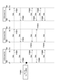
- FIG. 17 is a sequence chart diagram of the re-change processing of the frequency band used based on the type (access category) of the transmission data in the present embodiment.
- the multi-link communication control unit 206 of the AP 102 determines that the frame of the AC_VO category is not in the transmission queue (F1701).
- the multi-link communication control unit 106 determines, for example, on the condition that the frame of the AC_VO category does not enter the transmission queue for a predetermined fixed time (for example, 300 seconds).
- the communication mode control unit 207 of the AP 102 determines that the condition regarding the change of the communication mode is satisfied according to the communication status.
- the subsequent processing (F1702 to F1725) is the same as the description of FIG. 12 described in the first embodiment, and thus the description thereof will be omitted.
- the asynchronous mode is used. Change to the frequency band that allows multi-link communication with, and enable transmission and reception at the same time. As a result, it is possible to prevent the use of the application that transmits / receives data in both directions in real time from being affected even in the state of multi-link communication in the synchronous mode.
- This embodiment is used in an application in which data is transmitted and received in real time in both directions in a state where AP and ML-STA are performing multi-link communication using a frequency band capable of simultaneously transmitting and receiving. It is an embodiment regarding processing. Since the configuration of the wireless communication system and the configurations of AP102, ML-STA103, and NonML-STA104 are the same as those of the first embodiment, the description thereof will be omitted. Similar to the third embodiment, in the present embodiment, an example in which the access category defined by IEEE802.11e is used as the type of transmission data will be described.
- FIG. 18 is a sequence chart diagram of processing based on the type of transmission data in the present embodiment.
- the AP102 and the ML-STA103 are in a state of communicating in a synchronous mode using 2.4 GHz 5 ch, 5 GHz 36 ch, and 6 GHz 1 ch as links (F1801, F1802, F1811, F1812, F1821, F1822).
- F1801, F1802, F1811, F1812, F1821, F1822 links
- AC_VO voice data access category
- AC_VO is set in advance in the multi-link communication control unit 206 of the AP 102 as an access category that is a condition for changing to the asynchronous mode.
- AC_VO is an access category with the highest transmission priority.
- the data addressed to ML-STA103 generated by the application that transmits / receives data in both directions in real time enters the transmission queue in the communication unit 307 of AP102 as a frame of the AC_VO category.
- the multi-link communication control unit 206 of the AP 102 detects that the transmission data is a specific type of data that satisfies the conditions for changing the communication mode according to the access category of the data (transmission data) addressed to the ML-STA 103. ..
- the communication mode control unit 207 determines that the condition for changing the communication mode is satisfied.
- the multi-link communication control unit 206 of the AP 102 determines the frequency band used in the link so that the frequency interval between the links is larger than that of either F AP or F ML-STA . In this example, since the multi-link communication is already performed using the frequency band capable of simultaneously transmitting and receiving, the multi-link communication control unit 206 does not change the frequency band of the link. Subsequently, the AP102 transmits / receives data by multi-link communication (F1804 to F1806, F1813 to F1815, F1823 to F1826) using a mode capable of simultaneous transmission / reception with the ML-STA103.
- the AP102 can continue to communicate with the ML-STA 103 without changing the frequency band of the link even after the AC_VO category frame is not put in the transmission queue. On the other hand, the AP102 can also change the frequency band to the synchronous mode due to reasons such as the communication status of the used frequency band becoming congested. Since the process of returning to the synchronous mode is the same as the description of FIG. 17 described in the third embodiment, the description thereof will be omitted.
- data is transmitted and received in real time in both directions in a state where the AP and the STA corresponding to the multi-link are performing multi-link communication using a frequency band capable of simultaneously transmitting and receiving.
- you start using such an application you can take appropriate action.
- the present invention supplies a program that realizes one or more functions of the above-described embodiment to a system or device via a network or storage medium, and one or more processors in the computer of the system or device reads and executes the program. It can also be realized by the processing to be performed. It can also be realized by a circuit (for example, ASIC) that realizes one or more functions.
- a circuit for example, ASIC
Landscapes
- Engineering & Computer Science (AREA)
- Signal Processing (AREA)
- Computer Networks & Wireless Communication (AREA)
- Computer Security & Cryptography (AREA)
- Mobile Radio Communication Systems (AREA)
- Communication Control (AREA)
Abstract
Description
IEEE802.11シリーズの規格に準拠する通信装置であって、
各周波数帯において送信と受信を独立に行う第1のモード、又は、各周波数帯において同時に送信又は受信を行う第2のモードのいずれかの通信モードで通信を行う通信手段と、
前記通信モードの変更に関する所定の条件を満たすかを判定する判定手段と、
前記判定手段により前記所定の条件を満たすと判定された場合に、変更後の前記通信モードで通信を行うために使用する1つ以上の周波数帯を決定する決定手段と、を有し、
前記通信手段が前記第1のモード又は前記第2のモードで複数の周波数帯の各周波数帯を使用して第1の他の通信装置と通信している間に、前記判定手段により前記所定の条件を満たすと判定された場合に、前記決定手段は、前記複数の周波数帯に基づいて、変更後の前記通信モードで通信を行うための複数の周波数帯を決定し、前記通信手段は、前記決定された複数の周波数帯を使用して、変更後の前記通信モードで前記第1の他の通信装置と通信する。
本実施形態は、APとML-STAが、同期モードを含む通信モードでマルチリンク通信をしている状態において、NonML-STAがAPに接続する場合に、使用するリンクを、同時に送信と受信を実行できる周波数帯に変更する処理についての実施形態である。上記のように、ML-STAはマルチリンク技術に対応したSTA(ステーション/端末装置)であり、NonML-STAはマルチリンク技術に対応していないSTAを示す。なお、リンクとは、データ送受信ができるようになった周波数チャネル(周波数帯)を指す。
図1に、本実施形態におけるネットワークの構成例を示す。図1は、IEEE802.11beに対応する通信装置として、AP(アクセスポイント)102と、ML-STA103、NonML-STA104を含んだ構成を示している。AP102は、マルチリンク技術に対応する通信装置である。AP102が形成するネットワークは円101で示される。AP102が送受信する信号を、ML-STA103およびNonML-STA104は送受信することができる。
続いて、本実施形態における通信装置(AP102、ML-STA103、NonML-STA104)の構成について説明する。まず、図2Aと図2Bを参照して、通信装置の機能構成について説明する。図2Aに、AP102とML-STA103の機能構成例のブロック図を示す。AP102とML-STA103はそれぞれ、機能構成の一例として無線LAN制御部201a、201b、201c、フレーム生成部202、フレーム解析部203、UI(ユーザインタフェース)制御部204、周波数帯決定部205、マルチリンク通信制御部206、及び通信モード制御部207を備える。
続いて、本実施形態における各通信装置の処理の流れについて説明する。まず、マルチリンク技術に対応したAP102とML-STA103において予め設定される、機器内妨害が発生しないために必要な周波数間隔値について説明する。非同期モードでのマルチリンク通信の場合(同一機器で送信と受信を同時に行い得る場合)、送信と受信に使用するそれぞれのリンクの周波数間隔が小さい場合、送信信号が受信回路に妨害波として混入し、受信特性に悪影響を与える機器内妨害が生じることがある。機器内妨害の発生を防ぐために、AP102とML-STA103において、機器内妨害が発生しないために必要な周波数間隔値が設定される。
図5と図6を用いて、AP102とML-STA103との接続処理(データ送受信を行うまでの処理)を説明する。図5に、本実施形態におけるAP102により実行されるML-STA103との接続処理のフローチャートを示し、図6に、本実施形態における、AP102とML-STA103により実行される接続処理のシーケンスチャート図を示す。上述したように、AP102とML-STA103はそれぞれ2.4GHz帯、5GHz帯、6GHz帯のいずれかで通信可能な無線LAN制御部201a、201b、201cを有する。
・5chと36ch間の周波数間隔: 2708MHz
・36chと100ch間の周波数間隔: 160MHz
・5chと100ch間の周波数間隔: 3028MHz
これらの間隔値と、FAP(=200MHz)とFML-STA(=300MHz)とを比較すると、36chと100chの周波数間隔がFAPとFML-STAのいずれよりも小さい。よって、AP102の通信モード制御部207は、36chと100chのリンク間では、同時に送信と受信を行わずに(非同期モードを用いずに)、同期モードで通信すること決定する。一方、5chと36ch、5chと100chのリンク間では、周波数間隔がFAP、FML-STAのいずれよりも大きい。よって、AP102の通信モード制御部207は、これらのリンク間では、同時に送信と受信を行ってもよい(つまり、同期モードと非同期モードのどちらでもよい)ことを決定する。AP102の無線LAN制御部201aは当該決定を送受信パラメータとして(送受信パラメータに含めて)ML-STA103に通知する。
次に、図8および図9を用いて、AP102がML-STA103とマルチリンク通信を確立した後の、AP102とNonML-STA104との接続処理、及び、AP102による機器内妨害を考慮した使用周波数帯の変更処理について説明する。図8に、本実施形態におけるAP102により実行されるNonML-STA104との接続処理のフローチャートを示し、図9に、本実施形態における、AP102とNonML-STA104により実行される接続処理のシーケンスチャート図を示す。上述したように、NonML-STA104は2.4GHz帯、5GHz帯、6GHz帯のいずれかで通信可能な無線LAN制御部211を有する。
次に、図11および図12を用いて、NonML-STA104がAP102との接続を切断した後、AP102がML-STA103とのマルチリンク通信に使用する周波数帯を元に(変更前に)戻す処理について説明する。NonML-STA104がAP102との接続を切断した後も、AP102は引き続きリンクの周波数帯を変えずにML-STA103と通信することができる。一方で、AP102は、使用周波数帯の通信状況が混雑してきた等の理由により、周波数帯を元に戻して同期モードに変更することもできる。
本実施形態は、APとML-STAが、マルチリンク通信をしている状態において、NonML-STAがAPと通信を行う場合の処理についての実施形態である。無線通信システムの構成、AP102、ML-STA103、NonML-STA104の構成は第1実施形態と同様であるため、これらについての記載は省略する。なお、機器内妨害が発生しないために必要な周波数間隔値Fについても第1実施形態と同様である。すなわち、AP102とML-STA103の機器内妨害が発生しないために必要な周波数間隔値Fを、それぞれFAP=200MHzとFML-STA=300MHzとする。
図5と図13を用いて、AP102とML-STA103との接続処理(データ送受信を行うまでの処理)を説明する。図5は、本実施形態におけるAP102により実行されるML-STA103との接続処理のフローチャートであり、第1実施形態と同様である。図13は、本実施形態における、AP102とML-STA103により実行される接続処理のシーケンスチャート図である。上述したように、AP102とML-STA103はそれぞれ2.4GHz帯、5GHz帯、6GHz帯のいずれかで通信可能な無線LAN制御部201a、201b、201cを有する。
・5chと36ch間の周波数間隔: 2708MHz
・36chと6GHz帯1ch間の周波数間隔: 605MHz
・5chと6GHz帯1ch間の周波数間隔: 3473MHz
これらの間隔値と、FAP(=200MHz)とFML-STA(=300MHz)とを比較すると、いずれの周波数間隔もFAPとFML-STAより大きい。よって、AP102の通信モード制御部207は、各リンク間では同時に送信と受信を行ってもよい(つまり、同期モードと非同期モードのどちらでもよい)ことを決定する。AP102の無線LAN制御部201aは当該決定を送受信パラメータとして(送受信パラメータに含めて)ML-STA103に通知する。
次に、図14および図15を用いて、AP102がML-STA103とマルチリンク通信を確立した後の、AP102とNonML-STA104との接続処理について説明する。図14に、本実施形態におけるAP102により実行されるNonML-STA104との接続処理のフローチャートを示し、図15に、本実施形態における、AP102とNonML-STA104により実行される接続処理のシーケンスチャート図を示す。上述したように、NonML-STA104は2.4GHz帯、5GHz帯、6GHz帯のいずれかで通信可能な無線LAN制御部211を有する。
NonML-STA104がAP102との接続を切断した後、AP102がML-STA103とのマルチリンク通信に使用する周波数帯を元に戻す処理については、第1実施形態と同様(図11と図12の説明を参照)である。すなわち、AP102の通信モード制御部207が、NonML-STA104がAP102との接続を切断した場合に、通信状況に応じて、通信モードの変更に関する条件を満たすと判定する。その後、AP102は、図12を参照して説明したように、ML-STA103に対し、channel switch announcementを送信する(F1202)。これにより、AP102は、リンクの周波数帯の変更と、変更後の周波数帯をML-STAに通知する。その後、AP102とML-STA103のマルチリンク通信制御部206は、リンクを変更する(F1233)。
本実施形態は、APとML-STAが、同期モードでマルチリンク通信をしている状態において、データを双方向でリアルタイムに送受信するようなアプリケーションにおいて使用する場合に、同時に送信と受信を実行可能なモード(非同期モード)に変更する処理についての実施形態である。無線通信システムの構成、AP102、ML-STA103、NonML-STA104の構成は第1実施形態と同様であるため、これらについての記載は省略する。本実施形態ではIEEE802.11eで規定されているアクセスカテゴリに基づいて、マルチリンク通信の通信モードを非同期モードに変更する。アクセスカテゴリ(AC)は、フレーム(パケット)送信優先度を示すものである。
図16を用いて、AP102とML-STA103がマルチリンク通信を確立した後に、送信データの種類に応じて非同期モードに変更する処理について説明する。図16は、本実施形態における、送信データの種類に基づく使用周波数帯の再変更処理のシーケンスチャート図である。本実施形態において、送信データの種類は、IEEE802.11eに規定されるアクセスカテゴリにより区別されるものとする。AP102のマルチリンク通信制御部206には、予め、非同期モードに変更する条件となるアクセスカテゴリとして、AC_VO(音声データ用アクセスカテゴリ)が設定されものとする。AC_VOは、最も高い送信優先度を有するアクセスカテゴリである。
次に図17を用いて、AC_VOカテゴリのフレームがAP102の送信キューに入らない状態になった後、AP102がML-STA103とのマルチリンク通信に使用する周波数帯を元に戻す処理について説明する。データを双方向でリアルタイムに送受信するアプリケーションの使用が終了した等の理由で、AC_VOカテゴリのフレームが送信キューに入らない状態になった後も、引き続きリンクの周波数帯を変えずにML-STA103と通信することができる。一方で、使用周波数帯の通信状況が混雑してきた等の理由により、周波数帯を元に戻して同期モードに変更することもできる。
本実施形態は、APとML-STAが同時に送信と受信を実行できる周波数帯を用いてマルチリンク通信をしている状態において、データを双方向でリアルタイムに送受信するようなアプリケーションにおいて使用する場合の処理に関する実施形態である。無線通信システムの構成、AP102、ML-STA103、NonML-STA104の構成は第1実施形態と同様であるため、これらについての記載は省略する。第3実施形態と同様に、本実施形態では、送信データの種類として、IEEE802.11eで規定されているアクセスカテゴリを用いる例について説明する。
図18を用いて、AP102とML-STA103がマルチリンク通信を確立した後に、送信データの種類に応じて行う処理について説明する。図18は、本実施形態における、送信データの種類に基づく処理のシーケンスチャート図である。AP102とML-STA103は、2.4GHzの5ch、5GHzの36ch、6GHzの1chをリンクとして同期モードで通信している状態とする(F1801、F1802、F1811、F1812、F1821、F1822)。ここで、AP102とML-STA103において、データを双方向でリアルタイムに送受信するようなアプリケーションが実行されているものとする。また、AP102のマルチリンク通信制御部206には、予め、非同期モードに変更する条件となるアクセスカテゴリとして、AC_VO(音声データ用アクセスカテゴリ)が設定されものとする。AC_VOは、最も高い送信優先度を有するアクセスカテゴリである。
AP102は、AC_VOカテゴリのフレームが送信キューに入らない状態になった後も、引き続きリンクの周波数帯を変えずにML-STA103と通信することができる。一方で、AP102は、使用周波数帯の通信状況が混雑してきた等の理由により、周波数帯を変更して同期モードに変更することもできる。同期モードに戻す処理については、第3実施形態において説明した図17の説明と同様のため、説明を省略する。
本発明は、上述の実施形態の1以上の機能を実現するプログラムを、ネットワーク又は記憶媒体を介してシステム又は装置に供給し、そのシステム又は装置のコンピュータにおける1つ以上のプロセッサーがプログラムを読出し実行する処理でも実現可能である。また、1以上の機能を実現する回路(例えば、ASIC)によっても実現可能である。
Claims (12)
- IEEE802.11シリーズの規格に準拠する通信装置であって、
各周波数帯において送信と受信を独立に行う第1のモード、又は、各周波数帯において同時に送信又は受信を行う第2のモードのいずれかの通信モードで通信を行う通信手段と、
前記通信モードの変更に関する所定の条件を満たすかを判定する判定手段と、
前記判定手段により前記所定の条件を満たすと判定された場合に、変更後の前記通信モードで通信を行うために使用する1つ以上の周波数帯を決定する決定手段と、を有し、
前記通信手段が前記第1のモード又は前記第2のモードで複数の周波数帯の各周波数帯を使用して第1の他の通信装置と通信している間に、前記判定手段により前記所定の条件を満たすと判定された場合に、前記決定手段は、前記複数の周波数帯に基づいて、変更後の前記通信モードで通信を行うための複数の周波数帯を決定し、前記通信手段は、前記決定された複数の周波数帯を使用して、変更後の前記通信モードで前記第1の他の通信装置と通信することを特徴とする通信装置。 - 前記通信手段は、前記複数の周波数帯のうち、2つの周波数帯の間の周波数間隔が、所定の間隔より小さい場合に、当該2つの周波数帯において前記第2のモードで前記第1の他の通信装置と通信し、前記2つの周波数帯の間の周波数間隔が、前記所定の間隔以上の場合に、当該2つの周波数帯において前記第1のモード又は前記第2のモードで前記第1の他の通信装置と通信することを特徴とする請求項1に記載の通信装置。
- 前記所定の間隔は、前記通信装置と前記第1の他の通信装置の両方が前記2つの周波数帯で送信と受信とを同時に行うために必要な周波数間隔値であることを特徴とする請求項2に記載の通信装置。
- 前記複数の周波数帯のうち、前記通信手段が前記第2のモードで前記第1の他の通信装置と通信を行っている第1の周波数帯において、複数の周波数帯を使用した通信に対応しない第2の他の通信装置により接続が行われた場合に、前記判定手段は、前記所定の条件を満たすと判定し、
、前記第1の周波数帯と、前記複数の周波数帯のうち前記第1の周波数帯に隣接する1つ以上の周波数帯との間の周波数間隔が前記所定の間隔より小さい場合に、前記決定手段は、前記第1の周波数帯と前記隣接する1つ以上の周波数帯との間の周波数間隔が前記所定の間隔以上となるように、前記隣接する1つ以上の周波数帯を変更し、変更された複数の周波数帯を使用することを決定することを特徴とする請求項2または3に記載の通信装置。 - 前記通信手段が前記変更された複数の周波数帯を使用して変更後の前記通信モードで前記第1の他の通信装置と通信している間に、前記第2の他の通信装置が前記第1の周波数帯において前記通信装置との接続を切断した場合、前記判定手段は、通信状況に応じて前記所定の条件を満たすと判定し、
前記決定手段は、前記隣接する1つ以上の周波数帯を変更前の周波数帯に戻した複数の周波数帯を使用することを決定することを特徴とする請求項4に記載の通信装置。 - 前記複数の周波数帯のうち、前記通信手段が前記第1のモードで前記第1の他の通信装置と通信を行っている第2の周波数帯において、複数の周波数帯を使用した通信に対応しない第2の他の通信装置により接続が行われた場合に、前記判定手段は、前記所定の条件を満たさないと判定することを特徴とする請求項2または3に記載の通信装置。
- 前記第2の周波数帯において前記第2の他の通信装置により接続が行われた後に、前記第2の他の通信装置が前記第2の周波数帯において前記通信装置との接続を切断した場合、前記判定手段は、通信状況に応じて前記所定の条件を満たすと判定し、
前記決定手段は、前記第2の周波数帯と、前記複数の周波数帯において前記第2の周波数帯と隣接する1つ以上の周波数帯との間の周波数間隔が前記所定の間隔より小さくなるように、前記隣接する1つ以上の周波数帯を変更し、変更された複数の周波数帯を使用することを決定することを特徴とする請求項6に記載の通信装置。 - 前記第1の他の通信装置へ送信するために生成されたデータが特定の種類のデータであるかを検出する検出手段を更に有し、
前記通信手段が前記複数の周波数帯のうち1つ以上の周波数帯において前記第2のモードで前記第1の他の通信装置と通信を行っている間に、前記検出手段により前記データが前記特定の種類のデータであることが検出された場合、前記判定手段は、前記所定の条件を満たすと判定し、
前記決定手段は、前記複数の周波数帯における各周波数帯の周波数間隔が前記所定の間隔より小さい場合に、当該各周波数帯の周波数間隔が前記所定の間隔以上となるように、前記複数の周波数帯における少なくとも1つの周波数帯を変更し、変更された複数の周波数帯を使用することを決定することを特徴とする請求項2または3に記載の通信装置。 - 前記通信手段が前記変更された複数の周波数帯を使用して変更後の前記通信モードで前記第1の他の通信装置と通信している間に、前記検出手段により前記データが前記特定の種類のデータでないことが検出された場合、前記判定手段は、通信状況に応じて前記所定の条件を満たすと判定し、
前記決定手段は、前記少なくとも1つの周波数帯を変更前の周波数帯に戻した複数の周波数帯を使用することを決定することを特徴とする請求項8に記載の通信装置。 - 前記検出手段は、IEEE802.11eに規定されるアクセスカテゴリに基づいて、前記データが前記特定の種類のデータであるかを検出することを特徴とする請求項8または9に記載の通信装置。
- IEEE802.11シリーズの規格に準拠する通信装置の制御方法であって、
各周波数帯において送信と受信を独立に行う第1のモード、又は、各周波数帯において同時に送信又は受信を行う第2のモードのいずれかの通信モードで通信を行う通信工程と、
前記通信モードの変更に関する所定の条件を満たすかを判定する判定工程と、
前記判定工程において前記所定の条件を満たすと判定された場合に、変更後の前記通信モードで通信を行うために使用する1つ以上の周波数帯を決定する決定工程と、を有し、
前記通信工程において前記第1のモード又は前記第2のモードで複数の周波数帯の各周波数帯を使用して第1の他の通信装置と通信している間に、前記判定工程において前記所定の条件を満たすと判定された場合に、前記決定工程では、前記複数の周波数帯に基づいて、変更後の前記通信モードで通信を行うための複数の周波数帯を決定し、
当該決定の後に、前記通信工程において前記決定された複数の周波数帯を使用して、変更後の前記通信モードで前記第1の他の通信装置と通信することを特徴とする制御方法。 - コンピュータを、請求項1から10のいずれか1項に記載の通信装置として機能させるためのプログラム。
Priority Applications (5)
| Application Number | Priority Date | Filing Date | Title |
|---|---|---|---|
| KR1020237006495A KR20230044469A (ko) | 2020-08-04 | 2021-05-10 | 통신 장치, 통신 장치의 제어 방법 및 컴퓨터 프로그램 |
| EP21852837.0A EP4195842A4 (en) | 2020-08-04 | 2021-05-10 | COMMUNICATION DEVICE, METHOD FOR CONTROLLING THE COMMUNICATION DEVICE AND PROGRAM |
| CN202180057888.0A CN116210318A (zh) | 2020-08-04 | 2021-05-10 | 通信装置、通信装置的控制方法和程序 |
| BR112023000606A BR112023000606A2 (pt) | 2020-08-04 | 2021-05-10 | Dispositivo de comunicação, método para controlar dispositivo de comunicação, e suporte legível por computador |
| US18/150,901 US20230155754A1 (en) | 2020-08-04 | 2023-01-06 | Communication device, method for controlling communication device, and medium |
Applications Claiming Priority (2)
| Application Number | Priority Date | Filing Date | Title |
|---|---|---|---|
| JP2020132538A JP7633776B2 (ja) | 2020-08-04 | 2020-08-04 | 通信装置、通信装置の制御方法、及び、プログラム |
| JP2020-132538 | 2020-08-04 |
Related Child Applications (1)
| Application Number | Title | Priority Date | Filing Date |
|---|---|---|---|
| US18/150,901 Continuation US20230155754A1 (en) | 2020-08-04 | 2023-01-06 | Communication device, method for controlling communication device, and medium |
Publications (1)
| Publication Number | Publication Date |
|---|---|
| WO2022030058A1 true WO2022030058A1 (ja) | 2022-02-10 |
Family
ID=80117268
Family Applications (1)
| Application Number | Title | Priority Date | Filing Date |
|---|---|---|---|
| PCT/JP2021/017612 Ceased WO2022030058A1 (ja) | 2020-08-04 | 2021-05-10 | 通信装置、通信装置の制御方法、及び、プログラム |
Country Status (7)
| Country | Link |
|---|---|
| US (1) | US20230155754A1 (ja) |
| EP (1) | EP4195842A4 (ja) |
| JP (1) | JP7633776B2 (ja) |
| KR (1) | KR20230044469A (ja) |
| CN (1) | CN116210318A (ja) |
| BR (1) | BR112023000606A2 (ja) |
| WO (1) | WO2022030058A1 (ja) |
Families Citing this family (3)
| Publication number | Priority date | Publication date | Assignee | Title |
|---|---|---|---|---|
| US20230052555A1 (en) * | 2021-08-10 | 2023-02-16 | Texas Instruments Incorporated | Devices and methods for asynchronous and syncrhonous wireless communications utilizing a single radio |
| US20250103090A1 (en) * | 2023-09-27 | 2025-03-27 | Ati Technologies Ulc | Devices, systems, and methods for dynamically changing frequencies of clocks for the data link layer without downtime |
| WO2025163806A1 (ja) * | 2024-01-31 | 2025-08-07 | Ntt株式会社 | アクセスポイント及び集中制御装置 |
Citations (2)
| Publication number | Priority date | Publication date | Assignee | Title |
|---|---|---|---|---|
| JP2018050133A (ja) | 2016-09-20 | 2018-03-29 | キヤノン株式会社 | 通信装置、制御方法、及びプログラム |
| JP2020132538A (ja) | 2019-02-14 | 2020-08-31 | 株式会社ファーマフーズ | サーチュイン遺伝子発現増加剤及び細胞周期正常化剤 |
Family Cites Families (5)
| Publication number | Priority date | Publication date | Assignee | Title |
|---|---|---|---|---|
| WO2014065611A1 (ko) * | 2012-10-24 | 2014-05-01 | 한국전자통신연구원 | 무선랜 시스템에서의 자원 할당 방법 및 장치, 통신 방법 및 통신 단말 |
| WO2014136398A1 (ja) * | 2013-03-07 | 2014-09-12 | パナソニック株式会社 | 通信装置および通信方式の判定方法 |
| WO2017111567A2 (ko) * | 2015-12-24 | 2017-06-29 | 주식회사 윌러스표준기술연구소 | 불연속 채널을 이용한 무선 통신 방법 및 무선 통신 단말 |
| US11337263B2 (en) * | 2017-01-19 | 2022-05-17 | Qualcomm Incorporated | Packet based link aggregation architectures |
| US10959153B2 (en) * | 2017-09-11 | 2021-03-23 | Qualcomm Incorporated | Techniques for multi-link aggregation signaling |
-
2020
- 2020-08-04 JP JP2020132538A patent/JP7633776B2/ja active Active
-
2021
- 2021-05-10 KR KR1020237006495A patent/KR20230044469A/ko active Pending
- 2021-05-10 WO PCT/JP2021/017612 patent/WO2022030058A1/ja not_active Ceased
- 2021-05-10 CN CN202180057888.0A patent/CN116210318A/zh active Pending
- 2021-05-10 BR BR112023000606A patent/BR112023000606A2/pt unknown
- 2021-05-10 EP EP21852837.0A patent/EP4195842A4/en active Pending
-
2023
- 2023-01-06 US US18/150,901 patent/US20230155754A1/en active Pending
Patent Citations (2)
| Publication number | Priority date | Publication date | Assignee | Title |
|---|---|---|---|---|
| JP2018050133A (ja) | 2016-09-20 | 2018-03-29 | キヤノン株式会社 | 通信装置、制御方法、及びプログラム |
| JP2020132538A (ja) | 2019-02-14 | 2020-08-31 | 株式会社ファーマフーズ | サーチュイン遺伝子発現増加剤及び細胞周期正常化剤 |
Non-Patent Citations (2)
| Title |
|---|
| INSUN JANG (LG ELECTRONICS): "Channel Access for Multi-link Operation", IEEE DRAFT; 11-19-1144-06-00BE-CHANNEL-ACCESS-FOR-MULTI-LINK-OPERATION, IEEE-SA MENTOR, PISCATAWAY, NJ USA, vol. 802.11 EHT; 802.11be, no. 6, 14 November 2019 (2019-11-14), Piscataway, NJ USA , pages 1 - 14, XP068164747 * |
| See also references of EP4195842A4 |
Also Published As
| Publication number | Publication date |
|---|---|
| US20230155754A1 (en) | 2023-05-18 |
| CN116210318A (zh) | 2023-06-02 |
| JP2022029278A (ja) | 2022-02-17 |
| EP4195842A4 (en) | 2024-08-28 |
| JP7633776B2 (ja) | 2025-02-20 |
| KR20230044469A (ko) | 2023-04-04 |
| EP4195842A1 (en) | 2023-06-14 |
| BR112023000606A2 (pt) | 2023-02-14 |
Similar Documents
| Publication | Publication Date | Title |
|---|---|---|
| KR102724229B1 (ko) | 통신장치, 통신방법, 및, 프로그램 | |
| US20230155754A1 (en) | Communication device, method for controlling communication device, and medium | |
| JP7520515B2 (ja) | 通信装置、制御方法、及びプログラム | |
| US20250024541A1 (en) | Communication devices and control method for the same | |
| JP7453774B2 (ja) | 通信装置、情報処理装置、制御方法、及び、プログラム | |
| JP2026021495A (ja) | 通信装置、通信装置の制御方法、およびそのプログラム | |
| WO2022050218A1 (ja) | 通信装置、制御方法、およびプログラム | |
| US20240244692A1 (en) | Communication apparatus, method for controlling communication apparatus, and storage medium for the same | |
| EP4568416A1 (en) | Communication device, communication method, and program | |
| US12587346B2 (en) | Communication apparatus, control method, and computer-readable storage medium | |
| JP7625398B2 (ja) | 通信装置、制御方法、およびプログラム | |
| JP7682663B2 (ja) | 通信装置、通信方法、およびプログラム | |
| JP7500180B2 (ja) | 通信装置、通信方法及びプログラム | |
| JP7755479B2 (ja) | 通信装置、制御方法、およびそのプログラム | |
| US20260046965A1 (en) | Communication device, method for controlling the same, and storage medium | |
| US20220312314A1 (en) | Communication apparatus, communication method, and storage medium | |
| US20250227790A1 (en) | Communication device and non-transitory computer readable storage medium | |
| JP7183622B2 (ja) | 通信装置及び通信装置のためのコンピュータプログラム | |
| WO2025249364A1 (ja) | 通信装置、制御方法、及びプログラム | |
| JP2025138807A (ja) | 通信装置、通信装置の制御方法、およびそのプログラム | |
| JP2025181627A (ja) | 通信装置、制御方法、及びプログラム | |
| WO2025253829A1 (ja) | 通信装置、制御方法、プログラム | |
| WO2022168393A1 (ja) | 通信装置、通信装置の制御方法、およびプログラム |
Legal Events
| Date | Code | Title | Description |
|---|---|---|---|
| 121 | Ep: the epo has been informed by wipo that ep was designated in this application |
Ref document number: 21852837 Country of ref document: EP Kind code of ref document: A1 |
|
| REG | Reference to national code |
Ref country code: BR Ref legal event code: B01A Ref document number: 112023000606 Country of ref document: BR |
|
| ENP | Entry into the national phase |
Ref document number: 112023000606 Country of ref document: BR Kind code of ref document: A2 Effective date: 20230112 |
|
| ENP | Entry into the national phase |
Ref document number: 20237006495 Country of ref document: KR Kind code of ref document: A |
|
| WWE | Wipo information: entry into national phase |
Ref document number: 2021852837 Country of ref document: EP |
|
| NENP | Non-entry into the national phase |
Ref country code: DE |