WO2022030251A1 - 伝搬時間測定装置 - Google Patents
伝搬時間測定装置 Download PDFInfo
- Publication number
- WO2022030251A1 WO2022030251A1 PCT/JP2021/027198 JP2021027198W WO2022030251A1 WO 2022030251 A1 WO2022030251 A1 WO 2022030251A1 JP 2021027198 W JP2021027198 W JP 2021027198W WO 2022030251 A1 WO2022030251 A1 WO 2022030251A1
- Authority
- WO
- WIPO (PCT)
- Prior art keywords
- signal
- oscillator
- propagation time
- reverberation
- received signal
- Prior art date
- Legal status (The legal status is an assumption and is not a legal conclusion. Google has not performed a legal analysis and makes no representation as to the accuracy of the status listed.)
- Ceased
Links
Images







Classifications
-
- G—PHYSICS
- G01—MEASURING; TESTING
- G01F—MEASURING VOLUME, VOLUME FLOW, MASS FLOW OR LIQUID LEVEL; METERING BY VOLUME
- G01F1/00—Measuring the volume flow or mass flow of fluid or fluent solid material wherein the fluid passes through a meter in a continuous flow
- G01F1/66—Measuring the volume flow or mass flow of fluid or fluent solid material wherein the fluid passes through a meter in a continuous flow by measuring frequency, phase shift or propagation time of electromagnetic or other waves, e.g. using ultrasonic flowmeters
- G01F1/667—Arrangements of transducers for ultrasonic flowmeters; Circuits for operating ultrasonic flowmeters
-
- G—PHYSICS
- G01—MEASURING; TESTING
- G01F—MEASURING VOLUME, VOLUME FLOW, MASS FLOW OR LIQUID LEVEL; METERING BY VOLUME
- G01F1/00—Measuring the volume flow or mass flow of fluid or fluent solid material wherein the fluid passes through a meter in a continuous flow
- G01F1/66—Measuring the volume flow or mass flow of fluid or fluent solid material wherein the fluid passes through a meter in a continuous flow by measuring frequency, phase shift or propagation time of electromagnetic or other waves, e.g. using ultrasonic flowmeters
- G01F1/662—Constructional details
-
- G—PHYSICS
- G01—MEASURING; TESTING
- G01F—MEASURING VOLUME, VOLUME FLOW, MASS FLOW OR LIQUID LEVEL; METERING BY VOLUME
- G01F25/00—Testing or calibration of apparatus for measuring volume, volume flow or liquid level or for metering by volume
- G01F25/10—Testing or calibration of apparatus for measuring volume, volume flow or liquid level or for metering by volume of flowmeters
Definitions
- the present invention relates to a technique for measuring the propagation time of an acoustic signal.
- a device that can measure the propagation time of an acoustic signal propagating inside a pipe by a sensor attached to the outside of the pipe and can measure the flow velocity and flow rate of the fluid flowing in the pipe in a non-destructive manner based on the propagation time has been put into practical use.
- This type of device generally uses ultrasonic waves as an acoustic signal, and is called an “ultrasonic flow meter” or an “ultrasonic flow meter”.
- Patent Document 1 a pair of ultrasonic oscillators arranged on the upstream side and the downstream side of a pipe are used to propagate the ultrasonic waves propagating in the forward direction and the ultrasonic waves propagating in the opposite direction of the fluid flow.
- a device for determining the flow rate of a fluid based on a time difference is disclosed.
- the propagation time difference is calculated by calculating the mutual correlation between the received signal of the ultrasonic vibrator on the upstream side and the received signal of the ultrasonic vibrator on the downstream side.
- the electric signal (received signal) output from the oscillator contains reverberation. Become. If the received signal contains reverberation, the reverberation becomes noise, so that the propagation time cannot be accurately obtained, and the flow velocity and flow rate of the fluid flowing through the pipe cannot be accurately obtained.
- the present invention has been made in view of the above circumstances, and an object of the present invention is to provide a technique capable of accurately determining the propagation time.
- the present invention adopts the following configuration.
- the first aspect of the present invention is a plurality of oscillators arranged at different positions with respect to a pipe through which a fluid flows, and a first oscillator that converts a transmission signal as an electric signal into an acoustic signal, and the first oscillator.
- a plurality of oscillators including at least a second oscillator that receives the acoustic signal transmitted from the oscillator and propagates through the fluid in the pipe and converts it into a received signal as an electric signal, and reverberation from the received signal.
- a signal processing unit that obtains the propagation time of the acoustic signal from the first oscillator to the second oscillator by mutual correlation analysis between the transmitted signal and the received signal after removing the reverberation.
- the signal processing unit propagates the acoustic signal from the first oscillator to the second oscillator by mutual correlation analysis between the transmitted signal and the received signal before removing the reverberation.
- the time is obtained, the signal after the timing based on the obtained propagation time is removed as the reverberation, and the mutual correlation analysis between the transmission signal and the received signal after removing the reverberation is performed from the first oscillator.
- a propagation time measuring device characterized in that the propagation time of the acoustic signal to the second oscillator is obtained again.
- the reverberation contained in the received signal affects the required propagation time. Therefore, the timing at which the reverberation occurs can be accurately obtained based on the propagation time obtained by using the received signal before the reverberation is removed.
- the signal after the timing so determined is removed from the received signal as reverberation, and the propagation time is obtained again using the received signal after the reverberation is removed. By doing so, the reverberation can be removed with high accuracy, and the propagation time can be obtained with high accuracy. Furthermore, since unnecessary signal values (reverberation signal values) are not used in the calculation of the propagation time, the processing time required for the calculation of the propagation time can be shortened, and the power consumption required for the calculation of the propagation time can be reduced. can.
- the oscillator on the receiving side receives an acoustic signal having the same time length as the transmission signal from the timing when the propagation time has elapsed, and among the received signals, the signal after the reception of the acoustic signal is completed is reverberation. It is believed that there is. Therefore, in the first aspect, the timing is obtained by cross-correlation analysis between the transmission signal and the received signal before removing the reverberation from the timing at which the transmission signal is input to the first oscillator. It may be the timing when the total time of the propagation time and the time length of the transmission signal has elapsed. By doing so, the reverberation can be removed more accurately, and the propagation time can be obtained more accurately.
- the second aspect of the present invention is a plurality of oscillators arranged at different positions with respect to a pipe through which a fluid flows, and a first oscillator that converts a transmission signal as an electric signal into an acoustic signal, and the first oscillator.
- a plurality of oscillators including at least a second oscillator that receives the acoustic signal transmitted from the oscillator and propagates through the fluid in the pipe and converts it into a received signal as an electric signal, and reverberation from the received signal.
- a signal processing unit that obtains the propagation time of the acoustic signal from the first oscillator to the second oscillator by mutual correlation analysis between the transmitted signal and the received signal after removing the reverberation.
- the signal processing unit approximately obtains the envelope of the waveform of the received signal from the received signal before removing the reverberation, determines a threshold value based on the envelope, and is equal to or less than the determined threshold value.
- a propagation time measuring device characterized in that a signal after the timing at which the signal value converges is removed as the reverberation.
- the waveform of the received signal draws a relatively large envelope. And the signal value of reverberation is relatively small. Therefore, it is possible to accurately determine the timing at which reverberation occurs based on the envelope.
- the envelope is approximately obtained from the received signal, and the signal after the timing at which the signal value converges below the threshold value based on the envelope is removed from the received signal as reverberation. Then, the propagation time is obtained using the received signal after the reverberation is removed. By doing so, the reverberation can be removed with high accuracy, and the propagation time can be obtained with high accuracy. Furthermore, since unnecessary signal values (reverberation signal values) are not used in the calculation of the propagation time, the processing time required for the calculation of the propagation time can be shortened, and the power consumption required for the calculation of the propagation time can be reduced. can.
- the signal processing unit may determine a value obtained by reducing the peak of the envelope by a predetermined magnification as the threshold value. In the second aspect, the signal processing unit may determine a predetermined number of discrete values from the larger side as the threshold value among the plurality of discrete values constituting the envelope.
- the third aspect of the present invention is a plurality of oscillators arranged at different positions with respect to a pipe through which a fluid flows, and a first oscillator that converts a transmission signal as an electric signal into an acoustic signal, and the first oscillator.
- a plurality of oscillators including at least a second oscillator that receives the acoustic signal transmitted from the oscillator and propagates through the fluid in the pipe and converts it into a received signal as an electric signal, and reverberation from the received signal.
- a signal processing unit that obtains the propagation time of the acoustic signal from the first oscillator to the second oscillator by mutual correlation analysis between the transmitted signal and the received signal after removing the reverberation.
- the signal processing unit provides the signal after the timing at which the signal value converges to a predetermined number of peaks or less from the larger side among the plurality of peaks indicated by the received signal before the reverberation is removed.
- a propagation time measuring device characterized by removing as a signal.
- the received signal shows multiple peaks that gradually increase and then gradually decrease. And the signal value of reverberation is relatively small. Therefore, it is possible to accurately determine the timing at which reverberation occurs based on a plurality of peaks.
- the signal after the timing at which the signal value converges below the threshold value is removed as the reverberation from the received signal with the predetermined number of peaks from the larger side as the threshold value among the plurality of peaks, and the reverberation is removed.
- the propagation time is determined using the later received signal. By doing so, the reverberation can be removed with high accuracy, and the propagation time can be obtained with high accuracy. Furthermore, since unnecessary signal values (reverberation signal values) are not used in the calculation of the propagation time, the processing time required for the calculation of the propagation time can be shortened, and the power consumption required for the calculation of the propagation time can be reduced. can.
- Each of the first side surface, the second side surface, and the third side surface further includes a storage unit for storing information regarding the timing in advance, and the signal processing unit is said to be based on the information stored in advance by the storage unit.
- the reverberation may be removed.
- the information regarding the timing may or may not be information indicating the timing itself.
- the timing information may be information indicating the propagation time obtained by using the received signal before the reverberation is removed, or information indicating a threshold value based on an envelope or a plurality of peaks. good.
- the signal processing unit is obtained by performing transmission from the first oscillator and reception by the second oscillator a plurality of times.
- Information on the timing may be acquired using the received signal.
- the first oscillator and the second oscillator may be arranged so as to face each other with the pipe interposed therebetween.
- the first oscillator and the second oscillator may be arranged at different positions in the longitudinal direction of the pipe.
- the transmission signal is input to the second oscillator, and the acoustic signal transmitted from the second oscillator is received from the first oscillator.
- the signal processing unit further includes a switching unit for switching so that the received signal is output, and the signal processing unit further removes reverberation from the received signal output from the first oscillator and causes the second oscillator to perform switching.
- the propagation time when the acoustic signal propagates from the upstream side to the downstream side and the propagation time when the acoustic signal propagates from the downstream side to the upstream side can be accurately obtained. Can be done.
- the signal processing unit has a propagation time of the acoustic signal from the first oscillator to the second oscillator and a propagation time of the acoustic signal from the second oscillator to the first oscillator. Based on the difference, the flow velocity and / or the flow rate of the fluid in the pipe may be obtained. As a result, information on the fluid in the pipe can be obtained with high accuracy.
- the present invention may be regarded as a propagation time measuring device having at least a part of the above configuration, or may be regarded as a flow velocity measuring device, a flow rate measuring device, a flow meter, a flow rate sensor, or the like. Further, the present invention may be regarded as a propagation time measuring method, a flow velocity measuring method, and a flow rate measuring method including at least a part of the above processing, or a program for realizing such a method or a program thereof non-temporarily. It can also be regarded as a recorded recording medium.
- the present invention can be configured by combining each of the above configurations and treatments with each other as much as possible.
- the propagation time can be obtained accurately.
- FIG. 1 is a diagram schematically showing a configuration of a propagation time measuring device.
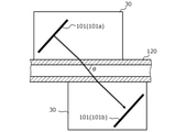
- FIG. 2 is a cross-sectional view showing an example of installing an oscillator in a pipe.
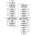
- FIG. 3 is a flowchart showing a flow of measurement operation of the propagation time measuring device according to the first embodiment.
- 4A is a diagram showing an example of a transmission signal
- FIG. 4B is a diagram showing an example of an acoustic signal based on the transmission signal of FIG. 4A
- FIG. 4C is a diagram showing an example of a reception signal
- FIG. 4D is a diagram showing a mutual. It is a figure which shows the example of the correlation function.
- FIG. 5A is a diagram showing an example of a cross-correlation function
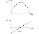
- FIG. 5B is a diagram showing an example of the Hilbert transform.
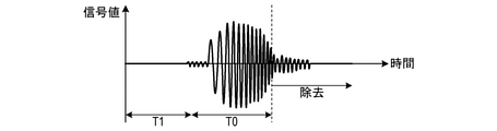
- FIG. 6 is a diagram showing the removal of reverberation in the first embodiment.
- FIG. 7 is a flowchart showing a flow of measurement operation of the propagation time measuring device according to the second embodiment.
- FIG. 8 is a diagram showing the removal of reverberation in the second embodiment.
- FIG. 9 is a flowchart showing a flow of measurement operation of the propagation time measuring device according to the third embodiment.
- FIG. 10 is a diagram showing the removal of reverberation in the third embodiment.
- FIG. 11 is a flowchart showing a flow of measurement operation of the propagation time measuring device according to the fourth embodiment.
- FIG. 12 is a diagram showing the removal of reverberation in the fourth embodiment.
- the propagation time measuring device 1 includes two or more oscillators 101, receives an acoustic signal transmitted from one of the oscillators (for example, 101a) by another oscillator (for example, 101b), and receives the acoustic signal between the two oscillators.
- the time (propagation time) required for the acoustic signal to propagate along the path of is obtained. Since the oscillators 101 are arranged at different positions with respect to the pipe 120, the acoustic signal propagating between the two oscillators 101 passes (crosses) the inside of the pipe 120.
- the propagation time of the acoustic signal is not constant and changes depending on the state of the fluid 121 flowing in the pipe 120 (for example, the flow velocity, the flow rate, the presence of bubbles or foreign matter, etc.). Therefore, by using the propagation time measured by the propagation time measuring device 1, the state of the fluid 121 in the pipe 120 can be measured non-destructively.
- the fluid 121 may be a liquid or a gas as long as it is a substance capable of propagating an acoustic signal.
- the acoustic signal is typically ultrasonic, but may include sound waves in the audible range.
- the propagation time measuring device 1 uses cross-correlation analysis to calculate the propagation time. For example, when the driving electric signal given to the transmitter 101 on the transmitting side is called a "transmission signal" and the electric signal output from the oscillator 101 on the receiving side is called a “received signal", the propagation time measuring device 1 transmits. Compute the cross-correlation function between the signal and the received signal. Then, the propagation time measuring device 1 obtains a lag (time delay) of the received signal with respect to the transmitted signal based on the maximum peak position of the cross-correlation function. This lag corresponds to the propagation time of the acoustic signal from the oscillator 101 on the transmitting side to the oscillator 101 on the receiving side.
- the signal waveform of the transmitted signal is sufficiently preserved in the received signal, a clear peak appears in the cross-correlation function, so that the lag (that is, propagation time) between the two signals can be accurately obtained. ..
- the received signal includes reverberation. If the received signal contains reverberation, the reverberation becomes noise. Therefore, in the cross-correlation function, a peak appears at a time position different from the actual propagation time, and the propagation time cannot be obtained accurately. .. As a result, it is not possible to accurately determine the flow velocity and flow rate of the fluid 121 flowing through the pipe 120.
- the propagation time measuring device 1 removes the reverberation from the received signal, and obtains the propagation time using the received signal after removing the reverberation. Specifically, the propagation time measuring device 1 removes the reverberation by any of the following methods 1 to 3.
- the removal of the reverberation may be a process of excluding the signal value of the reverberation from the cross-correlation analysis (calculation of the cross-correlation function), for example, a process of reducing (cutting) the signal value corresponding to the reverberation to zero. Alternatively, it may be a process that makes the reverberation signal value distinguishable from other signal values.
- Method 1 In the method 1, the propagation time measuring device 1 obtains the propagation time by cross-correlation analysis between the transmitted signal and the received signal before removing the reverberation, and removes the signal after the timing based on the obtained propagation time as the reverberation. do. Then, the propagation time measuring device 1 obtains the propagation time again by the cross-correlation analysis between the transmitted signal and the received signal after removing the reverberation.
- the reverberation contained in the received signal affects the required propagation time. Therefore, the timing at which the reverberation occurs can be accurately obtained based on the propagation time obtained by using the received signal before the reverberation is removed.
- the signal after the timing so determined is removed from the received signal as reverberation, and the propagation time is obtained again using the received signal after the reverberation is removed.
- the reverberation can be removed accurately, the correct peak (the peak at the position corresponding to the actual propagation time) can be detected accurately from the cross-correlation function, and the propagation time can be obtained accurately.
- the propagation time measuring device 1 approximately obtains an envelope of the waveform of the received signal from the received signal before removing the reverberation, determines a threshold value based on the obtained envelope, and determines the determined threshold value.
- the signals after the timing at which the signal values converge are removed as reverberations.
- the waveform of the received signal draws a relatively large envelope. And the signal value of reverberation is relatively small. Therefore, it is possible to accurately determine the timing at which reverberation occurs based on the envelope.
- the envelope is approximately obtained from the received signal, and the signal after the timing at which the signal value converges below the threshold value based on the envelope is removed from the received signal as reverberation. Then, the propagation time is obtained using the received signal after the reverberation is removed. By doing so, the reverberation can be removed with high accuracy, the correct peak can be detected with high accuracy from the cross-correlation function, and the propagation time can be obtained with high accuracy.
- the propagation time measuring device 1 uses the signal after the timing at which the signal value converges to a predetermined number of peaks or less from the larger side among the plurality of peaks indicated by the received signal before the reverberation is removed as the reverberation. Remove.
- the received signal shows multiple peaks that gradually increase and then gradually decrease. And the signal value of reverberation is relatively small. Therefore, it is possible to accurately determine the timing at which reverberation occurs based on a plurality of peaks.
- the predetermined number of peaks from the larger side among the plurality of peaks is set as the threshold value, and the signal after the timing at which the signal value converges below the threshold value is removed as the reverberation from the received signal, and the reverberation is removed.
- the propagation time is calculated using the received signal of. By doing so, the reverberation can be removed with high accuracy, the correct peak can be detected with high accuracy from the cross-correlation function, and the propagation time can be obtained with high accuracy.
- any of the methods 1 to 3 since unnecessary signal values (reverberation signal values) are not used for the calculation of the propagation time (specifically, the calculation of the cross-correlation function), the processing time required for the calculation of the propagation time is calculated. It can also be shortened or the power consumption required to calculate the propagation time can be reduced.
- FIG. 1 is a block diagram schematically showing the configuration of the propagation time measuring device 1
- FIG. 2 is a cross-sectional view showing an example of installing an oscillator in a pipe.
- the propagation time measuring device 1 of the present embodiment is a device for measuring the flow velocity and the flow rate of the fluid 121 flowing in the pipe 120 in a non-destructive manner, and is also referred to as an ultrasonic flow meter or an ultrasonic flow sensor.
- the propagation time measuring device 1 has a device main body 100 and a plurality of oscillators 101.
- a cable is connected between the apparatus main body 100 and each oscillator 101.
- two oscillators 101 a first oscillator 101a arranged on the upstream side in the longitudinal direction of the pipe 120 and a second oscillator 101b arranged on the downstream side of the first oscillator 101a.
- first oscillator 101a and second oscillator 101b
- the notation is simply "oscillator 101".
- the number of oscillators 101 is not limited to two, and three or more oscillators 101 may be provided.
- the oscillator 101 is a device that mutually converts an electric signal and an acoustic signal, and is also called a transducer.
- the oscillator 101 for example, a piezoelectric element that mutually converts voltage and force by the piezo effect can be used.
- each oscillator 101 is embedded in a clamp 30 made of resin.
- the two oscillators 101a and 101b face each other across the pipe 120, and the straight line connecting the two oscillators 101a and 101b forms a predetermined angle ⁇ with respect to the axis of the pipe 120.
- the oscillators 101a and 101b are installed.
- the oscillator 101 can be easily attached to the existing pipe 120 (and without modifying the pipe 120) at an appropriate position.
- the angle ⁇ is called the propagation angle of the acoustic signal.
- the propagation angle ⁇ is arbitrary, but when the propagation time difference method described later is used, it may be set in the range of 0 degrees ⁇ ⁇ 90 degrees, preferably 20 degrees ⁇ ⁇ 60 degrees.
- the device main body 100 has a control circuit 102, a D / A converter 103, an A / D converter 104, a switch 105, and an output device 106 as main configurations.
- the control circuit 102 is a circuit that controls each part of the propagation time measuring device 1, performs signal processing, arithmetic processing, and the like.
- the D / A converter 103 performs D / A conversion and signal amplification based on the transmission signal (digital data) input from the control circuit 102, and transmits a transmission signal (analog signal) of a predetermined voltage to the transducer 101. It is a circuit to output.
- the A / D converter 104 is a circuit that performs A / D conversion of a received signal (analog signal) input from the vibrator 101 at a predetermined sampling cycle and outputs the received signal (digital data) to the control circuit 102.
- the switch 105 is a switch that switches the connection relationship between the D / A converter 103 and the A / D converter 104 and the first oscillator 101a and the second oscillator 101b.
- the oscillator 101 connected to the D / A converter 103 is the transmitting side
- the oscillator 101 connected to the A / D converter 104 is the receiving side.
- the output device 106 is a device that outputs information such as the results of signal processing and arithmetic processing by the control circuit 102, and is, for example, a display device.
- the device main body 100 is provided with an input unit (for example, a button, a touch panel, etc.) for the user to operate, or a communication circuit (for example, a WiFi module) for transmitting information to an external device (for example, an external computer or a server). Etc.) may be provided.
- the control circuit 102 includes a transmission signal generation unit 110, a signal processing unit 111, and a storage unit 112.
- the transmission signal generation unit 110 has a function of generating data of a transmission signal used for measurement and outputting it to the D / A converter 103.
- the signal processing unit 111 has a function of calculating the propagation time of the acoustic signal based on the transmission signal and the reception signal, and further calculating the flow velocity and / or the flow rate of the fluid from the propagation time.
- the signal processing unit 111 also has a function of removing reverberation from the received signal. In the present embodiment, the signal processing unit 111 removes the reverberation by the method 1 described above.
- the storage unit 112 stores waveform data that defines the waveform of the transmission signal.
- the transmission signal generation unit 110 reads the waveform data from the storage unit 112 and generates the transmission signal data.
- the control circuit 102 may be configured by, for example, a computer having a CPU (processor), RAM, a non-volatile storage device (for example, ROM, flash memory, hard disk, etc.), I / O, and the like.
- the CPU expands the program stored in the storage device into the RAM and executes the program, thereby providing the functions of the transmission signal generation unit 110 and the signal processing unit 111.
- the form of the computer does not matter. For example, it may be a personal computer, an embedded computer, a smartphone, a tablet terminal, or the like.
- all or part of the functions provided by the control circuit 102 may be configured by a circuit such as an ASIC or FPGA.
- the control circuit 102 may perform the processing described later in cooperation with another computer by using the technology of distributed computing or cloud computing.
- the material, size, and shape of the pipe 120 do not matter.
- metal piping or resin piping may be used.
- the size of the pipe 120 may be a standard size defined by JIS or ANSI, or may be a unique size. Since the method of the present embodiment has an advantage that the measurement of a minute flow rate can be performed with high accuracy, a 1/8 inch pipe (outer diameter: 3.18 mm, inner diameter: 1.59 mm), 1/4 inch pipe It is particularly preferably applicable to the measurement of small pipes (outer diameter: 6.35 mm, inner diameter: 3.97 mm), 1/2 inch pipes (outer diameter: 12.70 mm, inner diameter: 9.53 mm). Further, the pipe is not limited to a straight pipe, but may be a pipe having a bent portion, a curved pipe, or the like, and the cross-sectional shape of the pipe is arbitrary.
- step S100 the transmission signal generation unit 110 of the control circuit 102 reads the waveform data of the transmission signal from the storage unit 112.
- step S101 the control circuit 102 controls the switch 105, connects the D / A converter 103 to the first oscillator 101a, and connects the A / D converter 104 to the second oscillator 101b.
- the first oscillator 101a becomes the transmitting side and the second oscillator 101b becomes the receiving side.
- step S102 the transmission signal generation unit 110 generates a transmission signal based on the waveform data read in step S100, and outputs the transmission signal to the D / A converter 103. Further, this transmission signal is temporarily stored in RAM (work memory) for use in the cross-correlation analysis in the subsequent stage.
- step S103 the transmission signal D / A converted and amplified by the D / A converter 103 is input to the first oscillator 101a, and the acoustic signal based on the transmission signal is transmitted from the first oscillator 101a.
- FIG. 4A is an example of a transmission signal, the horizontal axis is time, and the vertical axis is a signal value.
- FIG. 4B is an example of an acoustic signal based on the transmission signal of FIG. 4A, where the horizontal axis is time and the vertical axis is sound pressure.
- the amplitude of the transmission signal is constant, the amplitude of the acoustic signal is not constant because of the frequency characteristics of the vibrator.
- the acoustic signal reaches the second oscillator 101b via the clamp 30, the pipe 120, and the fluid 121.
- step S104 the second oscillator 101b converts the received acoustic signal into a received signal and outputs it to the A / D converter 104.
- FIG. 4C is an example of a received signal, the horizontal axis is time, and the vertical axis is a signal value. In FIG. 4C, the vertical axis is enlarged with respect to FIG. 4A. Since the acoustic signal is attenuated in the propagation process, the amplitude (voltage) of the received signal is on the order of 1/100 to 1/1000 of that of the transmitted signal. For example, the amplitude of the transmitted signal in FIG. 4A is about 30 V, whereas the amplitude of the received signal in FIG. 4C is about 10 mV. Further, as shown in FIG. 4C, various noises including reverberation are carried in the received signal.
- the received signal A / D converted by the A / D converter 104 is taken into the control circuit 102 and temporarily stored in the RAM (work memory).
- step S105 the signal processing unit 111 reads the transmission signal and the reception signal from the RAM, and calculates the cross-correlation function between the two signals.
- FIG. 4D is an example of the cross-correlation function, and only the vicinity of the maximum peak is enlarged and shown.
- the horizontal axis is time (time shift amount), and the vertical axis is the value of cross-correlation standardized so that the height of the maximum peak is 1. Since the cross-correlation function is a known technique, detailed description thereof is omitted here.
- step S106 the signal processing unit 111 obtains the time position of the maximum peak (peak) in the cross-correlation function calculated in step S105 as the propagation time T1 of the acoustic signal from the first oscillator 101a to the second oscillator 101b. ..
- the propagation time T1 deviates from the actual propagation time due to the influence of the reverberation of the received signal and the like.
- the cross-correlation function calculated in step S105 is composed of discrete data. Therefore, as shown in FIG. 5A, the points where the data of the cross-correlation function are obtained (points indicated by black circles) and the positions of the peaks (vertices) do not always match. Therefore, in step S106, the signal processing unit 111 estimates the position of the maximum peak after approximately obtaining the shape of the maximum peak and the waveform around it (maximum peak waveform) from the discrete data of the cross-correlation function. good. For example, as shown in FIG. 5B, the signal processing unit 111 may convert the data near the maximum peak in the cross-correlation function into phase data by the Hilbert transform.
- the converted data may be linearly approximated, and the zero crossing point (position where the phase becomes zero) of the approximated straight line may be regarded as the position of the maximum peak.
- the signal processing unit 111 may estimate the shape of the maximum peak waveform by interpolating the data near the maximum peak of the cross-correlation function by polynomial approximation, and determine the position of the peak. By such processing, the position where the cross-correlation is maximized, that is, the propagation time of the acoustic signal can be obtained with a resolution higher than the sampling period of the A / D conversion.
- step S107 the signal processing unit 111 removes the signal after the timing based on the propagation time T1 obtained in step S106 from the received signal read in step S105 as reverberation.
- the oscillator on the receiving side is considered to receive an acoustic signal having the same time length as the transmission signal from the timing when the propagation time has elapsed, and among the received signals, the signal after the reception of the acoustic signal is completed. Is considered to be a reverberation. Therefore, as shown in FIG. 6, the signal processing unit 111 is a signal after the timing when the total time of the propagation time T1 and the time length T0 of the transmission signal has elapsed from the timing when the transmission signal is input to the first oscillator 101a. Is removed from the received signal as a reverberation. By doing so, the reverberation can be removed with high accuracy.
- step S108 the signal processing unit 111 calculates a cross-correlation function between the transmission signal read in step S105 and the received signal after removing the reverberation in step S107.
- step S109 the signal processing unit 111 sets the time position of the maximum peak (peak) in the cross-correlation function calculated in step S108 as the propagation time T1'of the acoustic signal from the first oscillator 101a to the second oscillator 101b. demand.
- the propagation time T1' which is close to the actual propagation time is obtained.
- step S110 the control circuit 102 controls the switch 105, connects the D / A converter 103 to the second oscillator 101b, and connects the A / D converter 104 to the first oscillator 101a. That is, the oscillators on the transmitting side and the receiving side are exchanged. Subsequent processes of steps S111 to S118 are the same as the processes of steps S102 to S109 (however, "first oscillator 101a” is read as “second oscillator 101b", and "second oscillator 101b" is ".
- step S115 the propagation time T2 of the acoustic signal from the second oscillator 101b to the first oscillator 101a is obtained from the cross-correlation function based on the received signal before the reverberation is removed.
- step S118 the propagation time T2'of the acoustic signal from the second oscillator 101b to the first oscillator 101a is obtained from the cross-correlation function based on the received signal after the reverberation is removed.
- the propagation time T1'of the acoustic signal from the first oscillator 101a to the second oscillator 101b and the propagation time T2' of the acoustic signal from the second oscillator 101b to the first oscillator 101a are obtained. Will be.
- a time difference is generated between the propagation time T1'and the propagation time T2' depending on the flow velocity of the fluid 121. Therefore, the flow velocity and the flow rate of the fluid 121 can be calculated by using the propagation time T1'and the propagation time T2'. Since the reverberation is removed and the propagation time T1'and the propagation time T2'are accurately obtained, the flow velocity and the flow rate of the fluid 121 can also be accurately obtained.
- step S119 the signal processing unit 111 obtains the flow velocity V of the fluid 121 by the following formula.
- V is the flow velocity of the fluid
- L is the propagation path length inside the pipe
- ⁇ is the propagation angle
- Tab is the propagation time T1'from the oscillator on the upstream side to the oscillator on the downstream side
- Tba is the oscillator on the downstream side.
- Propagation time T2'and To from to the oscillator on the upstream side are the propagation times of parts other than the fluid.
- the propagation time To of the portion other than the fluid is, for example, the time during which the acoustic signal propagates through the clamp 30 and the portion of the pipe 120, and if the specifications of the pipe 120 (inner diameter, outer diameter, material, etc.) are known, an experiment is performed. Alternatively, it can be obtained in advance by simulation.
- step S120 the signal processing unit 111 obtains the flow rate Q of the fluid by the following formula.
- Q is the flow rate of the fluid
- V is the flow velocity of the fluid
- A is the cross-sectional area inside the pipe. It is assumed that the cross-sectional area A is known.
- step S121 the signal processing unit 111 outputs the processing result (for example, propagation time, flow velocity, flow rate, etc.) to the output device 106.
- the processing result for example, propagation time, flow velocity, flow rate, etc.
- the timing at which the reverberation occurs can be accurately obtained based on the propagation time obtained by using the received signal before the reverberation is removed. Then, the signal after the timing so determined is removed from the received signal as reverberation, and the propagation time is obtained again using the received signal after the reverberation is removed. By doing so, the reverberation can be removed with high accuracy, and the propagation time can be obtained with high accuracy. Therefore, it can be applied to situations where high accuracy is required, such as measurement of a minute flow rate. Furthermore, since unnecessary signal values (reverberation signal values) are not used in the calculation of the propagation time, the processing time required for the calculation of the propagation time can be shortened, and the power consumption required for the calculation of the propagation time can be reduced. can.
- the propagation time measuring device 1 removes reverberation by the method 2 described above. Since the basic configuration is the same as that of the first embodiment, the components different from those of the first embodiment will be mainly described below.
- FIG. 7 is a flowchart showing the flow of the measurement operation of the propagation time measuring device 1 according to the second embodiment.
- the same step numbers are assigned to the same processes as in the flowchart of the first embodiment (FIG. 3).
- steps S100 to S104 is the same as that of the first embodiment.
- the signal processing unit 111 reads the received signal from the RAM, and as shown in FIG. 8, approximately obtains the envelope of the waveform of the received signal. Since the envelope can be obtained by using a known technique, detailed description thereof is omitted here.
- step S201 the signal processing unit 111 determines a value obtained by reducing the peak of the envelope obtained in step S200 by a predetermined magnification as a threshold value, and the signal value is equal to or less than the determined threshold value from the received signal read in step S200.
- the predetermined magnification is not particularly limited, but is, for example, 1/2 times.
- step S202 the signal processing unit 111 removes the signal after the time Ta detected in step S201 from the received signal read in step S200 as reverberation.
- step S203 the signal processing unit 111 reads the transmission signal from the RAM and calculates the cross-correlation function between the read transmission signal and the received signal after removing the reverberation in step S202.
- step S204 the signal processing unit 111 sets the time position of the maximum peak (peak) in the cross-correlation function calculated in step S203 as the propagation time T1'of the acoustic signal from the first oscillator 101a to the second oscillator 101b. demand.
- the propagation time T1' which is close to the actual propagation time is obtained.
- steps S110 to S113 is the same as that of the first embodiment.
- the processing of steps S210 to S214 is the same as the processing of steps S200 to S204 (however, “first oscillator 101a” is read as “second oscillator 101b", and “second oscillator 101b” is “first oscillator 101b”. It should be read as "oscillator 101a”.)
- step S211 the signal processing unit 111 determines a value obtained by reducing the peak of the envelope obtained in step S210 by a predetermined magnification as a threshold value, and the signal value is equal to or less than the determined threshold value from the received signal read in step S210. The time Tb until convergence is detected.
- step S214 the propagation time T2'of the acoustic signal from the second oscillator 101b to the first oscillator 101a is obtained from the cross-correlation function based on the received signal after the reverberation is removed.
- the processing of steps S119 to S121 is the same as that of the first embodiment.
- the envelope of the waveform of the received signal is obtained from the received signal before the reverberation is removed, and the peak of the obtained envelope is reduced by a predetermined magnification. Is determined as the threshold. Then, from the received signal, the signal after the timing at which the signal value converges to the determined threshold value or less is removed as reverberation, and the propagation time is obtained using the received signal after the reverberation is removed.
- the reverberation can be removed with high accuracy, and the propagation time can be obtained with high accuracy. Therefore, it can be applied to situations where high accuracy is required, such as measurement of a minute flow rate.
- unnecessary signal values reverberation signal values
- the processing time required for the calculation of the propagation time can be shortened, and the power consumption required for the calculation of the propagation time can be reduced. can.
- the propagation time measuring device 1 according to the third embodiment of the present invention removes reverberation by the method 2 described above.
- the specific method for removing the reverberation is different from that of the second embodiment. Since the basic configuration is the same as that of the above embodiment, the components different from the above embodiment will be mainly described below.
- FIG. 9 is a flowchart showing the flow of the measurement operation of the propagation time measuring device 1 according to the third embodiment.
- the same step numbers are assigned to the same processes as in the flowchart of the second embodiment (FIG. 7).
- the processing of steps S100 to S104 and step S200 is the same as that of the second embodiment.
- the envelope data obtained in step S200 is discrete data.
- the time interval of the plurality of discrete values constituting the envelope is not particularly limited, but is equivalent to, for example, the time interval of the plurality of peaks indicated by the received signal, specifically, the same as the time interval of the plurality of peaks indicated by the transmitted signal. ..
- step S301 the signal processing unit 111 determines a predetermined number of discrete values from the larger side as a threshold value among the plurality of discrete values constituting the envelope obtained in step S200. Then, the signal processing unit 111 detects the time Ta from the received signal read in step S200 until the signal value converges to the determined threshold value or less.
- the predetermined number is not particularly limited, but is, for example, 10.
- step S302 the signal processing unit 111 removes the signal after the time Ta detected in step S301 from the received signal read in step S200 as reverberation.
- step S303 the signal processing unit 111 reads the transmission signal from the RAM and calculates the cross-correlation function between the read transmission signal and the received signal after removing the reverberation in step S302.
- step S304 the signal processing unit 111 sets the time position of the maximum peak (peak) in the cross-correlation function calculated in step S303 as the propagation time T1'of the acoustic signal from the first oscillator 101a to the second oscillator 101b. demand.
- the propagation time T1' which is close to the actual propagation time is obtained.
- step S311 the signal processing unit 111 determines a predetermined number of discrete values from the larger side as a threshold value among the plurality of discrete values constituting the envelope obtained in step S210. Then, the signal processing unit 111 detects the time Tb from the received signal read in step S210 until the signal value converges to the determined threshold value or less.
- step S314 the propagation time T2'of the acoustic signal from the second oscillator 101b to the first oscillator 101a is obtained from the cross-correlation function based on the received signal after the reverberation is removed.
- the processing of steps S119 to S121 is the same as that of the second embodiment.
- the envelope of the waveform of the received signal is obtained from the received signal before the reverberation is removed, and among the plurality of discrete values constituting the obtained envelope, the envelope is obtained.
- the predetermined number of discrete values from the larger side is determined as the threshold value.
- the signal after the timing at which the signal value converges to the determined threshold value or less is removed as reverberation, and the propagation time is obtained using the received signal after the reverberation is removed.
- the reverberation can be removed with high accuracy, and the propagation time can be obtained with high accuracy. Therefore, it can be applied to situations where high accuracy is required, such as measurement of a minute flow rate.
- unnecessary signal values reverberation signal values
- the processing time required for the calculation of the propagation time can be shortened, and the power consumption required for the calculation of the propagation time can be reduced. can.
- the propagation time measuring device 1 according to the fourth embodiment of the present invention removes reverberation by the method 3 described above. Since the basic configuration is the same as that of the above embodiment, the components different from the above embodiment will be mainly described below.
- FIG. 11 is a flowchart showing the flow of the measurement operation of the propagation time measuring device 1 according to the fourth embodiment.
- the same step numbers are assigned to the same processes as in the flowchart of the first embodiment (FIG. 3).
- steps S100 to S104 is the same as that of the first embodiment.
- the signal processing unit 111 reads the received signal from the RAM, and determines the predetermined number of peaks from the larger side among the plurality of peaks indicated by the received signal as the threshold value. Then, the signal processing unit 111 detects the time Ta from the received signal until the signal value converges to the determined threshold value or less.
- the predetermined number is not particularly limited, but is, for example, 10.
- step S401 the signal processing unit 111 removes the signal after the time Ta detected in step S400 from the received signal read in step S400 as reverberation.
- step S402 the signal processing unit 111 reads the transmission signal from the RAM and calculates the cross-correlation function between the read transmission signal and the received signal after removing the reverberation in step S401.
- step S403 the signal processing unit 111 sets the time position of the maximum peak (peak) in the cross-correlation function calculated in step S402 as the propagation time T1'of the acoustic signal from the first oscillator 101a to the second oscillator 101b. demand.
- the propagation time T1' which is close to the actual propagation time is obtained.
- steps S110 to S113 is the same as that of the first embodiment.
- the processing of steps S410 to S413 is the same as the processing of steps S400 to S403 (however, “first oscillator 101a” is read as “second oscillator 101b", and “second oscillator 101b” is “first oscillator 101b”. It should be read as "oscillator 101a”.)
- the signal processing unit 111 reads the received signal (received signal acquired in step S113) from the RAM, and among the plurality of peaks indicated by the received signal, the predetermined number of peaks from the larger side is set as a threshold value. decide.
- the signal processing unit 111 detects the time Tb from the received signal until the signal value converges to the determined threshold value or less.
- the propagation time T2'of the acoustic signal from the second oscillator 101b to the first oscillator 101a is obtained from the cross-correlation function based on the received signal after the reverberation is removed.
- the processing of steps S119 to S121 is the same as that of the first embodiment.
- the predetermined number of peaks from the larger side is determined as the threshold value. Then, from the received signal, the signal after the timing at which the signal value converges to the determined threshold value or less is removed as reverberation, and the propagation time is obtained using the received signal after the reverberation is removed.
- the reverberation can be removed with high accuracy, and the propagation time can be obtained with high accuracy. Therefore, it can be applied to situations where high accuracy is required, such as measurement of a minute flow rate.
- the processing time required for the calculation of the propagation time can be shortened, and the power consumption required for the calculation of the propagation time can be reduced. can.
- the peak to be shown in the received signal may not be shown. In such a case, it can be expected that more accurate propagation time can be obtained in the first to third embodiments, but processing such as obtaining a provisional propagation time and obtaining an envelope is increased.
- the above embodiment merely illustrates the configuration of the present invention.
- the present invention is not limited to the above-mentioned specific form, and various modifications can be made within the scope of its technical idea.
- the propagation time measuring device may simply perform a process of measuring the propagation time (at least one of the propagation time T1'and the propagation time T2'). Further, if the propagation time is simply measured, the propagation angle ⁇ may be 90 degrees.
- the clamp-on type device that can be attached so as to sandwich the pipe is exemplified, but a pipe built-in type device configuration may be adopted.
- the number of oscillators may be three or more, and the oscillator pair used for propagating the acoustic signal from the upstream side to the downstream side and the oscillator pair used for propagating the acoustic signal from the downstream side to the upstream side are separated. May be good.
- the oscillator on the transmitting side and the oscillator on the receiving side may be arranged at different positions with respect to the pipe, may not be arranged so as to face each other across the pipe, and may be arranged in different longitudinal directions of the pipe. It does not have to be placed in position.
- the storage unit 112 may store information regarding the timing at which reverberation occurs in advance, and the signal processing unit 111 may remove the reverberation based on the information stored by the storage unit 112.
- the information regarding the timing at which the reverberation occurs may be information indicating the timing itself (time T1 + T0 of the first embodiment, time T2 + T0, time Ta, Tb of the second to fourth embodiments, etc.), and so on. It does not have to be.
- the information regarding the timing at which the reverberation occurs may be information indicating the propagation time (propagation time T1 or propagation time T2 of the first embodiment) obtained by using the received signal including the reverberation.
- the information regarding the timing at which the reverberation occurs may be information indicating a threshold value (threshold value used in the second to fourth embodiments) based on the envelope or a plurality of peaks.
- Information regarding the timing at which reverberation occurs is obtained, for example, in the pre-measurement by the same method as that described in the first to fourth embodiments. Then, in this measurement, the signal processing unit 111 reads the information from the storage unit 112 instead of requesting the information regarding the timing at which the reverberation occurs. For example, when the propagation time T1'is obtained by the method of the first embodiment, the processes of steps S101 to S106 of FIG. 3 are performed in the pre-measurement, and the signal processing unit 111 stores the obtained propagation time T1. Store in 112. Then, in this measurement, the processes of steps S101 to S104 are performed, the signal processing unit 111 reads the propagation time T1 from the storage unit 112, and the processes of steps S107 to S109 are performed.
- the acoustic signal may be transmitted and received a plurality of times by the oscillator pair. Then, the signal processing unit 111 may acquire information regarding the timing at which reverberation occurs by using a plurality of received signals obtained by a plurality of transmissions and receptions. Since the resolution is apparently improved by synthesizing a plurality of received signals, it is possible to obtain the timing at which reverberation occurs more accurately by using a plurality of received signals. For example, the propagation time T1, the propagation time T2, the envelope, the peak of the received signal, and the like can be obtained more accurately. As a result, the reverberation can be removed more accurately, and the propagation time can be obtained more accurately.
- the time Ta for removing the reverberation from the received signal (corresponding to the acoustic signal from the first oscillator 101a to the second oscillator 101b) obtained by the second oscillator 101b.
- an example of individually determining the time Tb for removing the reverberation from the received signal (corresponding to the acoustic signal from the second oscillator 101b to the first oscillator 101a) obtained by the first oscillator 101a will be described.
- only one of the times Ta and Tb may be detected, and the detected time may be used as the other of the times Ta and Tb. As a result, the processing load and processing time can be reduced.
- steps S210 and S211 in FIG. 7 envelope detection, threshold value determination, and time Tb detection
- steps S210 and S311 envelope detection, threshold value determination, and time Tb detection
- steps S410 of FIG. 11 threshold value determination and time Tb detection
- one of the propagation times T1 and T2 may be used as the other of the propagation times T1 and T2.
- one of the two threshold values for determining the two time Tas and Tb may be used as the other of the two threshold values.
- ⁇ Appendix 1> A plurality of oscillators (101a, 101b) arranged at different positions with respect to a pipe (120) through which a fluid (121) flows, and a first oscillator (101a) that converts a transmission signal as an electric signal into an acoustic signal. ) And the second oscillator (101b) that receives the acoustic signal transmitted from the first oscillator (101a) and propagates through the fluid (121) in the pipe (120) and converts it into a received signal as an electric signal.
- a propagation time measuring device (1) By cross-correlation analysis between the transmitted signal and the received signal after removing the reverberation, the propagation time of the acoustic signal from the first vibrator (101a) to the second vibrator (101b) is obtained again.
- a propagation time measuring device (1) By cross-correlation analysis between the transmitted signal and the received signal after removing the reverberation, the propagation time of the acoustic signal from the first vibrator (101a) to the second vibrator (101b) is obtained again.
- ⁇ Appendix 2> A plurality of oscillators (101a, 101b) arranged at different positions with respect to a pipe (120) through which a fluid (121) flows, and a first oscillator (101a) that converts a transmission signal as an electric signal into an acoustic signal. ) And the second oscillator (101b) that receives the acoustic signal transmitted from the first oscillator (101a) and propagates through the fluid (121) in the pipe (120) and converts it into a received signal as an electric signal.
- a propagation time measuring device (1) characterized in that a signal after the timing at which the signal value converges is removed as the reverberation.
- ⁇ Appendix 3> A plurality of oscillators (101a, 101b) arranged at different positions with respect to a pipe (120) through which a fluid (121) flows, and a first oscillator (101a) that converts a transmission signal as an electric signal into an acoustic signal. ) And the second oscillator (101b) that receives the acoustic signal transmitted from the first oscillator (101a) and propagates through the fluid (121) in the pipe (120) and converts it into a received signal as an electric signal.
- the signal processing unit (111) for obtaining Equipped with The signal processing unit (111) uses as the reverberation a signal after the timing at which the signal value converges to a predetermined number of peaks or less from the larger side among the plurality of peaks indicated by the received signal before the reverberation is removed.
- Propagation time measuring device 30 Clamp 100: Device main body 101: Oscillator 101a: First oscillator 101b: Second oscillator 102: Control circuit 103: D / A converter 104: A / D converter 105: Switching Device 106: Output device 110: Transmission signal generation unit 111: Signal processing unit 112: Storage unit 120: Piping 121: Fluid
Landscapes
- Physics & Mathematics (AREA)
- Electromagnetism (AREA)
- Fluid Mechanics (AREA)
- General Physics & Mathematics (AREA)
- Measuring Volume Flow (AREA)
- Measurement Of Velocity Or Position Using Acoustic Or Ultrasonic Waves (AREA)
Abstract
Description
図1を参照して、伝搬時間測定装置の適用例を説明する。
方法1では、伝搬時間測定装置1は、送信信号と残響を除去する前の受信信号とのあいだの相互相関解析により伝搬時間を求め、求めた伝搬時間に基づくタイミング以降の信号を、残響として除去する。そして、伝搬時間測定装置1は、送信信号と残響を除去した後の受信信号とのあいだの相互相関解析により伝搬時間を再び求める。
方法2では、伝搬時間測定装置1は、残響を除去する前の受信信号から、当該受信信号の波形の包絡線を近似的に求め、求めた包絡線に基づいて閾値を決定し、決定した閾値以下に信号値が収束するタイミング以降の信号を、残響として除去する。
方法3では、伝搬時間測定装置1は、残響を除去する前の受信信号が示す複数のピークのうち、大きい側から所定数番目のピーク以下に信号値が収束するタイミング以降の信号を、残響として除去する。
(装置構成)
図1及び図2を参照して、伝搬時間測定装置1の具体的な構成を説明する。図1は、伝搬時間測定装置1の構成を模式的に示すブロック図であり、図2は、配管への振動子の設置例を示す断面図である。本実施形態の伝搬時間測定装置1は、配管120内を流れる流体121の流速及び流量を非破壊で計測するための装置であり、超音波流量計又は超音波流量センサとも称される。
図3のフローチャートに沿って、伝搬時間測定装置1の測定動作の流れを説明する。


以上述べた本実施形態の構成によれば、残響が除去される前の受信信号を用いて求められた伝搬時間に基づき、残響が発生するタイミングが精度よく求められる。そして、受信信号から、そのように求められたタイミング以降の信号が残響として除去され、残響が除去された後の受信信号を用いて伝搬時間が再び求められる。こうすることで、残響を精度よく除去することができ、伝搬時間を精度よく求めることができる。よって、微少流量の測定など、高い精度が要求される場面への適用も可能である。さらに、不要な信号値(残響の信号値)が伝搬時間の計算に使用されないため、伝搬時間の計算に要する処理時間を短縮したり、伝搬時間の計算に要する消費電力を低減したりすることができる。
本発明の第2実施形態に係る伝搬時間測定装置1は、上述した方法2で残響を除去する。基本構成は第1実施形態と同様であるため、以下では、第1実施形態と異なる構成部分を中心に説明する。
本発明の第3実施形態に係る伝搬時間測定装置1は、上述した方法2で残響を除去する。但し、残響を除去する具体的な方法は、第2実施形態と異なる。基本構成は上記実施形態と同様であるため、以下では、上記実施形態と異なる構成部分を中心に説明する。
本発明の第4実施形態に係る伝搬時間測定装置1は、上述した方法3で残響を除去する。基本構成は上記実施形態と同様であるため、以下では、上記実施形態と異なる構成部分を中心に説明する。
上記実施形態は、本発明の構成を例示的に説明するものに過ぎない。本発明は上記の具体的な形態には限定されることはなく、その技術的思想の範囲内で種々の変形が可能である。例えば、上記実施形態の装置では、音響信号の伝搬時間を測定した後、その伝搬時間の測定値を利用して流体の流速及び流量を計算したが、流速及び流量の計算は必須ではない。伝搬時間測定装置は、単に伝搬時間(伝搬時間T1’と伝搬時間T2’の少なくとも一方)を測定する処理を行うだけでもよい。また、単に伝搬時間を測定するだけであれば、伝搬角度θは90度でもよい。また、上記実施形態では、配管を挟み込むように取り付け可能なクランプオン型の装置を例示したが、配管組み込み型の装置構成を採用してもよい。また、振動子の数は3つ以上でもよく、上流側から下流側への音響信号の伝搬に用いる振動子対と、下流側から上流側への音響信号の伝搬に用いる振動子対を分けてもよい。送信側の振動子と受信側の振動子とは、配管に対して互いに異なる位置に配置されればよく、配管を挟んで対向するように配置されなくてもよいし、配管の長手方向の異なる位置に配置されなくてもよい。
流体(121)を流す配管(120)に対し互いに異なる位置に配置される複数の振動子(101a、101b)であって、電気信号としての送信信号を音響信号に変換する第1振動子(101a)と、前記第1振動子(101a)から送信されて前記配管(120)内の流体(121)を伝搬した前記音響信号を受信し電気信号としての受信信号に変換する第2振動子(101b)とを少なくとも含む、複数の振動子(101a、101b)と、
前記受信信号から残響を除去し、前記送信信号と前記残響を除去した後の受信信号とのあいだの相互相関解析により、前記第1振動子から前記第2振動子までの前記音響信号の伝搬時間を求める信号処理部(111)と、
を備え、
前記信号処理部(111)は、
前記送信信号と前記残響を除去する前の受信信号とのあいだの相互相関解析により、前記第1振動子(101a)から前記第2振動子(101b)までの前記音響信号の伝搬時間を求め、
求めた伝搬時間に基づくタイミング以降の信号を、前記残響として除去し、
前記送信信号と前記残響を除去した後の受信信号とのあいだの相互相関解析により、前記第1振動子(101a)から前記第2振動子(101b)までの前記音響信号の伝搬時間を再び求める
ことを特徴とする伝搬時間測定装置(1)。
流体(121)を流す配管(120)に対し互いに異なる位置に配置される複数の振動子(101a、101b)であって、電気信号としての送信信号を音響信号に変換する第1振動子(101a)と、前記第1振動子(101a)から送信されて前記配管(120)内の流体(121)を伝搬した前記音響信号を受信し電気信号としての受信信号に変換する第2振動子(101b)とを少なくとも含む、複数の振動子(101a、101b)と、
前記受信信号から残響を除去し、前記送信信号と前記残響を除去した後の受信信号とのあいだの相互相関解析により、前記第1振動子から前記第2振動子までの前記音響信号の伝搬時間を求める信号処理部(111)と、
を備え、
前記信号処理部(111)は、前記残響を除去する前の受信信号から、当該受信信号の波形の包絡線を近似的に求め、前記包絡線に基づいて閾値を決定し、決定した閾値以下に信号値が収束するタイミング以降の信号を、前記残響として除去する
ことを特徴とする伝搬時間測定装置(1)。
流体(121)を流す配管(120)に対し互いに異なる位置に配置される複数の振動子(101a、101b)であって、電気信号としての送信信号を音響信号に変換する第1振動子(101a)と、前記第1振動子(101a)から送信されて前記配管(120)内の流体(121)を伝搬した前記音響信号を受信し電気信号としての受信信号に変換する第2振動子(101b)とを少なくとも含む、複数の振動子(101a、101b)と、
前記受信信号から残響を除去し、前記送信信号と前記残響を除去した後の受信信号とのあいだの相互相関解析により、前記第1振動子から前記第2振動子までの前記音響信号の伝搬時間を求める信号処理部(111)と、
を備え、
前記信号処理部(111)は、前記残響を除去する前の受信信号が示す複数のピークのうち、大きい側から所定数番目のピーク以下に信号値が収束するタイミング以降の信号を、前記残響として除去する
ことを特徴とする伝搬時間測定装置(1)。
101:振動子 101a:第1振動子 101b:第2振動子
102:制御回路 103:D/A変換器 104:A/D変換器
105:切り替え器 106:出力器
110:送信信号生成部 111:信号処理部 112:記憶部
120:配管 121:流体
Claims (12)
- 流体を流す配管に対し互いに異なる位置に配置される複数の振動子であって、電気信号としての送信信号を音響信号に変換する第1振動子と、前記第1振動子から送信されて前記配管内の流体を伝搬した前記音響信号を受信し電気信号としての受信信号に変換する第2振動子とを少なくとも含む、複数の振動子と、
前記受信信号から残響を除去し、前記送信信号と前記残響を除去した後の受信信号とのあいだの相互相関解析により、前記第1振動子から前記第2振動子までの前記音響信号の伝搬時間を求める信号処理部と、
を備え、
前記信号処理部は、
前記送信信号と前記残響を除去する前の受信信号とのあいだの相互相関解析により、前記第1振動子から前記第2振動子までの前記音響信号の伝搬時間を求め、
求めた伝搬時間に基づくタイミング以降の信号を、前記残響として除去し、
前記送信信号と前記残響を除去した後の受信信号とのあいだの相互相関解析により、前記第1振動子から前記第2振動子までの前記音響信号の伝搬時間を再び求める
ことを特徴とする伝搬時間測定装置。 - 前記タイミングは、前記第1振動子に前記送信信号を入力したタイミングから、前記送信信号と前記残響を除去する前の受信信号とのあいだの相互相関解析により求められた伝搬時間と、前記送信信号の時間長との合計時間が経過したタイミングである
ことを特徴とする請求項1に記載の伝搬時間測定装置。 - 流体を流す配管に対し互いに異なる位置に配置される複数の振動子であって、電気信号としての送信信号を音響信号に変換する第1振動子と、前記第1振動子から送信されて前記配管内の流体を伝搬した前記音響信号を受信し電気信号としての受信信号に変換する第2振動子とを少なくとも含む、複数の振動子と、
前記受信信号から残響を除去し、前記送信信号と前記残響を除去した後の受信信号とのあいだの相互相関解析により、前記第1振動子から前記第2振動子までの前記音響信号の伝搬時間を求める信号処理部と、
を備え、
前記信号処理部は、前記残響を除去する前の受信信号から、当該受信信号の波形の包絡線を近似的に求め、前記包絡線に基づいて閾値を決定し、決定した閾値以下に信号値が収束するタイミング以降の信号を、前記残響として除去する
ことを特徴とする伝搬時間測定装置。 - 前記信号処理部は、前記包絡線のピークを所定の倍率で低減した値を、前記閾値として決定する
ことを特徴とする請求項3に記載の伝搬時間測定装置。 - 前記信号処理部は、前記包絡線を構成する複数の離散値のうち、大きい側から所定数番目の離散値を、前記閾値として決定する
ことを特徴とする請求項3に記載の伝搬時間測定装置。 - 流体を流す配管に対し互いに異なる位置に配置される複数の振動子であって、電気信号としての送信信号を音響信号に変換する第1振動子と、前記第1振動子から送信されて前記配管内の流体を伝搬した前記音響信号を受信し電気信号としての受信信号に変換する第2振動子とを少なくとも含む、複数の振動子と、
前記受信信号から残響を除去し、前記送信信号と前記残響を除去した後の受信信号とのあいだの相互相関解析により、前記第1振動子から前記第2振動子までの前記音響信号の伝搬時間を求める信号処理部と、
を備え、
前記信号処理部は、前記残響を除去する前の受信信号が示す複数のピークのうち、大きい側から所定数番目のピーク以下に信号値が収束するタイミング以降の信号を、前記残響として除去する
ことを特徴とする伝搬時間測定装置。 - 前記タイミングに関する情報を予め記憶する記憶部をさらに備え、
前記信号処理部は、前記記憶部が予め記憶した前記情報に基づいて前記残響を除去する
ことを特徴とする請求項1~6のいずれか1項に記載の伝搬時間測定装置。 - 前記信号処理部は、前記第1振動子からの送信及び前記第2振動子による受信を複数回行うことによって得られた複数の受信信号を用いて、前記タイミングに関する情報を取得する
ことを特徴とする請求項1~7のいずれか1項に記載の伝搬時間測定装置。 - 前記第1振動子と前記第2振動子は、前記配管を挟んで対向するように配置される
ことを特徴とする請求項1~8のいずれか1項に記載の伝搬時間測定装置。 - 前記第1振動子と前記第2振動子は、前記配管の長手方向の異なる位置に配置される
ことを特徴とする請求項1~9のいずれか1項に記載の伝搬時間測定装置。 - 前記第2振動子に前記送信信号が入力され、前記第2振動子から送信された音響信号を受信した前記第1振動子から前記受信信号が出力されるように切り替えを行う切り替え部をさらに備え、
前記信号処理部は、さらに、前記第1振動子から出力された前記受信信号から残響を除去し、前記第2振動子に入力した前記送信信号と前記第1振動子から出力されて前記残響が除去された後の受信信号のあいだの相互相関解析により、前記第2振動子から前記第1振動子までの前記音響信号の伝搬時間を求める
ことを特徴とする請求項1~10のいずれか1項に記載の伝搬時間測定装置。 - 前記信号処理部は、前記第1振動子から前記第2振動子までの前記音響信号の伝搬時間と、前記第2振動子から前記第1振動子までの前記音響信号の伝搬時間との差に基づいて、前記配管内の流体の流速及び/又は流量を求める
ことを特徴とする請求項11に記載の伝搬時間測定装置。
Priority Applications (3)
| Application Number | Priority Date | Filing Date | Title |
|---|---|---|---|
| CN202180058825.7A CN116075698B (zh) | 2020-08-07 | 2021-07-20 | 传播时间测定装置 |
| EP21853437.8A EP4174452B1 (en) | 2020-08-07 | 2021-07-20 | Propagation time measurement device |
| US18/006,397 US12292319B2 (en) | 2020-08-07 | 2021-07-20 | Propagation time measurement device |
Applications Claiming Priority (2)
| Application Number | Priority Date | Filing Date | Title |
|---|---|---|---|
| JP2020-135276 | 2020-08-07 | ||
| JP2020135276A JP7615562B2 (ja) | 2020-08-07 | 2020-08-07 | 伝搬時間測定装置 |
Publications (1)
| Publication Number | Publication Date |
|---|---|
| WO2022030251A1 true WO2022030251A1 (ja) | 2022-02-10 |
Family
ID=80117339
Family Applications (1)
| Application Number | Title | Priority Date | Filing Date |
|---|---|---|---|
| PCT/JP2021/027198 Ceased WO2022030251A1 (ja) | 2020-08-07 | 2021-07-20 | 伝搬時間測定装置 |
Country Status (6)
| Country | Link |
|---|---|
| US (1) | US12292319B2 (ja) |
| EP (1) | EP4174452B1 (ja) |
| JP (1) | JP7615562B2 (ja) |
| CN (1) | CN116075698B (ja) |
| TW (1) | TWI772111B (ja) |
| WO (1) | WO2022030251A1 (ja) |
Families Citing this family (1)
| Publication number | Priority date | Publication date | Assignee | Title |
|---|---|---|---|---|
| JP2024010554A (ja) * | 2022-07-12 | 2024-01-24 | オムロン株式会社 | 操作装置およびホイールマウス |
Citations (5)
| Publication number | Priority date | Publication date | Assignee | Title |
|---|---|---|---|---|
| JP2003279396A (ja) * | 2002-03-25 | 2003-10-02 | Kaijo Corp | 超音波流量計 |
| JP2008249400A (ja) * | 2007-03-29 | 2008-10-16 | Tokyo Electric Power Co Inc:The | 流量計測装置、流量測定方法およびコンピュータプログラム |
| JP2013185891A (ja) * | 2012-03-07 | 2013-09-19 | Tokyo Institute Of Technology | 超音波流量計測装置および超音波流量計測方法 |
| JP2017187310A (ja) | 2016-04-01 | 2017-10-12 | 株式会社ソニック | 超音波流量計 |
| JP2018128264A (ja) * | 2017-02-06 | 2018-08-16 | アズビル株式会社 | 超音波流量計および流量計測方法 |
Family Cites Families (30)
| Publication number | Priority date | Publication date | Assignee | Title |
|---|---|---|---|---|
| DE3132526C2 (de) * | 1981-08-18 | 1984-11-15 | Deutsche Forschungs- und Versuchsanstalt für Luft- und Raumfahrt e.V., 5000 Köln | Verfahren und Vorrichtung zum Messen von Laufzeitdifferenzen von Ultraschallimpulsen zur Bestimmung von Strömungsfeldern, insbes. von Geschwindigkeitskomponenten in gasförmigen Medien |
| JPH11118551A (ja) * | 1997-10-15 | 1999-04-30 | Matsushita Electric Ind Co Ltd | 超音波伝搬時間の測定方法とこれを用いた超音波流量計測装置 |
| JP4556253B2 (ja) * | 1999-06-24 | 2010-10-06 | パナソニック株式会社 | 流量計 |
| KR100487690B1 (ko) * | 1999-06-24 | 2005-05-06 | 마쯔시다덴기산교 가부시키가이샤 | 유량계 |
| JP2002286517A (ja) * | 2001-03-27 | 2002-10-03 | Babcock Hitachi Kk | 音響式ガス流量計とガス流量計測方法 |
| WO2004048902A1 (ja) * | 2002-11-26 | 2004-06-10 | Matsushita Electric Industrial Co., Ltd. | 超音波流量計および超音波による流量計測方法 |
| US6745632B1 (en) * | 2003-06-03 | 2004-06-08 | Joseph Ernest Dryer | Method for measuring ultrasonic transit times |
| KR100861827B1 (ko) * | 2003-11-10 | 2008-10-07 | 마츠시타 덴끼 산교 가부시키가이샤 | 초음파 유량계와 그 제조 방법 |
| JP4233445B2 (ja) * | 2003-12-24 | 2009-03-04 | 旭有機材工業株式会社 | 超音波流量計 |
| JP4788235B2 (ja) * | 2005-08-16 | 2011-10-05 | パナソニック株式会社 | 流体の流れ計測装置 |
| EP1993320B1 (en) * | 2006-03-03 | 2015-01-07 | Nippon Telegraph And Telephone Corporation | Reverberation removal device, reverberation removal method, reverberation removal program, and recording medium |
| JP2009004916A (ja) * | 2007-06-19 | 2009-01-08 | Ricoh Elemex Corp | 超音波出力装置 |
| JP5611970B2 (ja) * | 2008-11-21 | 2014-10-22 | アウロ テクノロジーズ | オーディオ信号を変換するためのコンバータ及び方法 |
| JP4983787B2 (ja) | 2008-12-24 | 2012-07-25 | 横河電機株式会社 | 超音波計測器 |
| JP5326697B2 (ja) * | 2009-03-13 | 2013-10-30 | 横河電機株式会社 | 超音波測定器 |
| JP5280927B2 (ja) * | 2009-04-14 | 2013-09-04 | 古野電気株式会社 | 音速測定装置及び音速測定方法 |
| CN102297712B (zh) * | 2011-07-12 | 2012-09-05 | 北京理工大学 | 一种超声回波传播时间测量方法 |
| JP5371066B2 (ja) * | 2011-11-04 | 2013-12-18 | 正道 岩佐 | 超音波センサ及びこれを用いた超音波流量計 |
| US9689726B2 (en) * | 2012-07-09 | 2017-06-27 | Texas Instruments Incorporated | Flow meter |
| JP6078779B2 (ja) * | 2012-08-03 | 2017-02-15 | パナソニックIpマネジメント株式会社 | ガス遮断装置 |
| JP2014115255A (ja) * | 2012-12-12 | 2014-06-26 | Panasonic Corp | 超音波センサ |
| JP2015190817A (ja) * | 2014-03-28 | 2015-11-02 | パナソニックIpマネジメント株式会社 | 超音波センサ |
| JP2016156665A (ja) * | 2015-02-24 | 2016-09-01 | 横河電機株式会社 | 超音波流量計 |
| JP2016169964A (ja) * | 2015-03-11 | 2016-09-23 | 横河電機株式会社 | 超音波流量計 |
| WO2016167003A1 (ja) * | 2015-04-13 | 2016-10-20 | 株式会社村田製作所 | 超音波センサ、および、その制御方法 |
| CN106448692A (zh) * | 2016-07-04 | 2017-02-22 | Tcl集团股份有限公司 | 应用语音存在概率优化的retf混响消除方法及系统 |
| CN105954539A (zh) * | 2016-07-11 | 2016-09-21 | 南京世海声学科技有限公司 | 一种减小adcp换能器盲区的方法 |
| CN106710602B (zh) * | 2016-12-29 | 2020-03-17 | 南方科技大学 | 一种声学混响时间估计方法和装置 |
| CN110622034B (zh) * | 2017-05-11 | 2023-10-20 | 皇家飞利浦有限公司 | 超声诊断图像中的混响伪影消除 |
| CN108490395B (zh) * | 2018-02-02 | 2019-06-07 | 广州视源电子科技股份有限公司 | 声源定位方法及装置 |
-
2020
- 2020-08-07 JP JP2020135276A patent/JP7615562B2/ja active Active
-
2021
- 2021-07-19 TW TW110126346A patent/TWI772111B/zh active
- 2021-07-20 WO PCT/JP2021/027198 patent/WO2022030251A1/ja not_active Ceased
- 2021-07-20 CN CN202180058825.7A patent/CN116075698B/zh active Active
- 2021-07-20 US US18/006,397 patent/US12292319B2/en active Active
- 2021-07-20 EP EP21853437.8A patent/EP4174452B1/en active Active
Patent Citations (5)
| Publication number | Priority date | Publication date | Assignee | Title |
|---|---|---|---|---|
| JP2003279396A (ja) * | 2002-03-25 | 2003-10-02 | Kaijo Corp | 超音波流量計 |
| JP2008249400A (ja) * | 2007-03-29 | 2008-10-16 | Tokyo Electric Power Co Inc:The | 流量計測装置、流量測定方法およびコンピュータプログラム |
| JP2013185891A (ja) * | 2012-03-07 | 2013-09-19 | Tokyo Institute Of Technology | 超音波流量計測装置および超音波流量計測方法 |
| JP2017187310A (ja) | 2016-04-01 | 2017-10-12 | 株式会社ソニック | 超音波流量計 |
| JP2018128264A (ja) * | 2017-02-06 | 2018-08-16 | アズビル株式会社 | 超音波流量計および流量計測方法 |
Non-Patent Citations (1)
| Title |
|---|
| See also references of EP4174452A4 |
Also Published As
| Publication number | Publication date |
|---|---|
| EP4174452B1 (en) | 2025-04-23 |
| EP4174452A4 (en) | 2024-07-24 |
| JP7615562B2 (ja) | 2025-01-17 |
| US20230324208A1 (en) | 2023-10-12 |
| EP4174452A1 (en) | 2023-05-03 |
| US12292319B2 (en) | 2025-05-06 |
| CN116075698B (zh) | 2026-01-13 |
| JP2022030938A (ja) | 2022-02-18 |
| TWI772111B (zh) | 2022-07-21 |
| TW202206781A (zh) | 2022-02-16 |
| CN116075698A (zh) | 2023-05-05 |
Similar Documents
| Publication | Publication Date | Title |
|---|---|---|
| TWI759886B (zh) | 傳播時間測定裝置 | |
| JP4544247B2 (ja) | 超音波流量計および超音波流量測定方法 | |
| JP5447561B2 (ja) | 超音波測定器 | |
| JP2013123605A (ja) | 超音波診断装置及び超音波診断装置の制御方法 | |
| JP2008253784A (ja) | 超音波映像を形成する超音波システム及び方法 | |
| JP5321106B2 (ja) | 超音波計測器 | |
| WO2022030251A1 (ja) | 伝搬時間測定装置 | |
| JP7151311B2 (ja) | 超音波流量計 | |
| TWI799951B (zh) | 傳播時間測定裝置 | |
| JP4535065B2 (ja) | ドップラー式超音波流量計 | |
| JP2010101767A (ja) | 超音波流量計 | |
| JP7151344B2 (ja) | 圧力計測装置 | |
| JP4409838B2 (ja) | 超音波流量計および超音波による流量計測方法 | |
| JP5316795B2 (ja) | 超音波測定器 | |
| JP3973920B2 (ja) | クランプオン型超音波流量計 | |
| WO2020183719A1 (ja) | 流量測定装置 | |
| JP2022109346A (ja) | 超音波流量計 | |
| JP2007298347A (ja) | 超音波流量計 | |
| JP2010151583A (ja) | 超音波式流れ計測装置 | |
| JP2008014771A (ja) | パルス状信号の伝搬時間測定装置及び超音波式流量測定装置 | |
| KR20170045700A (ko) | 파이프의 두께 측정을 기초로 한 유속 측정 장치 | |
| JP2012002625A (ja) | 流量計測装置 | |
| JP2005003446A (ja) | 超音波計測器 |
Legal Events
| Date | Code | Title | Description |
|---|---|---|---|
| 121 | Ep: the epo has been informed by wipo that ep was designated in this application |
Ref document number: 21853437 Country of ref document: EP Kind code of ref document: A1 |
|
| ENP | Entry into the national phase |
Ref document number: 2021853437 Country of ref document: EP Effective date: 20230125 |
|
| NENP | Non-entry into the national phase |
Ref country code: DE |
|
| WWG | Wipo information: grant in national office |
Ref document number: 2021853437 Country of ref document: EP |
|
| WWG | Wipo information: grant in national office |
Ref document number: 18006397 Country of ref document: US |