WO2022030578A1 - 通信制御方法 - Google Patents
通信制御方法 Download PDFInfo
- Publication number
- WO2022030578A1 WO2022030578A1 PCT/JP2021/029108 JP2021029108W WO2022030578A1 WO 2022030578 A1 WO2022030578 A1 WO 2022030578A1 JP 2021029108 W JP2021029108 W JP 2021029108W WO 2022030578 A1 WO2022030578 A1 WO 2022030578A1
- Authority
- WO
- WIPO (PCT)
- Prior art keywords
- node
- relay
- iab
- base station
- donor
- Prior art date
- Legal status (The legal status is an assumption and is not a legal conclusion. Google has not performed a legal analysis and makes no representation as to the accuracy of the status listed.)
- Ceased
Links
Images









Classifications
-
- H—ELECTRICITY
- H04—ELECTRIC COMMUNICATION TECHNIQUE
- H04W—WIRELESS COMMUNICATION NETWORKS
- H04W36/00—Hand-off or reselection arrangements
-
- H—ELECTRICITY
- H04—ELECTRIC COMMUNICATION TECHNIQUE
- H04W—WIRELESS COMMUNICATION NETWORKS
- H04W76/00—Connection management
- H04W76/10—Connection setup
- H04W76/18—Management of setup rejection or failure
-
- H—ELECTRICITY
- H04—ELECTRIC COMMUNICATION TECHNIQUE
- H04W—WIRELESS COMMUNICATION NETWORKS
- H04W40/00—Communication routing or communication path finding
- H04W40/02—Communication route or path selection, e.g. power-based or shortest path routing
- H04W40/22—Communication route or path selection, e.g. power-based or shortest path routing using selective relaying for reaching a BTS [Base Transceiver Station] or an access point
-
- H—ELECTRICITY
- H04—ELECTRIC COMMUNICATION TECHNIQUE
- H04W—WIRELESS COMMUNICATION NETWORKS
- H04W36/00—Hand-off or reselection arrangements
- H04W36/08—Reselecting an access point
-
- H—ELECTRICITY
- H04—ELECTRIC COMMUNICATION TECHNIQUE
- H04W—WIRELESS COMMUNICATION NETWORKS
- H04W76/00—Connection management
- H04W76/20—Manipulation of established connections
- H04W76/27—Transitions between radio resource control [RRC] states
-
- H—ELECTRICITY
- H04—ELECTRIC COMMUNICATION TECHNIQUE
- H04W—WIRELESS COMMUNICATION NETWORKS
- H04W36/00—Hand-off or reselection arrangements
- H04W36/02—Buffering or recovering information during reselection ; Modification of the traffic flow during hand-off
- H04W36/023—Buffering or recovering information during reselection
-
- H—ELECTRICITY
- H04—ELECTRIC COMMUNICATION TECHNIQUE
- H04W—WIRELESS COMMUNICATION NETWORKS
- H04W76/00—Connection management
- H04W76/10—Connection setup
- H04W76/19—Connection re-establishment
-
- H—ELECTRICITY
- H04—ELECTRIC COMMUNICATION TECHNIQUE
- H04W—WIRELESS COMMUNICATION NETWORKS
- H04W76/00—Connection management
- H04W76/20—Manipulation of established connections
- H04W76/22—Manipulation of transport tunnels
-
- H—ELECTRICITY
- H04—ELECTRIC COMMUNICATION TECHNIQUE
- H04W—WIRELESS COMMUNICATION NETWORKS
- H04W88/00—Devices specially adapted for wireless communication networks, e.g. terminals, base stations or access point devices
- H04W88/02—Terminal devices
- H04W88/04—Terminal devices adapted for relaying to or from another terminal or user
Definitions
- the present disclosure relates to a communication control method used in a cellular communication system.
- a new relay node called an IAB (Integrated Access and Backhaul) node is defined (for example, "3GPP TS 38.300 V16.2.0”. (2020-07) ”).
- IAB Integrated Access and Backhaul
- One or more relay nodes intervene in the communication between the base station and the user device, and relay the communication.
- the communication control method is a communication control method used in a cellular communication system, in which a relay node that relays data from a relay source node to a plurality of relay destination nodes is set by a routing setting from a donor base station. Select a data relay destination from the plurality of relay destination nodes according to the above, and when the relay node satisfies a predetermined condition, execute local routing to select the data relay destination without following the routing setting. To do and have.
- the predetermined condition includes a condition that a failure occurrence notification is received from any of the plurality of relay destination nodes.
- the communication control method is a communication control method used in a cellular communication system, in which a relay node having a user device under its control switches the connection from the first donor base station to the second donor base station. That is, even if the connection is switched, the RRC (Radio Resource Control) connection between the user device and the first donor base station is continued via the second donor base station, and the first donor is continued.
- the base station uses the RRC connection to transmit a handover command instructing a handover to the second donor base station to the user apparatus via the second donor base station.
- the communication control method is a communication control method used in a cellular communication system, and the plurality of relay destination nodes include a relay node that relays data from a relay source node to a plurality of relay destination nodes. It has capacity information regarding the data relay capacity of the target relay node from the target relay node, and the relay node controls the data relay based on the capacity information.
- the communication control method is a communication control method used in a cellular communication system, in which a relay node that relays data from a relay source node to a plurality of relay destination nodes is set by a routing setting from a donor base station. Accordingly, the data relay destination is selected from the plurality of relay destination nodes, and the relay node transmits a routing change request for changing the routing setting to the donor base station.
- the communication control method is a communication control method used in a cellular communication system, in which a relay node that relays data from a relay source node to a plurality of relay destination nodes is set by a routing setting from a donor base station.
- the data relay destination is selected from the plurality of relay destination nodes, and when the relay node meets the predetermined conditions, the local routing that selects the data relay destination without following the routing setting is performed. It has the execution and the transmission of historical information about the local routing to the donor base station.
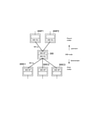
- FIG. 1 is a diagram showing a configuration of a cellular communication system 1 according to an embodiment.
- Cellular communication system 1 is a 5th generation (5G) cellular communication system based on the 3GPP standard. Specifically, the wireless access system in the cellular communication system 1 is NR (New Radio), which is a 5G wireless access system. However, LTE (Long Term Evolution) may be applied to the cellular communication system 1 at least partially.
- 5G 5th generation
- NR New Radio
- LTE Long Term Evolution
- the cellular communication system 1 has a 5G core network (5GC) 10, a user device (UE: User Equipment) 100, a base station (called gNB) 200, and an IAB node 300.
- the IAB node 300 is an example of a relay node.
- the base station is an NR base station
- the base station may be an LTE base station (that is, eNB).
- the 5GC10 has an AMF (Access and Mobility Management Function) 11 and an UPF (User Plane Function) 12.
- the AMF 11 is a device that performs various mobility controls and the like for the UE 100.
- the AMF 11 manages information on the area in which the UE 100 is located by communicating with the UE 100 using NAS (Non-Access Stratum) signaling.
- the UPF 12 is a device that controls the transfer of user data and the like.
- Each gNB 200 is a fixed wireless communication node and manages one or a plurality of cells.
- Cell is used as a term to indicate the smallest unit of wireless communication area.
- Cell may be used as a term to indicate a function or resource for wireless communication with the UE 100.
- One cell belongs to one carrier frequency.
- Each gNB200 is interconnected with the 5GC10 via an interface called an NG interface.
- FIG. 1 illustrates two gNB200-1 and gNB200-2 connected to 5GC10.
- Each gNB200 is interconnected with other gNB200s in an adjacent relationship via an inter-base station interface called an Xn interface.
- FIG. 1 shows an example in which gNB200-1 is connected to gNB200-2.
- Each gNB 200 may be divided into an aggregate unit (CU: Central Unit) and a distributed unit (DU: Distributed Unit).
- the CU and DU are connected to each other via an interface called an F1 interface.
- the F1 protocol is a communication protocol between the CU and the DU, and includes the F1-C protocol, which is a control plane protocol, and the F1-U protocol, which is a user plane protocol.
- the cellular communication system 1 supports IAB that enables wireless relay of NR access by using NR in the backhaul.
- the donor gNB200-1 is a terminal node of the NR backhaul on the network side and is a donor base station having an additional function to support IAB.
- the backhaul can be multi-hop through multiple hops (ie, multiple IAB nodes 300).
- FIG. 1 an example in which the IAB node 300-1 wirelessly connects to the donor gNB200-1, the IAB node 300-2 wirelessly connects to the IAB node 300-1, and the F1 protocol is transmitted in two backhaul hops. Is shown.
- the UE 100 is a mobile wireless communication device that performs wireless communication with a cell.
- the UE 100 may be any device as long as it is a device that performs wireless communication with the gNB 200 or the IAB node 300.
- the UE 100 is a mobile phone terminal, a tablet terminal, a notebook PC, a sensor, a device provided in the sensor, a vehicle, or a device provided in the vehicle.
- the UE 100 wirelessly connects to the IAB node 300 or gNB 200 via an access link.
- FIG. 1 shows an example in which the UE 100 is wirelessly connected to the IAB node 300-2.
- the UE 100 indirectly communicates with the donor gNB200-1 via the IAB node 300-2 and the IAB node 300-1.
- FIG. 2 is a diagram showing the relationship between the IAB node 300, the parent node (Parent nodes), and the child node (Child nodes).
- each IAB node 300 has an IAB-DU corresponding to a base station functional unit and an IAB-MT (Mobile Termination) corresponding to a user equipment functional unit.
- IAB-DU corresponding to a base station functional unit
- IAB-MT Mobile Termination
- the adjacent node (that is, the upper node) on the NR Uu radio interface of the IAB-MT is called the parent node.
- the parent node is the parent IAB node or the DU of the donor gNB200.
- the radio link between the IAB-MT and the parent node is called a backhaul link (BH link).
- FIG. 2 shows an example in which the parent nodes of the IAB node 300 are the IAB nodes 300P1 and 300P2. The direction toward the parent node is called upstream. Seen from the UE 100, the upper node of the UE 100 may correspond to the parent node.
- the adjacent node (that is, the lower node) on the NR access interface of the IAB-DU is called a child node.
- the IAB-DU manages the cell in the same manner as the gNB200.
- the IAB-DU terminates the NR Uu radio interface to the UE 100 and lower IAB nodes.
- the IAB-DU supports the F1 protocol to the CU of donor gNB200-1.
- FIG. 2 shows an example in which the child nodes of the IAB node 300 are the IAB nodes 300C1 to 300C3, the UE 100 may be included in the child nodes of the IAB node 300.
- the direction toward the child node is called downstream.
- FIG. 3 is a diagram showing the configuration of gNB 200.
- the gNB 200 has a wireless communication unit 210, a network communication unit 220, and a control unit 230.
- the wireless communication unit 210 performs wireless communication with the UE 100 and wireless communication with the IAB node 300.
- the wireless communication unit 210 has a reception unit 211 and a transmission unit 212.
- the receiving unit 211 performs various receptions under the control of the control unit 230.
- the receiving unit 211 includes an antenna, converts the radio signal received by the antenna into a baseband signal (received signal), and outputs the radio signal to the control unit 230.
- the transmission unit 212 performs various transmissions under the control of the control unit 230.
- the transmission unit 212 includes an antenna, converts a baseband signal (transmission signal) output by the control unit 230 into a radio signal, and transmits the baseband signal (transmission signal) from the antenna.
- the network communication unit 220 performs wired communication (or wireless communication) with 5GC10 and wired communication (or wireless communication) with other adjacent gNB200.
- the network communication unit 220 has a reception unit 221 and a transmission unit 222.
- the receiving unit 221 performs various types of reception under the control of the control unit 230.
- the receiving unit 221 receives a signal from the outside and outputs the received signal to the control unit 230.
- the transmission unit 222 performs various transmissions under the control of the control unit 230.
- the transmission unit 222 transmits the transmission signal output by the control unit 230 to the outside.
- the control unit 230 performs various controls on the gNB 200.
- the control unit 230 includes at least one memory and at least one processor electrically connected to the memory.
- the memory stores a program executed by the processor and information used for processing by the processor.
- the processor may include a baseband processor and a CPU (Central Processing Unit).
- the baseband processor modulates / demodulates and encodes / decodes the baseband signal.
- the CPU executes a program stored in the memory to perform various processes.
- the processor performs processing of each layer described later.
- FIG. 4 is a diagram showing the configuration of the IAB node 300.
- the IAB node 300 has a wireless communication unit 310 and a control unit 320.
- the IAB node 300 may have a plurality of wireless communication units 310.
- the wireless communication unit 310 performs wireless communication (BH link) with the gNB 200 and wireless communication (access link) with the UE 100.
- the wireless communication unit 310 for BH link communication and the wireless communication unit 310 for access link communication may be provided separately.
- the wireless communication unit 310 has a receiving unit 311 and a transmitting unit 312.
- the receiving unit 311 performs various receptions under the control of the control unit 320.
- the receiving unit 311 includes an antenna, converts the radio signal received by the antenna into a baseband signal (received signal), and outputs the radio signal to the control unit 320.
- the transmission unit 312 performs various transmissions under the control of the control unit 320.
- the transmission unit 312 includes an antenna, converts a baseband signal (transmission signal) output by the control unit 320 into a radio signal, and transmits the baseband signal (transmission signal) from the antenna.
- the control unit 320 performs various controls on the IAB node 300.
- the control unit 320 includes at least one memory and at least one processor electrically connected to the memory.
- the memory stores a program executed by the processor and information used for processing by the processor.
- the processor may include a baseband processor and a CPU.
- the baseband processor modulates / demodulates and encodes / decodes the baseband signal.
- the CPU executes a program stored in the memory to perform various processes.
- the processor performs processing of each layer described later.
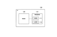
- FIG. 5 is a diagram showing the configuration of the UE 100. As shown in FIG. 5, the UE 100 has a wireless communication unit 110 and a control unit 120.
- the wireless communication unit 110 performs wireless communication on the access link, that is, wireless communication with the gNB 200 and wireless communication with the IAB node 300. Further, the wireless communication unit 110 may perform wireless communication on the side link, that is, wireless communication with another UE 100.
- the wireless communication unit 110 has a reception unit 111 and a transmission unit 112.
- the receiving unit 111 performs various types of reception under the control of the control unit 120.
- the receiving unit 111 includes an antenna, converts the radio signal received by the antenna into a baseband signal (received signal), and outputs the radio signal to the control unit 120.
- the transmission unit 112 performs various transmissions under the control of the control unit 120.
- the transmission unit 112 includes an antenna, converts a baseband signal (transmission signal) output by the control unit 120 into a radio signal, and transmits the baseband signal (transmission signal) from the antenna.
- the control unit 120 performs various controls on the UE 100.
- the control unit 120 includes at least one memory and at least one processor electrically connected to the memory.
- the memory stores a program executed by the processor and information used for processing by the processor.
- the processor may include a baseband processor and a CPU.
- the baseband processor modulates / demodulates and encodes / decodes the baseband signal.
- the CPU executes a program stored in the memory to perform various processes.
- the processor performs processing of each layer described later.
- FIG. 6 is a diagram showing a protocol stack for RRC connection and NAS connection of IAB-MT.
- the IAB-MT of the IAB node 300-2 includes a physical (PHY) layer, a MAC (Medium Access Control) layer, an RLC (Radio Link Control) layer, and a PDCP (Packet Data Control Protocol). It has a layer, an RRC (Radio PHY Control) layer, and a NAS (Non-Access Stratum) layer.
- PHY physical
- MAC Medium Access Control
- RLC Radio Link Control
- PDCP Packet Data Control Protocol
- It has a layer, an RRC (Radio PHY Control) layer, and a NAS (Non-Access Stratum) layer.
- the PHY layer performs coding / decoding, modulation / demodulation, antenna mapping / demapping, and resource mapping / demapping.
- Data and control information are transmitted between the PHY layer of the IAB-MT of the IAB node 300-2 and the PHY layer of the IAB-DU of the IAB node 300-1 via a physical channel.
- the MAC layer performs data priority control, retransmission processing by hybrid ARP (Automatic Repeat Request) (HARQ), random access procedure, and the like. Data and control information are transmitted between the MAC layer of the IAB-MT of the IAB node 300-2 and the MAC layer of the IAB-DU of the IAB node 300-1 via the transport channel.
- the MAC layer of the IAB-DU includes a scheduler. The scheduler determines the transport format (transport block size, modulation / coding method (MCS)) of the upper and lower links and the allocated resource block.
- the RLC layer transmits data to the receiving RLC layer by using the functions of the MAC layer and the PHY layer. Data and control information are transmitted between the RLC layer of the IAB-MT of the IAB node 300-2 and the RLC layer of the IAB-DU of the IAB node 300-1 via a logical channel.
- the PDCP layer performs header compression / decompression and encryption / decryption. Data and control information are transmitted via the radio bearer between the PDCP layer of the IAB-MT of the IAB node 300-2 and the PDCP layer of the donor gNB200.
- the RRC layer controls logical channels, transport channels, and physical channels according to the establishment, re-establishment, and release of radio bearers.
- RRC signaling for various settings is transmitted between the RRC layer of the IAB-MT of the IAB node 300-2 and the RRC layer of the donor gNB200. If there is an RRC connection with the donor gNB200, the IAB-MT is in the RRC connected state. If there is no RRC connection with the donor gNB200, the IAB-MT is in the RRC idle state.
- the NAS layer located above the RRC layer performs session management, mobility management, etc.
- NAS signaling is transmitted between the NAS layer of the IAB-MT of the IAB node 300-2 and the AMF11.
- FIG. 7 is a diagram showing a protocol stack related to the F1-U protocol.
- FIG. 8 is a diagram showing a protocol stack for the F1-C protocol.
- the donor gNB200 is divided into CU and DU.
- each of the IAB-MT of the IAB node 300-2, the IAB-DU of the IAB node 300-1 and the IAB-MT of the IAB node 300-1 and the DU of the donor gNB200 are above the RLC layer. It has a BAP (Backhaul Adjustment Protocol) layer as a layer.
- the BAP layer is a layer that performs routing processing and bearer mapping / demapping processing.
- the IP (Internet Protocol) layer is transmitted via the BAP layer, so that routing with a plurality of hops becomes possible.
- the PDU (Protocol Data Unit) of the BAP layer is transmitted by the backhaul RLC channel (BH NR RLC channel).
- the backhaul RLC channel BH NR RLC channel.
- QoS quality of service
- the protocol stack of the F1-C protocol replaces the GTP-U (GPRS Tunneling Protocol for User Plane) layer and the UDP (User Datagram Protocol) layer shown in FIG. 7, and is an F1AP (Application Protocol) layer. And SCTP (Stream Control Transmission Protocol) layer.
- GTP-U GPRS Tunneling Protocol for User Plane
- UDP User Datagram Protocol
- SCTP Stream Control Transmission Protocol
- the IAB node 300 (specifically, IAB-MT) switches the connection between the donor gNB 200.
- the IAB node 300 may be a movable IAB node 300.
- Connection switching means handover or RRC re-establishment.
- Handover means an operation in which the IAB-MT in the RRC connected state switches cells.
- the RRC re-establishment is an operation in which the IAB-MT in the RRC connected state reconnects with another cell in response to the detection of a wireless link failure.
- the connection switching is a handover will be described, but the connection switching may be an RRC reestablishment.
- the operation of the UE 100 under the IAB node 300 becomes a problem. Specifically, when the IAB node 300 switches the connection between the donor gNB 200, a new operation may be required for the UE 100 under the IAB node 300. However, from the viewpoint of backward compatibility, it is not preferable to make changes to the operation of the UE 100.
- the first embodiment is an embodiment in which the connection switching (for example, handover) of the IAB node 300 between the donor gNB 200 is realized only by changing the operation on the network side (IAB node side) transparently to the UE 100 side.
- a handover may be referred to as an inter-CU handover.
- the IAB node 300 having the UE 100 under its control is a second donor base station different from the first donor base station from the source donor gNB200S which is the first donor base station.
- Handover to a target donor gNB200T is performed.
- the RRC connection between the UE 100 and the source donor gNB200S is continued via the target donor gNB200T.
- the source donor gNB200S uses the RRC connection to transmit a handover command instructing the handover to the target donor gNB200T to the UE 100 via the target donor gNB200T.
- the RRC connection (and PDCP connection) between the UE 100 and the source donor gNB200 continues to be established via the target donor gNB200, and the source donor gNB200S transmits a handover command to the UE 100 using the connection.
- the handover of the IAB node 300 between the donor gNB 200 can be realized without changing the operation of the UE 100.
- a data path may be established between the source donor gNB200S and the target donor gNB200T. From the handover of the IAB node 300 to the completion of the handover of the UE 100, the data transfer processing (that is, data forwarding) of the UE 100 may be performed via this data path. As a result, even if the handover of the IAB node 300 is executed first and then the handover of the UE 100 is performed, the data loss of the UE 100 can be prevented.
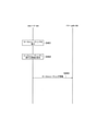
- FIG. 9 is a diagram showing an operation according to the first embodiment.
- step S101 the UE 100 is in a state in which an RRC connection with the source donor gNB200S is established (RRC connected state).
- the IAB node 300 (IAB-MT) is in a state of establishing an RRC connection with the source donor gNB200S (RRC connected state). At least one intermediate IAB node may intervene between the IAB node 300 and the source donor gNB200S.
- the UE 100 is under the control of the IAB node 300 (IAB-DU). That is, the UE 100 uses the cell of the IAB node 300 (IAB-DU) as its own serving cell.
- step S103 the IAB node 300 (IAB-MT) performs RRC reestablishment or handover from the source donor gNB200S to the target donor gNB200T.
- the description will proceed on the assumption that the IAB node 300 (IAB-MT) performs handover.
- step S104 the IAB node 300 (IAB-MT) establishes an RRC connection with the target donor gNB200T as a result of the handover.
- the RRC layer and PDCP layer of the UE 100 remain connected to the source donor gNB200. Therefore, the UE 100 cannot communicate with the target donor gNB200T in either the C plane or the U plane.
- a tunnel (that is, a data forwarding path) is formed between the source donor gNB200S and the target donor gNB200T.
- This tunnel may be configured on the inter-base station interface or over the core network.
- step S105 the UE 100 transmits the uplink user data (User data) to the IAB node 300.
- the IAB node 300 receives the user data.
- step S106 the IAB node 300 transmits the user data from the UE 100 to the target donor gNB200T.
- the target donor gNB200T receives user data.
- step S107 the target donor gNB200T transfers the user data received in step S106 to the source donor gNB200S (Data forwarding).
- the source donor gNB200S receives user data.
- step S108 the source donor gNB200S transfers the user data received in step S107 to UPF12 of the core network.
- step S109 the source donor gNB200S receives the downlink user data (User data) from the UPF12 of the core network.
- step S110 the source donor gNB200S transfers the user data received in step S109 to the target donor gNB200T (Data forwarding).
- the target donor gNB200T receives user data.
- step S111 the target donor gNB200T transfers the user data received in step S110 to the IAB node 300.
- the IAB node 300 receives the user data.
- step S112 the IAB node 300 transmits (relays) the user data received in step S111 to the UE 100.
- the transmission / reception of user data between the UE 100 and the source donor gNB200S continues via the tunnel between the source donor gNB200S and the target donor gNB200T and the target donor gNB200T.
- step S113 the source donor gNB200S transmits a handover command (HO Command) instructing the UE 100 to perform a handover to the target donor gNB200T via the tunnel between the source donor gNB200S and the target donor gNB200T to the target donor gNB200T.
- the target donor gNB200 receives the handover command.
- step S114 the target donor gNB200T transmits an RRC message (RRC Reconnection) including the handover command received in step S113 to the UE 100.
- RRC Reconnection RRC Reconnection
- the target donor gNB200T transmits the RRC message to the UE 100 via the IAB node 300.
- the UE 100 receives the RRC message.
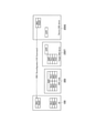
- FIG. 10 is a diagram showing a protocol stack at the time of handover command transmission.
- a handover command (RRC Configuration) is transmitted from the RRC layer of the source donor gNB200S to the RRC layer of the UE 100 via the target donor gNB200T and the IAB node 300.
- Communication between the source donor gNB200S and the target donor gNB200T is performed by inter-base station communication.
- FIG. 9 shows an example of GTP, but the present invention is not limited to this.
- it may be Xn-AP, in which case the handover command is contained (encapsulated) and transmitted in the RRC container of the Xn-AP message.
- the UE 100 transmits an RRC message (RRC Reconnection Complete) indicating the completion of the handover to the target donor gNB200T in response to the handover command. Specifically, the UE 100 transmits the RRC message to the target donor gNB200T via the IAB node 300. The target donor gNB200T receives the RRC message.
- the RACH-less handover may be performed without transmitting the random access preamble and receiving the random access response. In this case, the RACH-less handover may be instructed to the UE 100 in the handover command.
- step S116 the UE 100 establishes an RRC connection with the target donor gNB200T as a result of the handover. From this point, the user data of the UE 100 is switched to communication with the target donor gNB200T.
- step S117 the UE 100 transmits the uplink user data (User data) to the IAB node 300.
- the IAB node 300 receives the user data.
- step S118 the IAB node 300 transmits the user data received in step S117 to the target donor gNB200T.
- the target donor gNB200T receives user data.
- step S119 the target donor gNB200T transfers the user data received in step S118 to UPF12 of the core network.
- step S120 the target donor gNB200T receives the downlink user data (User data) from the UPF12 of the core network.
- User data downlink user data
- step S121 the target donor gNB200T transfers the user data received in step S120 to the IAB node 300.
- the IAB node 300 receives the user data.
- step S122 the IAB node 300 transmits (relays) the user data received in step S121 to the UE 100.
- the second embodiment is an embodiment relating to load balancing within the IAB topology.
- the path in the IAB topology is basically determined semi-fixedly by the routing table (BAP routing ID and path ID), and the CU of the donor gNB 200 collectively manages the routing table.
- BAP routing ID and path ID the routing table
- the CU of the donor gNB 200 collectively manages the routing table.
- the IAB node 300 performs efficient data relay in consideration of the data relay capacity of each of the plurality of relay destination nodes (plurality of paths). Specifically, in the second embodiment, the IAB node 300 that relays data from the relay source node to the plurality of relay destination nodes has the capacity information regarding the data relay capacity of the target IAB node 300 included in the plurality of relay destination nodes. To receive. Then, the IAB node 300 controls data relay based on the received capacity information.
- the capacity information may include information indicating whether or not there are a plurality of nodes of the next hop of the target IAB node 300 included in the plurality of relay destination nodes.
- the target IAB node 300 can be regarded as having a large data relay capacity. Therefore, by preferentially relaying data to such a target IAB node 300, a plurality of paths can be efficiently used.
- the IAB node 300 may receive capacity information for each of the plurality of relay destination nodes, and may control the data transmission ratio to the plurality of relay destination nodes based on the received capacity information. For example, the IAB node 300 relays a large amount of data to a relay destination node having a large data relay capacity, and relays a small amount of data to another relay destination node having a small data relay capacity.
- the IAB node 300 selects a data relay destination from a plurality of relay destination nodes according to the routing setting (routing table) set from the donor gNB 200.
- the IAB node 300 may execute local routing that selects a data relay destination without following the routing setting.
- the predetermined condition may include a condition that a failure occurrence notification or a local routing request is received from any of the plurality of relay destination nodes.
- the IAB node 300 basically performs routing according to the setting from the donor gNB200S, and when a failure occurs or a request occurs in the relay destination node, the IAB node 300 itself performs local routing, which is appropriate depending on the situation. Data can be relayed to various relay destination nodes.
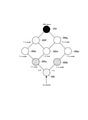
- FIG. 11 is a diagram for explaining the upstream relay operation according to the second embodiment.
- the relay source node of the IAB node 300 is a child node of the IAB node 300
- the relay destination node of the IAB node 300 is the parent node of the IAB node 300.
- an IAB topology including an IAB node 300, other IAB nodes 300a to 300g, and a donor gNB200 is formed.
- the IAB node 300 receives an uplink packet (UL packet) from a child node (which may be a UE 100).
- the IAB node 300 receives the received uplink packet from the parent node IAB node 300a and the parent node based on the routing setting set from the donor gNB 200 and the information (BAP routing ID) included in the header of the uplink packet. / Or relay to the IAB node 300b.
- Each of the IAB nodes 300a to 300g transmits information indicating whether or not there are a plurality of nodes of the next hop of the own node to the child node as the capacity information of the own node.
- capacity information is called "BH connection information”. Specific examples of BH connection information will be described later.
- a BH having one node in the next hop of the own node is called a "single BH", and a BH having two nodes in the next hop of the own node is called a "dual BH".
- each of the IAB nodes 300b, 300c, 300e, 300f, and 300g is a single BH.
- each of the IAB nodes 300a and 300d is a dual BH, and it can be considered that the data relay capacity is larger than that of the single BH.
- the dual BH may be in a state where a dual connection is established by dual connectivity.
- the IAB node 300 determines the transmission ratio based on the BH connection information of the parent node (IAB node 300a, 300b). Since the IAB node 300a is a dual BH and the IAB node 300b is a single BH, the total number of BH links of the parent node is 3. Therefore, when performing local routing, the IAB node 300 sets the transmission ratio to the IAB node 300a to "2/3" and the transmission ratio to the IAB node 300b to the remaining "1/3".
- the transmission ratio of a certain parent node may be set to zero. In this case, the determination of the transmission ratio can be regarded as path selection (path switching).
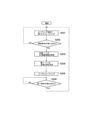
- FIG. 12 is a diagram showing an upstream relay operation according to the second embodiment. This operation may be performed by the IAB node 300, at least a portion of which may be performed by the BAP layer and / or the IAB-MT.
- step S201 the IAB node 300 performs routing based on the routing setting set from the donor gNB 200.
- the IAB node 300 determines whether or not the start condition of the local routing is satisfied.
- the start condition is one of the following. Parameters (threshold values, etc.) that determine the start conditions may be set from the donor gNB 200 to the IAB node 300.
- the BH failure occurrence notification in the parent node is transmitted from the parent node to the IAB node 300 by the BH RLF Inspection, which is a message of the BAP layer.
- the BH failure occurrence notification may be a notification indicating that an RLF (Radio Link Sphere) has occurred in the BH of the parent node, or a notification indicating that the parent node is in the process of recovering from the RLF of the BH. It may be present, or it may be a notification indicating that the recovery of the BH of the parent node from the RLF has failed.
- this condition may be satisfied when the scheduling request (SR) transmitted by the IAB node 300 to a certain parent node is ignored more than a certain number of times (for example, the uplink grant does not come). Comparing the uplink throughputs of the parent nodes, this condition corresponds to the case where there is a certain difference (bias) or more in the uplink throughput for a certain period in the past (and the state continues for a certain period or more). May be good. This condition may be met when the uplink throughput of a certain parent node becomes a certain value or less (and the state continues for a certain period or more).
- the local routing request may be sent from the parent node by a BAP layer message.
- the local routing request may be transmitted from the donor gNB200 via the parent node by an F1 message or an RRC message.
- the IAB node 300 may send a response to a local routing request from the parent node, or may notify the parent node of the transmission ratio described later.
- the local routing request may include an identifier of a bearer (or RLC channel or logical channel) for which local routing is to be performed.
- the IAB node 300 performs local routing for the target bearer (or RLC channel or logical channel) and does not perform local routing for the non-target bearer (or RLC channel or logical channel) (that is, according to the routing table). Do the routing).
- the IAB node 300 can grasp the amount of uplink buffer of the child node based on the buffer status report (BSR) received from the child node.
- BSR buffer status report
- the BSR may be the one in which the uplink buffer amount of the child node (that is, the grandchild node) of the child node is added. This condition may be applicable when the amount of the uplink buffer indicated by the BSR exceeds a certain level (and the state continues for a certain period or longer).
- step S202 When the start condition of the local routing is not satisfied (step S202: No), the IAB node 300 continues the routing based on the routing setting set by the donor gNB200 (step S201).
- the IAB node 300 starts the operation related to the local routing. It should be noted that the IAB node 300 may be able to execute the local routing only when the donor gNB 200 permits the execution of the local routing. This permission is given by the BAP layer message (BAP Control PDU), system information (SIB1), RRC Reconnection, and the like. Whether or not local routing can be executed may be set for each bearer (RLC channel) or may be set collectively for all bearers. Along with such a setting, which of the above conditions is applied and a threshold value used for determining the condition may be set.
- BAP Control PDU BAP Control PDU
- SIB1 system information
- RRC Reconnection Radio Resource Control Protocol
- Whether or not local routing can be executed may be set for each bearer (RLC channel) or may be set collectively for all bearers. Along with such a setting, which of the above conditions is applied and a threshold value used for determining the condition may be set.
- step S203 the IAB node 300 receives the BH connection information of each parent node. Note that step S203 may be performed before step S202.
- the BH connection information of the parent node may include information indicating whether the parent node is a single BH or a dual BH (or a triple BH).
- the BH connection information of the parent node may include a numerical value indicating the number of BHs of the parent node.
- the BH connection information may further include information regarding the capacity of each BH link.
- the information about the capacity of each BH link may be, for example, information indicating at least one of the bandwidth, the number of component carriers, and the frequency band of each BH link, and the average throughput (or the average throughput) of each BH link.
- Information indicating the maximum throughput, GBR (Guaranteed Bit Rate), etc.) may be used.
- the BH connection information may be transmitted from the parent node to the IAB node 300.
- the BH connection information may be an information element included in the BAP Control PDU or system information (for example, SIB1) transmitted by the parent node.
- SIB1 system information
- the parent node may transmit BH connection information when it is dual BH (or triple BH), and may not transmit BH connection information when it is single BH.
- the IAB node 300 determines single BH and dual BH depending on whether or not BH connection information is transmitted.
- the BH connection information may be transmitted from the donor gNB 200 to the IAB node 300. It may be an information element included in an RRC message (for example, RRC Configuration) or an F1 message (for example, DL Information Transfer) transmitted by the donor gNB200.
- RRC message for example, RRC Configuration
- F1 message for example, DL Information Transfer
- the IAB node 300 determines the uplink packet transmission ratio based on the BH connection information received in step S203. As in the above example, when one parent node is dual BH and the other parent node is single BH, the IAB node 300 sets the transmission ratio to the one parent node to "2/3". Then, the transmission ratio to the other parent node is set to "1/3". Here, for example, when the transmission ratio is set to 0: 1, it is considered that the transmission destination has been switched (locally switched). The IAB node 300 may adjust or determine the transmission ratio based on the information contained in the BH connection information (for example, information regarding the capacity of each BH link). The IAB node 300 may adjust or determine the transmission ratio based on the past transmission throughput history for each parent node (or uplink grant history to child nodes (ie, reception throughput)).
- the IAB node 300 performs local routing of the uplink packet based on the transmission ratio determined (and adjusted) in step S204.
- the IAB node 300 may change the header of the locally routed uplink packet. For example, in the BAP header, the routing ID may be changed, or an identifier indicating that the local routing has been performed may be added.
- the IAB node 300 determines whether or not the termination condition of the local routing is satisfied.
- the end condition can be the reverse of the start condition described above. For example, the condition that the BH recovery success notification is received from the parent node, the condition that the throughput to a certain parent is recovered, the condition that the local routing stop request is received, and the buffer state of the child node (and grandchild node) are improved. At least one of the conditions that has been done.
- the termination condition may include the condition that the local routing permission has been revoked (set to disallowed) from the donor gNB200.
- step S206: No If the end condition of the local routing is not satisfied (step S206: No), the IAB node 300 continues the local routing (step S205). On the other hand, when the termination condition of the local routing is satisfied (step S206: Yes), the IAB node 300 performs routing based on the routing setting set by the donor gNB 200 (step S201).
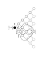
- FIG. 13 is a diagram for explaining the downstream relay operation according to the second embodiment.
- the relay source node of the IAB node 300 is the parent node of the IAB node 300
- the relay destination node of the IAB node 300 is the child node of the IAB node 300.
- the parent node and the child node in the above-mentioned upstream relay operation may be exchanged.
- FIG. 13 shows an example in which each IAB node 300 is a dual BH and there are four paths between the IAB node 300 and the destination node (Destination).
- FIG. 14 is a diagram showing a downstream relay operation according to the second embodiment. This operation may be performed by the IAB node 300, at least a portion of which may be performed by the BAP layer and / or the IAB-DU. Here, the differences from the upstream relay operation will be mainly described.
- step S301 the IAB node 300 performs routing based on the routing setting set from the donor gNB 200.
- the IAB node 300 determines whether or not the start condition of the local routing is satisfied.
- the start condition is one of the following. Parameters (threshold values, etc.) that determine the start conditions may be set from the donor gNB 200 to the IAB node 300.
- the IAB node 300 may be able to execute local routing only when local routing is permitted (configured) by the donor gNB 200.
- the permission may be given by F1 message (F1AP), RRC message, or BAP message.
- the permission may be set for each bearer (RLC channel) or may be set for all bearers at once.
- the permission may be an instruction. Further, which of the following conditions is applied, and a threshold value used for determining the condition may be set.
- the IAB node 300 may determine the radio state from the measurement report from the child node and / or the scheduling result (MCS or the like) for the child node.
- the IAB-DU of the IAB node 300 transmits a Flow control polling BAP Control PDU to the child node and receives a Flow control polledback BAP Control PDU from the child node. Then, the IAB node 300 (IAB-DU) specifies the available buffer size (free buffer amount) indicated by the Flow control feedback feedback BAP Control PDU, and makes a determination.
- step S302 When the start condition of the local routing is not satisfied (step S302: No), the IAB node 300 continues the routing based on the routing setting set by the donor gNB200 (step S301).
- the IAB node 300 starts the operation related to the local routing.
- the IAB node 300 may select a different path having the same destination from the routing settings and send a downlink packet to the IAB node corresponding to the path. Further, the IAB node 300 may change the header of the downlink packet that has been locally routed. For example, in the BAP header, the routing ID may be changed, or an identifier indicating that the local routing has been performed may be added.
- the IAB node 300 may receive the available buffer size information from each child node.
- the IAB node 300 determines the selection of the downstream path and / or the transmission ratio to the child node. Specifically, the IAB node 300 selects another path having the same destination from the stored routing settings. The IAB node 300 may select a plurality of paths, and in this case, the transmission ratio may be determined in the same manner as in the upstream relay operation described above. Selectable path combinations may be preset for the donor gNB 200 to the IAB node 300.
- step S305 the IAB node 300 performs local routing according to the result of step S304.
- the IAB node 300 determines whether or not the termination condition of the local routing is satisfied.
- the end condition can be the reverse of the start condition described above. For example, at least one of the conditions that the throughput of a certain path is recovered above a certain level, the radio state of the child node is recovered above a certain level, and the available buffer size of the child node is recovered above a certain level.
- the termination condition may include the condition that the local routing permission has been revoked (set to disallowed) from the donor gNB200.
- step S306 If the end condition of the local routing is not satisfied (step S306: No), the IAB node 300 continues the local routing (step S305). On the other hand, when the termination condition of the local routing is satisfied (step S306: Yes), the IAB node 300 performs routing based on the routing setting set by the donor gNB 200 (step S301).
- the donor gNB 200 may not be able to grasp the content of the local routing executed by the IAB node 300 (when it was executed and how many times it was executed). If local routing is performed, there may be a flaw in the routing settings by the donor gNB200, or a failure in the IAB topology. Therefore, it is preferable that the donor gNB200 can grasp the contents of the local routing. This allows, for example, the donor gNB200 to optimize the routing settings.
- the IAB node 300 that relays data from the relay source node to a plurality of relay destination nodes selects a data relay destination from the plurality of relay destination nodes according to the routing setting set from the donor gNB 200.
- the IAB node 300 executes local routing that selects a data relay destination without following the routing setting (see the second embodiment).
- the IAB node 300 transmits historical information regarding this local routing (that is, information indicating the contents of the local routing) to the donor gNB 200.
- FIG. 15 is a diagram showing the operation of the modified example 1 of the second embodiment.
- step S401 the IAB node 300 performs local routing.
- the IAB node 300 stores information (local routing information) related to the local routing executed in step S401.
- the IAB node 300 stores the local routing information each time the local routing is performed.
- the local routing information may include at least one of a time stamp indicating the execution time of the local routing, a position information (latitude / longitude altitude) indicating the execution time of the local routing, and information indicating the radio status at the time of executing the local routing. good.
- the local routing information may include a routing ID (path ID and Destiny) before and after the change by local routing.
- the local routing information may include the topology ID (may be donor gNB ID, gNB-CU ID) of the IAB topology being connected.
- the local routing information may include information indicating the reason (or condition) for executing the local routing.
- the local routing information may include information indicating the period during which the local routing was performed (start time, end time) and / or the number of times the local routing was performed.
- the local routing information may be stored in the BAP layer, or may be reported from the BAP layer to the RRC layer each time and stored in the RRC layer.
- the IAB node 300 transmits the local routing information saved in step S402 to the donor gNB200.
- Local routing information is transmitted from the IAB node 300, for example, by an RRC message.
- the local routing information may be transmitted as a response message in response to a request from the donor gNB200.
- the local routing information may be transmitted as a UE Information Response to the UE Information Request.
- This modification is an embodiment in which the donor gNB 200 changes the routing setting of the IAB node 300 at the request of the IAB node 300.
- the IAB node 300 that relays data from the relay source node to a plurality of relay destination nodes selects a data relay destination from the plurality of relay destination nodes according to the routing setting set from the donor gNB 200.
- the IAB node 300 sends a routing change request to the donor gNB 200 to change the routing setting.
- FIG. 16 is a diagram showing the operation of the modified example 2 of the second embodiment.
- the IAB node 300 transmits a routing change request to the donor gNB 200.
- the routing change request may be a notification that the routing change is desired.
- the routing change request may be an RRC message or an F1 (F1AP) message.
- the routing change request may be specified separately for the upstream routing change and the downstream routing change.
- the routing change request may be transmitted only when transmission is permitted by the donor gNB200.
- the IAB node 300 may send a routing change request with the same condition as the start condition of the local routing described in the second embodiment described above being satisfied as a trigger.
- the conditions and determination thresholds to be used may be set from the donor gNB 200 to the IAB node 300.
- the IAB node 300 may transmit the routing change request only when the transmission of the routing change request is permitted (set) by the donor gNB 200.
- the routing change request includes information indicating the reason (or condition) that the routing setting change is necessary, the routing ID (path ID, Destination) of the setting change target, and the RLC Channel ID (bearer ID, LCID may be used) of the setting change target. Of these, at least one may be included.
- the IAB node 300 may include its own BSR value in the routing change request. Further, the IAB node 300 may include the BSR value in the routing change request for each parent node (in the case of dual connectivity) in the dual BH (in the case of dual connectivity, the IAB node 300 may include the BSR value of its own child node or it. The added own BSR value may be included in the routing change request. Such transmission of the BSR value may be periodically performed by each IAB node 300 in the IAB topology to the donor gNB 200.
- the IAB node 300 may include its own available buffer size value and / or its own child node's available buffer size value (Flow control fedback BAP Control PDU value) in the routing change request. ..
- Each IAB node 300 in the IAB topology may periodically transmit such available buffer size values to the donor gNB 200.
- the donor gNB 200 changes the routing setting of the IAB node 300 in response to the routing change request received in step S501.
- the IAB node 300 may perform a handover of the IAB node 300 (that is, change the IAB topology) as necessary.
- the IAB node 300 may start a timer when the routing change request is transmitted, and the transmission of the next routing change request may be prohibited until the timer expires.
- the timer value of this timer may be set from the donor gNB 200 to the IAB node 300.
- the relay transmission by IAB has been described as an example, but the present invention is not limited to this, and may be applied to other relay transmission systems.
- the operation according to the above-described embodiment and modification may be applied to a relay node (layer 3 relay node), a side link relay (relay node using a side link used for direct communication between user devices), and the like. ..
- the base station in the cellular communication system 1 may be an eNB which is an LTE base station.
- the core network in the cellular communication system 1 may be an EPC (Evolved Packet Core).
- the gNB may be connected to the EPC
- the eNB may be connected to the 5GC
- the gNB and the eNB may be connected via an inter-base station interface (Xn interface, X2 interface).
- a program for causing a computer to execute each process according to the above-described embodiment and modification may be provided.
- the program may also be recorded on a computer-readable medium.
- Computer-readable media can be used to install programs on a computer.
- the computer-readable medium on which the program is recorded may be a non-transient recording medium.
- the non-transient recording medium is not particularly limited, but may be, for example, a recording medium such as a CD-ROM or a DVD-ROM.
- a chipset composed of a memory for storing a program for executing each process performed by the UE 100, gNB 200, or the IAB node 300 and a processor for executing the program stored in the memory may be provided.
- Topology Adaptation Enhancements-Procedure specifications for interdonor IAB node movement to enhance robustness and load balancing, including enhancements to reduce signaling load. -Specifications of extended functions for reducing service interruptions due to IAB node movement and BH RLF recovery. -Extended specifications for topology redundancy, including support for CP / UP isolation. Topology, Routing, and Transport Enhancements-Extension specifications to improve overall topology fairness, multi-hop delay, and congestion mitigation.
- BH backhaul
- BH RLF BH RLF indication
- existing functions such as RRC re-establishment, MCG / SCG failure indication, and / or conditional handover. Only the recovery procedure was specified.
- Proposal 1 RAN2 should assume that the quality of the backhaul link will change dynamically. Therefore, the backhaul RLF is not a rare case like the Rel-17 eIAB.
- Proposal 2 RAN2 should agree that BH RLF indication type 2 "attempting recovery" has been introduced. Further consideration is needed as to whether it is transmitted via BAP Control PDU, SIB1, or both.
- Type 3 "BH link recovery" in Rel-17 as well.
- the type 3 indication is transmitted via the BAP Control PDU, there is an advantage that the downstream IAB node can quickly know the BH link recovery.
- the UE since the UE does not have a BAP layer, the fact cannot be known. Therefore, RAN2 should discuss whether Type 3 indications are needed.
- Proposal 3 If Proposal 3 can be agreed, RAN2 should discuss whether explicit BH RLF indications when BH RLF is gone, ie, type 3 "BH link recovery", will be introduced.
- Proposal 4 RAN2 should agree to reduce / stop scheduling requests after IAB-MT receives a Type 2 indication and resume scheduling requests when the parent node runs out of BH RLF. be.
- Proposal 5 RAN2 should discuss any other IAB-MT behavior while the parent node is trying to recover the BH link.
- the IAB-DU that sends the indication
- the type 2 BH RLF indication will be sent.
- RLF occurs on this BH link
- an indication is transmitted, so it is easy for a single-connection BH.
- the IAB node detects an RLF on the MCG, it initiates the MCG fault information procedure, but the SCG continues to function as a BH link, so it may not be necessary to send a Type 2 indication at this point.
- the IAB-MT initiates RRC re-establishment, at which point a Type 2 indication is transmitted. Therefore, the type 2 indication is transmitted when the RRC reestablishment is initiated, not when the MCG / SCG failure information is triggered. In any case, this is intended for IAB-DU behavior, so careful consideration should be given to whether / how to capture to specifications. That is, in stages 2 and 3, it should be considered whether note needs to be added or nothing needs to be captured.
- Proposal 6 RAN2 agrees that IAB-DU may send a Type 2 BH RLF indication when it initiates RRC reestablishment rather than when it initiates any of the RLF recovery procedures. Should be.
- Proposal 7 RAN2 should discuss whether / how to capture the IAB-DU behavior (ie, Proposal 6) in the specification.
- Finding 4 In Rel-16, when the IAB node attempts an RRC re-establishment request to a descendant node, the IAB node must wait for the failure and finally move to idle.
- Proposal 8 RAN2 should agree that optimization of cell (re) selection is considered to avoid re-establishment to inappropriate nodes (eg, descendant nodes).
- the common concept is considered to be that the IAB-MT is provided in either whitelist or blacklist for the purpose of cell selection.
- Whitelists and blacklists have advantages depending on the topology and the location of the IAB node, given that topology changes can occur frequently on Rel-17, for example due to "moving interdonor IAB nodes". And there are disadvantages.
- the blacklist has the advantage of low overhead in this case, as it contains, for example, only the downstream IAB nodes of the IAB node of concern, and in some cases only a small number of child IAB nodes.
- Findings 5 Whitelists and blacklists have advantages and disadvantages depending on the topology and location of the IAB node.
- the IAB donor or parent IAB node
- Proposal 9 RAN2 should agree that the IAB-MT will be provided with a whitelist or blacklist (ie, a selection structure) for the purpose of cell selection to avoid re-establishment to descendant nodes. Further consideration is needed as to whether these lists can also be used for cell reselection procedures.
- a whitelist or blacklist ie, a selection structure
- Proposal 9 can be agreed, further consideration should be given to the information, that is, how to provide the white list or blacklist.
- Option 1 assumes a CHO setting and may require some extensions.
- Option 2 envisions additional indications, such as type 2 BH RLF indications.
- Option 3 is intended to provide information about the entire topology that is not in the existing configuration.
- Option 5 is supposed to be set by OAM, but as the reporter pointed out, this is suspicious.
- the whitelist / blacklist The delivery method should be a dynamic method. Therefore, option 5, ie OAM, should be excluded. Which method, i.e. which of options 1, 2, or 3 should be the baseline for the extension, needs further consideration.
- Proposal 10 RAN2 should agree that the whitelist / blacklist is dynamically provided by the parent IAB node or IAB donor each time the topology changes. Further studies are needed for details.
- the second solution "rerouting buffered PDCP PDUs on the intermediate IAB node," was supported as an implementation choice at the BAP layer. Further, the BAP layer may be executed "for example, data buffering in the transmission part of the BAP entity is implementation-dependent until the RLC-AM entity receives the acknowledgment". These BAP implementations were considered to avoid packet loss in the "most" cases of the Rel-16 deployment scenario, i.e. when using fixed IAB nodes, but are not perfect, for example, as in Figure 19. rice field.
- the third solution “Introduction of UL Status Delivery,” was a promised solution to guarantee lossless delivery of UL data in view of the evaluation results cited in FIG.
- the idea was to delay the RLC ARQ to the UE so that it would start when PDCP data recovery in the UE was needed.
- a fixed IAB node was assumed, it was considered rare that UL packets were dropped due to a topology change, so it was not specified in Rel-16.
- RAN2 should discuss, in addition to the results captured by TR, an extended mechanism to ensure lossless delivery within the L2 multihop network.
- Proposal 11 is a solution identified in TR38.874, a mechanism that guarantees lossless delivery under conditions where topology changes may occur frequently based on some form of "UL status delivery". Should be agreed to be introduced.
- C-2 should be an extended baseline for Rel-17 for lossless delivery of UL packets.
- C-2 which is the solution to "introduction of UL status distribution" may be an extended baseline for Rel-17, which can also be implemented for Rel-16.
- Rel-17 should assume a dynamic topology change that causes UL packet loss
- the extension of Rel-17 will support C-2 as a standard support function.
- At least the stage 2 specification should explain the overall mechanism based on C-2. Otherwise, the 3GPP standard does not guarantee lossless delivery during the handover of the IAB node.
- small changes such as RLC and / or BAP are expected in Stage 3, but details may not be specified as they are considered internal behavior of the IAB node.
- Proposal 12 RAN2 should agree to specify an RLC ARQ mechanism for lossless delivery of UL packets in stage 2. This delays the transmission of the ACK to the child node / UE before receiving the ACK from the parent IAB node (ie, C-2). Whether or not to specify in stage 3 / how to specify it needs further consideration.
Landscapes
- Engineering & Computer Science (AREA)
- Computer Networks & Wireless Communication (AREA)
- Signal Processing (AREA)
- Mobile Radio Communication Systems (AREA)
Abstract
Description
まず、実施形態に係るセルラ通信システムの構成について説明する。図1は、実施形態に係るセルラ通信システム1の構成を示す図である。
次に、実施形態に係る基地局であるgNB200の構成について説明する。図3は、gNB200の構成を示す図である。図3に示すように、gNB200は、無線通信部210と、ネットワーク通信部220と、制御部230とを有する。
次に、実施形態に係る中継ノードであるIABノード300の構成について説明する。図4は、IABノード300の構成を示す図である。図4に示すように、IABノード300は、無線通信部310と、制御部320とを有する。IABノード300は、無線通信部310を複数有していてもよい。
次に、実施形態に係るユーザ装置であるUE100の構成について説明する。図5は、UE100の構成を示す図である。図5に示すように、UE100は、無線通信部110と、制御部120とを有する。
次に、実施形態に係るプロトコルスタックの構成について説明する。図6は、IAB-MTのRRC接続及びNAS接続に関するプロトコルスタックを示す図である。
次に、上述のようなセルラ通信システム1の構成を前提として、セルラ通信システム1の動作について説明する。
次に、第2実施形態について、上述の実施形態との相違点を主として説明する。
第2実施形態に係るアップストリーム中継動作について説明する。
例えば、親ノードにおけるBHの障害発生通知は、BAPレイヤのメッセージであるBH RLF Indicationにより親ノードからIABノード300に送信される。BHの障害発生通知は、親ノードのBHでRLF(Radio Link Failure)が発生したことを示す通知であってもよいし、親ノードがBHのRLFからのリカバリ処理中であることを示す通知であってもよいし、親ノードのBHのRLFからのリカバリに失敗したことを示す通知であってもよい。
例えば、ある親ノードに対してIABノード300が送信したスケジューリング要求(SR)が一定回数以上無視された(例えば、上りリンクグラントが来なかった)場合が本条件に該当してもよい。親ノード同士の上りリンクスループットを比較して、過去一定期間上りリンクスループットに一定以上の差(偏り)が発生した場合(かつ、その状態が一定期間以上継続した場合)が本条件に該当してもよい。ある親ノードの上りリンクスループットが一定値以下となった場合(かつ、その状態が一定期間以上継続した場合)が本条件に該当してもよい。
ローカルルーティング要求は、BAPレイヤのメッセージにより親ノードから送信されてもよい。ローカルルーティング要求は、F1メッセージ又はRRCメッセージによりドナーgNB200から親ノード経由で送信されてもよい。IABノード300は、親ノードからのローカルルーティング要求に対して応答を送信してもよいし、後述の送信比率を親ノードに通知してもよい。
例えば、IABノード300は、子ノードから受信するバッファ状態報告(BSR)に基づいて子ノードの上りリンクバッファ量を把握できる。BSRは、当該子ノードのさらに子ノード(すなわち、孫ノード)の上りリンクバッファ量を加味したものであってもよい。BSRが示す上りリンクバッファ量が一定以上になった場合(かつ、その状態が一定期間以上継続した場合)が本条件に該当してもよい。
第2実施形態に係るダウンストリーム中継動作について説明する。
例えば、IABノード300は、子ノードからの測定報告及び/又は子ノードに対するスケジューリング結果(MCS等)から無線状態を判定してもよい。
例えば、IABノード300のIAB-DUは、Flow control polling BAP Control PDUを子ノードへ送信し、Flow control feedback BAP Control PDUを子ノードから受信する。そして、IABノード300(IAB-DU)は、Flow control feedback BAP Control PDUで示される利用可能バッファサイズ(空きバッファ量)を特定し、判定を行う。
次に、第2実施形態の変更例1について、上述の実施形態との相違点を主として説明する。
次に、第2実施形態の変更例2について、上述の実施形態との相違点を主として説明する。本変更例は、IABノード300からの要求によりドナーgNB200がIABノード300のルーティング設定を変更する実施例である。
上述の実施形態及び変更例は、別々の実施形態及び変更例を相互に組み合わせて実施可能である。また、第2実施形態の変更例1及び2は、第2実施形態と併用してもよいし、第2実施形態とは別に実施してもよい。
(導入)
NR eIAB(Enhancements to Integrated Access AND Backhaul)に関する改訂されたワークアイテムが承認された。いくつかの目的は次の通りである。
・シグナリング負荷を軽減するための機能拡張を含む、堅牢性及び負荷分散を強化するためのインタードナーIABノード移動のための手順の仕様。
・IABノード移動及びBH RLF回復によるサービス中断削減のための拡張機能の仕様。
・CP/UP分離のサポートを含む、トポロジの冗長性に対する拡張の仕様。
トポロジ、ルーティング、及びトランスポートの機能拡張
・トポロジ全体の公平性、マルチホップ遅延、及び輻輳緩和を改善するための拡張機能の仕様。
(バックホールリンク品質の想定)
Rel-15の研究段階で、TRは、要件の背景の1つとして、「無線バックホールリンクは、車両などの移動物体、季節の変化(葉)、インフラストラクチャの変化(新しい建物)などによる閉塞に対して脆弱である。このような脆弱性は、物理的に静止しているIABノードにも当てはまる。」と述べている。そのため、TRでキャプチャされたように、マルチホップ/無線バックホールに起因するさまざまな課題とこれらの潜在的な解決策が研究された。
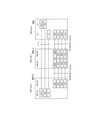
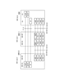
Rel-16のEメールディスカッションでは、図17に示すような4種類のBH RLF通知が議論された。
RRC再確立手順では、IAB-MTは、適切なセルを見つけるために、最初にセル選択手順を実行する。このセル選択手順では、IAB-MTが子孫ノードを選択する可能性があるなど、潜在的な課題がRel-16で指摘された。従って、それはEメールディスカッションで議論された。
Rel-15の研究段階では、マルチホップRLC ARQの課題が、TRのセクション8.2.3で議論され、キャプチャされた。Rel-16では、プロトコルスタックは分離されていないRLC層を有するIABに対して定義された。つまり、Rel-16では、end-to-end ARQは除外され、hop-by-hop ARQが採用された。
Claims (12)
- セルラ通信システムで用いる通信制御方法であって、
中継元ノードから複数の中継先ノードへデータ中継を行う中継ノードが、ドナー基地局から設定されたルーティング設定に従って前記複数の中継先ノードの中からデータ中継先を選択することと、
前記中継ノードが、所定条件が満たされた場合、前記ルーティング設定に従わずに前記データ中継先を選択するローカルルーティングを実行することと、を有し、
前記所定条件は、前記複数の中継先ノードのいずれかから障害発生通知を受信したという条件を含む
通信制御方法。 - 前記所定条件は、前記複数の中継先ノードのいずれかからflow controlに関する情報を受信したという条件を含む
請求項1に記載の通信制御方法。 - 前記所定条件は、前記複数の中継先ノードのいずれかからローカルルーティング要求を受信したという条件を含む
請求項1又は2に記載の通信制御方法。 - 前記所定条件は、前記中継ノード又は前記中継元ノードのいずれかの上りリンクバッファ量が一定以上になったという条件を含む
請求項1乃至3のいずれか1項に記載の通信制御方法。 - 前記中継ノードが、ドナーノードから前記ローカルルーティングを許可することを示す情報を受信することをさらに含む
請求項1乃至4のいずれか1項に記載の通信制御方法。 - セルラ通信システムで用いる通信制御方法であって、
配下にユーザ装置を有する中継ノードが、第1ドナー基地局から第2ドナー基地局への接続切替を行うことと、
前記接続切替を行っても、前記ユーザ装置と前記第1ドナー基地局との間のRRC(Radio Resource Control)接続を前記第2ドナー基地局経由で継続することと、
前記第1ドナー基地局が、前記RRC接続を用いて、前記第2ドナー基地局へのハンドオーバを指示するハンドオーバ指令を前記第2ドナー基地局経由で前記ユーザ装置に送信することと、を有する
通信制御方法。 - 前記第1ドナー基地局と前記第2ドナー基地局との間にデータパスを確立することと、
前記接続切替から前記ハンドオーバの完了までにおいて、前記データパスを介して前記ユーザ装置のデータの転送処理を行うことと、をさらに有する
請求項6に記載の通信制御方法。 - セルラ通信システムで用いる通信制御方法であって、
中継元ノードから複数の中継先ノードへデータ中継を行う中継ノードが、前記複数の中継先ノードに含まれる対象中継ノードのデータ中継容量に関する容量情報を受信することと、
前記中継ノードが、前記容量情報に基づいて前記データ中継を制御することと、を有する
通信制御方法。 - 前記容量情報は、前記対象中継ノードの次ホップのノードが複数存在するか否かを示す情報を含む
請求項8に記載の通信制御方法。 - 前記受信することは、前記中継ノードが、前記複数の中継先ノードのそれぞれの前記容量情報を受信することを含み、
前記制御することは、前記容量情報に基づいて、前記複数の中継先ノードに対するデータ送信比率を制御することを含む
請求項8又は9に記載の通信制御方法。 - セルラ通信システムで用いる通信制御方法であって、
中継元ノードから複数の中継先ノードへデータ中継を行う中継ノードが、ドナー基地局から設定されたルーティング設定に従って、前記複数の中継先ノードの中からデータ中継先を選択することと、
前記中継ノードが、前記ルーティング設定を変更するためのルーティング変更要求を前記ドナー基地局に送信することと、を有する
通信制御方法。 - セルラ通信システムで用いる通信制御方法であって、
中継元ノードから複数の中継先ノードへデータ中継を行う中継ノードが、ドナー基地局から設定されたルーティング設定に従って、前記複数の中継先ノードの中からデータ中継先を選択することと、
前記中継ノードが、所定条件が満たされた場合、前記ルーティング設定に従わずに前記データ中継先を選択するローカルルーティングを実行することと、
前記ローカルルーティングに関する履歴情報を前記ドナー基地局に送信することと、を有する
通信制御方法。
Priority Applications (7)
| Application Number | Priority Date | Filing Date | Title |
|---|---|---|---|
| CN202510461340.2A CN120282237A (zh) | 2020-08-06 | 2021-08-05 | 通信控制方法、中继节点以及处理器 |
| JP2022541725A JP7328458B2 (ja) | 2020-08-06 | 2021-08-05 | 通信制御方法、中継ノード及びプロセッサ |
| EP21853606.8A EP4178246B1 (en) | 2020-08-06 | 2021-08-05 | Iab local routing conditioned by buffer size |
| CN202180068277.6A CN116325849A (zh) | 2020-08-06 | 2021-08-05 | 通信控制方法 |
| US18/164,242 US12574986B2 (en) | 2020-08-06 | 2023-02-03 | Communication control method |
| JP2023127002A JP7594637B2 (ja) | 2020-08-06 | 2023-08-03 | 通信制御方法、第1ドナー基地局、及びシステム |
| JP2024204065A JP7814477B2 (ja) | 2020-08-06 | 2024-11-22 | 通信制御方法、第1ドナー基地局、及びシステム |
Applications Claiming Priority (2)
| Application Number | Priority Date | Filing Date | Title |
|---|---|---|---|
| US202063061887P | 2020-08-06 | 2020-08-06 | |
| US63/061,887 | 2020-08-06 |
Related Child Applications (1)
| Application Number | Title | Priority Date | Filing Date |
|---|---|---|---|
| US18/164,242 Continuation US12574986B2 (en) | 2020-08-06 | 2023-02-03 | Communication control method |
Publications (1)
| Publication Number | Publication Date |
|---|---|
| WO2022030578A1 true WO2022030578A1 (ja) | 2022-02-10 |
Family
ID=80118104
Family Applications (1)
| Application Number | Title | Priority Date | Filing Date |
|---|---|---|---|
| PCT/JP2021/029108 Ceased WO2022030578A1 (ja) | 2020-08-06 | 2021-08-05 | 通信制御方法 |
Country Status (5)
| Country | Link |
|---|---|
| US (1) | US12574986B2 (ja) |
| EP (1) | EP4178246B1 (ja) |
| JP (3) | JP7328458B2 (ja) |
| CN (2) | CN116325849A (ja) |
| WO (1) | WO2022030578A1 (ja) |
Cited By (3)
| Publication number | Priority date | Publication date | Assignee | Title |
|---|---|---|---|---|
| WO2023169153A1 (zh) * | 2022-03-07 | 2023-09-14 | 华为技术有限公司 | 通信方法和装置 |
| US20230413127A1 (en) * | 2020-10-21 | 2023-12-21 | Fujitsu Limited | Migration method and apparatus for iab-node |
| JPWO2024034571A1 (ja) * | 2022-08-08 | 2024-02-15 |
Families Citing this family (5)
| Publication number | Priority date | Publication date | Assignee | Title |
|---|---|---|---|---|
| GB2605492B (en) * | 2021-03-30 | 2026-04-01 | Samsung Electronics Co Ltd | Improvements in and relating to data loss due to donor change in a multi-hop network |
| US12156187B2 (en) * | 2021-11-23 | 2024-11-26 | At&T Intellectual Property I, L.P. | Frequency division multiplexing operation for integrated access and backhaul (IAB) |
| US12556990B2 (en) * | 2022-12-14 | 2026-02-17 | Verizon Patent And Licensing Inc. | Systems and methods for handover for mobile integrated access and backhaul nodes |
| KR20240163896A (ko) * | 2023-05-11 | 2024-11-19 | 삼성전자주식회사 | 차세대 이동통신 시스템에서 액세스 백홀 결합 시스템의 이동을 위한 랜덤 액세스 없이 핸드오버를 하는 방법 및 장치 |
| JP7619407B1 (ja) | 2023-09-08 | 2025-01-22 | artience株式会社 | 活性エネルギー線硬化型組成物 |
Citations (7)
| Publication number | Priority date | Publication date | Assignee | Title |
|---|---|---|---|---|
| JP2000004469A (ja) * | 1998-06-17 | 2000-01-07 | Nec Corp | 無線通信システムと基地装置及び無線伝送路最適化の方法 |
| JP2004096247A (ja) * | 2002-08-29 | 2004-03-25 | Ntt Docomo Inc | データ通信システム、データ通信方法、通信端末及び中継装置 |
| JP2014500662A (ja) * | 2010-11-05 | 2014-01-09 | インターデイジタル パテント ホールディングス インコーポレイテッド | 中継ノードのインタフェースに関連するレイヤ2測定およびネットワーク負荷平衡時の中継ノードの扱い |
| JP2015084601A (ja) * | 2015-02-04 | 2015-04-30 | 京セラ株式会社 | 無線中継局及び制御方法 |
| JP2018533311A (ja) * | 2015-11-05 | 2018-11-08 | ソニー株式会社 | 無線通信システムにおける電子装置及び無線通信方法 |
| US20190223078A1 (en) * | 2018-03-28 | 2019-07-18 | Alexander Sirotkin | Next generation node-b (gnb) for integrated access and backhaul (iab) relay in new radio (nr) networks |
| WO2020064861A1 (en) * | 2018-09-27 | 2020-04-02 | Sony Corporation | Methods, wireless communications networks and infrastructure equipment |
Family Cites Families (8)
| Publication number | Priority date | Publication date | Assignee | Title |
|---|---|---|---|---|
| WO2016155991A1 (en) * | 2015-03-31 | 2016-10-06 | Sony Corporation | Congestion avoidance in a network with base station and relay nodes |
| WO2020032127A1 (ja) * | 2018-08-08 | 2020-02-13 | 京セラ株式会社 | 中継装置 |
| JP7301059B2 (ja) * | 2018-09-14 | 2023-06-30 | 株式会社Nttドコモ | 無線通信装置、無線通信方法及びシステム |
| CN115190531B (zh) * | 2019-04-30 | 2025-10-03 | 华为技术有限公司 | 数据传输的方法和装置 |
| CN114868369A (zh) * | 2019-12-31 | 2022-08-05 | 联想(北京)有限公司 | 用于在通信系统中路由数据的方法及设备 |
| US20230139323A1 (en) * | 2020-03-11 | 2023-05-04 | Sharp Kabushiki Kaisha | Notification message for backhaul radio link failure in wireless relay networks |
| EP4128990A1 (en) * | 2020-04-02 | 2023-02-08 | Telefonaktiebolaget LM Ericsson (publ) | Preventing reestablishment at descendant nodes with no alternative paths in integrated access backhaul |
| EP4233384A1 (en) * | 2020-10-22 | 2023-08-30 | Telefonaktiebolaget LM Ericsson (publ) | Rerouting of ul/dl traffic in an iab network |
-
2021
- 2021-08-05 EP EP21853606.8A patent/EP4178246B1/en active Active
- 2021-08-05 JP JP2022541725A patent/JP7328458B2/ja active Active
- 2021-08-05 CN CN202180068277.6A patent/CN116325849A/zh active Pending
- 2021-08-05 WO PCT/JP2021/029108 patent/WO2022030578A1/ja not_active Ceased
- 2021-08-05 CN CN202510461340.2A patent/CN120282237A/zh active Pending
-
2023
- 2023-02-03 US US18/164,242 patent/US12574986B2/en active Active
- 2023-08-03 JP JP2023127002A patent/JP7594637B2/ja active Active
-
2024
- 2024-11-22 JP JP2024204065A patent/JP7814477B2/ja active Active
Patent Citations (7)
| Publication number | Priority date | Publication date | Assignee | Title |
|---|---|---|---|---|
| JP2000004469A (ja) * | 1998-06-17 | 2000-01-07 | Nec Corp | 無線通信システムと基地装置及び無線伝送路最適化の方法 |
| JP2004096247A (ja) * | 2002-08-29 | 2004-03-25 | Ntt Docomo Inc | データ通信システム、データ通信方法、通信端末及び中継装置 |
| JP2014500662A (ja) * | 2010-11-05 | 2014-01-09 | インターデイジタル パテント ホールディングス インコーポレイテッド | 中継ノードのインタフェースに関連するレイヤ2測定およびネットワーク負荷平衡時の中継ノードの扱い |
| JP2015084601A (ja) * | 2015-02-04 | 2015-04-30 | 京セラ株式会社 | 無線中継局及び制御方法 |
| JP2018533311A (ja) * | 2015-11-05 | 2018-11-08 | ソニー株式会社 | 無線通信システムにおける電子装置及び無線通信方法 |
| US20190223078A1 (en) * | 2018-03-28 | 2019-07-18 | Alexander Sirotkin | Next generation node-b (gnb) for integrated access and backhaul (iab) relay in new radio (nr) networks |
| WO2020064861A1 (en) * | 2018-09-27 | 2020-04-02 | Sony Corporation | Methods, wireless communications networks and infrastructure equipment |
Non-Patent Citations (2)
| Title |
|---|
| See also references of EP4178246A4 |
| SONY: "Routing details in IAB", 3GPP DRAFT; R2-1913295, 3RD GENERATION PARTNERSHIP PROJECT (3GPP), MOBILE COMPETENCE CENTRE ; 650, ROUTE DES LUCIOLES ; F-06921 SOPHIA-ANTIPOLIS CEDEX ; FRANCE, vol. RAN WG2, no. Chongqing, China; 20191014 - 20191018, 3 October 2019 (2019-10-03), Mobile Competence Centre ; 650, route des Lucioles ; F-06921 Sophia-Antipolis Cedex ; France , XP051791304 * |
Cited By (3)
| Publication number | Priority date | Publication date | Assignee | Title |
|---|---|---|---|---|
| US20230413127A1 (en) * | 2020-10-21 | 2023-12-21 | Fujitsu Limited | Migration method and apparatus for iab-node |
| WO2023169153A1 (zh) * | 2022-03-07 | 2023-09-14 | 华为技术有限公司 | 通信方法和装置 |
| JPWO2024034571A1 (ja) * | 2022-08-08 | 2024-02-15 |
Also Published As
| Publication number | Publication date |
|---|---|
| US20230180327A1 (en) | 2023-06-08 |
| US12574986B2 (en) | 2026-03-10 |
| EP4178246A1 (en) | 2023-05-10 |
| JP2025024206A (ja) | 2025-02-19 |
| JP2023145706A (ja) | 2023-10-11 |
| JP7814477B2 (ja) | 2026-02-16 |
| JP7328458B2 (ja) | 2023-08-16 |
| CN120282237A (zh) | 2025-07-08 |
| EP4178246B1 (en) | 2025-09-24 |
| CN116325849A (zh) | 2023-06-23 |
| JP7594637B2 (ja) | 2024-12-04 |
| EP4178246A4 (en) | 2024-01-03 |
| JPWO2022030578A1 (ja) | 2022-02-10 |
Similar Documents
| Publication | Publication Date | Title |
|---|---|---|
| JP7814477B2 (ja) | 通信制御方法、第1ドナー基地局、及びシステム | |
| JP7658003B2 (ja) | 通信制御方法 | |
| WO2015027719A1 (zh) | 一种协作多流传输数据的方法及基站 | |
| JP7770528B2 (ja) | 通信制御方法、第1ドナーネットワークノード及びセルラ通信システム | |
| JP2024156993A (ja) | 通信制御方法、中継ノード、プロセッサ、プログラム及びシステム | |
| US20240032129A1 (en) | Communication control method | |
| US20240179543A1 (en) | Communication control method | |
| US20230354139A1 (en) | Communication control method | |
| JP7646678B2 (ja) | 通信制御方法 | |
| JP2026071305A (ja) | Iabノード、iabノードのチップセット、通信制御方法、第1ドナー基地局、第2ドナー基地局、通信システム及びプログラム | |
| JP7592143B2 (ja) | 通信制御方法、中継ノード及びプロセッサ | |
| US12621745B2 (en) | Communication control method | |
| WO2023068254A1 (ja) | 通信制御方法及び中継ノード | |
| WO2023132285A1 (ja) | 通信制御方法 |
Legal Events
| Date | Code | Title | Description |
|---|---|---|---|
| 121 | Ep: the epo has been informed by wipo that ep was designated in this application |
Ref document number: 21853606 Country of ref document: EP Kind code of ref document: A1 |
|
| ENP | Entry into the national phase |
Ref document number: 2022541725 Country of ref document: JP Kind code of ref document: A |
|
| ENP | Entry into the national phase |
Ref document number: 2021853606 Country of ref document: EP Effective date: 20230206 |
|
| NENP | Non-entry into the national phase |
Ref country code: DE |
|
| WWG | Wipo information: grant in national office |
Ref document number: 2021853606 Country of ref document: EP |