WO2022031993A1 - Improved filtration membrane and methods of making and using the same - Google Patents
Improved filtration membrane and methods of making and using the same Download PDFInfo
- Publication number
- WO2022031993A1 WO2022031993A1 PCT/US2021/044784 US2021044784W WO2022031993A1 WO 2022031993 A1 WO2022031993 A1 WO 2022031993A1 US 2021044784 W US2021044784 W US 2021044784W WO 2022031993 A1 WO2022031993 A1 WO 2022031993A1
- Authority
- WO
- WIPO (PCT)
- Prior art keywords
- membrane
- height
- ribs
- windows
- nanopores
- Prior art date
- Legal status (The legal status is an assumption and is not a legal conclusion. Google has not performed a legal analysis and makes no representation as to the accuracy of the status listed.)
- Ceased
Links
Classifications
-
- B—PERFORMING OPERATIONS; TRANSPORTING
- B01—PHYSICAL OR CHEMICAL PROCESSES OR APPARATUS IN GENERAL
- B01D—SEPARATION
- B01D69/00—Semi-permeable membranes for separation processes or apparatus characterised by their form, structure or properties; Manufacturing processes specially adapted therefor
- B01D69/02—Semi-permeable membranes for separation processes or apparatus characterised by their form, structure or properties; Manufacturing processes specially adapted therefor characterised by their properties
-
- A—HUMAN NECESSITIES
- A61—MEDICAL OR VETERINARY SCIENCE; HYGIENE
- A61M—DEVICES FOR INTRODUCING MEDIA INTO, OR ONTO, THE BODY; DEVICES FOR TRANSDUCING BODY MEDIA OR FOR TAKING MEDIA FROM THE BODY; DEVICES FOR PRODUCING OR ENDING SLEEP OR STUPOR
- A61M1/00—Suction or pumping devices for medical purposes; Devices for carrying-off, for treatment of, or for carrying-over, body-liquids; Drainage systems
- A61M1/14—Dialysis systems; Artificial kidneys; Blood oxygenators ; Reciprocating systems for treatment of body fluids, e.g. single needle systems for hemofiltration or pheresis
- A61M1/16—Dialysis systems; Artificial kidneys; Blood oxygenators ; Reciprocating systems for treatment of body fluids, e.g. single needle systems for hemofiltration or pheresis with membranes
- A61M1/1678—Dialysis systems; Artificial kidneys; Blood oxygenators ; Reciprocating systems for treatment of body fluids, e.g. single needle systems for hemofiltration or pheresis with membranes intracorporal
-
- B—PERFORMING OPERATIONS; TRANSPORTING
- B01—PHYSICAL OR CHEMICAL PROCESSES OR APPARATUS IN GENERAL
- B01D—SEPARATION
- B01D61/00—Processes of separation using semi-permeable membranes, e.g. dialysis, osmosis or ultrafiltration; Apparatus, accessories or auxiliary operations specially adapted therefor
- B01D61/24—Dialysis ; Membrane extraction
- B01D61/28—Apparatus therefor
-
- B—PERFORMING OPERATIONS; TRANSPORTING
- B01—PHYSICAL OR CHEMICAL PROCESSES OR APPARATUS IN GENERAL
- B01D—SEPARATION
- B01D63/00—Apparatus in general for separation processes using semi-permeable membranes
- B01D63/08—Flat membrane modules
- B01D63/087—Single membrane modules
-
- B—PERFORMING OPERATIONS; TRANSPORTING
- B01—PHYSICAL OR CHEMICAL PROCESSES OR APPARATUS IN GENERAL
- B01D—SEPARATION
- B01D67/00—Processes specially adapted for manufacturing semi-permeable membranes for separation processes or apparatus
- B01D67/0039—Inorganic membrane manufacture
- B01D67/0053—Inorganic membrane manufacture by inducing porosity into non porous precursor membranes
- B01D67/006—Inorganic membrane manufacture by inducing porosity into non porous precursor membranes by elimination of segments of the precursor, e.g. nucleation-track membranes, lithography or laser methods
- B01D67/0062—Inorganic membrane manufacture by inducing porosity into non porous precursor membranes by elimination of segments of the precursor, e.g. nucleation-track membranes, lithography or laser methods by micromachining techniques, e.g. using masking and etching steps, photolithography
-
- B—PERFORMING OPERATIONS; TRANSPORTING
- B01—PHYSICAL OR CHEMICAL PROCESSES OR APPARATUS IN GENERAL
- B01D—SEPARATION
- B01D69/00—Semi-permeable membranes for separation processes or apparatus characterised by their form, structure or properties; Manufacturing processes specially adapted therefor
- B01D69/06—Flat membranes
-
- B—PERFORMING OPERATIONS; TRANSPORTING
- B01—PHYSICAL OR CHEMICAL PROCESSES OR APPARATUS IN GENERAL
- B01D—SEPARATION
- B01D69/00—Semi-permeable membranes for separation processes or apparatus characterised by their form, structure or properties; Manufacturing processes specially adapted therefor
- B01D69/10—Supported membranes; Membrane supports
-
- B—PERFORMING OPERATIONS; TRANSPORTING
- B01—PHYSICAL OR CHEMICAL PROCESSES OR APPARATUS IN GENERAL
- B01D—SEPARATION
- B01D71/00—Semi-permeable membranes for separation processes or apparatus characterised by the material; Manufacturing processes specially adapted therefor
- B01D71/02—Inorganic material
- B01D71/0213—Silicon
-
- B—PERFORMING OPERATIONS; TRANSPORTING
- B01—PHYSICAL OR CHEMICAL PROCESSES OR APPARATUS IN GENERAL
- B01D—SEPARATION
- B01D71/00—Semi-permeable membranes for separation processes or apparatus characterised by the material; Manufacturing processes specially adapted therefor
- B01D71/02—Inorganic material
- B01D71/0215—Silicon carbide; Silicon nitride; Silicon oxycarbide
-
- B—PERFORMING OPERATIONS; TRANSPORTING
- B01—PHYSICAL OR CHEMICAL PROCESSES OR APPARATUS IN GENERAL
- B01D—SEPARATION
- B01D2325/00—Details relating to properties of membranes
- B01D2325/02—Details relating to pores or porosity of the membranes
- B01D2325/021—Pore shapes
-
- B—PERFORMING OPERATIONS; TRANSPORTING
- B01—PHYSICAL OR CHEMICAL PROCESSES OR APPARATUS IN GENERAL
- B01D—SEPARATION
- B01D2325/00—Details relating to properties of membranes
- B01D2325/02—Details relating to pores or porosity of the membranes
- B01D2325/028—Microfluidic pore structures
-
- B—PERFORMING OPERATIONS; TRANSPORTING
- B01—PHYSICAL OR CHEMICAL PROCESSES OR APPARATUS IN GENERAL
- B01D—SEPARATION
- B01D2325/00—Details relating to properties of membranes
- B01D2325/08—Patterned membranes
Definitions
- kidney transplant provides the best clinical outcomes, the severe shortage of donor organs often forces kidney patients to remain on dialysis for an extended period of time (on the order of years), contributing to a poor quality of life and an increased mortality rate.
- regular trips to dialysis centers and undesirable buildup of urea and other toxins in the bloodstream between dialysis sessions tend to adversely affect patients’ overall wellbeing [2-4]. It would be of great benefit to have a compact, portable, mass- producible, and ultimately implantable “bio-artificial kidney” that could perform the most critical renal functions.
- the present disclosure provides an improved filtration membrane suitable for filtration of blood in vivo.
- the improved filtration membrane is resistant to breakage with minimal areal penalty due to presence of a system of supports on the backside of the membrane.
- the minimal areal penalty is achieved by using supports that provide a hierarchical scaffolding that comprises ribs of at least two different heights as explained in detail herein. Methods for making and using the filtration membrane are also provided.
- FIG. 1 The implantable bio-artificial kidney concept.
- the hemofilter removes toxins from blood while the bioreactor encapsulates renal cells to provide metabolic function.
- Silicon nanoporous membranes provide the fundamental enabling technology for both the hemofilter and the bioreactor.
- FIG. 2 To reinforce nanoporous membranes integrated ribs are added only to the backside so as not to interfere with blood flow.
- FIG. 3 Comparison of Gen 1 and Gen 2 ribbed membranes.
- Gen 2 many of the wafer frames are replaced by more slender and shorter “mega-ribs” under the polysilicon membrane, thus freeing up more filter area.
- CFD computational fluid dynamics
- FIG. 5 Finite-element analysis (FEA) results showing maximum deflection (“m.d”) for Gen 2 mega-rib membranes of various sizes (0.6 x 4 mm, 0.8 x 4 mm, and 1.0 x 4 mm). To speed up the simulation, a quarter-membrane model was used to take advantage of the symmetry of the design. The small unit cell at the bottom right represents the old Gen 1 (non- ribbed) design.
- FEA finite-element analysis
- FIG. 6 Mega-rib membrane fabrication process flow.
- steps (a)- (d) represent newly added steps that enable the formation of dual-depth trenches and therefore ribs of different heights.
- step (b) in essence forms the mega-rib mold
- step (d) forms the mini-rib mold.
- the dry oxidation of step (h) forms the thin oxide that determines the precise width of the nanopores and therefore the principal filtration characteristics of the membrane.
- FIG. 7. Scanning electron micrographs (SEMs) of (a) Top view of mega-rib membrane; (b) Cross-section showing mini-ribs and mega-rib; (c) Close-up top view of nanopores; (d) Backside image of mega-rib membrane showing silicon-wafer “frame” and mega-ribs; (e) Further close-up showing mega-ribs and mini-ribs; (f) Even further close-up showing mini-ribs and nanopores.
- SEMs Scanning electron micrographs (SEMs) of (a) Top view of mega-rib membrane; (b) Cross-section showing mini-ribs and mega-rib; (c) Close-up top view of nanopores; (d) Backside image of mega-rib membrane showing silicon-wafer “frame” and mega-ribs; (e) Further close-up showing mega-ribs and mini-ribs; (f) Even further close-up showing mini-ribs and nanopores.
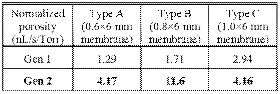
- FIG. 9 Measured porosity (top) and burst pressure (bottom) for Gen 1 and Gen 2 membranes. A minimum of seven devices was measured for each data point. From the data, it can be seen that the Gen 2 devices (i.e., the mega-rib membranes) exhibit significantly higher porosity at the expense of lower (but still acceptable) burst pressure.
- the labels “A”, “B”, and “C” denote membrane types (sizes) of 0.6x4 mm, 0.8x4 mm, and 1 .0x4 mm respectively.
- subject or “individual” is meant any member of the subphylum Chordata, including, without limitation, humans and other primates, including non-human primates such as chimpanzees and other apes and monkey species; farm animals such as cattle, sheep, pigs, goats and horses; domestic mammals such as dogs and cats; birds; and laboratory animals, including rodents such as mice, rats and guinea pigs, and the like.
- the term does not denote a particular age. Thus, both adult and newborn individuals are intended to be covered.
- the individual may be a patient in need of hemodialysis, e.g., a patient with a compromised kidney function and/or in need of dialysis, compromised heart function, and/or compromised liver function.
- substantially parallel may encompass structures that are slightly non-parallel to each other.
- a “plurality” contains at least 2 members.
- a plurality may have at least 10, at least 20, at least 30, at least 40, at least 50, at least 70, at least 90, at least 100, at least 1000, at least 10,000, at least 100,000, at least 10 6 , at least 10 7 , at least 10 8 or at least 10 9 or more members.
- Biocompatible refers to a property of a material that allows for prolonged contact with a tissue in a subject without causing significant toxicity or significant damage and optionally without causing significant damage or deterioration of the material.
- Planar when used in the context of a surface refers to a substantially flat surface as opposed to a surface that includes protrusions.
- a membrane layer as provided herein may include a first surface that is substantially planar, i.e.
- the length and width define a plane surface that is smooth as it does not include significant protrusions or depressions, and a second surface opposite the first surface that may be non-planar, e.g., having protrusions or ribs extending from the second surface which protrusions or ribs are separated by substantially smooth surface.
- the first surface of the membrane formed from the membrane layer has a plurality of nanopores extending between the first and second surface, where the nanopores are absent from the regions where the protrusions are present.
- Nanopore refers to a pore that penetrates a membrane from one side to another, where the pore has at least one lateral dimension (e.g., width and/or length, but not the height/thickness of the pore across the substrate) that is in the nanometer range, e.g., in the range of 1.0 nm to 1 ,000 nm.
- polysilicon refers to a polycrystalline form of silicon that is deposited as a thin film. It is used in microelectronics for transistors and wiring. In MEMS, polysilicon is usually used as structural material for devices. “Pumpless” as used in reference to a blood circuit is meant to refer to the absence of a pump mechanism other than the pump mechanism (e.g., the heart) that drives blood flow through the circulatory system of an individual.
- filtration refers to a process of separating particulate matter from a fluid, such as a liquid, by passing the fluid carrier through a medium that will not pass the particulates to a significant extent.
- dialysis refers to a form of filtration, or a process of selective diffusion through a membrane; it is typically used to separate low-molecular weight solutes that diffuse through the membrane from the colloidal and high-molecular weight solutes such as albumin and immunoglobulins and suspended matter such as cells which do not.
- a feed of fluid is passed over a semipermeable membrane, and a feed of dialysate is passed over the other side of that membrane; the membrane is wetted by one or both fluids, and then there is diffusive transport of solutes between the fluids.
- the composition of one fluid, the dialysate may be used to deplete the composition of the other fluid, the feed fluid, of some molecule or molecules.
- the term “ultrafiltration” refers to subjecting a fluid to filtration under pressure, where the filtered material is very small; typically, the fluid includes colloidal, dissolved solutes or very fine solid materials, and the filter is a microporous, nanoporous, or a semi- permeable medium.
- a typical medium is a membrane.
- the fluid to be filtered is referred to as the “feed fluid.”
- the feed fluid is separated into a “permeate” or “filtrate” or “ultrafiltrate,” which has been filtered through the filter, and a “retentate,” which is that part of the feed fluid which did not get filtered through the medium, or which is retained within the membrane.
- Ultrafiltration does not require a dialysate be passed over the other side of the membrane.
- dialysate is used to refer to the fluid into which low-molecular weight solutes diffuse through a membrane from another fluid (typically, the feed fluid) initially containing these solutes.
- the present disclosure provides an improved filtration membrane suitable for filtration of blood in vivo.
- the improved filtration membrane is resistant to breakage with minimal areal penalty due to presence of a system of supports on the backside of the membrane.
- the minimal areal penalty is achieved by using supports that provide a hierarchical scaffolding that comprises ribs of at least two different heights as explained in detail herein.
- Methods for making and using the filtration membrane are also provided.
- a filtration membrane suitable for filtering blood in vivo comprises a membrane section and a support section.
- the membrane section comprises a planar first surface and a second surface opposite the first surface and a plurality of nanopores, where the second surface comprises a ribbed surface.
- the ribbed second surface comprises ribs of a first height and ribs of a second height which is higher than the first height.
- the ribs of the first height define a plurality of first windows arranged in a grid pattern, the first windows comprising the plurality of nanopores.
- the ribs of the second height define a plurality of second windows arranged in a grid pattern, each of the plurality of second windows comprising a plurality of first windows.
- the support section forming a third window comprising the plurality of second windows, wherein the support section is attached to the second surface of the membrane section at a periphery of the membrane section and has a third height higher than the ribs of the second height.
- the surface area of the second surface of the membrane exposed by the third window is in the range of 0.1 mm 2 -10 mm 2 ,e.g., 0.5 mm 2 -10 mm 2 , 1 mm 2 -10 mm 2 , or 1 mm 2 -5 mm 2 .
- the ribbed second surface comprises ribs separated by planar sections where the nanopores are located. While ribs of a first height and a second height are described, it is understood that the second surface may additionally include one or more of ribs of a third height, ribs of a fourth height, and the like.
- the ribbed second surface may comprise ribs of a first height, ribs of a second height, and ribs of a third height, where the third height is higher than the second height and the second height is higher than the first height.
- the ribs of the first height define a plurality of first windows arranged in a grid pattern, the first windows comprising the plurality of nanopores.
- the ribs of the second height define a plurality of second windows arranged in a grid pattern, each of the plurality of second windows comprising a plurality of first windows.
- the ribs of the third height define a plurality of third windows arranged in a grid pattern, each of the plurality of third windows comprising a plurality of the second windows.
- the support section forming a fourth window comprising the plurality of third windows, wherein the support section is attached to the second surface of the membrane section at a periphery of the membrane section and has a fourth height higher than the ribs of the third height.
- Including additional ribs where the height of the ribs increase in a hierarchical manner may further increase the surface area of the membrane that does not need to be supported by the support section, thereby further increasing surface area of the membrane available for filtration.
- the membrane section may be formed from any suitable material, such as, materials that can be deposited or grown on a micro-or nano-thick scale.
- the membrane may be made from membrane materials such as silicon, polysilicon, silicon carbide, ultra nanocrystalline diamond, diamond-like-carbon, silicon dioxide, SU-8, titanium, silica, silicon nitride, polytetrafluorethylene, polymethylmethacrylate, polystyrene, silicone, or various other materials.
- the membrane material may be deposited by any suitable means, such as, low pressure chemical vapor deposition (LPCVD).
- the thickness of the membrane layer may be less than 5 ⁇ m, e.g., 5 ⁇ m - 0.5 ⁇ m, 4 ⁇ m- 0.5 ⁇ m, 3 ⁇ m- 0.5 ⁇ m, 2 ⁇ m- 0.5 ⁇ m, 1 ⁇ m- 0.5 ⁇ m, 0.8 ⁇ m - 0.4 ⁇ m, 0.4 ⁇ m - 0.1 ⁇ m, 0.1 ⁇ m - 0.01 ⁇ m, or 0.05 ⁇ m - 0.01 ⁇ m.
- Select examples of membrane material includes polysilicon, silicon, silicon nitride, silicon carbide, graphene and diamond and combinations thereof.
- the support section may be formed of any inert material that does not foul when exposed to aqueous fluids, such as, ultrafiltrate filtering across the membrane.
- a semiconductor material such as silicon wafer may be used for forming the support section.
- the silicon wafer that may have a variety of crystal orientations including a [100] plane orientation as listed by the Miller indices.
- support section may be formed from a substrate is formed from germanium, Group IV elements of the periodic table, lll-V compounds including gallium arsenide, ll-IV compounds including zinc tellurium, p and n doped compounds, and the like.
- the substrate may be substantially planar and may have circular or straight edges.
- the substrate may be cut into rectangular pieces or circular pieces after or prior to formation of the filtration membrane.
- the thickness of the substrate may be less than about 400 ⁇ m, about 500 ⁇ m, about 600 ⁇ m, about 700 ⁇ m, about 900 ⁇ m, etc. or more.
- the support section is formed using a silicon wafer.
- the nanopores may have a depth of about 1 ⁇ m or smaller.
- the nanopores may have a depth of about 0.9 ⁇ m to 10 nm, 0.8 ⁇ m to 100 nm, or 0.8 ⁇ m to 500 nm.
- the plurality of nanopores have a circular or slit shaped opening with a diameter or width, respectively, of 1 nm-500 nm, e.g., 1 nm-90 nm, 2 nm-50 nm, 3 nm-40 nm, 4 nm-50 nm, 4 nm-40 nm, 5 nm-50 nm, 5 nm-20 nm, 4 nm-20 nm, 7 nm-100 nm, 12 nm-20 nm, or 5 nm-10 nm.
- 1 nm-500 nm e.g., 1 nm-90 nm, 2 nm-50 nm, 3 nm-40 nm, 4 nm-50 nm, 4 nm-40 nm, 5 nm-50 nm, 5 nm-20 nm, 4 nm-20 nm, 7 nm-100 nm, 12 nm-20 nm
- the plurality of pores are slit shaped and have a width as listed herein and have a length in the range of 1 ⁇ m - 10 ⁇ m, e.g., 2 ⁇ m - 3 ⁇ m, 3 ⁇ m - 4 ⁇ m, 4 ⁇ m - 5 ⁇ m, 5 ⁇ m - 6 ⁇ m, 6 ⁇ m - 7 ⁇ m, 7 ⁇ m - 8 ⁇ m, 8 ⁇ m - 9 ⁇ m, or 9 ⁇ m - 10 ⁇ m.
- the slit shaped i.e.
- rectangular pores have a depth of 100-900 nm, a width of 3 nm-50 nm and a length of 1 micron-5 micron, e.g., a width x length x depth of 5 nm-50 nm x 1 micron-2 micron x 200 nm- 500nm.
- the depth of the pores may be defined by the thickness of the membrane which may be in the range of 0.01 micron - 100 micron.
- the nanopores are not present in regions of the membrane section that extend to form ribs. In other words, the nanopores are absent from regions of the membrane where the second surface is non-planar and extends to form the ribs. In certain aspects, the nanopores are not present in regions of the membrane section that are covered by the support section.
- the ribs of the first height extend from the second surface of the membrane and define a plurality of first windows arranged in a grid pattern. A plurality of the nanopores are present inside each of the first windows.
- panel (f) which shows ribs of a first height and regions of the membrane comprising nanopores supported by the ribs. These ribs are also visible in Fig. 7, panel (e), while the nanopores are not visible at this magnification. These ribs are also referred to as mini-ribs.
- These ribs of the first height may be arranged in a grid-like pattern such that the first windows are arrayed in a side-by-side orientation, in a two-dimensional configuration.
- the first windows may be rectangular, e.g., square shaped.
- the thickness of the ribs of the first height at the second surface of the membrane may be 0.5 ⁇ m-5 ⁇ m, e.g., 1 ⁇ m- 2.5 ⁇ m.
- the height of the ribs of the first height may be 2 ⁇ m-10 ⁇ m, 3 ⁇ m-8 ⁇ m, or 3 ⁇ m-6 ⁇ m.
- the size of each of the first windows may be 200-5000 ⁇ m 2 , e.g., 300-5000 ⁇ m 2 , 500-5000 ⁇ m 2 , 800-5000 ⁇ m 2 , 200-1000 ⁇ m 2 , 300-1000 ⁇ m 2 , 500-1000 ⁇ m 2 , or 100-5000 ⁇ m 2 .
- the first windows may be rectangular in shape.
- the length of the first windows may be 20-100 ⁇ m.
- the width of the first windows may be 10-50 ⁇ m.
- the ribs of the second height extend from the second surface of the membrane and define a plurality of second windows arranged in a grid pattern, where a plurality of the first windows are present within each of the second windows.
- panel (d) and (e) which show the ribs of the second height present around a grid-shaped pattern of the first windows (see panel (e).
- the individual first windows are not visible but the grid-shaped pattern of the second windows is visible.
- the second windows may be rectangular, e.g., square in shape.
- the number of first windows present within each of the second windows may be from about 10-100, about 10-50, about 10-40, about 10-30, or about 10-20 first windows.
- the ribs of the second height are also referred to as mega-ribs.
- the height differential between the ribs of the first height and ribs of the second height is depicted in Fig. 7, panel (b).
- the ribs of the second height may be about 5 to 50 times the height of the first ribs, e.g., 5 to 40 times, 5 to 30 times, 5 to 20 times, or 5 to 10 times the height of the first ribs, e.g., up to 6 times, 7 times, 8 times, 10 times, 15 times, 25 times, or 35 times the height of the first ribs.
- the ribs of the second height may be have a height of about 20-250 ⁇ m, e.g., 20-200 ⁇ m, 20-100 ⁇ m, 20-80 ⁇ m, 20-50 ⁇ m, or 30-50 ⁇ m.
- the thickness of the ribs of the second height at the second surface of the membrane may be 1 ⁇ m-20 ⁇ m, e.g., 1 ⁇ m- 15 ⁇ m, 5 ⁇ m-20 ⁇ m or 5 ⁇ m-15 ⁇ m.
- the ribs may be tapered in shape where the width of the ribs decreases as it extends from the membrane. In other embodiments, the ribs may be uniform in thickness.
- the ribs may be a single wall structure or may be double walled. A double wall rib requires less membrane material and hence may be used to decrease cost associated with volume of membrane materials.
- An example of ribs having a double walled structure is depicted Fig. 7, panel (f) showing double walled mini-ribs and Fig. 7, panels (a), (b), and (e) showing double walled mega-ribs.
- the support section forms a third window and is located along the periphery of the membrane.
- This third window provides access to the nanopores for a fluid flowing on the back side of the filtration membrane.
- the third window is formed by creating a cavity in the planar substrate used to form the support section, as explained in the section on method of making the filtration membrane.
- This third window may thus also be referred to as a cavity, where the walls of the cavity are formed by the support section.
- the plurality of second windows is present within the third window, e.g., as visible in Fig. 7, panel (d).
- a key feature of the disclosed filtration membrane is the increased surface of the membrane that is available for filtration due to the hierarchical support structure present on the second surface of the membrane, where the support section has a height longer than the ribs of the second height, which are longer than the ribs of the first height.
- the ribs of the first height support a section of the membrane that is planar on the first and the second surface and includes the nanopores. These ribs are also referred to herein as mini-ribs.
- These ribs define a plurality of first windows. A plurality of such first windows are in turn structurally supported by ribs of a second height higher than the first height. These ribs are also referred to herein as mega-ribs.
- mega-ribs allow for an increase in the area of the membrane that need not be supported by the support section.
- including the mega-ribs allows for positioning of the support section such that the third window formed by the support section occupies a minimal surface of the membrane per square area of the membrane. Since the areas of the membrane that are supported by the support section are not available for filtration, increasing the area of the membrane that need not be supported by the support section, increases the areas of the membrane that include nanopores at which filtration can occur.
- the ribs of the second height are substantially thinner than the support section in contact with the second surface of the membrane and hence do not block as much surface of the membrane as would be blocked if the support section was present. See Figs. 7 and 8.
- the mega-ribs are substantially lower in height as compared to the height of the support section which allows for better fluid flow on the backside if the membrane. See Fig. 4.
- the presence of the ribs of a first height and a second height allows for the area of the membrane enclosed by the third window and hence available for filtration to be increased substantially as compared to the area of the membrane exposed in the cavity as described in WO2019/222661.
- the area of the backside of the membrane exposed by the cavity is in the range of 10,000-50,000 ⁇ m 2 in WO2019/222661.
- the area of the backside of the membrane exposed in the cavity, i.e., enclosed by the third window is in the range of 1 mm 2 -10 mm 2 , 2 mm 2 -8 mm 2 , or 3 mm 2 -6 mm 2 .
- a comparison of the backside of the membrane exposed by the cavity in the membrane disclosed in WO2019/222661 to the presently disclosed membrane is provided in Fig. 8, panels (b) and (c).
- the third window may be substantially rectangular (e.g. square) in shape.
- the third window has a length of about 1 cm and a width of about 1 cm.
- the third window has a length of about 2000 ⁇ m-5000 ⁇ m and a width of 500 ⁇ m -1000 ⁇ m. In certain embodiments, the third window has a length of about 4000 ⁇ m-5000 ⁇ m and a width of about 1000 ⁇ m. In certain embodiments, the height of the third window corresponds substantially to the thickness of the substrate used for forming the support section. The third height may be 500 ⁇ m-200 ⁇ m or 500 ⁇ m-300 ⁇ m. The width of the support section in contact with the membrane section may have a thickness of about 20 ⁇ m-50 ⁇ m or 30 ⁇ m-50 ⁇ m. The plurality of second windows within the third window may include 50- 100 second windows. The membrane section and support section may be connected directly or more usually via an intermediate layer.
- the first windows, the second windows, and/or the third window and/or any additional windows that are present on the backside of the membrane may have any shape, such as, rectangular, hexagonal, trapezoidal, circular, and the like.
- the mold for the ribs may be in a rectangular, hexagonal, trapezoidal, circular, or another shape or a combination of such shapes.
- the first windows may be of one shape and the second window of another shape and the third window may have the same shape as the first or the second windows or a different shape.
- the filtration membrane described herein may be used to make a filtration device that includes a plurality of such filtration membranes arranged in a side-by-side configuration.
- the filtration device may include a plurality of filtration membranes formed using a single substrate on which a plurality of membrane sections and support sections are formed.
- a method for generating the filtration membrane for in vivo filtration of blood may include depositing a first mask in a first pattern on a first surface of a support substrate.
- the first pattern may cover and protect certain areas of the first surface and expose areas on the first surface which areas define outlines of a plurality of first rectangles arranged in a grid pattern and a plurality of second rectangles arranged in a grid pattern. Once formed each of the plurality of second rectangles include a plurality of the first rectangles.
- the method may further include depositing a second mask on the first mask such that the second mask covers the exposed areas on the first surface which areas define outlines of the first rectangular windows and does not cover the exposed areas on the first surface which areas define outlines of the second rectangular windows thereby allowing etching of the first surface to create grooves in the support substrate corresponding to the outlines of the second rectangular windows.
- a which shows substrate (bulk silicon “bulk Si”), first mask (“oxide) and second mask (“photoresist”).
- the method may further include etching the first surface to create the grooves, the grooves having a depth and a thickness; removing the second mask, wherein the removing the second mask exposes areas on the first surface defining the outlines of the plurality of first rectangles.
- the method may further include etching the first surface to increase the depth of the grooves of the plurality of the second rectangles and to create the grooves in the support substrate corresponding to the outlines of the plurality of the first rectangles such that the depth of the grooves for the second rectangles is more than that of the first rectangles.
- These grooves may also be referred to as trenches that have been created in the substrate to create a mold that is filled in. See for example, Fig. 6, panels (b) and (c) showing molds for the mega-ribs and Fig. 6 panels (d)-(e) showing molds for the min-ribs.
- the method further includes removing the first mask and depositing an intermediate layer over the support substrate.
- the intermediate layer is a thin layer deposited such that the thickness of the layer is substantially uniform, see, e.g., Fig. 6, panel (e).
- the intermediate layer in certain cases, may be deposited by creating an oxide layer on the substrate, thereby forming a thin film on the surface of the substrate.
- the intermediate layer may be a protective layer, such as, a dielectric layer.
- the intermediate layer may be formed by depositing an oxide or nitride layer over the substrate or may be grown on the substrate.
- the intermediate layer may be deposited by chemical vapor deposition (CVD) including low pressure CVD (LPCVD) and plasma enhanced CVD (PECVD), or by some other deposition means.
- CVD chemical vapor deposition
- PECVD plasma enhanced CVD
- the intermediate layer may be grown with a thermal process, such as thermal oxidation.
- the intermediate layer may include a silicon nitride, silicon oxide, silicon oxynitride, silicon carbide, or some other layer of material including other dielectric materials and combinations.
- the thickness of the intermediate layer may be about 2 ⁇ m or less, e.g., 2 ⁇ m -0.1 ⁇ m, 1 ⁇ m -0.2 ⁇ m, 1 ⁇ m -0.5 ⁇ m, or 0.8 ⁇ m -0.5 ⁇ m.
- the method may further include depositing a membrane material to fill the grooves of the first and second rectangles created in the support substrate to create a membrane comprising a planar first surface and a non-planar second surface opposite the first surface, the non-planar second surface comprising a plurality of ribs having a first height corresponding to the depth of the grooves for the first rectangles and a plurality of ribs having a second height corresponding to the depth of the grooves for the second rectangles, wherein the second height is higher than the first height. See for example, Fig. 6, panel (f) (“polyl ”).
- the method may further include creating a pattern of fine grooves in regions of the membrane (see Fig. 6, panel (g)) and depositing a sacrificial layer on the membrane (“thin oxide”).
- the sacrificial layer may be formed by oxidizing the membrane material thereby forming a thin layer of oxide on the exposed regions of the membrane.
- pore structures may be formed with a sacrificial material that may be later removed to form pores through the membrane layer.
- the nanopore structure may be formed with an etching process, or other lithography process.
- the membrane layer may be patterned with a photoresist that may be performed via e- beam, deep ultraviolet lithography, or another patterning technique that can form patterning for creating structures as described herein.
- the resist pattern may be transferred via a reactive ion etch or wet etch process onto the membrane layer.
- a sacrificial layer of material may be formed on or within the patterned membrane layer.
- the sacrificial layer may be an oxide grown via thermal oxidation that may be less than 20 nm thick. Alternatively, the layer may have a thickness of less than or about 15 nm, 10 nm, 7 nm, 5 nm, 3 nm, 1 nm, 5 angstroms, etc., or less.
- the layer of material may be conformal when grown, and thus the film may be formed via a more conformal process including high density plasma CVD (HDPCVD), or some other conformal deposition process.
- the layer may be silicon oxide, or any other material that can be subsequently removed from the membrane layer to create the membrane with nanopores.
- the method may further include filling the fine grooves with additional membrane material.
- the additional membrane material may be same material deposited initially or a different material. See, Fig. 6, panel (i) (“poly2”).
- the method may involve removing excess additional membrane material not deposited in the fine grooves (Fig.
- the nanopores may be formed in a membrane formed from a single membrane material.
- a membrane layer may be formed from a membrane material and nanopores formed therein by directly patterning and etching into the membrane layer.
- the various steps of the method may be performed by any suitable means.
- all of the steps till the creation of the third window are carried on the front side of the substrate.
- etching may be wet etching using a wet etchant such as, potassium hydroxide, tetramethylammonium, buffered hydrofluoric acid, EDP, etc.
- a wet etchant such as, potassium hydroxide, tetramethylammonium, buffered hydrofluoric acid, EDP, etc.
- the determination of when to stop the etch process can be based on a desired depth of the grooves.
- the wet etch may be isotropic or orientation selective, i.e., anisotropic.
- Etching may produce grooves with straight sides or sloped sides.
- etchants can be used that are more anisotropic and produce little or no sloping of the groove walls.
- a reactive ion etching e.g., Deep Reactive Ion Etch (DRIE), such as that relying on the Bosch process may be performed.
- DRIE Deep Reactive Ion Etch
- the substrate may act as a support section for the membrane.
- the second surface of the membrane may be exposed in the cavity in the substrate, wherein the remainder of the substrate defining the boundary of the cavity, i.e., the third window provide mechanical support to the membrane.
- the layer of sacrificial material may be selectively removed in certain areas with a subsequent photoresist patterning and etch. This may provide areas for anchoring a second membrane layer to the first membrane layer during a subsequent deposition.
- a second membrane material may be deposited filling in the anchor cavities, as well as the areas around the sacrificial layer in and around the trenches formed in the first membrane material.
- This material may be the same or a different membrane material as previously described.
- the second membrane material may also be polysilicon.
- the second membrane material layer may be planarized down at least to a level exposing the sacrificial material, and thereby forming the pore structure.
- the planarization may occur with any polishing or etching technique and can include a reactive ion etch in one example.
- the anchors may be formed and filled subsequent to depositing the second membrane material and performing a planarization.
- the process may alternatively be performed by performing an additional lithography step followed by a direct etching, such as with a reactive ion etch, followed by a specific deposition for the anchor material.
- the nanopores may also be more densely patterned by performing a series of patterning and deposition processes. For example, subsequent to the initial deposition of the membrane material, a secondary patterning step similar to that as described above may be performed. Once the secondary patterning has been performed, an additional protective layer may be deposited in a way as previously described. Following the formation of the additional protective layer, a subsequent layer of membrane material may be formed to provide the degree of pore spacing required.
- the repetitive processing may reduce the line and space pattern by 20% or more. Alternatively, the repetitive processing can reduce the line and space pattern by about 30% or more, about 40%, about 50%, about 55%, about 60%, about 65%, about 70%, about 75%, about 80%, about 85%, about 90%, etc., or more. By maintaining the protective material within the pores during fabrication, pore integrity may be maintained until a final release is performed.
- a second protective layer may be applied over the membrane materials prior to backside etching of the substrate to form the cavity and expose the membrane.
- the second protective layer may include an oxide, nitride, or another compound depending on the etching technique subsequently performed. For example, a nitride layer may be deposited if a potassium hydroxide etch is performed, and an oxide layer may be deposited if the subsequent etch includes a chemical selective to nitrogen, such as tetramethylammonium hydroxide.
- the filtration membranes may be integrated into a housing comprising pre-fabricated partial channels which in conjunction with the filtration membranes form flow path for blood flowing through the filtration device.
- the filtration membranes may be inserted into the housing comprising the pre-fabricated partial channels individually.
- a filtration membrane cassette formed by bonding filtration membranes in a spaced apart manner may be inserted into the housing and the cassette attached to the openings of the partial channels.
- the filtration device can be used in vivo or ex vivo for filtering blood of a patient in need thereof.
- Example 1 A Scalable, Hierarchical Rib Design for Larqer-area, Higher-porosity Nanoporous Membranes for the Implantable Bio-artificial Kidney
- Silicon nanoporous membranes provide the fundamental underlying technology for the develo ⁇ ment of an implantable bio-artificial kidney. These membranes, which are comprised of micromachined slit-pores that are nominally 10 nm wide, allow for high-efficiency blood filtration as well as immunoprotection for encapsulated cells. Our approach takes advantage of well- established semiconductor fabrication technology to give us precise dimensional control over pore widths, thereby enabling a highly selective filtration function and a clear path towards further miniaturization. This work builds on our prior results on “ribbed nanoporous membranes” by adding a second-level hierarchy of significantly taller “mega-ribs” to further strengthen the membranes.
- This device utilizes silicon nanoporous membranes as the fundamental underlying technology to build a biocompatible hemofilter and a renal tubule cell bioreactor, which will work together to selectively separate wastes and reabsorb salts and water [11-12] (Fig. 1).
- ANSYS Fluent 19.2 software was used (Fig. 4).
- the geometry was set up as 2D; the material used was liquid water.
- the model was steady state with a velocity inlet boundary condition of 0.02381 m/s and a static pressure outlet. The inlet region was extended to allow for fully developed flow, while blood side membrane surface urea concentration was held constant. Model performance was assessed based on water outlet concentration (urea removed).
- Fig. 5 shows FEA results for a simple (non-ribbed) 100*400 ⁇ m membrane versus a 1000*4000 ⁇ m (mega-ribbed) membrane under a constant distributed load; the results indicate that the mega-rib membrane stiffness, while up to 5X lower, could still be acceptable.
- a conformal thermal oxide liner (the “buried oxide”) is grown (Fig. 6e)
- a first polysilicon layer (“Polyl”) is deposited both filling the trenches and forming the membrane layer (Fig. 6f)
- a high-resolution lithography step prints a dense line-space array on the polysilicon.
- the pattern is then anisotropically etched into Polyl down to the buried oxide, forming a series of ridges and grooves with largely square cross- sections (Fig. 6g).
- a timed dry oxidation step forms a thin oxide (“thinOx”) on the order of 10nm (adjusted to correspond to the desired width of the eventual nanopores) on the Polyl surface, including the vertical sidewalls of the ridges (Fig. 6h).
- a second polysilicon layer (“Poly2”) is deposited to fill the grooves in Polyl (Fig. 6i). (Note that Polyl and Poly2 are separated by the thinOx layer except for periodic anchor regions not pictured here.)
- a plasma planarization step etches down the Polyl - thinOx-Poly2 stack past the original Polyl surface, revealing the vertically oriented embedded thinOx “walls” that will eventually become the nanopores (Fig. 6j).
- a passivation layer of low-temperature oxide (LTO) is deposited followed by backside DRIE and a hydrofluoric acid (HF) wet etch to remove the buried oxide and clear out the nanopores (Fig. 6k).
- LTO low-temperature oxide
- HF hydrofluoric acid
- each mega-rib actually consists of a pair of narrow, parallel trenches (Fig. 7b) to facilitate polysilicon filling without using excessive material. This reduces the amount of Polyl needed to obtain the same beam stiffness thereby reducing film stress, wafer curvature and the burden on subsequent etch steps.
- the membranes are effectively composed of an array of alternating Polyl and Poly2 elements with nanoscale slit- pores in between (Fig. 7c). Meanwhile, the backside structural hierarchy (wafer-frame ⁇ mega- rib ⁇ mini-rib ⁇ nanopores) can be seen in the zoom-in sequence of Figs. 7d-f.
- FIG. 8a A backlit optical image of a 100mm-diameter wafer with 0.8 ⁇ m-thick freestanding membranes is shown in Fig. 8a, with the wafer showing almost perfect yield. Meanwhile, the significant gain in active filter area going from Gen 1 to Gen 2 can be seen under the optical microscope (Figs. 8b-c) in the form of larger (light-transmitting) membrane regions.
Landscapes
- Chemical & Material Sciences (AREA)
- Chemical Kinetics & Catalysis (AREA)
- Inorganic Chemistry (AREA)
- Health & Medical Sciences (AREA)
- Engineering & Computer Science (AREA)
- Urology & Nephrology (AREA)
- Heart & Thoracic Surgery (AREA)
- Physics & Mathematics (AREA)
- Optics & Photonics (AREA)
- Manufacturing & Machinery (AREA)
- Life Sciences & Earth Sciences (AREA)
- Vascular Medicine (AREA)
- Anesthesiology (AREA)
- Biomedical Technology (AREA)
- Hematology (AREA)
- Emergency Medicine (AREA)
- Animal Behavior & Ethology (AREA)
- General Health & Medical Sciences (AREA)
- Public Health (AREA)
- Veterinary Medicine (AREA)
- Water Supply & Treatment (AREA)
- Separation Using Semi-Permeable Membranes (AREA)
- External Artificial Organs (AREA)
Abstract
Description

Claims
Priority Applications (5)
| Application Number | Priority Date | Filing Date | Title |
|---|---|---|---|
| JP2023508571A JP2023537072A (en) | 2020-08-07 | 2021-08-05 | Improved filtration membrane and methods of making and using same |
| EP21853113.5A EP4178712A4 (en) | 2020-08-07 | 2021-08-05 | Improved filtration membrane and methods of making and using the same |
| US18/020,031 US20230277987A1 (en) | 2020-08-07 | 2021-08-05 | Improved Filtration Membrane and Methods of Making and Using the Same |
| AU2021320873A AU2021320873A1 (en) | 2020-08-07 | 2021-08-05 | Improved filtration membrane and methods of making and using the same |
| CA3188615A CA3188615A1 (en) | 2020-08-07 | 2021-08-05 | Improved filtration membrane and methods of making and using the same |
Applications Claiming Priority (4)
| Application Number | Priority Date | Filing Date | Title |
|---|---|---|---|
| US202063063038P | 2020-08-07 | 2020-08-07 | |
| US63/063,038 | 2020-08-07 | ||
| US202063070999P | 2020-08-27 | 2020-08-27 | |
| US63/070,999 | 2020-08-27 |
Publications (1)
| Publication Number | Publication Date |
|---|---|
| WO2022031993A1 true WO2022031993A1 (en) | 2022-02-10 |
Family
ID=80117675
Family Applications (1)
| Application Number | Title | Priority Date | Filing Date |
|---|---|---|---|
| PCT/US2021/044784 Ceased WO2022031993A1 (en) | 2020-08-07 | 2021-08-05 | Improved filtration membrane and methods of making and using the same |
Country Status (6)
| Country | Link |
|---|---|
| US (1) | US20230277987A1 (en) |
| EP (1) | EP4178712A4 (en) |
| JP (1) | JP2023537072A (en) |
| AU (1) | AU2021320873A1 (en) |
| CA (1) | CA3188615A1 (en) |
| WO (1) | WO2022031993A1 (en) |
Cited By (1)
| Publication number | Priority date | Publication date | Assignee | Title |
|---|---|---|---|---|
| WO2024161379A1 (en) * | 2023-02-03 | 2024-08-08 | Medspray B.V. | Spray device and method of manufacturing the same |
Citations (4)
| Publication number | Priority date | Publication date | Assignee | Title |
|---|---|---|---|---|
| US5753014A (en) * | 1993-11-12 | 1998-05-19 | Van Rijn; Cornelis Johannes Maria | Membrane filter and a method of manufacturing the same as well as a membrane |
| US20030168396A1 (en) * | 1999-12-08 | 2003-09-11 | Jacobson James D. | Monolithic filter body and fabrication technique |
| US20050263452A1 (en) * | 1999-12-08 | 2005-12-01 | Jacobson James D | Microporous filter membrane, method of making microporous filter membrane and separator employing microporous filter membranes |
| WO2019222661A1 (en) | 2018-05-18 | 2019-11-21 | The Regents Of The University Of California | In vivo blood filtration membranes and devices |
Family Cites Families (10)
| Publication number | Priority date | Publication date | Assignee | Title |
|---|---|---|---|---|
| JPH03146120A (en) * | 1989-11-01 | 1991-06-21 | Terumo Corp | Filtration membrane and filtration apparatus using the membrane |
| WO2003000483A1 (en) * | 2001-06-23 | 2003-01-03 | Spaeth Bernd | Body with improved surface properties |
| JP2007330757A (en) * | 2006-05-18 | 2007-12-27 | Sekisui Chem Co Ltd | Blood separation device |
| TWI395610B (en) * | 2010-12-24 | 2013-05-11 | Univ Nat Cheng Kung | Liquid filtering device and filtering method using the same |
| JP5390578B2 (en) * | 2011-10-24 | 2014-01-15 | 日機装株式会社 | Air trap chamber |
| US20160007119A1 (en) * | 2014-04-23 | 2016-01-07 | Knowles Electronics, Llc | Diaphragm Stiffener |
| WO2016117541A1 (en) * | 2015-01-22 | 2016-07-28 | 株式会社村田製作所 | Void array structure and method for producing same |
| JP6394804B2 (en) * | 2015-06-22 | 2018-09-26 | 株式会社村田製作所 | Filtration filter |
| JP2019195757A (en) * | 2018-05-08 | 2019-11-14 | イビデン株式会社 | Filter membrane |
| JP2020044500A (en) * | 2018-09-19 | 2020-03-26 | イビデン株式会社 | Filter membrane and filtration method using the filter membrane |
-
2021
- 2021-08-05 EP EP21853113.5A patent/EP4178712A4/en active Pending
- 2021-08-05 JP JP2023508571A patent/JP2023537072A/en active Pending
- 2021-08-05 WO PCT/US2021/044784 patent/WO2022031993A1/en not_active Ceased
- 2021-08-05 AU AU2021320873A patent/AU2021320873A1/en active Pending
- 2021-08-05 CA CA3188615A patent/CA3188615A1/en active Pending
- 2021-08-05 US US18/020,031 patent/US20230277987A1/en active Pending
Patent Citations (4)
| Publication number | Priority date | Publication date | Assignee | Title |
|---|---|---|---|---|
| US5753014A (en) * | 1993-11-12 | 1998-05-19 | Van Rijn; Cornelis Johannes Maria | Membrane filter and a method of manufacturing the same as well as a membrane |
| US20030168396A1 (en) * | 1999-12-08 | 2003-09-11 | Jacobson James D. | Monolithic filter body and fabrication technique |
| US20050263452A1 (en) * | 1999-12-08 | 2005-12-01 | Jacobson James D | Microporous filter membrane, method of making microporous filter membrane and separator employing microporous filter membranes |
| WO2019222661A1 (en) | 2018-05-18 | 2019-11-21 | The Regents Of The University Of California | In vivo blood filtration membranes and devices |
Non-Patent Citations (21)
| Title |
|---|
| A.A. HAMZAHH. E. ZAINAL ABIDINB. YEOP MAJLISM. MOHD NORA. ISMARDIG. SUGANDIT. Y. TIONGC. F. DEEJ. YUNAS: "Electrochemically deposited and etched membranes with precisely sized micropores for biological fluids microfiltration", J. MICROMECH MICROENG, vol. 23, 2013, pages 074007 |
| A.C. HOOGERWERFC. HINDERLINGS. KRISHNAMOORTHYC. HIBERTV. SPASSOVT. OVERSTOLZ: "Fabrication of Reinforced Nanoporous Membranes", PROC. TRANSDUCERS, 2007 |
| B.J. LUTZENBERGERD. DICKENSHEETS: "Fabrication and modeling of rib-stiffened thin films", J. MICROMECH. MICROENG., vol. 19, 2009, XP020164981, DOI: 10.1088/0960-1317/19/9/095003 |
| B.W. CHUIP. TAHERI-TEHRANIN. WRIGHTJ. LYS. ROY: "Ribbed Nanoporous Membranes for the Implantable Bio-artificial Kidney", HILTON HEAD SOLID-STATE SENSOR & ACTUATOR WORKSHOP, 2018 |
| CHUI BENJAMIN W.; WRIGHT NATHAN J.; LY JIMMY; MAGINNIS DAVID A.; HANIFF TARIQ M.; BLAHA CHARLES; FISSELL WILLIAM H.; ROY SHUVO: "A Scalable, Hierarchical Rib Design for Larger-Area, Higher-Porosity Nanoporous Membranes for the Implantable Bio-Artificial Kidney", JOURNAL OF MICROELECTROMECHANICAL SYSTEMS., IEEE SERVICE CENTER, US, vol. 29, no. 5, 1 October 2020 (2020-10-01), US , pages 762 - 768, XP011813335, ISSN: 1057-7157, DOI: 10.1109/JMEMS.2020.3013606 * |
| D.B.N. LEEM. ROBERTS: "A peritoneal-based automated wearable artificial kidney", CLIN. EXP. NEPHROL., vol. 12, 2008, pages 171 - 180, XP019595456 |
| D.J. DE JAGERJ.J., CARREROM. VERDUIJNP. RAVANIJ. DE MEESTERJ.G.HEAFP. FINNEA.J. HOITSMAJ. PASCUALF. JARRAYA: "Cardiovascular and noncardiovascular mortality among patients starting dialysis", JAMA, vol. 302, 2009, pages 1782 - 9 |
| E. O'LONEM. CONNORSP MASSONS. WUP.J. KELLYD. GILLESPIED. PARKERW. WHITELEYG.F. STRIPPOLIS.C. PALMER: "Cognition in People With End-Stage Kidney Disease Treated With Hemodialysis: A Systematic Review and Meta-analysis", AM. J. KIDNEY DIS. OFF. J. NATL. KIDNEY FOUND., vol. 67, 2016, pages 925 - 935, XP029552390, DOI: 10.1053/j.ajkd.2015.12.028 |
| E.A. ROSSM.J. WILLIAMST. HAMAZAKIN. TERADAW.L. CLAPPC. ADING.W. ELLISONM. JORGENSENC.D. BATICH: "Embryonic stem cells proliferate and differentiate when seeded into kidney scaffolds", J. AM. SOC. NEPHROL. JASN, vol. 20, 2009, pages 2338 - 2347, XP055074894, DOI: 10.1681/ASN.2008111196 |
| H.D. HUMESD.A. BUFFINGTONL. LOUS. ABRISHAMIM. WANGJ. XIAW.H. FISSELL: "Cell therapy with a tissue-engineered kidney reduces the multiple-organ consequences of septic shock", CRIT. CARE MED., vol. 31, 2003, pages 2421 - 2428 |
| H.D. HUMESD.A. BUFFINGTONS.M. MACKAYA.J. FUNKEW.F. WEITZEL: "Replacement of renal function in uremic animals with a tissue-engineered kidney", NAT. BIOTECHNOL., vol. 17, 1999, pages 451 - 455, XP009162214, DOI: 10.1038/8626 |
| J. DRAKEH. JERMAN: "A Micromachined Torsional Mirror for Track Following in Magneto-Optical Disk Drives", PROC. HILTON HEAD SOLID-STATE SENSORS AND ACTUATORS WORKSHOP, 2000 |
| J.D. KOPPLE: "Physical performance and all-cause mortality in CKD", J. AM. SOC. NEPHROL. JASN, vol. 24, 2013, pages 689 - 690 |
| M. HAJJ-HASSANM.C. CHEUNGV.P. CHODAVARAPU: "Ultra-thin porous silicon membranes fabricated using dry etching", MICRO & NANO LETT., vol. 6, 2011, pages 226 - 228, XP006038230, DOI: 10.1049/MNL:20100233 |
| M. SALANIS. ROYW.H. FISSELL: "Innovations in Wearable and Implantable Artificial Kidneys", AM. J. KIDNEY DIS. OFF. J. NATL. KIDNEY FOUND., vol. 72, 2018, pages 745 - 751, XP085531474, DOI: 10.1053/j.ajkd.2018.06.005 |
| M. TAKASATOP.X. ERH.S. CHIUB. MAIERG.J. BAILLIEC. FERGUSONR.G. PARTONE.J. WOLVETANGM.S. ROOSTS.M. CHUVA DE SOUSA LOPES: "Kidney organoids from human iPS cells contain multiple lineages and model human nephrogenesis", NATURE, vol. 536, 2016, pages 238 |
| S. KIM, B. FEINBERG, R. KANT, B.W. CHUI, K. GOLDMAN, J. PARK, W. MOSES, C. BLAHA, Z. LQBAL, C. CHOW, N. WRIGHT, W.H. FISSELL, A. Z: "Diffusive Silicon Nanopore Membranes for Hemodialysis Applications", PLOS, 2016 |
| S. ROYA. DUBNISHEVAA. ELDRIDGEA.J. FLEISCHMANK.G. GOLDMANH.D. HUMESA.L. ZYDNEYW.H. FISSELL: "Silicon Nanopore Membrane Technology for an Implantable Artificial Kidney", PROC. TRANSDUCERS, 2009 |
| T.A. DESAID.J. HANSFORDL. LEONIM. ESSENPREISM. FERRARI: "Nanoporous antifouling silicon membranes for bio-sensor applications", BIOSENSORS AND BIOELECTRONICS, vol. 15, 2000, pages 453 - 462 |
| V. GURAA.S. MACYM. BEIZAIC. EZONT.A. GOLPER: "Technical breakthroughs in the wearable artificial kidney (WAK", CLIN. J. AM. SOC. NEPHROL. CJASN, vol. 4, 2009, pages 1441 - 1448, XP055548016, DOI: 10.2215/CJN.02790409 |
| W.H. FISSELLS. ROY: "The implantable artificial kidney", SEMIN. DIAL., vol. 22, 2009, pages 665 - 670 |
Cited By (2)
| Publication number | Priority date | Publication date | Assignee | Title |
|---|---|---|---|---|
| WO2024161379A1 (en) * | 2023-02-03 | 2024-08-08 | Medspray B.V. | Spray device and method of manufacturing the same |
| NL2034082B1 (en) * | 2023-02-03 | 2024-08-23 | Medspray B V | Spray device and method of manufacturing the same |
Also Published As
| Publication number | Publication date |
|---|---|
| AU2021320873A1 (en) | 2023-03-09 |
| EP4178712A1 (en) | 2023-05-17 |
| EP4178712A4 (en) | 2024-06-05 |
| US20230277987A1 (en) | 2023-09-07 |
| CA3188615A1 (en) | 2022-02-10 |
| JP2023537072A (en) | 2023-08-30 |
Similar Documents
| Publication | Publication Date | Title |
|---|---|---|
| US9403126B2 (en) | Ultrafiltration membrane, device, bioartificial organ, and related methods | |
| US20250214040A1 (en) | In Vivo Blood Filtration Membranes and Devices | |
| EP2493597B1 (en) | Microfluidic device for blood dialysis | |
| EP0831963B1 (en) | Microfabricated porous membranes with bulk support | |
| US5985164A (en) | Method for forming a filter | |
| Warkiani et al. | Isoporous micro/nanoengineered membranes | |
| US7442303B2 (en) | Microporous filter membrane, method of making microporous filter membrane and separator employing microporous filter membranes | |
| JP2016172019A (en) | Microfabricated artificial lung assist device, and methods of use and manufacture thereof | |
| Chui et al. | A scalable, hierarchical rib design for larger-area, higher-porosity nanoporous membranes for the implantable bio-artificial kidney | |
| JP2019034300A (en) | Low resistance micromachined filter | |
| WO2015039118A1 (en) | Microfluidic organ assist device incorporating boundary layer disrupters | |
| US20230277987A1 (en) | Improved Filtration Membrane and Methods of Making and Using the Same | |
| US12324876B2 (en) | Fluid reactors | |
| JP6678238B2 (en) | Method of making a fluid cavity by transmembrane etching through a porous membrane and structures produced thereby and uses of such structures | |
| US20070119781A1 (en) | Apparatus and method for enhanced hemodialysis performance | |
| TW200405824A (en) | Monolithic filter body and fabrication technique | |
| Mustafa et al. | Design and Fabrication of Uniform Aluminium Pores for Planar Microfiltration System. | |
| Lu | Development of porous ceramic membranes for potential use in artificial kidney | |
| Chui et al. | ROBUST “RIBBED” NANOPOROUS MEMBRANES FOR IMPLANTABLE BIO-ARTIFICIAL KIDNEYS |
Legal Events
| Date | Code | Title | Description |
|---|---|---|---|
| 121 | Ep: the epo has been informed by wipo that ep was designated in this application |
Ref document number: 21853113 Country of ref document: EP Kind code of ref document: A1 |
|
| ENP | Entry into the national phase |
Ref document number: 2023508571 Country of ref document: JP Kind code of ref document: A Ref document number: 3188615 Country of ref document: CA |
|
| ENP | Entry into the national phase |
Ref document number: 2021853113 Country of ref document: EP Effective date: 20230208 |
|
| NENP | Non-entry into the national phase |
Ref country code: DE |
|
| ENP | Entry into the national phase |
Ref document number: 2021320873 Country of ref document: AU Date of ref document: 20210805 Kind code of ref document: A |