WO2022034905A1 - ステント - Google Patents
ステント Download PDFInfo
- Publication number
- WO2022034905A1 WO2022034905A1 PCT/JP2021/029676 JP2021029676W WO2022034905A1 WO 2022034905 A1 WO2022034905 A1 WO 2022034905A1 JP 2021029676 W JP2021029676 W JP 2021029676W WO 2022034905 A1 WO2022034905 A1 WO 2022034905A1
- Authority
- WO
- WIPO (PCT)
- Prior art keywords
- stent
- leg
- leg portion
- length
- adjacent
- Prior art date
- Legal status (The legal status is an assumption and is not a legal conclusion. Google has not performed a legal analysis and makes no representation as to the accuracy of the status listed.)
- Ceased
Links
Images
















Classifications
-
- A—HUMAN NECESSITIES
- A61—MEDICAL OR VETERINARY SCIENCE; HYGIENE
- A61F—FILTERS IMPLANTABLE INTO BLOOD VESSELS; PROSTHESES; DEVICES PROVIDING PATENCY TO, OR PREVENTING COLLAPSING OF, TUBULAR STRUCTURES OF THE BODY, e.g. STENTS; ORTHOPAEDIC, NURSING OR CONTRACEPTIVE DEVICES; FOMENTATION; TREATMENT OR PROTECTION OF EYES OR EARS; BANDAGES, DRESSINGS OR ABSORBENT PADS; FIRST-AID KITS
- A61F2/00—Filters implantable into blood vessels; Prostheses, i.e. artificial substitutes or replacements for parts of the body; Appliances for connecting them with the body; Devices providing patency to, or preventing collapsing of, tubular structures of the body, e.g. stents
- A61F2/82—Devices providing patency to, or preventing collapsing of, tubular structures of the body, e.g. stents
- A61F2/86—Stents in a form characterised by the wire-like elements; Stents in the form characterised by a net-like or mesh-like structure
- A61F2/88—Stents in a form characterised by the wire-like elements; Stents in the form characterised by a net-like or mesh-like structure the wire-like elements formed as helical or spiral coils
-
- A—HUMAN NECESSITIES
- A61—MEDICAL OR VETERINARY SCIENCE; HYGIENE
- A61F—FILTERS IMPLANTABLE INTO BLOOD VESSELS; PROSTHESES; DEVICES PROVIDING PATENCY TO, OR PREVENTING COLLAPSING OF, TUBULAR STRUCTURES OF THE BODY, e.g. STENTS; ORTHOPAEDIC, NURSING OR CONTRACEPTIVE DEVICES; FOMENTATION; TREATMENT OR PROTECTION OF EYES OR EARS; BANDAGES, DRESSINGS OR ABSORBENT PADS; FIRST-AID KITS
- A61F2/00—Filters implantable into blood vessels; Prostheses, i.e. artificial substitutes or replacements for parts of the body; Appliances for connecting them with the body; Devices providing patency to, or preventing collapsing of, tubular structures of the body, e.g. stents
- A61F2/82—Devices providing patency to, or preventing collapsing of, tubular structures of the body, e.g. stents
- A61F2/86—Stents in a form characterised by the wire-like elements; Stents in the form characterised by a net-like or mesh-like structure
- A61F2/90—Stents in a form characterised by the wire-like elements; Stents in the form characterised by a net-like or mesh-like structure characterised by a net-like or mesh-like structure
-
- A—HUMAN NECESSITIES
- A61—MEDICAL OR VETERINARY SCIENCE; HYGIENE
- A61F—FILTERS IMPLANTABLE INTO BLOOD VESSELS; PROSTHESES; DEVICES PROVIDING PATENCY TO, OR PREVENTING COLLAPSING OF, TUBULAR STRUCTURES OF THE BODY, e.g. STENTS; ORTHOPAEDIC, NURSING OR CONTRACEPTIVE DEVICES; FOMENTATION; TREATMENT OR PROTECTION OF EYES OR EARS; BANDAGES, DRESSINGS OR ABSORBENT PADS; FIRST-AID KITS
- A61F2/00—Filters implantable into blood vessels; Prostheses, i.e. artificial substitutes or replacements for parts of the body; Appliances for connecting them with the body; Devices providing patency to, or preventing collapsing of, tubular structures of the body, e.g. stents
- A61F2/82—Devices providing patency to, or preventing collapsing of, tubular structures of the body, e.g. stents
- A61F2/86—Stents in a form characterised by the wire-like elements; Stents in the form characterised by a net-like or mesh-like structure
- A61F2/89—Stents in a form characterised by the wire-like elements; Stents in the form characterised by a net-like or mesh-like structure the wire-like elements comprising two or more adjacent rings flexibly connected by separate members
-
- A—HUMAN NECESSITIES
- A61—MEDICAL OR VETERINARY SCIENCE; HYGIENE
- A61F—FILTERS IMPLANTABLE INTO BLOOD VESSELS; PROSTHESES; DEVICES PROVIDING PATENCY TO, OR PREVENTING COLLAPSING OF, TUBULAR STRUCTURES OF THE BODY, e.g. STENTS; ORTHOPAEDIC, NURSING OR CONTRACEPTIVE DEVICES; FOMENTATION; TREATMENT OR PROTECTION OF EYES OR EARS; BANDAGES, DRESSINGS OR ABSORBENT PADS; FIRST-AID KITS
- A61F2/00—Filters implantable into blood vessels; Prostheses, i.e. artificial substitutes or replacements for parts of the body; Appliances for connecting them with the body; Devices providing patency to, or preventing collapsing of, tubular structures of the body, e.g. stents
- A61F2/82—Devices providing patency to, or preventing collapsing of, tubular structures of the body, e.g. stents
- A61F2/86—Stents in a form characterised by the wire-like elements; Stents in the form characterised by a net-like or mesh-like structure
- A61F2/90—Stents in a form characterised by the wire-like elements; Stents in the form characterised by a net-like or mesh-like structure characterised by a net-like or mesh-like structure
- A61F2/91—Stents in a form characterised by the wire-like elements; Stents in the form characterised by a net-like or mesh-like structure characterised by a net-like or mesh-like structure made from perforated sheets or tubes, e.g. perforated by laser cuts or etched holes
- A61F2/915—Stents in a form characterised by the wire-like elements; Stents in the form characterised by a net-like or mesh-like structure characterised by a net-like or mesh-like structure made from perforated sheets or tubes, e.g. perforated by laser cuts or etched holes with bands having a meander structure, adjacent bands being connected to each other
-
- A—HUMAN NECESSITIES
- A61—MEDICAL OR VETERINARY SCIENCE; HYGIENE
- A61F—FILTERS IMPLANTABLE INTO BLOOD VESSELS; PROSTHESES; DEVICES PROVIDING PATENCY TO, OR PREVENTING COLLAPSING OF, TUBULAR STRUCTURES OF THE BODY, e.g. STENTS; ORTHOPAEDIC, NURSING OR CONTRACEPTIVE DEVICES; FOMENTATION; TREATMENT OR PROTECTION OF EYES OR EARS; BANDAGES, DRESSINGS OR ABSORBENT PADS; FIRST-AID KITS
- A61F2/00—Filters implantable into blood vessels; Prostheses, i.e. artificial substitutes or replacements for parts of the body; Appliances for connecting them with the body; Devices providing patency to, or preventing collapsing of, tubular structures of the body, e.g. stents
- A61F2/82—Devices providing patency to, or preventing collapsing of, tubular structures of the body, e.g. stents
- A61F2002/825—Devices providing patency to, or preventing collapsing of, tubular structures of the body, e.g. stents having longitudinal struts
-
- A—HUMAN NECESSITIES
- A61—MEDICAL OR VETERINARY SCIENCE; HYGIENE
- A61F—FILTERS IMPLANTABLE INTO BLOOD VESSELS; PROSTHESES; DEVICES PROVIDING PATENCY TO, OR PREVENTING COLLAPSING OF, TUBULAR STRUCTURES OF THE BODY, e.g. STENTS; ORTHOPAEDIC, NURSING OR CONTRACEPTIVE DEVICES; FOMENTATION; TREATMENT OR PROTECTION OF EYES OR EARS; BANDAGES, DRESSINGS OR ABSORBENT PADS; FIRST-AID KITS
- A61F2/00—Filters implantable into blood vessels; Prostheses, i.e. artificial substitutes or replacements for parts of the body; Appliances for connecting them with the body; Devices providing patency to, or preventing collapsing of, tubular structures of the body, e.g. stents
- A61F2/82—Devices providing patency to, or preventing collapsing of, tubular structures of the body, e.g. stents
- A61F2002/828—Means for connecting a plurality of stents allowing flexibility of the whole structure
-
- A—HUMAN NECESSITIES
- A61—MEDICAL OR VETERINARY SCIENCE; HYGIENE
- A61F—FILTERS IMPLANTABLE INTO BLOOD VESSELS; PROSTHESES; DEVICES PROVIDING PATENCY TO, OR PREVENTING COLLAPSING OF, TUBULAR STRUCTURES OF THE BODY, e.g. STENTS; ORTHOPAEDIC, NURSING OR CONTRACEPTIVE DEVICES; FOMENTATION; TREATMENT OR PROTECTION OF EYES OR EARS; BANDAGES, DRESSINGS OR ABSORBENT PADS; FIRST-AID KITS
- A61F2/00—Filters implantable into blood vessels; Prostheses, i.e. artificial substitutes or replacements for parts of the body; Appliances for connecting them with the body; Devices providing patency to, or preventing collapsing of, tubular structures of the body, e.g. stents
- A61F2/82—Devices providing patency to, or preventing collapsing of, tubular structures of the body, e.g. stents
- A61F2/86—Stents in a form characterised by the wire-like elements; Stents in the form characterised by a net-like or mesh-like structure
- A61F2/90—Stents in a form characterised by the wire-like elements; Stents in the form characterised by a net-like or mesh-like structure characterised by a net-like or mesh-like structure
- A61F2/91—Stents in a form characterised by the wire-like elements; Stents in the form characterised by a net-like or mesh-like structure characterised by a net-like or mesh-like structure made from perforated sheets or tubes, e.g. perforated by laser cuts or etched holes
- A61F2/915—Stents in a form characterised by the wire-like elements; Stents in the form characterised by a net-like or mesh-like structure characterised by a net-like or mesh-like structure made from perforated sheets or tubes, e.g. perforated by laser cuts or etched holes with bands having a meander structure, adjacent bands being connected to each other
- A61F2002/91533—Stents in a form characterised by the wire-like elements; Stents in the form characterised by a net-like or mesh-like structure characterised by a net-like or mesh-like structure made from perforated sheets or tubes, e.g. perforated by laser cuts or etched holes with bands having a meander structure, adjacent bands being connected to each other characterised by the phase between adjacent bands
-
- A—HUMAN NECESSITIES
- A61—MEDICAL OR VETERINARY SCIENCE; HYGIENE
- A61F—FILTERS IMPLANTABLE INTO BLOOD VESSELS; PROSTHESES; DEVICES PROVIDING PATENCY TO, OR PREVENTING COLLAPSING OF, TUBULAR STRUCTURES OF THE BODY, e.g. STENTS; ORTHOPAEDIC, NURSING OR CONTRACEPTIVE DEVICES; FOMENTATION; TREATMENT OR PROTECTION OF EYES OR EARS; BANDAGES, DRESSINGS OR ABSORBENT PADS; FIRST-AID KITS
- A61F2/00—Filters implantable into blood vessels; Prostheses, i.e. artificial substitutes or replacements for parts of the body; Appliances for connecting them with the body; Devices providing patency to, or preventing collapsing of, tubular structures of the body, e.g. stents
- A61F2/82—Devices providing patency to, or preventing collapsing of, tubular structures of the body, e.g. stents
- A61F2/86—Stents in a form characterised by the wire-like elements; Stents in the form characterised by a net-like or mesh-like structure
- A61F2/90—Stents in a form characterised by the wire-like elements; Stents in the form characterised by a net-like or mesh-like structure characterised by a net-like or mesh-like structure
- A61F2/91—Stents in a form characterised by the wire-like elements; Stents in the form characterised by a net-like or mesh-like structure characterised by a net-like or mesh-like structure made from perforated sheets or tubes, e.g. perforated by laser cuts or etched holes
- A61F2/915—Stents in a form characterised by the wire-like elements; Stents in the form characterised by a net-like or mesh-like structure characterised by a net-like or mesh-like structure made from perforated sheets or tubes, e.g. perforated by laser cuts or etched holes with bands having a meander structure, adjacent bands being connected to each other
- A61F2002/91533—Stents in a form characterised by the wire-like elements; Stents in the form characterised by a net-like or mesh-like structure characterised by a net-like or mesh-like structure made from perforated sheets or tubes, e.g. perforated by laser cuts or etched holes with bands having a meander structure, adjacent bands being connected to each other characterised by the phase between adjacent bands
- A61F2002/91541—Adjacent bands are arranged out of phase
-
- A—HUMAN NECESSITIES
- A61—MEDICAL OR VETERINARY SCIENCE; HYGIENE
- A61F—FILTERS IMPLANTABLE INTO BLOOD VESSELS; PROSTHESES; DEVICES PROVIDING PATENCY TO, OR PREVENTING COLLAPSING OF, TUBULAR STRUCTURES OF THE BODY, e.g. STENTS; ORTHOPAEDIC, NURSING OR CONTRACEPTIVE DEVICES; FOMENTATION; TREATMENT OR PROTECTION OF EYES OR EARS; BANDAGES, DRESSINGS OR ABSORBENT PADS; FIRST-AID KITS
- A61F2/00—Filters implantable into blood vessels; Prostheses, i.e. artificial substitutes or replacements for parts of the body; Appliances for connecting them with the body; Devices providing patency to, or preventing collapsing of, tubular structures of the body, e.g. stents
- A61F2/82—Devices providing patency to, or preventing collapsing of, tubular structures of the body, e.g. stents
- A61F2/86—Stents in a form characterised by the wire-like elements; Stents in the form characterised by a net-like or mesh-like structure
- A61F2/90—Stents in a form characterised by the wire-like elements; Stents in the form characterised by a net-like or mesh-like structure characterised by a net-like or mesh-like structure
- A61F2/91—Stents in a form characterised by the wire-like elements; Stents in the form characterised by a net-like or mesh-like structure characterised by a net-like or mesh-like structure made from perforated sheets or tubes, e.g. perforated by laser cuts or etched holes
- A61F2/915—Stents in a form characterised by the wire-like elements; Stents in the form characterised by a net-like or mesh-like structure characterised by a net-like or mesh-like structure made from perforated sheets or tubes, e.g. perforated by laser cuts or etched holes with bands having a meander structure, adjacent bands being connected to each other
- A61F2002/9155—Adjacent bands being connected to each other
-
- A—HUMAN NECESSITIES
- A61—MEDICAL OR VETERINARY SCIENCE; HYGIENE
- A61F—FILTERS IMPLANTABLE INTO BLOOD VESSELS; PROSTHESES; DEVICES PROVIDING PATENCY TO, OR PREVENTING COLLAPSING OF, TUBULAR STRUCTURES OF THE BODY, e.g. STENTS; ORTHOPAEDIC, NURSING OR CONTRACEPTIVE DEVICES; FOMENTATION; TREATMENT OR PROTECTION OF EYES OR EARS; BANDAGES, DRESSINGS OR ABSORBENT PADS; FIRST-AID KITS
- A61F2/00—Filters implantable into blood vessels; Prostheses, i.e. artificial substitutes or replacements for parts of the body; Appliances for connecting them with the body; Devices providing patency to, or preventing collapsing of, tubular structures of the body, e.g. stents
- A61F2/82—Devices providing patency to, or preventing collapsing of, tubular structures of the body, e.g. stents
- A61F2/86—Stents in a form characterised by the wire-like elements; Stents in the form characterised by a net-like or mesh-like structure
- A61F2/90—Stents in a form characterised by the wire-like elements; Stents in the form characterised by a net-like or mesh-like structure characterised by a net-like or mesh-like structure
- A61F2/91—Stents in a form characterised by the wire-like elements; Stents in the form characterised by a net-like or mesh-like structure characterised by a net-like or mesh-like structure made from perforated sheets or tubes, e.g. perforated by laser cuts or etched holes
- A61F2/915—Stents in a form characterised by the wire-like elements; Stents in the form characterised by a net-like or mesh-like structure characterised by a net-like or mesh-like structure made from perforated sheets or tubes, e.g. perforated by laser cuts or etched holes with bands having a meander structure, adjacent bands being connected to each other
- A61F2002/9155—Adjacent bands being connected to each other
- A61F2002/91583—Adjacent bands being connected to each other by a bridge, whereby at least one of its ends is connected along the length of a strut between two consecutive apices within a band
-
- A—HUMAN NECESSITIES
- A61—MEDICAL OR VETERINARY SCIENCE; HYGIENE
- A61F—FILTERS IMPLANTABLE INTO BLOOD VESSELS; PROSTHESES; DEVICES PROVIDING PATENCY TO, OR PREVENTING COLLAPSING OF, TUBULAR STRUCTURES OF THE BODY, e.g. STENTS; ORTHOPAEDIC, NURSING OR CONTRACEPTIVE DEVICES; FOMENTATION; TREATMENT OR PROTECTION OF EYES OR EARS; BANDAGES, DRESSINGS OR ABSORBENT PADS; FIRST-AID KITS
- A61F2250/00—Special features of prostheses classified in groups A61F2/00 - A61F2/26 or A61F2/82 or A61F9/00 or A61F11/00 or subgroups thereof
- A61F2250/0014—Special features of prostheses classified in groups A61F2/00 - A61F2/26 or A61F2/82 or A61F9/00 or A61F11/00 or subgroups thereof having different values of a given property or geometrical feature, e.g. mechanical property or material property, at different locations within the same prosthesis
- A61F2250/0029—Special features of prostheses classified in groups A61F2/00 - A61F2/26 or A61F2/82 or A61F9/00 or A61F11/00 or subgroups thereof having different values of a given property or geometrical feature, e.g. mechanical property or material property, at different locations within the same prosthesis differing in bending or flexure capacity
-
- A—HUMAN NECESSITIES
- A61—MEDICAL OR VETERINARY SCIENCE; HYGIENE
- A61F—FILTERS IMPLANTABLE INTO BLOOD VESSELS; PROSTHESES; DEVICES PROVIDING PATENCY TO, OR PREVENTING COLLAPSING OF, TUBULAR STRUCTURES OF THE BODY, e.g. STENTS; ORTHOPAEDIC, NURSING OR CONTRACEPTIVE DEVICES; FOMENTATION; TREATMENT OR PROTECTION OF EYES OR EARS; BANDAGES, DRESSINGS OR ABSORBENT PADS; FIRST-AID KITS
- A61F2250/00—Special features of prostheses classified in groups A61F2/00 - A61F2/26 or A61F2/82 or A61F9/00 or A61F11/00 or subgroups thereof
- A61F2250/0058—Additional features; Implant or prostheses properties not otherwise provided for
- A61F2250/0096—Markers and sensors for detecting a position or changes of a position of an implant, e.g. RF sensors, ultrasound markers
- A61F2250/0098—Markers and sensors for detecting a position or changes of a position of an implant, e.g. RF sensors, ultrasound markers radio-opaque, e.g. radio-opaque markers
Definitions
- the present invention relates to a stent placed in the luminal structure of a living body to dilate the luminal.
- a reticulated cylindrical stent is used to ensure patency of the lesion site by dilating the lumen of the stenosis.
- the above-mentioned biological organs often have a locally bent or tapered structure (that is, a tubular structure in which the luminal cross-sectional diameter is locally different in the axial direction).
- a stent with high conformability that can flexibly adapt to such a complicated vascular structure is desired.
- stents have also been applied to cerebrovascular treatment.
- the cerebrovascular system has a complex structure among the tubular organs of the living body. In the cerebrovascular system, there are many sites that are bent or have a tapered structure. Therefore, the stent requires particularly high shape followability.
- the structure of the stent is generally classified into two types, an open cell type and a closed cell type. Since an open-cell structure stent exhibits extremely flexible mechanical properties in the longitudinal axis direction, it has high shape followability and has been considered to be effective as a stent structure to be placed in a bent tubular organ. However, in such an open-cell structure stent, a part of the stent strut may flare out outward in the radial direction at the time of bending. Therefore, when the stent is placed, the tubular organ of the living body such as a blood vessel There is a risk of damaging the tissue.
- the closed-cell structure stent described above does not have a risk of the stent strut protruding outward in the radial direction of the stent, but structurally, it tends to lack shape followability.
- a spiral stent has been proposed as a technique for exhibiting high flexibility while being a stent having a closed cell structure (see, for example, Patent Document 1).
- the stent of Patent Document 1 includes a spiral ring having a wavy pattern and a coiled element connecting adjacent rings in the deployed state.
- the axial direction axial direction, central axial direction
- the radial direction direction perpendicular to the axial direction
- the flexibility in the axial direction means the rigidity or the ease of bending with respect to the bending along the axial direction, and in order to flexibly bend along the axial direction and adapt to the bending site of the tubular organ of the living body. It is a necessary characteristic.
- radial flexibility means rigidity or ease of expansion / contraction in the direction perpendicular to the axial direction, and the radius of the stent along the shape of the outer wall of the luminal structure of the tubular organ of the living body. It is a property required to flexibly change and bring the stent into close contact with the outer wall of the luminal structure.
- a stent provided with a spiral annular body having a wavy pattern and a coiled element connecting them has higher shape followability than a conventional closed cell type stent. is doing.
- a so-called “kink” phenomenon occurs in the cell structure of the stent of Patent Document 1, when the radius of bending becomes small to some extent, a so-called “kink” phenomenon occurs.
- Kink means that the cross section of the stent is crushed into a substantially elliptical shape.
- a thrombus may accumulate in the gap between the inner wall of the tubular organ and the stent, which may obstruct the flow of liquid such as blood in the tubular organ.
- the stent is required not only to have shape followability but also to maintain the shape of the cross section in a circular shape when bent.
- the degree to which the shape of the cross section is kept circular when the stent is bent is referred to as "patency".
- An object of the present invention is to provide a stent having high patency against flexion.
- the present invention comprises a plurality of wavy pattern bodies having a wavy pattern and arranged side by side in the axial direction, and a plurality of connecting elements arranged around the axis and connecting the adjacent wavy pattern bodies.
- a stent to be inserted into a catheter in a reduced diameter state wherein the wavy pattern is the first of one of the first leg, the second leg and the third leg, and the first leg.
- the other second end of the third leg is formed by a plurality of corrugated units comprising a second apex connecting the two, and the other second end of the third leg is the other second of the first leg of the corrugated unit adjacent to the axis.
- one first end of the connecting element is connected to the first apex of one of the corrugated units adjacent in the axial direction, and the other second end of the connecting element is With respect to a stent connected to the second end of the first leg of the other corrugated unit adjacent in the axial direction.
- the second apex of the corrugated unit may be formed so as to project distally in the direction of insertion of the stent into the catheter.
- the third leg and the first leg of the corrugated unit adjacent to each other around the axis may be connected to each other so that a slit is formed between them.
- the ring direction of the wavy pattern of the wavy pattern body may be inclined with respect to the radial direction when viewed from a radial direction perpendicular to the axial direction.
- the length obtained by adding the length of the first leg portion and the length of the second leg portion may be longer than the length of the third leg portion.
- the length obtained by adding the length of the first leg portion and the length of the second leg portion may be shorter than the length of the third leg portion.
- the length of the connecting element is shorter than the length of the second leg portion, and when viewed from the radial direction perpendicular to the axial direction, the ring of the wavy pattern of the wavy pattern body.
- the direction may be substantially the same as the radial direction.
- FIG. 1 It is a schematic diagram in the case where the state of the continuous cell 40 in the dorsal region of the bent stent 20 is virtually developed in a plane. It is a development view which developed the stent 30 of the comparative example 2 in a virtual plane. It is a partially enlarged view of the stent 30. It is a schematic diagram in the case where the state of the continuous cell 40 in the dorsal region of the bent stent 30 is virtually developed in a plane. It is a figure explaining the patency of the stent 30 of the comparative example 1. FIG. It is a figure explaining the patency of the stent 30 of the comparative example 2. FIG. It is a figure explaining the patency of the stent 30 of an embodiment.
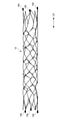
- FIG. 1 is a side view showing the configuration of the stent 10 of the first embodiment.
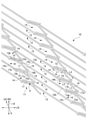
- FIG. 2 is a development view in which the stent 10 shown in FIG. 1 is virtually developed in a plane.
- FIG. 3 is a partially enlarged view of the stent 10 shown in FIG.
- FIG. 4A is a side view showing a state in which the diameter of the stent 10 shown in FIG. 1 is expanded.
- FIG. 4B is a side view of the stent 10 provided with the marker 100.
- FIG. 4C is a cross-sectional view of the marker 100.
- 5A-5C are views illustrating the protruding direction of the second apex 19 in the stent 10.
- the stent 10 has a substantially cylindrical shape.
- the peripheral wall of the stent 10 has a mesh pattern structure in which a plurality of cells having a congruent shape surrounded by a wire-like material are spread in the circumferential direction.
- FIG. 2 shows a state in which the stent 10 is expanded in a plane in order to facilitate understanding of the structure of the stent 10. Further, in FIG. 2, in order to show the periodicity of the mesh pattern, the mesh pattern is virtually repeated from the actual unfolded state.
- the "peripheral wall" of the stent 10 means a portion of the stent 10 having a substantially cylindrical structure that separates the inside and the outside of the cylinder.
- the "cell”, also referred to as an opening or compartment, refers to a portion surrounded by a wire-like material that forms the mesh pattern of the stent 10.
- the “strut” refers to each leg portion 15 to 17 made of the wire-shaped material, a connecting element 12 (described later), and the like.
- the material of the stent 10 a material having high rigidity of the material itself and high biocompatibility is preferable.
- Such materials include, for example, titanium, nickel, stainless steel, platinum, gold, silver, copper, iron, chromium, cobalt, aluminum, molybdenum, manganese, tantalum, tungsten, niobium, magnesium, calcium or alloys containing these.
- the stent 10 is particularly preferably made of a material having superelastic properties, such as a nickel titanium (Ni—Ti) alloy.
- the stent 10 shown in FIG. 1 can be manufactured by laser-machining a substantially cylindrical small-diameter tube made of the above material.
- a synthetic resin material such as polyolefin such as PE and PP, polyamide, polyvinyl chloride, polyphenylene sulfide, polycarbonate, polyether and polymethylmethacrylate can also be used.
- biodegradable resins biodegradable polymers
- PLA polylactic acid
- PHB polyhydroxybutyrate
- PGA polyglycolic acid
- poly ⁇ caprolactone poly ⁇ caprolactone
- the alloys include Ni—Ti alloy, Cu—Mn alloy, Cu—Cd alloy, Co—Cr alloy, Cu—Al—Mn alloy, Au—Cd—Ag alloy, Ti—Al—V alloy, magnesium and Zr, Y. , Ti, Ta, Nd, Nb, Zn, Ca, Al, Li, Mn and the like.
- a non-biodegradable resin can be used as the material of the stent 10.
- the stent 10 may be formed of any material as long as it has biocompatibility.
- the stent 10 may contain a drug.
- the term "stent 10 containing a drug” means that the stent 10 carries the drug so that the drug can be eluted.
- the agent is not limited, but for example, a physiologically active substance can be used.
- Physiologically active substances include agents that suppress intimal thickening, anticancer agents, immunosuppressants, antibiotics, antirheumatic agents, antithrombotic agents, HMG-CoA reductase inhibitors, ACE inhibitors, calcium antagonists, antihigh fats.
- Hypoglycemic agents anti-inflammatory agents, integrin inhibitors, antiallergic agents, antioxidants, GPIIbIIIa antagonists, retinoids, flavonoids and carotinoids, lipid improving agents, DNA synthesis inhibitors, tyrosine kinase inhibitors, antithrombotic agents, vascular smoothing Examples thereof include muscle growth inhibitor, antithrombotic drug, interferon and the like, and a plurality of these drugs can also be used.
- a drug that suppresses intima thickening that prevents restenosis is preferable, and as a drug that suppresses intima thickening, a drug having an intima thickening inhibitory action that does not inhibit the proliferation of endothelial cells can be mentioned.
- agents include, for example, Argatroban; (2R, 4R) -4-methyl-1- [N2-((RS) -3-methyl-1,2,3,4-tetrahydro-8-quinolinsulfonyl sulfonyl). ) -L-arginyl] -2-piperidincarboxylic acid (Japanese Patent Laid-Open No. 2001-190686; International Publication No.
- WO2007 / 058190 Ximelagatran, Melagatran, Dabigatran, Dabigatran etechyl (Dabigatran exilate), rapamycin, everolimus, biolimus A9, zotarolimus, tacrolimus, paclitaxel, statin and the like can be mentioned.
- the surface of the stent 10 may be covered with the drug.
- the surface of the stent 10 may be directly coated with a drug, or the drug may be contained in a polymer and the stent 10 may be coated with this polymer.
- the stent 10 may be provided with a groove or a hole for storing the drug as a reservoir, and the drug or a mixture of the drug and the polymer may be stored therein. Reservoirs for storage are described, for example, in JP-A-2009-542501.
- the polymers used in this case include silicone rubber, urethane rubber, fluororesin, polybutyl acrylate, polybutyl methacrylate, acrylic rubber, natural rubber, ethylene-vinyl acetate copolymer, styrene-butadiene block copolymer, and styrene-iso.
- Flexible polymers with a glass transition temperature (Tg) of -100 to 50 ° C such as Brenblock copolymers and styrene-isobutylene block copolymers, polylactic acid, poly (lactic acid-glycolic acid), polyglycolic acid, poly ( Examples thereof include biodegradable polymers such as lactic acid- ⁇ -caprolactone), poly (glycolic acid-trimethylene carbonate), and poly- ⁇ -hydroxybutyric acid.
- Tg glass transition temperature
- Brenblock copolymers and styrene-isobutylene block copolymers polylactic acid, poly (lactic acid-glycolic acid), polyglycolic acid, poly ( Examples thereof include biodegradable polymers such as lactic acid- ⁇ -caprolactone), poly (glycolic acid-trimethylene carbonate), and poly- ⁇ -hydroxybutyric acid.
- Mixing of the polymer with the drug can be performed, for example, by dispersing the drug in the polymer
- FIG. 1 shows a state in which a stent 10 in a state in which a tube having a diameter of 2 mm is laser-machined and then not stretched is virtually unfolded in a plane.
- FIG. 4A shows a state in which the stent 10 shown in FIG. 1 is expanded to a diameter of 5 mm. The stent 10 is radially reduced in diameter from the state shown in FIG.
- the stent 10 housed in the catheter is pushed out, the shape as shown in FIG. 4A is restored.
- an elastic material such as a superelastic alloy or a shape memory alloy
- the production of the stent 10 is not limited to laser processing, and can be produced by, for example, other methods such as cutting processing.
- markers 100 may be provided on both ends of the axial LD.
- FIG. 4B shows a configuration in which markers 100 are provided on both ends of the axial LD of the expanded stent 10 shown in FIG. 4A.
- the marker 100 is a member that serves as a marker for confirming the position of the stent 10 in a tubular organ such as a blood vessel, and is formed of a radiation-impermeable material.
- the marker 100 is composed of a tip portion 110 of the stent 10 and a coiled spring 120 provided on the outside of the tip portion 110. The tip of the tip 110 of the stent 10 projects from the coiled spring 120.
- the coiled spring 120 is preferably a material that is impermeable to radiation such as X-rays and can be molded into a coil shape.
- Examples of the material of the coiled spring 120 include a platinum-iridium (Pt-Ir) alloy.
- the joining method between the coiled spring 120 and the tip portion 110 of the stent 10 is not particularly limited as long as it is a joining method used for joining medical devices such as welding, UV bonding, and silver brazing infiltration.
- Welding methods include a method in which the coiled spring 120 and the tip portion 110 of the stent 10 are melted and fixed by welding, and a region in the tip portion 110 of the stent 10 that protrudes from the coiled spring 120 is melted. , A method of restricting the movement of the coiled spring 120, and the like.
- a medical grade radiation curable polymer is used to secure the coiled spring 120 to the tip 110 of the stent 10.
- the cured polymer of the liquid agent is applied to the tip 110 of the stent 10
- the coiled spring 120 is put on the tip portion 110, and then radiation is applied to them to promote the curing of the cured polymer of the liquid agent, and the coiled spring 120 is used. Is fixed to the tip 110 of the stent 10.
- the coiled spring 120 is formed of a material different from that of the stent 10, for example, silver brazing or the like is impregnated from above the coiled spring 120, and the coiled spring 120 is placed on the tip 110 of the stent 10. Fix it.
- the stent 10 of the first embodiment includes a plurality of annular bodies (wavy line pattern bodies) 11 arranged side by side in the axial direction (longitudinal axis direction, central axis direction) LD.
- a plurality of connecting elements 12 for connecting the annular bodies 11 adjacent to each other in the axial direction LD are provided.
- the annular CD of the annular body 11 is tilted with respect to the radial RD.
- the angle + ⁇ at which the annular direction CD of the annular body 11 is tilted with respect to the radial direction RD is, for example, 30 to 60 degrees.
- the annular body 11 has a wavy line pattern formed by a plurality of waveform units 14.
- the plurality of waveform units 14 are connected along the ring direction CD.
- the waveform unit 14 is composed of a first leg portion 15, a second leg portion 16, a third leg portion 17, a first top portion 18, and a second top portion 19.
- the first leg portion 15 is a leg portion arranged substantially parallel to the axial direction LD.
- the second leg portion 16 is a leg portion arranged substantially parallel to the ring direction CD.
- the annular CD of the annular body 11 is tilted by an angle + ⁇ with respect to the radial RD.
- the total length of the length L1 of the first leg portion 15 of the waveform unit 14 and the length L2 of the second leg portion 16 is ,
- the length of the third leg 17 is longer than the length L3.
- one first end portion 15a of the first leg portion 15 and one first end portion 16a of the second leg portion 16 are connected by a first top portion 18.
- the other second end portion 16b of the second leg portion 16 and the one first end portion 17a of the third leg portion 17 are connected by a second top portion 19.
- the other second end 17b of the third leg 17 is connected to the other second end 15b of the first leg 15 of the waveform unit 14 adjacent to the ring direction CD (around the axis).
- the second top portion 19 connecting the second leg portion 16 and the third leg portion 17 is not connected to any of the waveform units 14 adjacent to the ring-direction CD.
- the third leg portion 17 of the waveform unit 14 and the first leg portion 15 of the waveform unit 14 adjacent to each other around the axis line have their respective ends (second end) so that a slit S is formed between them. It is connected to the portion 17b at the second end portion 15b).
- the stent 10 of the first embodiment has two waveform units 14 adjacent to each other in the axial LD and two connecting elements 12 (described later) connecting these two waveform units 14 in the axial LD. The cell is formed by.
- This cell basically has a closed cell structure, but in each waveform unit 14, the second top 19 is a substantially V-shaped free end. Therefore, the stent 10 of the first embodiment is formed so that a part of the closed cell structure locally becomes an open cell structure. As will be described later, when the diameter of the stent 10 is expanded, the second leg portion 16 and the third leg portion 17 are deformed in a direction away from each other with the second top portion 19, which is a free end, as the center.
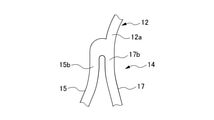
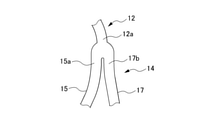
- the plurality of connecting elements 12 are arranged at equal intervals along the annular direction CD of the annular body 11. Each connecting element 12 extends spirally around the central axis. As shown in FIG. 3, one first end portion 12a of the connecting element 12 is connected to the first top portion 18 of one of the adjacent waveform units 14 in the axial direction LD. That is, the first end portion 12a of the connecting element 12 is attached to the first end portion 15a of the first leg portion 15 and the first end portion 16a of the second leg portion 16 in the first top portion 18 of the waveform unit 14a. It is connected.
- the other second end portion 12b of the connecting element 12 is adjacent to the second end portion 17b of the third leg portion 17 of the other waveform unit 14b adjacent to the axial LD, and to the waveform unit 14b around the axis. It is connected to the second end portion 15b of the first leg portion 15 of the waveform unit 14c.
- some waveform units 14 are designated by the reference numerals “14a”, “14b”, and “14c”.
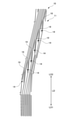
- FIG. 5A is a diagram showing the entire stent 10 virtually expanded in a plane.
- the side closer to the practitioner in the axial LD of the stent 10 is the proximal side LD1, and the side away from the practitioner. Is designated as the distal LD2.
- the annular body 11 and the connecting element 12 are simplified and drawn.
- the stent 10 is placed in a tubular organ such as a blood vessel, but in some cases, it may be re-placed in another place. In that case, the stent 10 is temporarily recontained in the catheter.
- the direction in which the stent 10 is re-stored is the direction from the distal LD2 to the proximal LD1.
- FIG. 5B is an enlarged view from the center of the axial LD of the stent 10 to the end of the proximal LD1.
- FIG. 5C is an enlarged view from the center of the axial LD of the stent 10 to the end of the LD2 on the distal side.
- the second apex 19 is distal in the direction of insertion of the stent 10 into the catheter (LD2 to LD1). It is formed so as to protrude from LD2. According to the above configuration, when the stent 10 is re-stored in the catheter, the substantially V-shaped tip of the second apex 19 which is the free end does not face the insertion port of the catheter, so that the stent 10 can be easily re-stored in the catheter. can do.
- FIG. 6 is a diagram showing the shape of each part when the expanded stent 10 (see FIG. 4A) is bent into a substantially U shape.
- FIG. 7 is a schematic view of the state of the cell 40 in each region of the stent 10 shown in FIG. 6 when the state of the cell 40 is virtually expanded in a plane.
- the middle figure of FIG. 7 shows the cell 40 in a no-load state (state of FIG. 4A) in which neither pulling force nor compression force is applied.
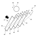
- FIG. 8 is a schematic view of the state of the continuous cells 40 in the region S1 of the bent stent 10 shown in FIG. 6 when the state of the continuous cells 40 is virtually expanded in a plane.
- the cross section of the strut 50 is schematically drawn as a circle in the upper row. This circle is drawn to explain the stress acting on one strut 50 and is different from the actual cross section of the strut.
- the cell 40 is in a pulled state in the region S1 on the dorsal side (outside) of the bent portion.
- the stress acting on the region S1 is in the direction of the arrows 51 and 52 at the connection point a of each strut 50 constituting the cell 40, as shown in the upper part of FIG. Therefore, as shown in FIG. 8, the continuous cells 40 in the region S1 are deformed so as to be stretched in the direction of the arrow 53. That is, in FIG. 8, the strut 50 of the cell 40 in the unloaded state shown by the dotted line is deformed (moved) so as to be stretched in the direction of the arrow 53 as shown by the solid line.
- the strut 50 when the strut 50 is viewed from the cross-sectional direction, as shown in the upper part of FIG. 8, the strut 50 is deformed so as to rotate in two directions as shown by the arrow 54.
- the direction indicated by the arrow 54 shown in the upper part of FIG. 8 corresponds to the direction of the arrow 53 shown in the lower part of FIG.
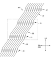
- FIG. 9 is a development view in which the stent 20 of Comparative Example 1 is virtually developed in a plane.
- FIG. 10 is a partially enlarged view of the stent 20 shown in FIG.
- FIG. 11 is a schematic view of the state of the continuous cells 40 in the dorsal region of the bent stent 20 when the state of the continuous cells 40 is virtually expanded in a plane.
- FIG. 11 is a schematic view of a case where the state of continuous cells 40 in the dorsal region of the stent 20 of Comparative Example 1 that has been bent is virtually expanded in a plane.
- the stent 20 of Comparative Example 1 includes a plurality of annular bodies 21 arranged side by side in the axial direction LD, and a connecting element 22 connecting the annular bodies 21 adjacent to the axial direction LD. ing.
- the annular CD of the annular body 21 substantially coincides with the radial RD.
- the stent 20 of Comparative Example 1 has a wavy line pattern formed by connecting a plurality of substantially V-shaped V-shaped elements 23 in the circumferential direction.
- the V-shaped element 23 is formed by connecting two legs 24 at a top 25.
- the top portion 25 faces in the same direction in the axial direction LD, and the wavy line pattern is formed by connecting the leg portions 24 of the adjacent V-shaped elements 23 in the circumferential direction. ..
- each connection element 22 connect two adjacent V-shaped elements 23 in the axial direction LD, respectively.
- One end 22a of the connecting element 22 is a V-shaped element 23 adjacent to the axial LD, and is connected to each leg 24 of the two adjacent V-shaped elements 23 along a wavy pattern. ..
- the other end portion 22b of the connecting element 22 is connected to the top portion 25 of the V-shaped element 23 adjacent to the axial LD.
- all the tops 25 are connected to the connecting element 22. Therefore, the stent 20 of Comparative Example 1 has a closed cell structure without a free end.
- the cell 40 When the stent 20 of Comparative Example 1 is expanded in diameter in the same manner as the stent 10 of the embodiment (see FIG. 4) and bent into a substantially U shape, the cell 40 is in a pulled state in the dorsal region. At this time, the continuous cells 40 in the dorsal region are deformed diagonally in the direction of the arrow 55, as shown in FIG. That is, in FIG. 11, the strut 50 of the cell 40 in the no-load state shown by the dotted line is deformed (moved) as shown by the solid line. At this time, when the strut 50 is viewed from the cross-sectional direction, as shown in the upper part of FIG. 11, the strut 50 is deformed so as to rotate in one direction of the arrow 56.
- the direction indicated by the arrow 56 shown in the upper part of FIG. 11 corresponds to the direction of the arrow 55 shown in the lower part of FIG.
- the deformation of the cell 40 is small in the dorsal region of the bent portion, and the deformation of the strut 50 is only one direction when viewed from the cross-sectional direction. .. Therefore, in the stent 20 of Comparative Example 1, the amount of deformation for absorbing the stress acting on the dorsal region is smaller than that of the stent 10 of the embodiment. That is, in the stent 20 of Comparative Example 1, the stress acting on the bent portion tends to cause crushing in the dorsal region. The same applies to the ventral region of the bent portion in the stent 20 of Comparative Example 1, and the structure is such that crushing is likely to occur due to the stress acting on the bent portion.
- FIG. 12 is a development view in which the stent 30 of Comparative Example 2 is virtually developed in a plane.
- FIG. 13 is a partially enlarged view of the stent 30 shown in FIG.
- FIG. 14 is a schematic view of the state of continuous cells 40 in the dorsal region of the bent stent 30 when the state of the continuous cells 40 is virtually expanded in a plane.
- the stent 30 of Comparative Example 2 includes a plurality of annular bodies 31 arranged side by side in the axial direction LD, and a connecting element 32 connecting the annular bodies 31 adjacent to the axial direction LD. ing.
- the annular CD of the annular body 31 is inclined with respect to the radial RD.
- the stent 30 of Comparative Example 2 has a wavy pattern formed by connecting a plurality of substantially V-shaped V-shaped elements 33 to a ring-direction CD.
- the V-shaped element 33 is formed by connecting two legs 34 at a top 35.
- the top portion 35 faces in the same direction in the axial direction LD, and the leg portions 34 of the adjacent V-shaped elements 33 are connected to each other in the ring direction CD to form a wavy pattern.
- each connection element 32 connect two adjacent V-shaped elements 33 in the axial direction LD, respectively.
- One end 32a of the connecting element 32 is a V-shaped element 33 adjacent to the axial LD, and each leg of two adjacent V-shaped elements 33 along a wavy pattern extending along the annular CD. It is connected to the unit 34.
- the other end portion 32b of the connecting element 32 is connected to the top portion 35 of the V-shaped element 33 adjacent to the axial LD.
- all the tops 35 are connected to the connecting element 32. Therefore, the stent 30 of Comparative Example 2 has a closed cell structure without a free end.
- the cell When the stent 30 of Comparative Example 2 is expanded in diameter in the same manner as the stent 10 of the embodiment (see FIG. 4A) and bent into a substantially U shape, the cell is in a pulled state in the dorsal region. At this time, the continuous cells in the dorsal region are deformed diagonally in the direction of the arrow 57, as shown in FIG. That is, in FIG. 14, the strut 50 of the cell in the unloaded state shown by the dotted line is deformed (moved) as shown by the solid line. At this time, when the strut 50 is viewed from the cross-sectional direction, as shown in the upper part of FIG. 14, the strut 50 is deformed so as to rotate in one direction of the arrow 58.
- the direction of the arrow 58 shown in the upper part of FIG. 14 corresponds to the direction of the arrow 57 shown in the lower part of FIG.
- the amount of deformation for absorbing the stress acting on the dorsal region is smaller than that of the stent 10 of the embodiment. That is, in the stent 30 of Comparative Example 2, crushing is likely to occur in the dorsal region due to the stress acting on the bent portion. The same applies to the ventral region of the bent portion in the stent 30 of Comparative Example 2, and the structure is such that crushing is likely to occur due to the stress acting on the bent portion.
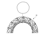
- 15A to 15C are diagrams illustrating the patency of each stent of Comparative Example 1, Comparative Example 2, and the embodiment, respectively.
- 15A to 15C show the cross-sectional shapes of the stents of Comparative Example 1, Comparative Example 2 and the embodiment when they are expanded to the same diameter and bent into a substantially U shape.
- the upper part of FIGS. 15A to 15C shows the cross-sectional shape at the central portion of the bend shown by the broken line.
- the lower part of FIGS. 15A to 15C shows the appearance when the stent is bent into a substantially U shape.
- Both the stent 20 of Comparative Example 1 shown in FIG. 15A and the stent 30 of Comparative Example 2 shown in FIG. 15B have kinks whose cross sections are crushed into a substantially elliptical shape, and their patency to bending is low. It became clear. It is considered that this is because in the stent 20 of Comparative Example 1 and the stent 30 of Comparative Example 2, each cell is deformed only in one direction due to the stress due to bending. On the other hand, it was revealed that the stent 10 of the embodiment shown in FIG. 15C has less crushing of the cross section and has high patency for bending. It is considered that this is because in the stent 10 of the embodiment, each cell is deformed in two directions in response to the stress due to bending.
- the stent 10 of the first embodiment has a free end (second apex 19) at a plurality of corrugated units 14 forming a wavy pattern, it is free when the stent 10 is bent.
- the two legs connected to the ends can move away from each other, deforming the entire cell in two directions. Therefore, the stent 10 of the embodiment has high patency to bending.
- the stent 10 of the first embodiment is formed so that the second apex 19 which is a free end protrudes distally in the insertion direction into the catheter. According to this configuration, when the stent 10 is re-stored in the catheter, the substantially V-shaped tip of the second apex 19, which is the free end, does not face the insertion port of the catheter, so that the stent 10 can be easily re-installed in the catheter. Can be stored.
- the third leg portion 17 of the waveform unit 14 and the first leg portion 15 of the waveform unit 14 adjacent to each other around the axis are end portions so that a slit S is formed between them. They are connected to each other. Therefore, in the stent 10 of the first embodiment, the third leg portion 17 connected to the first leg portion 15 and the second leg portion 16 connected to the third leg portion 17 and the second top portion 19 are provided. It can be deformed more greatly.
- FIG. 16 is a developed view of the stent 10A of the second embodiment virtually developed in a plane.
- FIG. 17 is a developed view showing a state in which the diameter of the stent 10A is reduced.
- FIG. 18 is a diagram showing a shape when the expanded stent 10A is bent into a substantially U shape.
- the length L4 of the connecting element 12 is set shorter than the length L2 of the second leg portion 16.
- the length L4 of the connecting element 12 is set to be, for example, about 0.7 to 0.9 in the value of L4 / L2.
- the length L4 of the connecting element 12 and the length L2 of the second leg portion 16 are measured at the shortest distance (straight line distance).
- the plurality of waveform units 14 are connected along the radial RD. That is, when the stent 10A of the second embodiment is viewed in the radial RD perpendicular to the axial LD, the annular CD of the annular body 11 substantially coincides with the radial RD.
- the length L4 of the connecting element 12 is set shorter than the length L2 of the second leg portion 16. According to this configuration, since the distance between adjacent waveform units 14 in the axial LD is shortened, the number of waveform units 14 per unit length of the axial LD can be increased. As described above, as the number of waveform units 14 increases, the surface area per unit length of the axial LD increases, so that the blood vessel retention performance of the stent 10A can be further improved.
- the plurality of waveform units 14 are connected along the radial RD. Therefore, during the processing of the stent, the stress acting in the strut is uniformly transmitted to the radial RD in the step of expanding the diameter of the laser-processed small-diameter tube to the finished diameter. In this way, when the stress acting in the strut is uniformly transmitted in the radial direction, twisting of the strut due to local non-uniformity of stress is less likely to occur, so that the strut expands more evenly in the circumferential direction. The shape can be obtained. Further, in the stent 10A of the second embodiment, since a plurality of waveform units 14 can be patterned along the radial RD, the workability is also excellent.
- the basic structure of the waveform unit 14 is the same as that of the first embodiment. That is, as shown in FIG. 17, in the waveform unit 14, the substantially V-shaped tip of the second apex 19 is distal in the insertion direction (LD2 to LD1) of the stent 10A into the catheter (not shown). It is formed so as to protrude from LD2. Therefore, the stent 10A of the second embodiment can be easily re-stored in the catheter as in the first embodiment. Further, as shown in FIG. 17, in the stent 10A of the second embodiment, since the second top portion 19 does not easily overlap with the connecting element 12 in the reduced diameter state, the stent 10A can be deployed more evenly when the diameter is expanded. can.
- the two legs 16 and 17 connected to the second top 19 which becomes the free end when the stent is bent in a substantially U shape are attached to each other. It has a high patency to bending because it can move away and deform the entire cell in two directions.
- the present disclosure is not limited to the above-described embodiment, and various deformations and changes are possible as in the deformation form described later. Is also included within the technical scope of this disclosure. Moreover, the effects described in the embodiments are merely a list of the most suitable effects resulting from the present disclosure, and are not limited to those described in the embodiments. The above-described embodiment and the modified form described later may be used in combination as appropriate, but detailed description thereof will be omitted.
- FIG. 19 is a developed view of the stent 10B in the first modified form, which is virtually developed in a plane.
- the stent 10B of the first modification is different from the stent 10 of the first embodiment in the direction in which the annular CD of the annular body 11 is inclined with respect to the radial RD.
- the annular CD of the annular body 11 has an angle ⁇ with respect to the radial RD. It is tilted. As shown in FIG.
- the length L1 of the first leg portion 15 and the length of the second leg portion 16 of the waveform unit 14 is shorter than the length L3 of the third leg portion 17.
- the direction in which the annular CD of the annular body 11 is inclined with respect to the radial RD may be opposite to that of the stent 10 of the first embodiment (see FIG. 2). Also in this configuration, the same effect as that of the stent 10 of the first embodiment can be obtained.
- the configuration of the first modification can also be applied to the stent 10A of the second embodiment.
- 20A to 20C are partially enlarged views of the waveform unit 14 of the second modified form.
- a connection shape as shown in FIGS. 20A to 20C can be applied to the connection portion between the connection element 12 and the waveform unit 14.
- 20A to 20C show a shape applicable to the connection portion of any of the regions A1 or A2 of the waveform unit 14 shown in FIG.
- the connection portion shown in the area A1 of FIG. 2 will be described as an example.
- the region A1 is a portion where the first end portion 12a of the connecting element 12 and the second end portion 15b of the first leg portion 15 of the waveform unit 14 and the second end portion 17b of the third leg portion 17 are connected. ..
- connection shape shown in FIG. 20A the first end portion 12a of the connection element 12 is connected to the side of the second end portion 17b of the third leg portion 17.
- first end portion 12a of the connection element 12 is connected to the side of the second end portion 15b of the first leg portion 15.
- connection shape shown in FIG. 20C the first end portion 12a of the connection element 12 is connected between the second end portion 15b of the first leg portion 15 and the second end portion 17b of the third leg portion 17. .
- the connection shape shown in each figure of the second modified form can be appropriately selected depending on, for example, the transmission of force when the stent is bent, and the state of stress acting on the inside and the surface.
- FIG. 21 and 22 are development views of the stent 10C in the third modified form, which is virtually developed in a plane.
- FIG. 21 is a developed view showing the first configuration of the stent 10C in the third modified form.
- the connecting element 12 connecting the annular bodies 11 adjacent to the axial LD is formed so as to have a substantially S-shaped wavy pattern.
- FIG. 22 is a developed view showing a second configuration of the stent 10C in the third modified form. As shown in FIG.
- the connecting element 12 connecting the annular bodies 11 adjacent to each other in the axial direction LD has a substantially S-shaped wavy pattern twice in succession. It is formed like this.
- the substantially S-shaped wavy line pattern may be continuous three times or more.
- the shape of the connecting element 12 shown in each of the third modified forms can be appropriately selected depending on, for example, the transmission of force when the stent is bent, and the state of stress acting on the inside and the surface.
- FIG. 23 is a developed view of the stent 10D in the fourth modified form, which is virtually developed in a plane.
- the connecting element 12 connecting the first leg portion 15, the second leg portion 16 and the third leg portion 17 constituting the waveform unit 14 and the annular bodies 11 to each other has a strut thickness (for example,). , Maximum diameter) may be different.
- the thickness of the connecting element 12 is reduced with respect to the thickness of the first leg portion 15, the second leg portion 16, and the third leg portion 17. Shows.
- the thickness of the struts in the first leg 15, the second leg 16, the third leg 17, and the connecting element 12 depends on the force transmission when the stent is flexed and the state of stress acting on the inside and the surface. Can be selected as appropriate.
- an example of thinning the connecting element 12 was shown, but the thickness of the strut is changed by changing the thickness of the first leg portion 15, the second leg portion 16, and the third leg portion. 17 and any one or more of the connecting elements 12 may be used.
- FIG. 24 is a developed view of the stent 10E in the fifth modified form, which is virtually developed in a plane.
- the stent 10E in the fifth modified form is provided with two connection element bands L12 between two connection points (x) in the radial RD.
- the two connection points (x) indicate virtual connection positions of the substantially cylindrical stent 10D in the circumferential direction.
- the connection element band L12 shows a row of a plurality of connection elements 12 arranged along the ring direction CD.
- two connecting element bands L12 are provided between the two connecting points (x) in the radial direction.
- the stent 10E in the fifth modified form is a stent as compared with a configuration in which one connection element band L12 is provided between two connection points (x) in the radial direction (see, for example, FIG. 2). Surface area and cell density can be increased. In the stent 10E shown in FIG. 24, three or more connection element bands L12 may be provided between the two connection points (x) in the radial direction.
- FIG. 25 is a development view in which the stent 10F of the sixth deformed form is virtually developed in a plane.
- FIG. 25 shows the range from approximately the center of the axial LD of the stent 10F to the end of the proximal LD1.
- the stent 10F is provided with a marker holding portion 13 at the end of the proximal LD1.
- the marker holding portion 13 is a portion that holds the marker 130 (described later).
- FIG. 25 shows an example in which three marker holding portions 13 are provided at the end of the LD1 on the proximal side of the stent 10F, but the number of marker holding portions 13 is not limited to the example of FIG. 25.
- the marker holding portion 13 has a slit 13a formed along the central portion in the longitudinal direction.
- the slit 13a is a portion to be fastened to a substantially central portion of the marker 130 by caulking.
- the marker holding portion 13 at the left end shows a state before the marker 130 is fastened.
- the marker 130 used for the sixth modified form of the stent 10F is formed in a substantially cylindrical shape.
- a substantially semicircular head 131 is formed at one end, and an opening 132 is formed at the other end.
- the head 131 is located in the insertion direction (LD2 to LD1) when the stent 10F is re-stored into a catheter (not shown).
- the marker 130 is made of a radiation opaque material, like the marker 100 described in the first embodiment (see FIG. 4B).
- the marker 130 can be fastened to the marker holding portion 13 of the stent 10F by inserting the marker 130 into the marker holding portion 13 of the stent 10F from the opening 132 side and caulking the marker 130. ..
- the range from approximately the center of the axial LD of the stent 10F to the end of the distal LD2 is configured in the same manner as in FIG. 25.
- the substantially semicircular head 131 is located on the side in the insertion direction of the marker 130, so that the stent 10F is placed in the catheter. Can be easily re-stored.
Landscapes
- Health & Medical Sciences (AREA)
- Engineering & Computer Science (AREA)
- Biomedical Technology (AREA)
- Heart & Thoracic Surgery (AREA)
- Cardiology (AREA)
- Oral & Maxillofacial Surgery (AREA)
- Transplantation (AREA)
- Vascular Medicine (AREA)
- Life Sciences & Earth Sciences (AREA)
- Animal Behavior & Ethology (AREA)
- General Health & Medical Sciences (AREA)
- Public Health (AREA)
- Veterinary Medicine (AREA)
- Optics & Photonics (AREA)
- Physics & Mathematics (AREA)
- Media Introduction/Drainage Providing Device (AREA)
Abstract
Description
このような課題を解決するために、クローズドセル構造のステントでありながら高い柔軟性を発揮する技術として、螺旋状のステントが提案されている(例えば、特許文献1参照)。特許文献1のステントは、展開状態において、波線状パターンを有する螺旋状の環状体と、隣り合う環状体を接続するコイル状要素とを備える。
本明細書等において、形状、幾何学的条件、これらの程度を特定する用語、例えば、「平行」、「方向」等の用語については、その用語の厳密な意味に加えて、ほぼ平行とみなせる程度の範囲、概ねその方向とみなせる範囲を含む。
図1は、第1実施形態のステント10の構成を示す側面図である。図2は、図1に示すステント10を仮想的に平面状に展開した展開図である。図3は、図2に示すステント10の部分拡大図である。図4Aは、図1に示すステント10を拡径した状態を示す側面図である。図4Bは、マーカー100を設けたステント10の側面図である。図4Cは、マーカー100の断面図である。図5A~図5Cは、ステント10における第2頂部19の突出方向を説明する図である。
また、ステント10の表面を、ダイヤモンドライクカーボン(DLC,F-DLC)等の炭素系材料により被覆してもよい。
溶接の方法としては、コイル状バネ120とステント10の先端部110とを溶接で溶かし込んで接着固定する方法と、ステント10の先端部110において、コイル状バネ120から突出している領域を溶かして、コイル状バネ120の移動を規制する方法と、が挙げられる。
銀ロウの浸潤の場合、コイル状バネ120をステント10とは異なる材料から形成し、例えば銀ロウ等をコイル状バネ120の上から染み込ませて、コイル状バネ120をステント10の先端部110に固定する。
図6は、拡径したステント10(図4A参照)を略U字形に屈曲させた場合の各部の形状を示す図である。図7は、図6に示すステント10の各領域におけるセル40の状態を仮想的に平面状に展開した場合の模式図である。図7の中段の図は、引っ張り、圧縮のいずれの力も作用していない無負荷状態(図4Aの状態)のセル40を示している。図8は、図6に示す屈曲させたステント10の領域S1における連続したセル40の状態を仮想的に平面状に展開した場合の模式図である。図8では、上段にストラット50の断面を模式的に円で描いている。この円は、一つのストラット50に作用する応力を説明するために描いたものであり、実際のストラットの断面とは異なる。
図9は、比較例1のステント20を仮想的に平面状に展開した展開図である。図10は、図9に示すステント20の部分拡大図である。図11は、屈曲させたステント20の背側の領域における連続したセル40の状態を仮想的に平面状に展開した場合の模式図である。図11は、屈曲させた比較例1のステント20の背側の領域における連続したセル40の状態を仮想的に平面状に展開した場合の模式図である。
図15A~図15Cは、それぞれ比較例1、比較例2及び実施形態の各ステントの開存性を説明する図である。図15A~図15Cは、比較例1、比較例2及び実施形態のそれぞれのステントを同一の径となるまで拡径し、略U字形に屈曲させたときの断面形状を示している。図15A~図15Cの上段は、破線で示す曲がりの中心部分での断面形状を示している。図15A~図15Cの下段は、ステントを略U字形に屈曲させたときの外観を示している。
次に、第2実施形態のステント10Aについて説明する。第2実施形態の説明及び図面において、第1実施形態と同等の部材等には、第1実施形態と同一の符号を付し、重複する説明を省略する。
11 環状体(波線状パターン体)
12 接続要素
12a 第1端部
12b 第2端部
14 波形単位
15 第1脚部
15a 第1端部
15b 第2端部
16 第2脚部
16a 第1端部
16b 第2端部
17 第3脚部
17a 第1端部
17b 第2端部
18 第1頂部
19 第2頂部
100 マーカー
Claims (7)
- 波線状パターンを有し且つ軸線方向に並んで配置される複数の波線状パターン体と、軸線周りに配置され且つ隣り合う前記波線状パターン体を接続する複数の接続要素と、を備え、縮径された状態でカテーテルに挿入されるステントであって、
前記波線状パターンは、第1脚部、第2脚部及び第3脚部と、前記第1脚部の一方の第1端部と前記第2脚部の一方の第1端部とを連結する第1頂部と、前記第2脚部の他方の第2端部と前記第3脚部の一方の第1端部とを連結する第2頂部とを備える複数の波形単位により形成され、前記第3脚部の他方の第2端部は、軸線周りに隣り合う前記波形単位の前記第1脚部の他方の第2端部と接続されており、
前記接続要素の一方の第1端部は、軸線方向において隣り合う一方の前記波形単位の前記第1頂部に接続され、前記接続要素の他方の第2端部は、軸線方向に隣り合う他方の前記波形単位の前記第1脚部の前記第2端部と接続される、
ステント。 - 前記波形単位の前記第2頂部は、前記ステントのカテーテルへの挿入方向において遠位側に突出するように形成される、
請求項1に記載のステント。 - 前記第3脚部と、軸線周りに隣り合う前記波形単位の前記第1脚部とは、その間にスリットが形成されるように、それぞれの端部同士において連結されている、
請求項1又は2に記載のステント。 - 軸線方向に対して垂直な径方向から視たときに、前記波線状パターン体の前記波線状パターンの環方向は、前記径方向に対して傾斜している、
請求項1~3までのいずれか一項に記載のステント。 - 前記第1脚部の長さと前記第2脚部の長さとを足した長さは、前記第3脚部の長さよりも長い、
請求項4に記載のステント。 - 前記第1脚部の長さと前記第2脚部の長さとを足した長さは、前記第3脚部の長さよりも短い、
請求項4に記載のステント。 - 前記接続要素の長さは、前記第2脚部の長さよりも短く、
軸線方向に対して垂直な径方向から視たときに、前記波線状パターン体の前記波線状パターンの環方向は、前記径方向と略一致している、
請求項1~3までのいずれか一項に記載のステント。
Priority Applications (12)
| Application Number | Priority Date | Filing Date | Title |
|---|---|---|---|
| CN202310308468.6A CN116785038A (zh) | 2020-08-12 | 2021-08-11 | 支架 |
| EP21855984.7A EP4014933A4 (en) | 2020-08-12 | 2021-08-11 | STENTS |
| CN202180005258.9A CN114364351B (zh) | 2020-08-12 | 2021-08-11 | 支架 |
| JP2021571402A JP7029578B1 (ja) | 2020-08-12 | 2021-08-11 | ステント |
| NZ786736A NZ786736A (en) | 2020-08-12 | 2021-08-11 | Stent |
| BR112022004391A BR112022004391A2 (pt) | 2020-08-12 | 2021-08-11 | Stent |
| KR1020227008704A KR102558760B1 (ko) | 2020-08-12 | 2021-08-11 | 스텐트 |
| MX2022003630A MX2022003630A (es) | 2020-08-12 | 2021-08-11 | Stent. |
| US17/753,584 US11590009B2 (en) | 2020-08-12 | 2021-08-11 | Stent |
| AU2021326319A AU2021326319B2 (en) | 2020-08-12 | 2021-08-11 | Stent |
| CA3154198A CA3154198C (en) | 2020-08-12 | 2021-08-11 | Stent |
| US18/163,223 US20230181341A1 (en) | 2020-08-12 | 2023-02-01 | Stent |
Applications Claiming Priority (2)
| Application Number | Priority Date | Filing Date | Title |
|---|---|---|---|
| JP2020-136261 | 2020-08-12 | ||
| JP2020136261 | 2020-08-12 |
Related Child Applications (2)
| Application Number | Title | Priority Date | Filing Date |
|---|---|---|---|
| US17/753,584 A-371-Of-International US11590009B2 (en) | 2020-08-12 | 2021-08-11 | Stent |
| US18/163,223 Continuation US20230181341A1 (en) | 2020-08-12 | 2023-02-01 | Stent |
Publications (1)
| Publication Number | Publication Date |
|---|---|
| WO2022034905A1 true WO2022034905A1 (ja) | 2022-02-17 |
Family
ID=80248007
Family Applications (1)
| Application Number | Title | Priority Date | Filing Date |
|---|---|---|---|
| PCT/JP2021/029676 Ceased WO2022034905A1 (ja) | 2020-08-12 | 2021-08-11 | ステント |
Country Status (11)
| Country | Link |
|---|---|
| US (2) | US11590009B2 (ja) |
| EP (1) | EP4014933A4 (ja) |
| JP (1) | JP7029578B1 (ja) |
| KR (1) | KR102558760B1 (ja) |
| CN (2) | CN116785038A (ja) |
| AU (1) | AU2021326319B2 (ja) |
| BR (1) | BR112022004391A2 (ja) |
| CA (1) | CA3154198C (ja) |
| MX (1) | MX2022003630A (ja) |
| NZ (1) | NZ786736A (ja) |
| WO (1) | WO2022034905A1 (ja) |
Cited By (2)
| Publication number | Priority date | Publication date | Assignee | Title |
|---|---|---|---|---|
| WO2024080365A1 (ja) * | 2022-10-14 | 2024-04-18 | 株式会社Bolt Medical | 遠位スタビライザ |
| WO2026063469A1 (ja) * | 2024-09-18 | 2026-03-26 | 株式会社ウィルビーボート | ステント |
Families Citing this family (1)
| Publication number | Priority date | Publication date | Assignee | Title |
|---|---|---|---|---|
| CN118000984B (zh) * | 2024-01-30 | 2025-01-07 | 巴特勒生物科技(苏州)有限公司 | 一种闭环支架 |
Citations (7)
| Publication number | Priority date | Publication date | Assignee | Title |
|---|---|---|---|---|
| JP2001190687A (ja) | 2000-01-07 | 2001-07-17 | Kawasumi Lab Inc | ステント及びステントグラフト |
| WO2007058190A1 (ja) | 2005-11-16 | 2007-05-24 | Tokai University Educational System | 薬剤放出制御組成物および薬剤放出性医療器具 |
| US20090024205A1 (en) * | 2007-07-19 | 2009-01-22 | Bay Street Medical | Radially Expandable Stent |
| WO2009031295A1 (ja) | 2007-09-04 | 2009-03-12 | Japan Stent Technology Co., Ltd. | 薬剤徐放性ステント |
| JP2013517913A (ja) * | 2010-01-30 | 2013-05-20 | アボット カーディオヴァスキュラー システムズ インコーポレイテッド | 圧縮復元可能な高分子スキャフォールド |
| WO2015125320A1 (ja) * | 2014-02-19 | 2015-08-27 | 株式会社World Medish | 高柔軟性ステント |
| WO2015145596A1 (ja) * | 2014-03-25 | 2015-10-01 | 株式会社World Medish Technology | 柔軟性ステント |
Family Cites Families (10)
| Publication number | Priority date | Publication date | Assignee | Title |
|---|---|---|---|---|
| US6783543B2 (en) * | 2000-06-05 | 2004-08-31 | Scimed Life Systems, Inc. | Intravascular stent with increasing coating retaining capacity |
| US5948016A (en) * | 1997-09-25 | 1999-09-07 | Jang; G. David | Intravascular stent with non-parallel slots |
| JP2004267492A (ja) * | 2003-03-10 | 2004-09-30 | Nipro Corp | 血管径保持性の優れた柔軟なステント |
| JP4928891B2 (ja) * | 2006-09-29 | 2012-05-09 | テルモ株式会社 | 自己拡張型生体内留置用ステント |
| US7988723B2 (en) | 2007-08-02 | 2011-08-02 | Flexible Stenting Solutions, Inc. | Flexible stent |
| US9345602B2 (en) | 2010-09-23 | 2016-05-24 | Abbott Cardiovascular Systems Inc. | Processes for making crush recoverable polymer scaffolds |
| CN202740162U (zh) * | 2012-02-27 | 2013-02-20 | 江苏省华星医疗器械实业有限公司 | 新型血管支架 |
| JP2017164323A (ja) * | 2016-03-16 | 2017-09-21 | テルモ株式会社 | ステント |
| JP2018046934A (ja) * | 2016-09-20 | 2018-03-29 | テルモ株式会社 | ステント |
| KR102450174B1 (ko) * | 2016-10-04 | 2022-10-05 | 야스히로 쇼바야시 | 유연성 스텐트 |
-
2021
- 2021-08-11 JP JP2021571402A patent/JP7029578B1/ja not_active Expired - Fee Related
- 2021-08-11 CN CN202310308468.6A patent/CN116785038A/zh active Pending
- 2021-08-11 CA CA3154198A patent/CA3154198C/en active Active
- 2021-08-11 US US17/753,584 patent/US11590009B2/en active Active
- 2021-08-11 KR KR1020227008704A patent/KR102558760B1/ko active Active
- 2021-08-11 CN CN202180005258.9A patent/CN114364351B/zh not_active Expired - Fee Related
- 2021-08-11 WO PCT/JP2021/029676 patent/WO2022034905A1/ja not_active Ceased
- 2021-08-11 AU AU2021326319A patent/AU2021326319B2/en not_active Ceased
- 2021-08-11 EP EP21855984.7A patent/EP4014933A4/en not_active Withdrawn
- 2021-08-11 NZ NZ786736A patent/NZ786736A/en not_active IP Right Cessation
- 2021-08-11 BR BR112022004391A patent/BR112022004391A2/pt not_active Application Discontinuation
- 2021-08-11 MX MX2022003630A patent/MX2022003630A/es unknown
-
2023
- 2023-02-01 US US18/163,223 patent/US20230181341A1/en not_active Abandoned
Patent Citations (7)
| Publication number | Priority date | Publication date | Assignee | Title |
|---|---|---|---|---|
| JP2001190687A (ja) | 2000-01-07 | 2001-07-17 | Kawasumi Lab Inc | ステント及びステントグラフト |
| WO2007058190A1 (ja) | 2005-11-16 | 2007-05-24 | Tokai University Educational System | 薬剤放出制御組成物および薬剤放出性医療器具 |
| US20090024205A1 (en) * | 2007-07-19 | 2009-01-22 | Bay Street Medical | Radially Expandable Stent |
| WO2009031295A1 (ja) | 2007-09-04 | 2009-03-12 | Japan Stent Technology Co., Ltd. | 薬剤徐放性ステント |
| JP2013517913A (ja) * | 2010-01-30 | 2013-05-20 | アボット カーディオヴァスキュラー システムズ インコーポレイテッド | 圧縮復元可能な高分子スキャフォールド |
| WO2015125320A1 (ja) * | 2014-02-19 | 2015-08-27 | 株式会社World Medish | 高柔軟性ステント |
| WO2015145596A1 (ja) * | 2014-03-25 | 2015-10-01 | 株式会社World Medish Technology | 柔軟性ステント |
Cited By (3)
| Publication number | Priority date | Publication date | Assignee | Title |
|---|---|---|---|---|
| WO2024080365A1 (ja) * | 2022-10-14 | 2024-04-18 | 株式会社Bolt Medical | 遠位スタビライザ |
| WO2026063469A1 (ja) * | 2024-09-18 | 2026-03-26 | 株式会社ウィルビーボート | ステント |
| JP2026055756A (ja) * | 2024-09-18 | 2026-03-31 | 株式会社ウィルビーボート | ステント |
Also Published As
| Publication number | Publication date |
|---|---|
| CN114364351B (zh) | 2023-04-14 |
| AU2021326319B2 (en) | 2022-05-12 |
| CA3154198C (en) | 2022-09-06 |
| KR20220039830A (ko) | 2022-03-29 |
| EP4014933A1 (en) | 2022-06-22 |
| US11590009B2 (en) | 2023-02-28 |
| BR112022004391A2 (pt) | 2024-02-27 |
| CN114364351A (zh) | 2022-04-15 |
| AU2021326319A1 (en) | 2022-04-21 |
| NZ786736A (en) | 2022-07-29 |
| CN116785038A (zh) | 2023-09-22 |
| US20230181341A1 (en) | 2023-06-15 |
| JP7029578B1 (ja) | 2022-03-03 |
| CA3154198A1 (en) | 2022-02-17 |
| EP4014933A4 (en) | 2022-11-09 |
| US20220265447A1 (en) | 2022-08-25 |
| MX2022003630A (es) | 2022-12-08 |
| JPWO2022034905A1 (ja) | 2022-02-17 |
| KR102558760B1 (ko) | 2023-07-24 |
Similar Documents
| Publication | Publication Date | Title |
|---|---|---|
| JP6764960B2 (ja) | ステント及びカテーテル・ステント・システム | |
| KR102858709B1 (ko) | 스텐트 | |
| JP7029578B1 (ja) | ステント | |
| RU2784857C1 (ru) | Стент | |
| HK40064406A (en) | Stent | |
| JP2019122556A (ja) | ステント | |
| HK1242172A1 (en) | Highly flexible stent | |
| WO2012132753A1 (ja) | ステントおよびステントデリバリーシステム | |
| HK1223814B (en) | Highly flexible stent |
Legal Events
| Date | Code | Title | Description |
|---|---|---|---|
| ENP | Entry into the national phase |
Ref document number: 2021571402 Country of ref document: JP Kind code of ref document: A |
|
| ENP | Entry into the national phase |
Ref document number: 3154198 Country of ref document: CA |
|
| ENP | Entry into the national phase |
Ref document number: 20227008704 Country of ref document: KR Kind code of ref document: A |
|
| REG | Reference to national code |
Ref country code: BR Ref legal event code: B01A Ref document number: 112022004391 Country of ref document: BR |
|
| 121 | Ep: the epo has been informed by wipo that ep was designated in this application |
Ref document number: 21855984 Country of ref document: EP Kind code of ref document: A1 |
|
| ENP | Entry into the national phase |
Ref document number: 2021855984 Country of ref document: EP Effective date: 20220316 |
|
| ENP | Entry into the national phase |
Ref document number: 2021326319 Country of ref document: AU Date of ref document: 20210811 Kind code of ref document: A |
|
| NENP | Non-entry into the national phase |
Ref country code: DE |
|
| ENP | Entry into the national phase |
Ref document number: 112022004391 Country of ref document: BR Kind code of ref document: A2 Effective date: 20220310 |
|
| WWW | Wipo information: withdrawn in national office |
Ref document number: 786736 Country of ref document: NZ |