WO2022038838A1 - 検査装置および検査方法 - Google Patents
検査装置および検査方法 Download PDFInfo
- Publication number
- WO2022038838A1 WO2022038838A1 PCT/JP2021/017325 JP2021017325W WO2022038838A1 WO 2022038838 A1 WO2022038838 A1 WO 2022038838A1 JP 2021017325 W JP2021017325 W JP 2021017325W WO 2022038838 A1 WO2022038838 A1 WO 2022038838A1
- Authority
- WO
- WIPO (PCT)
- Prior art keywords
- unit
- sample
- sample water
- gas
- tube
- Prior art date
- Legal status (The legal status is an assumption and is not a legal conclusion. Google has not performed a legal analysis and makes no representation as to the accuracy of the status listed.)
- Ceased
Links
Images


Classifications
-
- G—PHYSICS
- G01—MEASURING; TESTING
- G01N—INVESTIGATING OR ANALYSING MATERIALS BY DETERMINING THEIR CHEMICAL OR PHYSICAL PROPERTIES
- G01N33/00—Investigating or analysing materials by specific methods not covered by groups G01N1/00 - G01N31/00
- G01N33/18—Water
- G01N33/1826—Organic contamination in water
- G01N33/1846—Total carbon analysis
-
- G—PHYSICS
- G01—MEASURING; TESTING
- G01N—INVESTIGATING OR ANALYSING MATERIALS BY DETERMINING THEIR CHEMICAL OR PHYSICAL PROPERTIES
- G01N1/00—Sampling; Preparing specimens for investigation
- G01N1/02—Devices for withdrawing samples
- G01N1/10—Devices for withdrawing samples in the liquid or fluent state
- G01N1/14—Suction devices, e.g. pumps; Ejector devices
-
- G—PHYSICS
- G01—MEASURING; TESTING
- G01N—INVESTIGATING OR ANALYSING MATERIALS BY DETERMINING THEIR CHEMICAL OR PHYSICAL PROPERTIES
- G01N33/00—Investigating or analysing materials by specific methods not covered by groups G01N1/00 - G01N31/00
- G01N33/18—Water
- G01N33/1893—Water using flow cells
-
- C—CHEMISTRY; METALLURGY
- C02—TREATMENT OF WATER, WASTE WATER, SEWAGE, OR SLUDGE
- C02F—TREATMENT OF WATER, WASTE WATER, SEWAGE, OR SLUDGE
- C02F1/00—Treatment of water, waste water, or sewage
- C02F1/30—Treatment of water, waste water, or sewage by irradiation
- C02F1/32—Treatment of water, waste water, or sewage by irradiation with ultraviolet light
-
- C—CHEMISTRY; METALLURGY
- C02—TREATMENT OF WATER, WASTE WATER, SEWAGE, OR SLUDGE
- C02F—TREATMENT OF WATER, WASTE WATER, SEWAGE, OR SLUDGE
- C02F1/00—Treatment of water, waste water, or sewage
- C02F1/72—Treatment of water, waste water, or sewage by oxidation
-
- G—PHYSICS
- G01—MEASURING; TESTING
- G01N—INVESTIGATING OR ANALYSING MATERIALS BY DETERMINING THEIR CHEMICAL OR PHYSICAL PROPERTIES
- G01N27/00—Investigating or analysing materials by the use of electric, electrochemical, or magnetic means
- G01N27/02—Investigating or analysing materials by the use of electric, electrochemical, or magnetic means by investigating impedance
- G01N27/04—Investigating or analysing materials by the use of electric, electrochemical, or magnetic means by investigating impedance by investigating resistance
- G01N27/06—Investigating or analysing materials by the use of electric, electrochemical, or magnetic means by investigating impedance by investigating resistance of a liquid
-
- G—PHYSICS
- G01—MEASURING; TESTING
- G01N—INVESTIGATING OR ANALYSING MATERIALS BY DETERMINING THEIR CHEMICAL OR PHYSICAL PROPERTIES
- G01N31/00—Investigating or analysing non-biological materials by the use of the chemical methods specified in the subgroup; Apparatus specially adapted for such methods
- G01N31/005—Investigating or analysing non-biological materials by the use of the chemical methods specified in the subgroup; Apparatus specially adapted for such methods investigating the presence of an element by oxidation
Definitions
- the present disclosure relates to an inspection device and an inspection method for measuring the conductivity of sample water.
- the conductivity of the sample water may be measured as an index showing the properties of the sample water.
- the conductivity of the sample water is an index showing the ratio of the electrolyte dissolved in the sample water, and is used, for example, for measuring the amount of TOC (Total Organic Carbon) in the sample water.
- TOC Total Organic Carbon
- Patent Document 1 describes a measurement chamber for accommodating a sample volume to be irradiated with UV light, and a first measurement chamber located between the measurement chamber and the UV light source. Devices for measuring the conductivity of a liquid are disclosed, including a UV permeable window that seals and closes the sides. Patent Document 1 discloses that two measurement electrodes are etched so as to be in contact with a liquid existing in the measurement chamber.
- bubbles When measuring the conductivity of sample water, bubbles may be generated on the measurement electrode. When bubbles are generated on the measurement electrode, the contact area between the measurement electrode and the sample water changes and the measurement conductivity becomes unstable.
- One of the purposes of the present disclosure is to prevent bubbles from being generated on the electrodes and to stably measure the conductivity of the sample water.
- the inspection apparatus of the present disclosure receives a container in which sample water is stored, has a sampling unit configured to collect sample water, a processing unit that processes the collected sample water, and conductivity of the treated sample water.
- It includes an air supply unit for the purpose and a control unit that controls the operation of the liquid feeding unit and the air supply unit. The control unit controls the operation of the liquid feeding unit and the air supply unit, and sends the sample water to the measuring unit through the inflow pipe in a state where the inside of the sample tube is pressurized with gas.
- the inspection method of the present disclosure includes a step of sending gas into a sample tube containing sample water to pressurize, a step of collecting sample water from the sample tube, a step of treating the collected sample water, and a step of processing the inside of the sample tube. It includes a step of sending the sample water to the measuring unit for measuring the conductivity of the treated sample water in a state of being pressurized with a gas, and a step of measuring the conductivity of the sample water sent to the measuring unit.
- the solubility of the gas in the sample water can be increased by sending the sample water to the measuring unit in a state where the inside of the sample tube is pressurized with the gas.
- the generation of gas during liquid feeding can be prevented, and the conductivity of the sample water can be stably measured.
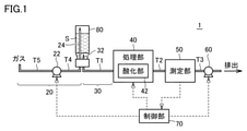
- FIG. 1 It is a schematic diagram for demonstrating the whole structure of inspection apparatus 1. It is a figure for demonstrating the method of attaching the sample tube 80 to the inspection apparatus 1. It is a flowchart which showed an example of the inspection process which a control unit 70 executes. It is a figure for demonstrating the method of attaching the sample tube 12 to the inspection apparatus which concerns on modification 1. FIG. It is a figure for demonstrating the state after attaching the sample tube 12 to the inspection apparatus which concerns on modification 1. FIG. It is a schematic diagram for demonstrating the structure of the inspection apparatus which concerns on modification 2. FIG.
- FIG. 1 is a schematic diagram for explaining the overall configuration of the inspection device 1.
- the inspection device 1 is a device for measuring the TOC amount (TOC concentration) in the sample water.
- the inspection device 1 is a so-called wet oxidation type inspection device that oxidizes organic substances in the sample water by irradiating the sample water with ultraviolet rays.
- the inspection device 1 includes an air supply unit 20, a sampling unit 30, a processing unit 40, a measuring unit 50, a liquid feeding unit 60, and a control unit 70.
- the air supply unit 20 sends gas into the sample tube 80 to pressurize the inside of the sample tube 80.
- the air supply unit 20 includes a pressurizing pump 22 and a gas needle 24.
- the pressurizing pump 22 generates a driving force for sending gas into the sample tube 80.
- the gas needle 24 is inserted into the sample tube 80 and introduces the gas sent by the pressurizing pump 22 into the sample tube 80.
- the pressurizing pump 22 and the gas needle 24 are connected via a tube T4.
- the pressurizing pump 22 takes in gas through the tube T5 connected to the pressurizing pump 22.
- the gas may be, for example, an atmosphere but a gas different from the atmosphere.
- the sampling unit 30 is configured to collect the sample water S stored in the sample tube 80.
- the sampling unit 30 includes a suction needle 32 that is inserted into the sample tube 80.
- the suction needle 32 is a needle for sucking the sample water S in the sample tube 80, and is connected to the processing unit 40 via the tube T1.
- the processing unit 40 processes the collected sample water.
- the processing unit 40 includes an oxidizing unit 42 for oxidizing the sample water S.
- the oxidizing portion 42 is a UV light source, and although not shown, includes an inner tube through which the sample water S passes through the internal space, and an outer tube arranged at intervals on the outer periphery of the inner tube.
- the discharge gas is sealed in the discharge space between the outer pipe and the inner pipe.
- Ultraviolet rays generated by exciting the discharge gas irradiate the internal space of the inner tube. That is, the oxidized portion 42 is a double-cylinder type excimer lamp.
- the treatment unit 40 may be any one that treats the collected sample water, and may be, for example, one that performs a treatment for adding a reagent to the sample water. Further, the oxidizing unit 42 oxidizes the organic matter in the sample water S by irradiating the sample water with ultraviolet rays, but for example, the sample water S may be chemically oxidized using an oxidizing agent or the like. ..
- the suction needle 32 and the upstream side of the inner tube of the oxidizing portion 42 are connected by a tube T1. Further, a tube T2 is connected to the downstream side of the inner tube of the oxidizing portion 42.
- the inner pipe can be said to be a part of the flow path through which the sample water S passes.
- the measuring unit 50 is a conductivity meter that measures the conductivity of the sample water S after being processed by the processing unit 40, and includes a flow path that can be connected to the tube T2.
- a tube T3 is connected to the downstream side of the flow path provided in the measuring unit 50. That is, the sample water S that has passed through the tube T2 flows into the measuring unit 50, and the sample water S that has passed through the measuring unit 50 is discharged through the tube T3.
- the measuring unit 50 includes a pair of electrodes arranged on the flow path provided in the measuring unit 50 so as to be in contact with the sample water S, and measures the conductivity of the sample water S by the two-terminal method.
- the measuring unit 50 may be any as long as it measures an index indicating the conductivity of the sample water, and is not limited to measuring the conductivity.
- the measuring unit 50 may measure the resistivity.
- the measuring unit 50 is provided with two electrodes as an example, but is provided with four electrodes and measures the conductivity of the sample water by another method such as a four-probe method or a four-terminal method. You may.
- the liquid feeding unit 60 generates a driving force to send the sample water S in the sample tube 80 to the measuring unit 50.
- the liquid feeding unit 60 is a pump, and as an example, it is connected to a tube T3 on the downstream side of the measuring unit 50.
- the liquid feeding unit 60 may be arranged, for example, on the upstream side of the measuring unit 50.
- the control unit 70 controls the entire inspection device 1. Although not shown, the control unit 70 has a CPU (Central Processing Unit), a storage unit for storing programs and data, and a communication I / F (Interface) as main components. The components are interconnected by a data bus.
- CPU Central Processing Unit
- storage unit for storing programs and data
- I / F Interface
- the components are interconnected by a data bus.
- the storage unit includes a ROM (Read Only Memory), a RAM (Random Access Memory), and an HDD (Hard Disk Drive).
- the ROM stores a program executed by the CPU.
- the RAM temporarily stores the data generated by the execution of the program in the CPU and the data input via the communication I / F.
- the RAM can function as a temporary data memory used as a work area.
- the HDD is a non-volatile storage device. Further, instead of the HDD, a semiconductor storage device such as a flash memory may be adopted.
- the program stored in the ROM may be stored in the storage medium and distributed as a program product.
- the program may be provided by an information provider as a program product that can be downloaded via the so-called Internet or the like.
- the storage medium is not limited to DVD-ROM (Digital Versatile Disk Read Only Memory), CD-ROM (compact disc read-only memory), FD (Flexible Disk), and hard disk, but also magnetic tape, cassette tape, and optical disc (MO (Magnetic)).
- Semiconductors such as Optical Disc) / MD (Mini Disc) / DVD (Digital Versatile Disc)), optical card, mask ROM, EPROM (Electronically Programmable Read-Only Memory), EEPROM (Electronically Erasable Programmable Read-Only Memory), flash ROM, etc. It may be a medium such as a memory that carries a fixed program.
- the recording medium is a non-temporary medium in which a computer can read a program or the like.
- the control unit 70 controls the operations of the air supply unit 20 and the liquid supply unit 60 so that the sample water S is sent to the measurement unit 50 in a state where the inside of the sample tube 80 is pressurized with gas.
- the solubility of the gas in the sample water S can be increased.
- the generation of gas during liquid feeding can be prevented, and the conductivity of the sample water S can be stably measured.
- control unit 70 controls the processing unit 40 to cause the processing unit 40 to process the sample water S, receives the detected value from the measuring unit 50, and performs a process of measuring the conductivity of the sample water S.
- the control unit 70 may maintain the pressure in the sample tube 80 at a state higher than the atmospheric pressure.
- the sample water S is oxidized by the oxidizing unit 42 to generate a decomposition product, so that the gas concentration in the flow path to the measuring unit 50 increases. Therefore, by increasing the solubility of the gas in the sample water S by setting the pressure in the sample tube 80 to be higher than the atmospheric pressure, even if the gas concentration in the flow path increases, the gas is discharged during the liquid feeding. It can be prevented from occurring.
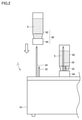
- FIG. 2 is a diagram for explaining a method of attaching the sample tube 80 to the inspection device 1.
- the direction of gravity is the bottom and the opposite direction is the top.
- the gas needle 24 is fixed to the housing 10 of the inspection device 1 so that the gas ejection port of the gas needle 24 faces upward.
- the suction needle 32 is fixed to the housing 10 of the inspection device 1 so that the suction port of the suction needle 32 faces upward.
- a pressurizing pump 22, a processing unit 40, a measuring unit 50, a liquid feeding unit 60, a control unit 70, and tubes T1 to T5 connecting them are arranged in the housing 10. There is.
- the sample tube 80 includes a main body 82 and a cap 84.
- the cap 84 is made of rubber. Therefore, the gas needle 24 and the suction needle 32 can be passed through the cap 84.
- the user may use the housing 10 with the sample tube 80 facing down with the cap 84 of the sample tube 80 facing down so that the suction needle 32 and the gas needle 24 penetrate the cap 84.
- the sample tube 80 can be attached to the inspection device 1 by pressing the sample tube 80 against the inspection device 1.
- the user presses the sample tube 80 from the top to the bottom against the housing 10.
- the sample tube 80 can be attached to the inspection device 1.
- it is sufficient to move the sample tube 80 in the direction of gravity, so that the sample tube 80 can be easily attached.
- the gas needle 24 is longer than the suction needle 32, and the length at which the gas outlet of the gas needle 24 is located above the liquid level of the sample water S when the sample tube 80 is attached to the inspection device 1. That's right.
- the suction needle 32 is shorter than the gas needle 24, and has a length in which the suction port of the sample water S of the suction needle 32 is located in the sample water S when the sample tube 80 is attached to the inspection device 1. Is.
- the length of the gas needle 24 is set so that the gas outlet of the gas needle 24 is located above the liquid level of the sample water S when the sample tube 80 is attached to the inspection device 1. This makes it possible to prevent bubbles from being generated in the sample tube 80. By preventing the generation of air bubbles in the sample tube 80, it is possible to prevent the air bubbles from being sent to the measuring unit 50 through the suction needle 32. Further, by preventing the generation of bubbles in the sample tube 80, the contact area between the gas and the sample water S can be reduced, and the generation of contamination can be suppressed.
- FIG. 3 is a flowchart showing an example of the inspection process executed by the control unit 70.
- the inspection process is, for example, a process realized by the CPU of the control unit 70 executing a program.
- control unit 70 determines whether or not the inspection start instruction has been accepted, and if not, ends the inspection process (NO in S100).
- the start instruction is received, for example, by the user attaching the sample tube 80 to the housing 10 and operating a start switch (not shown).
- the control unit 70 executes the process of S120.
- control unit 70 sends gas into the sample tube 80 to pressurize it. More specifically, the control unit 70 instructs the control unit 70 to send the gas into the sample tube 80 to drive the pressurizing pump 22. At this time, the flow rate of the gas sent into the sample tube 80 by the air supply unit 20 is larger than the flow rate of the sample water S sent from the sample tube 80 to the processing unit 40. In S120, the control unit 70 may not drive the liquid feeding unit 60 in order to prevent the sample water S from being sent from the sample tube 80 to the processing unit 40.
- the control unit 70 collects the sample water S. More specifically, the control unit 70 drives the liquid feeding unit 60 so that the sample water S is sucked into the suction needle 32 from the suction port of the suction needle 32. At this time, it is preferable that the flow rate of the sample water S sucked into the suction needle 32 is controlled to be about the same as the flow rate of the gas sent into the sample tube 80 by the air supply unit 20. By controlling in this way, the pressure applied in S120 can be maintained.
- the control unit 70 processes the collected sample water S. More specifically, the control unit 70 instructs the treatment unit 40 to perform a treatment for oxidizing the sample water S. In the present embodiment, the control unit 70 instructs the oxidizing unit 42 of the processing unit 40 to start irradiating the oxidized unit 42 with ultraviolet rays. The treatment of S160 is started at the timing when the collected sample water S passes through the tube T1 and reaches the oxidizing portion 42. Further, while the process of S160 is being executed, the control unit 70 drives the air supply unit 20 (pressurizing pump 22) and the liquid feeding unit 60 so that the sample water S stays in the oxidizing unit 42. It is preferable to stop.
- the control unit 70 sends the sample water S to the measurement unit 50 in a state where the inside of the sample tube 80 is pressurized with gas.
- the control unit 70 controls the air supply unit 20 and the liquid supply unit 60 so that the flow rate of the gas sent into the sample tube 80 and the flow rate of the sample water S sent to the measurement unit 50 are the same.
- the sample water S can be sent to the measuring unit 50 while maintaining the pressure applied in S120.
- the pressure loss occurs when the sample water S flows in the flow path. Therefore, the pressure applied to the sample water S reaching the measuring unit 50 is lower than the pressure applied to the sample water S in the sample tube 80.
- control unit 70 may control the air supply unit 20 and the liquid supply unit 60 so that the flow rate of the gas sent into the sample tube 80 is larger than the flow rate of the sample water S sent to the measurement unit 50.
- control unit 70 measures the conductivity of the sample water S. More specifically, the control unit 70 receives the detection value detected by the measurement unit 50. The process of S180 and the process of S200 may be executed at the same time.
- connection portion is not limited to the configuration according to the above embodiment.
- FIG. 4 is a diagram for explaining a method of attaching the sample tube 80 to the inspection device according to the modified example 1.
- FIG. 5 is a diagram for explaining a state after the sample tube 80 is attached to the inspection device according to the modified example 1.
- the inspection device according to the first modification includes the gas needle 24a and the suction needle 32a in place of the gas needle 24 and the suction needle 32, and the inspection device according to the above embodiment. Different from 1.
- the gas needle 24a and the suction needle 32a are different from the gas needle 24 and the suction needle 32 of the above-described embodiment in that the gas needle 24a is shorter than the suction needle 32a.
- the inspection device includes a fixing portion 90 for fixing the gas needle 24a and the suction needle 32a, a gas soft tube 25a connected to the gas needle 24a, and a suction needle 32a. Further provided with a connected soft suction tube 33a.
- the suction soft tube 33a is connected to the tube T1 connected to the processing unit 40 arranged in the housing 10. That is, the suction needle 32a is connected to the tube T1 that introduces the sample water S into the processing unit 40 via the suction soft tube 33a.
- the soft gas tube 25a is connected to the tube T4 connected to the pressurizing pump 22 arranged in the housing 10. That is, the gas needle 24a is connected to the tube T4 through which the gas from the pressurizing pump 22 passes through the gas soft tube 25a.
- the inspection device further includes a cylinder 92 formed around the suction needle 32a and the gas needle 24a.
- the cylinder 92 is provided with a fixing portion 90 at one end, and the other end is open.
- the cylinder 92 is moved from top to bottom with the cap 84 facing up.
- the suction needle 32a and the gas needle 24a are penetrated through the cap 84. Then, the sample tube 80 is attached to the inspection device.
- the inspection device further includes a holder 94 and a base 96 attached to the housing 10.
- the holder 94 fixes the cylinder 92.
- the base 96 functions as an installation place for installing the sample tube 80 when the cylinder 92 is attached to the holder 94.
- the gas needle 24a is shorter than the suction needle 32a, and has a length in which the gas outlet of the gas needle 24a is located above the liquid level of the sample water S when the sample tube 80 is attached to the inspection device. Is.
- the suction needle 32a is longer than the gas needle 24a, and when the sample tube 80 is attached to the inspection device, the suction port of the sample water S of the suction needle 32a is located in the sample water S. be.
- the sample tube 80 is attached to the needle from below each needle. Since the spout of the gas needle 24a is located above the liquid level of the sample water S when mounted, the sample water S does not come into contact with the spout of the gas needle 24a during the mounting work. Therefore, it is possible to prevent contamination from occurring from the gas needle 24a side when the sample tube 80 is replaced with another sample water S in which the sample water S is stored.
- the suction needle 32a and the gas needle 24a are connected to the tubes T1 and T4 via the suction soft tube 33a and the gas soft tube 25a. Further, the suction needle 32a and the gas needle 24a are fixed to the fixing portion 90. Therefore, the suction needle 32a and the gas needle 24a can be moved together, and the needle can be easily penetrated through the sample tube 80.
- the inspection device 1 according to the above embodiment may further include a filter for removing substances in the atmosphere. Further, the inspection device 1 according to the above embodiment may further include a pressure gauge for measuring the pressure applied on the flow path from the pressurizing pump 22 to the liquid feeding unit 60.
- FIG. 6 is a schematic diagram for explaining the configuration of the inspection device according to the modified example 2.
- the description of the configuration common to the inspection device 1 according to the above embodiment is omitted.
- the inspection device according to the second modification further includes a filter 26 and a pressure gauge 28.
- the filter 26 removes substances that affect the measurement of conductivity from the gas sent into the sample tube 80.
- the filter 26 removes carbon dioxide in the atmosphere.
- the filter 26 may remove volatile organic carbon in place of or in addition to carbon dioxide. It should be noted that the filter 26 may be able to remove at least a part of carbon dioxide and organic carbon even if it cannot be completely removed. As a result, contamination from the atmosphere can be prevented, and more accurate conductivity measurement can be performed.
- the filter 26 may be arranged upstream of the sample tube 80, and may be arranged upstream of the pressurizing pump 22, for example.
- the pressure gauge 28 measures at least a part of the pressure applied to the flow path from the pressurizing pump 22 (air supply unit) to the measuring unit 50.
- the pressure gauge 28 is arranged between the filter 26 and the sample tube 80, and measures the pressure applied to the flow path between the pressurizing pump 22 and the sample tube 80.
- the pressure gauge 28 may be arranged on any of the flow paths from the pressurizing pump 22 (air supply unit) to the measuring unit 50.
- control unit 70 may control the pressurizing pump 22 and the liquid feeding unit 60 according to the measurement result of the pressure gauge 28. Further, by arranging the pressure gauge 28, the user can test the leakage in the flow path from the pressurizing pump 22 to the measuring unit 50. For example, after the pressure applied to the flow path is set to a predetermined value by the pressurizing pump 22, the change with time of the pressure is measured by the pressure gauge 28 with the pressurizing pump 22 and the liquid feeding unit 60 stopped. Leakage in the flow path can be tested based on changes in pressure over time.
- the inspection device receives a sample tube in which sample water is stored, and has a sampling unit configured to collect sample water, a processing unit for treating the collected sample water, and a treatment unit.
- a measuring unit that measures the conductivity of the sample water, an inflow pipe for introducing the sample water into the measuring unit, a liquid feeding unit that generates a driving force to send the sample water in the sample tube to the measuring unit, and the inside of the sample tube. It is provided with an air supply unit for sending gas to pressurize, and a control unit for controlling the operation of the liquid supply unit and the air supply unit.
- the control unit controls the operation of the liquid feeding unit and the air supply unit, and sends the sample water to the measuring unit through the inflow pipe in a state where the inside of the sample tube is pressurized with gas.
- the solubility of the gas in the sample water can be increased by sending the sample water to the measuring unit in a state where the inside of the sample tube is pressurized with the gas.
- the generation of gas during liquid feeding can be prevented, and the conductivity of the sample water can be stably measured.
- the processing unit includes an oxidizing unit for oxidizing the sample water.
- the control unit controls the operation of the liquid feeding unit and the air supply unit to keep the pressure in the sample tube higher than the atmospheric pressure.
- the sample water is oxidized by the oxidizing part to generate a decomposition product, so that the gas concentration in the flow path to the measuring part increases, but the pressure is increased to increase the sample.
- the solubility of the gas in water it is possible to prevent the generation of gas during the liquid transfer.
- the inspection device according to paragraph 1 or 2 further includes a pressure gauge that measures at least a part of the pressure applied to the flow path from the air supply unit to the measurement unit.
- the pressure gauge is provided so as to test the leakage in the flow path or to send the measurement result of the pressure gauge to the control unit.
- the air supply unit and the measurement unit can be controlled according to the measurement result.
- the air supply unit includes a filter that removes a substance that changes the conductivity of the sample water from the gas.
- the sampling unit is inserted into the sample tube and includes a suction needle for collecting the sample water in the sample tube. ..
- the air supply unit is inserted into the sample tube and includes a gas needle for introducing gas into the sample tube. The length of the gas needle is shorter than the length of the suction needle.
- the sample tube and the connection portion can be connected without contacting the gas needle with the sample water, and another sample can be connected. It is possible to prevent contamination from occurring from the gas needle side when the sample tube is replaced with water.
- the inspection device further includes a fixing portion for fixing the suction needle and the gas needle.
- the sampling section further includes a soft suction tube connected to the suction needle.
- the air supply further includes a soft gas tube connected to the gas needle.
- the suction needle and the gas needle can be moved together, and the needle can be easily inserted into the sample tube.
- the inspection method is a step of sending gas into a sample tube containing sample water to pressurize it, a step of collecting sample water from the sample tube, and a step of treating the collected sample water.
- the solubility of the gas in the sample water can be increased by sending the sample water to the measuring unit in a state where the inside of the sample tube is pressurized with the gas.
- the generation of gas during liquid feeding can be prevented, and the conductivity of the sample water can be stably measured.
- 1 Inspection device 10 housing, 20 air supply part, 22 pressure pump, 24, 24a gas needle, 25a gas soft tube, 26 filter, 28 pressure gauge, 30 sampling part, 32, 32a suction needle, 33a Soft tube for suction, 40 processing part, 42 oxidizing part, 50 measuring part, 60 liquid feeding part, 70 control part, 80 sample tube, 82 main body, 84 cap, 90 fixing part, 92 cylinder, 94 holder, 96 units, S Sample water.
Landscapes
- Life Sciences & Earth Sciences (AREA)
- Chemical & Material Sciences (AREA)
- Health & Medical Sciences (AREA)
- Pathology (AREA)
- General Physics & Mathematics (AREA)
- Immunology (AREA)
- Physics & Mathematics (AREA)
- Analytical Chemistry (AREA)
- Biochemistry (AREA)
- General Health & Medical Sciences (AREA)
- Food Science & Technology (AREA)
- Medicinal Chemistry (AREA)
- Engineering & Computer Science (AREA)
- Hydrology & Water Resources (AREA)
- Chemical Kinetics & Catalysis (AREA)
- Electrochemistry (AREA)
- Investigating Or Analyzing Materials By The Use Of Electric Means (AREA)
- Sampling And Sample Adjustment (AREA)
- Investigating Or Analyzing Non-Biological Materials By The Use Of Chemical Means (AREA)
Abstract
Description
図1は、検査装置1の全体構成を説明するための模式図である。検査装置1は、試料水中のTOC量(TOCの濃度)を測定するための装置である。検査装置1は、試料水に紫外線を照射することで試料水中の有機物を酸化させる、いわゆる湿式酸化式の検査装置である。
図2は、検査装置1に試料管80を取り付ける方法を説明するための図である。なお、以下では、重力方向を下とし、その反対方向を上とする。図2を参照して、ガス用ニードル24は、ガス用ニードル24のガスの噴出口が上を向くように、検査装置1の筐体10に固定されている。同様に、吸引用ニードル32は、吸引用ニードル32の吸引口が上を向くように、検査装置1の筐体10に固定されている。また、筐体10内には、図示していないものの、加圧ポンプ22、処理部40、測定部50、送液部60、制御部70、およびこれらをつなぐチューブT1~チューブT5が配置されている。
図3は、制御部70が実行する検査処理の一例を示したフローチャートである。検査処理は、たとえば、制御部70のCPUがプログラムを実行することで実現する処理である。
上記実施の形態において、吸引用ニードル32およびガス用ニードル24を筐体10に固定させ、試料管80を上から下に向けて筐体10に押し付けることで、試料管80を検査装置1に取り付けるものとした。なお、接続部の構成は、上記実施の形態にかかる構成に限られない。
ガス用ニードル24aおよび吸引用ニードル32aは、ガス用ニードル24aの方が吸引用ニードル32aよりも短い点で、上記実施の形態のガス用ニードル24および吸引用ニードル32と異なる。
上記実施の形態にかかる検査装置1は、大気中の物質を除去するためのフィルタをさらに備えていてもよい。また、上記実施の形態にかかる検査装置1は、加圧ポンプ22から送液部60までの流路上にかかる圧力を測定する圧力計をさらに備えていてもよい。
上述した実施の形態は、以下の態様の具体例であることが当業者により理解される。
Claims (7)
- 試料水が格納された試料管を受け、前記試料水を採取するように構成されたサンプリング部と、
採取した前記試料水を処理する処理部と、
処理された前記試料水の導電性を測定する測定部と、
前記測定部に前記試料水を導入するための流入管と、
前記試料管内の前記試料水を前記測定部に送る駆動力を発生させる送液部と、
前記試料管内にガスを送って加圧するための給気部と、
前記送液部および前記給気部の動作を制御する制御部とを備え、
前記制御部は、前記送液部および前記給気部の動作を制御して、前記試料管内を前記ガスで加圧した状態で前記流入管を通じて前記測定部に前記試料水を送る、検査装置。 - 前記処理部は、前記試料水を酸化させるための酸化部を含み、
前記制御部は、前記送液部および前記給気部の動作を制御して、前記試料管内の圧力を大気圧より高い圧力に保つ、請求項1に記載の検査装置。 - 前記給気部から前記測定部までの流路にかかる少なくとも一部の圧力を測定する圧力計をさらに備える、請求項1または請求項2に記載の検査装置。
- 前記給気部は、前記試料水の導電性を変化させる物質を前記ガスから除去するフィルタを含む、請求項1~請求項3のうちいずれか1項に記載の検査装置。
- 前記サンプリング部は、前記試料管内に挿入され、前記試料管内の前記試料水を採取するための吸引用ニードルを含み、
前記給気部は、前記試料管内に挿入され、前記試料管内に前記ガスを導入するためのガス用ニードルを含み、
前記ガス用ニードルの長さは、前記吸引用ニードルの長さよりも短い、請求項1~請求項4のうちいずれか1項に記載の検査装置。 - 前記吸引用ニードルと前記ガス用ニードルとを固定するための固定部をさらに備え、
前記サンプリング部は、前記吸引用ニードルに接続された吸引用軟質チューブをさらに含み、
前記給気部は、前記ガス用ニードルに接続されたガス用軟質チューブとをさらに含む、請求項5に記載の検査装置。 - 試料水が格納された試料管内にガスを送って加圧するステップと、
前記試料管から前記試料水を採取するステップと、
採取された前記試料水を処理するステップと、
前記試料管内を前記ガスで加圧した状態で、処理された前記試料水の導電性を測定するための測定部に前記試料水を送るステップと、
前記測定部に送られた前記試料水の導電性を測定するステップとを含む、検査方法。
Priority Applications (4)
| Application Number | Priority Date | Filing Date | Title |
|---|---|---|---|
| EP21857990.2A EP4202435A4 (en) | 2020-08-20 | 2021-05-06 | INSPECTION DEVICE AND METHOD |
| CN202180051081.6A CN115885178B (zh) | 2020-08-20 | 2021-05-06 | 检查装置和检查方法 |
| JP2022543278A JP7480849B2 (ja) | 2020-08-20 | 2021-05-06 | 検査装置および検査方法 |
| US18/041,748 US12510526B2 (en) | 2020-08-20 | 2021-05-06 | Inspection apparatus and inspection method |
Applications Claiming Priority (2)
| Application Number | Priority Date | Filing Date | Title |
|---|---|---|---|
| JP2020139349 | 2020-08-20 | ||
| JP2020-139349 | 2020-08-20 |
Publications (1)
| Publication Number | Publication Date |
|---|---|
| WO2022038838A1 true WO2022038838A1 (ja) | 2022-02-24 |
Family
ID=80322853
Family Applications (1)
| Application Number | Title | Priority Date | Filing Date |
|---|---|---|---|
| PCT/JP2021/017325 Ceased WO2022038838A1 (ja) | 2020-08-20 | 2021-05-06 | 検査装置および検査方法 |
Country Status (5)
| Country | Link |
|---|---|
| US (1) | US12510526B2 (ja) |
| EP (1) | EP4202435A4 (ja) |
| JP (1) | JP7480849B2 (ja) |
| CN (1) | CN115885178B (ja) |
| WO (1) | WO2022038838A1 (ja) |
Families Citing this family (1)
| Publication number | Priority date | Publication date | Assignee | Title |
|---|---|---|---|---|
| CN119534041B (zh) * | 2025-01-23 | 2025-05-30 | 达那喜环境科技有限公司 | 一种基于环境保护的水质检测用多点取样装置 |
Citations (4)
| Publication number | Priority date | Publication date | Assignee | Title |
|---|---|---|---|---|
| JPH0256699B2 (ja) | 1982-04-05 | 1990-11-30 | Texas Instruments Inc | |
| JP2012202895A (ja) * | 2011-03-28 | 2012-10-22 | Shimadzu Corp | オートサンプラ及びそれを用いた全有機炭素計、ならびに液体試料採取方法 |
| JP2015028452A (ja) * | 2013-07-30 | 2015-02-12 | ジーエルサイエンス株式会社 | 試料導入方法および試料導入装置 |
| WO2016132526A1 (ja) * | 2015-02-20 | 2016-08-25 | 株式会社島津製作所 | 試料前処理装置及びこれを備えた分析装置、並びに、試料前処理方法 |
Family Cites Families (13)
| Publication number | Priority date | Publication date | Assignee | Title |
|---|---|---|---|---|
| US4666860A (en) * | 1984-01-10 | 1987-05-19 | Anatel Instrument Corporation | Instrument for measurement of the organic carbon content of water |
| US4769217A (en) * | 1985-04-29 | 1988-09-06 | Servomex Company | Apparatus for measuring content of organic carbon |
| WO1998003855A1 (en) * | 1996-07-05 | 1998-01-29 | Sievers Instruments, Inc. | Carbon monitoring system for water treatment and purification |
| JP3656441B2 (ja) * | 1998-12-24 | 2005-06-08 | 東亞合成株式会社 | 自動排水分析装置 |
| DE10196874B4 (de) | 2000-10-16 | 2012-04-26 | Sievers Instruments, Inc. | Analysator mit impulsförmiger Strömung zur Analyse der Gesamtmenge an organisch gebundenem Kohlenstoff |
| US7999003B2 (en) * | 2003-08-26 | 2011-08-16 | Mannatech, Incorporated | Antioxidant compositions and methods thereto |
| JPWO2007129383A1 (ja) * | 2006-05-01 | 2009-09-17 | 株式会社島津製作所 | 全有機体炭素測定装置 |
| CN101636652B (zh) * | 2007-03-20 | 2013-01-09 | 株式会社岛津制作所 | 总有机碳测定装置 |
| JP2009162536A (ja) * | 2007-12-28 | 2009-07-23 | Yaskawa Electric Corp | 液体試料分注装置および駆動方法 |
| CN201286919Y (zh) * | 2008-11-07 | 2009-08-12 | 董会华 | 过压保护加压快速输液装置 |
| CN101612425B (zh) * | 2009-07-21 | 2011-06-22 | 中国人民解放军第四军医大学 | 一次性自动加温加压输液装置 |
| EP2803996A1 (fr) | 2013-05-15 | 2014-11-19 | Merck Patent GmbH | Dispositif de mesure de conductivité d'un liquide pour déterminer de très bas niveaux de carbone organique total (TOC) dans de l'eau pure et ultra-pure |
| EP3142614B1 (en) * | 2014-05-13 | 2022-03-23 | Johnson & Johnson Surgical Vision, Inc. | System for providing pressurized infusion |
-
2021
- 2021-05-06 US US18/041,748 patent/US12510526B2/en active Active
- 2021-05-06 EP EP21857990.2A patent/EP4202435A4/en active Pending
- 2021-05-06 JP JP2022543278A patent/JP7480849B2/ja active Active
- 2021-05-06 WO PCT/JP2021/017325 patent/WO2022038838A1/ja not_active Ceased
- 2021-05-06 CN CN202180051081.6A patent/CN115885178B/zh active Active
Patent Citations (4)
| Publication number | Priority date | Publication date | Assignee | Title |
|---|---|---|---|---|
| JPH0256699B2 (ja) | 1982-04-05 | 1990-11-30 | Texas Instruments Inc | |
| JP2012202895A (ja) * | 2011-03-28 | 2012-10-22 | Shimadzu Corp | オートサンプラ及びそれを用いた全有機炭素計、ならびに液体試料採取方法 |
| JP2015028452A (ja) * | 2013-07-30 | 2015-02-12 | ジーエルサイエンス株式会社 | 試料導入方法および試料導入装置 |
| WO2016132526A1 (ja) * | 2015-02-20 | 2016-08-25 | 株式会社島津製作所 | 試料前処理装置及びこれを備えた分析装置、並びに、試料前処理方法 |
Non-Patent Citations (1)
| Title |
|---|
| See also references of EP4202435A4 |
Also Published As
| Publication number | Publication date |
|---|---|
| CN115885178B (zh) | 2025-05-16 |
| US12510526B2 (en) | 2025-12-30 |
| EP4202435A4 (en) | 2024-09-11 |
| JP7480849B2 (ja) | 2024-05-10 |
| US20230349879A1 (en) | 2023-11-02 |
| EP4202435A1 (en) | 2023-06-28 |
| JPWO2022038838A1 (ja) | 2022-02-24 |
| CN115885178A (zh) | 2023-03-31 |
Similar Documents
| Publication | Publication Date | Title |
|---|---|---|
| KR100491071B1 (ko) | 대수 감소값 예측 방법 | |
| JPH08178918A (ja) | 血液サンプルのヘマトクリット値を測定する計数装置のための制御溶液キット | |
| US20070254374A1 (en) | Water quality analyzer | |
| WO2005100947A1 (ja) | 吸着性の高いガス成分を含む分析用排ガス採取方法 | |
| TWI610070B (zh) | 氫氣濃度的連續測量方法及使用該方法的氫氣濃度測量裝置 | |
| JP5182257B2 (ja) | 全有機体炭素測定装置 | |
| WO2022038838A1 (ja) | 検査装置および検査方法 | |
| JP5659968B2 (ja) | 水質分析計 | |
| US6723216B2 (en) | Method and apparatus for detection of a bubble in a liquid | |
| NL8105083A (nl) | Inrichting voor het bewaken van de partiele druk van gassen. | |
| JP3043305B2 (ja) | 半導体設備内の環境分析用イオンクロマトグラフィーシステム | |
| JP2006087988A (ja) | 光反応管内蔵型光反応装置及びこれを用いる水質モニタリング装置 | |
| JP4465482B2 (ja) | 匂い測定装置 | |
| JP4873420B2 (ja) | ガス濃度検出装置及びガス濃度検出方法 | |
| JPH05312766A (ja) | 血液試料中の酸素分圧に相関する電気的値を測定する方法及び装置 | |
| JP2008249443A (ja) | 分注プローブの洗浄方法および装置 | |
| CN111373250B (zh) | 使用氯作为活性碱测定塔中游离氯浓度的方法 | |
| JP4165341B2 (ja) | 赤外線ガス分析装置 | |
| CN114641688B (zh) | 总有机碳测定方法和总有机碳测定装置 | |
| JP4681433B2 (ja) | キャピラリ電気泳動装置 | |
| JPWO2020136944A1 (ja) | シリンジポンプによる液の吸入の有無を検出する方法、及びシリンジポンプを備えた装置 | |
| JP2005214649A (ja) | Toc測定装置 | |
| JP2004226098A (ja) | 流体変調式測定装置 | |
| JPH10277534A (ja) | 脱気装置 | |
| JPH0355088Y2 (ja) |
Legal Events
| Date | Code | Title | Description |
|---|---|---|---|
| 121 | Ep: the epo has been informed by wipo that ep was designated in this application |
Ref document number: 21857990 Country of ref document: EP Kind code of ref document: A1 |
|
| ENP | Entry into the national phase |
Ref document number: 2022543278 Country of ref document: JP Kind code of ref document: A |
|
| NENP | Non-entry into the national phase |
Ref country code: DE |
|
| ENP | Entry into the national phase |
Ref document number: 2021857990 Country of ref document: EP Effective date: 20230320 |
|
| WWG | Wipo information: grant in national office |
Ref document number: 202180051081.6 Country of ref document: CN |
|
| WWG | Wipo information: grant in national office |
Ref document number: 18041748 Country of ref document: US |