WO2022038938A1 - 触覚センシングシステム - Google Patents
触覚センシングシステム Download PDFInfo
- Publication number
- WO2022038938A1 WO2022038938A1 PCT/JP2021/026661 JP2021026661W WO2022038938A1 WO 2022038938 A1 WO2022038938 A1 WO 2022038938A1 JP 2021026661 W JP2021026661 W JP 2021026661W WO 2022038938 A1 WO2022038938 A1 WO 2022038938A1
- Authority
- WO
- WIPO (PCT)
- Prior art keywords
- value
- shear force
- calculated
- electrodes
- aggregate
- Prior art date
- Legal status (The legal status is an assumption and is not a legal conclusion. Google has not performed a legal analysis and makes no representation as to the accuracy of the status listed.)
- Ceased
Links
Images
















Classifications
-
- B—PERFORMING OPERATIONS; TRANSPORTING
- B25—HAND TOOLS; PORTABLE POWER-DRIVEN TOOLS; MANIPULATORS
- B25J—MANIPULATORS; CHAMBERS PROVIDED WITH MANIPULATION DEVICES
- B25J13/00—Controls for manipulators
- B25J13/08—Controls for manipulators by means of sensing devices, e.g. viewing or touching devices
- B25J13/081—Touching devices, e.g. pressure-sensitive
- B25J13/082—Grasping-force detectors
- B25J13/083—Grasping-force detectors fitted with slippage detectors
-
- G—PHYSICS
- G01—MEASURING; TESTING
- G01L—MEASURING FORCE, STRESS, TORQUE, WORK, MECHANICAL POWER, MECHANICAL EFFICIENCY, OR FLUID PRESSURE
- G01L5/00—Apparatus for, or methods of, measuring force, work, mechanical power, or torque, specially adapted for specific purposes
- G01L5/0061—Force sensors associated with industrial machines or actuators
-
- B—PERFORMING OPERATIONS; TRANSPORTING
- B25—HAND TOOLS; PORTABLE POWER-DRIVEN TOOLS; MANIPULATORS
- B25J—MANIPULATORS; CHAMBERS PROVIDED WITH MANIPULATION DEVICES
- B25J13/00—Controls for manipulators
- B25J13/08—Controls for manipulators by means of sensing devices, e.g. viewing or touching devices
- B25J13/081—Touching devices, e.g. pressure-sensitive
- B25J13/084—Tactile sensors
-
- B—PERFORMING OPERATIONS; TRANSPORTING
- B25—HAND TOOLS; PORTABLE POWER-DRIVEN TOOLS; MANIPULATORS
- B25J—MANIPULATORS; CHAMBERS PROVIDED WITH MANIPULATION DEVICES
- B25J15/00—Gripping heads and other end effectors
- B25J15/02—Gripping heads and other end effectors servo-actuated
- B25J15/0253—Gripping heads and other end effectors servo-actuated comprising parallel grippers
-
- B—PERFORMING OPERATIONS; TRANSPORTING
- B25—HAND TOOLS; PORTABLE POWER-DRIVEN TOOLS; MANIPULATORS
- B25J—MANIPULATORS; CHAMBERS PROVIDED WITH MANIPULATION DEVICES
- B25J9/00—Program-controlled manipulators
- B25J9/16—Program controls
- B25J9/1612—Program controls characterised by the hand, wrist, grip control
-
- G—PHYSICS
- G01—MEASURING; TESTING
- G01L—MEASURING FORCE, STRESS, TORQUE, WORK, MECHANICAL POWER, MECHANICAL EFFICIENCY, OR FLUID PRESSURE
- G01L1/00—Measuring force or stress, in general
- G01L1/14—Measuring force or stress, in general by measuring variations in capacitance or inductance of electrical elements, e.g. by measuring variations of frequency of electrical oscillators
- G01L1/142—Measuring force or stress, in general by measuring variations in capacitance or inductance of electrical elements, e.g. by measuring variations of frequency of electrical oscillators using capacitors
-
- G—PHYSICS
- G01—MEASURING; TESTING
- G01L—MEASURING FORCE, STRESS, TORQUE, WORK, MECHANICAL POWER, MECHANICAL EFFICIENCY, OR FLUID PRESSURE
- G01L1/00—Measuring force or stress, in general
- G01L1/14—Measuring force or stress, in general by measuring variations in capacitance or inductance of electrical elements, e.g. by measuring variations of frequency of electrical oscillators
- G01L1/142—Measuring force or stress, in general by measuring variations in capacitance or inductance of electrical elements, e.g. by measuring variations of frequency of electrical oscillators using capacitors
- G01L1/146—Measuring force or stress, in general by measuring variations in capacitance or inductance of electrical elements, e.g. by measuring variations of frequency of electrical oscillators using capacitors for measuring force distributions, e.g. using force arrays
-
- G—PHYSICS
- G01—MEASURING; TESTING
- G01L—MEASURING FORCE, STRESS, TORQUE, WORK, MECHANICAL POWER, MECHANICAL EFFICIENCY, OR FLUID PRESSURE
- G01L5/00—Apparatus for, or methods of, measuring force, work, mechanical power, or torque, specially adapted for specific purposes
- G01L5/16—Apparatus for, or methods of, measuring force, work, mechanical power, or torque, specially adapted for specific purposes for measuring several components of force
- G01L5/165—Apparatus for, or methods of, measuring force, work, mechanical power, or torque, specially adapted for specific purposes for measuring several components of force using variations in capacitance
-
- G—PHYSICS
- G01—MEASURING; TESTING
- G01L—MEASURING FORCE, STRESS, TORQUE, WORK, MECHANICAL POWER, MECHANICAL EFFICIENCY, OR FLUID PRESSURE
- G01L5/00—Apparatus for, or methods of, measuring force, work, mechanical power, or torque, specially adapted for specific purposes
- G01L5/22—Apparatus for, or methods of, measuring force, work, mechanical power, or torque, specially adapted for specific purposes for measuring the force applied to control members, e.g. control members of vehicles, triggers
- G01L5/226—Apparatus for, or methods of, measuring force, work, mechanical power, or torque, specially adapted for specific purposes for measuring the force applied to control members, e.g. control members of vehicles, triggers to manipulators, e.g. the force due to gripping
-
- G—PHYSICS
- G05—CONTROLLING; REGULATING
- G05B—CONTROL OR REGULATING SYSTEMS IN GENERAL; FUNCTIONAL ELEMENTS OF SUCH SYSTEMS; MONITORING OR TESTING ARRANGEMENTS FOR SUCH SYSTEMS OR ELEMENTS
- G05B2219/00—Program-control systems
- G05B2219/30—Nc systems
- G05B2219/39—Robotics, robotics to robotics hand
- G05B2219/39505—Control of gripping, grasping, contacting force, force distribution
-
- G—PHYSICS
- G05—CONTROLLING; REGULATING
- G05B—CONTROL OR REGULATING SYSTEMS IN GENERAL; FUNCTIONAL ELEMENTS OF SUCH SYSTEMS; MONITORING OR TESTING ARRANGEMENTS FOR SUCH SYSTEMS OR ELEMENTS
- G05B2219/00—Program-control systems
- G05B2219/30—Nc systems
- G05B2219/40—Robotics, robotics mapping to robotics vision
- G05B2219/40625—Tactile sensor
Definitions
- the technology disclosed in this application relates to a tactile sensing system.
- the following technology is known as a tactile sensing system including a tactile sensor that comes into contact with an object.
- Patent Document 1 includes a tactile sensor capable of outputting a signal according to a pressure distribution and a shear force distribution of a contact surface in contact with an object, and a touch including a microcontroller to which a signal output from the tactile sensor is input. Pad devices are disclosed.
- Patent Document 2 discloses a tactile detection technique including a tactile sensor capable of outputting a signal according to a pressure distribution and a shear force distribution of a contact surface in contact with an object, and an external power source connected to the tactile sensor. It has been disclosed.
- Patent Document 1 does not describe the specific use of the pressure distribution and the shear force distribution detected by the tactile sensor.
- Patent Document 2 describes that the above-mentioned tactile detection technique can be applied to a personal convenience robot capable of supporting human life, but the matter relating to a robot having a pair of gripping portions for gripping a work is described. Not listed.
- One aspect of the technique disclosed in the present application is to obtain a tactile sensing system capable of efficiently providing tactile information useful for controlling a robot to a controller that controls a robot having a pair of gripping portions. ..
- the work is provided on the facing surfaces of the pair of grip portions provided on the robot and gripped by the pair of grip portions.
- a pair of tactile sensors that come into contact with each other and an output unit electrically connected to the pair of tactile sensors are provided, and each of the tactile sensors has a contact surface with the work, and also has an elastic layer and the elastic layer.
- the first electrode layer is provided with a capacitive sensor unit having a laminated structure in which the first electrode layer and the second electrode layer located on both sides of the contact surface are laminated in the normal direction of the contact surface.
- the second electrode layer has one or more second electrodes, and two or more of the plurality of first electrodes are the second when viewed in the normal direction.
- the sensor unit outputs a plurality of signals corresponding to each of the plurality of first electrodes, and the output unit outputs all or a part of the plurality of signals. Based on this, the pressure values of the plurality of pressure detection positions in the contact surface are calculated, and all or part of the plurality of partially overlapping electrode signals corresponding to each of the plurality of partially superimposed electrodes among the plurality of signals.
- a tactile sensing system that calculates one aggregate shear force value for the entire contact surface based on the above, and outputs pressure distribution data representing each pressure value of the plurality of pressure detection positions and the aggregate shear force value data. Is provided.
- tactile information useful for controlling the robot can be efficiently provided to the controller that controls the robot having a pair of grip portions.
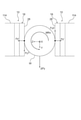
- FIG. 3 is a plan view showing a state in which the plurality of second electrodes, the elastic layer, and the substrate of FIG. 3 are overlapped with each other. It is a bottom view of the substrate of FIG. It is a figure explaining an example of the manufacturing method of the tactile sensor of FIG. It is a figure which shows the first example of the state which the work is gripped by the pair of gripping portions of FIG.
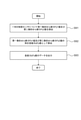
- FIG. 3 is a plan view illustrating an example of a translational force ⁇ Fx in the X-axis direction acting on a work gripped by a pair of gripping portions in FIG. 1. It is a flowchart which shows an example of the flow of the data output processing of the translational force ⁇ Fx value in the output part of FIG. FIG.
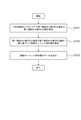
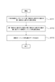
- FIG. 3 is a plan view illustrating an example of a translational force ⁇ Fy in the Y-axis direction acting on a work gripped by a pair of gripping portions in FIG. 1. It is a flowchart which shows an example of the flow of the data output processing of the translational force ⁇ Fy value in the output part of FIG. It is a flowchart which shows an example of the flow of the data output processing of the rotation moment MRx value in the output part of FIG. It is a flowchart which shows an example of the flow of the data output processing of the rotation moment MRy value in the output part of FIG. It is a vertical sectional view of the tactile sensor which concerns on 2nd Embodiment. It is a top view of the 2nd electrode layer of FIG. 32.
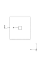
- FIG. 3 is a plan view showing a state in which the second electrode, the elastic layer, and the substrate of FIG. 32 are overlapped with each other. It is a figure explaining an example of the moment length in the tactile sensor of FIG. 32. It is a vertical sectional view of the tactile sensor which concerns on 3rd Embodiment. It is a top view of the 2nd electrode layer of FIG. 36.
- FIG. 3 is a plan view showing a state in which the second electrode, the elastic layer, and the substrate of FIG. 36 are overlapped with each other. It is a figure explaining an example of the moment length in the tactile sensor of FIG. 36. It is a vertical sectional view of the tactile sensor which concerns on 4th Embodiment. It is a top view of the 2nd electrode layer of FIG. 40.
- FIG. 3 is a plan view showing a state in which the second electrode, the elastic layer, and the substrate of FIG. 40 are overlapped with each other.
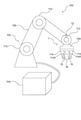
- FIG. 1 is a perspective view showing an example of the robot system 100.
- the robot system 100 includes a robot 102 and a controller 104.
- the robot 102 is, for example, an articulated robot, and includes a robot arm 106 and a robot hand 108.
- the robot arm 106 includes a plurality of joints 110.
- the robot hand 108 is provided at the tip of the robot arm 106.
- the robot hand 108 is connected to the tip of the robot arm 106 via the wrist joint portion 112.
- the robot hand 108 is provided with a pair of grip portions 114.
- the pair of grips 114 are arranged so as to face each other.
- the pair of grips 114 are brought into contact with each other in directions facing each other by driving a drive unit (not shown).
- a drive unit not shown.
- the controller 104 controls the robot 102 and is electrically connected to the robot 102.
- the controller 104 is connected to the robot 102 by wire, but the controller 104 may be wirelessly connected to the robot 102.
- the robot system 100 is equipped with a tactile sensing system 1.
- the tactile sensing system 1 includes a pair of tactile sensors 10 and an output unit 12.
- the pair of tactile sensors 10 are provided on the facing surfaces 114A of the pair of grip portions 114, respectively.
- the pair of tactile sensors 10 are provided at a position where the work W is in contact with the work W when the work W is gripped by the pair of grip portions 114, that is,, for example, at a portion of the tips of the pair of grip portions 114 facing each other. There is.
- the output unit 12 is electrically connected to the pair of tactile sensors 10.
- the output unit 12 may be connected to the pair of tactile sensors 10 by wire, or may be connected to the pair of tactile sensors 10 wirelessly.
- the output unit 12 has a function of performing various processes based on the data output from the pair of tactile sensors 10 and outputting the data based on the result of this process to the controller 104.
- the output unit 12 is provided on the wrist joint portion 112 as an example.
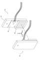
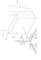
- FIG. 2 is a perspective view showing an example of the pair of tactile sensors 10 of FIG.
- the pair of tactile sensors 10 are plane-symmetrical in the directions facing each other.
- the X-axis direction corresponds to the first direction orthogonal to the direction in which the pair of tactile sensors 10 face each other
- the Y-axis direction corresponds to the second direction orthogonal to the direction in which the pair of tactile sensors 10 face each other, and the Z-axis direction.
- the direction corresponds to the direction in which the pair of tactile sensors 10 face each other.
- the X-axis direction is orthogonal to the Y-axis direction.
- the X-axis direction corresponds to the vertical direction of the tactile sensor 10
- the Y-axis direction corresponds to the horizontal direction of the tactile sensor 10.
- the tactile sensor 10 includes a support plate 14, a substrate 16, and a sensor unit 18.
- the support plate 14 is configured separately from the grip portion 114 (see FIG. 1) described above, and is fixed to the grip portion 114.
- the support plate 14 may be integrally configured with the grip portion 114.
- the substrate 16 is fixed to the support plate 14, and the sensor unit 18 is provided on the substrate 16. The details of the sensor unit 18 will be described in detail later.
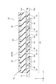
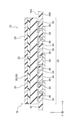
- FIG. 3 is a vertical sectional view of the tactile sensor 10 according to the first embodiment.
- the tactile sensor 10 according to the first embodiment includes a sensor unit 18 and a substrate 16.
- the sensor unit 18 is of a capacitance type. More specifically, the sensor unit 18 is a self-capacity method and has a laminated structure in which a plurality of layers are laminated. That is, the sensor unit 18 has an insulating layer 20, an elastic layer 22, a first electrode layer 24, and a second electrode layer 26 as a plurality of layers. The first electrode layer 24 and the second electrode layer 26 are located on both sides of the elastic layer 22.
- the insulating layer 20 is located on the opposite side of the elastic layer 22 with respect to the second electrode layer 26.
- the insulating layer 20 forms a surface layer portion of the sensor portion 18.
- the surface of the insulating layer 20 is formed as a contact surface 28 with the work W (see FIG. 1).
- the insulating layer 20 may be omitted. When the insulating layer 20 is omitted, the surface of the surface layer formed on the second electrode layer 26 and the second electrode layer 26 is referred to as the contact surface 28.
- the elastic layer 22 is a dielectric.
- the elastic layer 22 has flexibility and elasticity.
- the elastic layer 22 is formed by, for example, a gel.
- the insulating layer 20, the elastic layer 22, the first electrode layer 24, and the second electrode layer 26 are laminated in the Z-axis direction.
- the Z-axis direction corresponds to the normal direction of the contact surface 28.
- the insulating layer 20, the elastic layer 22, the first electrode layer 24, and the second electrode layer 26 are adhered to each other by, for example, an adhesive.
- the insulating layer 20 preferably has a size that covers the entire surface of the second electrode layer 26 in order to increase the adhesive strength of the entire sensor portion 18.
- the first electrode layer 24 has a plurality of first electrodes 34.
- the plurality of first electrodes 34 are formed on the first surface 16A on the sensor portion 18 side of the substrate 16.
- a plurality of capacitance detection ICs (Integrated Circuits) 44 are mounted on the second surface 16B on the side opposite to the sensor unit 18 of the substrate 16.
- the plurality of first electrodes 34 and the plurality of capacitance detection ICs 44 are connected by a through-hole via 46 extending in the plate thickness direction of the substrate 16.
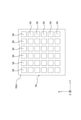
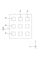
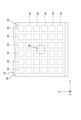
- FIG. 4 is a plan view of the substrate 16 of FIG.
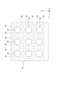
- the plurality of first electrodes 34 formed on the first surface 16A of the substrate 16 are arranged in a matrix along the XY plane. That is, the plurality of first electrodes 34 are arranged with the X-axis direction as the vertical direction and the Y-axis direction as the horizontal direction.
- the XY plane is a plane parallel to the above-mentioned contact surface 28 (see FIG. 2).
- the plurality of first electrodes 34 are independent of each other.
- the plurality of first electrodes 34 have the same shape.
- the plurality of first electrodes 34 are formed in a square shape in a plan view. Plane view corresponds to viewing in the Z-axis direction.
- the plurality of first electrodes 34 are arranged six by six in the X-axis direction and six by six in the Y-axis direction. That is, the number of the plurality of first electrodes 34 is 36.
- the plurality of first electrodes 34 are arranged at equal intervals in the X-axis direction and the Y-axis direction, respectively.
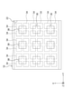
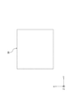
- FIG. 5 is a plan view of the second electrode layer 26 of FIG.
- the second electrode layer 26 is composed of a plurality of second electrodes 36 which are single layers.
- the plurality of second electrodes 36 are formed of, for example, conductive rubber.
- the plurality of second electrodes 36 are each formed in a flat plate shape.
- the plurality of second electrodes 36 may be connected to the ground of the substrate 16 or may float with respect to the ground.
- the plurality of second electrodes 36 form a plurality of islands independent of each other.
- the plurality of second electrodes 36 are arranged in a matrix along the XY plane. That is, the plurality of second electrodes 36 are arranged with the X-axis direction as the vertical direction and the Y-axis direction as the horizontal direction.
- the plurality of second electrodes 36 have the same shape.
- the plurality of second electrodes 36 are each formed into a square in a plan view.
- the number of the plurality of second electrodes 36 is smaller than the number of the plurality of first electrodes 34 (see FIG. 4) described above.
- the plurality of second electrodes 36 are arranged three by three in the X-axis direction and three by three in the Y-axis direction. That is, the number of the plurality of second electrodes 36 is nine.
- the plurality of second electrodes 36 are arranged at equal intervals in the X-axis direction and the Y-axis direction, respectively.
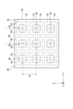
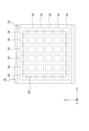
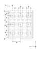
- FIG. 6 is a plan view showing a state in which the plurality of second electrodes 36 of FIG. 3, the elastic layer 22 and the substrate 16 are overlapped with each other.
- the plurality of second electrodes 36 are arranged so as to overlap all of the plurality of first electrodes 34 in a plan view.
- Each of the plurality of second electrodes 36 is formed so as to partially overlap each of the four first electrodes 34 adjacent to each other in the X-axis direction and the Y-axis direction among the plurality of first electrodes 34 in a plan view. There is.
- Each second electrode 36 is located at the center of the four first electrodes 34 in a plan view and partially overlaps with the four first electrodes 34.
- all of the plurality of first electrodes 34 partially overlap with the plurality of second electrodes 36.
- all of the plurality of first electrodes 34 correspond to an example of "a plurality of partially superimposed electrodes partially overlapping the plurality of second electrodes", and are output from the plurality of first electrodes 34.
- the plurality of signals correspond to an example of "plurality of partially overlapping electrode signals”.
- the capacitance C [F] between the first electrode 34 and the second electrode 36 is obtained by the following equation.
- C ⁇ ⁇ A / d ⁇ is the dielectric constant [Fm -1 ] of the elastic layer 22
- A is the area where the first electrode 34 and the second electrode 36 overlap in a plan view [m 2 ]
- d is the first along the Z-axis direction.
- the capacitance C changes according to the change in the distance d. Further, in the sensor unit 18, when a shearing force is applied to the contact surface 28 and the overlapping area A of the first electrode 34 and the second electrode 36 changes, the capacitance C changes according to the change in the area A.
- the pressure applied to the contact surface 28 corresponds to the force applied to the contact surface 28 along the Z-axis direction.
- the shearing force applied to the contact surface 28 corresponds to a force applied to the contact surface 28 along a direction orthogonal to the Z-axis direction.
- the direction orthogonal to the Z-axis direction includes an X-axis direction, a Y-axis direction, and a direction in which the X-axis direction and the Y-axis direction are combined.
- the plurality of first electrodes 34 are driven by the capacitance detection IC 44 (see FIGS. 3 and 7) described later, and output a signal corresponding to the capacitance C between the first electrode 34 and the second electrode 36. That is, the sensor unit 18 outputs a plurality of signals corresponding to each of the plurality of first electrodes 34.
- the plurality of signals are analog signals.
- FIG. 7 is a bottom view of the substrate 16 of FIG.
- the plurality of capacitance detection ICs 44 are arranged in a matrix along the XY plane. That is, the plurality of capacitance detection ICs 44 are arranged with the X-axis direction as the vertical direction and the Y-axis direction as the horizontal direction.
- the plurality of capacitance detection ICs 44 have the same configuration. As an example, the plurality of capacitance detection ICs 44 are arranged three by three in the X-axis direction and three by three in the Y-axis direction. That is, the number of the plurality of capacitance detection ICs 44 is nine.
- Each capacitance detection IC 44 is connected to four first electrodes 34 that overlap with the capacitance detection IC in a plan view.
- Each capacitance detection IC 44 has a configuration capable of driving four first electrodes 34 and outputting data corresponding to the signals output from the four first electrodes 34.
- FIG. 8 is a diagram illustrating an example of a method for manufacturing the tactile sensor 10 of FIG.
- the tactile sensor 10 is manufactured, for example, as follows. That is, a plurality of capacitance detection ICs 44 are mounted on the second surface 16B of the substrate 16 in which the plurality of first electrodes 34 are formed on the first surface 16A by the pattern. A plurality of through-hole vias 46 are formed on the substrate 16, and the plurality of capacitance detection ICs 44 are connected to the plurality of first electrodes 34 via the plurality of through-hole vias 46.
- the elastic layer 22 is laminated on the first electrode layer 24 having the plurality of first electrodes 34.
- a second electrode layer 26 composed of a plurality of second electrodes 36 (see FIG. 5) is laminated on the elastic layer 22, and an insulating layer 20 is further laminated on the second electrode layer 26.
- the insulating layer 20, the elastic layer 22, the first electrode layer 24, and the second electrode layer 26 are adhered to each other by, for example, an adhesive.
- the tactile sensor 10 is manufactured in the above manner.
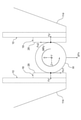
- FIG. 9 is a diagram showing a first example of a state in which the work W is gripped by the pair of gripping portions 114 of FIG.
- the work W is, for example, a cylinder or a sphere.
- FIG. 10 is a diagram showing a second example of a state in which the work W is gripped by the pair of gripping portions 114 of FIG.
- the work W is, for example, a quadrangular prism or a rectangular parallelepiped.
- the surface of the work W is larger than the contact surface 28.
- FIG. 11 is a diagram illustrating an example of shearing forces Fx, Fy and moments Mx, My, Mz acting on the contact surface 28 of the tactile sensor 10 of FIG.
- Shear forces Fx, Fy and moments Mx, My, Mz may act on the contact surface 28 of the tactile sensor 10 as a force acts on a work (not shown).
- the shear force Fx is a force along the X-axis direction
- the shear force Fy is a force along the Y-axis direction.
- the moment Mx is a moment around the X-axis direction
- the moment My is a moment around the Y-axis direction
- the moment Mz is a moment around the Z-axis direction.
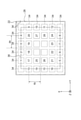
- FIG. 12 is a diagram illustrating an example of moment lengths dx and dy in the tactile sensor 10 of FIG.
- identification numbers 1 to 9 are shown for the plurality of second electrodes 36.
- each of the plurality of second electrodes 36 is referred to as a second electrode 36-1 to 9.
- the moment length dx shown in FIG. 12 is the length used when calculating the moment Mx (see FIG. 11) around the X-axis direction.
- the moment length dx corresponds to the distance along the Y-axis direction between the center of the second electrode 36-3 located away from the center of the contact surface 28 in the Y-axis direction and the center of the contact surface 28. do.
- the moment length dy shown in FIG. 12 is the length used when calculating the moment My (see FIG. 11) around the Y-axis direction.
- the moment length dy corresponds to the distance along the X-axis direction between the center of the second electrode 36-1 located away from the center of the contact surface 28 in the X-axis direction and the center of the contact surface 28. do.
- FIG. 13 is a plan view illustrating an example of the displacement ⁇ x and the displacement ⁇ y in the tactile sensor 10 of FIG.
- the capacitances C 00 to C 55 between each of the plurality of first electrodes 34 and the second electrode 36 are shown corresponding to each of the plurality of first electrodes 34.
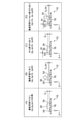
- FIG. 14 is a diagram illustrating an example of displacement ⁇ x and displacement ⁇ z in the tactile sensor 10 of FIG. 14 shows the cases of (A) without vertical load Fz', (B) with vertical load Fz', (C) with shear force Fx, and (D) with vertical load Fz'+ with shear force Fx, respectively. ing.
- FIG. 15 is a diagram illustrating an example of displacement ⁇ y and displacement ⁇ z in the tactile sensor 10 of FIG.
- FIG. 15 shows the cases of (A) without vertical load Fz', (B) with vertical load Fz', (C) with shear force Fy, and (D) with vertical load Fz'+ with shear force Fy, respectively. ing.
- the displacement ⁇ x corresponds to the distance that the second electrode 36 moves along the X-axis direction due to the action of the shear force Fx.
- the displacement ⁇ y corresponds to the distance that the second electrode 36 has moved along the Y-axis direction due to the action of the shearing force Fy.
- the distance Z 0 corresponds to the distance along the Z-axis direction between the first electrode 34 and the second electrode 36 when the vertical load Fz'is not applied. ..
- the displacement ⁇ z corresponds to the distance that the second electrode 36 moves toward the first electrode 34 along the Z-axis direction due to the action of the vertical load Fz'.
- Equation 1 holds.
- C 01_0 K2 / Z 0
- C 00_0 and C 01_0 are the capacitances between the adjacent first electrode 34 and the second electrode 36 when the vertical load Fz'is not acting, and K1 and K2 are constants.
- the same equation as in Equation 1 holds for the capacitance between the other adjacent first electrodes 34 and the second electrode 36.
- C 00_z K1 / (Z 0 - ⁇ z)
- C 01_z K2 / (Z 0 - ⁇ z)
- C 00_z and C 01_z are the capacitances between the adjacent first electrode 34 and the second electrode 36 when only the vertical load Fz'is applied.
- Equation 1 the following can be obtained for the displacement ⁇ z of the second electrode 36 with respect to one of the first electrodes 34.
- Z 0 K1 / C 00_0
- ⁇ z K1 (1 / C 00_0 -1 / C 00_z )
- ⁇ z K2 (1 / C 01_0 -1 / C 01_z )
- the displacement ⁇ z of the second electrode 36 with respect to the other first electrode 34 can also be obtained in the same manner as described above.
- C 00_x K1 / Z 0 + ⁇ x ⁇ Kp / Z 0
- C 01_x K2 / Z 0 - ⁇ x ⁇ Kp / Z 0
- C 00_x and C 01_x are the capacitances between the first electrode 34 and the second electrode 36 adjacent to each other in the x direction when only the shear force Fx is acting, and Kp is a constant.
- ⁇ x Z 0 / Kp ⁇ (C 01_0 -C 01_x )
- the displacement ⁇ x of the second electrode 36 with respect to the other first electrode 34 can also be obtained in the same manner as described above.
- C 00_zx K1 / (Z 0 - ⁇ z) + ⁇ x ⁇ Kp / (Z 0 - ⁇ z)
- C 01_zx K2 / (Z 0 - ⁇ z) - ⁇ x ⁇ Kp / (Z 0 - ⁇ z)
- C 00_zx and C 01_zx are the capacitances between the first electrode 34 and the second electrode 36 when only the vertical load Fz'and the shearing force Fx are acting.
- the displacements ⁇ z and ⁇ x of the second electrode 36 with respect to the other first electrodes 34 can also be obtained in the same manner as described above.
- the displacements ⁇ x, ⁇ y and ⁇ z of the second electrode 36 with respect to the first electrode 34 can be obtained as follows. In the range of the four first electrodes 34 that partially overlap the one second electrode 36, the values of the displacement ⁇ z in each of the first electrodes 34 are often close to each other, so that the values of the displacement ⁇ z are common. Suppose. In that case, the magnitude (capacitance value) of the signal corresponding to each first electrode 34 is proportional to the overlapping area of each first electrode 34 with the second electrode 36.
- Equation 6 the sum of the four overlapping areas is 4a 2 , which is a constant. Therefore, from the sum 4a 2 of the four overlapping areas and the equation 5, the overlapping areas S 00 , S 01 , S 10 and S 11 are known values. From the above, unknown displacements ⁇ x and ⁇ y can be calculated by the simultaneous equations of Equation 6.
- the displacements ⁇ z assumed to be common values may be corrected to the individual displacements ⁇ z in each first electrode 34 by using them as known values.
- This correction is performed by, for example, acquiring the correlation between the displacements ⁇ x and ⁇ y and the four displacements ⁇ z in advance in an environment where the true values of the four displacements ⁇ z can be measured by another means and using it. It can be carried out. The acquisition of this correlation may be performed by machine learning.
- the displacement ⁇ z in the four first electrodes 34 may be calculated individually by the method described.
- the displacements ⁇ x and ⁇ y mainly change while the displacement ⁇ z does not change so much. Therefore, it is possible to treat the displacement ⁇ z as a known value and obtain the displacements ⁇ x and ⁇ y more accurately. can.
- calculating the pressure value of each of the plurality of pressure detection positions is calculated when it is assumed that the displacement ⁇ z at the plurality of pressure detection positions such as the four first electrodes 34 is common. It includes treating the pressure value based on the common displacement ⁇ z as the pressure value at each pressure detection position. Further, “calculating the aggregated pressure value by calculating the representative value for each pressure value of the plurality of pressure detection positions” means that the displacement ⁇ z at the plurality of pressure detection positions such as the four first electrodes 34 is determined. This includes calculating the aggregated pressure value using the pressure value based on the calculated common displacement ⁇ z as a representative value when it is assumed to be common.
- the output unit 12 has a plurality of first electrodes 34 including at least one partially overlapping electrode which is a first electrode 34 whose shear force Fx and Fy values partially overlap with the second electrode 36. Based on the plurality of signals corresponding to each of the above, the calculation is made so as to eliminate the influence of the pressure on the plurality of signals.
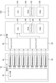
- FIG. 16 is a block diagram showing an example of the hardware configuration of the tactile sensor 10, the output unit 12, and the controller 104 of FIG.
- the output unit 12 includes a first multiplexer 50, a second multiplexer 52, a CPU (Central Processing Unit) 54, a ROM (Read Only Memory) 56, and a RAM (Random Access Memory) 58.
- a CPU Central Processing Unit
- ROM Read Only Memory
- RAM Random Access Memory
- a plurality of capacitance detection ICs 44 are connected to the first multiplexer 50 and the second multiplexer 52.
- the data output from the plurality of capacitance detection ICs 44 is input to the first multiplexer 50 and the second multiplexer 52.
- the first multiplexer 50 and the second multiplexer 52 are connected to the CPU 54.
- the data output from the first multiplexer 50 and the second multiplexer 52 is input to the CPU 54. Further, data output from the controller 104, which will be described later, is input to the CPU 54.
- the CPU 54 uses the RAM 58 as a primary storage area and executes the program 60 stored in the ROM 56. As will be described later, the program 60 records various processes for the CPU 54 to perform an operation based on the data output from the tactile sensor 10 and the data output from the controller 104 and output the data to the controller 104. ..
- the output unit 12 is connected to the controller 104 so as to be able to communicate by wire or wirelessly.
- the controller 104 includes a CPU 124, a ROM 126, and a RAM 128.
- the data output from the output unit 12 is input to the CPU 124.
- the CPU 124 uses the RAM 128 as a primary storage area and executes the program 130 stored in the ROM 126. As will be described later, the program 130 records various processes for outputting data such as the controller 104 moving the robot 102 and requesting data from the output unit 12.
- FIG. 17 is a diagram illustrating an example of a plurality of modes in the output unit 12 of FIG.
- the output unit 12 has a collision detection mode, an operation content determination mode, and a request command correspondence mode.
- the collision detection mode is a mode in which collision detection data is output to the controller 104 when a work collision is detected based on the data output from the tactile sensor 10.
- Work collision is the collision of an unexpected object with the work.
- the collision detection data includes, for example, in addition to the data indicating that a collision has been detected, the gripping force (aggregate pressure) Fz value data, the aggregate shear force Fx value data, and the aggregate shear force Fy value data, which will be described later. At least one may be selectively included.
- the output unit 12 outputs the collision detection data to the controller 104 regardless of the presence or absence of an instruction from the controller 104, and the controller 104 processes the collision detection data by interrupt processing.
- the pressure values of the plurality of pressure detection positions in the contact surface 28 are calculated, and at least a predetermined number of the pressure values of the plurality of pressure detection positions are calculated.
- the pressure value exceeds the threshold
- the aggregate pressure value described later exceeds the threshold
- the aggregate shear force Fx value described later exceeds the threshold
- the aggregate shear force Fy value described later exceeds the threshold.
- the collision of the work is detected.
- the operation content of the robot 102 is determined based on the data output from the controller 104, and the pressure distribution data, the gripping force Fz value data, and the aggregate shear force Fx value, which will be described later, are determined according to the operation content.
- the output unit 12 determines and determines which data is to be output according to the operation content of the robot 102.
- the operation content of the robot 102 is, for example, that the work W is grasped by the robot hand 108 shown in FIG. 1, the robot arm 106 moves so as to move the work W while grasping the work W by the robot hand 108, and the work W is The robot arm 106 moves so as to search for a moving destination while touching an object, the robot arm 106 moves so that the work W is inserted into the moving destination, and the robot hand 108 releases the work W. ..
- the pressure distribution data, the grip force Fz value data, the grip position data, and the aggregate shear force Fx value which will be described later, are set according to the request command included in the data output from the controller 104.
- the aggregate shear force Fy value data, the moment Mx value data, the moment My value data, and the moment Mz value data is selectively output.
- the request command response mode includes, for example, a gripping position detection mode, a gripping force detection mode, and an insertion feature amount detection mode.
- the gripping position detection mode is a mode designated by the controller 104 when the pair of gripping portions 114 shown in FIG. 1 grips the work W.
- This gripping position detection mode is a mode for outputting pressure distribution data or gripping position data.
- the gripping force detection mode is, for example, a mode designated by the controller 104 in the process of shifting from the open state to the closed state of the pair of gripping portions 114 shown in FIG.
- This gripping force detection mode is a mode for outputting data of the gripping force Fz value.
- the controller 104 detects the contact of the robot hand 108 with the work W, the contact maintenance detection of the robot hand 108 with the work W, and the fitting of the work W to the moving destination. Position detection, fitting position deviation detection of work W to the moving destination, insertion posture deviation detection of work W to moving destination, insertion completion detection of work W to moving destination, pulling completion completion detection of work W from moving destination, etc. This is the mode specified by the controller 104 when performing the above.
- grip force Fz value data as 6-axis information, grip force Fz value data, aggregate shear force Fx value data, aggregate shear force Fy value data, moment Mx value data, moment My value data, and This mode outputs data of the moment Mz value.
- the output unit 12 outputs the translational force ⁇ Fx value data, the translational force ⁇ Fy value data, or the rotation moment Mr value, which will be described later, as necessary.
- the output unit 12 outputs pressure distribution data representing the pressure values of the plurality of pressure detection positions in the contact surface 28.
- the pressure detection position is the position of each first electrode 34.
- the position of the first electrode 34 is represented by the position of a specific portion of the first electrode 34, such as the center of the first electrode 34 or any corner.
- the data output process of this pressure distribution is executed by the CPU 54 of the output unit 12 according to the following procedure, for example.
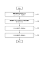
- FIG. 18 is a flowchart showing an example of the flow of pressure distribution data output processing in the output unit 12 of FIG.
- the CPU 54 acquires the data output from the plurality of capacitance detection ICs 44.
- the data acquired in this step S1 is the data of the signal output from the sensor unit 18 corresponding to the first electrode 34 for which the displacement ⁇ z is calculated in the step S2 described later.
- step S2 the CPU 54 calculates the displacement ⁇ z of each of the plurality of pressure detection positions in the contact surface 28 based on the data acquired in step S1.
- the displacement ⁇ z of each of the plurality of pressure detection positions corresponding to all of the plurality of first electrodes 34 may be calculated based on all the data of the plurality of signals output from the sensor unit 18.
- the displacement ⁇ z of each of the plurality of pressure detection positions corresponding to a part of the plurality of first electrodes 34 may be calculated based on the data of a part of the plurality of signals output from 18.
- the pressure detection position is from the signal corresponding to the four first electrodes 34 partially overlapping the one second electrode 36. Calculation of four ⁇ z at the positions of the four first electrodes 34 is performed for each second electrode 36.
- the displacement ⁇ z of each of the plurality of pressure detection positions calculated in this way is proportional to the pressure value of each of the plurality of pressure detection positions. Therefore, by calculating the displacement ⁇ z of each of the plurality of pressure detection positions, the pressure value of each of the plurality of pressure detection positions is calculated.
- step S3 the CPU 54 generates pressure distribution data based on the pressure values of the plurality of pressure detection positions in the contact surface 28 calculated in step S2.
- step S4 the CPU 54 outputs the pressure distribution data generated in step S3 to the controller 104.
- This pressure distribution data is used, for example, in the controller 104 to grasp the gripping position and gripping posture of the work W whose shape is known, and to identify the work W based on the shape.
- the output unit 12 identifies the gripping position of the work W in the contact surface 28 based on the pressure value of each of the plurality of pressure detection positions in the contact surface 28, and outputs the data of the gripping position.
- the data output process of the gripping position is executed by the CPU 54 of the output unit 12 according to the following procedure, for example.
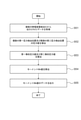
- FIG. 19 is a flowchart showing an example of the flow of data output processing of the gripping position in the output unit 12 of FIG.
- the CPU 54 acquires the data output from the plurality of capacitance detection ICs 44.
- the data acquired in this step S11 is the data of the signal output from the sensor unit 18 corresponding to the first electrode 34 for which the displacement ⁇ z is calculated in the step S12 described later.
- step S12 the CPU 54 calculates the displacement ⁇ z of each of the plurality of pressure detection positions in the contact surface 28 based on the data acquired in step S11.
- the displacement ⁇ z of each of the plurality of pressure detection positions corresponding to all of the plurality of first electrodes 34 may be calculated based on all the data of the plurality of signals output from the sensor unit 18.
- the displacement ⁇ z of each of the plurality of pressure detection positions corresponding to a part of the plurality of first electrodes 34 may be calculated based on the data of a part of the plurality of signals output from 18.
- the pressure detection position is from the signal corresponding to the four first electrodes 34 partially overlapping the one second electrode 36. Calculation of four ⁇ z at the positions of the four first electrodes 34 is performed for each second electrode 36.
- the displacement ⁇ z of each of the plurality of pressure detection positions calculated in this way is proportional to the pressure value of each of the plurality of pressure detection positions. Therefore, by calculating the displacement ⁇ z of each of the plurality of pressure detection positions, the pressure value of each of the plurality of pressure detection positions is calculated.
- step S13 the CPU 54 specifies a position in the contact surface 28 calculated in step S12 where the pressure values of the plurality of pressure detection positions have a predetermined mutual relationship.
- the position of the center of gravity of the region where pressure is applied may be specified as the gripping position.
- the shape of the region to which pressure is applied may be planar, band-shaped, point-shaped (plane-shaped with a small area), linear (small-width band-shaped), or the like.
- the position of the boundary line between the area where pressure is applied and the area where pressure is not applied may be specified as the gripping position.
- the gripping position of the work W in the contact surface 28 is specified based on the pressure value of each of the plurality of pressure detection positions in the contact surface 28.
- step S14 the CPU 54 outputs the gripping position data (XY coordinate data) specified in step S13 to the controller 104.
- the gripping position data is used, for example, in the controller 104 to specify the gripping position of the work W.
- the output unit 12 calculates one aggregated pressure value for the entire contact surface 28, and outputs the aggregated pressure value data as the gripping force Fz value data.
- the data output process of the gripping force Fz value is executed by the CPU 54 of the output unit 12 in the following manner, for example.
- FIG. 20 is a flowchart showing an example of the flow of data output processing of the gripping force Fz value in the output unit 12 of FIG.
- the CPU 54 acquires the data output from the plurality of capacitance detection ICs 44.
- the data acquired in this step S21 is the data of the signal output from the sensor unit 18 corresponding to the first electrode 34 for which the displacement ⁇ z is calculated in the step S22 described later.
- step S22 the CPU 54 calculates the displacement ⁇ z of each of the plurality of pressure detection positions in the contact surface 28 based on the data acquired in step S21.
- the displacement ⁇ z of each of the plurality of pressure detection positions corresponding to all of the plurality of first electrodes 34 may be calculated based on all the data of the plurality of signals output from the sensor unit 18.
- the displacement ⁇ z of each of the plurality of pressure detection positions corresponding to a part of the plurality of first electrodes 34 may be calculated based on the data of a part of the plurality of signals output from 18.
- the pressure detection position is from the signal corresponding to the four first electrodes 34 partially overlapping the one second electrode 36. Calculation of four ⁇ z at the positions of the four first electrodes 34 is performed for each second electrode 36.
- the displacement ⁇ z of each of the plurality of pressure detection positions calculated in this way is proportional to the pressure value of each of the plurality of pressure detection positions. Therefore, by calculating the displacement ⁇ z of each of the plurality of pressure detection positions, the pressure value of each of the plurality of pressure detection positions is calculated.
- step S23 the CPU 54 performs at least one of calculation of a representative value, calculation of a total value, and calculation of an average value for each pressure value of the plurality of pressure detection positions in the contact surface 28 calculated in step S22. Calculate the aggregate pressure value.
- step S24 the CPU 54 outputs the data of the aggregated pressure value calculated in step S23 to the controller 104 as the data of the gripping force Fz value.
- the data of the gripping force Fz value is, for example, in the controller 104, adjustment of the gripping force Fz to prevent the work W from falling, adjustment of the gripping force Fz according to the weight of the work W, easiness of crushing, and the like. It is used for.
- the output unit 12 calculates one aggregate shear force Fx value for the entire contact surface 28, and outputs data of the aggregate shear force Fx value.
- the data output process of the aggregate shear force Fx value is executed by the CPU 54 of the output unit 12 in the following manner, for example.
- FIG. 21 is a flowchart showing an example of the flow of data output processing of the aggregate shear force Fx value in the output unit 12 of FIG.
- the CPU 54 acquires the data output from the plurality of capacitance detection ICs 44.
- the data acquired in this step S31 is the data of the signal output from the sensor unit 18 corresponding to the first electrode 34 for which the displacement ⁇ x is calculated in the step S32 described later.
- step S32 the CPU 54 calculates the displacement ⁇ x for each of the positions of the plurality of second electrodes 36 as an example of the “plurality of shear force detection positions” based on the data acquired in step S31.
- the position of the second electrode 36 is represented by the position of a specific portion of the second electrode 36, such as the center of the second electrode 36 or any corner.
- the displacement ⁇ x is calculated by using all or a part of the signals corresponding to the four first electrodes 34 partially overlapping the one second electrode 36 according to the above-mentioned case of ⁇ x, ⁇ y, ⁇ z ⁇ 0. To do.
- the signals corresponding to at least two electrodes having different positions in the x direction among the four first electrodes 34 overlapping the one second electrode 36 are used.
- the plurality of second electrodes 36 for which the displacement ⁇ x is calculated may be all the second electrodes 36 of the second electrode 36, or may be a part of the second electrodes 36 of the second electrode 36.
- all of the plurality of signals output from the sensor unit 18 may be used, or some of the plurality of signals may be used.
- the displacement ⁇ x calculated for each position of the plurality of second electrodes 36 calculated in this way is proportional to the shear force Fx value at each position of the plurality of second electrodes 36. Therefore, by calculating the displacement ⁇ x for each position of the plurality of second electrodes 36, the shear force Fx value at each position of the plurality of second electrodes 36 is calculated.
- the shear force Fx value calculated for each position of the plurality of second electrodes 36 is "a plurality of shear force detection positions in the contact surface”. Corresponds to an example of "each shear force value of”.
- step S33 the CPU 54 performs at least one of calculation of a representative value, calculation of a total value, and calculation of an average value for the shear force Fx values at the respective positions of the plurality of second electrodes 36 calculated in step S32. Calculate the aggregate shear force Fx value.
- step S34 the CPU 54 outputs the data of the aggregate shear force Fx value calculated in step S33 to the controller 104.
- the data of the aggregated shear force Fx value is the collision detection of the work W, the contact maintenance detection of the work W gripped by the robot hand 108 with other objects, the fitting position detection of the work W to the moving destination, and the movement of the work W. It is used for detecting the completion of insertion into the destination, detecting the completion of pulling out from the destination of the work W, and the like.
- the output unit 12 calculates one aggregate shear force Fy value for the entire contact surface 28, and outputs data of the aggregate shear force Fy value.
- the data output process of the aggregate shear force Fy value is executed by the CPU 54 of the output unit 12 in the following manner, for example.
- FIG. 22 is a flowchart showing an example of the flow of data output processing of the aggregate shear force Fy value in the output unit 12 of FIG.
- the CPU 54 acquires the data output from the plurality of capacitance detection ICs 44.
- the data acquired in this step S41 is the data of the signal output from the sensor unit 18 corresponding to the first electrode 34 for which the displacement ⁇ y is calculated in the step S42 described later.
- step S42 the CPU 54 calculates the displacement ⁇ y for each of the positions of the plurality of second electrodes 36 as an example of the “plurality of shear force detection positions” based on the data acquired in step S41.
- the position of the second electrode 36 is represented by the position of a specific portion of the second electrode 36, such as the center of the second electrode 36 or any corner.
- the displacement ⁇ y is calculated by using all or a part of the signals corresponding to the four first electrodes 34 partially overlapping the one second electrode 36 according to the above-mentioned case of ⁇ x, ⁇ y, ⁇ z ⁇ 0. To do.
- the signals corresponding to at least two electrodes having different positions in the y direction among the four first electrodes 34 overlapping the one second electrode 36 are used.
- the plurality of second electrodes 36 for which the displacement ⁇ y is calculated may be all the second electrodes 36 of the second electrode 36, or may be a part of the second electrodes 36 of the second electrode 36.
- all of the plurality of signals output from the sensor unit 18 may be used, or some of the plurality of signals may be used.
- the displacement ⁇ y calculated in this way for each position of the plurality of second electrodes 36 is proportional to the shear force Fy value at each position of the plurality of second electrodes 36. Therefore, by calculating the displacement ⁇ y for each position of the plurality of second electrodes 36, the shear force Fy value at each position of the plurality of second electrodes 36 is calculated.
- the shear force Fy value calculated for each position of the plurality of second electrodes 36 is "a plurality of shear force detection positions in the contact surface”. Corresponds to an example of "each shear force value of”.
- step S43 the CPU 54 performs at least one of calculation of a representative value, calculation of a total value, and calculation of an average value for the shear force Fy value at each position of the plurality of second electrodes 36 calculated in step S42.
- the aggregate shear force Fy value is calculated.
- step S44 the CPU 54 outputs the data of the aggregate shear force Fy value calculated in step S43 to the controller 104.
- the data of the aggregated shear force Fy value is the collision detection of the work W, the contact maintenance detection of the work W grasped by the robot hand 108 to other objects, the fitting position detection of the work W to the moving destination, and the movement of the work W. It is used for detecting the completion of insertion into the destination, detecting the completion of pulling out from the destination of the work W, and the like.
- the output unit 12 calculates the first aggregate pressure value and the second aggregate pressure value for each of the two second electrodes 36 separated in the Y-axis direction on the contact surface 28. At this time, it is assumed that the tactile sensor 10 receives a force from the work W at at least the positions of the second electrodes 36 at these two locations. Then, the output unit 12 calculates the value of the moment Mx around the X-axis direction acting on the tactile sensor 10 based on the first aggregate pressure value and the second aggregate pressure value as the moment Mx value, and obtains the data of the moment Mx value. Output.
- the data output process of this moment Mx value is executed by the CPU 54 of the output unit 12 in the following manner, for example.
- FIG. 23 is a flowchart showing an example of the flow of data output processing of the moment Mx value in the output unit 12 of FIG.
- the CPU 54 acquires the data output from the plurality of capacitance detection ICs 44.
- the data acquired in step S51 is the data of the signal output from the sensor unit 18 corresponding to the first electrode 34 for which the displacement ⁇ z is calculated in step S52 described later.
- step S52 based on the data acquired in step S51, the second electrode 36-4 (FIG. 12) separated from the center of the contact surface 28 in the Y-axis direction as an example of the “first aggregate pressure detection position”. (See) is selected and the displacement ⁇ z is calculated for each position of the four first electrodes 34 that partially overlap the second electrode 36-4.
- the positions of the four first electrodes 34 are an example of "a plurality of pressure detection positions near the first aggregate pressure detection position”.
- the second electrode 36-6 (see FIG. 12) separated from the center of the contact surface 28 in the direction opposite to the second electrode 36-4 is selected, and the second electrode is selected.
- the displacement ⁇ z is calculated for each position of the four first electrodes 34 that partially overlap the electrodes 36-6.
- the positions of the four first electrodes 34 are an example of "a plurality of pressure detection positions near the second aggregate pressure detection position”.
- the displacement ⁇ z calculated for each position of the first electrode 34 that partially overlaps with the plurality of second electrodes 36-4 and 6 in this way is proportional to the pressure value at each position of the first electrode 34. Therefore, by calculating the displacement ⁇ z for each position of the first electrode 34, the pressure value at each position of the first electrode 34 is calculated.
- the pressure values calculated for each position of the first electrode 34 that partially overlaps with the second electrode 36-4 are "a plurality of pressure values in the contact surface”. It corresponds to an example of "the pressure value of each of the plurality of pressure detection positions near the first aggregated pressure detection position" among the pressure detection positions of. Further, the pressure values calculated for each position of the first electrode 34 that partially overlaps with the second electrode 36-6 are "a plurality of pressure detection positions in the contact surface in the vicinity of the second aggregate pressure detection position. Corresponds to an example of "each pressure value of the pressure detection position".
- step S53 the CPU 54 performs at least one of calculation of a representative value, calculation of a total value, and calculation of an average value for the pressure value at each position of the first electrode 34 that partially overlaps with the second electrode 36-4. , This calculated value is used as the first aggregate pressure value. As a result, the first aggregate pressure value is calculated for the second electrode 36-4.
- the first aggregate pressure value corresponds to the vertical load Fz'.
- step S53 the CPU 54 calculates a representative value, a total value, or an average value for the pressure value at each position of the first electrode 34 that partially overlaps with the second electrode 36-6. And use this calculated value as the second aggregate pressure value. As a result, the second aggregate pressure value is calculated for the second electrode 36-6.
- the second aggregate pressure value corresponds to the vertical load Fz'.
- the first aggregate pressure value was calculated for the second electrodes 36-1 and 7 in the same manner as the first aggregate pressure value was calculated for the second electrode 36-4, and these three first aggregate pressure values were calculated. At least one of the calculation of the representative value, the calculation of the total value, and the calculation of the average value may be performed for the aggregated pressure value, and this calculated value may be used as the final first aggregated pressure value.
- the first aggregate pressure detection position is each position of the second electrodes 36-1, 4, and 7.
- the second aggregate pressure value was calculated for the second electrodes 36-3 and 9 in the same manner as the second aggregate pressure value was calculated for the second electrode 36-6, and these three were calculated.
- At least one of the calculation of the representative value, the calculation of the total value, and the calculation of the average value may be performed for the second aggregated pressure value, and this calculated value may be used as the final second aggregated pressure value.
- the second aggregate pressure detection position in this case is each position of the second electrodes 36-3, 6, and 9. At this time, it is assumed that the tactile sensor 10 receives a force from the work W at at least the positions of the second electrodes 36 at these six locations.
- step S54 the CPU 54 multiplies the first aggregate pressure value (vertical load Fz') calculated for the set of the second electrodes 36-4 or 36-1, 4 and 7 in step S53 by the distance dx, and the step.
- the difference between the second aggregate pressure value (vertical load Fz') calculated for the set of the second electrode 36-6 or 36-3, 6 and 9 in S53 multiplied by the distance dx is calculated, and this difference is calculated as the moment Mx. Use as a value.
- the moment Mx value (the magnitude and direction of the moment) is calculated.
- the moment Mx value is an example of the "first moment value".
- step S55 the CPU 54 outputs the moment Mx value data calculated in step S54 to the controller 104.
- the output unit 12 calculates the first aggregate pressure value and the second aggregate pressure value for each of the two second electrodes 36 separated in the X-axis direction on the contact surface 28. At this time, it is assumed that the tactile sensor 10 receives a force from the work W at at least the positions of the second electrodes 36 at these two locations. Then, the output unit 12 calculates the value of the moment My around the Y-axis direction acting on the tactile sensor 10 based on the first aggregate pressure value and the second aggregate pressure value as the moment My value, and obtains the data of the moment My value. Output.
- the data output process of this moment My value is executed by the CPU 54 of the output unit 12 in the following manner, for example.
- FIG. 24 is a flowchart showing an example of the flow of data output processing of the moment My value in the output unit 12 of FIG.
- the CPU 54 acquires the data output from the plurality of capacitance detection ICs 44.
- the data acquired in this step S61 is the data of the signal output from the sensor unit 18 corresponding to the first electrode 34 for which the displacement ⁇ z is calculated in the step S62 described later.
- step S62 the CPU 54 uses the data acquired in step S61 as an example of the “first aggregate pressure detection position” of the second electrode 36-2 (FIG. 12) separated from the center of the contact surface 28 in the X-axis direction. (See) is selected and the displacement ⁇ z is calculated for each position of the four first electrodes 34 that partially overlap the second electrode 36-2.
- the positions of the four first electrodes 34 are an example of "a plurality of pressure detection positions near the first aggregate pressure detection position”.
- the second electrode 36-8 (see FIG. 12) separated from the center of the contact surface 28 in the direction opposite to the second electrode 36-2 is selected, and the second electrode is selected.
- the displacement ⁇ z is calculated for each position of the four first electrodes 34 that partially overlap the electrodes 36-8.
- the positions of the four first electrodes 34 are an example of "a plurality of pressure detection positions near the second aggregate pressure detection position”.
- the displacement ⁇ z calculated for each position of the first electrode 34 that partially overlaps with the plurality of second electrodes 36-2 and 8 in this way is proportional to the pressure value at each position of the first electrode 34. Therefore, by calculating the displacement ⁇ z for each position of the first electrode 34, the pressure value at each position of the first electrode 34 is calculated.
- the pressure values calculated for each position of the first electrode 34 that partially overlaps with the second electrode 36-2 are "a plurality of pressure values in the contact surface”. It corresponds to an example of "the pressure value of each of the plurality of pressure detection positions near the first pressure detection position" among the pressure detection positions of. Further, the pressure values calculated for each position of the first electrode 34 that partially overlaps with the second electrode 36-8 are "a plurality of pressure detection positions in the contact surface in the vicinity of the second aggregate pressure detection position. Corresponds to an example of "each pressure value of the pressure detection position".
- step S63 the CPU 54 performs at least one of calculation of a representative value, calculation of a total value, and calculation of an average value for each pressure value of the first electrode 34 that partially overlaps with the second electrode 36-2.
- the calculated value is used as the first aggregate pressure value.
- the first aggregate pressure value is calculated for the second electrode 36-2.
- the first aggregate pressure value corresponds to the vertical load Fz'.
- step S63 the CPU 54 performs at least one of calculation of a representative value, calculation of a total value, and calculation of an average value for each pressure value of the first electrode 34 that partially overlaps with the second electrode 36-8. This is performed, and this calculated value is used as the second aggregate pressure value. As a result, the second aggregate pressure value is calculated for the second electrode 36-8.
- the second aggregate pressure value corresponds to the vertical load Fz'.
- the first aggregate pressure value was calculated for the second electrodes 36-1 and 3 in the same manner as the first aggregate pressure value was calculated for the second electrode 36-2, and these three first aggregate pressure values were calculated. At least one of the calculation of the representative value, the calculation of the total value, and the calculation of the average value may be performed for the aggregated pressure value, and this calculated value may be used as the final first aggregated pressure value.
- the first aggregate pressure detection position is each position of the second electrodes 36-1, 2, and 3.
- the second aggregate pressure value is calculated for the second electrodes 36-7 and 9 in the same manner as the second aggregate pressure value is calculated for the second electrode 36-8, and these three are calculated.
- At least one of the calculation of the representative value, the calculation of the total value, and the calculation of the average value may be performed for the second aggregated pressure value, and this calculated value may be used as the final second aggregated pressure value.
- the second aggregate pressure detection position in this case is each position of the second electrodes 36-7, 8 and 9. At this time, it is assumed that the tactile sensor 10 receives a force from the work W at at least the positions of the second electrodes 36 at these six locations.
- step S64 the CPU 54 multiplies the first aggregate pressure value (vertical load Fz') calculated for the set of the second electrodes 36-2 or 36-1, 2 and 3 in step S63 by the distance dy, and the step.
- the difference between the second aggregate pressure value (vertical load Fz') calculated for the set of the second electrode 36-8 or 36-7, 8 and 9 in S63 multiplied by the distance dy is calculated, and this difference is calculated as the moment My. Use as a value.
- the moment My value (the magnitude and direction of the moment) is calculated.
- the moment My value is an example of the "first moment value".
- step S65 the CPU 54 outputs the moment My value data calculated in step S64 to the controller 104.
- the output unit 12 calculates the first aggregate shear force value and the second aggregate shear force value for the two second electrodes 36 separated from the center of the contact surface 28 in the X-axis direction or the Y-axis direction, respectively. Then, the output unit 12 calculates the value of the moment Mz around the Z-axis direction acting on the tactile sensor 10 based on the first aggregate shear force value and the second aggregate shear force value as the moment Mz value, and the moment Mz value is calculated. Output data.
- FIG. 25 is a flowchart showing an example of the flow of data output processing of the moment Mz value in the output unit 12 of FIG.
- the data output processing of this moment Mz value includes the following first and second examples.
- step S71 the CPU 54 acquires the data output from the plurality of capacitance detection ICs 44.
- the data acquired in this step S71 is the data of the signal output from the sensor unit 18 corresponding to the first electrode 34 for which the displacement ⁇ y is calculated in the step S72 described later.
- step S72 the CPU 54 is separated from the center of the contact surface 28 in the X-axis direction as an example of the "first shear force detection position" and the “second shear force detection position” based on the data acquired in step S71.
- the displacement ⁇ y is calculated for each position of the second electrodes 36-2 and 8.
- the second electrode 36 By calculating the displacement ⁇ y for each position of -2 and 8, the shear force Fy value at each position of the second electrodes 36-2 and 8 is calculated.
- the shear force Fy value calculated for the second electrode 36-2 is referred to as a first shear force Fy value
- the shear force Fy value calculated for the second electrode 36-8 is referred to as a second shear force Fy value. It is called.
- first shear force Fy value calculated for the second electrode 36-2 corresponds to an example of "the first shear force value calculated for the first shear force detection position in the contact surface”.
- second shear force Fy value calculated for the second electrode 36-8 corresponds to an example of "the second shear force value calculated for the second shear force detection position in the contact surface”.
- step S73 the CPU 54 multiplies the first shear force Fy value calculated for the second electrode 36-2 in step S72 by the distance dy, and the second shear force calculated for the second electrode 36-8 in step S72.
- the difference between the values obtained by multiplying Fy by the distance dy is calculated, and this difference is used as the moment Mz value.
- the moment Mz value (the magnitude and direction of the moment) is calculated.
- the moment Mz value is an example of the "second moment value".
- step S74 the CPU 54 outputs the data of the moment Mz value calculated in step S73 to the controller 104.
- step S72 described above the first shear force Fy value is calculated for the second electrode 36-2, but the first shear force 36 for at least one of the second electrodes 36-1, 2 and 3.
- the force Fy value may be calculated.
- the second shear force Fy value is calculated for the second electrode 36-8, but the second electrode 36 at least one of the second electrodes 36-7, 8 and 9 is second. The shear force Fy value may be calculated.
- step S71 the CPU 54 acquires the data output from the plurality of capacitance detection ICs 44.
- the data acquired in this step S71 is the data of the signal output from the sensor unit 18 corresponding to the first electrode 34 for which the displacement ⁇ x is calculated in the step S72 described later.
- step S72 the CPU 54 is separated from the center of the contact surface 28 in the Y-axis direction as an example of the “first shear force detection position” and the “second shear force detection position” based on the data acquired in step S71.
- the displacement ⁇ x is calculated for each position of the second electrodes 36-4 and 6.
- the displacement ⁇ x calculated for each position of the second electrodes 36-4 and 6 in this way is proportional to the shear force Fx value at each position of the second electrodes 36-4 and 6, the second electrode 36 By calculating the displacement ⁇ x for each position of -4 and 6, the shear force Fx value at each of the second electrodes 36-4 and 6 is calculated.
- first shear force Fx value calculated for the second electrode 36-4 corresponds to an example of "the first shear force value calculated for the first shear force detection position in the contact surface”.
- second shear force Fx value calculated for the second electrode 36-6 corresponds to an example of "the second shear force value calculated for the second shear force detection position in the contact surface”.
- step S73 the CPU 54 multiplies the first shear force Fx value calculated for the second electrode 36-4 in step S72 by the distance dx, and the second shear force calculated for the second electrode 36-6 in step S72.
- the difference between the values obtained by multiplying Fx by the distance dx is calculated, and this difference is used as the moment Mz value.
- the moment Mz value (the magnitude and direction of the moment) is calculated.
- the moment Mz value is an example of the "second moment value".
- step S74 the CPU 54 outputs the data of the moment Mz value calculated in step S73 to the controller 104.
- step S72 described above the first shear force Fx value is calculated for the second electrode 36-4, but the first shear force 36 for at least one of the second electrodes 36-1, 4 and 7.
- the force Fx value may be calculated.
- the second shear force Fx value is calculated for the second electrode 36-6, but the second electrode 36 at least one of the second electrodes 36-3, 6, 9 is second. The shear force Fx value may be calculated.
- FIG. 26 is a plan view illustrating an example of the translational force ⁇ Fx in the X-axis direction acting on the work W gripped by the pair of gripping portions 114 of FIG.
- the first shear force Fx1 in the X-axis direction acts on the first tactile sensor 10 of the pair of tactile sensors 10, and the pair of tactile sensations.
- a second shear force Fx2 in the opposite direction to the first shear force Fx1 may act on the second tactile sensor 10 of the sensors 10.
- the sum of the first shear force Fx1 and the second shear force Fx2, which are signed values corresponds to the translational force ⁇ Fx in the X-axis direction.
- the output unit 12 for calculating the translational force ⁇ Fx is configured to input signals from both of the pair of tactile sensors 10.
- the output unit 12 calculates the sum of the first aggregate shear force Fx1 value and the second aggregate shear force Fx2 values calculated for each of the pair of tactile sensors 10 as the translational force ⁇ Fx value, and outputs the data of the translational force ⁇ Fx value. do.
- FIG. 27 is a flowchart showing an example of the flow of data output processing of the translational force ⁇ Fx value in the output unit 12 of FIG.
- the CPU 54 calculates the first aggregate shear force Fx1 value in the X-axis direction for the first tactile sensor 10.
- the CPU 54 calculates the second aggregate shear force Fx2 value in the X-axis direction for the second tactile sensor 10.
- the calculation method of the first aggregate shear force Fx1 value and the second aggregate shear force Fx2 value in the X-axis direction is as described above for the calculation method of the aggregate shear force Fx value (see FIG. 21).
- the first aggregate shear force Fx1 value and the second aggregate shear force Fx2 value are calculated for each of the pair of tactile sensors 10.
- the first aggregate shear force Fx1 value and the second aggregate shear force Fx2 value correspond to an example of "aggregate shear force values calculated for each of the pair of tactile sensors".
- step S82 the CPU 54 calculates the sum of the first aggregate shear force Fx1 value and the second aggregate shear force Fx2 value calculated in step S81 as the translational force ⁇ Fx value.
- step S83 the CPU 54 outputs the data of the translational force ⁇ Fx value calculated in step S82 to the controller 104.
- FIG. 28 is a plan view illustrating an example of the translational force ⁇ Fy in the Y-axis direction acting on the work W gripped by the pair of gripping portions 114 of FIG.
- the first shear force Fy1 in the Y-axis direction acts on the first tactile sensor 10 of the pair of tactile sensors 10, and the pair of tactile sensations.
- a second shear force Fy2 in the opposite direction to the first shear force Fy1 may act on the second tactile sensor 10 of the sensors 10.
- the sum of the first shear force Fy1 and the second shear force Fy2 which are signed values, corresponds to the translational force ⁇ Fy in the Y-axis direction.
- the output unit 12 for calculating the translational force ⁇ Fy is configured to input signals from both of the pair of tactile sensors 10.
- the output unit 12 calculates the sum of the first aggregate shear force Fy1 value and the second aggregate shear force Fy2 value calculated for each of the pair of tactile sensors 10 as the translational force ⁇ Fy value, and outputs the data of the translational force ⁇ Fy value. do.
- FIG. 29 is a flowchart showing an example of the flow of data output processing of the translational force ⁇ Fy value in the output unit 12 of FIG.
- the CPU 54 calculates the first aggregate shear force Fy1 value in the Y-axis direction for the first tactile sensor 10.
- the CPU 54 calculates the second aggregate shear force Fy2 value in the Y-axis direction for the second tactile sensor 10.
- the calculation method of the first aggregate shear force Fy1 value and the second aggregate shear force Fy2 value in the Y-axis direction is as described above for the calculation method of the aggregate shear force Fy value (see FIG. 22).
- the first aggregate shear force Fy1 value and the second aggregate shear force Fy2 value are calculated for each of the pair of tactile sensors 10.
- the first aggregate shear force Fy1 value and the second aggregate shear force Fy2 value correspond to an example of "aggregate shear force values calculated for each of the pair of tactile sensors".
- step S92 the CPU 54 calculates the sum of the first aggregate shear force Fy1 value and the second aggregate shear force Fy2 value calculated in step S91 as the translational force ⁇ Fy value.
- step S93 the CPU 54 outputs the data of the translational force ⁇ Fy value calculated in step S92 to the controller 104.
- the output unit 12 for calculating the rotational moment MRx is configured to input signals from both of the pair of tactile sensors 10.
- the output unit 12 has a rotational moment MRx around the X-axis direction based on the difference between the first aggregate shear force Fy1 value and the second aggregate shear force Fy2 value, which are signed values calculated for each of the pair of tactile sensors 10. The value is calculated and the data of the rotational moment MRx value is output.
- FIG. 30 is a flowchart showing an example of the flow of data output processing of the rotational moment MRx value in the output unit 12 of FIG.
- the CPU 54 calculates the first aggregate shear force Fy1 value in the Y-axis direction for the first tactile sensor 10.
- the CPU 54 calculates the second aggregate shear force Fy2 value in the Y-axis direction for the second tactile sensor 10.
- the calculation method of the first aggregate shear force Fy1 value and the second aggregate shear force Fy2 value in the Y-axis direction is as described above for the calculation method of the aggregate shear force Fy value (see FIG. 22).
- the first aggregate shear force Fy1 value and the second aggregate shear force Fy2 value are calculated for each of the pair of tactile sensors 10.
- the first aggregate shear force Fy1 value and the second aggregate shear force Fy2 value correspond to an example of "aggregate shear force values calculated for each of the pair of tactile sensors".
- step S102 the CPU 54 calculates the rotational moment MRx value around the X-axis direction based on the difference between the first aggregate shear force Fy1 value and the second aggregate shear force Fy2 value calculated in step S101.
- step S103 the CPU 54 outputs the data of the rotational moment MRx value calculated in step S102 to the controller 104.
- the first shear force Fx1 in the X-axis direction acts on the first tactile sensor 10 of the pair of tactile sensors 10, and the second tactile sensor 10 of the pair of tactile sensors 10 is affected.
- a second shear force Fx2 in the opposite direction to the first shear force Fx1 acts.
- a rotational moment MRy around the Y-axis direction acts on the pair of tactile sensors 10.
- the output unit 12 for calculating the rotational moment MRy is configured to input signals from both of the pair of tactile sensors 10.
- the output unit 12 has a rotational moment MRy about the Y-axis direction based on the difference between the first aggregate shear force Fx1 value and the second aggregate shear force Fx2 value, which are signed values calculated for each of the pair of tactile sensors 10. The value is calculated and the data of the rotation moment MRy value is output.
- FIG. 31 is a flowchart showing an example of the flow of data output processing of the rotational moment MRy value in the output unit 12 of FIG.
- the CPU 54 calculates the first aggregate shear force Fx1 value in the X-axis direction for the first tactile sensor 10.
- the CPU 54 calculates the second aggregate shear force Fx2 value in the X-axis direction for the second tactile sensor 10.
- the calculation method of the first aggregate shear force Fx1 value and the second aggregate shear force Fx2 value in the X-axis direction is as described above for the calculation method of the aggregate shear force Fx value (see FIG. 21).
- the first aggregate shear force Fx1 value and the second aggregate shear force Fx2 value are calculated for each of the pair of tactile sensors 10.
- the first aggregate shear force Fx1 value and the second aggregate shear force Fx2 value correspond to an example of "aggregate shear force values calculated for each of the pair of tactile sensors".
- step S112 the CPU 54 calculates the rotational moment MRy value around the Y-axis direction based on the difference between the first aggregate shear force Fx1 value and the second aggregate shear force Fx2 value calculated in step S111.
- step S113 the CPU 54 outputs the data of the rotational moment MRy value calculated in step S112 to the controller 104.
- the output unit 12 has a collision detection mode that outputs collision detection data under predetermined conditions.
- the output unit 12 specifically, when at least a predetermined number of pressure values among the pressure values of the plurality of pressure detection positions in the contact surface 28 exceed the threshold value, the output unit 12 has a plurality of pressure detection positions.
- the aggregated pressure value calculated by performing at least one of the calculation of the representative value, the calculation of the total value, and the calculation of the average value for each pressure value exceeds the threshold value, or the entire contact surface 28 is calculated 1.
- collision detection data is output. Therefore, since it is not necessary for the controller 104 to determine the collision, the load on the controller 104 can be reduced.
- the output unit 12 determines the operation content of the robot 102 and selectively outputs various data according to the operation content.
- the output unit 12 includes pressure distribution data, gripping force value Fz value data, aggregate shear force Fx value data, aggregate shear force Fy value data, moment Mx value data, and moment My value data.
- the moment Mz value data is selectively output. Therefore, since various data can be provided to the controller 104 according to the operation content of the robot 102, the robot 102 can be appropriately controlled by the controller 104.
- the output unit 12 has a request command corresponding mode for selectively outputting various data in response to a request command from the controller 104.
- the output unit 12 includes pressure distribution data, gripping force Fz value data, aggregate shear force Fx value data, aggregate shear force Fy value data, moment Mx value data, and moment My value data. And, at least one of the moment Mz value data is selectively output. Therefore, since various data can be provided to the controller 104 in response to the request command of the controller 104, the robot 102 can be appropriately controlled by the controller 104.
- the output unit 12 specifies the gripping position of the work W in the contact surface 28 based on the respective pressures of the plurality of pressure detection positions in the contact surface 28. Then, the data of the gripping position is output. Therefore, since it is not necessary to specify the gripping position by the controller 104, the load on the controller 104 can be reduced.
- the output unit 12 calculates a representative value, calculates a total value, and averages each pressure value of a plurality of pressure detection positions in the contact surface 28.
- the aggregate pressure value is calculated by performing at least one of the calculation of the value. Then, the output unit 12 outputs the data of the aggregated pressure value as the data of the gripping force Fz value. Therefore, since it is not necessary for the controller 104 to calculate the gripping force Fz value as the aggregated pressure value, the burden on the controller 104 can be reduced.
- the output unit 12 calculates one aggregate shear force Fx value for the entire contact surface 28 and outputs the data of the aggregate shear force Fx value. .. Therefore, since it is not necessary to calculate the aggregate shear force Fx value in the controller 104, the burden on the controller 104 can be reduced. Further, for example, as compared with the case of outputting the data of the shear force distribution representing each shear force Fx value of the plurality of shear force detection positions in the contact surface 28, the output unit 12 collects the shear force Fx values. The amount of data communication between the controller 104 and the controller 104 can be reduced. As a result, the response speed of the output unit 12 and the controller 104 can be improved, so that the tactile information useful for controlling the robot 102 is efficiently provided to the controller 104 that controls the robot 102 having the pair of gripping units 114. Can be provided.
- the output unit 12 calculates one aggregate shear force Fy value for the entire contact surface 28 and outputs the data of the aggregate shear force Fy value. .. Therefore, since it is not necessary to calculate the aggregate shear force Fy value in the controller 104, the burden on the controller 104 can be reduced. Further, for example, as compared with the case of outputting the data of the shear force distribution representing each shear force Fx value of the plurality of shear force detection positions in the contact surface 28, the output unit 12 collects the shear force Fx values. The amount of data communication between the controller 104 and the controller 104 can be reduced. As a result, the response speed of the output unit 12 and the controller 104 can be improved, so that the tactile information useful for controlling the robot 102 is efficiently provided to the controller 104 that controls the robot 102 having the pair of gripping units 114. Can be provided.
- the output unit 12 has a plurality of positions in the contact surface 28 based on all or a part of the plurality of signals output from the sensor unit 18.
- the shear force Fx value at each position of the two electrodes 36 is calculated.
- the output unit 12 calculates the representative value, the total value, and the average value of the shear force Fx values at the respective positions of the plurality of second electrodes 36 at least one of them, so that the aggregated shear force Fx value is calculated. Is calculated. Therefore, for example, it is possible to output an aggregate shear force Fx value that more accurately represents the shear force Fx value of the entire contact surface 28 as compared with the shear force Fx value calculated for one arbitrarily selected second electrode 36. can.
- the output unit 12 has a plurality of positions in the contact surface 28 based on all or part of the plurality of signals output from the sensor unit 18.
- the shear force Fy value at each position of the two electrodes 36 is calculated.
- the output unit 12 performs at least one of calculation of a representative value, calculation of a total value, and calculation of an average value for the shear force Fy value at each position of the plurality of second electrodes 36, thereby performing an aggregate shear force Fy value. Is calculated. Therefore, for example, it is possible to output an aggregate shear force Fy value that more accurately represents the shear force Fy value of the entire contact surface 28 as compared with the shear force Fy value calculated for one arbitrarily selected second electrode 36. can.
- the output unit 12 has the first aggregate pressure value and the second aggregate pressure for the two second electrodes 36 separated in the Y-axis direction on the contact surface 28. Calculate each value. Then, the output unit 12 calculates the value of the moment Mx around the X-axis direction acting on the tactile sensor 10 based on the first aggregate pressure value and the second aggregate pressure value as the moment Mx value, and obtains the data of the moment Mx value. Output. Therefore, since it is not necessary to calculate the moment Mx value in the controller 104, the load on the controller 104 can be reduced.
- the output unit 12 has the first aggregate pressure value and the second aggregate pressure for the two second electrodes 36 separated in the X-axis direction on the contact surface 28. Calculate each value. Then, the output unit 12 calculates the value of the moment My around the Y-axis direction acting on the tactile sensor 10 based on the first aggregate pressure value and the second aggregate pressure value as the moment My value, and obtains the data of the moment My value. Output. Therefore, since it is not necessary to calculate the moment My value in the controller 104, the load on the controller 104 can be reduced.
- the output unit 12 has a first shear force Fy value for two second electrodes 36 separated in the X-axis direction on the contact surface 28. And the second shear force Fy value are calculated respectively. Then, the output unit 12 calculates the value of the moment Mz around the Z-axis direction acting on the tactile sensor 10 based on the first shear force Fy value and the second shear force Fy value as the moment Mz value, and the moment Mz value is calculated. Output data. Therefore, since it is not necessary to calculate the moment Mz value in the controller 104, the load on the controller 104 can be reduced.
- the output unit 12 has the first shear force Fx value for the two second electrodes 36 separated in the Y-axis direction on the contact surface 28. And the second shear force Fx value are calculated respectively. Then, the output unit 12 calculates the value of the moment Mz around the Z-axis direction acting on the tactile sensor 10 based on the first shear force Fx value and the second shear force Fx value as the moment Mz value, and the moment Mz value is calculated. Output data. Therefore, since it is not necessary to calculate the moment Mz value in the controller 104, the load on the controller 104 can be reduced.
- the output unit 12 has the first aggregate shear force Fx1 value and the second aggregate shear force Fx2 value calculated for each of the pair of tactile sensors 10. The sum is calculated as the translational force ⁇ Fx value, and the data of the translational force ⁇ Fx value is output. Therefore, since it is not necessary to calculate the translational force ⁇ Fx value in the controller 104, the load on the controller 104 can be reduced.
- the output unit 12 has the first aggregate shear force Fy1 value and the second aggregate shear force Fy2 value calculated for each of the pair of tactile sensors 10. The sum is calculated as the translational force ⁇ Fy value, and the data of the translational force ⁇ Fy value is output. Therefore, since it is not necessary to calculate the translational force ⁇ Fy value in the controller 104, the load on the controller 104 can be reduced.
- the output unit 12 In the data output process of the rotational moment MRx value (see FIG. 30), the output unit 12 has the first aggregate shear force Fy1 value and the second aggregate shear force Fy2 value calculated for each of the pair of tactile sensors 10. Based on the difference, the value of the rotational moment MRx around the X-axis direction is calculated as the rotational moment MRx value. Then, the output unit 12 outputs the data of the rotation moment MRx value. Therefore, since it is not necessary to calculate the rotation moment MRx value data in the controller 104, the burden on the controller 104 can be reduced.
- the output unit 12 has the first aggregate shear force Fx1 value and the second aggregate shear force Fx2 value calculated for each of the pair of tactile sensors 10. Based on the difference, the value of the rotational moment MRy around the Y-axis direction is calculated as the rotational moment MRy value. Then, the output unit 12 outputs the data of the rotation moment MRy value. Therefore, since it is not necessary to calculate the rotation moment MRy value data in the controller 104, the burden on the controller 104 can be reduced.
- the second electrode layer 26 is composed of a plurality of second electrodes 36 which are single layers. Therefore, the structure and manufacturing process of the tactile sensor 10 can be simplified.
- the pressure can be detected at each position of the plurality of first electrodes 34. Further, since each second electrode 36 partially overlaps with each of the four first electrodes 34 adjacent to each other in the X-axis direction and the Y-axis direction, the four first electrodes 34 and the second electrode 36 By detecting the capacitance that changes according to the overlapping area of the two electrodes, the shearing force can also be detected at the position of each second electrode 36.
- the plurality of first electrodes 34 are matched against one second electrode 36, so that, for example, a plurality of first electrodes 34 are matched.
- the distance between the plurality of first electrodes 34 can be narrowed as compared with the case where the first electrode 34 of the above is matched one-to-one with the plurality of second electrodes 36.
- the number of the plurality of first electrodes 34 can be secured, so that the resolution of the pressure distribution can be secured.
- the shearing force can be detected even with a simple structure and a manufacturing process, and the resolution of the pressure distribution can be ensured.
- the output unit 12 is configured separately from the tactile sensor 10, but the tactile sensor 10 and the output unit 12 may be unitized.
- the output unit 12 is provided in the wrist joint portion 112 that connects the robot hand 108 to the robot arm 106, but at least a part of the output unit 12 is an input of the robot hand 108, the robot arm 106, and the controller 104. It may be provided in either a unit or a program component provided in the controller 104 to execute a program process.
- the controller 104 referred to in comparison with the output unit 12 refers to a part of the physical controller 104 other than the program component which is the output unit 12. Point to.
- the input unit of the controller 104 may be, for example, an amplifier unit connected to the CPU 54 of the controller 104, or a program component (function block) that inputs data output from the tactile sensor 10 and executes program processing.
- a program component function block
- the burden on the user who programs the controller 104 can be reduced.
- the output unit 12 has both an operation content determination mode and a request command correspondence mode as a preferable example, but either one of the operation content determination mode and the request command correspondence mode may be omitted.
- the output unit 12 has a pressure distribution, a gripping position, a gripping force Fz value, an aggregate shear force Fx value, an aggregate shear force Fy value, a moment Mx value, a moment My value, a moment Mz value, a translational force ⁇ Fx value, and a translational force.
- Each data output process of ⁇ Fy value, rotation moment MRx value and rotation moment MRy value is performed, but any or some of these plurality of data output processes may be omitted.
- the tactile sensor 10 preferably has the above configuration, but the first electrode layer 24 has a plurality of first electrodes 34, and the second electrode layer 26 has a plurality of second electrodes 36.
- the tactile sensor 10 may have a configuration other than the above, as long as two or more of the plurality of first electrodes 34 partially overlap the second electrode 36 in a plan view.
- the tactile sensor 10 has 36 first electrodes 34, but the number of the plurality of first electrodes 34 may be any number.
- the number of the plurality of second electrodes 36 may be any number as long as it is smaller than the number of the plurality of first electrodes 34.
- the plurality of first electrodes 34 are preferably arranged in a matrix along the contact surface 28, but if a desired pressure distribution can be obtained within the contact surface 28, the plurality of first electrodes 34 may be arranged in a manner other than the matrix. It may be arranged.
- FIG. 32 is a vertical sectional view of the tactile sensor 10 according to the second embodiment.
- the configuration of the second electrode layer 26 is changed as follows with respect to the tactile sensor 10 (see FIGS. 3 to 6) according to the first embodiment described above.
- FIG. 33 is a plan view of the second electrode layer 26 of FIG. 32.
- the second electrode layer 26 is composed of one second electrode 36, which is a single layer. That is, the second electrode 36 forms one island portion.
- the second electrode 36 is formed of, for example, conductive rubber.
- the second electrode 36 is formed in a flat plate shape.
- the second electrode 36 may be connected to the ground of the substrate 16 or may be floating with respect to the ground.
- FIG. 34 is a plan view showing a state in which the second electrode 36 of FIG. 32, the elastic layer 22, and the substrate 16 are overlapped with each other.
- the number of the plurality of first electrodes 34 is 36, whereas the second electrode 36 forms one island portion. Therefore, in the second embodiment, the island formed by the second electrode 36 is formed. The number of parts is smaller than the number of the plurality of first electrodes 34.
- the second electrode 36 is formed in a square smaller than the contact surface 28 (see FIG. 32).
- the second electrode 36 has a size that overlaps with all of the plurality of first electrodes 34 in a plan view.
- the second electrode 36 has a size in which the outer peripheral portion of the first electrode 34 and the outer peripheral portion of the second electrode 36, which are arranged along the outer peripheral portion of the second electrode 36, overlap with each other in a plan view among the plurality of first electrodes 34. have.
- the first electrode 34 arranged along the outer peripheral portion of the second electrode 36 partially overlaps with the second electrode 36 in a plan view, and the outer peripheral portion of the second electrode 36 out of the plurality of first electrodes 34.
- the first electrode 34 located inside the second electrode 36 overlaps with the second electrode 36 as a whole.
- the first electrode 34 that partially overlaps the second electrode 36 among the plurality of first electrodes 34 corresponds to an example of "a plurality of partially superimposed electrodes that partially overlap the second electrode”.
- the plurality of signals output from the first electrode 34 that partially overlaps with the second electrode 36 correspond to an example of the “plurality of partially overlapping electrode signals”.
- the distance d changes in response to the change.
- the capacitance C changes.
- a shearing force is applied to the contact surface 28 and the overlapping area A of the first electrode 34 (see FIG. 34) and the second electrode 36 partially overlapping the second electrode 36 changes, this area A changes.
- the capacitance C changes according to the change in.
- the tactile sensor 10 having such a configuration is manufactured in the same manner as the tactile sensor 10 (see FIGS. 3 to 6) according to the first embodiment described above.
- FIG. 35 is a diagram illustrating an example of moment lengths dx and dy in the tactile sensor 10 of FIG. 32.
- identification numbers 1 to 28 are shown for the plurality of first electrodes 34.
- each of the plurality of first electrodes 34 is referred to as a first electrode 34-1 to 28.
- the moment length dx is a length used when calculating the moment Mx (see FIG. 11) around the X-axis direction.
- the moment length dx corresponds to the distance along the Y-axis direction between the center of the first electrode 34-4 located at a position away from the center of the contact surface 28 in the Y-axis direction and the center of the contact surface 28. do.
- the moment length dy shown in FIG. 35 is the length used when calculating the moment My (see FIG. 11) around the Y-axis direction.
- the moment length dy is, for example, the distance along the X-axis direction between the center of the first electrode 34-13 and the center of the second electrode 36 located at a position away from the center of the second electrode 36 in the X-axis direction. Corresponds to.
- the displacements ⁇ x, ⁇ y, and ⁇ z are calculated based on the same concept as in the case of the first embodiment.
- the hardware configuration of the tactile sensor 10, the output unit 12, and the controller 104 and the plurality of modes in the output unit 12 are the same as those in the first embodiment.
- the data output processing of the pressure distribution, the gripping position, the gripping force Fz value, the translational force ⁇ Fx value, the translational force ⁇ Fy value, the rotational moment MRx value and the rotational moment MRy value is the same as that of the first embodiment. It is the same.
- the data output processing of the aggregate shear force Fx value, the aggregate shear force Fy value, the moment Mx value, the moment My value and the moment Mz value is different from that of the first embodiment.
- the output unit 12 calculates one aggregate shear force Fx value for the entire contact surface 28, and outputs data of the aggregate shear force Fx value.
- the data output process of the aggregate shear force Fx value is executed by the CPU 54 of the output unit 12 in the following manner, for example.
- the flow of data output processing of the aggregate shear force Fx value in the second embodiment will be described with reference to FIG. 21.
- step S31 the CPU 54 acquires the data output from the plurality of capacitance detection ICs 44.
- the data acquired in this step S31 is the data of the signal output from the sensor unit 18 corresponding to the first electrode 34 for which the displacement ⁇ x is calculated in the step S32 described later.
- step S32 the CPU 54 calculates the displacement ⁇ x for each position of the plurality of first electrodes 34-1 to 8 partially overlapping the second electrode 36 based on the data acquired in step S31.
- the plurality of first electrodes 34 for which the displacement ⁇ x is calculated may be all of the plurality of first electrodes 34-1 to 8 or may be a part of the plurality of first electrodes 34-1 to 8.
- the CPU 54 calculates the displacement ⁇ x for each position of the plurality of first electrodes 34-1 to 8.
- the displacement ⁇ x is calculated for each position of the plurality of first electrodes 34-1 to 8 based on a part of the plurality of signals output from the sensor unit 18.
- the displacement ⁇ x calculated in this way for each position of the plurality of first electrodes 34-1 to 8 is proportional to the shear force Fx value at each position of the plurality of first electrodes 34-1 to 8. Therefore, by calculating the displacement ⁇ x for each position of the plurality of first electrodes 34-1 to 8, the shear force Fx value at each position of the plurality of first electrodes 34-1 to 8 is calculated.
- the shear force Fx value calculated for each position of the plurality of first electrodes 34-1 to 8 is "a plurality of shear force Fx values in the contact surface”. It corresponds to an example of "each shear force value of the shear force detection position”.
- step S33 the CPU 54 at least one of the calculation of the representative value, the calculation of the total value, and the calculation of the average value for the shear force Fx values at the respective positions of the plurality of first electrodes 34-1 to 8 calculated in step S32. Is performed to calculate the aggregate shear force Fx value.
- step S34 the CPU 54 outputs the data of the aggregate shear force Fx value calculated in step S33 to the controller 104.
- the data of the aggregated shear force Fx value is the collision detection of the work W, the contact maintenance detection of the work W gripped by the robot hand 108 with other objects, the fitting position detection of the work W to the moving destination, and the movement of the work W. It is used for detecting the completion of insertion into the destination, detecting the completion of pulling out from the destination of the work W, and the like.
- the output unit 12 calculates one aggregate shear force Fy value for the entire contact surface 28, and outputs data of the aggregate shear force Fy value.
- the data output process of the aggregate shear force Fy value is executed by the CPU 54 of the output unit 12 in the following manner, for example.
- the flow of data output processing of the aggregate shear force Fy value in the second embodiment will be described with reference to FIG. 22.
- step S41 the CPU 54 acquires the data output from the plurality of capacitance detection ICs 44.
- the data acquired in this step S41 is the data of the signal output from the sensor unit 18 corresponding to the first electrode 34 for which the displacement ⁇ y is calculated in the step S42 described later.
- step S42 the CPU 54 calculates the displacement ⁇ y for each position of the plurality of first electrodes 34-9 to 16 partially overlapping the second electrode 36 based on the data acquired in step S41.
- the plurality of first electrodes 34 for which the displacement ⁇ y is calculated may be all of the plurality of first electrodes 34-9 to 16, or may be a part of the plurality of first electrodes 34-9 to 16.
- the CPU 54 calculates the displacement ⁇ y for each position of the plurality of first electrodes 34-9 to 16.
- the displacement ⁇ y is calculated for each position of the plurality of first electrodes 34-9 to 16 based on a part of the plurality of signals output from the sensor unit 18.
- the displacement ⁇ y calculated in this way for each position of the plurality of first electrodes 34-9 to 16 is proportional to the shear force Fy value at each position of the plurality of first electrodes 34-9 to 16. Therefore, by calculating the displacement ⁇ y for each position of the plurality of first electrodes 34-9 to 16, the shear force Fy value at each position of the plurality of first electrodes 34-9 to 16 is calculated.
- the shear force Fy value calculated for each position of the plurality of first electrodes 34-9 to 16 is "a plurality of shear force Fy values in the contact surface”. It corresponds to an example of "each shear force value of the shear force detection position”.
- step S43 the CPU 54 at least one of calculation of a representative value, calculation of a total value, and calculation of an average value for the shear force Fy values at the respective positions of the plurality of first electrodes 34-9 to 16 calculated in step S42. Is performed to calculate the aggregate shear force Fy value.
- step S44 the CPU 54 outputs the data of the aggregate shear force Fy value calculated in step S43 to the controller 104.
- the data of the aggregated shear force Fy value is the collision detection of the work W, the contact maintenance detection of the work W grasped by the robot hand 108 to other objects, the fitting position detection of the work W to the moving destination, and the movement of the work W. It is used for detecting the completion of insertion into the destination, detecting the completion of pulling out from the destination of the work W, and the like.
- the output unit 12 calculates the first aggregate pressure value and the second aggregate pressure value for each of the two first electrodes 34 separated in the Y-axis direction on the contact surface 28. Then, the output unit 12 calculates the value of the moment Mx around the X-axis direction acting on the tactile sensor 10 based on the first aggregate pressure value and the second aggregate pressure value as the moment Mx value, and obtains the data of the moment Mx value. Output.
- the data output process of this moment Mx value is executed by the CPU 54 of the output unit 12 according to the following procedure, for example.
- the flow of the data output process of the moment Mx value in the second embodiment will be described with reference to FIG. 23.
- step S51 the CPU 54 acquires the data output from the plurality of capacitance detection ICs 44.
- the data acquired in step S51 is the data of the signal output from the sensor unit 18 corresponding to the first electrode 34 for which the displacement ⁇ z is calculated in step S52 described later.
- step S52 the CPU 54 is the Y-axis from the center of the contact surface 28 as an example of the “plurality of first aggregate pressure detection positions” and the “plurality of second aggregate pressure detection positions” based on the data acquired in step S51.
- the displacement ⁇ z is calculated for each position of the first electrodes 34-20, 27, 28, 24 and the first electrodes 34-17, 25, 26, 21 separated in the direction.
- the displacement ⁇ z calculated for each position of the plurality of first electrodes 34 in this way is proportional to the pressure value at each position of the plurality of first electrodes 34. Therefore, by calculating the displacement ⁇ z for each position of the plurality of first electrodes 34, the pressure value at each position of the plurality of first electrodes 34 is calculated.
- the pressure value calculated for each position of the first electrodes 34-20, 27, 28, 24 is “a plurality of pressure detections in the contact surface". It corresponds to an example of "the pressure value of each of the plurality of first aggregate pressure detection positions among the positions”. Further, the pressure value calculated for each position of the first electrode 34-17, 25, 26, 21 is “the pressure of each of the plurality of second aggregate pressure detection positions among the plurality of pressure detection positions in the contact surface”. Corresponds to an example of "value”.
- step S53 the CPU 54 performs at least one of calculation of a representative value, calculation of a total value, and calculation of an average value for the pressure values at the respective positions of the first electrodes 34-20, 27, 28, and 24, and this calculation is performed.
- the value obtained is used as the first aggregate pressure value.
- the first aggregate pressure value is calculated for the first electrodes 34-20, 27, 28, 24.
- the first aggregate pressure value corresponds to the vertical load Fz'.
- step S53 the CPU 54 performs at least one of calculation of a representative value, calculation of a total value, and calculation of an average value for the pressure values at the respective positions of the first electrodes 34-17, 25, 26, and 21. , This calculated value is used as the second aggregate pressure value. As a result, the second aggregate pressure value is calculated for the first electrodes 34-17, 25, 26, 21.
- the second aggregate pressure value corresponds to the vertical load Fz'.
- step S54 the CPU 54 multiplies the first aggregate pressure value (vertical load Fz') calculated for the first electrodes 34-17, 25, 26, 21 in step S53 by the distance dx, and the first in step S53.
- the difference between the values calculated by multiplying the second aggregate pressure value (vertical load Fz') calculated for the electrodes 34-17, 25, 26, and 21 by the distance dx is calculated, and this difference is taken as the moment Mx value.
- the moment Mx value (the magnitude and direction of the moment) is calculated.
- the moment Mx value is an example of the "first moment value".
- step S55 the CPU 54 outputs the moment Mx value data calculated in step S54 to the controller 104.
- step S52 described above the pressure values at the respective positions of the first electrodes 34-20, 27, 28 and 24 are calculated, but any two of the first electrodes 34-20, 27, 28 and 24 are calculated.
- the pressure value at each position of the first electrode 34 may be calculated.
- step S52 described above the pressure values at the respective positions of the first electrodes 34-17, 25, 26 and 21 are calculated, but any one of the first electrodes 34-17, 25, 26 and 21 is calculated.
- the pressure value at each position of the two first electrodes 34 may be calculated.
- the output unit 12 calculates the first aggregate pressure value and the second aggregate pressure value for each of the two first electrodes 34 separated in the X-axis direction on the contact surface 28. Then, the output unit 12 calculates the value of the moment My around the Y-axis direction acting on the tactile sensor 10 based on the first aggregate pressure value and the second aggregate pressure value as the moment My value, and obtains the data of the moment My value. Output.
- the data output process of this moment Mx value is executed by the CPU 54 of the output unit 12 according to the following procedure, for example.
- the flow of the data output process of the moment My value in the second embodiment will be described with reference to FIG. 24.
- step S61 the CPU 54 acquires the data output from the plurality of capacitance detection ICs 44.
- the data acquired in this step S61 is the data of the signal output from the sensor unit 18 corresponding to the first electrode 34 for which the displacement ⁇ z is calculated in the step S62 described later.
- step S62 the CPU 54 X-axis from the center of the contact surface 28 as an example of the “plurality of first aggregate pressure detection positions” and the “plurality of second aggregate pressure detection positions” based on the data acquired in step S61.
- the displacement ⁇ z is calculated for each position of the first electrodes 34-17, 18, 19, 20 and the first electrodes 34-21, 22, 23, 24 separated in the direction.
- the displacement ⁇ z calculated for each position of the plurality of first electrodes 34 in this way is proportional to the pressure value at each position of the plurality of first electrodes 34. Therefore, by calculating the displacement ⁇ z for each position of the plurality of first electrodes 34, the pressure value at each position of the plurality of first electrodes 34 is calculated.
- the pressure value calculated for each position of the first electrodes 34-17, 18, 19, and 20 is "a plurality of pressure detections in the contact surface". It corresponds to an example of "the pressure value of each of the plurality of first aggregate pressure detection positions among the positions”. Further, the pressure value calculated for each position of the first electrode 34-21, 22, 23, 24 is "the pressure of each of the plurality of second aggregate pressure detection positions among the plurality of pressure detection positions in the contact surface". Corresponds to an example of "value”.
- step S63 the CPU 54 performs at least one of calculation of a representative value, calculation of a total value, and calculation of an average value for the pressure values at the respective positions of the first electrodes 34-17, 18, 19, and 20, and this calculation is performed.
- the value obtained is used as the first aggregate pressure value.
- the first aggregate pressure value is calculated for the first electrodes 34-17, 18, 19, and 20.
- the first aggregate pressure value corresponds to the vertical load Fz'.
- step S63 the CPU 54 performs at least one of calculation of a representative value, calculation of a total value, and calculation of an average value for the pressure values at the respective positions of the first electrodes 34-21, 22, 23, and 24. , This calculated value is used as the second aggregate pressure value. As a result, the second aggregate pressure value is calculated for the first electrodes 34-21, 22, 23, 24. The second aggregate pressure value corresponds to the vertical load Fz'.
- step S64 the CPU 54 multiplies the first aggregate pressure value (vertical load Fz') calculated for the first electrodes 34-17, 18, 19, 20 in step S63 by the distance dy, and the first in step S63.
- the difference between the second aggregate pressure values (vertical load Fz') calculated for the electrodes 34-21, 22, 23, and 24 multiplied by the distance dy is calculated, and this difference is used as the moment My value.
- the moment My value (the magnitude and direction of the moment) is calculated.
- the moment My value is an example of the "first moment value".
- step S65 the CPU 54 outputs the moment My value data calculated in step S64 to the controller 104.
- step S62 described above the pressure values at the respective positions of the first electrodes 34-17, 18, 19, and 20 are calculated, but any two of the first electrodes 34-17, 18, 19, and 20 are calculated.
- the pressure value at each position of the first electrode 34 may be calculated.
- step S62 described above the pressure value at each position of the first electrode 34-21, 22, 23, 24 is calculated, but any one of the first electrodes 34-21, 22, 23, 24 is calculated.
- the pressure value at each position of the two first electrodes 34 may be calculated.
- the output unit 12 calculates the first shear force value and the second shear force value for the two first electrodes 34 separated from the center of the contact surface 28 in the X-axis direction or the Y-axis direction, respectively. .. Then, the output unit 12 calculates the value of the moment Mz around the Z-axis direction acting on the tactile sensor 10 based on the first shear force value and the second shear force value as the moment Mz value, and obtains the data of the moment Mz value. Output.
- the data output processing of this moment Mz value includes the following first and second examples.
- step S71 the CPU 54 acquires the data output from the plurality of capacitance detection ICs 44.
- the data acquired in this step S71 is the data of the signal output from the sensor unit 18 corresponding to the first electrode 34 for which the displacement ⁇ x is calculated in the step S72 described later.
- step S72 the CPU 54 bases the first electrodes 34-1 to 4, 5 to 8 as an example of the "first shear force detection position" and the "second shear force detection position” based on the data acquired in step S71.
- the displacement ⁇ x is calculated for each position of the first electrodes 34 at two locations separated from each other in the Y-axis direction.
- the CPU 54 may calculate the displacement ⁇ x for each position of the first electrodes 34-1, 4 which are separated from each other in the Y-axis direction among the first electrodes 34-1 to 4.
- the displacement ⁇ x may be calculated for each position of the first electrodes 34-5 and 8 which are separated from each other in the Y-axis direction among the first electrodes 34-5 to 8.
- the CPU 54 may calculate the displacement ⁇ x for each position of the first electrodes 34-2 and 3 which are separated from each other in the Y-axis direction among the first electrodes 34-1 to 4.
- the displacement ⁇ x may be calculated for each of the positions of the first electrodes 34-6 and 7 of the one electrode 34-5 to 8 which are separated from each other in the Y-axis direction.
- the displacement ⁇ x calculated for each position of the two first electrodes 34 separated from each other in the Y-axis direction is proportional to the shear force Fx value at each position of the two first electrodes 34. .. Therefore, by calculating the displacement ⁇ x for each position of the two first electrodes 34 separated from each other in the Y-axis direction, the shear force Fx value at each position of the two first electrodes 34 is calculated. Ru.
- the shear force Fx value calculated for the first electrode 34 of one of the two first electrodes 34 in this way is referred to as a first shear force Fx value, and the other of the two first electrodes 34 is referred to.
- the shear force Fx value calculated for one electrode 34 is referred to as a second shear force Fx value.
- step S73 the CPU 54 calculates the difference between the first shear force Fx value calculated in step S72 and the second shear force Fx, and calculates the moment Mz value (moment magnitude and direction) based on this difference. ..
- the moment Mz value is an example of the "second moment value".
- step S74 the CPU 54 outputs the data of the moment Mz value calculated in step S73 to the controller 104.
- step S71 the CPU 54 acquires the data output from the plurality of capacitance detection ICs 44.
- the data acquired in this step S71 is the data of the signal output from the sensor unit 18 corresponding to the first electrode 34 for which the displacement ⁇ y is calculated in the step S72 described later.
- step S72 the CPU 54 bases the first electrodes 34-9 to 12, 13 to 16 as an example of the "first shear force detection position" and the "second shear force detection position” based on the data acquired in step S71.
- the displacement ⁇ y is calculated for each position of the first electrodes 34 at two locations separated from each other in the X-axis direction.
- the CPU 54 may calculate the displacement ⁇ y for each position of the first electrodes 34-9 and 12 which are separated from each other in the X-axis direction among the first electrodes 34-9 to 12. Displacement ⁇ y may be calculated for each position of the first electrodes 34-13 and 16 at two locations separated from each other in the X-axis direction among the first electrodes 34-13 to 16.
- the CPU 54 may calculate the displacement ⁇ y for each position of the first electrodes 34-10 and 11 which are separated from each other in the X-axis direction among the first electrodes 34-9 to 12. Displacement ⁇ y may be calculated for each position of the first electrodes 34-14 and 15 at two locations separated from each other in the X-axis direction among the one electrodes 34-13 to 16.
- the displacement ⁇ y calculated for each position of the two first electrodes 34 separated from each other in the X-axis direction is proportional to the shear force Fy value at each position of the two first electrodes 34. .. Therefore, by calculating the displacement ⁇ y for each position of the two first electrodes 34 separated from each other in the X-axis direction, the shear force Fy value at each position of the two first electrodes 34 is calculated. Ru.
- the shear force Fy value calculated for the first electrode 34 of one of the two first electrodes 34 in this way is referred to as a first shear force Fy value
- the other of the two first electrodes 34 is referred to as the first shear force Fy value
- the shear force Fy value calculated for one electrode 34 is referred to as a second shear force Fy value.
- step S73 the CPU 54 calculates the difference between the first shear force Fy value calculated in step S72 and the second shear force Fy, and calculates the moment Mz value (moment magnitude and direction) based on this difference. ..
- the moment Mz value is an example of the "second moment value".
- step S74 the CPU 54 outputs the data of the moment Mz value calculated in step S73 to the controller 104.
- the output unit 12 calculates one aggregate shear force Fx value for the entire contact surface 28 and outputs the data of the aggregate shear force Fx value. .. Therefore, since it is not necessary to calculate the aggregate shear force Fx value in the controller 104, the burden on the controller 104 can be reduced. Further, for example, as compared with the case of outputting the shear force distribution data representing the shear force Fx values of the plurality of pressure detection positions in the contact surface 28, the output unit 12 and the output unit 12 aggregate the shear force Fx values. The amount of data communication with the controller 104 can be reduced. As a result, the response speed of the output unit 12 and the controller 104 can be improved, so that the tactile information useful for controlling the robot 102 is efficiently provided to the controller 104 that controls the robot 102 having the pair of gripping units 114. Can be provided.
- the output unit 12 calculates one aggregate shear force Fy value for the entire contact surface 28 and outputs the data of the aggregate shear force Fy value. .. Therefore, since it is not necessary to calculate the aggregate shear force Fy value in the controller 104, the burden on the controller 104 can be reduced. Further, for example, as compared with the case of outputting the shear force distribution data representing the shear force Fx values of the plurality of pressure detection positions in the contact surface 28, the output unit 12 and the output unit 12 aggregate the shear force Fx values. The amount of data communication with the controller 104 can be reduced. As a result, the response speed of the output unit 12 and the controller 104 can be improved, so that the tactile information useful for controlling the robot 102 is efficiently provided to the controller 104 that controls the robot 102 having the pair of gripping units 114. Can be provided.
- the output unit 12 has a plurality of first electrodes in the contact surface 28 based on a part of a plurality of signals output from the sensor unit 18.
- the shear force Fx value at each position of 34 is calculated.
- the output unit 12 calculates the representative value, the total value, and the average value of the shear force Fx values at the respective positions of the plurality of first electrodes 34 at least one of them, so that the aggregated shear force Fx value is calculated. Is calculated. Therefore, for example, it is possible to output an aggregate shear force Fx value that more accurately represents the shear force Fx value of the entire contact surface 28 as compared with the shear force Fx value calculated for one arbitrarily selected first electrode 34. can.
- the output unit 12 has a plurality of first electrodes in the contact surface 28 based on a part of the plurality of signals output from the sensor unit 18.
- the shear force Fy value at each position of 34 is calculated.
- the output unit 12 calculates the representative value, the total value, and the average value of the shear force Fy values at the respective positions of the plurality of first electrodes 34 at least one of them, so that the aggregated shear force Fy value is calculated. Is calculated. Therefore, for example, the aggregated shear force Fy value data that more accurately represents the shear force Fy value of the entire contact surface 28 is output as compared with the shear force Fy value calculated for one arbitrarily selected first electrode 34. Can be done.
- the output unit 12 has the first aggregate pressure value and the second aggregate pressure for the two first electrodes 34 separated in the Y-axis direction on the contact surface 28. Calculate each value. Then, the output unit 12 calculates the value of the moment Mx around the X-axis direction acting on the tactile sensor 10 based on the first aggregate pressure value and the second aggregate pressure value as the moment Mx value, and obtains the data of the moment Mx value. Output. Therefore, since it is not necessary to calculate the moment Mx value in the controller 104, the load on the controller 104 can be reduced.
- the output unit 12 has the first aggregate pressure value and the second aggregate pressure for the two first electrodes 34 separated in the X-axis direction on the contact surface 28. Calculate each value. Then, the output unit 12 calculates the value of the moment My around the Y-axis direction acting on the tactile sensor 10 based on the first aggregate pressure value and the second aggregate pressure value as the moment My value, and obtains the data of the moment My value. Output. Therefore, since it is not necessary to calculate the moment My value in the controller 104, the load on the controller 104 can be reduced.
- the output unit 12 has the first aggregate shear force Fx for the two first electrodes 34 separated in the Y-axis direction on the contact surface 28. The value and the second aggregate shear force Fx value are calculated respectively. Then, the output unit 12 calculates the value of the moment Mz around the Z-axis direction acting on the tactile sensor 10 based on the first aggregate shear force Fx value and the second aggregate shear force Fx value as the moment Mz value, and the moment Mz. Output value data. Therefore, since it is not necessary to calculate the moment Mz value in the controller 104, the load on the controller 104 can be reduced.
- the output unit 12 has a first aggregate shear force Fy for two first electrodes 34 separated in the X-axis direction on the contact surface 28. The value and the second aggregate shear force Fy value are calculated respectively. Then, the output unit 12 calculates the value of the moment Mz around the Z-axis direction acting on the tactile sensor 10 based on the first aggregate shear force Fy value and the second aggregate shear force Fy value as the moment Mz value, and the moment Mz. Output value data. Therefore, since it is not necessary to calculate the moment Mz value in the controller 104, the load on the controller 104 can be reduced.
- the second electrode layer 26 is composed of the second electrode 36 of 1, which is a single layer. Therefore, the structure and manufacturing process of the tactile sensor 10 can be simplified.
- the pressure can be detected at each position of the plurality of first electrodes 34.
- a part of the plurality of first electrodes 34 that is, the first electrodes 34 arranged along the outer peripheral portion of the second electrode 36 partially overlaps with the second electrode 36 in a plan view, and thus the first electrode 34 is present.
- the shearing force can also be detected at the position of the first electrode 34 arranged along the outer peripheral portion of the second electrode 36.
- the number of the second electrodes 36 is 1, which is smaller than the number of the plurality of first electrodes 34, the plurality of first electrodes 34 are matched against one second electrode 36, for example.
- the distance between the plurality of first electrodes 34 can be narrowed as compared with the case where the plurality of first electrodes 34 are matched one-to-one with the plurality of second electrodes 36.
- the number of the plurality of first electrodes 34 can be secured, so that the resolution of the pressure distribution can be secured.
- the shearing force can be detected even with a simple structure and a manufacturing process, and the resolution of the pressure distribution can be ensured.
- the manufacturing efficiency can be improved and the number of parts can be increased as compared with the case where the second electrode 36 is composed of a plurality of members. Can be reduced.
- the tactile sensor 10 preferably has the above configuration, but the first electrode layer 24 has a plurality of first electrodes 34, and the second electrode layer 26 has a second electrode 36 of 1.
- the tactile sensor 10 may have a configuration other than the above, as long as two or more of the plurality of first electrodes 34 partially overlap the second electrode 36 in a plan view.
- the tactile sensor 10 has 36 first electrodes 34, but the number of the plurality of first electrodes 34 may be any number.
- the number of the second electrodes 36 is 1, but the number of the second electrodes 36 may be any number as long as it is smaller than the number of the plurality of first electrodes 34.
- the plurality of first electrodes 34 are preferably arranged in a matrix along the contact surface 28, but if a desired pressure distribution can be obtained within the contact surface 28, the plurality of first electrodes 34 may be arranged in a manner other than the matrix. It may be arranged.
- FIG. 36 is a vertical sectional view of the tactile sensor 10 according to the third embodiment.
- the configuration of the second electrode layer 26 is changed as follows with respect to the tactile sensor 10 (see FIGS. 3 to 6) according to the first embodiment described above.
- FIG. 37 is a plan view of the second electrode layer 26 of FIG. 36.
- the second electrode layer 26 is composed of one second electrode 36, which is a single layer.
- the second electrode 36 is formed of, for example, conductive rubber.
- the second electrode 36 is formed in a flat plate shape. As an example, the second electrode 36 is formed in a square shape in a plan view.
- the second electrode 36 may be connected to the ground of the substrate 16 (see FIG. 3) or may be floating with respect to the ground.
- a plurality of openings 38 are formed in the second electrode 36.
- the plurality of openings 38 penetrate the second electrode 36 in the plate thickness direction, that is, in the Z-axis direction.
- the plurality of openings 38 are arranged in a matrix along the XY plane. That is, the plurality of openings 38 are arranged with the X-axis direction as the vertical direction and the Y-axis direction as the horizontal direction.
- the plurality of openings 38 have the same shape.
- the plurality of openings 38 are formed in a square shape in a plan view.
- the number of the plurality of openings 38 is smaller than the number of the plurality of first electrodes 34 (see FIG. 4) described above.
- the plurality of openings 38 are arranged three by three in the X-axis direction and three by three in the Y-axis direction. That is, the number of the plurality of openings 38 is nine.
- the plurality of openings 38 are arranged at equal intervals in the X-axis direction and the Y-axis direction, respectively.
- FIG. 38 is a plan view showing a state in which the second electrode 36 of FIG. 36, the elastic layer 22, and the substrate 16 are overlapped with each other.
- the second electrode 36 has a size that overlaps with all of the plurality of first electrodes 34 in a plan view.
- the second electrode 36 has a size in which all of the plurality of first electrodes 34 are accommodated inside the outer peripheral portion of the second electrode 36 in a plan view.
- Each of the plurality of openings 38 is formed so as to partially overlap each of the four first electrodes 34 adjacent to each other in the X-axis direction and the Y-axis direction among the plurality of first electrodes 34 in a plan view. Specifically, each opening 38 is located at the center of the four first electrodes 34 in a plan view, and partially overlaps the four first electrodes 34.
- all of the plurality of first electrodes 34 are housed inside the outer shape portion of the second electrode 36 in a plan view, and all of the plurality of first electrodes 34 have an opening 38. It partially overlaps. The fact that all of the plurality of first electrodes 34 partially overlap with the opening 38 corresponds to the fact that all of the plurality of first electrodes 34 partially overlap with the second electrode 36.
- all of the plurality of first electrodes 34 correspond to an example of "a plurality of partially superimposed electrodes partially overlapping the second electrode", and a plurality of signals output from the plurality of first electrodes 34.
- the tactile sensor 10 having such a configuration is manufactured in the same manner as the tactile sensor 10 (see FIGS. 3 to 6) according to the first embodiment described above.
- FIG. 39 is a diagram illustrating an example of moment lengths dx and dy in the tactile sensor 10 of FIG. 36.
- identification numbers 1 to 9 are shown for the plurality of openings 38.
- each of the plurality of openings 38 is referred to as openings 38-1 to 9.
- the moment length dx shown in FIG. 39 is the length used when calculating the moment Mx (see FIG. 11) around the X-axis direction.
- the moment length dx corresponds to the distance along the Y-axis direction between the center of the opening 38-3 located away from the center of the contact surface 28 in the Y-axis direction and the center of the contact surface 28.
- the moment length dy shown in FIG. 39 is the length used when calculating the moment My (see FIG. 11) around the Y-axis direction.
- the moment length dy corresponds to the distance along the X-axis direction between the center of the opening 38-1 located away from the center of the contact surface 28 in the X-axis direction and the center of the contact surface 28.
- the displacements ⁇ x, ⁇ y, and ⁇ z are calculated based on the same concept as in the case of the first embodiment.
- the hardware configuration of the tactile sensor 10, the output unit 12, and the controller 104 and the plurality of modes in the output unit 12 are the same as those in the first embodiment.
- the data output processing of the pressure distribution, the gripping position, the gripping force Fz value, the translational force ⁇ Fx value, the translational force ⁇ Fy value, the rotational moment MRx value and the rotational moment MRy value is the same as that of the first embodiment. It is the same.
- the data output processing of the aggregate shear force Fx value, the aggregate shear force Fy value, the moment Mx value, the moment My value and the moment Mz value is different from that of the first embodiment.
- the output unit 12 calculates one aggregate shear force Fx value for the entire contact surface 28, and outputs data of the aggregate shear force Fx value.
- the data output process of the aggregate shear force Fx value is executed by the CPU 54 of the output unit 12 in the following manner, for example.
- the flow of data output processing of the aggregate shear force Fx value in the third embodiment will be described with reference to FIG. 21.
- step S31 the CPU 54 acquires the data output from the plurality of capacitance detection ICs 44.
- the data acquired in this step S31 is the data of the signal output from the sensor unit 18 corresponding to the first electrode 34 for which the displacement ⁇ x is calculated in the step S32 described later.
- step S32 the CPU 54 calculates the displacement ⁇ x for each position of the plurality of openings 38 as an example of the “plurality of shear force detection positions” based on the data acquired in step S31.
- the position of the opening 38 is represented by the position of a particular portion of the opening 38, such as the center of the opening 38 or any corner.
- the calculation of the displacement ⁇ x is based on the same concept as in the case of ⁇ x, ⁇ y, ⁇ z ⁇ 0 in the first embodiment, and all of the signals corresponding to the four first electrodes 34 partially overlapping the one opening 38. Or use a part.
- the signals corresponding to at least two electrodes having different positions in the x direction among the four first electrodes 34 overlapping the one opening 38 are used.
- the plurality of openings 38 for which the displacement ⁇ x is calculated may be all openings 38 or some openings 38.
- all of the plurality of signals output from the sensor unit 18 may be used, or some of the plurality of signals may be used.
- the displacement ⁇ x calculated for each position of the plurality of openings 38 in this way is proportional to the shear force Fx value at each position of the plurality of openings 38. Therefore, by calculating the displacement ⁇ x for each position of the plurality of openings 38, the shear force Fx value at each position of the plurality of openings 38 is calculated.
- the shear force Fx value calculated for each position of the plurality of openings 38 is "each of the plurality of shear force detection positions in the contact surface”. Corresponds to an example of "shear force value of”.
- step S33 the CPU 54 performs at least one of calculation of a representative value, calculation of a total value, and calculation of an average value for the shear force Fx value at each position of the plurality of openings 38 calculated in step S32, thereby performing aggregate shearing. Calculate the force Fx value.
- step S34 the CPU 54 outputs the data of the aggregate shear force Fx value calculated in step S33 to the controller 104.
- the data of the aggregated shear force Fx value is the collision detection of the work W, the contact maintenance detection of the work W gripped by the robot hand 108 with other objects, the fitting position detection of the work W to the moving destination, and the movement of the work W. It is used for detecting the completion of insertion into the destination, detecting the completion of pulling out from the destination of the work W, and the like.
- the output unit 12 calculates one aggregate shear force Fy value for the entire contact surface 28, and outputs data of the aggregate shear force Fy value.
- the data output process of the aggregate shear force Fy value is executed by the CPU 54 of the output unit 12 in the following manner, for example.
- the flow of data output processing of the aggregate shear force Fy value in the third embodiment will be described with reference to FIG. 22.
- step S41 the CPU 54 acquires the data output from the plurality of capacitance detection ICs 44.
- the data acquired in this step S41 is the data of the signal output from the sensor unit 18 corresponding to the first electrode 34 for which the displacement ⁇ y is calculated in the step S42 described later.
- step S42 the CPU 54 calculates the displacement ⁇ y for each position of the plurality of openings 38 as an example of the “plurality of shear force detection positions” based on the data acquired in step S41.
- the position of the opening 38 is represented by the position of a particular portion of the opening 38, such as the center of the opening 38 or any corner.
- the calculation of the displacement ⁇ y is based on the same concept as in the case of ⁇ x, ⁇ y, ⁇ z ⁇ 0 in the first embodiment, and all of the signals corresponding to the four first electrodes 34 partially overlapping the one opening 38. Or use a part.
- the signals corresponding to at least two electrodes having different positions in the y direction among the four first electrodes 34 overlapping the one opening 38 are used.
- the plurality of openings 38 for which the displacement ⁇ y is calculated may be all openings 38 or some openings 38.
- all of the plurality of signals output from the sensor unit 18 may be used, or some of the plurality of signals may be used.
- the displacement ⁇ y calculated in this way for each position of the plurality of openings 38 is proportional to the shear force Fy value at each position of the plurality of openings 38. Therefore, by calculating the displacement ⁇ y for each position of the plurality of openings 38, the shear force Fy value at each position of the plurality of openings 38 is calculated.
- the shear force Fy value calculated for each position of the plurality of openings 38 is "each of the plurality of shear force detection positions in the contact surface”. Corresponds to an example of "shear force value of”.
- step S43 the CPU 54 performs at least one of calculation of a representative value, calculation of a total value, and calculation of an average value for the shear force Fy value at each position of the plurality of openings 38 calculated in step S42, thereby performing aggregate shearing. Calculate the force Fy value.
- step S44 the CPU 54 outputs the data of the aggregate shear force Fy value calculated in step S43 to the controller 104.
- the data of the aggregated shear force Fy value is the collision detection of the work W, the contact maintenance detection of the work W grasped by the robot hand 108 to other objects, the fitting position detection of the work W to the moving destination, and the movement of the work W. It is used for detecting the completion of insertion into the destination, detecting the completion of pulling out from the destination of the work W, and the like.
- the output unit 12 calculates the first aggregate pressure value and the second aggregate pressure value for the two openings 38 separated in the Y-axis direction on the contact surface 28, respectively. At this time, it is assumed that the tactile sensor 10 receives a force from the work W at at least the positions of the openings 38 at these two locations. Then, the output unit 12 calculates the value of the moment Mx around the X-axis direction acting on the tactile sensor 10 based on the first aggregate pressure value and the second aggregate pressure value as the moment Mx value, and obtains the data of the moment Mx value. Output.
- the data output process of this moment Mx value is executed by the CPU 54 of the output unit 12 according to the following procedure, for example.
- the flow of the data output process of the moment Mx value in the third embodiment will be described with reference to FIG. 23.
- step S51 the CPU 54 acquires the data output from the plurality of capacitance detection ICs 44.
- the data acquired in step S51 is the data of the signal output from the sensor unit 18 corresponding to the first electrode 34 for which the displacement ⁇ z is calculated in step S52 described later.
- step S52 the CPU 54 opens an opening 38-4 (FIG. 39) separated from the center of the contact surface 28 in the Y-axis direction as an example of the “plurality of first aggregate pressure detection positions” based on the data acquired in step S51. See) is selected and the displacement ⁇ z is calculated for each position of the four first electrodes 34 that partially overlap the opening 38-4.
- the positions of the four first electrodes 34 are an example of "a plurality of pressure detection positions near the first aggregate pressure detection position".
- the opening 38-6 (see FIG. 39) separated from the center of the contact surface 28 in the direction opposite to the opening 38-4 is selected, and the opening 38-6 and the portion.
- the displacement ⁇ z is calculated for each position of the four first electrodes 34 that overlap with each other.
- the positions of the four first electrodes 34 are an example of "a plurality of pressure detection positions near the second aggregate pressure detection position”.
- the displacement ⁇ z calculated for each position of the first electrode 34 that partially overlaps the plurality of openings 38-4 and 6 in this way is proportional to the pressure value at each position of the first electrode 34. Therefore, by calculating the displacement ⁇ z for each position of the first electrode 34, the pressure value at each position of the first electrode 34 is calculated.
- the pressure value calculated for each position of the first electrode 34 partially overlapping the opening 38-4 is "a plurality of pressures in the contact surface". It corresponds to an example of "the pressure value of each of the plurality of pressure detection positions near the first aggregate pressure detection position" among the detection positions. Further, the pressure values calculated for each position of the first electrode 34 partially overlapping the opening 38-6 are "a plurality of pressures in the vicinity of the second aggregate pressure detection position among the plurality of pressure detection positions in the contact surface". It corresponds to an example of "each pressure value of the detection position".
- step S53 the CPU 54 performs at least one of calculation of a representative value, calculation of a total value, and calculation of an average value for the pressure value at each position of the first electrode 34 partially overlapping the opening 38-4.
- the calculated value is used as the first aggregate pressure value.
- the first aggregate pressure value is calculated for the opening 38-4.
- the first aggregate pressure value corresponds to the vertical load Fz'.
- step S53 the CPU 54 performs at least one of calculation of a representative value, calculation of a total value, and calculation of an average value for the pressure value at each position of the first electrode 34 that partially overlaps the opening 38-6. This is performed, and this calculated value is used as the second aggregate pressure value. As a result, the second aggregate pressure value is calculated for the opening 38-6.
- the second aggregate pressure value corresponds to the vertical load Fz'.
- the first aggregate pressure value is calculated for the openings 38-1 and 7 in the same manner as the first aggregate pressure value is calculated for the openings 38-4, and these three first aggregate pressure values are calculated. At least one of the calculation of the representative value, the calculation of the total value, and the calculation of the average value may be performed, and the calculated value may be used as the final first aggregate pressure value.
- the first aggregate pressure detection position is each position of openings 38-1, 4, and 7.
- the second aggregate pressure value is calculated for the openings 38-3 and 9 in the same manner as the second aggregate pressure value is calculated for the openings 38-6, and these three second aggregate pressures are calculated.
- At least one of the calculation of the representative value, the calculation of the total value, and the calculation of the average value may be performed for the value, and this calculated value may be used as the final second aggregate pressure value.
- the second aggregate pressure detection position in this case is each position of openings 38-3, 6, and 9. At this time, it is assumed that the tactile sensor 10 receives a force from the work W at at least the positions of the openings 38 at these six locations.
- step S54 the CPU 54 multiplies the first aggregate pressure value (vertical load Fz') calculated for the set of openings 38-4 or 38-1, 4 and 7 in step S53 by the distance dx, and in step S53.
- the difference between the second aggregate pressure value (vertical load Fz') calculated for the set of openings 38-6 or 38-3, 6 and 9 multiplied by the distance dx is calculated, and this difference is taken as the moment Mx value.
- the moment Mx value (the magnitude and direction of the moment) is calculated.
- the moment Mx value is an example of the "first moment value".
- step S55 the CPU 54 outputs the moment Mx value data calculated in step S54 to the controller 104.
- the output unit 12 calculates the first aggregate pressure value and the second aggregate pressure value for the two openings 38 separated in the X-axis direction on the contact surface 28, respectively. At this time, it is assumed that the tactile sensor 10 receives a force from the work W at at least the positions of the openings 38 at these two locations. Then, the output unit 12 calculates the value of the moment My around the Y-axis direction acting on the tactile sensor 10 based on the first aggregate pressure value and the second aggregate pressure value as the moment My value, and obtains the data of the moment My value. Output.
- the data output process of this moment My value is executed by the CPU 54 of the output unit 12 according to the following procedure, for example.
- the flow of the data output process of the moment My value in the third embodiment will be described with reference to FIG. 24.
- step S61 the CPU 54 acquires the data output from the plurality of capacitance detection ICs 44.
- the data acquired in this step S61 is the data of the signal output from the sensor unit 18 corresponding to the first electrode 34 for which the displacement ⁇ x is calculated in the step S62 described later.
- step S62 the CPU 54 selects an opening 382 away from the center of the contact surface 28 in the X-axis direction as an example of the "plurality of first aggregate pressure detection positions" based on the data acquired in step S61, and opens.
- the displacement ⁇ z is calculated for each position of the four first electrodes 34 that partially overlap with 38-2.
- the positions of the four first electrodes 34 are an example of "a plurality of pressure detection positions near the first aggregate pressure detection position”.
- an opening 38-8 (see FIG. 39) separated from the center of the contact surface 28 in the direction opposite to the opening 38-2 is selected, and the second electrode-8 and the opening 38-8 are selected.
- the displacement ⁇ z is calculated for each position of the four partially overlapping first electrodes 34.
- the positions of the four first electrodes 34 are an example of "a plurality of pressure detection positions near the second aggregate pressure detection position".
- the displacement ⁇ z calculated for each position of the first electrode 34 that partially overlaps the plurality of openings 38-2 and 8 in this way is proportional to the pressure value at each position of the first electrode 34. Therefore, by calculating the displacement ⁇ z for each position of the first electrode 34, the pressure value at each position of the first electrode 34 is calculated.
- the pressure value calculated for each position of the first electrode 34 partially overlapping the opening 38-2 is "a plurality of pressures in the contact surface". It corresponds to an example of "the pressure value of each of the plurality of pressure detection positions near the first pressure detection position" among the detection positions. Further, the pressure values calculated for each position of the first electrode 34 partially overlapping the opening 38-8 are "a plurality of pressures in the vicinity of the second aggregate pressure detection position among the plurality of pressure detection positions in the contact surface". It corresponds to an example of "each pressure value of the detection position".
- step S63 the CPU 54 performs at least one of calculation of a representative value, calculation of a total value, and calculation of an average value for each pressure value of the first electrode 34 partially overlapping the opening 38-2, and this calculation is performed.
- the value obtained is used as the first aggregate pressure value.
- the first aggregate pressure value is calculated for openings 38-1, 2, and 3.
- the first aggregate pressure value corresponds to the vertical load Fz'.
- step S63 the CPU 54 performs at least one of calculation of a representative value, calculation of a total value, and calculation of an average value for each pressure value of the first electrode 34 partially overlapping the opening 38-8. This calculated value is used as the second aggregate pressure value. As a result, the second aggregate pressure value is calculated for the openings 38-8.
- the second aggregate pressure value corresponds to the vertical load Fz'.
- the first aggregate pressure value is calculated for the openings 38-1 and 3 in the same manner as the first aggregate pressure value is calculated for the opening 38-2, and these three first aggregate pressure values are calculated. At least one of the calculation of the representative value, the calculation of the total value, and the calculation of the average value may be performed, and the calculated value may be used as the final first aggregate pressure value.
- the first aggregate pressure detection position is each position of openings 38-1, 2, and 3.
- the second aggregate pressure value is calculated for the openings 38-7 and 9 in the same manner as the second aggregate pressure value is calculated for the openings 38-8, and these three second aggregate pressures are calculated.
- At least one of the calculation of the representative value, the calculation of the total value, and the calculation of the average value may be performed for the value, and this calculated value may be used as the final second aggregate pressure value.
- the second aggregate pressure detection position in this case is each position of openings 38-7, 8 and 9. At this time, it is assumed that the tactile sensor 10 receives a force from the work W at at least the positions of the openings 38 at these six locations.
- step S64 the CPU 54 multiplies the first aggregate pressure value (vertical load Fz') calculated for the set of openings 38-2 or 38-1, 2 and 3 in step S63 by the distance dy, and in step S63.
- the difference between the second aggregate pressure value (vertical load Fz') calculated for the set of openings 38-8 or 38-7, 8 and 9 multiplied by the distance dy is calculated, and this difference is taken as the moment My value.
- the moment My value (the magnitude and direction of the moment) is calculated.
- the moment My value is an example of the "first moment value".
- step S65 the CPU 54 outputs the moment My value data calculated in step S64 to the controller 104.
- the output unit 12 calculates the first aggregate shear force value and the second aggregate shear force value for the two openings 38 separated from the center of the contact surface 28 in the X-axis direction or the Y-axis direction, respectively. .. Then, the output unit 12 calculates the value of the moment Mz around the Z-axis direction acting on the tactile sensor 10 based on the first aggregate shear force value and the second aggregate shear force value as the moment Mz value, and the moment Mz value is calculated. Output data.
- the data output processing of this moment Mz value includes the following first and second examples.
- step S71 the CPU 54 acquires the data output from the plurality of capacitance detection ICs 44.
- the data acquired in this step S71 is the data of the signal output from the sensor unit 18 corresponding to the first electrode 34 for which the displacement ⁇ y is calculated in the step S72 described later.
- step S72 the CPU 54 is separated from the center of the contact surface 28 in the X-axis direction as an example of the "first shear force detection position" and the “second shear force detection position” based on the data acquired in step S71.
- the displacement ⁇ y is calculated for each position of the openings 38-2 and 8.
- the displacement ⁇ y calculated for each position of the openings 38-2 and 8 in this way is proportional to the shear force Fy value at each position of the opening 38, the displacement is displaced for each position of the openings 38-2 and 8.
- the shear force Fy value at each position of the openings 38-2 and 8 is calculated.
- the shear force Fy value calculated for the opening 38-2 is referred to as a first shear force Fy value
- the shear force Fy value calculated for the opening 38-8 is referred to as a second shear force Fy value.
- first shear force Fy value calculated for the opening 38-2 corresponds to an example of "the first shear force value calculated for the first shear force detection position in the contact surface”.
- second shear force Fy value calculated for the opening 38-8 corresponds to an example of "the second shear force value calculated for the second shear force detection position in the contact surface”.
- step S73 the CPU 54 multiplies the first shear force Fy value calculated for the opening 38-2 in step S72 by the distance dy, and the second shear force Fy calculated for the opening 38-8 in step S72 with the distance dy.
- the difference between the values multiplied by is calculated, and this difference is taken as the moment Mz value.
- the moment Mz value (the magnitude and direction of the moment) is calculated.
- the moment Mz value is an example of the "second moment value".
- step S74 the CPU 54 outputs the data of the moment Mz value calculated in step S73 to the controller 104.
- step S72 described above the first shear force Fy value is calculated for the opening 38-2, but the first shear force Fy value is calculated for at least one opening 38 among the openings 38-1, 2 and 3. You may.
- the second shear force Fy value is calculated for the openings 38-8, but the second shear force Fy value is calculated for at least one opening 38 among the openings 38-7, 8, and 9. May be done.
- step S71 the CPU 54 acquires the data output from the plurality of capacitance detection ICs 44.
- the data acquired in this step S71 is the data of the signal output from the sensor unit 18 corresponding to the first electrode 34 for which the displacement ⁇ x is calculated in the step S72 described later.
- step S72 the CPU 54 is separated from the center of the contact surface 28 in the Y-axis direction as an example of the “first shear force detection position” and the “second shear force detection position” based on the data acquired in step S71.
- the displacement ⁇ x is calculated for each position of the openings 38-4 and 6.
- the displacement ⁇ x calculated for each position of the openings 38-4 and 6 in this way is proportional to the shear force Fx value at each position of the opening 38, the displacement is displaced for each position of the openings 38-4 and 6.
- the shear force Fx value at each position of the openings 38-4 and 6 is calculated.
- first shear force Fx value calculated for the opening 38-4 corresponds to an example of "the first shear force value calculated for the first shear force detection position in the contact surface”.
- second shear force Fx value calculated for the opening 38-6 corresponds to an example of "the second shear force value calculated for the second shear force detection position in the contact surface”.
- step S73 the CPU 54 multiplies the first shear force Fx value calculated for the opening 38-4 in step S72 by the distance dx, and the second shear force Fx calculated for the opening 38-8 in step S72 with the distance dx.
- the difference between the values multiplied by is calculated, and this difference is taken as the moment Mz value.
- the moment Mz value (the magnitude and direction of the moment) is calculated.
- the moment Mz value is an example of the "second moment value".
- step S74 the CPU 54 outputs the data of the moment Mz value calculated in step S73 to the controller 104.
- step S72 described above the first shear force Fx value is calculated for the openings 38-4, but the first shear force Fx value is calculated for at least one opening 38 among the openings 38-1, 4, and 7. You may. Similarly, in step S72 described above, one second shear force Fx value is calculated for the opening 38-6, but the second shear force Fx value is calculated for at least the opening 38 of the openings 38-3, 6, and 9. May be done.
- the output unit 12 calculates one aggregate shear force Fx value for the entire contact surface 28 and outputs the data of the aggregate shear force Fx value. .. Therefore, since it is not necessary to calculate the aggregate shear force Fx value in the controller 104, the burden on the controller 104 can be reduced. Further, for example, as compared with the case of outputting the data of the shear force distribution representing each shear force Fx value of the plurality of shear force detection positions in the contact surface 28, the output unit 12 collects the shear force Fx values. The amount of data communication between the controller 104 and the controller 104 can be reduced. As a result, the response speed of the output unit 12 and the controller 104 can be improved, so that the tactile information useful for controlling the robot 102 is efficiently provided to the controller 104 that controls the robot 102 having the pair of gripping units 114. Can be provided.
- the output unit 12 calculates one aggregate shear force Fy value for the entire contact surface 28 and outputs the data of the aggregate shear force Fy value. .. Therefore, since it is not necessary to calculate the aggregate shear force Fy value in the controller 104, the burden on the controller 104 can be reduced. Further, for example, as compared with the case of outputting the data of the shear force distribution representing each shear force Fx value of the plurality of shear force detection positions in the contact surface 28, the output unit 12 collects the shear force Fx values. The amount of data communication between the controller 104 and the controller 104 can be reduced. As a result, the response speed of the output unit 12 and the controller 104 can be improved, so that the tactile information useful for controlling the robot 102 is efficiently provided to the controller 104 that controls the robot 102 having the pair of gripping units 114. Can be provided.
- the output unit 12 has a plurality of openings in the contact surface 28 based on all or a part of the plurality of signals output from the sensor unit 18.
- the shear force Fx value at each position of 38 is calculated.
- the output unit 12 calculates the aggregate shear force Fx value by performing at least one of calculation of a representative value, calculation of a total value, and calculation of an average value for the shear force Fx value at each position of the plurality of openings 38. do. Therefore, for example, it is possible to output an aggregate shear force Fx value that more accurately represents the shear force Fx value of the entire contact surface 28 as compared with the shear force Fx value calculated for one arbitrarily selected opening 38.
- the output unit 12 has a plurality of openings in the contact surface 28 based on all or part of the plurality of signals output from the sensor unit 18.
- the shear force Fy value at each position of 38 is calculated.
- the output unit 12 calculates the aggregate shear force Fy value by performing at least one of calculation of a representative value, calculation of a total value, and calculation of an average value for the shear force Fy value at each position of the plurality of openings 38. do. Therefore, for example, it is possible to output an aggregate shear force Fy value that more accurately represents the shear force Fy value of the entire contact surface 28 as compared with the shear force Fy value calculated for one arbitrarily selected opening 38.
- the output unit 12 sets the first aggregate pressure value and the second aggregate pressure value for the two openings 38 separated in the Y-axis direction on the contact surface 28. Calculate each. Then, the output unit 12 calculates the value of the moment Mx around the X-axis direction acting on the tactile sensor 10 based on the first aggregate pressure value and the second aggregate pressure value as the moment Mx value, and obtains the data of the moment Mx value. Output. Therefore, since it is not necessary to calculate the moment Mx value in the controller 104, the load on the controller 104 can be reduced.
- the output unit 12 sets the first aggregate pressure value and the second aggregate pressure value for the two openings 38 separated in the X-axis direction on the contact surface 28. Calculate each. Then, the output unit 12 calculates the value of the moment My around the Y-axis direction acting on the tactile sensor 10 based on the first aggregate pressure value and the second aggregate pressure value as the moment My value, and obtains the data of the moment My value. Output. Therefore, since it is not necessary to calculate the moment My value in the controller 104, the load on the controller 104 can be reduced.
- the output unit 12 has a first shear force Fy value and a first shear force Fy value for two openings 38 separated in the X-axis direction on the contact surface 28. (Ii) Calculate the shear force Fy value respectively. Then, the output unit 12 calculates the value of the moment Mz around the Z-axis direction acting on the tactile sensor 10 based on the first shear force Fy value and the second shear force Fy value as the moment Mz value, and the moment Mz value is calculated. Output data. Therefore, since it is not necessary to calculate the moment Mz value in the controller 104, the load on the controller 104 can be reduced.
- the output unit 12 has the first shear force Fx value and the first shear force Fx value for the two openings 38 separated in the Y-axis direction on the contact surface 28. (Ii) Calculate the shear force Fx value respectively. Then, the output unit 12 calculates the value of the moment Mz around the Z-axis direction acting on the tactile sensor 10 based on the first shear force Fx value and the second shear force Fx value as the moment Mz value, and the moment Mz value is calculated. Output data. Therefore, since it is not necessary to calculate the moment Mz value in the controller 104, the load on the controller 104 can be reduced.
- the second electrode layer 26 is composed of the second electrode 36 of 1, which is a single layer. Therefore, the structure and manufacturing process of the tactile sensor 10 can be simplified.
- the pressure can be detected at each position of the plurality of first electrodes 34. Further, since each opening 38 partially overlaps with each of the four first electrodes 34 adjacent to each other in the X-axis direction and the Y-axis direction, the four first electrodes 34 and the plurality of openings 38 overlap each other. By detecting the capacitance that changes according to the area, the shearing force can also be detected at the position of each opening 38.
- the plurality of first electrodes 34 are matched to one opening 38, for example.
- the distance between the plurality of first electrodes 34 can be narrowed as compared with the case where the plurality of first electrodes 34 are matched one-to-one with the plurality of openings 38.
- the number of the plurality of first electrodes 34 can be secured, so that the resolution of the pressure distribution can be secured.
- the shearing force can be detected even with a simple structure and a manufacturing process, and the resolution of the pressure distribution can be ensured.
- the second electrode 36 has a single configuration having a plurality of openings 38, the manufacturing efficiency can be improved as compared with the case where the second electrode 36 is composed of a plurality of members, for example. At the same time, the number of parts can be reduced.
- the tactile sensor 10 preferably has the above configuration, but the first electrode layer 24 has a plurality of first electrodes 34, and the second electrode layer 26 has a second electrode 36 of 1.
- the tactile sensor 10 may have a configuration other than the above, as long as two or more of the plurality of first electrodes 34 partially overlap the second electrode 36 in a plan view.
- the tactile sensor 10 has 36 first electrodes 34, but the number of the plurality of first electrodes 34 may be any number.
- the second electrode 36 has nine openings 38, but the number of the plurality of openings 38 may be any number as long as the number of openings 38 is smaller than the number of the plurality of first electrodes 34.
- the plurality of first electrodes 34 are preferably arranged in a matrix along the contact surface 28, but if a desired pressure distribution can be obtained within the contact surface 28, the plurality of first electrodes 34 may be arranged in a manner other than the matrix. It may be arranged.
- FIG. 40 is a vertical sectional view of the tactile sensor 10 according to the fourth embodiment.
- the configuration of the second electrode layer 26 is changed as follows with respect to the tactile sensor 10 (see FIGS. 3 to 6) according to the first embodiment described above.
- FIG. 41 is a plan view of the second electrode layer 26 of FIG. 40.
- the second electrode layer 26 is composed of one second electrode 36, which is a single layer.
- the second electrode 36 is formed in a flat plate shape.
- the second electrode 36 may be connected to the ground of the substrate 16 or may float with respect to the ground.
- the second electrode 36 is formed of, for example, conductive rubber.
- One opening 38 is formed in the second electrode 36.
- the opening 38 is formed in the central portion of the second electrode 36 as an example.
- the second electrode 36 is formed in a square shape in a plan view, and the opening 38 is also formed in a square shape in a plan view.
- FIG. 42 is a plan view showing a state in which the second electrode 36 of FIG. 40, the elastic layer 22, and the substrate 16 are overlapped with each other.
- the number of the plurality of first electrodes 34 is 36, whereas one opening 38 is formed in the second electrode 36. Therefore, in the fourth embodiment, the second electrode 36 is formed.
- the number of openings 38 made is less than the number of plurality of first electrodes 34.
- the second electrode 36 has a size that overlaps with all of the plurality of first electrodes 34 in a plan view. Specifically, the second electrode 36 has a size in which all of the plurality of first electrodes 34 are accommodated inside the outer peripheral portion of the second electrode 36 in a plan view.
- the opening 38 is formed in a square smaller than the smallest square that accommodates all of the four central first electrodes 34 adjacent in the X-axis direction and the Y-axis direction in a plan view.
- the opening 38 is located at the center of the four central first electrodes 34 in a plan view, and partially overlaps the four first electrodes 34.
- the four first electrodes 34 in the center of the plurality of first electrodes 34 partially overlap the second electrode 36 in a plan view, and the four central ones of the plurality of first electrodes 34
- the first electrode 34 other than the first electrode 34 overlaps with the second electrode 36 as a whole.
- the four first electrodes 34 in the center of the plurality of first electrodes 34 correspond to an example of "a plurality of partially superimposed electrodes partially overlapping the second electrode", and the four in the center thereof.
- the plurality of signals output from the first electrodes correspond to an example of "plurality of partially overlapping electrode signals”.
- the tactile sensor 10 having such a configuration is manufactured in the same manner as the tactile sensor 10 (see FIGS. 3 to 6) according to the first embodiment described above.
- the displacements ⁇ x, ⁇ y, and ⁇ z are calculated based on the same concept as in the case of the first embodiment.
- the hardware configuration of the tactile sensor 10, the output unit 12, and the controller 104 and the plurality of modes in the output unit 12 are the same as those in the first embodiment.
- the data output processing of the pressure distribution, the gripping position, the gripping force Fz value, the translational force ⁇ Fx value, the translational force ⁇ Fy value, the rotational moment MRx value and the rotational moment MRy value is the same as that of the first embodiment. It is the same.
- the data output processing of the aggregated shear force Fx value and the aggregated shear force Fy value is different from that of the first embodiment.
- the output unit 12 calculates one aggregate shear force Fx value for the entire contact surface 28, and outputs data of the aggregate shear force Fx value.
- the data output process of the aggregate shear force Fx value is executed by the CPU 54 of the output unit 12 in the following manner, for example.
- the flow of data output processing of the aggregate shear force Fx value in the fourth embodiment will be described with reference to FIG. 21.
- step S31 the CPU 54 acquires the data output from the plurality of capacitance detection ICs 44.
- the data acquired in this step S31 is the data of the signal output from the sensor unit 18 corresponding to the first electrode 34 for which the displacement ⁇ x is calculated in the step S32 described later.
- step S32 the CPU 54 calculates the displacement ⁇ x for the position of the opening 38 based on the data acquired in step S31.
- the displacement ⁇ x is calculated by using all or part of the signals corresponding to the four first electrodes 34 partially overlapping the one opening 38 according to the description in the case of ⁇ x, ⁇ y, ⁇ z ⁇ 0 in the first embodiment. Do using. When a part of the signals is used, the signals corresponding to at least two electrodes having different positions in the x direction among the four first electrodes 34 overlapping the one opening 38 are used.
- the displacement ⁇ x is calculated for the position of the opening 38 based on a part of the plurality of signals output from the sensor unit 18.
- the displacement ⁇ x calculated for the position of the opening 38 in this way is proportional to the shear force Fx value at the position of the opening 38. Therefore, by calculating the displacement ⁇ x for the position of the opening 38, the shear force Fx value at the position of the opening 38 is calculated.
- step S33 the CPU 54 sets the shear force Fx value at the position of the opening 38 calculated in step S32 as one aggregate shear force Fx value calculated for the entire contact surface 28. As a result, one aggregate shear force Fx value is calculated.
- step S34 the CPU 54 outputs the data of the aggregate shear force Fx value calculated in step S33 to the controller 104.
- the data of this aggregate shear force Fx value is the collision detection of the work W, the contact maintenance detection of the work W with other objects by the robot hand 108, the fitting position detection of the work W to the moving destination, and the moving destination of the work W. It is used for detecting the completion of insertion of the work W and detecting the completion of pulling out from the destination of the work W.
- the output unit 12 calculates one aggregate shear force Fy value for the entire contact surface 28, and outputs data of the aggregate shear force Fy value.
- the data output process of the aggregate shear force Fy value is executed by the CPU 54 of the output unit 12 in the following manner, for example.
- the flow of data output processing of the aggregate shear force Fy value in the fourth embodiment will be described with reference to FIG. 22.
- step S41 the CPU 54 acquires the data output from the plurality of capacitance detection ICs 44.
- the data acquired in this step S41 is the data necessary for calculating the displacement ⁇ y in step S42 described later, and is output from the sensor unit 18 corresponding to each of the four central first electrodes 34, for example. It is the data of the signal.
- step S42 the CPU 54 calculates the displacement ⁇ y for the position of the opening 38 based on the data acquired in step S41.
- the displacement ⁇ y is calculated by using all or part of the signals corresponding to the four first electrodes 34 partially overlapping the one opening 38 according to the description in the case of ⁇ x, ⁇ y, ⁇ z ⁇ 0 in the first embodiment. Do using. When a part of the signals is used, the signals corresponding to at least two electrodes having different positions in the y direction among the four first electrodes 34 overlapping the one opening 38 are used.
- the displacement ⁇ y is calculated for the position of the opening 38 based on a part of the plurality of signals output from the sensor unit 18.
- the displacement ⁇ y calculated in this way for the position of the opening 38 is proportional to the shear force Fy value at the position of the opening 38. Therefore, by calculating the displacement ⁇ y for the position of the opening 38, the shear force Fy value at the position of the opening 38 is calculated.
- step S43 the CPU 54 sets the shear force Fy value at the position of the opening 38 calculated in step S42 as one aggregate shear force Fy value calculated for the entire contact surface 28. As a result, one aggregate shear force Fy value is calculated.
- step S44 the CPU 54 outputs the data of the aggregate shear force Fy value calculated in step S43 to the controller 104.
- the data of the aggregated shear force Fy value is the collision detection of the work W, the contact maintenance detection of the work W grasped by the robot hand 108 to other objects, the fitting position detection of the work W to the moving destination, and the movement of the work W. It is used for detecting the completion of insertion into the destination, detecting the completion of pulling out from the destination of the work W, and the like.
- the output unit 12 calculates one aggregate shear force Fx value for the entire contact surface 28 and outputs the data of the aggregate shear force Fx value. .. Therefore, since it is not necessary to calculate the aggregate shear force Fx value in the controller 104, the burden on the controller 104 can be reduced. Further, for example, as compared with the case of outputting the shear force distribution data representing the shear force Fx values of the plurality of pressure detection positions in the contact surface 28, the output unit 12 and the output unit 12 aggregate the shear force Fx values. The amount of data communication with the controller 104 can be reduced. As a result, the response speed of the output unit 12 and the controller 104 can be improved, so that the tactile information useful for controlling the robot 102 is efficiently provided to the controller 104 that controls the robot 102 having the pair of gripping units 114. Can be provided.
- the output unit 12 calculates one aggregate shear force Fy value for the entire contact surface 28 and outputs the data of the aggregate shear force Fy value. .. Therefore, since it is not necessary to calculate the aggregate shear force Fy value in the controller 104, the burden on the controller 104 can be reduced. Further, for example, as compared with the case of outputting the shear force distribution data representing the shear force Fx values of the plurality of pressure detection positions in the contact surface 28, the output unit 12 and the output unit 12 aggregate the shear force Fx values. The amount of data communication with the controller 104 can be reduced. As a result, the response speed of the output unit 12 and the controller 104 can be improved, so that the tactile information useful for controlling the robot 102 is efficiently provided to the controller 104 that controls the robot 102 having the pair of gripping units 114. Can be provided.
- the second electrode layer 26 is composed of the second electrode 36 of 1, which is a single layer. Therefore, the structure and manufacturing process of the tactile sensor 10 can be simplified.
- the pressure can be detected at each position of the plurality of first electrodes 34. Further, since the four first electrodes 34 in the center of the plurality of first electrodes 34 partially overlap the opening 38 formed in the center of the second electrode 36 in a plan view, the four first electrodes 34 By detecting the capacitance that changes according to the overlapping area of the one electrode 34 and the second electrode 36, the shearing force can also be detected at the position of the opening 38.
- the number of openings 38 formed in the second electrode 36 is 1, which is smaller than the number of the plurality of first electrodes 34, the plurality of first electrodes 34 are matched with respect to one opening 38. Therefore, for example, the distance between the plurality of first electrodes 34 can be narrowed as compared with the case where the plurality of first electrodes 34 are matched one-to-one with the plurality of openings 38. As a result, the number of the plurality of first electrodes 34 can be secured, so that the resolution of the pressure distribution can be secured.
- the shearing force can be detected even with a simple structure and a manufacturing process, and the resolution of the pressure distribution can be ensured.
- the manufacturing efficiency can be improved and the number of parts can be increased as compared with the case where the second electrode 36 is composed of a plurality of members. Can be reduced.
- the same configuration as that of the first embodiment has the same action and effect as that of the first embodiment.
- the tactile sensor 10 preferably has the above configuration, but the first electrode layer 24 has a plurality of first electrodes 34, and the second electrode layer 26 has a second electrode 36 of 1.
- the tactile sensor 10 may have a configuration other than the above, as long as two or more of the plurality of first electrodes 34 partially overlap the second electrode 36 in a plan view.
- the tactile sensor 10 has 36 first electrodes 34, but the number of the plurality of first electrodes 34 may be any number.
- One opening 38 is formed in the second electrode 36, but the number of openings 38 may be any number as long as the number of openings 38 is smaller than the number of the plurality of first electrodes 34.
- the plurality of first electrodes 34 are preferably arranged in a matrix along the contact surface 28, but if a desired pressure distribution can be obtained within the contact surface 28, the plurality of first electrodes 34 may be arranged in a manner other than the matrix. It may be arranged.
- the technique disclosed in the present application is not limited to the above, and various other than the above, within a range not deviating from the gist thereof. Of course, it can be modified and implemented.
- the first electrode layer has a plurality of first electrodes and has a plurality of first electrodes.
- the second electrode layer has one or more second electrodes.
- Two or more of the plurality of first electrodes are a plurality of partially superimposed electrodes that partially overlap the second electrode when viewed in the normal direction.
- the sensor unit outputs a plurality of signals corresponding to each of the plurality of first electrodes.
- the output unit determines the operation content of the robot, and according to the operation content, the pressure distribution data, the aggregate pressure value data, the aggregate shear force value data, the first moment value data, and the second moment value. Operation content determination mode that selectively outputs at least one of the above data, and the pressure distribution data, the aggregate pressure value data, and the aggregate shear force value in response to a request command from the controller that controls the robot.
- the aggregated pressure value data is data calculated by the output unit performing at least one of calculation of a representative value, calculation of a total value, and calculation of an average value for each pressure value of the plurality of pressure detection positions. And For the data of the first moment value, the output unit calculates a representative value, a total value, and an average value for each pressure value of the plurality of first aggregate pressure detection positions among the plurality of pressure detection positions.
- the first aggregate pressure value is calculated by performing at least one of the above, and the representative value is calculated, the total value is calculated, and the average is calculated for each pressure value of the plurality of second aggregate pressure detection positions among the plurality of pressure detection positions.
- the second aggregate pressure value is calculated by performing at least one of the calculation of the values, and the normal direction and the first one acting on the tactile sensor based on the first aggregate pressure value and the second aggregate pressure value.
- the data is calculated using the value of the moment in the direction orthogonal to the alignment direction of the aggregated pressure detection position and the second aggregated pressure detection position as the first moment value.
- the data of the second moment value is such that the output unit has one first aggregate shear force for a plurality of first shear force detection positions in the contact surface based on all or a part of the plurality of partially overlapping electrode signals.
- a value is calculated, one second aggregate shear force value is calculated for a plurality of second shear force detection positions in the contact surface, and the said is based on the first aggregate shear force value and the second aggregate shear force value. It is the data calculated by using the value of the moment around the normal direction acting on the tactile sensor as the second moment value. Tactile sensing system.
- At least a part of the output unit is a robot hand provided in the robot, a robot arm provided in the robot, a wrist joint portion connecting the robot hand to the robot arm, and an input unit of a controller for controlling the robot.
- the tactile sensing system according to Appendix 1. (Appendix 3) A pair of tactile sensors provided on opposite surfaces of the pair of grips provided on the robot and in contact with the work gripped by the pair of grips.
- the first electrode layer has a plurality of first electrodes and has a plurality of first electrodes.
- the second electrode layer has one or more second electrodes. At least a part of the plurality of first electrodes overlaps the second electrode completely or partially when viewed in the normal direction.
- the sensor unit outputs a plurality of signals corresponding to each of the plurality of first electrodes.
- the output unit outputs data regarding pressure based on all or part of the plurality of signals. Moreover, at least a part of the output unit is a robot hand provided in the robot, a robot arm provided in the robot, a wrist joint portion connecting the robot hand to the robot arm, and a controller for controlling the robot. It is provided in at least one of an input unit and a program component provided in the controller to execute a program process. Tactile sensing system.
Landscapes
- Engineering & Computer Science (AREA)
- Robotics (AREA)
- Mechanical Engineering (AREA)
- Human Computer Interaction (AREA)
- General Physics & Mathematics (AREA)
- Physics & Mathematics (AREA)
- Chemical & Material Sciences (AREA)
- Analytical Chemistry (AREA)
- Power Engineering (AREA)
- Health & Medical Sciences (AREA)
- General Health & Medical Sciences (AREA)
- Orthopedic Medicine & Surgery (AREA)
- Force Measurement Appropriate To Specific Purposes (AREA)
- Geophysics And Detection Of Objects (AREA)
Abstract
Description
はじめに、ロボットシステム100の一例の概略を説明する。
続いて、触覚センシングシステム1の一例の概略を説明する。
はじめに、第一実施形態を説明する。
図3は、第一実施形態に係る触覚センサ10の縦断面図である。第一実施形態に係る触覚センサ10は、センサ部18と、基板16とを備える。
C=ε×A/d
εは弾力層22の誘電定数[Fm-1]であり、Aは第一電極34と第二電極36の平面視で重なり合う面積[m2]であり、dはZ軸方向に沿った第一電極34と第二電極36との間の距離[m]である。
図8は、図3の触覚センサ10の製造方法の一例を説明する図である。触覚センサ10は、例えば、次の要領で製造される。すなわち、複数の第一電極34がパターンによって第一面16Aに形成された基板16の第二面16Bに複数の静電容量検出IC44が実装される。基板16には、複数のスルーホールビア46が形成されており、複数の静電容量検出IC44は、複数のスルーホールビア46を介して複数の第一電極34と接続される。
図9は、図1の一対の把持部114でワークWを把持した状態の第一例を示す図である。ワークWは、一例として、円柱又は球体である。円柱又は球体であるワークWを一対の把持部114で把持した場合、接触面28内には、ワークWと接触して圧力が高い位置と、ワークWと接触せずに圧力が加わらない位置とが生じる。すなわち、接触面28の圧力分布は不均一となる。
図9、図10に示されるように、一対の把持部114でワークWを把持した場合には、一対の把持部114の把持力Fzと反対方向に把持力Fzの反力である垂直荷重Fz’が接触面28に作用する。把持力Fz及び垂直荷重Fz’は、Z軸方向に沿った力である。
図11は、図3の触覚センサ10の接触面28に作用するせん断力Fx、Fy及びモーメントMx、My、Mzの一例を説明する図である。触覚センサ10の接触面28には、図示しないワークに力が作用することに伴って、せん断力Fx、Fy及びモーメントMx、My、Mzが作用する場合がある。せん断力Fxは、X軸方向に沿った力であり、せん断力Fyは、Y軸方向に沿った力である。また、モーメントMxは、X軸方向周りのモーメントであり、モーメントMyは、Y軸方向周りのモーメントであり、モーメントMzは、Z軸方向周りのモーメントである。
図13は、図3の触覚センサ10における変位Δxと変位Δyの一例を説明する平面図である。なお、図13では、複数の第一電極34のそれぞれと第二電極36との間の静電容量C00~C55が複数の第一電極34のそれぞれに対応して示されている。
図14(A)、図15(A)に示されるように、垂直荷重Fz’が作用していないときには、Δx、Δy、Δz=0であり、第二電極36と部分的に重なる隣り合わせの第一電極34については、式1が成立する。
C00_0=K1/Z0
C01_0=K2/Z0
C00_0、C01_0は垂直荷重Fz’が作用していないときの隣り合わせの第一電極34と第二電極36との間の静電容量であり、K1、K2は定数である。
他の隣り合わせの第一電極34と第二電極36との間の静電容量についても、式1と同様の式が成立する。
図14(B)、図15(B)に示されるように、垂直荷重Fz’のみが作用しているときには、Δx、Δy=0、Δz≠0であり、第二電極36と部分的に重なる隣り合わせの第一電極34については、式2が成立する。
C00_z=K1/(Z0-Δz)
C01_z=K2/(Z0-Δz)
C00_z、C01_zは垂直荷重Fz’のみが作用しているときの隣り合わせの第一電極34と第二電極36との間の静電容量である。
C00_z/K1=1/(Z0-Δz)
Z0-Δz=K1/C00_z
Δz=Z0-K1/C00_z
Z0=K1/C00_0
∴Δz=K1(1/C00_0-1/C00_z)
同様に、他方の第一電極34に対する第二電極36の変位Δzについて以下が求まる。
Δz=K2(1/C01_0-1/C01_z)
他の第一電極34に対する第二電極36の変位Δzについても、上記と同様に求まる。
図14(C)に示されるように、せん断力Fxのみが作用しているときには、Δy、Δz=0、Δx≠0であり、第二電極36と部分的に重なる隣り合わせの第一電極34については、式3が成立する。
C00_x=K1/Z0+Δx・Kp/Z0
C01_x=K2/Z0-Δx・Kp/Z0
C00_x、C01_xはせん断力Fxのみが作用しているときのx方向に隣り合わせの第一電極34と第二電極36との間の静電容量であり、Kpは定数である。
Δx・Kp/Z0=C00_x-K1/Z0
Δx・Kp=Z0・C00_x-K1
Δx=(Z0・C00_x-K1)/Kp
式1より、K1=Z0×C00_0であるため、一方の第一電極34に対する第二電極36の変位Δxについて以下が求まる。
Δx=(Z0・C00_x-Z0×C00_0)/Kp
Δx=Z0/Kp×(C00_x-C00_0)
同様に、他方の第一電極34に対する第二電極36の変位Δxについて以下が求まる。
Δx=Z0/Kp×(C01_0-C01_x)
他の第一電極34に対する第二電極36の変位Δxについても、上記と同様に求まる。
図15(C)に示されるように、せん断力Fyのみが作用しているときには、せん断力Fxのみが作用しているときと同様の計算により、第一電極34に対する第二電極36の変位Δyが求まる。
図14(D)に示されるように、垂直荷重Fz’及びせん断力Fxのみが作用しているときには、Δy=0、Δx、Δz≠0であり、第二電極36と部分的に重なるx方向に隣り合わせの第一電極34については、式4が成立する。
C00_zx=K1/(Z0-Δz)+Δx・Kp/(Z0-Δz)
C01_zx=K2/(Z0-Δz)-Δx・Kp/(Z0-Δz)
C00_zx、C01_zxは垂直荷重Fz’及びせん断力Fxのみが作用しているときの第一電極34と第二電極36との間の静電容量である。
Δz=(K1+K2){1/(C00_0+C01_0)-1/(C00_zx+C01_zx)}
Δx=(K1+K2)/2Kp・(C00_zx-C01_zx)/(C00_zx+C01_zx)
他の第一電極34に対する第二電極36の変位Δz、Δxについても、上記と同様に求まる。
図15(D)に示されるように、垂直荷重Fz’及びせん断力Fyのみが作用しているときには、垂直荷重Fz’及びせん断力Fxのみが作用しているときと同様の計算により、隣り合わせの第一電極34に対する第二電極36の変位Δz、Δyが求まる。
垂直荷重Fz’及びせん断力Fx、Fyが作用しているときには、第一電極34に対する第二電極36の変位Δx、Δy、Δzを次のようにして求めることができる。1つの第二電極36と部分的に重なる4つの第一電極34の範囲では、各第一電極34における変位Δzの値は互いに近似している場合が多いので、変位Δzの値は共通であると仮定する。その場合、各第一電極34に対応する信号の大きさ(静電容量値)は、各第一電極34の第二電極36との重なり面積に比例する。よって、静電容量値C00、C01、C10、C11の比は、重なり面積S00、S01、S10、S11の比と等しい。すなわち、式5が成立する。
[式5]
C00:C01:C10:C11=S00:S01:S10:S11
[式6]
S00=(a-Δx)×(a-Δy)、S01=(a-Δx)×(a+Δy)、S10=(a+Δx)×(a-Δy)、S11=(a+Δx)×(a+Δy)
図16は、図1の触覚センサ10、出力部12及びコントローラ104のハードウェア構成の一例を示すブロック図である。出力部12は、第一のマルチプレクサ50と、第二のマルチプレクサ52と、CPU(Central Processing Unit)54と、ROM(Read Only Memory)56と、RAM(Random Access Memory)58とを備える。
図17は、図16の出力部12における複数のモードの一例を説明する図である。出力部12は、衝突検知モードと、動作内容判断モードと、要求指令対応モードとを有する。
出力部12は、接触面28内における複数の圧力検出位置のそれぞれの圧力値を表す圧力分布のデータを出力する。第一実施形態において、圧力検出位置は各第一電極34の位置である。第一電極34の位置は、第一電極34の中心又はいずれかの角などの第一電極34の特定部位の位置によって表される。この圧力分布のデータ出力処理は、例えば、次の要領により出力部12のCPU54で実行される。
出力部12は、接触面28内における複数の圧力検出位置のそれぞれの圧力値に基づいて接触面28内におけるワークWの把持位置を特定し、把持位置のデータを出力する。この把持位置のデータ出力処理は、例えば、次の要領により出力部12のCPU54で実行される。
出力部12は、接触面28全体について1つの集約圧力値を算出し、集約圧力値のデータを把持力Fz値のデータとして出力する。この把持力Fz値のデータ出力処理は、例えば、次の要領により出力部12のCPU54で実行される。
出力部12は、接触面28全体について1つの集約せん断力Fx値を算出し、集約せん断力Fx値のデータを出力する。この集約せん断力Fx値のデータ出力処理は、例えば、次の要領により出力部12のCPU54で実行される。
出力部12は、接触面28全体について1つの集約せん断力Fy値を算出し、集約せん断力Fy値のデータを出力する。この集約せん断力Fy値のデータ出力処理は、例えば、次の要領により出力部12のCPU54で実行される。
出力部12は、接触面28におけるY軸方向に離間した2箇所の第二電極36について第一集約圧力値及び第二集約圧力値をそれぞれ算出する。このとき、触覚センサ10は、少なくともこの2箇所の第二電極36の位置においてワークWから力を受けているものとする。そして、出力部12は、第一集約圧力値及び第二集約圧力値に基づいて触覚センサ10に作用するX軸方向周りのモーメントMxの値をモーメントMx値として算出し、モーメントMx値のデータを出力する。このモーメントMx値のデータ出力処理は、例えば、次の要領により出力部12のCPU54で実行される。
出力部12は、接触面28におけるX軸方向に離間した2箇所の第二電極36について第一集約圧力値及び第二集約圧力値をそれぞれ算出する。このとき、触覚センサ10は、少なくともこの2箇所の第二電極36の位置においてワークWから力を受けているものとする。そして、出力部12は、第一集約圧力値及び第二集約圧力値に基づいて触覚センサ10に作用するY軸方向周りのモーメントMyの値をモーメントMy値として算出し、モーメントMy値のデータを出力する。このモーメントMy値のデータ出力処理は、例えば、次の要領により出力部12のCPU54で実行される。
出力部12は、接触面28の中心からX軸方向又はY軸方向に離間した2箇所の第二電極36について第一集約せん断力値及び第二集約せん断力値をそれぞれ算出する。そして、出力部12は、第一集約せん断力値及び第二集約せん断力値に基づいて触覚センサ10に作用するZ軸方向周りのモーメントMzの値をモーメントMz値として算出し、モーメントMz値のデータを出力する。
図26は、図1の一対の把持部114で把持したワークWに作用するX軸方向の並進力ΔFxの一例を説明する平面図である。ワークWに対してY軸方向周りの回転モーメントMRyが作用することにより、一対の触覚センサ10のうち第一の触覚センサ10にはX軸方向の第一せん断力Fx1が作用し、一対の触覚センサ10のうち第二の触覚センサ10には第一せん断力Fx1と逆向きの第二せん断力Fx2が作用する場合がある。この場合、符号付きの値である第一せん断力Fx1及び第二せん断力Fx2の和は、X軸方向の並進力ΔFxに相当する。
図28は、図1の一対の把持部114で把持したワークWに作用するY軸方向の並進力ΔFyの一例を説明する平面図である。ワークWに対してX軸方向周りの回転モーメントMRxが作用することにより、一対の触覚センサ10のうち第一の触覚センサ10にはY軸方向の第一せん断力Fy1が作用し、一対の触覚センサ10のうち第二の触覚センサ10には第一せん断力Fy1と逆向きの第二せん断力Fy2が作用する場合がある。この場合、符号付きの値である第一せん断力Fy1及び第二せん断力Fy2の和は、Y軸方向の並進力ΔFyに相当する。
図28に示されるように、一対の触覚センサ10のうち第一の触覚センサ10にはY軸方向の第一せん断力Fy1が作用し、一対の触覚センサ10のうち第二の触覚センサ10には第一せん断力Fy1と逆向きの第二せん断力Fy2が作用する場合がある。この場合、一対の触覚センサ10には、X軸方向周りの回転モーメントMRxが作用する。
図26に示されるように、一対の触覚センサ10のうち第一の触覚センサ10にはX軸方向の第一せん断力Fx1が作用し、一対の触覚センサ10のうち第二の触覚センサ10には第一せん断力Fx1と逆向きの第二せん断力Fx2が作用する場合がある。この場合、一対の触覚センサ10には、Y軸方向周りの回転モーメントMRyが作用する。
次に、第二実施形態を説明する。
図32は、第二実施形態に係る触覚センサ10の縦断面図である。第二実施形態に係る触覚センサ10は、上述の第一実施形態に係る触覚センサ10(図3~図6参照)に対し、第二電極層26の構成が次のように変更されている。
第二実施形態において、出力部12は、接触面28全体について1つの集約せん断力Fx値を算出し、集約せん断力Fx値のデータを出力する。この集約せん断力Fx値のデータ出力処理は、例えば、次の要領により出力部12のCPU54で実行される。以下、図21を参照しながら、第二実施形態における集約せん断力Fx値のデータ出力処理の流れを説明する。
第二実施形態において、出力部12は、接触面28全体について1つの集約せん断力Fy値を算出し、集約せん断力Fy値のデータを出力する。この集約せん断力Fy値のデータ出力処理は、例えば、次の要領により出力部12のCPU54で実行される。以下、図22を参照しながら、第二実施形態における集約せん断力Fy値のデータ出力処理の流れを説明する。
第二実施形態において、出力部12は、接触面28におけるY軸方向に離間した2箇所の第一電極34について第一集約圧力値及び第二集約圧力値をそれぞれ算出する。そして、出力部12は、第一集約圧力値及び第二集約圧力値に基づいて触覚センサ10に作用するX軸方向周りのモーメントMxの値をモーメントMx値として算出し、モーメントMx値のデータを出力する。
第二実施形態において、出力部12は、接触面28におけるX軸方向に離間した2箇所の第一電極34について第一集約圧力値及び第二集約圧力値をそれぞれ算出する。そして、出力部12は、第一集約圧力値及び第二集約圧力値に基づいて触覚センサ10に作用するY軸方向周りのモーメントMyの値をモーメントMy値として算出し、モーメントMy値のデータを出力する。
第二実施形態において、出力部12は、接触面28の中心からX軸方向又はY軸方向に離間した2箇所の第一電極34について第一せん断力値及び第二せん断力値をそれぞれ算出する。そして、出力部12は、第一せん断力値及び第二せん断力値に基づいて触覚センサ10に作用するZ軸方向周りのモーメントMzの値をモーメントMz値として算出し、モーメントMz値のデータを出力する。
次に、第三実施形態を説明する。
図36は、第三実施形態に係る触覚センサ10の縦断面図である。第三実施形態に係る触覚センサ10は、上述の第一実施形態に係る触覚センサ10(図3~図6参照)に対し、第二電極層26の構成が次のように変更されている。
第三実施形態において、出力部12は、接触面28全体について1つの集約せん断力Fx値を算出し、集約せん断力Fx値のデータを出力する。この集約せん断力Fx値のデータ出力処理は、例えば、次の要領により出力部12のCPU54で実行される。以下、図21を参照しながら、第三実施形態における集約せん断力Fx値のデータ出力処理の流れを説明する。
第三実施形態において、出力部12は、接触面28全体について1つの集約せん断力Fy値を算出し、集約せん断力Fy値のデータを出力する。この集約せん断力Fy値のデータ出力処理は、例えば、次の要領により出力部12のCPU54で実行される。以下、図22を参照しながら、第三実施形態における集約せん断力Fy値のデータ出力処理の流れを説明する。
第三実施形態において、出力部12は、接触面28におけるY軸方向に離間した2箇所の開口38について第一集約圧力値及び第二集約圧力値をそれぞれ算出する。このとき、触覚センサ10は、少なくともこの2箇所の開口38の位置においてワークWから力を受けているものとする。そして、出力部12は、第一集約圧力値及び第二集約圧力値に基づいて触覚センサ10に作用するX軸方向周りのモーメントMxの値をモーメントMx値として算出し、モーメントMx値のデータを出力する。
第三実施形態において、出力部12は、接触面28におけるX軸方向に離間した2箇所の開口38について第一集約圧力値及び第二集約圧力値をそれぞれ算出する。このとき、触覚センサ10は、少なくともこの2箇所の開口38の位置においてワークWから力を受けているものとする。そして、出力部12は、第一集約圧力値及び第二集約圧力値に基づいて触覚センサ10に作用するY軸方向周りのモーメントMyの値をモーメントMy値として算出し、モーメントMy値のデータを出力する。
第三実施形態において、出力部12は、接触面28の中心からX軸方向又はY軸方向に離間した2箇所の開口38について第一集約せん断力値及び第二集約せん断力値をそれぞれ算出する。そして、出力部12は、第一集約せん断力値及び第二集約せん断力値に基づいて触覚センサ10に作用するZ軸方向周りのモーメントMzの値をモーメントMz値として算出し、モーメントMz値のデータを出力する。
次に、第四実施形態を説明する。
図40は、第四実施形態に係る触覚センサ10の縦断面図である。第四実施形態に係る触覚センサ10は、上述の第一実施形態に係る触覚センサ10(図3~図6参照)に対し、第二電極層26の構成が次のように変更されている。
第四実施形態において、出力部12は、接触面28全体について1つの集約せん断力Fx値を算出し、集約せん断力Fx値のデータを出力する。この集約せん断力Fx値のデータ出力処理は、例えば、次の要領により出力部12のCPU54で実行される。以下、図21を参照しながら、第四実施形態における集約せん断力Fx値のデータ出力処理の流れを説明する。
第四実施形態において、出力部12は、接触面28全体について1つの集約せん断力Fy値を算出し、集約せん断力Fy値のデータを出力する。この集約せん断力Fy値のデータ出力処理は、例えば、次の要領により出力部12のCPU54で実行される。以下、図22を参照しながら、第四実施形態における集約せん断力Fy値のデータ出力処理の流れを説明する。
ロボットに設けられた一対の把持部における互いの対向面にそれぞれ設けられ、前記一対の把持部によって把持されたワークと接触する一対の触覚センサと、
前記一対の触覚センサと電気的に接続された出力部と、
を備え、
各前記触覚センサは、
前記ワークとの接触面を有すると共に、弾力層と、前記弾力層を挟んだ両側に位置する第一電極層及び第二電極層とが前記接触面の法線方向に積層された積層構造を有する静電容量方式のセンサ部を備え、
前記第一電極層は、複数の第一電極を有し、
前記第二電極層は、1又は複数の第二電極を有し、
前記複数の第一電極のうちの2以上は、前記法線方向に見て前記第二電極と部分的に重なる複数の部分重畳電極であり、
前記センサ部は、前記複数の第一電極のそれぞれに対応する複数の信号を出力し、
前記出力部は、前記ロボットの動作内容を判断し前記動作内容に応じて前記圧力分布のデータ、集約圧力値のデータ、前記集約せん断力値のデータ、第一モーメント値のデータ及び第二モーメント値のデータの少なくともいずれかを選択的に出力する動作内容判断モード、及び、前記ロボットを制御するコントローラからの要求指令に応じて前記圧力分布のデータ、前記集約圧力値のデータ、前記集約せん断力値のデータ、第一モーメント値のデータ及び第二モーメント値のデータの少なくともいずれかを選択的に出力する要求指令対応モードの少なくともいずれか一つを有し、
前記集約圧力値のデータは、前記出力部が、前記複数の圧力検出位置のそれぞれの圧力値について代表値の算出、合計値の算出及び平均値の算出の少なくともいずれかを行うことにより算出したデータであり、
前記第一モーメント値のデータは、前記出力部が、前記複数の圧力検出位置のうち複数の第一集約圧力検出位置のそれぞれの圧力値について代表値の算出、合計値の算出及び平均値の算出の少なくともいずれかを行うことで第一集約圧力値を算出し、前記複数の圧力検出位置のうち複数の第二集約圧力検出位置のそれぞれの圧力値について代表値の算出、合計値の算出及び平均値の算出の少なくともいずれかを行うことで第二集約圧力値を算出し、前記第一集約圧力値及び前記第二集約圧力値に基づいて前記触覚センサに作用する前記法線方向及び前記第一集約圧力検出位置と前記第二集約圧力検出位置との並び方向と直交する方向周りのモーメントの値を第一モーメント値として算出したデータであり、
前記第二モーメント値のデータは、前記出力部が、前記複数の部分重複電極信号の全部又は一部に基づいて前記接触面内における複数の第一せん断力検出位置について1つの第一集約せん断力値を算出し、前記接触面内における複数の第二せん断力検出位置について1つの第二集約せん断力値を算出し、前記第一集約せん断力値及び前記第二集約せん断力値に基づいて前記触覚センサに作用する前記法線方向周りのモーメントの値を第二モーメント値として算出したデータである、
触覚センシングシステム。
(付記2)
前記出力部の少なくとも一部は、前記ロボットに備えられたロボットハンド、前記ロボットに備えられたロボットアーム、前記ロボットアームに前記ロボットハンドを接続する手首関節部、前記ロボットを制御するコントローラの入力部、及び、前記コントローラに設けられプログラム処理を実行するプログラム部品の少なくともいずれかに設けられている、
付記1に記載の触覚センシングシステム。
(付記3)
ロボットに設けられた一対の把持部における互いの対向面にそれぞれ設けられ、前記一対の把持部によって把持されたワークと接触する一対の触覚センサと、
前記一対の触覚センサと電気的に接続された出力部と、
を備え、
各前記触覚センサは、
前記ワークとの接触面を有すると共に、弾力層と、前記弾力層を挟んだ両側に位置する第一電極層及び第二電極層とが前記接触面の法線方向に積層された積層構造を有する静電容量方式のセンサ部を備え、
前記第一電極層は、複数の第一電極を有し、
前記第二電極層は、1又は複数の第二電極を有し、
前記複数の第一電極の少なくとも一部は、前記法線方向に見て前記第二電極と全体的又は部分的に重なり、
前記センサ部は、前記複数の第一電極のそれぞれに対応する複数の信号を出力し、
前記出力部は、前記複数の信号の全部又は一部に基づく圧力に関するデータを出力し、
かつ、前記出力部の少なくとも一部は、前記ロボットに備えられたロボットハンド、前記ロボットに備えられたロボットアーム、前記ロボットアームに前記ロボットハンドを接続する手首関節部、前記ロボットを制御するコントローラの入力部、及び、前記コントローラに設けられプログラム処理を実行するプログラム部品の少なくともいずれかに設けられている、
触覚センシングシステム。
Claims (18)
- ロボットに設けられた一対の把持部における互いの対向面にそれぞれ設けられ、前記一対の把持部によって把持されたワークと接触する一対の触覚センサと、
前記一対の触覚センサと電気的に接続された出力部と、
を備え、
各前記触覚センサは、
前記ワークとの接触面を有すると共に、弾力層と、前記弾力層を挟んだ両側に位置する第一電極層及び第二電極層とが前記接触面の法線方向に積層された積層構造を有する静電容量方式のセンサ部を備え、
前記第一電極層は、複数の第一電極を有し、
前記第二電極層は、1又は複数の第二電極を有し、
前記複数の第一電極のうちの2以上は、前記法線方向に見て前記第二電極と部分的に重なる部分重複電極であり、
前記センサ部は、前記複数の第一電極のそれぞれに対応する複数の信号を出力し、
前記出力部は、前記複数の信号の全部又は一部に基づいて前記接触面内における複数の圧力検出位置のそれぞれの圧力値を算出すると共に、前記複数の信号のうち前記複数の部分重畳電極のそれぞれに対応する複数の部分重複電極信号の全部又は一部に基づいて前記接触面全体について1つの集約せん断力値を算出し、前記複数の圧力検出位置のそれぞれの圧力値を表す圧力分布のデータ及び前記集約せん断力値のデータを出力する、
触覚センシングシステム。 - 前記出力部は、前記複数の圧力検出位置のそれぞれの圧力値に基づいて前記接触面内における前記ワークの把持位置を特定し、前記把持位置のデータを出力する、
請求項1に記載の触覚センシングシステム。 - 前記出力部は、前記複数の圧力検出位置のそれぞれの圧力値について代表値の算出、合計値の算出及び平均値の算出の少なくともいずれかを行うことで集約圧力値を算出し、前記集約圧力値のデータを出力する、
請求項1又は請求項2に記載の触覚センシングシステム。 - 前記出力部は、前記一対の触覚センサのそれぞれについて算出された前記集約せん断力値の和を並進力値として算出し、前記並進力値のデータを出力する、
請求項1~請求項3のいずれか一項に記載の触覚センシングシステム。 - 前記出力部は、前記一対の触覚センサのそれぞれについて算出された前記集約せん断力値の差に基づいて前記一対の触覚センサに作用する前記法線方向及び前記集約せん断力の方向と直交する方向周りの回転モーメントの値を回転モーメント値として算出し、前記回転モーメント値のデータを出力する、
請求項1~請求項4のいずれか一項に記載の触覚センシングシステム。 - 前記出力部は、前記複数の圧力検出位置のそれぞれの圧力値のうち少なくとも所定数の圧力値が閾値を超えた場合、前記複数の圧力検出位置のそれぞれの圧力値について代表値の算出、合計値の算出及び平均値の算出の少なくともいずれかを行うことで算出した集約圧力値が閾値を超えた場合、又は、前記集約せん断力値が閾値を超えた場合に、衝突検知データを出力する衝突検知モードを有する、
請求項1~請求項5のいずれか一項に記載の触覚センシングシステム。 - 前記出力部は、前記複数の部分重複電極信号の全部又は一部に基づいて前記接触面内における複数のせん断力検出位置のそれぞれのせん断力値を算出し、前記複数のせん断力検出位置のそれぞれのせん断力値について代表値の算出、合計値の算出及び平均値の算出の少なくともいずれかを行うことで前記集約せん断力値を算出する、
請求項1~請求項6のいずれか一項に記載の触覚センシングシステム。 - 前記出力部は、前記それぞれのせん断力値を、少なくとも1つの前記部分重複電極を含む複数の前記第一電極のそれぞれに対応する複数の信号に基づいて、圧力が前記複数の信号に及ぼす影響を除去するようにして算出する、
請求項7に記載の触覚センシングシステム。 - 前記出力部は、前記複数の圧力検出位置のうち第一集約圧力検出位置近傍の複数の圧力検出位置のそれぞれの圧力値について代表値の算出、合計値の算出及び平均値の算出の少なくともいずれかを行うことで第一集約圧力値を算出し、前記複数の圧力検出位置のうち第二集約圧力検出位置近傍の複数の圧力検出位置のそれぞれの圧力値について代表値の算出、合計値の算出及び平均値の算出の少なくともいずれかを行うことで第二集約圧力値を算出し、前記第一集約圧力値及び前記第二集約圧力値に基づいて前記触覚センサに作用する前記法線方向及び前記第一集約圧力検出位置と前記第二集約圧力検出位置との並び方向と直交する方向周りのモーメントの値を第一モーメント値として算出し、前記第一モーメント値のデータを出力する、
請求項1~請求項8のいずれか一項に記載の触覚センシングシステム。 - 前記出力部は、前記複数の部分重複電極信号の全部又は一部に基づいて、前記接触面内における第一せん断力検出位置について第一せん断力値を算出し、前記接触面内における第二せん断力検出位置について第二せん断力値を算出し、前記第一せん断力値及び前記第二せん断力値に基づいて前記触覚センサに作用する前記法線方向周りのモーメントの値を第二モーメント値として算出し、前記第二モーメント値のデータを出力する、
請求項1~請求項9のいずれか一項に記載の触覚センシングシステム。 - 前記出力部は、前記ロボットの動作内容を判断し前記動作内容に応じて前記圧力分布のデータ、集約圧力値のデータ、前記集約せん断力値のデータ、第一モーメント値のデータ及び第二モーメント値のデータの少なくともいずれかを選択的に出力する動作内容判断モード、及び、前記ロボットを制御するコントローラからの要求指令に応じて前記圧力分布のデータ、前記集約圧力値のデータ、前記集約せん断力値のデータ、第一モーメント値のデータ及び第二モーメント値のデータの少なくともいずれかを選択的に出力する要求指令対応モードの少なくともいずれか一つを有し、
前記集約圧力値のデータは、前記出力部が、前記複数の圧力検出位置のそれぞれの圧力値について代表値の算出、合計値の算出及び平均値の算出の少なくともいずれかを行うことにより算出したデータであり、
前記第一モーメント値のデータは、前記出力部が、前記複数の圧力検出位置のうち複数の第一集約圧力検出位置のそれぞれの圧力値について代表値の算出、合計値の算出及び平均値の算出の少なくともいずれかを行うことで第一集約圧力値を算出し、前記複数の圧力検出位置のうち複数の第二集約圧力検出位置のそれぞれの圧力値について代表値の算出、合計値の算出及び平均値の算出の少なくともいずれかを行うことで第二集約圧力値を算出し、前記第一集約圧力値及び前記第二集約圧力値に基づいて前記触覚センサに作用する前記法線方向及び前記第一集約圧力検出位置と前記第二集約圧力検出位置との並び方向と直交する方向周りのモーメントの値を第一モーメント値として算出したデータであり、
前記第二モーメント値のデータは、前記出力部が、前記複数の部分重複電極信号の全部又は一部に基づいて前記接触面内における複数の第一せん断力検出位置について1つの第一集約せん断力値を算出し、前記接触面内における複数の第二せん断力検出位置について1つの第二集約せん断力値を算出し、前記第一集約せん断力値及び前記第二集約せん断力値に基づいて前記触覚センサに作用する前記法線方向周りのモーメントの値を第二モーメント値として算出したデータである、
請求項1~請求項10のいずれか一項に記載の触覚センシングシステム。 - 前記第二電極層は、単層である1又は複数の前記第二電極によって構成され、
1の前記第二電極に形成された1又は複数の開口の数、若しくは、1又は複数の前記第二電極によって形成される1又は複数の島部の数は、前記複数の第一電極の数よりも少ない、
請求項1~請求項11のいずれか一項に記載の触覚センシングシステム。 - 前記第二電極層は、複数の前記島部を形成する複数の前記第二電極によって構成され、
複数の前記第二電極のそれぞれは、前記法線方向に見て前記複数の第一電極のうち隣接する第一電極のそれぞれと部分的に重なるように形成されている、
請求項12に記載の触覚センシングシステム。 - 前記第二電極層は、複数の前記開口が形成された1の前記第二電極によって構成され、
複数の前記開口のそれぞれは、前記法線方向に見て前記複数の第一電極のうち隣接する第一電極のそれぞれと部分的に重なるように形成されている、
請求項12に記載の触覚センシングシステム。 - 前記第二電極層は、1の前記島部を形成する1の前記第二電極によって構成され、
前記複数の部分重畳電極のそれぞれは、前記法線方向に見て1の前記第二電極と部分的に重なるように形成されている、
請求項12に記載の触覚センシングシステム。 - 前記第二電極層は、1の前記開口が形成された1の前記第二電極によって構成され、
前記複数の部分重畳電極のそれぞれは、前記法線方向に見て1の前記開口と部分的に重なるように形成されている、
請求項12に記載の触覚センシングシステム。 - 前記触覚センサ及び前記出力部は、ユニット化されている、
請求項1~請求項16のいずれか一項に記載の触覚センシングシステム。 - 前記出力部の少なくとも一部は、前記ロボットに備えられたロボットハンド、前記ロボットに備えられたロボットアーム、前記ロボットアームに前記ロボットハンドを接続する手首関節部、前記ロボットを制御するコントローラの入力部、及び、前記コントローラに設けられプログラム処理を実行するプログラム部品の少なくともいずれかに設けられている、
請求項1~請求項17のいずれか一項に記載の触覚センシングシステム。
Priority Applications (3)
| Application Number | Priority Date | Filing Date | Title |
|---|---|---|---|
| US18/020,716 US12422319B2 (en) | 2020-08-21 | 2021-07-15 | Tactile sensing system |
| CN202180058044.8A CN116056844B (zh) | 2020-08-21 | 2021-07-15 | 触觉传感系统 |
| EP21858087.6A EP4201611A4 (en) | 2020-08-21 | 2021-07-15 | TACTILE SENSOR SYSTEM |
Applications Claiming Priority (2)
| Application Number | Priority Date | Filing Date | Title |
|---|---|---|---|
| JP2020140394A JP7581700B2 (ja) | 2020-08-21 | 2020-08-21 | 触覚センシングシステム |
| JP2020-140394 | 2020-08-21 |
Publications (1)
| Publication Number | Publication Date |
|---|---|
| WO2022038938A1 true WO2022038938A1 (ja) | 2022-02-24 |
Family
ID=80350312
Family Applications (1)
| Application Number | Title | Priority Date | Filing Date |
|---|---|---|---|
| PCT/JP2021/026661 Ceased WO2022038938A1 (ja) | 2020-08-21 | 2021-07-15 | 触覚センシングシステム |
Country Status (6)
| Country | Link |
|---|---|
| US (1) | US12422319B2 (ja) |
| EP (1) | EP4201611A4 (ja) |
| JP (1) | JP7581700B2 (ja) |
| CN (1) | CN116056844B (ja) |
| TW (1) | TWI778736B (ja) |
| WO (1) | WO2022038938A1 (ja) |
Cited By (1)
| Publication number | Priority date | Publication date | Assignee | Title |
|---|---|---|---|---|
| CN116721958A (zh) * | 2023-08-11 | 2023-09-08 | 深圳市立可自动化设备有限公司 | 一种芯片间距调整方法、夹取系统和处理器 |
Families Citing this family (3)
| Publication number | Priority date | Publication date | Assignee | Title |
|---|---|---|---|---|
| JP7420011B2 (ja) * | 2020-08-21 | 2024-01-23 | オムロン株式会社 | 触覚センサ |
| WO2023062941A1 (ja) * | 2021-10-15 | 2023-04-20 | ソニーグループ株式会社 | 把持制御装置、および把持制御方法 |
| JP7786365B2 (ja) * | 2022-12-27 | 2025-12-16 | 横河電機株式会社 | 力検出器 |
Citations (2)
| Publication number | Priority date | Publication date | Assignee | Title |
|---|---|---|---|---|
| JP6280579B2 (ja) | 2016-02-29 | 2018-02-14 | Nissha株式会社 | 圧力検出装置 |
| JP2020140394A (ja) | 2019-02-27 | 2020-09-03 | キヤノン株式会社 | 情報処理装置、その制御方法、プログラム、及びシステム |
Family Cites Families (26)
| Publication number | Priority date | Publication date | Assignee | Title |
|---|---|---|---|---|
| JP5821328B2 (ja) * | 2010-07-26 | 2015-11-24 | セイコーエプソン株式会社 | 電子機器装置、ロボットハンド及びロボット |
| KR101077817B1 (ko) * | 2011-05-02 | 2011-10-28 | 제일모직주식회사 | 직물기반 압력센서를 이용한 온/오프 시스템 |
| JP2013117458A (ja) | 2011-12-05 | 2013-06-13 | Seiko Epson Corp | 検出装置、電子機器及びロボット |
| JP2013142613A (ja) * | 2012-01-11 | 2013-07-22 | Seiko Epson Corp | センサー基板、検出装置、電子機器及びロボット |
| KR101979680B1 (ko) | 2012-12-05 | 2019-05-20 | 삼성전자주식회사 | 촉각센서 |
| TWI470197B (zh) * | 2012-12-20 | 2015-01-21 | Ind Tech Res Inst | 電容式剪力感測器及其製造方法 |
| KR20140092182A (ko) * | 2013-01-15 | 2014-07-23 | 실버레이 주식회사 | 촉각 센서 |
| JP5655925B2 (ja) | 2013-12-24 | 2015-01-21 | セイコーエプソン株式会社 | 応力検出素子、触覚センサー、および把持装置 |
| JP2015159840A (ja) | 2014-02-26 | 2015-09-07 | 学校法人東京電機大学 | 医療装置 |
| US10309845B2 (en) * | 2015-07-16 | 2019-06-04 | Silicon Audio, Inc. | Solid-state shear stress sensors with high selectivity |
| CN108885146B (zh) * | 2016-01-29 | 2020-12-18 | 株式会社理光 | 压敏传感器,抓取装置和机器人 |
| CN106289334A (zh) | 2016-08-02 | 2017-01-04 | 上海芯赫科技有限公司 | 一种具有自检测功能的电容式复合传感器及其制造方法 |
| JP6861358B2 (ja) * | 2017-06-09 | 2021-04-21 | パナソニックIpマネジメント株式会社 | 触力覚センサ、触力覚センサの製造方法および触力覚センサを用いた検知方法 |
| US11860048B2 (en) * | 2017-07-10 | 2024-01-02 | The Board Of Trustees Of The Leland Stanford Junior University | Capacitive and tactile sensors and related sensing methods |
| WO2019060870A1 (en) * | 2017-09-25 | 2019-03-28 | Kent State University | APPARATUS FOR MEASURING THE PROFILE OF A NORMAL STRESS AND SHEARING OF A SURFACE |
| JP2019066325A (ja) * | 2017-09-29 | 2019-04-25 | キヤノン株式会社 | 触覚センサ |
| JP7043293B2 (ja) | 2018-03-06 | 2022-03-29 | アルプスアルパイン株式会社 | センサ、センサ制御方法、および制御プログラム |
| JP7192292B2 (ja) | 2018-07-30 | 2022-12-20 | セイコーエプソン株式会社 | ロボットおよびロボットの異常検出方法 |
| JP7099908B2 (ja) * | 2018-08-30 | 2022-07-12 | トヨタ自動車株式会社 | センサシステム、ロボットハンド、センサシステムの較正方法、およびプログラム |
| JP7053410B2 (ja) | 2018-08-30 | 2022-04-12 | トヨタ自動車株式会社 | センサユニット、センサシステム、ロボットハンド、ロボットアーム、サーバ装置、演算方法、およびプログラム |
| US11885695B2 (en) | 2018-10-19 | 2024-01-30 | Sony Corporation | Sensor, stack-type sensor, and electronic device |
| US11761837B2 (en) * | 2018-11-26 | 2023-09-19 | The University Of Tokyo | Multi-axial tactile sensor |
| US11642796B2 (en) * | 2019-03-29 | 2023-05-09 | Rios Intelligent Machines, Inc. | Tactile perception apparatus for robotic systems |
| CN110900662A (zh) | 2019-11-26 | 2020-03-24 | 重庆红江机械有限责任公司 | 一种机器人碰撞保护装置 |
| CN111504521B (zh) * | 2020-05-07 | 2021-09-03 | 腾讯科技(深圳)有限公司 | 柔性电容阵列及其制备方法、和电容阵列检测系统 |
| JP7420011B2 (ja) * | 2020-08-21 | 2024-01-23 | オムロン株式会社 | 触覚センサ |
-
2020
- 2020-08-21 JP JP2020140394A patent/JP7581700B2/ja active Active
-
2021
- 2021-07-15 CN CN202180058044.8A patent/CN116056844B/zh active Active
- 2021-07-15 US US18/020,716 patent/US12422319B2/en active Active
- 2021-07-15 EP EP21858087.6A patent/EP4201611A4/en active Pending
- 2021-07-15 WO PCT/JP2021/026661 patent/WO2022038938A1/ja not_active Ceased
- 2021-08-04 TW TW110128638A patent/TWI778736B/zh active
Patent Citations (2)
| Publication number | Priority date | Publication date | Assignee | Title |
|---|---|---|---|---|
| JP6280579B2 (ja) | 2016-02-29 | 2018-02-14 | Nissha株式会社 | 圧力検出装置 |
| JP2020140394A (ja) | 2019-02-27 | 2020-09-03 | キヤノン株式会社 | 情報処理装置、その制御方法、プログラム、及びシステム |
Non-Patent Citations (1)
| Title |
|---|
| See also references of EP4201611A4 |
Cited By (2)
| Publication number | Priority date | Publication date | Assignee | Title |
|---|---|---|---|---|
| CN116721958A (zh) * | 2023-08-11 | 2023-09-08 | 深圳市立可自动化设备有限公司 | 一种芯片间距调整方法、夹取系统和处理器 |
| CN116721958B (zh) * | 2023-08-11 | 2024-02-06 | 深圳市立可自动化设备有限公司 | 一种芯片间距调整方法、夹取系统和处理器 |
Also Published As
| Publication number | Publication date |
|---|---|
| TW202208133A (zh) | 2022-03-01 |
| TWI778736B (zh) | 2022-09-21 |
| JP2022035826A (ja) | 2022-03-04 |
| US12422319B2 (en) | 2025-09-23 |
| JP7581700B2 (ja) | 2024-11-13 |
| CN116056844A (zh) | 2023-05-02 |
| CN116056844B (zh) | 2025-08-12 |
| EP4201611A1 (en) | 2023-06-28 |
| US20230349782A1 (en) | 2023-11-02 |
| EP4201611A4 (en) | 2024-09-04 |
Similar Documents
| Publication | Publication Date | Title |
|---|---|---|
| WO2022038938A1 (ja) | 触覚センシングシステム | |
| JP2022527848A (ja) | ロボットシステム用のフレックスリジッドセンサアレイ構造 | |
| WO2020190311A1 (en) | Sensing system | |
| JPH01501654A (ja) | キャパシタンスセンサ及びキャパシタンスセンサアレイ | |
| US10795521B2 (en) | Pressure and shear sensor | |
| WO2007119603A1 (ja) | 触覚ディスプレイ装置、多自由度アクチュエータ、及び、ハンドリング装置 | |
| TWI801952B (zh) | 觸覺感測器 | |
| Zheng et al. | DotView: A low-cost compact tactile sensor for pressure, shear, and torsion estimation | |
| CN108225619A (zh) | 一种触觉感应指尖 | |
| Meng et al. | Electronic skin with shape sensing and Bending-Insensitive pressure sensing for soft robotic grippers object recognition | |
| Zhao et al. | Skin-inspired triple tactile sensors integrated on robotic fingers for bimanual manipulation in human-cyber-physical systems | |
| Denei et al. | On the development of a tactile sensor for fabric manipulation and classification for industrial applications | |
| JPH0663892B2 (ja) | 圧覚認識制御装置 | |
| Lee et al. | Ultracompact multiaxis force sensor based on sensitivity amplification mechanism for high-sensitivity and capacity measurement | |
| Caffaz et al. | The dist-hand, an anthropomorphic, fully sensorized dexterous gripper | |
| CN103223675B (zh) | 基于压力传感器阵列的机器人灵巧手曲面跟踪方法 | |
| Wu et al. | Design and experiment of a soft gripper based on cable-driven continuum structures | |
| WO2023047630A1 (ja) | ロボット装置およびその制御方法 | |
| JP2020131378A (ja) | ハンドおよびロボット | |
| Fukui et al. | High‐Speed Tactile Sensing for Array‐Type Tactile Sensor and Object Manipulation Based on Tactile Information | |
| JP2020196072A (ja) | ロボットシステム、移載システムおよび移載方法 | |
| Kalafat et al. | Development of a soft tactile sensor array for contact localization estimations | |
| Zheng et al. | DotTip: Enhancing dexterous robotic manipulation with a tactile fingertip featuring curved perceptual morphology | |
| KR102782587B1 (ko) | 멀티 모달 센서 및 이를 구비하는 로봇 핑거 센서 | |
| Bodduru | Hardware That Senses: A Finite Element Analysis of Compliant Fingertip Geometry as a Mechanism for Contact-Initiation Information Encoding in Robotic Manipulators |
Legal Events
| Date | Code | Title | Description |
|---|---|---|---|
| 121 | Ep: the epo has been informed by wipo that ep was designated in this application |
Ref document number: 21858087 Country of ref document: EP Kind code of ref document: A1 |
|
| NENP | Non-entry into the national phase |
Ref country code: DE |
|
| ENP | Entry into the national phase |
Ref document number: 2021858087 Country of ref document: EP Effective date: 20230321 |
|
| WWG | Wipo information: grant in national office |
Ref document number: 202180058044.8 Country of ref document: CN |
|
| WWG | Wipo information: grant in national office |
Ref document number: 18020716 Country of ref document: US |