WO2022039007A1 - 植物水分含有量センサおよび植物水分含有量測定方法 - Google Patents
植物水分含有量センサおよび植物水分含有量測定方法 Download PDFInfo
- Publication number
- WO2022039007A1 WO2022039007A1 PCT/JP2021/028568 JP2021028568W WO2022039007A1 WO 2022039007 A1 WO2022039007 A1 WO 2022039007A1 JP 2021028568 W JP2021028568 W JP 2021028568W WO 2022039007 A1 WO2022039007 A1 WO 2022039007A1
- Authority
- WO
- WIPO (PCT)
- Prior art keywords
- water content
- plant
- probe
- electric conductivity
- pair
- Prior art date
- Legal status (The legal status is an assumption and is not a legal conclusion. Google has not performed a legal analysis and makes no representation as to the accuracy of the status listed.)
- Ceased
Links
Images




Classifications
-
- G—PHYSICS
- G01—MEASURING; TESTING
- G01N—INVESTIGATING OR ANALYSING MATERIALS BY DETERMINING THEIR CHEMICAL OR PHYSICAL PROPERTIES
- G01N27/00—Investigating or analysing materials by the use of electric, electrochemical, or magnetic means
- G01N27/02—Investigating or analysing materials by the use of electric, electrochemical, or magnetic means by investigating impedance
- G01N27/04—Investigating or analysing materials by the use of electric, electrochemical, or magnetic means by investigating impedance by investigating resistance
- G01N27/048—Investigating or analysing materials by the use of electric, electrochemical, or magnetic means by investigating impedance by investigating resistance for determining moisture content of the material
-
- G—PHYSICS
- G01—MEASURING; TESTING
- G01N—INVESTIGATING OR ANALYSING MATERIALS BY DETERMINING THEIR CHEMICAL OR PHYSICAL PROPERTIES
- G01N33/00—Investigating or analysing materials by specific methods not covered by groups G01N1/00 - G01N31/00
- G01N33/0098—Plants or trees
-
- A—HUMAN NECESSITIES
- A01—AGRICULTURE; FORESTRY; ANIMAL HUSBANDRY; HUNTING; TRAPPING; FISHING
- A01G—HORTICULTURE; CULTIVATION OF VEGETABLES, FLOWERS, RICE, FRUIT, VINES, HOPS OR SEAWEED; FORESTRY; WATERING
- A01G7/00—Botany in general
-
- G—PHYSICS
- G01—MEASURING; TESTING
- G01N—INVESTIGATING OR ANALYSING MATERIALS BY DETERMINING THEIR CHEMICAL OR PHYSICAL PROPERTIES
- G01N27/00—Investigating or analysing materials by the use of electric, electrochemical, or magnetic means
- G01N27/02—Investigating or analysing materials by the use of electric, electrochemical, or magnetic means by investigating impedance
- G01N27/04—Investigating or analysing materials by the use of electric, electrochemical, or magnetic means by investigating impedance by investigating resistance
- G01N27/045—Circuits
- G01N27/046—Circuits provided with temperature compensation
-
- G—PHYSICS
- G01—MEASURING; TESTING
- G01N—INVESTIGATING OR ANALYSING MATERIALS BY DETERMINING THEIR CHEMICAL OR PHYSICAL PROPERTIES
- G01N27/00—Investigating or analysing materials by the use of electric, electrochemical, or magnetic means
- G01N27/02—Investigating or analysing materials by the use of electric, electrochemical, or magnetic means by investigating impedance
- G01N27/22—Investigating or analysing materials by the use of electric, electrochemical, or magnetic means by investigating impedance by investigating capacitance
- G01N27/223—Investigating or analysing materials by the use of electric, electrochemical, or magnetic means by investigating impedance by investigating capacitance for determining moisture content, e.g. humidity
Definitions
- the present invention relates to a plant water content sensor and a plant water content measuring method. More specifically, the present invention relates to sensors and methods used to measure the water content of plants.
- Physiological information on plants required for irrigation management includes vascular fluid flow rate and water content.
- vascular fluid flow rate and water content in order to improve the productivity and quality of crops and fruit trees, it is important to measure the vascular fluid flow rate and water content in plant details such as shoot ends and fruit stalks.
- Patent Document 1 a sensor for measuring the vascular fluid flow rate in the details of plants has already been proposed by the inventor of the present application.
- an object of the present invention is to provide a plant water content sensor and a plant water content measuring method capable of non-destructively measuring the water content of a plant.
- the plant water content sensor of the first aspect has a water content provided with a pair of read electrodes composed of a pair of electrodes arranged at predetermined intervals and a water sensitive film spanning the pair of electrodes. It is characterized by comprising a probe and a support portion for supporting the water content probe.
- the plant water content sensor of the second aspect includes an electric conductivity probe provided with an electric conductivity electrode pair consisting of a pair of electrodes arranged at predetermined intervals, and the electric conductivity thereof.
- the probe is characterized in that it is supported by the support portion in a state of being arranged in parallel with the water content probe.
- the plant water content sensor of the third aspect includes a temperature probe provided with a temperature sensor, and the temperature probe is arranged in parallel with the water content probe on the support portion. It is characterized by being supported.
- the plant water content sensor of the fourth aspect is characterized in that, in any one of the first to third aspects, the water-sensitive film is made of polyimide.
- the plant water content sensor of the fifth aspect is characterized in that, in the first to fourth aspects, the surface of the water-sensitive film is hydrophilized.
- the water sensitive film is provided from the arrangement portion of the read electrode pair to the proximal end portion of the water content probe. It is characterized by.
- the plant water content sensor of the seventh aspect is characterized in that, in any one of the first to sixth aspects, the tip angle of the water content probe is 40 to 60 °.
- the electric conductivity probe has a plurality of the electric conductivity electrode pairs, and the plurality of the electric conductivity electrode pairs are axes of the electric conductivity probe. The feature is that they are arranged side by side in the direction.
- the plant water content sensor of the ninth aspect includes a temperature probe with a heater provided with a temperature sensor and a heater, and the temperature probe with a heater is supported in a state of being arranged in parallel with the temperature probe. It is characterized by being supported by the department.
- a pair of read electrodes composed of a pair of electrodes arranged at predetermined intervals and a water-sensitive film spanning the pair of electrodes are provided with water content.
- a quantity probe is pierced into a plant, the impedance between the pair of electrodes constituting the read electrode pair is measured, and the water content of the plant is obtained from the measured impedance value based on the equation (1). ..
- Z is the measured impedance value
- Z 0 is the impedance when the water-sensitive film does not absorb water
- B is the sensor sensitivity coefficient
- WC is the water content.
- an electric conductivity probe provided with an electric conductivity electrode pair consisting of a pair of electrodes arranged at predetermined intervals is pierced into the plant. It is characterized in that the electric conductivity is obtained from the electric resistance between the pair of electrodes constituting the electric conductivity electrode pair, and the sensor sensitivity coefficient B in the equation (1) is obtained from the electric conductivity measured value.
- the method for measuring the water content of a plant according to the twelfth aspect is characterized in that, in the eleventh aspect, the sensor sensitivity coefficient B is obtained from the measured value of electrical conductivity based on the formula (2).
- the water content is provided with a pair of read electrodes composed of a pair of electrodes arranged at predetermined intervals and a water sensitive film spanned by the pair of electrodes. A quantity probe is pierced into a plant, the electrostatic capacity between the pair of electrodes constituting the read electrode pair is measured, and the water content of the plant is obtained from the measured electrostatic capacity.
- the method for measuring the water content of a plant in the fourteenth aspect is to pierce the plant with an electric conductivity probe provided with an electric conductivity electrode pair consisting of a pair of electrodes arranged at predetermined intervals.
- the electric conductivity is obtained from the electric resistance between the pair of electrodes constituting the electric conductivity electrode pair, and the water content of the plant is obtained from the capacitance measurement value and the electric conductivity measurement value. ..
- the method for measuring the water content of a plant according to the fifteenth aspect is to pierce a plant with a temperature probe provided with a temperature sensor, measure the temperature with the temperature sensor, and use the measured temperature value. It is characterized in that the measured value of electric conductivity is compensated.
- the water content of a plant can be measured by piercing the plant with a water content probe and reading the impedance or capacitance from the read electrode pair.
- the water content of the plant can be accurately measured by compensating the measured value of the water content based on the electric conductivity of the water in the plant measured by the electric conductivity probe.
- the water content of the plant can be accurately measured by compensating the measured value of the water content or the measured value of the electric conductivity based on the temperature of the water in the plant measured by the temperature probe.
- the water-sensitive film is made of polyimide, the water-sensitive film is difficult to dissolve in the water in the plant, and long-term measurement is possible.
- the response speed of the water content measurement is increased.
- the sixth aspect since a part of the water-sensitive membrane is arranged outside the plant, dehydration from the water-sensitive membrane is smoothly performed, and the response speed when the water content is reduced is increased.
- the tip of the water content probe is sharp, it is possible to suppress the outflow of water in the plant when the plant is pierced. Therefore, the water content of the plant can be measured accurately.
- the electric conductivity electrode pairs are arranged side by side in the axial direction of the electric conductivity probe, the electric conductivity distribution inside the plant can be known and the position of the canal can be accurately determined.
- the water dynamics of the plant can be grasped from various angles.
- the water content of the plant can be obtained from the impedance read from the read electrode pair of the water content probe.
- the water content of the plant can be accurately measured by compensating the water content measurement value based on the electric conductivity of the water in the plant measured by the electric conductivity probe.
- the water content of the plant can be obtained from the capacitance read from the read electrode pair of the water content probe.
- the water content of the plant can be accurately measured by compensating the water content measurement value based on the electric conductivity of the water in the plant measured by the electric conductivity probe.
- the water content of the plant can be accurately measured by compensating the electric conductivity measurement value based on the temperature of the water content in the plant measured by the temperature probe.
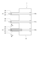
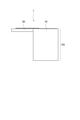
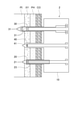
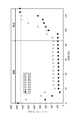
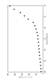
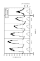
- FIG. 3 is a cross-sectional view taken along the line III-III in FIG. It is a usage state explanatory drawing of the plant water content sensor which concerns on 1st Embodiment. It is a top view of the plant water content sensor which concerns on 2nd Embodiment. It is a top view of the plant water content sensor which concerns on 3rd Embodiment. It is explanatory drawing of the tip angle ⁇ , the width W, and the thickness T of a probe. It is a graph which shows the test result of the response characteristic.
- the plant water content sensor 1 according to the first embodiment of the present invention can be attached to the details of a plant such as the shoot end of the plant and the fruit stalk.
- the plant water content sensor 1 has a function of measuring the water content in the details of the plant.
- the plant water content sensor 1 includes a support portion 10.
- the support portion 10 is provided with a water content probe 20, an electric conductivity probe 30, and a temperature probe 40. By piercing the plant with these probes 20, 30 and 40, the plant water content sensor 1 is attached to the plant.
- the water content probe 20 is used for measuring the water content of plants.
- the electric conductivity probe 30 is used for measuring the electric conductivity of water in a plant.
- the measured electrical conductivity is used to compensate for the measured water content. Therefore, when it is not necessary to compensate by the electric conductivity, it is not necessary to provide the electric conductivity probe 30 in the plant water content sensor 1.
- the temperature probe 40 is used to measure the temperature of water in a plant. The measured temperature is used to compensate for either or both of the moisture content and electrical conductivity measurements. Therefore, when it is not necessary to compensate by temperature, it is not necessary to provide the temperature probe 40 in the plant water content sensor 1.
- the base ends of the probes 20, 30 and 40 are supported by the support portion 10 in a state where they are arranged in parallel in the same plane.
- the order of the probes 20, 30, and 40 is not particularly limited. However, when both the water content measured value and the electric conductivity measured value are temperature-compensated, it is preferable to arrange the temperature probe 40 near both the water content probe 20 and the electric conductivity probe 30. That is, it is preferable to arrange the temperature probe 40 between the water content probe 20 and the electric conductivity probe 30.
- the support portion 10 and the probes 20, 30, and 40 are formed by processing a semiconductor substrate.
- the semiconductor substrate include a silicon substrate and an SOI (Silicon on Insulator) substrate.
- SOI Silicon on Insulator
- MEMS technology using thin film formation such as sputtering method and thin film deposition method is used for processing semiconductor substrates.
- the support portion 10 is a member that supports the probes 20, 30, and 40.
- the support portion 10 is a plate material having a rectangular shape in a plan view, and all the probes 20, 30, and 40 are supported on one long side portion.
- the support portion 10 may have a length in the longitudinal direction that allows all the probes 20, 30, and 40 to be arranged at predetermined intervals.
- the length of the support portion 10 in the lateral direction is not particularly limited.
- Each probe 20, 30, 40 is a rod-shaped member, and is provided in a cantilever shape on the edge (long side portion) of the support portion 10. It is preferable that the tips of the probes 20, 30 and 40 are formed in a pointed shape such as a triangle. If the tips of the probes 20, 30 and 40 are pointed, the penetration resistance when the probes 20, 30 and 40 are pierced into the details of the plant can be reduced.
- the tip angles of the probes 20, 30, and 40 are preferably 40 to 60 °.
- the punctured portion and the cells around it may be destroyed, and water in the plant may flow out.
- the measured value of the water content becomes smaller than the actual value due to the outflow of water.
- the sharper the tips of the probes 20, 30 and 40 the more the outflow of water in the plant can be suppressed.
- the tip angles of the probes 20, 30 and 40 are 60 ° or less, the tip is sufficiently sharp, so that it is possible to suppress the outflow of water in the plant when the probe is pierced. Therefore, the water content of the plant can be measured accurately.
- the tip angles of the probes 20, 30 and 40 are made too small, the widths of the probes 20, 30 and 40 become narrow and the area for mounting the element described later cannot be secured, or the length in the axial direction becomes too long. .. If the tip angle of the probes 20, 30 and 40 is 40 ° or more, the width and length of the probes 20, 30 and 40 can be made into appropriate dimensions.
- Each probe 20, 30, 40 is formed in a size that can be pierced into the details of a plant having a stem diameter or a shaft diameter of about several mm, such as the shoot end of the plant and the fruit stalk.
- the length of each probe 20, 30, 40 (the length from the base end to the tip in the axial direction) is such that the tip of each probe is attached to the vessel or phloem of the detail of the plant when it is installed by piercing the detail of the plant. It is formed in dimensions that can be placed. For example, the lengths of the probes 20, 30, and 40 are 50 to 1,500 ⁇ m.
- each probe 20, 30, 40 is not particularly limited, but is, for example, 50 to 500 ⁇ m. The narrower the probes 20, 30 and 40 are, the less damage they can do to the plant.
- each of the probes 20, 30, and 40 is formed thinner than the thickness of the support portion 10 by removing the lower portion of the semiconductor substrate SS.
- the thickness of each probe 20, 30, 40 is set to be thinner than the width of the phloem and vessel of the plant.
- the thickness of each probe 20, 30, 40 depends on the type of plant to be measured and the thickness of the stem, and is, for example, 50 to 300 ⁇ m. If the thickness is 50 ⁇ m or more, the strength is sufficient, and there is no risk of breaking when the probes 20, 30, and 40 are inserted and removed from the stem of a plant or the like.
- the thickness of the vessel and phloem is about 100 to 400 ⁇ m depending on the type of plant, if the thickness is 300 ⁇ m or less, the probes 20, 30, and 40 can be pierced into the vessel or phloem. It is possible to suppress blocking them.
- each probe 20, 30, 40 is 50 to 100 ⁇ m. The thinner the probes 20, 30 and 40, the less damage to the plant. If the thickness of each of the probes 20, 30 and 40 is 100 ⁇ m or less, the outflow of water in the plant can be suppressed and the water content of the plant can be measured accurately.
- Probes 20, 30, 40 having such a shape are formed, for example, by the following procedure. Photolithography of the probe shape is performed on the semiconductor substrate SS, and unnecessary parts are removed by dry etching such as ICP-RIE to form the original shape of the probe shape. Next, the semiconductor substrate SS is etched from the back surface so that the probes 20, 30, and 40 have a cantilever shape. In this step, dry etching such as ICP-RIE is used. The semiconductor substrate SS is etched from the back surface, and the etching is completed when the probes 20, 30, and 40 are separated. Thereby, the cantilever-shaped probes 20, 30, and 40 can be formed.
- dry etching such as ICP-RIE
- a read electrode pair 21 is provided at the tip of the water content probe 20.
- the read electrode pair 21 is composed of a pair of electrodes 22 and 22 arranged at predetermined intervals. Two electrode pads 22e and 22e connected to the two electrodes 22 via wiring are arranged on the upper surface of the support portion 10. Further, the water content probe 20 is provided with a water sensitive film 23.
- the water content probe 20 When the water content probe 20 is pierced into a plant, the water in the plant is absorbed by the water sensitive film 23. The amount of water absorbed by the water sensitive film 23 is read out as the impedance or capacitance between the electrodes 22 and 22. This makes it possible to measure the water content of the plant.
- a pair of electrodes 22 and 22 are formed on the surface of the semiconductor substrate SS constituting the water content probe 20.
- the electrode 22 is not particularly limited as long as it has a size that can be arranged at the tip of the water content probe 20.
- the electrode 22 is formed by depositing a metal thin film such as Au or Al on the semiconductor substrate SS by, for example, a sputtering method or a thin-film deposition method.
- the water sensitive film 23 is formed on a pair of electrodes 22 and 22 so as to be bridged over them.
- the water-sensitive film 23 has a function of absorbing water and is made of a material having a relative permittivity lower than that of water.
- the term "water-sensitive film” means a film formed of a material having a function of absorbing water and having a lower relative permittivity than water. Since the relative permittivity of water at a temperature of 20 ° C. is about 80, the relative permittivity of the water sensitive film 23 may be smaller than 80. However, the larger the difference between the relative permittivity of the water-sensitive film 23 and the relative permittivity of water, the higher the measurement accuracy of the water content. Therefore, the relative permittivity of the water-sensitive film 23 is preferably 1 to 3.
- the material of the water-sensitive film 23 is preferably insoluble in water and is thermally and chemically stable.
- metal oxides and ceramics include aluminum oxide (Al 2 O 3 ) and silicon dioxide (SiO 2 ). Metal oxides and ceramics are insoluble in water. However, metal oxides and ceramics are hard materials and require high-temperature heat treatment during the manufacturing process. On the other hand, polymer materials have excellent applicability to plants and are soft. Examples of the polymer material include polyimide and polyvinyl alcohol.
- polyimide is preferable from the viewpoint of ease of mounting on a semiconductor Si substrate.
- polyimide is difficult to dissolve in water, it is suitable for long-term measurement of water content in plants. Therefore, if the water-sensitive film 23 is formed of polyimide, the water-sensitive film 23 is difficult to dissolve in the water in the plant, and long-term measurement is possible.
- the surface of the water-sensitive film 23 may be hydrophilized. Then, the water in the plant is easily absorbed by the water-sensitive film 23, and the response speed of the water content measurement becomes faster.
- the surface of the water-sensitive film 23 may be treated with oxygen plasma.
- oxygen plasma When the surface of the polyimide is treated with oxygen plasma, a carbonyl group is introduced and the surface of the polyimide is hydrophilized. It also has the effect of increasing the surface area of the polyimide. Since the water-sensitive film 23 becomes hydrophilic and the surface area increases, the water in the plant is easily absorbed by the water-sensitive film 23, and the response speed of the water content measurement becomes faster.
- an electric conductivity electrode pair 31 is provided at the tip of the electric conductivity probe 30.
- the electric conductivity electrode pair 31 is composed of a pair of electrodes 32, 32 arranged at predetermined intervals.
- the electric conductivity electrode pair 31 is for measuring the electric conductivity of water (such as vascular fluid) existing between the electrodes 32 and 32.
- the electrode 32 is not particularly limited as long as it has a size that can be arranged at the tip of the electric conductivity probe 30.
- the electrode 32 is formed by depositing a metal thin film such as Au or Al on the semiconductor substrate SS by, for example, a sputtering method or a thin-film deposition method.
- Two electrode pads 32e and 32e connected to the two electrodes 32 and 32 via wiring are arranged on the upper surface of the support portion 10.
- the electrical conductivity can be measured by the AC two-electrode method. That is, an AC power supply and an ammeter are connected in series between the pair of electrode pads 32e and 32e corresponding to the pair of electrodes 32 and 32.
- An AC power supply supplies a current between the electrodes 32 and 32, and an ammeter measures the current flowing between the electrodes 32 and 32. Based on Ohm's law, the electric resistance between the electrodes 32 and 32 is calculated from the current measured by the ammeter, and the electric conductivity is obtained from the electric resistance.
- the measurement range of the electric conductivity is at least 0 to 10 mS / cm.
- the measurement range of the electric conductivity by the AC two-electrode method depends on the cell constant K of the electrode pair.
- the cell constant K is obtained by dividing the distance L between the electrodes by the surface area S of the electrodes. That is, the measurement range of the electric conductivity depends on the shape of the electrode 32.
- the shape of the electrode 32 can be selected from various shapes such as a three-dimensional electrode, a comb tooth electrode, and a planar electrode.
- a temperature sensor 41 is provided at the tip of the temperature probe 40.
- the temperature sensor 41 has a function of sensing the temperature, and is not particularly limited as long as it has a size that can be arranged at the tip of the temperature probe 40.
- a resistance temperature detector, a pn junction diode, a thermocouple, or the like can be adopted. Since the plant water content sensor 1 is expected to be used outdoors, it is preferable to use a resistance temperature detector that does not depend on light as the temperature sensor 41. Further, two electrode pads 41e and 41e connected to the temperature sensor 41 via wiring are arranged on the upper surface of the support portion 10.
- the resistance temperature detector is formed by depositing a thin metal film suitable as a resistance temperature detector such as Au on the semiconductor substrate SS by, for example, a sputtering method or a thin film deposition method.
- the electrical resistance of the resistance temperature detector increases as the temperature rises.
- a constant current source is connected between the two electrode pads 41e and 41e.
- a constant current is supplied to the resistance temperature detector with a constant current source, and the voltage is measured with a voltmeter. The temperature can be calculated from the voltage measured by the voltmeter.
- the water content probe 20, the electric conductivity probe 30, and the temperature probe 40 may be configured as separate probes, or a part or all of them may be configured as a single probe. That is, the read electrode pair 21, the water sensitive film 23, the electric conductivity electrode pair 31, and the temperature sensor 41 may all be mounted on one probe.
- the plant water content sensor 1 may be formed by a method other than the MEMS technique as long as it can be formed so as to have the above-mentioned dimensions and functions, and the material is not limited to the silicon substrate.
- the tips of the probes 20, 30 and 40 pass through the skin layer CO of the plant and reach the phloem PH. Further, when pierced deeply, the tips of the probes 20, 30, and 40 reach the vessel XY and then the pith PI.
- the electrical conductivity of water in plants largely depends on the water absorbed from the soil, that is, the duct fluid. Therefore, it is preferable to arrange the electric conductivity probe 30 and the temperature probe 40 in the vessel XY.
- the water sensitive film 23 may be formed at least in a region covering the read electrode pair 21. However, it is preferable that the water sensitive film 23 is provided from the arrangement portion of the read electrode pair 21 to the proximal end portion of the water content probe 20. Further, it is more preferable that the water sensitive film 23 is provided so as to cover a part of the upper surface of the support portion 10 from the base end portion of the water content probe 20. In this way, a part of the water sensitive film 23 is arranged outside the plant.
- the water sensitive film 23 absorbs water according to the amount of water in the plant. In order to capture the decrease in water content in the plant, it is necessary to dehydrate the water absorbed by the water sensitive film 23. If a part of the water-sensitive film 23 is arranged on the outside of the plant, dehydration is promoted from the portion exposed to the outside air. Since dehydration from the water-sensitive membrane 23 is smoothly performed, the response speed when the water content decreases is increased.
- Z 0 is the impedance [k ⁇ ] when the water sensitive film 23 does not absorb water
- B is a coefficient representing the sensitivity of the sensor.
- Z 0 and B are determined in advance by a test.
- the impedance Z between the electrodes 22 and 22 is measured. Then, based on the equation (1), the water content WC of the plant is obtained from the measured impedance value Z.
- the water content of the plant can be measured by piercing the plant with the water content probe 20 and reading the impedance or capacitance from the read electrode pair 21.
- the water content measurement value obtained by the water content probe 20 depends on the electric conductivity of the water in the plant. Therefore, it is preferable to compensate the measured water content with the electric conductivity.
- the electric conductivity of water (mainly vessel fluid) in a plant can be measured by the electric conductivity electrode pair 31 of the electric conductivity probe 30.
- the water content measurement value is compensated based on the electric conductivity measured by the electric conductivity probe 30. This makes it possible to accurately measure the water content of the plant.
- the sensor sensitivity coefficient B in the equation (1) is obtained in advance using solutions having various electric conductivitys.
- the electrical conductivity of the water in the plant is measured at the same time.
- the water content WC of the plant is obtained from the impedance Z. In this way, by obtaining the sensor sensitivity coefficient B from the measured value of electrical conductivity, the measured value of water content can be compensated.
- the inventors of the present application have obtained the finding that the sensor sensitivity coefficient B linearly depends on the electric conductivity ⁇ . Therefore, the impedance Z is measured in advance by the water content probe 20 using various solutions of electric conductivity ⁇ , the sensor sensitivity coefficient B in the equation (1) is obtained, and the electric conductivity ⁇ and the sensor sensitivity coefficient B are obtained. Fit the relationship with with a linear function. That is, the coefficients a and b are obtained from the relational expression between the electric conductivity ⁇ represented by the following equation (2) and the sensor sensitivity coefficient B.
- the impedance Z is measured by the water content probe 20 and the electric conductivity ⁇ is measured by the electric conductivity probe 30.
- the sensor sensitivity coefficient B is obtained from the measured electric conductivity value ⁇ .
- the water content WC of the plant is obtained from the impedance Z.
- the amount of water absorbed by the water sensitive film 23 and the static electricity between the electrodes 22 and 22 are similarly used by using solutions having various electric conductivitys in advance. Find the relationship with the electric capacity.
- the electrical conductivity of the water content of the plant is measured at the same time. Based on the water content-capacitance relationship corresponding to the measured electrical conductivity, the water content WC of the plant is obtained from the capacitance C.
- the electrical conductivity of water in plants is itself useful physiological information for plant production. If the tip of the electric conductivity probe 30 is arranged in the vessel XY, the electrical conductivity of the vessel fluid can be measured. Fertilizers applied to soil are decomposed by microorganisms into salts such as nitrate nitrogen. In addition, there is a positive correlation between salinity and electrical conductivity. Therefore, by measuring the electrical conductivity of the vessel fluid, the nutrients taken up by the plant can be quantified.
- the measured electrical conductivity obtained by the electrical conductivity probe 30 depends on the temperature. Generally, the measured electrical conductivity varies by 1-3% with every 1 ° C. Therefore, it is preferable to compensate the temperature of the measured electric conductivity.
- the temperature of water (mainly duct fluid) in the plant can be measured by the temperature sensor 41 of the temperature probe 40.
- the measured electric conductivity is compensated based on the temperature measured by the temperature probe 40. This makes it possible to accurately determine the electrical conductivity of water in the plant. By further compensating the water content measurement using the electric conductivity after the temperature compensation, the water content can be obtained accurately.
- the temperature compensation of the measured electric conductivity is performed by the following procedure. That is, based on the equation (3), the measured electric conductivity is converted into the electric conductivity ⁇ 25 [S / m] at the reference temperature of 25 ° C.
- ⁇ is a temperature coefficient
- T is the temperature [° C.] of the liquid to be measured
- ⁇ is the measured value of electrical conductivity [S / m].
- the temperature coefficient ⁇ is obtained from the equation (4).
- T 1 is 25 ° C. and a temperature other than T 2 [° C.]
- T 2 is a temperature other than 25 ° C. and T 1 [° C.]
- ⁇ 1 is an electric conductivity measurement value [S / m] at T 1 .
- ⁇ 2 is the measured electric conductivity [S / m] at T 2 .
- the water content measurement value measured by the water content probe 20 does not depend on the temperature.
- the measured water content may depend on the temperature.
- the measured water content may be temperature-compensated. That is, the measured value of water content is directly compensated based on the temperature measured by the temperature probe 40. This makes it possible to measure the water content with high accuracy.
- the water content of the plant can be measured non-destructively.
- tomatoes have an increased sugar content when grown under water stress.
- an index for avoiding an extreme water shortage and actual cracking due to a rapid flow of vascular fluid to the fruit can be obtained, so that an appropriate water stress can be given. In this way, it can be utilized for high quality and stable production of crops and fruit trees.
- the plant water content sensor 2 according to the second embodiment of the present invention will be described.
- the electric conductivity probe 30 is formed longer than the other probes 20 and 40. Further, a plurality of pairs of electric conductivity electrodes 31 are arranged side by side in the axial direction on the electric conductivity probe 30.
- the electric conductivity probe 30 is provided with two electric conductivity electrode pairs 31.
- the electric conductivity electrode pair 31 on the proximal end side is arranged at substantially the same position as the temperature sensor 41 of the temperature probe 40 in the direction of piercing the plant.
- the electric conductivity electrode pair 31 on the tip side is arranged at a position deeper than the temperature sensor 41 when piercing a plant.
- the vessel fluid contains salts such as nitrate nitrogen, it has the property of having higher electrical conductivity than the water contained in other parts (skin layer CO, phloem PH, medullary PI, etc.).
- skin layer CO skin layer CO, phloem PH, medullary PI, etc.
- the electric conductivity electrode pair 31 on the proximal end side is arranged in the vessel XY, the probes 20, 30, and 40 can be pierced to an appropriate amount.
- the plant water content sensor 3 has a function of measuring the vascular fluid flow rate in addition to the water content of the plant.
- the plant water content sensor 3 of the present embodiment has two temperature probes 40, a first temperature probe 40A and a second temperature probe 40B, in the plant water content sensor 1 of the first embodiment. , A temperature probe 50 with a heater is added. Since the remaining configuration is the same as that of the first embodiment, the same members are designated by the same reference numerals and the description thereof will be omitted.
- the first and second temperature probes 40A and 40B and the temperature probe 50 with a heater are used as a pair to measure the flow rate of vascular bundle liquid.
- the temperature measured by the first temperature probe 40A is also used for temperature compensation of the water content measured value and the electric conductivity measured value.
- the first and second temperature probes 40A and 40B and the temperature probe 50 with a heater are arranged in parallel with the other probes 20 and 30 in parallel, and their base ends are supported by the support portion 10.
- the first and second temperature probes 40A and 40B are provided at positions sandwiching the temperature probe 50 with a heater. Further, the first and second temperature probes 40A and 40B and the temperature probe 50 with a heater have the same shape and dimensions as the other probes 20 and 30.
- the first and second temperature probes 40A and 40B each have the same configuration as the temperature probe 40 of the first embodiment. That is, each of the first and second temperature probes 40A and 40B is provided with a temperature sensor 41 at the tip thereof. The temperature of the vascular fluid can be measured by the temperature sensor 41.
- a temperature sensor 51 is provided at the tip of the temperature probe 50 with a heater.
- the same one as the temperature sensor 41 of the temperature probe 40 can be adopted.
- Two electrode pads 51e connected to the temperature sensor 51 via wiring are arranged on the upper surface of the support portion 10. The temperature can be measured by the temperature sensor 51 in the same manner as the temperature sensor 41 of the temperature probe 40.
- the temperature probe 50 with a heater is provided with a heater 52.
- the heater 52 only needs to be able to supply heat to the temperature probe 50 with a heater, and its position is not limited to the tip portion.
- the heater 52 is not particularly limited as long as it has a size that can be arranged in the temperature probe 50 with a heater.
- a pn junction diode formed by using an oxidation diffusion furnace can be adopted as the heater 52.
- the heater 52 may be formed by forming a thin film of Pt (platinum), NiCr (nichrome), or ITO (indium tin oxide material) by a sputtering method, a vapor deposition method, or the like and processing it into a predetermined shape. ..
- a DC constant voltage source is connected between the two electrode pads 52e and 52e.
- a DC constant voltage source supplies a constant voltage in the forward direction to the heater 52, which is a pn junction diode. Heat can be generated by passing an electric current through the heater 52.
- the plant water content sensor 3 pierces and attaches all the probes 20, 30, 40A, 40B, and 50 to the plant.
- the tips of the first and second temperature probes 40A and 40B and the temperature probe 50 with a heater are arranged in the phloem PH.
- the tips of the first and second temperature probes 40A and 40B and the temperature probe 50 with a heater are arranged in the vessel XY.
- a case of measuring the flow rate of the vessel fluid will be described as an example.
- the heater 52 provided in the temperature probe 50 with a heater is operated.
- the thermal energy supplied from the heater 52 is supplied to the temperature probe 50 with a heater.
- the thermal energy supplied to the temperature probe 50 with a heater is released from the surface of the temperature probe 50 with a heater to the vessel liquid flowing in the vessel XY.
- the temperatures of the first and second temperature probes 40A and 40B and the temperature probe 50 with a heater are measured by the temperature sensors 41, 41 and 51. Then, the direction of the vessel flow is specified by comparing the temperatures of the first temperature probe 40A and the second temperature probe 40B.
- the first and second temperature probes 40A and 40B are provided at positions sandwiching the temperature probe 50 with a heater.
- the vessel fluid is heated by the temperature probe 50 with a heater. Therefore, the temperature measured by the first temperature probe 40A arranged downstream of the temperature probe 50 with a heater is higher than the temperature measured by the second temperature probe 40B arranged upstream.
- the direction of the vessel flow is from the low temperature second temperature probe 40B to the high temperature first temperature probe 40A.
- the flow rate of the vessel fluid is measured based on the Granier method from the temperatures measured by the first and second temperature probes 40A and 40B and the temperature probe 50 with a heater.
- the calculation is performed based on the temperature difference between the second temperature probe 40B, which has a lower temperature among the first and second temperature probes 40A and 40B, and the temperature probe 50 with a heater.
- the second temperature probe 40B having a lower temperature is arranged upstream of the temperature probe 50 with a heater in the vessel flow.
- the vessel fluid in the vicinity of the temperature probe 50 with a heater is always replaced with a new vessel fluid. Therefore, if the thermal energy supplied to the temperature probe 50 with a heater is constant, the temperature of the temperature probe 50 with a heater will be low.
- the flow rate of the vessel fluid is small (the flow velocity is slow)
- the vessel fluid in the vicinity of the temperature probe 50 with a heater is in a state of staying. Therefore, if the thermal energy supplied to the heater-equipped temperature probe 50 is constant, the temperature of the heater-equipped temperature probe 50 becomes high.
- the flow velocity of the vessel fluid can be obtained from the temperature difference ⁇ T between the second temperature probe 40B and the temperature probe 50 with a heater.
- the temperature difference ⁇ T is a function of the flow velocity u. Based on this function, the flow velocity u can be calculated from the temperature difference ⁇ T.
- u is the average flow velocity [m / s]
- ⁇ T (u) is the temperature difference [° C.] between the temperature probe 40B and the temperature probe 50 with a heater when the average flow velocity is u
- ⁇ T (0) is the maximum of ⁇ T.
- ⁇ and ⁇ are coefficients obtained from the observed data.
- the flow rate F can be calculated from the flow velocity u based on the equation (6).
- F is the flow rate [m 3 / s]
- S is the cross-sectional area of the vessel [m 2 ].
- the flow velocity and flow rate of the phloem liquid can be obtained together with the direction of the phloem flow. can.
- the plant water content sensor 3 can also measure the flow rate of the vascular fluid by the heat pulse method.
- the temperature probe 40 provided in the plant water content sensor 3 may be one. Even with such a configuration, the flow rate of the vascular fluid can be measured.
- the plant water content sensor 3 can measure the vascular fluid flow rate in addition to the water content of the plant. Therefore, the water dynamics of the plant can be grasped from various angles, and the state of the plant can be understood in more detail.
- Tip angle First, a test was performed on the tip angle of the probe. As shown in FIG. 7, a flat plate-shaped probe was manufactured using a silicon substrate. As shown in FIG. 7, the tip angle ⁇ , the width W, and the thickness T of the probe are defined. Four probes with tip angles ⁇ of 136 °, 120 °, 90 °, and 60 ° were manufactured. Each probe has a width W of 480 ⁇ m and a thickness T of 300 ⁇ m.
- a plant water content sensor having the configuration shown in FIG. 1 was manufactured using a silicon substrate.
- the tip angle ⁇ of each probe is 60 °
- the width W is 480 ⁇ m
- the thickness T is 300 ⁇ m
- the length is 1,200 ⁇ m.
- Various electrodes, resistance temperature detectors and wiring were made of Au.
- the water sensitive film was formed of polyimide.
- Each cotton wool was brought into contact with the water-sensitive film of the water content probe and removed after a certain period of time.
- the time change of the impedance measured by the water content probe during this period is shown in the graph of FIG.
- the measured impedance value stabilizes about 20 seconds after the cotton wool is brought into contact with the water-sensitive film.
- the measured impedance value stabilizes about 30 seconds after the cotton wool is removed from the water-sensitive film. From this, it can be seen that the response speed of the water content probe is about 30 seconds. Compared to the time scale of plant irrigation (several hours), the response speed is sufficiently fast.
- the impedance measurement value is almost constant after the cotton wool is brought into contact with the water-sensitive film and the impedance measurement value is stabilized until the cotton wool is removed. From this, it was confirmed that the water content measurement was stable. Further, the impedance after removing the cotton wool from the water-sensitive film returns to the value before the cotton wool was brought into contact with the water-sensitive film. From this, it was confirmed that the water content was sufficiently reproducible. From the above, it was confirmed that the water content probe has good response characteristics.
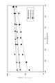
- the impedance changes exponentially with the change of the water content.
- the water content of a general plant is 98 to 60%. From the graph of FIG. 9, it was confirmed that the plant water content sensor can measure the water content in the range of 100 to 40%, which covers the range of general plant water content.
- the water content changes day and night and decreases day by day.
- the water content after watering at the start of measurement and the water content after watering after 5 days are about the same. It can be said that this change in water content reproduces the change in water content of plants that changes due to rainfall. From this, it was confirmed that the plant water content sensor can measure the water content of the plant in real time without destruction.
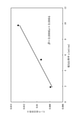
- FIG. 11 The measurement points shown in FIG. 11 were fitted by the equation (1) to obtain the sensor sensitivity coefficient B.
- FIG. 12 shows the relationship between the electric conductivity ⁇ of the KCl solution and the sensor sensitivity coefficient B. From FIG. 12, it can be seen that the electric conductivity ⁇ and the sensor sensitivity coefficient B have a linear relationship.
- the measured value of water content obtained by the water content probe can be compensated by the electric conductivity if the relational expression between the sensor sensitivity coefficient B and the electric conductivity ⁇ is obtained in advance by a test or the like. ..
Landscapes
- Chemical & Material Sciences (AREA)
- Life Sciences & Earth Sciences (AREA)
- Health & Medical Sciences (AREA)
- General Health & Medical Sciences (AREA)
- Immunology (AREA)
- Pathology (AREA)
- Analytical Chemistry (AREA)
- Biochemistry (AREA)
- Physics & Mathematics (AREA)
- General Physics & Mathematics (AREA)
- Chemical Kinetics & Catalysis (AREA)
- Electrochemistry (AREA)
- Engineering & Computer Science (AREA)
- Botany (AREA)
- Wood Science & Technology (AREA)
- Food Science & Technology (AREA)
- Medicinal Chemistry (AREA)
- Investigating Or Analyzing Materials By The Use Of Electric Means (AREA)
Abstract
Description
第2態様の植物水分含有量センサは、第1態様において、所定の間隔を空けて配置された一対の電極からなる電気伝導率電極対が設けられた電気伝導率プローブを備え、前記電気伝導率プローブは前記水分含有量プローブと平行に並んだ状態で前記支持部に支持されていることを特徴とする。
第3態様の植物水分含有量センサは、第1または第2態様において、温度センサが設けられた温度プローブを備え、前記温度プローブは前記水分含有量プローブと平行に並んだ状態で前記支持部に支持されていることを特徴とする。
第4態様の植物水分含有量センサは、第1~第3態様のいずれかにおいて、前記感水膜はポリイミドで形成されていることを特徴とする。
第5態様の植物水分含有量センサは、第1~第4態様において、前記感水膜の表面は親水化処理されていることを特徴とする。
第6態様の植物水分含有量センサは、第1~第5態様のいずれかにおいて、前記感水膜は前記読出電極対の配置部から前記水分含有量プローブの基端部にわたって設けられていることを特徴とする。
第7態様の植物水分含有量センサは、第1~第6態様のいずれかにおいて、前記水分含有量プローブの先端角度は40~60°であることを特徴とする。
第8態様の植物水分含有量センサは、第2態様において、前記電気伝導率プローブは複数の前記電気伝導率電極対を有し、複数の前記電気伝導率電極対は前記電気伝導率プローブの軸方向に並んで配置されていることを特徴とする。
第9態様の植物水分含有量センサは、第3態様において、温度センサとヒータとが設けられたヒータ付温度プローブを備え、前記ヒータ付温度プローブは前記温度プローブと平行に並んだ状態で前記支持部に支持されていることを特徴とする。
第10態様の植物水分含有量測定方法は、所定の間隔を空けて配置された一対の電極からなる読出電極対と、前記一対の電極に架け渡された感水膜とが設けられた水分含有量プローブを植物に突き刺し、前記読出電極対を構成する前記一対の電極間のインピーダンスを測定し、式(1)に基づいて、インピーダンス測定値から前記植物の水分含有量を求めることを特徴とする。

第11態様の植物水分含有量測定方法は、第10態様において、所定の間隔を空けて配置された一対の電極からなる電気伝導率電極対が設けられた電気伝導率プローブを前記植物に突き刺し、前記電気伝導率電極対を構成する前記一対の電極間の電気抵抗から電気伝導率を求め、電気伝導率測定値から式(1)中のセンサ感度係数Bを求めることを特徴とする。
第12態様の植物水分含有量測定方法は、第11態様において、式(2)に基づいて、前記電気伝導率測定値から前記センサ感度係数Bを求めることを特徴とする。

第13態様の植物水分含有量測定方法は、所定の間隔を空けて配置された一対の電極からなる読出電極対と、前記一対の電極に架け渡された感水膜とが設けられた水分含有量プローブを植物に突き刺し、前記読出電極対を構成する前記一対の電極間の静電容量を測定し、静電容量測定値から前記植物の水分含有量を求めることを特徴とする。
第14態様の植物水分含有量測定方法は、第13態様において、所定の間隔を空けて配置された一対の電極からなる電気伝導率電極対が設けられた電気伝導率プローブを前記植物に突き刺し、前記電気伝導率電極対を構成する前記一対の電極間の電気抵抗から電気伝導率を求め、前記静電容量測定値および電気伝導率測定値から前記植物の水分含有量を求めることを特徴とする。
第15態様の植物水分含有量測定方法は、第11、第12または第14態様において、温度センサが設けられた温度プローブを植物に突き刺し、前記温度センサで温度を測定し、温度測定値を用いて前記電気伝導率測定値を補償することを特徴とする。
第2態様によれば、電気伝導率プローブにより測定した植物内の水分の電気伝導率に基づき水分含有量測定値を補償することで、植物の水分含有量を精度良く測定できる。
第3態様によれば、温度プローブにより測定した植物内の水分の温度に基づき水分含有量測定値電または電気伝導率測定値を補償することで、植物の水分含有量を精度良く測定できる。
第4態様は、感水膜がポリイミドで形成されているので、感水膜が植物内の水分に溶解しにくく、長期間の測定が可能である。
第5態様によれば、感水膜の表面が親水化されているので、水分含有量測定の応答速度が速くなる。
第6態様によれば、感水膜の一部が植物の外側に配置されるので、感水膜からの脱水がスムーズに行なわれ、水分含有量が減少する際の応答速度が速くなる。
第7態様によれば、水分含有量プローブの先端部が鋭利であるので、植物に突き刺した際に、植物内の水分が流出することを抑制できる。そのため、植物の水分含有量を精度良く測定できる。
第8態様によれば、電気伝導率電極対が電気伝導率プローブの軸方向に並んで配置されているので、植物内部の電気伝導率分布が分かり、道管の位置を正確に判別できる。
第9態様によれば、植物の水分含有量に加え、維管束液流量を測定できるので、植物の水分動態を多角的に把握できる。
第10態様によれば、水分含有量プローブの読出電極対から読み出したインピーダンスから植物の水分含有量を求めることができる。
第11、第12態様のいずれにおいても、電気伝導率プローブで測定した植物内の水分の電気伝導率に基づき水分含有量測定値を補償することで、植物の水分含有量を精度良く測定できる。
第13態様によれば、水分含有量プローブの読出電極対から読み出した静電容量から植物の水分含有量を求めることができる。
第14態様によれば、電気伝導率プローブで測定した植物内の水分の電気伝導率に基づき水分含有量測定値を補償することで、植物の水分含有量を精度良く測定できる。
第15態様によれば、温度プローブで測定した植物内の水分の温度に基づき電気伝導率測定値を補償することで、植物の水分含有量を精度良く測定できる。
〔第1実施形態〕
本発明の第1実施形態に係る植物水分含有量センサ1は、植物の新梢末端、果柄など、植物の細部に取り付けることができる。植物水分含有量センサ1は植物の細部における水分含有量を測定する機能を有する。
まず、植物水分含有量センサ1の構成を説明する。
図1に示すように、植物水分含有量センサ1は支持部10を備えている。支持部10には、水分含有量プローブ20、電気伝導率プローブ30および温度プローブ40が設けられている。これらのプローブ20、30、40を植物に突き刺すことで、植物に植物水分含有量センサ1が取り付けられる。
支持部10はプローブ20、30、40を支持する部材である。支持部10は、平面視長方形の板材であり、片方の長辺部に全てのプローブ20、30、40が支持されている。支持部10はその長手方向の長さが全てのプローブ20、30、40を所定の間隔で配置できる長さを有していればよい。支持部10の短手方向の長さは特に限定されない。
各プローブ20、30、40は、棒状の部材であり、支持部10の縁(長辺部)に片持ち梁状に設けられている。各プローブ20、30、40の先端部は三角形など、尖った形に形成されているのが好ましい。プローブ20、30、40の先端部が尖った形であれば、プローブ20、30、40を植物の細部に突き刺すときの刺入抵抗を小さくできる。
図1に示すように、水分含有量プローブ20の先端部には読出電極対21が設けられている。読出電極対21は所定の間隔を空けて配置された一対の電極22、22からなる。支持部10の上面には2つの電極22に配線を介して接続された2つの電極パッド22e、22eが配設されている。また、水分含有量プローブ20には感水膜23が設けられている。
図1に示すように、電気伝導率プローブ30の先端部には電気伝導率電極対31が設けられている。電気伝導率電極対31は所定の間隔を空けて配置された一対の電極32、32からなる。電気伝導率電極対31は電極32、32間に存在する水分(維管束液など)の電気伝導率を測定するためのものである。電極32は電気伝導率プローブ30の先端部に配設できる大きさのものであれば、特に限定されない。電極32は、例えば、スパッタ法、蒸着法などにより半導体基板SS上にAu、Alなどの金属薄膜を堆積させることにより形成される。
温度プローブ40の先端部には温度センサ41が設けられている。温度センサ41は、温度を感知する機能を有しており、温度プローブ40の先端部に配設できる大きさのものであれば、特に限定されない。温度センサ41として、測温抵抗体、pn接合ダイオード、熱電対などを採用できる。植物水分含有量センサ1は屋外で使用されることが想定されるため、温度センサ41として光依存性のない測温抵抗体を用いることが好ましい。また、支持部10の上面には温度センサ41に配線を介して接続された2つの電極パッド41e、41eが配設されている。
つぎに、植物水分含有量センサ1の製造方法の一例を説明する。
まず、シリコン基板の表面をウェット酸化し、酸化膜を形成する。つぎに、酸化膜上に接着層としてCrをスパッタリングし、接着層上にAuをスパッタリングして、各種の電極、測温抵抗体および配線を形成する。つぎに、レジストを塗布して配線保護膜を形成する。つぎに、ポリイミドを塗布して感水膜23を形成する。最後にドライエッチングによりシリコン基板の不要部分を除去してプローブ20、30、40を形成する。
つぎに、植物水分含有量センサ1による水分含有量の測定方法を説明する。
まず、測定対象となる植物の新梢末端、果柄などに、植物水分含有量センサ1を取り付ける。具体的には、図4に示すように、植物水分含有量センサ1の全てのプローブ20、30、40を植物に突き刺して取り付ける。このとき、植物の道管XYおよび師管PHに沿って、プローブ20、30、40を配置する。
水分含有量プローブ20を植物に突き刺すと、植物内の水分が感水膜23に吸収される。植物内の水分量に応じて感水膜23に吸収される水分量が変化する。また、感水膜23に吸収される水分量に応じて読出電極対21を構成する電極22、22間のインピーダンスが変化する。

感水膜23に吸収される水分量が増加すると、読出電極対21を構成する電極22、22間の静電容量が増加するという関係がある。特に、感水膜23の素材を適切に選択すれば、感水膜23に吸収される水分量と電極22、22間の静電容量とは線形関係となる。この関係を予め試験により求めておく。植物の水分含有量の測定時には電極22、22間の静電容量Cを測定する。そして、静電容量と水分含有量との関係に基づいて、静電容量測定値Cから植物の水分含有量WCを求める。
水分含有量プローブ20により得られた水分含有量測定値は、植物内の水分の電気伝導率に依存する。そのため、水分含有量測定値を電気伝導率で補償することが好ましい。植物内の水分(主に道管液)の電気伝導率は電気伝導率プローブ30の電気伝導率電極対31により測定できる。電気伝導率プローブ30により測定した電気伝導率に基づき水分含有量測定値を補償する。これにより、植物の水分含有量を精度良く測定できる。

電気伝導率プローブ30により得られた電気伝導率測定値は温度に依存する。一般に、電気伝導率測定値は1℃ごとに1~3%変化する。そのため、電気伝導率測定値を温度補償することが好ましい。植物内の水分(主に道管液)の温度は温度プローブ40の温度センサ41により測定できる。温度プローブ40により測定した温度に基づき電気伝導率測定値を補償する。これにより、植物内の水分の電気伝導率を精度良く求めることができる。温度補償後の電気伝導率を用いて水分含有量測定をさらに補償することで、水分含有量を精度良く求めることができる。


つぎに、本発明の第2実施形態に係る植物水分含有量センサ2を説明する。
図5に示すように、本実施形態の植物水分含有量センサ2は、電気伝導率プローブ30が他のプローブ20、40よりも長く形成されている。また、電気伝導率プローブ30には複数の電気伝導率電極対31が軸方向に並んで配置されている。
つぎに、本発明の第3実施形態に係る植物水分含有量センサ3を説明する。植物水分含有量センサ3は、植物の水分含有量に加え、維管束液流量を測定する機能を有する。
図6に示すように、本実施形態の植物水分含有量センサ3は第1実施形態の植物水分含有量センサ1において、温度プローブ40を第1温度プローブ40Aと第2温度プローブ40Bの2つとし、ヒータ付温度プローブ50を追加したものである。その余の構成は第1実施形態と同様であるので、同一部材に同一符号を付して説明を省略する。
第1、第2温度プローブ40A、40Bは、それぞれ、第1実施形態の温度プローブ40と同様の構成を有する。すなわち、第1、第2温度プローブ40A、40Bは、それぞれ、先端部に温度センサ41が設けられている。温度センサ41により維管束液の温度を測定できる。
ヒータ付温度プローブ50の先端部には温度センサ51が設けられている。温度センサ51として温度プローブ40の温度センサ41と同様のものを採用できる。支持部10の上面には、温度センサ51に配線を介して接続された2つの電極パッド51eが配設されている。温度プローブ40の温度センサ41と同様の方法で、温度センサ51により温度を測定できる。
つぎに、植物水分含有量センサ3による維管束液流量の測定方法を説明する。


まず、プローブの先端角度について試験を行なった。
図7に示すように、シリコン基板を用いて平板状のプローブを製作した。図7に示すように、プローブの先端角度θ、幅W、厚さTを定義する。先端角度θが136°、120°、90°、60°の4つのプローブを製作した。いずれのプローブも幅Wは480μm、厚さTは300μmである。
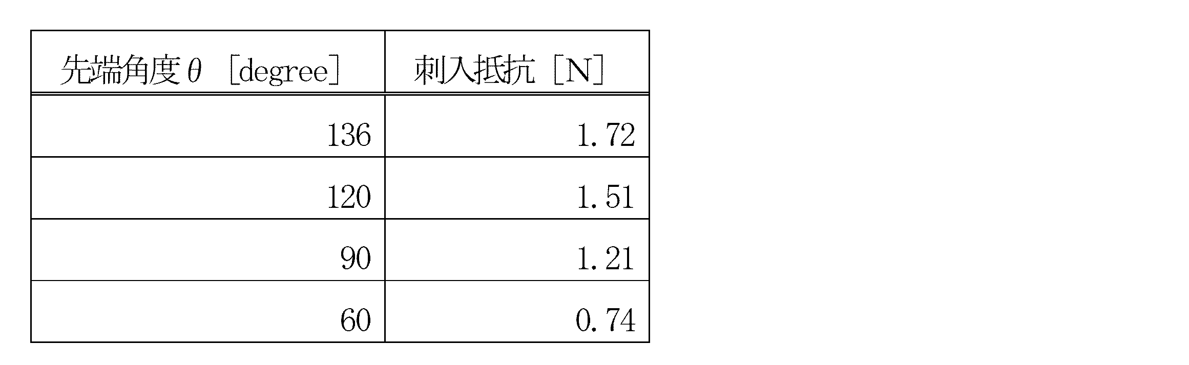
つぎに、シリコン基板を用いて図1に示す構成の植物水分含有量センサを製作した。
各プローブの先端角度θは60°、幅Wは480μm、厚さTは300μm、長さ(軸方向に基端から先端までの長さ)は1,200μmである。各種の電極、測温抵抗体および配線をAuで形成した。感水膜をポリイミドで形成した。
つぎに、製作した植物水分含有量センサの応答特性を評価した。
脱脂綿に0.05mol/LのKCl溶液を含ませ、電子天秤(AUW220D、株式会社島津製作所、以下同じ。)を用いて水分含有量を90%または60%に調整した2種類の脱脂綿を用意した。
つぎに、水分含有量測定のキャリブレーションを行なった。
電子天秤上に設置したトマト(Solanum Lycopersicum L.、以下同じ。)の切り枝に植物水分含有量センサを取り付けた。乾燥に伴う切り枝の水分含有量の時間変化を電子天秤で測定した。また、水分含有量プローブでインピーダンスの時間変化を測定した。その結果を図9に示す。また、電気伝導率プローブで切り枝内の水分の電気伝導率をしたところ4.8mS/cmであった。温度プローブで切り枝内の水分の温度をしたところ26℃であった。
つぎに、生育環境下のトマトを用いて水分含有量の測定を行なった。
培養土(420036、DCMホールディングス株式会社)に播種し、人工気象器(NC-HC、株式会社日本医化器械製作所)で生育したトマトの茎に植物水分含有量センサを取り付けた。ここで、植物水分含有量センサの取り付け位置を土壌表面から150mmの位置とした。人工気象器内の環境を温度25℃、湿度70%、二酸化炭素濃度500ppmに設定した。実時刻に合わせて人工気象器内の光量を変化させた。測定開始時と5日経過時の2回のみ500mLの水分を与える水ストレス栽培を行なった。この間に植物水分含有量センサで測定した水分含有量の時間変化を図10に示す。
つぎに、式(1)中のセンサ感度係数Bと電気伝導率σとの関係を確認した。
電気伝導率σを1.9、5.4、9.7mS/cmに調整した3種類のKCl溶液を準備した。脱脂綿にKCl溶液を含ませ、電子天秤を用いて水分含有量を測定した。また、脱脂綿を水分含有量プローブの感水膜に接触させ、インピーダンスを測定した。この操作を3種類のKCl溶液それぞれについて、脱脂綿の水分含有量を変化させつつ行なった。その結果得られた水分含有量とインピーダンスとの関係を図11に示す。
10 支持部
20 水分含有量プローブ
21 読出電極対
22 電極
23 感水膜
30 電気伝導率プローブ
31 電気伝導率電極対
32 電極
40 温度プローブ
41 温度センサ
Claims (15)
- 所定の間隔を空けて配置された一対の電極からなる読出電極対と、前記一対の電極に架け渡された感水膜とが設けられた水分含有量プローブと、
前記水分含有量プローブを支持する支持部と、を備える
ことを特徴とする植物水分含有量センサ。 - 所定の間隔を空けて配置された一対の電極からなる電気伝導率電極対が設けられた電気伝導率プローブを備え、
前記電気伝導率プローブは前記水分含有量プローブと平行に並んだ状態で前記支持部に支持されている
ことを特徴とする請求項1記載の植物水分含有量センサ。 - 温度センサが設けられた温度プローブを備え、
前記温度プローブは前記水分含有量プローブと平行に並んだ状態で前記支持部に支持されている
ことを特徴とする請求項1または2記載の植物水分含有量センサ。 - 前記感水膜はポリイミドで形成されている
ことを特徴とする請求項1~3のいずれかに記載の植物水分含有量センサ。 - 前記感水膜の表面は親水化処理されている
ことを特徴とする請求項1~4記載の植物水分含有量センサ。 - 前記感水膜は前記読出電極対の配置部から前記水分含有量プローブの基端部にわたって設けられている
ことを特徴とする請求項1~5のいずれかに記載の植物水分含有量センサ。 - 前記水分含有量プローブの先端角度は40~60°である
ことを特徴とする請求項1~6のいずれかに記載の植物水分含有量センサ。 - 前記電気伝導率プローブは複数の前記電気伝導率電極対を有し、
複数の前記電気伝導率電極対は前記電気伝導率プローブの軸方向に並んで配置されている
ことを特徴とする請求項2記載の植物水分含有量センサ。 - 温度センサとヒータとが設けられたヒータ付温度プローブを備え、
前記ヒータ付温度プローブは前記温度プローブと平行に並んだ状態で前記支持部に支持されている
ことを特徴とする請求項3記載の植物水分含有量センサ。 - 所定の間隔を空けて配置された一対の電極からなる読出電極対と、前記一対の電極に架け渡された感水膜とが設けられた水分含有量プローブを植物に突き刺し、
前記読出電極対を構成する前記一対の電極間のインピーダンスを測定し、
式(1)に基づいて、インピーダンス測定値から前記植物の水分含有量を求める
ことを特徴とする植物水分含有量測定方法。
ここで、Zはインピーダンス測定値、Z0は前記感水膜が水分を吸収していない場合のインピーダンス、Bはセンサ感度係数、WCは水分含有量である。
- 所定の間隔を空けて配置された一対の電極からなる電気伝導率電極対が設けられた電気伝導率プローブを前記植物に突き刺し、
前記電気伝導率電極対を構成する前記一対の電極間の電気抵抗から電気伝導率を求め、
電気伝導率測定値から式(1)中のセンサ感度係数Bを求める
ことを特徴とする請求項10記載の植物水分含有量測定方法。 - 式(2)に基づいて、前記電気伝導率測定値から前記センサ感度係数Bを求める
ことを特徴とする請求項11記載の植物水分含有量測定方法。
ここで、Bはセンサ感度係数、σは電気伝導率、a、bは予め定められた係数である。
- 所定の間隔を空けて配置された一対の電極からなる読出電極対と、前記一対の電極に架け渡された感水膜とが設けられた水分含有量プローブを植物に突き刺し、
前記読出電極対を構成する前記一対の電極間の静電容量を測定し、
静電容量測定値から前記植物の水分含有量を求める
ことを特徴とする植物水分含有量測定方法。 - 所定の間隔を空けて配置された一対の電極からなる電気伝導率電極対が設けられた電気伝導率プローブを前記植物に突き刺し、
前記電気伝導率電極対を構成する前記一対の電極間の電気抵抗から電気伝導率を求め、
前記静電容量測定値および電気伝導率測定値から前記植物の水分含有量を求める
ことを特徴とする請求項13記載の植物水分含有量測定方法。 - 温度センサが設けられた温度プローブを植物に突き刺し、
前記温度センサで温度を測定し、
温度測定値を用いて前記電気伝導率測定値を補償する
ことを特徴とする請求項11、12または14記載の植物水分含有量測定方法。
Priority Applications (4)
| Application Number | Priority Date | Filing Date | Title |
|---|---|---|---|
| CN202180055538.0A CN116075217A (zh) | 2020-08-18 | 2021-08-02 | 植物水分含量传感器及植物水分含量测量方法 |
| JP2022543350A JP7669049B2 (ja) | 2020-08-18 | 2021-08-02 | 植物水分含有量センサおよび植物水分含有量測定方法 |
| US18/022,127 US12517075B2 (en) | 2020-08-18 | 2021-08-02 | Plant water content sensor and plant water content measuring method |
| EP21858155.1A EP4197314B1 (en) | 2020-08-18 | 2021-08-02 | Plant water content sensor and plant water content measurement method |
Applications Claiming Priority (2)
| Application Number | Priority Date | Filing Date | Title |
|---|---|---|---|
| JP2020138022 | 2020-08-18 | ||
| JP2020-138022 | 2020-08-18 |
Publications (1)
| Publication Number | Publication Date |
|---|---|
| WO2022039007A1 true WO2022039007A1 (ja) | 2022-02-24 |
Family
ID=80322650
Family Applications (1)
| Application Number | Title | Priority Date | Filing Date |
|---|---|---|---|
| PCT/JP2021/028568 Ceased WO2022039007A1 (ja) | 2020-08-18 | 2021-08-02 | 植物水分含有量センサおよび植物水分含有量測定方法 |
Country Status (5)
| Country | Link |
|---|---|
| US (1) | US12517075B2 (ja) |
| EP (1) | EP4197314B1 (ja) |
| JP (1) | JP7669049B2 (ja) |
| CN (1) | CN116075217A (ja) |
| WO (1) | WO2022039007A1 (ja) |
Cited By (2)
| Publication number | Priority date | Publication date | Assignee | Title |
|---|---|---|---|---|
| WO2023074362A1 (ja) * | 2021-10-25 | 2023-05-04 | 国立大学法人香川大学 | 維管束液流速センサ、維管束液流速測定装置および維管束液流速測定方法 |
| EP4273543A1 (en) * | 2022-05-06 | 2023-11-08 | Global Cen Technologies, SL | System and method for the evaluation of the hydric state of a plant |
Families Citing this family (4)
| Publication number | Priority date | Publication date | Assignee | Title |
|---|---|---|---|---|
| US12135319B2 (en) * | 2019-03-28 | 2024-11-05 | David Hanson | Electrical impedance spectroscopy for non-destructive, real-time, tracking of relative water content and stress responses in plants |
| CN116908040B (zh) * | 2023-09-12 | 2023-11-24 | 北京崇光药业有限公司 | 一种具有物料检测功能的切片机 |
| WO2025254230A1 (ko) * | 2024-06-04 | 2025-12-11 | (주)텔로팜 | 식물의 수액 흐름 상태를 측정하는 마이크로 니들 프로브 및 그 제조 방법 |
| CN119901787A (zh) * | 2025-01-21 | 2025-04-29 | 浙江农林大学 | 一种非接触式木本植物木质部电导检测装置及方法 |
Citations (9)
| Publication number | Priority date | Publication date | Assignee | Title |
|---|---|---|---|---|
| JPS5116995A (en) * | 1974-07-31 | 1976-02-10 | Japan Radio Co Ltd | Koshuhanyoru gansuiryosokuteisochi |
| US5621669A (en) * | 1990-07-27 | 1997-04-15 | Bjornsson; Eyjolf S. | Moisture sensor probe and control mechanism |
| JP2010266324A (ja) * | 2009-05-14 | 2010-11-25 | Keio Gijuku | 水分量測定センサ、水分量測定装置及び水供給量制御装置 |
| US20140109658A1 (en) * | 2012-10-22 | 2014-04-24 | Carl L.C. Kah, JR. | Plant stem tree branch or trunk moisture probe |
| JP2015145810A (ja) | 2014-02-03 | 2015-08-13 | 国立大学法人 香川大学 | 植物水分動態センサ |
| CN106932447A (zh) * | 2017-03-07 | 2017-07-07 | 江苏大学 | 一种栽培基质含水量电导率的复合结构传感器及其复合修正方法 |
| CN107796854A (zh) * | 2017-09-05 | 2018-03-13 | 北京林业大学 | 一种森林土壤参数测量装置及方法 |
| KR20180038206A (ko) * | 2016-10-06 | 2018-04-16 | 경희대학교 산학협력단 | 다중채널 정전용량형 유전율 변화 감지 장치 및 그 방법과 이를 포함하는 식물 가뭄 모니터링 시스템 |
| WO2018079186A1 (ja) * | 2016-10-27 | 2018-05-03 | 国立大学法人香川大学 | 維管束液計測センサ、および維管束液計測センサの製造方法 |
Family Cites Families (21)
| Publication number | Priority date | Publication date | Assignee | Title |
|---|---|---|---|---|
| JPS62285054A (ja) | 1986-06-04 | 1987-12-10 | Toshiba Corp | 感湿素子 |
| DE69129859D1 (de) * | 1990-10-12 | 1998-08-27 | Watson | Feuchtigkeits- und salzgehaltssensor und verfahren zum gebrauch |
| JPH06273434A (ja) * | 1993-03-23 | 1994-09-30 | Kazuhiro Sugata | 流速測定装置 |
| KR100351810B1 (ko) | 1999-12-13 | 2002-09-11 | 엘지전자 주식회사 | 절대습도센서 |
| WO2006021985A1 (ja) | 2004-08-23 | 2006-03-02 | Incorporated Administrative Agency National Agriculture And Food Research Organization | 被乾燥物含水率の非破壊計測方法及び装置 |
| TWI314989B (en) * | 2006-06-23 | 2009-09-21 | Fego Prec Ind Co Ltd | Humidity sensor having temperature compensation self-comparing and manufacturing method therefore |
| JP2011027458A (ja) | 2009-07-22 | 2011-02-10 | Mitsubishi Materials Corp | 湿度センサ |
| WO2011158812A1 (ja) * | 2010-06-17 | 2011-12-22 | 国立大学法人豊橋技術科学大学 | 土壌の水分状態特定装置及びその方法 |
| US9146206B2 (en) * | 2012-02-03 | 2015-09-29 | Deere & Company | Capacitance-based moisture sensor |
| KR101495666B1 (ko) | 2013-04-18 | 2015-02-26 | 인하대학교 산학협력단 | 다공성 형태의 감습구멍을 갖는 정전용량형 습도센서 |
| JP6083745B2 (ja) | 2013-04-22 | 2017-02-22 | 国立大学法人 香川大学 | 植物水分動態センサ |
| US10161895B2 (en) * | 2014-12-23 | 2018-12-25 | 3M Innovative Properties Company | Electronic moisture sensor |
| KR20160096748A (ko) | 2015-02-05 | 2016-08-17 | 인하대학교 산학협력단 | 정전용량형 습도 센서 및 그 제조 방법 |
| JP6668599B2 (ja) | 2015-03-13 | 2020-03-18 | 株式会社村田製作所 | 水分検出用rficデバイス |
| KR101711785B1 (ko) | 2016-01-12 | 2017-03-02 | 서울대학교산학협력단 | 식물의 전기전도도 측정용 마이크로 니들 프로브 및 이를 구비한 전기전도도 측정장치 |
| WO2017123000A1 (ko) | 2016-01-12 | 2017-07-20 | 서울대학교 산학협력단 | 식물의 수액 흐름 측정용 마이크로 니들 프로브 및 이를 구비한 수액 흐름 측정 장치 |
| JP6809930B2 (ja) | 2017-02-10 | 2021-01-06 | 新日本無線株式会社 | 静電容量型湿度センサ |
| KR101807749B1 (ko) * | 2017-09-18 | 2017-12-13 | 인창전자주식회사 | 습도 센서 |
| DE102018111336B4 (de) * | 2018-05-11 | 2021-09-30 | Stenon Gmbh | Vorrichtungen und Verfahren zur In-Situ-Bodenanalyse |
| KR102054429B1 (ko) | 2019-07-22 | 2019-12-10 | (주)이레아이에스 | 배지 상태 측정 방법 및 그 장치 |
| US12130252B2 (en) * | 2019-11-04 | 2024-10-29 | Nutriprobe, Llc | Soil moisture and nutrient sensor system |
-
2021
- 2021-08-02 JP JP2022543350A patent/JP7669049B2/ja active Active
- 2021-08-02 WO PCT/JP2021/028568 patent/WO2022039007A1/ja not_active Ceased
- 2021-08-02 US US18/022,127 patent/US12517075B2/en active Active
- 2021-08-02 CN CN202180055538.0A patent/CN116075217A/zh active Pending
- 2021-08-02 EP EP21858155.1A patent/EP4197314B1/en active Active
Patent Citations (9)
| Publication number | Priority date | Publication date | Assignee | Title |
|---|---|---|---|---|
| JPS5116995A (en) * | 1974-07-31 | 1976-02-10 | Japan Radio Co Ltd | Koshuhanyoru gansuiryosokuteisochi |
| US5621669A (en) * | 1990-07-27 | 1997-04-15 | Bjornsson; Eyjolf S. | Moisture sensor probe and control mechanism |
| JP2010266324A (ja) * | 2009-05-14 | 2010-11-25 | Keio Gijuku | 水分量測定センサ、水分量測定装置及び水供給量制御装置 |
| US20140109658A1 (en) * | 2012-10-22 | 2014-04-24 | Carl L.C. Kah, JR. | Plant stem tree branch or trunk moisture probe |
| JP2015145810A (ja) | 2014-02-03 | 2015-08-13 | 国立大学法人 香川大学 | 植物水分動態センサ |
| KR20180038206A (ko) * | 2016-10-06 | 2018-04-16 | 경희대학교 산학협력단 | 다중채널 정전용량형 유전율 변화 감지 장치 및 그 방법과 이를 포함하는 식물 가뭄 모니터링 시스템 |
| WO2018079186A1 (ja) * | 2016-10-27 | 2018-05-03 | 国立大学法人香川大学 | 維管束液計測センサ、および維管束液計測センサの製造方法 |
| CN106932447A (zh) * | 2017-03-07 | 2017-07-07 | 江苏大学 | 一种栽培基质含水量电导率的复合结构传感器及其复合修正方法 |
| CN107796854A (zh) * | 2017-09-05 | 2018-03-13 | 北京林业大学 | 一种森林土壤参数测量装置及方法 |
Non-Patent Citations (2)
| Title |
|---|
| See also references of EP4197314A4 |
| TAKAHASHI, NOBUHIDE; YAMAURA, I.; YAMADA, K.: "C2-11 A relationship of electrical impedance to water status of plant", 48TH PROCEEDINGS OF THE JAPAN JOINT AUTOMATIC CONTROL CONFERENCE; NOVEMBER 25-26, 2005, vol. 48, 1 January 2005 (2005-01-01), JP, pages 499 - 500, XP009534673, DOI: 10.11511/jacc.48.0.22.0 * |
Cited By (5)
| Publication number | Priority date | Publication date | Assignee | Title |
|---|---|---|---|---|
| WO2023074362A1 (ja) * | 2021-10-25 | 2023-05-04 | 国立大学法人香川大学 | 維管束液流速センサ、維管束液流速測定装置および維管束液流速測定方法 |
| JP2023063920A (ja) * | 2021-10-25 | 2023-05-10 | 国立大学法人 香川大学 | 維管束液流速センサ、維管束液流速測定装置および維管束液流速測定方法 |
| JP7768538B2 (ja) | 2021-10-25 | 2025-11-12 | 国立大学法人 香川大学 | 維管束液流速センサ、維管束液流速測定装置および維管束液流速測定方法 |
| EP4273543A1 (en) * | 2022-05-06 | 2023-11-08 | Global Cen Technologies, SL | System and method for the evaluation of the hydric state of a plant |
| WO2023213861A1 (en) * | 2022-05-06 | 2023-11-09 | Global Cen Technologies, Sl | System and method for the evaluation of the hydric state of a plant |
Also Published As
| Publication number | Publication date |
|---|---|
| CN116075217A (zh) | 2023-05-05 |
| EP4197314A1 (en) | 2023-06-21 |
| EP4197314A4 (en) | 2024-02-28 |
| US12517075B2 (en) | 2026-01-06 |
| US20230304952A1 (en) | 2023-09-28 |
| JP7669049B2 (ja) | 2025-04-28 |
| JPWO2022039007A1 (ja) | 2022-02-24 |
| EP4197314B1 (en) | 2026-03-18 |
Similar Documents
| Publication | Publication Date | Title |
|---|---|---|
| JP7669049B2 (ja) | 植物水分含有量センサおよび植物水分含有量測定方法 | |
| Yin et al. | A field‐deployable, wearable leaf sensor for continuous monitoring of vapor‐pressure deficit | |
| EP3104135B1 (en) | Plant moisture movement state sensor | |
| EP4048058B1 (en) | Method for determining a relative change in a sap flow density in a vascular plant, software program, and measurement arrangement | |
| Jeon et al. | Development of electrical conductivity measurement technology for key plant physiological information using microneedle sensor | |
| EP2021833A1 (en) | Method and system for monitoring growth characteristics | |
| JP7539165B2 (ja) | 維管束液計測センサ | |
| US20250180532A1 (en) | Electrical impedance sptroscopy for non-destructive, real-time, tracking of relative water content and stress response in plants | |
| Hossain et al. | Tattoo-like flexible ethylene sensor for plant stress monitoring in real-time | |
| JP2010266324A (ja) | 水分量測定センサ、水分量測定装置及び水供給量制御装置 | |
| Han et al. | Continuous and real-time measurement of plant water potential using an AAO-based capacitive humidity sensor for irrigation control | |
| JP6784459B2 (ja) | 非破壊、連続、自動計測するペルチィア型熱電対サイクロメータ | |
| Khan et al. | IoT enabled plant sensing systems for small and large scale automated horticultural monitoring | |
| Nassif et al. | The role of decoupling factor on sugarcane crop water use under tropical conditions | |
| Liu et al. | Transpiration estimation of banana (Musa sp.) plants with the thermal dissipation method | |
| JP7768538B2 (ja) | 維管束液流速センサ、維管束液流速測定装置および維管束液流速測定方法 | |
| Sutton et al. | Electronic monitoring and use of microprocessors in the field | |
| Ino et al. | Microsensor device for minimally invasive measurement of moisture storage in plants shoots | |
| Ishida et al. | Microsensor Device for Simultaneously Measuring Moisture & Nutrient Substance Dynamics in Plants | |
| Eguchi et al. | Non-contact measurements of storage organ growth in fruit and root crops | |
| Schurer | TFDL-Wageningen | |
| Iwashita et al. | Needle-type in-situ plant water content sensors with polyethersulfone membrane | |
| Noguchi et al. | Abstract# 69, Honolulu PRiME 2012,© 2012 The Electrochemical Society | |
| Sangmen et al. | Flexible Temperature and Humidity Dual-sensor Suite for Real-time Monitoring of Leaf Microclimate under Water Stress Conditions |
Legal Events
| Date | Code | Title | Description |
|---|---|---|---|
| 121 | Ep: the epo has been informed by wipo that ep was designated in this application |
Ref document number: 21858155 Country of ref document: EP Kind code of ref document: A1 |
|
| DPE1 | Request for preliminary examination filed after expiration of 19th month from priority date (pct application filed from 20040101) | ||
| ENP | Entry into the national phase |
Ref document number: 2022543350 Country of ref document: JP Kind code of ref document: A |
|
| NENP | Non-entry into the national phase |
Ref country code: DE |
|
| ENP | Entry into the national phase |
Ref document number: 2021858155 Country of ref document: EP Effective date: 20230320 |
|
| WWG | Wipo information: grant in national office |
Ref document number: 18022127 Country of ref document: US |
|
| WWG | Wipo information: grant in national office |
Ref document number: 2021858155 Country of ref document: EP |