WO2022039149A1 - 水集積装置、及び水集積方法 - Google Patents
水集積装置、及び水集積方法 Download PDFInfo
- Publication number
- WO2022039149A1 WO2022039149A1 PCT/JP2021/030010 JP2021030010W WO2022039149A1 WO 2022039149 A1 WO2022039149 A1 WO 2022039149A1 JP 2021030010 W JP2021030010 W JP 2021030010W WO 2022039149 A1 WO2022039149 A1 WO 2022039149A1
- Authority
- WO
- WIPO (PCT)
- Prior art keywords
- absorbing material
- moisture absorbing
- layer
- conductive member
- heat conductive
- Prior art date
- Legal status (The legal status is an assumption and is not a legal conclusion. Google has not performed a legal analysis and makes no representation as to the accuracy of the status listed.)
- Ceased
Links
Images





Classifications
-
- B—PERFORMING OPERATIONS; TRANSPORTING
- B01—PHYSICAL OR CHEMICAL PROCESSES OR APPARATUS IN GENERAL
- B01D—SEPARATION
- B01D53/00—Separation of gases or vapours; Recovering vapours of volatile solvents from gases; Chemical or biological purification of waste gases, e.g. engine exhaust gases, smoke, fumes, flue gases, aerosols
- B01D53/26—Drying gases or vapours
- B01D53/261—Drying gases or vapours by adsorption
-
- B—PERFORMING OPERATIONS; TRANSPORTING
- B01—PHYSICAL OR CHEMICAL PROCESSES OR APPARATUS IN GENERAL
- B01J—CHEMICAL OR PHYSICAL PROCESSES, e.g. CATALYSIS OR COLLOID CHEMISTRY; THEIR RELEVANT APPARATUS
- B01J20/00—Solid sorbent compositions or filter aid compositions; Sorbents for chromatography; Processes for preparing, regenerating or reactivating thereof
- B01J20/28—Solid sorbent compositions or filter aid compositions; Sorbents for chromatography; Processes for preparing, regenerating or reactivating thereof characterised by their form or physical properties
- B01J20/28014—Solid sorbent compositions or filter aid compositions; Sorbents for chromatography; Processes for preparing, regenerating or reactivating thereof characterised by their form or physical properties characterised by their form
- B01J20/28042—Shaped bodies; Monolithic structures
-
- B—PERFORMING OPERATIONS; TRANSPORTING
- B01—PHYSICAL OR CHEMICAL PROCESSES OR APPARATUS IN GENERAL
- B01D—SEPARATION
- B01D53/00—Separation of gases or vapours; Recovering vapours of volatile solvents from gases; Chemical or biological purification of waste gases, e.g. engine exhaust gases, smoke, fumes, flue gases, aerosols
- B01D53/02—Separation of gases or vapours; Recovering vapours of volatile solvents from gases; Chemical or biological purification of waste gases, e.g. engine exhaust gases, smoke, fumes, flue gases, aerosols by adsorption, e.g. preparative gas chromatography
-
- B—PERFORMING OPERATIONS; TRANSPORTING
- B01—PHYSICAL OR CHEMICAL PROCESSES OR APPARATUS IN GENERAL
- B01D—SEPARATION
- B01D53/00—Separation of gases or vapours; Recovering vapours of volatile solvents from gases; Chemical or biological purification of waste gases, e.g. engine exhaust gases, smoke, fumes, flue gases, aerosols
- B01D53/02—Separation of gases or vapours; Recovering vapours of volatile solvents from gases; Chemical or biological purification of waste gases, e.g. engine exhaust gases, smoke, fumes, flue gases, aerosols by adsorption, e.g. preparative gas chromatography
- B01D53/04—Separation of gases or vapours; Recovering vapours of volatile solvents from gases; Chemical or biological purification of waste gases, e.g. engine exhaust gases, smoke, fumes, flue gases, aerosols by adsorption, e.g. preparative gas chromatography with stationary adsorbents
- B01D53/0407—Constructional details of adsorbing systems
- B01D53/0438—Cooling or heating systems
-
- B—PERFORMING OPERATIONS; TRANSPORTING
- B01—PHYSICAL OR CHEMICAL PROCESSES OR APPARATUS IN GENERAL
- B01D—SEPARATION
- B01D53/00—Separation of gases or vapours; Recovering vapours of volatile solvents from gases; Chemical or biological purification of waste gases, e.g. engine exhaust gases, smoke, fumes, flue gases, aerosols
- B01D53/26—Drying gases or vapours
- B01D53/28—Selection of materials for use as drying agents
-
- B—PERFORMING OPERATIONS; TRANSPORTING
- B01—PHYSICAL OR CHEMICAL PROCESSES OR APPARATUS IN GENERAL
- B01J—CHEMICAL OR PHYSICAL PROCESSES, e.g. CATALYSIS OR COLLOID CHEMISTRY; THEIR RELEVANT APPARATUS
- B01J20/00—Solid sorbent compositions or filter aid compositions; Sorbents for chromatography; Processes for preparing, regenerating or reactivating thereof
- B01J20/22—Solid sorbent compositions or filter aid compositions; Sorbents for chromatography; Processes for preparing, regenerating or reactivating thereof comprising organic material
-
- B—PERFORMING OPERATIONS; TRANSPORTING
- B01—PHYSICAL OR CHEMICAL PROCESSES OR APPARATUS IN GENERAL
- B01J—CHEMICAL OR PHYSICAL PROCESSES, e.g. CATALYSIS OR COLLOID CHEMISTRY; THEIR RELEVANT APPARATUS
- B01J20/00—Solid sorbent compositions or filter aid compositions; Sorbents for chromatography; Processes for preparing, regenerating or reactivating thereof
- B01J20/22—Solid sorbent compositions or filter aid compositions; Sorbents for chromatography; Processes for preparing, regenerating or reactivating thereof comprising organic material
- B01J20/24—Naturally occurring macromolecular compounds, e.g. humic acids or their derivatives
-
- B—PERFORMING OPERATIONS; TRANSPORTING
- B01—PHYSICAL OR CHEMICAL PROCESSES OR APPARATUS IN GENERAL
- B01J—CHEMICAL OR PHYSICAL PROCESSES, e.g. CATALYSIS OR COLLOID CHEMISTRY; THEIR RELEVANT APPARATUS
- B01J20/00—Solid sorbent compositions or filter aid compositions; Sorbents for chromatography; Processes for preparing, regenerating or reactivating thereof
- B01J20/22—Solid sorbent compositions or filter aid compositions; Sorbents for chromatography; Processes for preparing, regenerating or reactivating thereof comprising organic material
- B01J20/26—Synthetic macromolecular compounds
- B01J20/265—Synthetic macromolecular compounds modified or post-treated polymers
- B01J20/267—Cross-linked polymers
-
- B—PERFORMING OPERATIONS; TRANSPORTING
- B01—PHYSICAL OR CHEMICAL PROCESSES OR APPARATUS IN GENERAL
- B01J—CHEMICAL OR PHYSICAL PROCESSES, e.g. CATALYSIS OR COLLOID CHEMISTRY; THEIR RELEVANT APPARATUS
- B01J20/00—Solid sorbent compositions or filter aid compositions; Sorbents for chromatography; Processes for preparing, regenerating or reactivating thereof
- B01J20/28—Solid sorbent compositions or filter aid compositions; Sorbents for chromatography; Processes for preparing, regenerating or reactivating thereof characterised by their form or physical properties
- B01J20/28014—Solid sorbent compositions or filter aid compositions; Sorbents for chromatography; Processes for preparing, regenerating or reactivating thereof characterised by their form or physical properties characterised by their form
- B01J20/28033—Membrane, sheet, cloth, pad, lamellar or mat
- B01J20/28035—Membrane, sheet, cloth, pad, lamellar or mat with more than one layer, e.g. laminates, separated sheets
-
- B—PERFORMING OPERATIONS; TRANSPORTING
- B01—PHYSICAL OR CHEMICAL PROCESSES OR APPARATUS IN GENERAL
- B01J—CHEMICAL OR PHYSICAL PROCESSES, e.g. CATALYSIS OR COLLOID CHEMISTRY; THEIR RELEVANT APPARATUS
- B01J20/00—Solid sorbent compositions or filter aid compositions; Sorbents for chromatography; Processes for preparing, regenerating or reactivating thereof
- B01J20/30—Processes for preparing, regenerating, or reactivating
- B01J20/34—Regenerating or reactivating
- B01J20/3425—Regenerating or reactivating of sorbents or filter aids comprising organic materials
-
- B—PERFORMING OPERATIONS; TRANSPORTING
- B01—PHYSICAL OR CHEMICAL PROCESSES OR APPARATUS IN GENERAL
- B01J—CHEMICAL OR PHYSICAL PROCESSES, e.g. CATALYSIS OR COLLOID CHEMISTRY; THEIR RELEVANT APPARATUS
- B01J20/00—Solid sorbent compositions or filter aid compositions; Sorbents for chromatography; Processes for preparing, regenerating or reactivating thereof
- B01J20/30—Processes for preparing, regenerating, or reactivating
- B01J20/34—Regenerating or reactivating
- B01J20/3483—Regenerating or reactivating by thermal treatment not covered by groups B01J20/3441 - B01J20/3475, e.g. by heating or cooling
-
- E—FIXED CONSTRUCTIONS
- E03—WATER SUPPLY; SEWERAGE
- E03B—INSTALLATIONS OR METHODS FOR OBTAINING, COLLECTING, OR DISTRIBUTING WATER
- E03B3/00—Methods or installations for obtaining or collecting drinking water or tap water
- E03B3/28—Methods or installations for obtaining or collecting drinking water or tap water from humid air
-
- B—PERFORMING OPERATIONS; TRANSPORTING
- B01—PHYSICAL OR CHEMICAL PROCESSES OR APPARATUS IN GENERAL
- B01D—SEPARATION
- B01D2253/00—Adsorbents used in seperation treatment of gases and vapours
- B01D2253/20—Organic adsorbents
- B01D2253/202—Polymeric adsorbents
-
- B—PERFORMING OPERATIONS; TRANSPORTING
- B01—PHYSICAL OR CHEMICAL PROCESSES OR APPARATUS IN GENERAL
- B01D—SEPARATION
- B01D2257/00—Components to be removed
- B01D2257/80—Water
-
- B—PERFORMING OPERATIONS; TRANSPORTING
- B01—PHYSICAL OR CHEMICAL PROCESSES OR APPARATUS IN GENERAL
- B01D—SEPARATION
- B01D2259/00—Type of treatment
- B01D2259/40—Further details for adsorption processes and devices
- B01D2259/40083—Regeneration of adsorbents in processes other than pressure or temperature swing adsorption
- B01D2259/40088—Regeneration of adsorbents in processes other than pressure or temperature swing adsorption by heating
- B01D2259/40098—Regeneration of adsorbents in processes other than pressure or temperature swing adsorption by heating with other heating means
Definitions
- the present invention relates to a water accumulation device and a water accumulation method.
- Patent Document 1 discloses a water accumulation device.
- the water accumulation device described in Patent Document 1 includes a moisture absorption unit and a blower fan.
- the moisture absorption unit includes an element composed of a base material and a heater.
- the base material is provided with a laminated body in which a polymer hygroscopic material is laminated.
- the heater is provided so as to be in contact with the base material.
- the moisture absorption unit is rotatably supported. The region where the moisture absorption unit rotates is divided into a moisture absorption area located at the upper part of the water accumulation device and a discharge area located at the lower part of the water accumulation device.
- the moisture in the air is supplied to the polymer hygroscopic material.
- the heater is energized.
- the polymer hygroscopic material is heated by the heater, and moisture is released from the polymer hygroscopic material.
- An object of the present invention is to provide a water accumulation device capable of accumulating water with a simple configuration and a water accumulation method.
- the water accumulation device includes a moisture absorbing material and a heat conductive member.
- the hygroscopic material contains a polymer compound having a property that the degree of hydrophilicity changes depending on the temperature.
- the heat conductive member is arranged to face a part of the outer surface of the moisture absorbing material and has heat conductivity.
- the water accumulation device includes a moisture absorbing material and a light source.
- the hygroscopic material contains a polymer compound having a property that the degree of hydrophilicity changes depending on the temperature.
- the light source irradiates the moisture absorbing material with light.
- the moisture absorbing material includes a photothermal converter that converts light into heat in a portion exposed to light.
- the water accumulation device includes a moisture absorbing material and a light source.
- the hygroscopic material contains a photoresponsive polymer compound having a property of changing the degree of hydrophilicity by light.
- the light source irradiates the moisture absorbing material with light.
- a moisture absorbing material is used in the water accumulation method.
- the hygroscopic material contains a polymer compound having a property that the degree of hydrophilicity changes depending on the temperature.
- the water accumulation method includes a step of arranging a heat conductive member facing a part of the outer surface of the moisture absorbing material.
- the water accumulation method includes a step of allowing the hygroscopic material to absorb water.
- the water accumulation method includes a step of reducing the degree of hydrophilicity of the polymer compound by heating the heat conductive member.
- the water accumulation method includes a step of releasing water from the hygroscopic material.
- water can be accumulated with a simple structure.
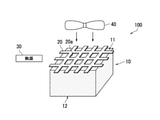
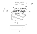
- FIG. 1 is a schematic view of the water accumulation device 100 according to the first embodiment of the present invention.
- the water accumulation device 100 is a device for accumulating water.
- the water accumulation device 100 includes a moisture absorbing material 10, a heat conductive member 20, a heat source 30, and a blower unit 40.
- the hygroscopic material 10 reversibly absorbs moisture (water vapor) in the air and releases the absorbed moisture.
- the hygroscopic material 10 contains a predetermined polymer compound having a property that the degree of hydrophilicity changes depending on the temperature (heat).
- Predetermined polymer compounds include temperature-responsive polymers whose affinity with water changes reversibly in response to heat.
- the temperature-responsive polymer is a polymer having a phase transition temperature (Lower Critical Solution Temperature; LCST).
- the temperature-responsive polymer becomes hydrophobic above the phase transition temperature.
- Temperature-responsive polymers are hydrophilic at low temperatures below the phase transition temperature.
- the temperature-responsive polymer is a polymer that dissolves in water at a low temperature lower than the phase transition temperature, but becomes hydrophobic and insolubilizes when the temperature exceeds the phase transition temperature.
- the temperature-responsive polymer is more preferably porous, but it does not necessarily have to be porous.
- the temperature-responsive polymer examples include poly (N-isopropyl (meth) acrylamide), poly (N-normal propyl (meth) acrylamide), poly (N-methyl (meth) acrylamide), and poly (N-ethyl (N-ethyl).
- Poly (N-alkyl (meth) acrylamide) such as poly (N-normal butyl (meth) acrylamide), poly (N-isobutyl (meth) acrylamide), poly (Nt-butyl (meth) acrylamide), etc.
- N-vinylalkylamide poly (N-vinylpyrrolidone); poly (2-ethyl-2-oxazoline), poly (2-isopropyl-2-oxazoline), poly (2-normalpropyl-2) -Poly (2-alkyl-2-oxazoline) such as (oxazoline); polyvinylalkyl ether such as polyvinylmethyl ether and polyvinylethyl ether; copolymer of polyethylene oxide and polypropylene oxide; poly (oxyethylene vinyl ether); methylcellulose, ethylcellulose, Examples thereof include cellulose derivatives such as hydroxypropyl cellulose and hydroxypropyl methyl cellulose, and copolymers of these polymers.
- the temperature-responsive polymer may be a crosslinked product of these polymers.
- such cross-linked product includes, for example, N-isopropyl (meth) acrylamide, N-normal propyl (meth) acrylamide, N-methyl (meth) acrylamide, and N-ethyl (meth).
- N-alkyl (meth) acrylamide such as acrylamide, N-normal butyl (meth) acrylamide, N-isobutyl (meth) acrylamide, Nt-butyl (meth) acrylamide; N-vinylisopropylamide, N-vinylnormalpropyl N-vinylalkylamides such as amides, N-vinylnormalbutylamides, N-vinylisobutylamides and N-vinyl-t-butylamides; vinylalkyl ethers such as vinylmethyl ethers and vinyl ethyl ethers; ethylene oxide and propylene oxide; 2 Monomers such as 2-alkyl-2-oxazoline such as -ethyl-2-oxazoline, 2-isopropyl-2-oxazoline, 2-normalpropyl-2-oxazoline or two or more of these monomers in the presence of a cross-linking agent. Examples thereof include a polymer obtained
- cross-linking agent conventionally known ones may be appropriately selected and used, and for example, ethylene glycol di (meth) acrylate, propylene glycol di (meth) acrylate, N, N'-methylenebis (meth) acrylamide, and tolylene.
- Crosslinkable monomers with polymerizable functional groups such as isocyanate, divinylbenzene, polyethylene glycol di (meth) acrylate; glutaaldehyde; polyhydric alcohols; polyhydric amines; polyvalent carboxylic acids; metal ions such as calcium ions and zinc ions. Etc. can be preferably used.
- These cross-linking agents may be used alone or in combination of two or more.
- the moisture absorbing material 10 has a first state and a second state.
- the first state is a state in which the hygroscopic material 10 can absorb water by improving the affinity between the predetermined polymer compound contained in the hygroscopic material 10 and water (the degree of hydrophilicity is improved). ..
- the second state is a state in which the hygroscopic material 10 releases water by reducing the affinity between the predetermined polymer compound contained in the hygroscopic material 10 and water (the degree of hydrophilicity is reduced). The hygroscopic material 10 in the second state shrinks and it becomes difficult to retain water.
- the moisture absorbing material 10 When the temperature of the moisture absorbing material 10 is lower than the phase transition temperature (for example, about 40 ° C.), the moisture absorbing material 10 is in the first state, and when the temperature of the moisture absorbing material 10 is equal to or higher than the phase transition temperature, the moisture absorbing material 10 is in the second state. It becomes a state.
- the phase transition temperature for example, about 40 ° C.
- the hygroscopic material 10 is in the first state at room temperature (the temperature of the atmosphere is a standard temperature), and is heated from this state to the second state. It is composed.
- the moisture absorbing material 10 when the moisture absorbing material 10 changes from the first state to the second state (phase transition), the moisture absorbing material 10 is heated to a predetermined heating temperature.
- the predetermined heating temperature is a temperature at which the state of the hygroscopic material 10 is maintained in the second state, and most of the water contained in the hygroscopic material 10 does not become water vapor in a short time, and the state of the liquid is maintained (for example). , 40 ° C or higher and lower than 80 ° C). As a result, the water contained in the hygroscopic material 10 is released from the hygroscopic material 10 in a liquid state.
- the moisture absorbing material 10 is formed in a substantially prismatic shape.
- the outer surface of the moisture absorbing material 10 includes a first surface 11, a second surface 12, a third surface 13, a fourth surface 14, a fifth surface 15, and a sixth surface 16.
- the first surface 11 constitutes the ceiling surface of the moisture absorbing material 10.
- the second surface 12 constitutes the bottom surface of the moisture absorbing material 10 and faces the first surface 11.
- the third surface 13 to the sixth surface 16 are located between the first surface 11 and the second surface 12.
- the third surface 13 and the fifth surface 15 form the side surfaces of the moisture absorbing material 10 and face each other.
- the fourth surface 14 constitutes the front surface of the moisture absorbing material 10, and the sixth surface 16 constitutes the rear surface of the moisture absorbing material 10.
- the fourth surface 14 and the sixth surface 16 face each other.
- the shape of the moisture absorbing material 10 is not particularly limited.
- the heat conductive member 20 has heat conductivity.
- the heat conductive member 20 is formed of, for example, metal.
- the heat conductive member 20 is formed in a mesh shape.
- the heat conductive member 20 includes a through hole 20a penetrating the heat conductive member 20.
- the heat conductive member 20 is arranged to face a part of the outer surface of the moisture absorbing material 10.
- the facing arrangement means that the heat conductive member 20 is not only in contact with a part of the outer surface of the moisture absorbing material 10, but also the heat conducting member 20 is arranged at a predetermined distance from a part of the outer surface of the moisture absorbing material 10. It is also included if it is.
- the predetermined interval is such that the heat generated from the heat conductive member 20 is transferred to the moisture absorbing material 10.
- the heat conductive member 20 is not arranged to face the other part of the outer surface of the moisture absorbing material 10, but is arranged so as to open the other part of the outer surface of the moisture absorbing material 10.
- the heat conductive member 20 is arranged to face the first surface 11 of the moisture absorbing material 10. Further, in the first embodiment, on the outer surface of the moisture absorbing material 10, the first surface 11 which is a surface (a part of the outer surface) on which the heat conductive member 20 is arranged to face each other is opened by not arranging the heat conductive member 20 to face each other.
- the heat source 30 heats the heat conductive member 20.
- the heat source 30 includes, for example, a heater.
- the configuration of the heat source 30 is not particularly limited.
- the heat source 30 may heat the heat conductive member 20 by passing an electric current through the heat conductive member 20 without using a heater.
- the blower unit 40 blows the moisture absorbing material 10.
- the blower unit 40 includes, for example, a blower fan and a power source (for example, a motor) for rotating the blower fan.
- the blower fan of the blower portion 40 is arranged to face the heat conductive member 20, and is configured to blow air to the moisture absorbing material 10 through the through hole 20a of the heat conductive member 20.
- a heater which is a heat source 30, is arranged between the blower unit 40 (blower fan) and the heat conductive member 20, so that the air from the blower unit 40 flows in the order of the heater, the heat conductive member 20, and the moisture absorbing material 10. It may be configured as.
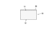
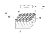
- FIGS. 2A to 4B are schematic views showing the operation of the water accumulation device 100.
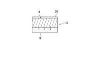
- 2B to 4B are schematic views showing the operation of the moisture absorbing material 10.
- the moisture absorbing material 10 in the first state is represented by dot hatching
- the moisture absorbing material 10 in the second state is represented by diagonal lines.
- the moisture absorbing material 10 is in the first state before the heat source 30 heats the heat conductive member 20. That is, the hygroscopic material 10 is in a state of being highly hydrophilic and easily absorbing moisture.
- the moisture absorbing material 10 is in the first state, wind is blown to the moisture absorbing material 10 by the blower unit 40. As a result, the moisture in the air can be effectively absorbed by the hygroscopic material 10.
- the heat conductive member 20 is heated by the heat source 30 when the hygroscopic material 10 is in the first state containing water.
- the heat conductive member 20 is heated, the heat of the heat conductive member 20 is transferred to the moisture absorbing material 10.
- the heat conductive member 20 heats the moisture absorbing material 10 to a predetermined heating temperature (for example, 40 ° C. or higher and lower than 80 ° C.).
- a predetermined heating temperature for example, 40 ° C. or higher and lower than 80 ° C.
- the heat from the heat conductive member 20 is transferred from the first surface 11 of the moisture absorbing material 10 (the surface of the moisture absorbing material 10 facing the heat conductive member 20) to the second surface 12 (the heat conductive member 20 of the moisture absorbing material 10). It is gradually transmitted toward the surface on the side that does not face).
- the temperature of the first surface 11 side of the moisture absorbing material 10 is raised to a predetermined heating temperature.
- the region of the moisture absorbing material 10 whose temperature has been raised to a predetermined heating temperature gradually increases from the first surface 11 side to the second surface 12 side.
- the moisture absorbing material 10 gradually changes from the first state to the second state from the first surface 11 side to the second surface 12 side.
- the hygroscopic material 10 gradually changes from a state of high hydrophilicity to a state of low hydrophilicity from the first surface 11 side to the second surface 12 side. Further, the moisture absorbing material 10 shrinks when it changes from the first state to the second state. As a result, in the moisture absorbing material 10, the first surface 11 side becomes a skin layer (wall) that prevents the movement of water, and the area of the skin layer gradually expands toward the second surface 12 side. Moisture existing on the 1st surface 11 side also moves to the 2nd surface 12 side.
- the region of the moisture absorbing material 10 in the second state expands to the second surface 12 side. I will do it. That is, the region having low hydrophilicity expands to the second surface 12 side.
- the water contained in the hygroscopic material 10 is repelled to the second surface 12 side of the hygroscopic material 10, and after the accumulation of water progresses, it exudes as water droplets from the second surface 12 and the second surface 12 Is released so as to be squeezed out from the moisture absorbing material 10.
- the moisture X released from the second surface 12 of the hygroscopic material 10 is housed in, for example, a container Y arranged below the second surface 12.
- the heat conductive member 20 is arranged to face a part of the outer surface (first surface 11) of the moisture absorbing material 10.
- the hygroscopic material 10 can be heated from the first surface 11 side and moisture can be released from the second surface 12 (see FIGS. 4A and 4B).
- moisture can be released from the moisture absorbing material 10 in a state where the positions of the moisture absorbing material 10 and the heat conductive member 20 are fixed without moving each of the moisture absorbing material 10 and the heat conductive member 20.
- the device configuration of the water accumulation device 100 can be simplified, water can be accumulated with a simple configuration.
- the moisture absorbing material 10 in the first state absorbs the moisture in the air
- the air from the blower portion 40 can be applied to the moisture absorbing material 10 through the heat conductive member 20 through the through hole 20a.
- the heat conductive member 20 and the blower unit 40 can be installed on the same side of the moisture absorbing material 10, the water accumulation device 100 can be compactly configured.
- the moisture absorbing material 10 can undergo a phase transition at a heating temperature of 40 ° C. or higher and lower than 80 ° C. Therefore, the water absorbed by the hygroscopic material 10 can be released from the hygroscopic material 10 at a temperature lower than that of zeolite, silica gel, or the like. For example, in order to release the water absorbed by the zeolite from the zeolite, a temperature of 200 ° C. or higher is required.
- the material of the heat conductive member 20 is not particularly limited as long as it is a material having high heat conductivity.
- the heat conductive member 20 may be formed of a highly heat conductive resin.
- the direction of the surface (second surface 12) for discharging water is downward, but the change from the first state to the second state of the moisture absorbing material 10 is the driving force for water release.
- the direction of the surface that discharges water (second surface 12) is not limited to downward. That is, the direction of the surface that discharges water (second surface 12) is not limited to the direction of gravity.
- the direction of the surface (second surface 12) that discharges water may be upward or sideways.
- the orientation of the surface that discharges water (second surface 12) is downward or sideways.
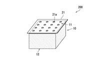
- FIG. 5 is a schematic view of the water accumulation device 200 according to the second embodiment of the present invention.
- the water accumulation device 200 includes a moisture absorbing material 10, a heat conductive member 21, a heat source 30 (not shown), and a blower unit 40 (not shown).
- the heat conductive member 21 is a first modification of the heat conductive member 20 (see FIG. 1) of the first embodiment.
- the heat conductive member 21 has a plurality of through holes 21a penetrating the heat conductive member 21.
- the heat conductive member 21 has heat conductivity and is formed of, for example, a metal.
- the heat conductive member 21 is manufactured, for example, by forming a plurality of through holes 21a in a plate-shaped base material.
- the heat conductive member 21 is, for example, a punching metal.
- the heat conductive member 21 is arranged to face a part of the outer surface (first surface 11) of the moisture absorbing material 10.
- the shape of the through hole 21a (shape when viewed in a plan view) is not particularly limited.
- the shape of the through hole 21a can be, for example, circular, elliptical, oblong, or linear. Alternatively, the shape of the through hole 21a may be a polygon, or may be a complicated shape such as
- the wind from the blower portion 40 is applied to the moisture absorbing material 10 through the through hole 21a.
- the hygroscopic material 10 in the first state can effectively absorb the moisture in the air.
- the heat conductive member 21 is heated by the heat source 30 in a state where the hygroscopic material 10 in the first state contains water. At this time, the moisture absorbing material 10 gradually raises the temperature from the first surface 11 side to the second surface 12 side to a predetermined heating temperature. As a result, in the hygroscopic material 10, the moisture existing on the first surface 11 side of the hygroscopic material 10 moves to the second surface 12 side and is discharged from the second surface 12 to the outside of the hygroscopic material 10. (See FIGS. 4A and 4B).
- the material of the heat conductive member 21 is not particularly limited as long as it is a material having high heat conductivity.
- the heat conductive member 21 may be formed of a highly heat conductive resin.
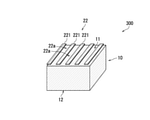
- FIG. 6 is a schematic view of the water accumulation device 300 according to the third embodiment of the present invention.
- the water accumulation device 300 includes a moisture absorbing material 10, a heat conductive member 22, a heat source 30 (not shown), and a blower unit 40 (not shown).
- the heat conductive member 22 is a second modification of the heat conductive member 20 (see FIG. 1) of the first embodiment.
- the heat conductive member 22 has heat conductivity and is formed of, for example, a metal.
- the heat conductive member 22 includes a plurality of metal plates 221.
- the plurality of metal plates 221 are arranged in parallel with a space of 22a from each other, and are arranged to face a part of the outer surface (first surface 11) of the moisture absorbing material 10.
- the wind from the blower portion 40 is applied to the moisture absorbing material 10 through the interval 22a portion of the plurality of metal plates 221.
- the hygroscopic material 10 in the first state can effectively absorb the moisture in the air.
- the heat conductive member 22 (plurality of metal plates 221) is heated by the heat source 30 in a state where the hygroscopic material 10 in the first state contains water. As a result, the moisture contained in the hygroscopic material 10 is released from the second surface 12 to the outside of the hygroscopic material 10 (see FIGS. 4A and 4B).
- the material of the heat conductive member 22 is not particularly limited as long as it is a material having high heat conductivity.
- the heat conductive member 22 may be formed of a highly heat conductive resin.
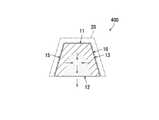
- FIG. 7A is a schematic view of the water accumulation device 400 according to the fourth embodiment of the present invention.
- the water accumulation device 400 includes a moisture absorbing material 10, a heat conductive member 20 (see FIG. 1), a heat source 30 (not shown), and a blower unit 40 (not shown).
- the heat conductive member 20 is arranged to face the first surface 11 and the third surface 13 to the sixth surface 16 of the first surface 11 to the sixth surface 16 (see FIG. 1) of the outer surface of the moisture absorbing material 10. .. That is, the heat conductive member 20 faces the outer surface of the moisture absorbing material 10 other than the second surface 12.
- the heat absorbing material 10 When the heat conductive member 20 is heated by the heat source 30, the heat absorbing material 10 is heated from the first surface 11 side and each surface side of the third surface 13 to the sixth surface 16 toward the inside of the moisture absorbing material 10. , The state of the moisture absorbing material 10 gradually changes from the first state to the second state. As a result, the water contained in the hygroscopic material 10 moves to the inside of the hygroscopic material 10, and the water is accumulated from the center to the lower part of the hygroscopic material 10, and the uneven distribution of the water in the hygroscopic material 10 progresses. After that, the accumulation of water in the central portion of the second surface 12 progresses, and as a result, water is discharged from the second surface 12 to the outside of the hygroscopic material 10.
- the heat conductive member 21 (see FIG. 5) or the heat conductive member 22 (see FIG. 6) may be used instead of the heat conductive member 20.
- the direction of the second surface 12 is downward (direction of gravity), but as described in the first embodiment, the direction of the second surface 12 is not limited to downward (direction of gravity).
- FIG. 7B is a schematic view showing a modified example of the water accumulation device 400 according to the fourth embodiment of the present invention.
- the moisture absorbing material 10 may be formed in a frustum shape such as a frustum or a quadrangular frustum.
- the ability to recover the moisture-absorbed water can be enhanced.
- the moisture-absorbing material 10 has a frustum shape
- the region closer to the second surface 12 of the moisture-absorbing material 10 is closer to the center of the moisture-absorbing material 10 than when the moisture-absorbing material 10 has a prismatic shape. Heat transfer slows down.
- the change (hydrophobicization) of the central portion of the second surface 12 to the second state is slower than that of the other portions, and the hydrophilicity is maintained until the end. Therefore, the water moves from the other portion to the central portion of the second surface 12, and the moisture collects in the central portion of the second surface 12.
- the central portion of the second surface 12 functions as a headrace and promotes the discharge of water to the outside of the moisture absorbing material 10.
- the moisture absorbing material 10 When the moisture absorbing material 10 has a frustum shape, the amount of water discharged when water is discharged from the second surface 12 to the outside of the moisture absorbing material 10 can be adjusted by adjusting the spreading of the frustum. .. In other words, the moisture absorbing material 10 can function as a faucet.
- FIG. 8 is a schematic view of the water accumulation device 500 according to the fifth embodiment of the present invention.
- the water accumulation device 500 includes a moisture absorbing material 10, a heat conductive member 20 (see FIG. 1), a heat source 30 (not shown), and a blower unit 40 (not shown).
- the heat conductive member 20 is arranged to face the first surface 11 of the moisture absorbing material 10 and the third surface 13 to the sixth surface 16.
- the first surface 11 and the third surface 13 to the sixth surface 16 are examples of facing surfaces of the present invention.
- the second surface 12 is an example of a non-opposing surface of the present invention.
- the moisture absorbing material 10 has a plurality of layers.
- the plurality of layers are laminated from the first surface 11 side to the second surface 12 side.
- the moisture absorbing material 10 has a first layer 10A, a second layer 10B, and a third layer 10C.
- the first layer 10A to the third layer 10C are laminated in the order of the first layer 10A, the second layer 10B, and the third layer 10C from the first surface 11 side to the second surface 12 side of the moisture absorbing material 10. There is.
- the first surface 11 is formed on the first layer 10A.
- the second surface 12 is formed on the third layer 10C.
- the third layer 10C is arranged closer to the second surface 12 (non-opposing surface) than the first layer 10A.
- the first layer 10A is an example of the first layer of the present invention.
- the third layer 10C is an example of the second layer of the present invention.
- the temperature (phase transition temperature) at which the first layer 10A, the second layer 10B, and the third layer 10C change from the first state to the second state increases in this order. .. That is, the lower the moisture absorbing material 10, the higher the phase transition temperature. Therefore, the hydrophilicity becomes higher in the order of the first layer 10A, the second layer 10B, and the third layer 10C, and it becomes easier to absorb water.
- the phase transition temperature of the first layer 10A is 40 ° C.
- the phase transition temperature of the second layer 10B is 45 ° C.
- the phase transition temperature of the third layer 10C is 50 ° C.
- the lower limit of the temperature (phase transition temperature) at which the temperature changes from the first state to the second state is an example of the temperature at which the degree of hydrophilicity of the polymer compound becomes lower than a predetermined reference in the present invention.
- the moisture absorbing material 10 When the moisture absorbing material 10 is porous, it is desirable that the total surface area of all the pores decreases in the order of the first layer 10A, the second layer 10B, and the third layer 10C. Specifically, in the first layer 10A to the third layer 10C, the hole size may be reduced in the order of the first layer 10A, the second layer 10B, and the third layer 10C. In the first layer 10A to the third layer 10C, it is more desirable that the number of holes is reduced and the size of the holes is reduced in the order of the first layer 10A, the second layer 10B, and the third layer 10C. ..
- phase transition temperature The higher the temperature (phase transition temperature) at which the moisture absorbing material 10 changes from the first state to the second state, the higher the hydrophilicity and the easier it is to absorb water. Therefore, when heat is transferred, water is released first from the layer with the lower phase transition temperature, and water flows from the layer with the lower phase transition temperature to the adjacent layer (the layer with the higher phase transition temperature and higher hydrophilicity). Moving. For example, water moves from the first layer 10A to the second layer 10B. Therefore, the difference in the phase transition temperature or the gradient of the phase transition temperature can strongly promote the movement of water due to heat transfer and prevent the backflow of water.
- the hygroscopic material 10 when the hygroscopic material 10 is porous, the larger the surface area (the total surface area of all the holes), the more advantageous for moisture absorption. On the other hand, the smaller the surface area, the smaller the evaporation loss. Therefore, the smaller the surface area of the hygroscopic material 10, the easier it is to release water as liquid water when the second state is reached. Therefore, by reducing the surface area of the first layer 10A, the second layer 10B, and the third layer 10C in this order, the hygroscopic material 10 is heated to a predetermined heating temperature to release water from the hygroscopic material 10. The water contained in 10 can be effectively transferred from the first layer 10A to the third layer 10C through the second layer 10B as liquid water. As a result, the water collected in the third layer 10C can be effectively discharged as liquid water from the second surface 12 of the third layer 10C to the outside of the hygroscopic material 10 (see FIGS. 4A and 4B). ).
- the temperature for heating the heat conductive member 20 may be gradually increased from a temperature near the phase transition temperature of the first layer 10A to a temperature equal to or higher than the phase transition temperature of the third layer 10C. This makes it possible to reduce the water content (evaporation loss) that evaporates from the hygroscopic material 10 and cannot be accumulated and is lost. In other words, the efficiency of collecting liquid water can be further improved.
- the speed at which the temperature for heating the heat conductive member 20 is increased is determined by the thickness of the moisture absorbing material 10, the composition of the moisture absorbing material 10, the number of holes, the ratio of the volume occupied by the holes to the volume occupied by the bulk portion, and the like.
- the heat conductive member 20 is configured to be arranged not to face the third surface 13 to the sixth surface 16 but to face only the first surface 11 as shown in FIG. You may.
- the heat conductive member 21 (see FIG. 5) or the heat conductive member 22 (see FIG. 6) may be used instead of the heat conductive member 20.
- the moisture absorbing material 10 may have a frustum shape. By forming the moisture absorbing material 10 into a frustum shape, the ability to recover the moisture-absorbed water can be enhanced.
- the moisture absorbing material 10 has three layers (first layer 10A to third layer 10C), but the moisture absorbing material 10 may have two layers and four or more layers. May have.
- the moisture absorbing material 10 has a plurality of layers, but the moisture absorbing material 10 may be configured such that the phase transition temperature gradually changes from the first surface 11 to the second surface 12. ..
- the hydrophilicity changes as the phase transition temperature changes.
- the moisture absorbing material 10 may be configured so that the phase transition temperature becomes higher as the portion closer to the second surface 12 is.
- this configuration by controlling the degree of change in the phase transition temperature from the first surface 11 to the second surface 12, water movement and water accumulation are promoted, and water is released from the second surface 12 per unit time. It is possible to control the amount of water to be discharged and the rate at which water is released from the second surface 12. Further, also in this configuration, by gradually increasing the temperature for heating the heat conductive member 20, the evaporation loss can be reduced and the collection efficiency of liquid water can be further improved.
- the moisture absorbing material 10 when the moisture absorbing material 10 is porous, the moisture absorbing material 10 may be configured so that the surface area becomes smaller as the portion closer to the second surface 12. According to this configuration, by controlling the degree of change in the surface area from the first surface 11 to the second surface 12, it becomes easier to absorb water from the first surface 11 and liquid water is discharged from the second surface 12. It can be made easy to make. In addition, the amount of water released from the second surface 12 per unit time and the rate at which water is released from the second surface 12 can be controlled.
- FIG. 9 is a schematic view of the water accumulation device 600 according to the sixth embodiment of the present invention.
- the water accumulation device 600 includes a moisture absorbing material 10, a heat conductive member 20 (see FIG. 1), a heat source 30 (not shown), and a blower unit 40 (not shown).
- the heat conductive member 20 is arranged to face the first surface 11 of the moisture absorbing material 10 and the third surface 13 to the sixth surface 16.
- the first surface 11 and the third surface 13 to the sixth surface 16 may be collectively referred to as facing surfaces.
- the moisture absorbing material 10 has a plurality of layers.
- the moisture absorbing material 10 has a fourth layer 10D, a fifth layer 10E, and a sixth layer 10F.
- the 4th layer 10D is located on the outermost side
- the 5th layer 10E is located inside the 4th layer 10D
- the 5th layer 10E is located inside the 5th layer 10E.
- the 6th layer 10F is located.
- the fourth layer 10D is formed with facing surfaces (first surface 11 and third surface 13 to sixth surface 16) facing the heat conductive member 20.
- the second surface 12 is formed on the sixth layer 10F.
- the sixth layer 10F is arranged at a place farther from the facing surfaces (first surface 11 and third surface 13 to sixth surface 16) than the fourth layer 10D.
- the fourth layer 10D is an example of the first layer of the present invention.
- the sixth layer 10F is an example of the second layer of the present invention.
- the phase transition temperature increases in the order of the 4th layer 10D, the 5th layer 10E, and the 6th layer 10F. Therefore, the inner side of the moisture absorbing material 10 has a higher phase transition temperature.
- the hygroscopic material 10 is heated to a predetermined heating temperature to release water from the hygroscopic material 10
- the water contained in the hygroscopic material 10 is treated as liquid water through the fourth layer 10D to the fifth layer 10E. It can be effectively moved to the 6th layer 10F.
- the water collected in the 6th layer 10F (the most hydrophilic layer) can be effectively released as liquid water from the second surface 12 of the 6th layer 10F to the outside of the moisture absorbing material 10. Yes (see FIGS. 4A and 4B).
- the surface area (total surface area of all holes) is increased from the innermost sixth layer 10F toward the outermost fourth layer 10D to absorb moisture. The rate is improved, and the hygroscopic capacity and the dehydration capacity of the hygroscopic material 10 can be optimized.
- the temperature for heating the heat conductive member 20 may be gradually increased from a temperature near the phase transition temperature of the fourth layer 10D to a temperature equal to or higher than the phase transition temperature of the sixth layer 10F. As a result, the evaporation loss can be reduced and the collection efficiency of liquid water can be further improved.
- the heat conductive member 21 (see FIG. 5) or the heat conductive member 22 (see FIG. 6) may be used instead of the heat conductive member 20.
- the moisture absorbing material 10 may have a frustum shape. By forming the moisture absorbing material 10 into a frustum shape, the ability to recover the moisture-absorbed water can be enhanced.
- the moisture absorbing material 10 has three layers (fourth layer 10D to the sixth layer 10F), but the moisture absorbing material 10 may have two layers and four or more layers. May have.
- the moisture absorbing material 10 has a plurality of layers, but even if the moisture absorbing material 10 is configured so that the phase transition temperature becomes higher as the portion closer to the central portion of the second surface 12 becomes. good.
- the degree of change in the phase transition temperature is controlled per unit time. It is possible to control the amount of water discharged from the central portion of the second surface 12 and the rate at which water is discharged from the central portion of the second surface 12. Further, the higher the phase transition temperature of the polymer, the higher the hydrophilicity and the easier it is to absorb water.
- the moisture absorbing material 10 By configuring the moisture absorbing material 10 so that the transition temperature becomes higher, it is possible to accumulate water more efficiently and release the water more efficiently. Further, also in this configuration, by gradually increasing the temperature for heating the heat conductive member 20, the evaporation loss can be reduced and the collection efficiency of liquid water can be further improved.
- the surface area gradually increases from the facing surfaces (first surface 11 and third surface 13 to sixth surface 16) to the central portion of the second surface 12.
- the moisture absorbing material 10 may be configured so that the closer it is to the central portion of the second surface 12, the smaller the surface area. According to this configuration, the moisture absorption efficiency is improved by controlling the degree of change in the surface area from the facing surface (first surface 11 and the third surface 13 to the sixth surface 16) to the central portion of the second surface 12. However, it is possible to reduce the evaporation loss.
- FIG. 10 is a schematic view of the water accumulation device 600 according to another embodiment of the present invention. According to the water accumulation device 600 shown in FIG. 10, the evaporation loss from the second surface 12 can be reduced.
- FIG. 1 to 10 The embodiment of the present invention has been described above with reference to the drawings (FIGS. 1 to 10).
- the present invention is not limited to the above embodiment, and can be implemented in various embodiments without departing from the gist of the present invention (for example, (1) to (7)).
- various inventions can be formed by appropriately combining the plurality of components disclosed in the above embodiments. For example, some components may be removed from all the components shown in the embodiments.
- each component is schematically shown, and the number of each component shown may differ from the actual one due to the convenience of drawing.
- each component shown in the above embodiment is an example, and is not particularly limited, and various changes can be made without substantially deviating from the effect of the present invention.
- a heater is used as the heat source 30 for heating the heat conductive members 20, 21 and 22, but the present invention is not limited thereto.
- the configuration for heating the heat conductive members 20, 21 and 22 is not particularly limited.
- the heat conductive members 20, 21, 22 may be heated by irradiating the heat conductive members 20, 21, 22 with sunlight.
- the heat conductive members 20, 21 and 22 can be effectively heated by changing the color of the outer surface of the heat conductive members 20, 21 and 22 to black.
- the moisture absorbing material 10 is changed from the first state to the second state by heating the moisture absorbing material 10, but the moisture absorbing material 10 is used.
- the moisture absorbing material 10 may be changed from the first state to the second state by irradiating the light with light.
- the moisture absorbing material 10 may contain a photothermal converter (particles or the like). The photothermal converter converts light into heat.
- the moisture-absorbing material 10 can be changed from the first state to the second state by irradiating the moisture-absorbing material 10 with light.
- the photothermal converter for example, carbon black fine particles can be adopted.
- general metal oxides such as silica, alumina, aluminosilicate, titania, zirconia, and iron oxide, gold nanoparticles, and the like can be used as the photothermal converter.
- general crosslinked resin particles such as nylon, PMMA, silicone, Teflon (registered trademark), polyethylene, and polystyrene can be used as a photothermal converter depending on the conditions.
- the water accumulation device 100, 200, 300, 400, 500, 600 replaces the heat source 30 and the heat conductive members 20, 21, 22 with, for example, a lamp, an LED, a laser, etc. Equipped with a light source.
- the moisture absorbing material 10 may include the photothermal converter only in a portion exposed to light.
- the moisture absorbing material 10 may be formed so that the number of photothermal converters decreases as the portion is farther from the portion exposed to light. That is, the moisture absorbing material 10 may be formed so that the concentration of the photothermal converter becomes lower as the portion is farther from the portion exposed to light.
- the portion not containing the photothermal converter is a plurality of heat-responsive portions as described with reference to FIGS. 8 to 10, for example. It may have a layer.
- the moisture absorbing material 10 is changed from the first state to the second state by heating the moisture absorbing material 10, but the moisture absorbing material 10 is used.
- the moisture absorbing material 10 may be changed from the first state to the second state by irradiating the light with light.
- a light-responsive moisture-absorbing material may be used as the moisture-absorbing material 10.
- the photoresponsive hygroscopic material contains a photoresponsive polymer whose affinity with water changes reversibly in response to light. When a photoresponsive moisture-absorbing material is used as the moisture-absorbing material 10, the moisture-absorbing material 10 can be changed from the first state to the second state by irradiating the moisture-absorbing material 10 with light.
- the hygroscopic material 10 may contain a photoresponsive polymer and a temperature-responsive polymer.
- the hygroscopic material 10 has a photoresponsive polymer in a portion exposed to light. Photoresponsive polymers generate heat when responding to light. This heat changes the temperature-responsive polymer from the first state to the second state.
- the photoresponsive polymer examples include polymer compounds whose hydrophilicity or polarity changes with light, such as an azobenzene derivative and a spiropyran derivative.
- the photoresponsive hygroscopic material may contain a crosslinked body of the photoresponsive polymer.
- the photoresponsive moisture absorbent contains a copolymer of at least one of the temperature-responsive polymer and the pH-responsive polymer and the photoresponsive polymer, or a crosslinked product of these copolymers. May be good.
- the water accumulation device 100, 200, 300, 400, 500, 600 replaces the heat source 30 and the heat conductive members 20, 21, 22 with, for example, a lamp, an LED, a laser, etc. Equipped with a light source.
- the moisture-absorbing material 10 may be formed so that the photoresponsiveness decreases as the portion is farther from the portion exposed to light. Further, when the hygroscopic material 10 contains a photoresponsive polymer only in a portion exposed to light, the portion not containing the photoresponsive polymer is described, for example, with reference to FIGS. 8 to 10. It may have multiple layers of thermal responsiveness.
- the water accumulation devices 100, 200, 300, 400, 500, 600 are configured to include a blower unit 40.
- the water collecting device 100, 200, 300, 400, 500, 600 may not have the blower unit 40. That is, even if the water accumulators 100, 200, 300, 400, 500, 600 are configured so that the hygroscopic material 10 in the first state absorbs moisture from the air that naturally contacts the outer surface of the hygroscopic material 10. good. This makes it possible to simplify the device configurations of the water accumulation devices 100, 200, 300, 400, 500, 600.
- the use of the water accumulation device 100, 200, 300, 400, 500, 600 is not particularly limited.
- the water accumulators 100, 200, 300, 400, 500, 600 may be used, for example, in a dehumidifier, as a drinking water collecting device for collecting drinking water, or for purposes other than drinking. It may be used as a device for collecting water.
- the water accumulation device 100, 200, 300, 400, 500, 600 may be used as a gardening water collecting device for collecting water for gardening.
- a filtration device is added separately, and the water accumulation device 100, 200, 300, 400, 500, 600 is used.
- the drinking water collection device may be configured so that the collected water is purified by the filtration device before it is provided as drinking water.
- the moisture absorbing material 10 has a substantially prismatic or frustum shape, but the shape of the moisture absorbing material 10 is not particularly limited.
- the moisture absorbing material 10 may have a cylindrical shape, a sheet shape, a particle shape, or a spherical shape.
- the portion of the hygroscopic material 10 that releases moisture may have a tapered and protruding shape.
- the present invention can be used in the fields of water accumulation devices and water accumulation methods.
Landscapes
- Chemical & Material Sciences (AREA)
- Analytical Chemistry (AREA)
- Chemical Kinetics & Catalysis (AREA)
- Engineering & Computer Science (AREA)
- Organic Chemistry (AREA)
- General Chemical & Material Sciences (AREA)
- Oil, Petroleum & Natural Gas (AREA)
- Thermal Sciences (AREA)
- Physics & Mathematics (AREA)
- Environmental & Geological Engineering (AREA)
- Health & Medical Sciences (AREA)
- Life Sciences & Earth Sciences (AREA)
- Hydrology & Water Resources (AREA)
- Public Health (AREA)
- Water Supply & Treatment (AREA)
- Solid-Sorbent Or Filter-Aiding Compositions (AREA)
- Drying Of Gases (AREA)
Abstract
Description
図1を参照して、本発明の第1実施形態に係る水集積装置100について説明する。図1は、本発明の第1実施形態に係る水集積装置100の模式図である。水集積装置100は、水を集積する装置である。
図5を参照して、本発明の第2実施形態に係る水集積装置200について説明する。図5は、本発明の第2実施形態に係る水集積装置200の模式図である。
図6を参照して、本発明の第3実施形態に係る水集積装置300について説明する。図6は、本発明の第3実施形態に係る水集積装置300の模式図である。
図7A及び図7Bを参照して、本発明の第4実施形態に係る水集積装置400について説明する。図7Aは、本発明の第4実施形態に係る水集積装置400の模式図である。
図8を参照して、本発明の第5実施形態に係る水集積装置500について説明する。図8は、本発明の第5実施形態に係る水集積装置500の模式図である。
図9を参照して、本発明の第6実施形態に係る水集積装置600について説明する。図9は、本発明の第6実施形態に係る水集積装置600の模式図である。
20、21、22 熱伝導部材
20a、21a 貫通孔
30 熱源
40 送風部
100 水集積装置
Claims (14)
- 温度により親水性の程度が変化する性質を有する高分子化合物を含む吸湿材と、
前記吸湿材の外面の一部に対向配置され、熱伝導性を有する熱伝導部材と
を備える、水集積装置。 - 前記熱伝導部材は、前記吸湿材の外面の他の一部を開放するように配置される、請求項1に記載の水集積装置。
- 前記吸湿材の外面の一部と、前記吸湿材の外面の他の一部とが同一線上に位置する、請求項1又は請求項2に記載の水集積装置。
- 前記熱伝導部材は、前記熱伝導部材を貫通する貫通孔を含む、請求項1から請求項3のいずれか1項に記載の水集積装置。
- 前記熱伝導部材は、メッシュ状に形成される、請求項1から請求項4のいずれか1項に記載の水集積装置。
- 前記吸湿材の外面は、複数の面を含み、
前記熱伝導部材は、前記複数の面のうちの一の面を除く他の面の全てに対向配置される、請求項1から請求項5のいずれか1項に記載の水集積装置。 - 前記吸湿材の外面は、
前記熱伝導部材と対向する側に位置する対向面と、
前記熱伝導部材と対向しない側に位置する非対向面と
を含む、請求項1から請求項6のいずれか1項に記載の水集積装置。 - 前記吸湿材は、
第1層と、
前記高分子化合物の親水性の程度が所定の基準よりも高くなる温度が前記第1層よりも高い第2層と
を含み、
前記第1層よりも前記第2層の方が、前記非対向面寄りに配置され、又は、前記対向面から離間した場所に配置される、請求項7に記載の水集積装置。 - 前記吸湿材は、多孔質であり、
前記吸湿材は、
第1層と、
前記第1層よりも表面積が小さい第2層と
を含み、
前記第1層よりも前記第2層の方が、前記非対向面寄りに配置され、又は、前記対向面から離間した場所に配置される、請求項7又は請求項8に記載の水集積装置。 - 温度により親水性の程度が変化する性質を有する高分子化合物を含む吸湿材と、
前記吸湿材に光を照射する光源と
を備え、
前記吸湿材は、光を熱に変換する光熱変換体を光が当たる部分に含む、水集積装置。 - 前記吸湿材は、前記光が当たる部分から遠い部分ほど、前記光熱変換体の量が少ない、請求項10に記載の水集積装置。
- 光により親水性の程度が変化する性質を有する光応答性の高分子化合物を含む吸湿材と、
前記吸湿材に光を照射する光源と
を備える、水集積装置。 - 前記吸湿材は、前記光応答性の高分子化合物を光が当たる部分に含み、
前記吸湿材は、温度により親水性の程度が変化する性質を有する温度応答性の高分子化合物を更に含み、
前記光応答性の高分子化合物は、光に応答する際に熱を発生させる、請求項12に記載の水集積装置。 - 温度により親水性の程度が変化する性質を有する高分子化合物を含む吸湿材を用いた水集積方法であって、
前記吸湿材の外面の一部に熱伝導部材が対向配置される工程と、
前記吸湿材に水分を吸収させる工程と、
前記熱伝導部材を加熱することで、前記高分子化合物の親水性の程度を低下させる工程と、
前記吸湿材から水分を放出させる工程と
を含む、水集積方法。
Priority Applications (3)
| Application Number | Priority Date | Filing Date | Title |
|---|---|---|---|
| JP2022543948A JP7851063B2 (ja) | 2020-08-18 | 2021-08-17 | 水集積装置、及び水集積方法 |
| EP21858293.0A EP4201505A4 (en) | 2020-08-18 | 2021-08-17 | WATER COLLECTION DEVICE AND WATER COLLECTION METHOD |
| US18/021,224 US12521672B2 (en) | 2020-08-18 | 2021-08-17 | Water collecting apparatus and water collecting method |
Applications Claiming Priority (2)
| Application Number | Priority Date | Filing Date | Title |
|---|---|---|---|
| JP2020138118 | 2020-08-18 | ||
| JP2020-138118 | 2020-08-18 |
Publications (1)
| Publication Number | Publication Date |
|---|---|
| WO2022039149A1 true WO2022039149A1 (ja) | 2022-02-24 |
Family
ID=80737823
Family Applications (1)
| Application Number | Title | Priority Date | Filing Date |
|---|---|---|---|
| PCT/JP2021/030010 Ceased WO2022039149A1 (ja) | 2020-08-18 | 2021-08-17 | 水集積装置、及び水集積方法 |
Country Status (4)
| Country | Link |
|---|---|
| US (1) | US12521672B2 (ja) |
| EP (1) | EP4201505A4 (ja) |
| JP (1) | JP7851063B2 (ja) |
| WO (1) | WO2022039149A1 (ja) |
Cited By (2)
| Publication number | Priority date | Publication date | Assignee | Title |
|---|---|---|---|---|
| WO2024052594A1 (en) | 2022-09-05 | 2024-03-14 | Virte-Metalli Oy | System and method for harvesting water from air |
| WO2025079586A1 (ja) * | 2023-10-12 | 2025-04-17 | 株式会社大気社 | 水分吸脱着器、及び水分吸着材の担持方法 |
Citations (4)
| Publication number | Priority date | Publication date | Assignee | Title |
|---|---|---|---|---|
| WO2015170501A1 (ja) * | 2014-05-09 | 2015-11-12 | シャープ株式会社 | 調湿装置 |
| WO2016035403A1 (ja) * | 2014-09-03 | 2016-03-10 | シャープ株式会社 | 調湿装置 |
| WO2016068129A1 (ja) * | 2014-10-29 | 2016-05-06 | シャープ株式会社 | 吸湿材およびこれを用いた除湿機 |
| JP2016077967A (ja) * | 2014-10-16 | 2016-05-16 | シャープ株式会社 | 吸湿材、除湿装置及び除湿方法 |
Family Cites Families (13)
| Publication number | Priority date | Publication date | Assignee | Title |
|---|---|---|---|---|
| US5534186A (en) * | 1993-12-15 | 1996-07-09 | Gel Sciences, Inc. | Gel-based vapor extractor and methods |
| US20070012186A1 (en) * | 2005-03-11 | 2007-01-18 | Wilson Todd S | System and method of dehumidifying and filtering air |
| NL1030149C1 (nl) * | 2005-10-10 | 2007-04-11 | Eurocore Trading & Consultancy | Werkwijze en inrichting voor het regenereren van een sorptiedroger of -reiniger. |
| US7981199B2 (en) * | 2005-12-19 | 2011-07-19 | Behr Gmbh & Co. Kg | Sorber heat exchanger wall and sorber heat exchanger |
| NL2011443C (en) * | 2013-09-13 | 2015-03-16 | Oxycom Beheer Bv | Water extracting device. |
| MY180007A (en) * | 2013-12-06 | 2020-11-19 | A School Corporation Kansai Univ | Dehumidifier |
| WO2016035409A1 (ja) * | 2014-09-05 | 2016-03-10 | シャープ株式会社 | 調湿装置 |
| JP6528094B2 (ja) | 2015-04-08 | 2019-06-12 | シャープ株式会社 | 水集積装置および水集積方法 |
| NL2016458B1 (en) * | 2016-03-18 | 2017-10-04 | Oxycom Beheer Bv | Smart dehumidifier. |
| WO2019220225A1 (en) * | 2018-05-17 | 2019-11-21 | King Abdullah University Of Science And Technology | Water vapor harvesting materials and devices |
| KR102780674B1 (ko) * | 2018-08-16 | 2025-03-12 | 커먼웰쓰 사이언티픽 앤 인더스트리알 리서치 오거니제이션 | 금속 유기 구조체 기반 물 포획 장치 |
| JP2022552101A (ja) * | 2019-10-17 | 2022-12-15 | ナショナル ユニヴァーシティー オブ シンガポール | 水を捕捉および放出するコンポジット材料 |
| WO2021163290A1 (en) * | 2020-02-14 | 2021-08-19 | The University Of Akron | Freshwater harvesting assembly utilizing water-sorption material within hierarchical component |
-
2021
- 2021-08-17 JP JP2022543948A patent/JP7851063B2/ja active Active
- 2021-08-17 WO PCT/JP2021/030010 patent/WO2022039149A1/ja not_active Ceased
- 2021-08-17 EP EP21858293.0A patent/EP4201505A4/en active Pending
- 2021-08-17 US US18/021,224 patent/US12521672B2/en active Active
Patent Citations (4)
| Publication number | Priority date | Publication date | Assignee | Title |
|---|---|---|---|---|
| WO2015170501A1 (ja) * | 2014-05-09 | 2015-11-12 | シャープ株式会社 | 調湿装置 |
| WO2016035403A1 (ja) * | 2014-09-03 | 2016-03-10 | シャープ株式会社 | 調湿装置 |
| JP2016077967A (ja) * | 2014-10-16 | 2016-05-16 | シャープ株式会社 | 吸湿材、除湿装置及び除湿方法 |
| WO2016068129A1 (ja) * | 2014-10-29 | 2016-05-06 | シャープ株式会社 | 吸湿材およびこれを用いた除湿機 |
Non-Patent Citations (1)
| Title |
|---|
| See also references of EP4201505A4 * |
Cited By (2)
| Publication number | Priority date | Publication date | Assignee | Title |
|---|---|---|---|---|
| WO2024052594A1 (en) | 2022-09-05 | 2024-03-14 | Virte-Metalli Oy | System and method for harvesting water from air |
| WO2025079586A1 (ja) * | 2023-10-12 | 2025-04-17 | 株式会社大気社 | 水分吸脱着器、及び水分吸着材の担持方法 |
Also Published As
| Publication number | Publication date |
|---|---|
| JP7851063B2 (ja) | 2026-04-24 |
| JPWO2022039149A1 (ja) | 2022-02-24 |
| EP4201505A1 (en) | 2023-06-28 |
| EP4201505A4 (en) | 2024-05-22 |
| US20230294040A1 (en) | 2023-09-21 |
| US12521672B2 (en) | 2026-01-13 |
Similar Documents
| Publication | Publication Date | Title |
|---|---|---|
| JP6528097B2 (ja) | 除湿装置及び除湿方法 | |
| JP6385781B2 (ja) | 除湿装置 | |
| JP6569063B2 (ja) | 加湿装置、除加湿装置および加湿方法 | |
| JP6439157B2 (ja) | 吸湿材、除湿装置及び除湿方法 | |
| WO2022039149A1 (ja) | 水集積装置、及び水集積方法 | |
| AU2014319098B2 (en) | Water extracting device | |
| CN111050882B (zh) | 调湿装置 | |
| US20180050298A1 (en) | Water collection device and water collection method | |
| JP6595199B2 (ja) | 調湿装置 | |
| EP3429728B1 (en) | Dehumidifier using a stimulus responsive polymer | |
| JP7674264B2 (ja) | 除湿装置 | |
| JP2023062828A (ja) | 水集積装置 | |
| WO2022181741A1 (ja) | 加湿装置 |
Legal Events
| Date | Code | Title | Description |
|---|---|---|---|
| 121 | Ep: the epo has been informed by wipo that ep was designated in this application |
Ref document number: 21858293 Country of ref document: EP Kind code of ref document: A1 |
|
| ENP | Entry into the national phase |
Ref document number: 2022543948 Country of ref document: JP Kind code of ref document: A |
|
| NENP | Non-entry into the national phase |
Ref country code: DE |
|
| ENP | Entry into the national phase |
Ref document number: 2021858293 Country of ref document: EP Effective date: 20230320 |
|
| WWG | Wipo information: grant in national office |
Ref document number: 18021224 Country of ref document: US |