WO2022044223A1 - 固定子 - Google Patents
固定子 Download PDFInfo
- Publication number
- WO2022044223A1 WO2022044223A1 PCT/JP2020/032460 JP2020032460W WO2022044223A1 WO 2022044223 A1 WO2022044223 A1 WO 2022044223A1 JP 2020032460 W JP2020032460 W JP 2020032460W WO 2022044223 A1 WO2022044223 A1 WO 2022044223A1
- Authority
- WO
- WIPO (PCT)
- Prior art keywords
- peripheral surface
- inner peripheral
- teeth
- flat coil
- cross
- Prior art date
- Legal status (The legal status is an assumption and is not a legal conclusion. Google has not performed a legal analysis and makes no representation as to the accuracy of the status listed.)
- Ceased
Links
Images




Classifications
-
- H—ELECTRICITY
- H02—GENERATION; CONVERSION OR DISTRIBUTION OF ELECTRIC POWER
- H02K—DYNAMO-ELECTRIC MACHINES
- H02K3/00—Details of windings
- H02K3/04—Windings characterised by the conductor shape, form or construction, e.g. with bar conductors
- H02K3/18—Windings for salient poles
-
- H—ELECTRICITY
- H02—GENERATION; CONVERSION OR DISTRIBUTION OF ELECTRIC POWER
- H02K—DYNAMO-ELECTRIC MACHINES
- H02K1/00—Details of the magnetic circuit
- H02K1/06—Details of the magnetic circuit characterised by the shape, form or construction
- H02K1/12—Stationary parts of the magnetic circuit
- H02K1/14—Stator cores with salient poles
- H02K1/146—Stator cores with salient poles consisting of a generally annular yoke with salient poles
- H02K1/148—Sectional cores
-
- H—ELECTRICITY
- H02—GENERATION; CONVERSION OR DISTRIBUTION OF ELECTRIC POWER
- H02K—DYNAMO-ELECTRIC MACHINES
- H02K9/00—Arrangements for cooling or ventilating
- H02K9/22—Arrangements for cooling or ventilating by solid heat conducting material embedded in, or arranged in contact with, the stator or rotor, e.g. heat bridges
- H02K9/225—Heat pipes
-
- H—ELECTRICITY
- H02—GENERATION; CONVERSION OR DISTRIBUTION OF ELECTRIC POWER
- H02K—DYNAMO-ELECTRIC MACHINES
- H02K2213/00—Specific aspects, not otherwise provided for and not covered by codes H02K2201/00 - H02K2211/00
- H02K2213/03—Machines characterised by numerical values, ranges, mathematical expressions or similar information
Definitions
- This disclosure relates to a stator.
- Patent Document 1 discloses a stator as an example of an armature of an electric motor.
- the stator of Patent Document 1 is wound around a stator core having a plurality of slots opening on an inner peripheral surface and a plurality of teeth formed between slots adjacent to each other, and a cross section thereof. It is equipped with a circular coil.
- the electric motor is required to be small and have a large output. Therefore, it is important to increase the energy efficiency of the motor.
- it has been conventionally known to improve the space factor of a coil.
- the space factor is improved by forming the coil using a flat coil having a rectangular cross section.
- an electric motor using a flat coil since the surface area of the flat coil is large, an eddy current is generated when the magnetic flux from a permanent magnet or the like reaches the flat coil when the rotor rotates. Therefore, the eddy current loss becomes large, and the energy efficiency of the motor may be lowered.
- the present disclosure explains that a stator that can reduce the eddy current loss generated in the flat coil is provided.
- the stator includes a stator core having a plurality of slots opening on an inner peripheral surface and a plurality of teeth formed between slots adjacent to each other, and winding around each of the teeth.
- the teeth are widened parts in which the width in the circumferential direction of the inner peripheral surface increases as it approaches the inner peripheral surface. including.
- stator of the present disclosure it is possible to reduce the eddy current loss generated in the flat coil.
- the stator includes a stator core having a plurality of slots opening on an inner peripheral surface and a plurality of teeth formed between slots adjacent to each other, and winding around each of the teeth.
- the teeth are widened parts in which the width in the circumferential direction of the inner peripheral surface increases as it approaches the inner peripheral surface. including.
- a stator core having a plurality of slots opening on an inner peripheral surface and a plurality of teeth formed between slots adjacent to each other, and a flat angle wound around each of the teeth.
- the teeth are widened parts in which the width in the circumferential direction of the inner peripheral surface increases as it approaches the inner peripheral surface. including. Therefore, it is possible to make it difficult to generate magnetic flux saturation, reduce the leakage flux, and reduce the eddy current loss generated in the flat coil.
- the flat coil may be wound around each of the teeth at a position farther from the inner peripheral surface than the widening portion.
- the flat coil is wound around each of the teeth at a position separated from the inner peripheral surface from the widening portion. Therefore, the magnetic flux transmitted through the flat coil can be reduced, and the eddy current loss generated in the flat coil can be further reduced.
- the flat coil comprises a narrowing portion in which the circumferential width of the inner peripheral surface decreases as the winding is closer to the inner peripheral surface, and the cross section orthogonal to the rotation axis of the rotor surrounded by the stator core.
- the approaching side part on the side where the rotor rotating on the teeth approaches and the leaving side part on the side where the rotor rotating on the teeth leaves the approaching side part is A widening portion in which the width in the circumferential direction of the inner peripheral surface continuously increases as it approaches the inner peripheral surface is included, and the narrowing portion may be wound around the approaching side portion.
- the flat coil includes a narrowing portion in which the width in the circumferential direction of the inner peripheral surface decreases as the winding is closer to the inner peripheral surface, and the cross section is orthogonal to the rotation axis of the rotor surrounded by the stator core.
- the approaching side when the teeth are divided into two parts, the approaching side on the side where the rotor rotating on the teeth approaches and the leaving side on the side where the rotor rotating on the teeth leaves, the approaching side is inside. It includes a widening portion in which the width in the circumferential direction of the inner peripheral surface continuously increases as it approaches the peripheral surface, and the narrowing portion is wound around the approaching side portion. Therefore, it is possible to make it difficult for magnetic flux saturation to occur in the approaching portion where the magnetic flux is likely to saturate, further reduce the leakage flux, and further reduce the eddy current loss generated in the flat coil.
- the detached side comprises a widening portion in which the circumferential width of the inner peripheral surface continuously increases as it approaches the inner peripheral surface, and the narrowing portion is wound around the approaching side and the detaching side. It may be turned.
- the detaching side portion in addition to the approaching side portion, also includes a widening portion in which the width in the circumferential direction of the inner peripheral surface continuously increases as it approaches the inner peripheral surface, and the narrowing portion includes the approaching side portion and the detaching portion. It is wound around both sides. Therefore, it is possible to make it difficult for magnetic flux saturation to occur in both the approaching side portion and the detaching side portion, further reduce the leakage flux, and further reduce the eddy current loss generated in the flat angle coil.
- the thickness of the inner peripheral surface in the radial direction may increase.
- the product of the circumferential width of the inner peripheral surface of the flat coil and the radial thickness of the flat coil may be constant.
- the product of the width in the circumferential direction of the inner peripheral surface of the flat coil and the thickness in the radial direction of the flat coil is constant. Therefore, by making the cross-sectional area of the flat coil constant, the resistance value of each part of the flat coil can be made the same.
- the flat coil may further be provided with a cooling pipe adjacent to the widened portion if it is wound around each of the teeth at a position away from the inner peripheral surface of the widened portion.
- the motor 80 provided with the stator 1A includes a rotor 50 that rotates around a rotating shaft 51 while being surrounded by the stator 1A.
- the motor 80 is applied, for example, in the field of aerospace and, for example, to the power of fuel pumps.
- the motor 80 may be a DC motor or an AC motor.
- the motor 80 may be, for example, an electromagnet field commutator motor.
- the electric motor 80 is an AC electric motor
- the electric motor 80 may be, for example, the same machine electric motor and an AC commutator electric motor.
- the stator 1A includes a stator core 10A and a flat coil 20A.
- the stator core 10A has a plurality of slots 12 opening on the inner peripheral surface 11 of the stator 1A, and a plurality of teeth 13A formed between the slots 12 adjacent to each other. Each of the teeth 13A is fixed to the back yoke 14.
- the stator core 10A is a split core in consideration of manufacturability.
- the outside of the back yoke 14 is surrounded by a case (not shown).
- the flat coil 20A is wound around each of the teeth 13A.
- the flat coil 20A is a winding having a four-sided shape in a cross-sectional view perpendicular to the winding direction of the flat coil 20A.
- the description will be made with reference to the circumferential direction Dc of the inner peripheral surface 11 and the radial direction Dr of the inner peripheral surface 11.
- the teeth 13A has a circumferential direction Dc of the inner peripheral surface 11 as it approaches the inner peripheral surface 11. Includes a widening portion 15 in which the width W increases.
- the flat coil 20A includes a width reduction portion 21 in which the width w of the circumferential direction Dc of the inner peripheral surface 11 decreases as the winding is closer to the inner peripheral surface 11.
- the teeth 13A can be divided into two with the detaching side portion 17 on the side where the is detached.
- the side on which the rotor 50 rotating to the teeth 13A approaches is the side opposite to the rotation direction DR of the rotor 50.
- the side from which the rotor 50 rotating on the teeth 13A separates is the side of the rotor 50 in the rotation direction DR.
- the two divisions mean, for example, that the rotor 50 is divided into two on the surface including the rotation axis 51.
- the two divisions may be defined as long as it is possible to assume the approach side portion 16 and the detachment side portion 17 in which the teeth 13A are divided into two, and the approach side portion 16 and the detachment side portion 17 in which the teeth 13A is divided into two portions. It does not have to be composed of separate members.
- the approaching side portion 16 of the teeth 13A includes a widening portion 15 in which the width W of the circumferential direction Dc of the inner peripheral surface 11 continuously increases as the inner peripheral surface 11 approaches.
- the continuous increase in the width W means that, for example, in a cross-sectional view of the rotor 50 in a cross section orthogonal to the rotation axis 51, the slot 12 of the widening portion 15 is formed by a line parallel to the radial Dr and a line orthogonal to the radial Dr. Means that the face on the side of is not shown.
- the width W of the circumferential direction Dc of the inner peripheral surface 11 is constant regardless of the distance from the inner peripheral surface 11.
- the narrowing portion 21 of the flat angle coil 20A is wound around the approaching side portion 16.
- the width w of the circumferential direction Dc of the inner peripheral surface 11 is constant in each winding.
- the teeth 13A and the flat coil 20A are asymmetrical in a cross-sectional view taken along a cross section orthogonal to the rotation axis 51 of the rotor 50.
- the width reduction portion 21 As the width w of the circumferential direction Dc of the inner peripheral surface 11 decreases, the thickness t of the radial direction Dr of the inner peripheral surface 11 increases. Further, the product of the width w in the circumferential direction Dc of the inner peripheral surface 11 of the flat coil 20A and the thickness t in the radial direction Dr of the flat coil 20A is constant. That is, in the flat coil 20A, the cross-sectional area of the flat coil 20A due to the cross section perpendicular to the winding direction is constant.
- the flat coil 20A When manufacturing the flat coil 20A in which the width w and the thickness t fluctuate in each part of the flat coil 20A and the product of the width w and the thickness t is constant, for example, once.
- a single plate having a desired width w and thickness t is formed for each winding.
- the plate members are laminated and joined to each other in the direction of the thickness t.
- the parts of the plates other than the parts to be joined to each other are insulated from each other. In this way, the flat coil 20A of the present embodiment can be manufactured. After the flat coil 20A is assembled to the teeth 13A, the teeth 13A is fixed to the back yoke 14.
- the widening portion 15 is formed on a part of the inner peripheral surface 11 side of the approaching side portion 16 of the teeth 13A. Further, in the present embodiment, the width reducing portion 21 is wound around a part of the inner peripheral surface 11 side of the approaching side portion 16 of the teeth 13A. Further, in the present embodiment, the surface of the widening portion 15 on the slot 12 side is shown by a straight line in a cross-sectional view of the rotor 50 in a cross section orthogonal to the rotation axis 51. The widening portion 15 may be formed in the entire portion where the approaching side portion 16 of the teeth 13A extends from the back yoke 14 to the inner peripheral surface 11 side.
- the width reducing portion 21 may be wound around the entire portion where the approaching side portion 16 of the teeth 13A extends from the back yoke 14 to the inner peripheral surface 11 side. Further, in a cross-sectional view of the rotor 50 in a cross section orthogonal to the rotation axis 51, the surface of the widening portion 15 on the slot 12 side may not be shown by a straight line but may be shown by a curved line.
- the slot 12 in the vicinity of the approaching side portion 16 of the teeth 13A is a semi-open slot type.
- the semi-open slot type is a slot in which the width of the circumferential Dc of the opening of the slot 12 that opens to the inner peripheral surface 11 is narrower than the width of the circumferential Dc of the portion where the flat coil 20A is mounted.
- the slot 12 in the vicinity of the approaching side portion 16 of the teeth 13A is a semi-open slot type or an open slot type as before.
- the open slot type is a slot in which the width of the circumferential direction Dc of the opening of the slot 12 that opens to the inner peripheral surface 11 is equal to or greater than the width of the circumferential direction Dc of the portion to which the flat angle coil 20A is mounted.
- the stator core 10A having a plurality of slots 12 opening on the inner peripheral surface 11 and a plurality of teeth 13A formed between the slots 12 adjacent to each other and the teeth 13A are wound around each of the stator cores 10A.
- the teeth 13A is closer to the inner peripheral surface 11 to the inner peripheral surface 11 Includes a widening portion 15 in which the width W of the circumferential direction Dc of the above increases. Therefore, it is possible to make it difficult to generate magnetic flux saturation, reduce the leakage flux, and reduce the eddy current loss generated in the flat coil 20A.
- the flat coil 20A includes a narrowing portion 21 in which the width w of the circumferential direction Dc of the inner peripheral surface 11 decreases as the winding is closer to the inner peripheral surface 11.
- the approaching side portion 16 on the side where the rotor 50 rotating on the teeth 13A approaches and the rotor 50 rotating on the teeth 13A are included.
- the narrowing portion 21 is wound around the approaching side portion 16. Therefore, it is possible to make it difficult for magnetic flux saturation to occur in the approaching side portion 16 where the magnetic flux is likely to saturate, further reduce the leakage flux, and further reduce the eddy current loss generated in the flat angle coil 20A.
- the width reduction portion 21 as the width w of the circumferential direction Dc of the inner peripheral surface 11 decreases, the thickness t of the radial direction Dr of the inner peripheral surface 11 increases. Therefore, by reducing the variation in the cross-sectional area of the flat coil 20A, it is possible to reduce the variation in the resistance value of each part of the flat coil 20A. Further, in the present embodiment, the product of the width w of the circumferential surface 11 of the flat coil 20A in the circumferential direction and the thickness t of the radial Dr of the flat coil 20A is constant. Therefore, by making the cross-sectional area of the flat coil 20A constant, the resistance values of each part of the flat coil 20A can be made the same.
- the stator 100 is a conventional open slot type, in which the teeth 130 is provided with a stator core 110 that does not include the widening portion 15, and the flat coil 200 is provided with the stator core 21 that does not include the narrowing portion 21.
- the surface area of the coil 200 is large. Therefore, when the magnetic flux from the permanent magnet or the like reaches the flat coil 200 when the rotor 50 rotates, an eddy current is generated. Therefore, the eddy current loss becomes large, and the energy efficiency of the motor 80 may be lowered.
- the teeth 13A having an asymmetric shape in a cross-sectional view with a cross section orthogonal to the rotation axis 51 of the rotor 50 is adopted so that magnetic flux saturation does not occur.
- the approaching side portion 16 on the side where the rotor 50 rotating on the teeth 13A approaches includes a widening portion 15 in which the width W of the circumferential direction Dc of the inner peripheral surface 11 continuously increases as the inner peripheral surface 11 approaches.
- the thickness of the direction Dr is thick.
- the space factor of the flat coil 20A may decrease.
- the width w and the thickness t of the flat coil 20A fluctuate with each winding, so that the space factor is not reduced and the flat coil 20A is used. It is possible to reduce the eddy current loss generated in. Magnetic flux saturation is less likely to occur in the detached side portion 17 on the side where the rotor 50 rotating on the teeth 13A approaches, as compared with the approaching side portion 16. Therefore, in the detached side portion 17, the width w and the thickness t are constant in any of the windings of the flat coil 20A.
- the space factor is improved and the copper loss is reduced by adopting the flat coil 20A having an asymmetrical shape in cross section in a cross section orthogonal to the rotation axis 51 of the rotor 50. Orthogonal.
- both the approaching side portion 16 and the detaching side portion 17 of the teeth 13B of the stator core 10B are peripheral to the inner peripheral surface 11 as they approach the inner peripheral surface 11.
- the narrowing portion 21 of the flat angle coil 20B is wound around both the approaching side portion 16 and the separating side portion 17.
- the teeth 13B and the flat coil 20B are symmetrical in a cross-sectional view taken along the cross section orthogonal to the rotation axis 51 of the rotor 50.
- the widening portion 15 is formed on a part of the inner peripheral surface 11 of the approaching side portion 16 and the detaching side portion 17 of the teeth 13B. Further, in the present embodiment, the narrowing portion 21 is wound around a part of the inner peripheral surface 11 of the approaching side portion 16 and the detaching side portion 17 of the teeth 13B. Further, in the present embodiment, the surface of the widening portion 15 on the slot 12 side is shown by a straight line in a cross-sectional view of the rotor 50 in a cross section orthogonal to the rotation axis 51.
- the widening portion 15 may be formed in the entire portion where the approaching side portion 16 and the detaching side portion 17 of the teeth 13B extend from the back yoke 14 to the inner peripheral surface 11 side. Further, the width reducing portion 21 may be wound around the entire portion where the approaching side portion 16 of the teeth 13B extends from the back yoke 14 to the inner peripheral surface 11 side. Further, in a cross-sectional view of the rotor 50 in a cross section orthogonal to the rotation axis 51, the surface of the widening portion 15 on the slot 12 side may be shown by a curved line instead of a straight line.
- both the approach side portion 16 and the detachment side portion 17 may include the widening portion 15, and the width reduction portion 21 may be wound around both the approach side portion 16 and the detachment side portion 17.
- the teeth 13B and the flat coil 20B may be asymmetric in a cross-sectional view taken along a cross section orthogonal to the rotation axis 51 of the rotor 50. Other points are the same as those in the first embodiment.
- the narrowing portion 21 of the flat angle coil 20B is wound around both the approaching side portion 16 and the detaching side portion 17. Therefore, magnetic flux saturation is less likely to occur in both the approaching side portion 16 and the detaching side portion 17, the leakage flux can be further reduced, and the eddy current loss generated in the flat angle coil 20B can be further reduced.
- both the approaching side portion 16 and the detaching side portion 17 of the teeth 13C of the stator core 10C have an inner peripheral surface 11 as in the second embodiment. Includes a widening portion 15 in which the width W of the circumferential direction Dc of the inner peripheral surface 11 continuously increases as it approaches.
- Both the approach side portion 16 and the detachment side portion 17 of the teeth 13C of the stator core 10C have a streamlined portion 13s, a base portion 13r, and a bending portion 13c on the surface facing the slot 12.
- the streamlined portion 13s on the surface of the widening portion 15 facing the slot 12 has a streamlined shape along the magnetic flux line F.
- the magnetic flux line F and the portion P having a uniform magnetic flux density in the case of the semi-open slot, the magnetic flux passing through the tip of the teeth 13C increases as the magnetic flux density approaches the inner peripheral surface 11, so that the magnetic flux saturation is increased. Occurs.
- the widening portion 15 is provided for alleviating the magnetic flux saturation.
- the widening portion 15 reduces the area in which the flat-angle coils 20A and 20B can be inserted, which causes an increase in the physique of the motor 80. , The energy density may decrease.
- the streamlined portion 13s of the facing surface has a streamlined shape along the magnetic flux line F.
- the hatching of the teeth 13C and the flat coil 20C is omitted for convenience of explanation.
- the flat coil 20C includes a narrowing portion 21 in which the width w of the circumferential direction Dc of the inner peripheral surface 11 decreases as the winding is closer to the inner peripheral surface 11.
- the flat coil 20C of the approaching side portion 16 is not shown, but the narrowing portion 21 of the flat angle coil 20C is wound around both the approaching side portion 16 and the detaching side portion 17.
- the teeth 13C and the flat coil 20C are symmetrical in a cross-sectional view taken along the cross section orthogonal to the rotation axis 51 of the rotor 50.
- the surface of the teeth 13C facing the slot 12 has a base portion 13r with which the inner peripheral surface of the back yoke 14 is in contact.
- the surface of the base 13r facing the slot 12 of the teeth 13C and the inner peripheral surface of the back yoke 14 form an acute angle.
- the curvature has a maximum value at the point C5.
- the point C5 at which the curvature becomes the maximum value is located on the inner peripheral surface 11 side of the middle between the base 13r and the inner peripheral surface 11.
- the center of the curvature is located outside the teeth 13C in a cross-sectional view taken along the cross section orthogonal to the rotation axis of the teeth 13C.
- the teeth 13C has a bent portion 13c that bends toward the inner peripheral surface 11 in the vicinity of the inner peripheral surface 11 on the surface facing the slot 12.
- the shape may have a streamlined portion 13s, a base portion 13r, and a bent portion 13c on the surface facing the slot 12 only on the approaching side portion 16 of the teeth 13C.
- the teeth 13C and the flat coil 20C have a shape derived from the analysis of magnetic flux. Therefore, in the cross-sectional view of the rotor 50 in a cross section orthogonal to the rotation axis 51, the area of the widening portion 15 can be kept to the minimum necessary, and the energy density can be increased most effectively.
- the teeth 13C of the present embodiment has a streamlined shape along the magnetic flux line F, the teeth 13C having the same characteristics as the streamlined shape even if it does not match the streamlined shape is used. , It is possible to increase the energy density.
- both the approaching side portion 16 and the detaching side portion 17 of the teeth 13D of the stator core 10D are peripheral to the inner peripheral surface 11 as they approach the inner peripheral surface 11.
- the flat coil 20D is wound around each of the teeth 13D at a position separated from the inner peripheral surface 11 by the widening portion 15.
- the flat coil 20D does not have the width reduction portion 21.
- the width w and the thickness t are constant in each of the windings of the flat coil 20D.
- the stator 1D includes a cooling pipe 31 adjacent to the widening portion 15.
- the cooling pipe 31 is made of resin, for example.
- the case 30 surrounding the stator core 10D is not provided with a cooling pipe. Other points are the same as those in the second embodiment.
- the flat coil 20D is wound around each of the teeth 13D at a position separated from the inner peripheral surface 11 by the widening portion 15. Therefore, the magnetic flux transmitted through the flat coil 20D can be reduced, and the eddy current loss generated by the flat coil 20D can be further reduced. Further, according to the present embodiment, a cooling pipe 31 adjacent to the widening portion 15 is further provided. Therefore, by effectively utilizing the space around the widening portion 15 of the teeth 13D, it is possible to further reduce the eddy current loss generated in the flat coil 20D while suppressing the increase in the physique of the electric motor 80.
- the cooling pipe 301 is provided in the case 300 surrounding the stator 100.
- the magnetic flux is likely to be saturated at the tip of the teeth 130, and the generation of leakage flux due to the magnetic flux saturation is a factor of the eddy current loss generated in the flat coil 200. Therefore, in the present embodiment, the approach side portion 16 and the detachment side portion 17 include the widening portion 15, and the thickness of the radial Dr is thick. As a result, the leakage flux is suppressed and the eddy current loss generated in the flat coil 20D is reduced. Further, the flat coil 20D is wound around each of the teeth 13D at a position separated from the inner peripheral surface 11 by the widening portion 15. Therefore, the magnetic flux transmitted through the flat coil 20D is reduced, and the eddy current loss generated by the flat coil 20D is further reduced.
- the space factor of the flat coil 20D may decrease.
- the resin cooling pipe 31 is arranged in the dead space near the widening portion 15 of the slot 12, the space is effectively used, and the cooling pipe of the case 30 is abolished, so that the physique of the electric motor 80 is increased. It is possible to further reduce the eddy current loss generated in the flat-angle coil 20D while suppressing the increase in the eddy current.
- stator of the present disclosure it is possible to reduce the eddy current loss generated in the flat coil.
Landscapes
- Engineering & Computer Science (AREA)
- Power Engineering (AREA)
- Iron Core Of Rotating Electric Machines (AREA)
Abstract
固定子は、内周面に開口する複数のスロットと、互いに隣接するスロットの間に形成された複数のティースとを有する固定子鉄心と、ティースのそれぞれに巻回された平角コイルとを備える。固定子鉄心が囲繞する回転子の回転軸に直交する断面による断面視で、ティースは内周面に近づくほど内周面の周方向の幅増大する拡幅部を含む。
Description
本開示は、固定子に関するものである。
特許文献1には、電動機の電機子の例として固定子が開示されている。特許文献1の固定子は、内周面に開口する複数のスロットと、互いに隣接するスロットの間に形成された複数のティースとを有する固定子鉄心と、ティースのそれぞれに巻回され、断面が円形のコイルとを備える。
ところで、電動機には、小型かつ大出力が求められる。従って、電動機のエネルギー効率を高めることは重要である。電動機のエネルギー効率を高めるための技術の一つとして、コイルの占積率を向上させることが従来から知られている。一般的に断面が矩形状の平角コイルを用いてコイルを構成することで占積率が向上させられている。しかし、平角コイルを用いた電動機では、平角コイルの表面積が大きいため、回転子が回転したときに永久磁石等からの磁束が平角コイルに到達すると、渦電流が発生する。そのため、渦電流損が大きくなり、電動機のエネルギー効率を低下させる場合がある。
そこで本開示は、平角コイルで発生する渦電流損を低減することができる固定子を提供することを説明する。
本開示の一態様に係る固定子は、内周面に開口する複数のスロットと、互いに隣接するスロットの間に形成された複数のティースと、を有する固定子鉄心と、ティースのそれぞれに巻回された平角コイルとを備え、固定子鉄心が囲繞する回転子の回転軸に直交する断面による断面視で、ティースは、内周面に近づくほど内周面の周方向の幅が増大する拡幅部を含む。
本開示の固定子によれば、平角コイルで発生する渦電流損を低減することができる。
本開示の一態様に係る固定子は、内周面に開口する複数のスロットと、互いに隣接するスロットの間に形成された複数のティースと、を有する固定子鉄心と、ティースのそれぞれに巻回された平角コイルとを備え、固定子鉄心が囲繞する回転子の回転軸に直交する断面による断面視で、ティースは、内周面に近づくほど内周面の周方向の幅が増大する拡幅部を含む。
本開示の固定子によれば、内周面に開口する複数のスロットと、互いに隣接するスロットの間に形成された複数のティースとを有する固定子鉄心と、ティースのそれぞれに巻回された平角コイルとを備えた固定子において、固定子鉄心が囲繞する回転子の回転軸に直交する断面による断面視で、ティースは内周面に近づくほど内周面の周方向の幅が増大する拡幅部を含む。このため、磁束飽和を発生し難くし、漏れ磁束を低減し、平角コイルで発生する渦電流損を低減することができる。
いくつかの態様において、平角コイルは、拡幅部よりも内周面から離隔した位置でティースのそれぞれに巻回されていてもよい。
この構成によれば、平角コイルは、拡幅部よりも内周面から離隔した位置でティースのそれぞれに巻回されている。このため、平角コイルに透過する磁束を低減し、平角コイルで発生する渦電流損をより低減することができる。
いくつかの態様において、平角コイルは、内周面に近い巻回ほど内周面の周方向の幅が減少する減幅部を含み、固定子鉄心が囲繞する回転子の回転軸に直交する断面による断面視で、ティースに回転する回転子が接近する側の接近側部と、ティースに回転する回転子が離脱する側の離脱側部とにティースを二分割したときに、接近側部は、内周面に近づくほど内周面の周方向の幅が連続して増大する拡幅部を含み、減幅部は、接近側部に巻回されていてもよい。
この構成によれば、平角コイルは内周面に近い巻回ほど内周面の周方向の幅が減少する減幅部を含み、固定子鉄心が囲繞する回転子の回転軸に直交する断面による断面視で、ティースに回転する回転子が接近する側の接近側部と、ティースに回転する回転子が離脱する側の離脱側部とにティースを二分割したときに、接近側部は、内周面に近づくほど内周面の周方向の幅が連続して増大する拡幅部を含み、減幅部は接近側部に巻回されている。このため、磁束が飽和し易い接近側部で磁束飽和を発生し難くし、漏れ磁束をより低減し、平角コイルで発生する渦電流損をより低減することができる。
いくつかの態様において、離脱側部は、内周面に近づくほど内周面の周方向の幅が連続して増大する拡幅部を含み、減幅部は、接近側部及び離脱側部に巻回されていてもよい。
この構成によれば、接近側部に加えて離脱側部も内周面に近づくほど内周面の周方向の幅が連続して増大する拡幅部を含み、減幅部は接近側部及び離脱側部の両方に巻回されている。このため、接近側部及び離脱側部の両方で磁束飽和を発生し難くし、漏れ磁束をより低減し、平角コイルで発生する渦電流損をより低減することができる。
いくつかの態様において、減幅部では、内周面の周方向の幅が減少するほど、内周面の径方向の厚さが増大してもよい。
この構成によれば、減幅部では、内周面の周方向の幅が減少するほど、内周面の径方向の厚さが増大する。このため、平角コイルの断面積の変動を低減することにより、平角コイルの各部の抵抗値のばらつきを低減することができる。
いくつかの態様において、平角コイルの内周面の周方向の幅と、平角コイルの径方向の厚さとの積が一定でもよい。
この構成によれば、平角コイルの内周面の周方向の幅と、平角コイルの径方向の厚さとの積が一定である。このため、平角コイルの断面積を一定にすることにより、平角コイルの各部の抵抗値を同一にすることができる。
いくつかの態様において、平角コイルは、拡幅部よりも内周面から離隔した位置でティースのそれぞれに巻回されている場合には、拡幅部に隣接した冷却配管をさらに備えてもよい。
この構成によれば、拡幅部に隣接した冷却配管をさらに備えるため、ティースの拡幅部の周囲のスペースを有効活用することによって、電動機の体格の増加を抑えつつ、平角コイルで発生する渦電流損をより低減することができる。
以下、本開示の実施形態について図面を参照しながら説明する。図1に示されるように、本開示の第1実施形態に係る固定子1Aを備えた電動機80は、固定子1Aに囲繞されつつ、回転軸51の周りに回転する回転子50を備える。電動機80は、例えば、航空宇宙の分野に適用され、例えば、燃料ポンプの動力に適用される。電動機80は、直流電動機でも交流電動機でもよい。電動機80が直流電動機である場合には、電動機80は、例えば、電磁石界磁形整流子電動機でもよい。電動機80が交流電動機である場合には、電動機80は、例えば、同機電動機及び交流整流子電動機でもよい。
固定子1Aは、固定子鉄心10Aと平角コイル20Aとを備える。固定子鉄心10Aは、固定子1Aの内周面11に開口する複数のスロット12と、互いに隣接するスロット12の間に形成された複数のティース13Aとを有する。ティース13Aのそれぞれは、バックヨーク14に固定されている。本実施形態では、製造性を考慮し、固定子鉄心10Aは分割コアである。バックヨーク14の外側は、不図示のケースにより囲繞されている。
平角コイル20Aは、ティース13Aのそれぞれに巻回されている。平角コイル20Aは、平角コイル20Aの巻回方向に垂直な横断面視で四辺形状を有する巻線である。なお、以下の説明及び図示では、内周面11の周方向Dcと内周面11の径方向Drとを基準にして説明する。
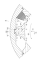
図2に示すように、固定子鉄心10Aが囲繞する回転子50の回転軸51に直交する断面による断面視で、ティース13Aは、内周面11に近づくほど内周面11の周方向Dcの幅Wが増大する拡幅部15を含む。一方、平角コイル20Aは、内周面11に近い巻回ほど内周面11の周方向Dcの幅wが減少する減幅部21を含む。
固定子鉄心10Aが囲繞する回転子50の回転軸51に直交する断面による断面視で、ティース13Aに回転する回転子50が接近する側の接近側部16と、ティース13Aに回転する回転子50が離脱する側の離脱側部17とにティース13Aは二分割されることができる。ティース13Aに回転する回転子50が接近する側とは、回転子50の回転方向DRとは反対方向の側である。ティース13Aに回転する回転子50が離脱する側とは、回転子50の回転方向DRの側である。二分割とは、例えば、回転子50の回転軸51を含む面で二分割されることを意味する。なお、二分割とは、ティース13Aが二分割された接近側部16と離脱側部17とを想定可能であればよく、ティース13Aが二分割された接近側部16と離脱側部17との別個の部材から構成されていることを要しない。
ティース13Aの接近側部16は、内周面11に近づくほど内周面11の周方向Dcの幅Wが連続して増大する拡幅部15を含む。幅Wが連続して増大するとは、例えば、回転子50の回転軸51に直交する断面による断面視で、径方向Drに平行な線及び径方向Drに直交する線により拡幅部15のスロット12の側の面が示されないことを意味する。一方、ティース13Aの離脱側部17では、内周面11からの距離に関わらず内周面11の周方向Dcの幅Wは一定である。平角コイル20Aの減幅部21は、接近側部16に巻回されている。一方、離脱側部17では、いずれの巻回も内周面11の周方向Dcの幅wは一定である。回転子50の回転軸51に直交する断面による断面視で、ティース13A及び平角コイル20Aは非対称である。
減幅部21では、内周面11の周方向Dcの幅wが減少するほど、内周面11の径方向Drの厚さtが増大する。また、平角コイル20Aの内周面11の周方向Dcの幅wと、平角コイル20Aの径方向Drの厚さtとの積が一定である。つまり、平角コイル20Aでは、平角コイル20Aの巻回方向に垂直な横断面による断面積は一定である。
なお、このような平角コイル20Aの各部で幅wと厚さtとが変動し、幅wと厚さtとの積が一定である平角コイル20Aを製造する際には、例えば、1回の巻回ごとに所望の幅wと厚さtとを有する1枚の板材が形成される。それらの板材は厚さtの方向に積層されつつ互いに接合される。それらの板材の互いに接合される部位以外の部位は互いに絶縁される。このようにして、本実施形態の平角コイル20Aを製造することができる。平角コイル20Aがティース13Aに組付けられた後に、ティース13Aはバックヨーク14に固定される。
本実施形態では、拡幅部15は、ティース13Aの接近側部16の内周面11の側の一部分に形成されている。また、本実施形態では、減幅部21は、ティース13Aの接近側部16の内周面11の側の一部分に巻回されている。また、本実施形態では、回転子50の回転軸51に直交する断面による断面視で、拡幅部15のスロット12の側の面は直線により示される。なお、拡幅部15は、ティース13Aの接近側部16がバックヨーク14から内周面11の側に延在する全部分に形成されていてもよい。また、減幅部21は、ティース13Aの接近側部16がバックヨーク14から内周面11の側に延在する全部分に巻回されていてもよい。また、回転子50の回転軸51に直交する断面による断面視で、拡幅部15のスロット12の側の面は直線により示されず、曲線により示されてもよい。
ティース13Aの接近側部16の近傍のスロット12は、セミオープンスロット型となる。セミオープンスロット型は、内周面11に開口するスロット12の開口部の周方向Dcの幅が、平角コイル20Aが装着される部分の周方向Dcの幅よりも狭いスロットである。一方、ティース13Aの接近側部16の近傍のスロット12は、従来通りのセミオープンスロット型又はオープンスロット型となる。オープンスロット型は、内周面11に開口するスロット12の開口部の周方向Dcの幅が、平角コイル20Aが装着される部分の周方向Dcの幅と同等以上であるスロットである。
本実施形態では、内周面11に開口する複数のスロット12と、互いに隣接するスロット12の間に形成された複数のティース13Aとを有する固定子鉄心10Aと、ティース13Aのそれぞれに巻回された平角コイル20Aとを備えた固定子1Aにおいて、固定子鉄心10Aが囲繞する回転子50の回転軸51に直交する断面による断面視で、ティース13Aは内周面11に近づくほど内周面11の周方向Dcの幅Wが増大する拡幅部15を含む。このため、磁束飽和を発生し難くし、漏れ磁束を低減し、平角コイル20Aで発生する渦電流損を低減することができる。
また、本実施形態では、平角コイル20Aは内周面11に近い巻回ほど内周面11の周方向Dcの幅wが減少する減幅部21を含む。固定子鉄心10Aが囲繞する回転子50の回転軸51に直交する断面による断面視で、ティース13Aに回転する回転子50が接近する側の接近側部16と、ティース13Aに回転する回転子50が離脱する側の離脱側部17とにティース13Aを二分割したときに、接近側部16は、内周面11に近づくほど内周面11の周方向Dcの幅Wが連続して増大する拡幅部15を含む。減幅部21は接近側部16に巻回されている。このため、磁束が飽和し易い接近側部16で磁束飽和を発生し難くし、漏れ磁束をより低減し、平角コイル20Aで発生する渦電流損をより低減することができる。
また、本実施形態では、減幅部21では、内周面11の周方向Dcの幅wが減少するほど、内周面11の径方向Drの厚さtが増大する。このため、平角コイル20Aの断面積の変動を低減することにより、平角コイル20Aの各部の抵抗値のばらつきを低減することができる。また、本実施形態では、平角コイル20Aの内周面11の周方向Dcの幅wと、平角コイル20Aの径方向Drの厚さtとの積が一定である。このため、平角コイル20Aの断面積を一定にすることにより、平角コイル20Aの各部の抵抗値を同一にすることができる。
つまり、図3に示すように、従来のオープンスロット型であり、ティース130に拡幅部15を含まない固定子鉄心110を備え、平角コイル200に減幅部21を含まない固定子100では、平角コイル200の表面積が大きい。このため、回転子50が回転したときに永久磁石等からの磁束が平角コイル200に到達すると、渦電流が発生する。そのため、渦電流損が大きくなり、電動機80のエネルギー効率を低下させる場合がある。
渦電流損を低減させるためには、セミオープンスロット型の固定子鉄心を用いることが考えられ、ティース130の先端部を磁路とすることで平角コイル200に到達する磁束が低減される。しかし、ティース130の先端部が磁束飽和を起こすと漏れ磁束が発生し、この磁束が平角コイル200に到達することで渦電流損が発生する。図3に示すような一般的なセミオープンスロット型の分割コアのティース130では、ティース13Aに回転する回転子50が接近する側のティース130の先端部において、磁束が飽和し易い。磁束飽和による漏れ磁束の発生が、平角コイル200で発生する渦電流損の要因となっている。
そこで、図2に示すように、本実施形態では、磁束飽和が生じないように、回転子50の回転軸51に直交する断面による断面視で非対称な形状を有するティース13Aが採用される。ティース13Aに回転する回転子50が接近する側の接近側部16は、内周面11に近づくほど内周面11の周方向Dcの幅Wが連続して増大する拡幅部15を含み、径方向Drの厚さが厚い。これにより、漏れ磁束が抑制され、平角コイル20Aで発生する渦電流損が低減される。
このようなティース13Aの形状により、平角コイル20Aの占積率が低下する可能性がある。しかし、本実施形態では、平角コイル20Aの減幅部21において、巻回ごとに、平角コイル20Aの幅wと厚さtとが変動することにより、占積率を低下させずに平角コイル20Aで発生する渦電流損の減少が可能である。ティース13Aに回転する回転子50が接近する側の離脱側部17では、接近側部16に比べて磁束飽和が発生し難い。そのため、離脱側部17では、平角コイル20Aのいずれの巻回も幅w及び厚さtは一定である。このように、本実施形態では、回転子50の回転軸51に直交する断面による断面視で非対称な形状を有する平角コイル20Aを採用することにより、占積率を向上させて銅損が低減される。
以下、本開示の第2実施形態について説明する。図4に示すように、本実施形態の固定子1Bでは、固定子鉄心10Bのティース13Bの接近側部16及び離脱側部17の両方は、内周面11に近づくほど内周面11の周方向Dcの幅が連続して増大する拡幅部15を含む。平角コイル20Bの減幅部21は、接近側部16及び離脱側部17の両方に巻回されている。回転子50の回転軸51に直交する断面による断面視で、ティース13B及び平角コイル20Bは対称である。
本実施形態では、拡幅部15は、ティース13Bの接近側部16及び離脱側部17の内周面11の側の一部分に形成されている。また、本実施形態では、減幅部21は、ティース13Bの接近側部16及び離脱側部17の内周面11の側の一部分に巻回されている。また、本実施形態では、回転子50の回転軸51に直交する断面による断面視で、拡幅部15のスロット12の側の面は直線により示される。
なお、拡幅部15は、ティース13Bの接近側部16及び離脱側部17がバックヨーク14から内周面11の側に延在する全部分に形成されていてもよい。また、減幅部21は、ティース13Bの接近側部16がバックヨーク14から内周面11の側に延在する全部分に巻回されていてもよい。また、回転子50の回転軸51に直交する断面による断面視で、拡幅部15のスロット12の側の面は直線ではなく、曲線により示されてもよい。また、本実施形態においては、接近側部16及び離脱側部17の両方が拡幅部15を含み、減幅部21は接近側部16及び離脱側部17の両方に巻回されていればよく、回転子50の回転軸51に直交する断面による断面視で、ティース13B及び平角コイル20Bは非対称であってもよい。その他の点については、上記第1実施形態と同様である。
本実施形態によれば、ティース13Bに接近側部16に加えて離脱側部17も内周面11に近づくほど内周面11の周方向Dcの幅Wが連続して増大する拡幅部15を含み、平角コイル20Bの減幅部21は接近側部16及び離脱側部17の両方に巻回されている。このため、接近側部16及び離脱側部17の両方で磁束飽和を発生し難くし、漏れ磁束をより低減し、平角コイル20Bで発生する渦電流損をより低減することができる。
以下、本開示の第3実施形態について説明する。図5に示すように、上記第2実施形態と同様に、本実施形態の固定子1Cでは、固定子鉄心10Cのティース13Cの接近側部16及び離脱側部17の両方は、内周面11に近づくほど内周面11の周方向Dcの幅Wが連続して増大する拡幅部15を含む。固定子鉄心10Cのティース13Cの接近側部16及び離脱側部17の両方は、スロット12に対向した面に流線形部13s、基部13r及び屈曲部13cを有する。
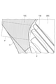
図6に示すように、拡幅部15のスロット12に対向する面の流線形部13sは、磁束線Fに沿った流線形状を有している。図6に磁束線F及び磁束密度が一様な部分Pで示すように、セミオープンスロットの場合、ティース13Cの先端を通る磁束は内周面11に近づくほど磁束密度が高まるため、磁束飽和を生じる。上述した第1実施形態及び第2実施形態では、磁束飽和の緩和のために拡幅部15が設けられた。しかし、上述したように、回転子50の回転軸51に直交する断面による断面視において、拡幅部15により、平角コイル20A,20Bを挿入可能な面積が減少し、電動機80の体格の増加を招き、エネルギー密度が低下する可能性がある。
回転子50の回転軸51に直交する断面による断面視における平角コイル20Cの挿入可能な面積減少を最小限に留めるために、本実施形態では、図6に示すように拡幅部15のスロット12に対向する面の流線形部13sは磁束線Fに沿った流線形状を有する。なお、図6において、説明の便宜のためにティース13C及び平角コイル20Cのハッチングは省略した。
本実施形態では、平角コイル20Cは内周面11に近い巻回ほど内周面11の周方向Dcの幅wが減少する減幅部21を含む。図5では、接近側部16の平角コイル20Cの図示を省略しているが、平角コイル20Cの減幅部21は、接近側部16及び離脱側部17の両方に巻回されている。回転子50の回転軸51に直交する断面による断面視で、ティース13C及び平角コイル20Cは対称である。
ティース13Cのスロット12に対向した面は、バックヨーク14の内周面が接する基部13rを有する。回転子50の回転軸51に直交する断面による断面視で、基部13rにおいて、ティース13Cのスロット12に対向した面と、バックヨーク14の内周面とは、鋭角をなす。
図7に示すように、スロット12に対向した面に複数の点C1,C2,C3,C4,C5,C6が仮定される。図8に示すように、ティース13Cの拡幅部15において、点C5において曲率が極大値を持つ。曲率が極大値となる点C5は、基部13rと内周面11との中間よりも内周面11の側に位置する。なお、C1からC6にまで至る拡幅部15の曲線において、曲率の中心はティース13Cの回転軸に直交する断面による断面視で、ティース13Cの外側に位置する。また、図5及び図7に示すように、ティース13Cは、スロット12に対向した面において、内周面11の近傍に内周面11の側に屈曲する屈曲部13cを有する。
その他の点については、上記第2実施形態と同様である。なお、本実施形態では、上記第1実施形態のように、ティース13Cの接近側部16にのみ、スロット12に対向した面に流線形部13s、基部13r及び屈曲部13cを有する形状でもよい。
本実施形態によれば、ティース13C及び平角コイル20Cが磁束の解析から導かれた形状を有する。このため、回転子50の回転軸51に直交する断面による断面視において、拡幅部15の面積を必要最小限に留め、最も効果的にエネルギー密度を高めることができる。なお、本実施形態のティース13Cは磁束線Fに沿った流線形状であるとしたが、流線形状と一致しなくても、流線形状の特徴と同様の特徴を備えるティース13Cであれば、エネルギー密度を高めることは可能である。
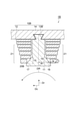
以下、本開示の第4実施形態について説明する。図9に示すように、本実施形態の固定子1Dでは、固定子鉄心10Dのティース13Dの接近側部16及び離脱側部17の両方は、内周面11に近づくほど内周面11の周方向Dcの幅が連続して増大する拡幅部15を含む。平角コイル20Dは、拡幅部15よりも内周面11から離隔した位置でティース13Dのそれぞれに巻回されている。平角コイル20Dは、減幅部21を有さない。平角コイル20Dのいずれの巻回も幅w及び厚さtは一定である。固定子1Dは、拡幅部15に隣接した冷却配管31を備える。冷却配管31は、例えば、樹脂製である。一方、固定子鉄心10Dを囲繞するケース30には、冷却配管は設けられていない。その他の点については、上記第2実施形態と同様である。
本実施形態によれば、平角コイル20Dは、拡幅部15よりも内周面11から離隔した位置でティース13Dのそれぞれに巻回されている。このため、平角コイル20Dに透過する磁束を低減し、平角コイル20Dで発生する渦電流損をより低減することができる。また、本実施形態によれば、拡幅部15に隣接した冷却配管31をさらに備える。このため、ティース13Dの拡幅部15の周囲のスペースを有効活用することによって、電動機80の体格の増加を抑えつつ、平角コイル20Dで発生する渦電流損をより低減することができる。
図3に示すように、従来の固定子100では、固定子100を囲繞するケース300に冷却配管301が設けられている。上述したように、ティース130では、ティース130の先端部において磁束が飽和し易く、磁束飽和による漏れ磁束の発生が平角コイル200で発生する渦電流損の要因となっている。そこで、本実施形態では、接近側部16及び離脱側部17は拡幅部15を含み、径方向Drの厚さが厚い。これにより、漏れ磁束が抑制され、平角コイル20Dで発生する渦電流損が低減される。さらに、平角コイル20Dは、拡幅部15よりも内周面11から離隔した位置でティース13Dのそれぞれに巻回されている。このため、平角コイル20Dに透過する磁束が低減され、平角コイル20Dで発生する渦電流損がより低減される。
このようなティース13Dの形状により、平角コイル20Dの占積率が低下する可能性がある。しかし、本実施形態では、スロット12の拡幅部15の近傍のデッドスペースに樹脂製の冷却配管31が配置され、スペースを有効活用し、ケース30の冷却配管を廃止することによって、電動機80の体格の増加を抑えつつ、平角コイル20Dで発生する渦電流損をより低減することができる。
以上、本開示の実施形態及び変形例について説明したが、本開示は、上記実施形態に限定されるものではない。
本開示の固定子によれば、平角コイルで発生する渦電流損を低減することができる。
1A,1B,1C,1D 固定子
10A,10B,10C,10D 固定子鉄心
11 内周面
12 スロット
13A,13B,13C,13D ティース
13s 流線形部
13r 基部
13c 屈曲部
14 バックヨーク
15 拡幅部
16 接近側部
17 離脱側部
20A,20B,20C,20D 平角コイル
21 減幅部
30 ケース
31 冷却配管
50 回転子
51 回転軸
80 電動機
100 固定子
110 固定子鉄心
130 ティース
200 平角コイル
300 ケース
301 冷却配管
Dc 周方向
Dr 径方向
DR 回転方向
W 幅
w 幅
t 厚さ
F 磁束線
P 部分
C1,C2,C3,C4,C5,C6 点
10A,10B,10C,10D 固定子鉄心
11 内周面
12 スロット
13A,13B,13C,13D ティース
13s 流線形部
13r 基部
13c 屈曲部
14 バックヨーク
15 拡幅部
16 接近側部
17 離脱側部
20A,20B,20C,20D 平角コイル
21 減幅部
30 ケース
31 冷却配管
50 回転子
51 回転軸
80 電動機
100 固定子
110 固定子鉄心
130 ティース
200 平角コイル
300 ケース
301 冷却配管
Dc 周方向
Dr 径方向
DR 回転方向
W 幅
w 幅
t 厚さ
F 磁束線
P 部分
C1,C2,C3,C4,C5,C6 点
Claims (7)
- 内周面に開口する複数のスロットと、互いに隣接する前記スロットの間に形成された複数のティースと、を有する固定子鉄心と、
前記ティースのそれぞれに巻回された平角コイルと、
を備え、
前記固定子鉄心が囲繞する回転子の回転軸に直交する断面による断面視で、
前記ティースは、前記内周面に近づくほど前記内周面の周方向の幅が増大する拡幅部を含む、固定子。 - 前記平角コイルは、前記拡幅部よりも前記内周面から離隔した位置で前記ティースのそれぞれに巻回されている、請求項1に記載の固定子。
- 前記平角コイルは、前記内周面に近い巻回ほど前記内周面の周方向の幅が減少する減幅部を含み、
前記固定子鉄心が囲繞する回転子の回転軸に直交する断面による断面視で、前記ティースに回転する前記回転子が接近する側の接近側部と、前記ティースに回転する前記回転子が離脱する側の離脱側部とに前記ティースを二分割したときに、
前記接近側部は、前記内周面に近づくほど前記内周面の周方向の幅が連続して増大する前記拡幅部を含み、
前記減幅部は、前記接近側部に巻回されている、請求項1又は2に記載の固定子。 - 前記離脱側部は、前記内周面に近づくほど前記内周面の周方向の幅が連続して増大する前記拡幅部を含み、
前記減幅部は、前記接近側部及び離脱側部に巻回されている、請求項3に記載の固定子。 - 前記減幅部では、前記内周面の周方向の幅が減少するほど、前記内周面の径方向の厚さが増大する、請求項3又は4に記載の固定子。
- 前記平角コイルの前記内周面の周方向の幅と、前記平角コイルの径方向の厚さとの積が一定である、請求項5に記載の固定子。
- 前記拡幅部に隣接した冷却配管をさらに備えた、請求項2に記載の固定子。
Priority Applications (3)
| Application Number | Priority Date | Filing Date | Title |
|---|---|---|---|
| US18/042,952 US12609570B2 (en) | 2020-08-27 | 2020-08-27 | Stator with flat angle coils with varying width and teeth having widened portions |
| PCT/JP2020/032460 WO2022044223A1 (ja) | 2020-08-27 | 2020-08-27 | 固定子 |
| EP20951476.9A EP4203244A4 (en) | 2020-08-27 | 2020-08-27 | STATOR |
Applications Claiming Priority (1)
| Application Number | Priority Date | Filing Date | Title |
|---|---|---|---|
| PCT/JP2020/032460 WO2022044223A1 (ja) | 2020-08-27 | 2020-08-27 | 固定子 |
Publications (1)
| Publication Number | Publication Date |
|---|---|
| WO2022044223A1 true WO2022044223A1 (ja) | 2022-03-03 |
Family
ID=80354935
Family Applications (1)
| Application Number | Title | Priority Date | Filing Date |
|---|---|---|---|
| PCT/JP2020/032460 Ceased WO2022044223A1 (ja) | 2020-08-27 | 2020-08-27 | 固定子 |
Country Status (3)
| Country | Link |
|---|---|
| US (1) | US12609570B2 (ja) |
| EP (1) | EP4203244A4 (ja) |
| WO (1) | WO2022044223A1 (ja) |
Families Citing this family (1)
| Publication number | Priority date | Publication date | Assignee | Title |
|---|---|---|---|---|
| JPWO2023162257A1 (ja) * | 2022-02-28 | 2023-08-31 |
Citations (5)
| Publication number | Priority date | Publication date | Assignee | Title |
|---|---|---|---|---|
| JPS62203527A (ja) | 1986-03-03 | 1987-09-08 | Hitachi Ltd | 回転機の電機子及びその製造方法 |
| JP2001502880A (ja) * | 1996-10-22 | 2001-02-27 | ヒル,ヴォルフガンク | 単極性の巻線のある電気機械 |
| JP2006014530A (ja) * | 2004-06-28 | 2006-01-12 | Sumitomo Electric Ind Ltd | コイルとその製造方法 |
| JP2007028777A (ja) * | 2005-07-15 | 2007-02-01 | Selco Co Ltd | 内径形状の異なる積層電磁コイル及び製造方法 |
| JP2014057441A (ja) * | 2012-09-13 | 2014-03-27 | Toyota Motor Corp | 回転電機のステータ |
Family Cites Families (36)
| Publication number | Priority date | Publication date | Assignee | Title |
|---|---|---|---|---|
| US2169100A (en) * | 1938-12-21 | 1939-08-08 | Gen Electric | Dynamo-electric machine |
| JPH0757086B2 (ja) | 1985-09-27 | 1995-06-14 | 株式会社テック | ハイブリツド形ステツピングモ−タ |
| JPH1132457A (ja) * | 1997-07-10 | 1999-02-02 | Toyota Motor Corp | 回転電機のステータ |
| JP4028100B2 (ja) | 1998-08-31 | 2007-12-26 | 株式会社東芝 | 回転電機のステータおよびステータの製造方法 |
| DE10057123A1 (de) * | 2000-11-16 | 2002-05-23 | Alcatel Sa | Stator für einen Elektromotor |
| US6573632B2 (en) * | 2001-07-06 | 2003-06-03 | Chun-Pu Hsu | Structure of a stator forming an annularly closed stable structure |
| US6737785B2 (en) * | 2002-05-20 | 2004-05-18 | Emerson Electric Co. | Method and apparatus for sealing an inner diameter of a segmented stator |
| US20040007933A1 (en) * | 2002-07-12 | 2004-01-15 | Chun-Pu Hsu | Assembly type stator structure having flat wire wound coils |
| US6822364B2 (en) * | 2002-07-30 | 2004-11-23 | Asmo Co., Ltd. | Brushless motor |
| US20050057106A1 (en) | 2002-12-10 | 2005-03-17 | Ballard Power Systems Corporation | Methods and systems for electric machines having windings |
| JP3987027B2 (ja) * | 2003-03-31 | 2007-10-03 | 三菱電機株式会社 | 回転電機の電機子 |
| JP2005160143A (ja) * | 2003-11-20 | 2005-06-16 | Toyota Motor Corp | 回転電機の固定子 |
| US7098565B2 (en) * | 2004-04-29 | 2006-08-29 | Lg Electronics Inc. | Core-coil assembly of motor and manufacturing method thereof |
| JP2006166610A (ja) | 2004-12-08 | 2006-06-22 | Sumitomo Electric Ind Ltd | ステータ、ステータの製造方法、及びロータ |
| JP2007020386A (ja) * | 2005-06-08 | 2007-01-25 | Denso Corp | 回転電機 |
| DE102005051506B4 (de) * | 2005-10-26 | 2025-03-13 | Sew-Eurodrive Gmbh & Co Kg | Elektromotor und Verfahren zum Herstellen eines Elektromotors |
| US20070182270A1 (en) * | 2006-02-08 | 2007-08-09 | Jaquar Precision Industry Co., Ltd. | Motor stator device |
| TW200822488A (en) * | 2006-09-08 | 2008-05-16 | Sanyo Electric Co | Motor |
| WO2008044703A1 (en) | 2006-10-12 | 2008-04-17 | Mitsubishi Electric Corporation | Stator of rotating electric machine |
| EP1959542B1 (en) * | 2007-02-13 | 2011-03-23 | Sanyo Denki Co., Ltd. | Stator for motor |
| JP4715776B2 (ja) * | 2007-03-06 | 2011-07-06 | トヨタ自動車株式会社 | モータ固定子の製造方法及びモータ固定子 |
| WO2010013444A1 (ja) | 2008-07-28 | 2010-02-04 | 株式会社日立製作所 | 永久磁石同期電動機 |
| JP2010115000A (ja) * | 2008-11-06 | 2010-05-20 | Nippon Densan Corp | モータ及びその製造方法 |
| JP5280895B2 (ja) | 2009-03-11 | 2013-09-04 | アスモ株式会社 | ステータコア、アキシャルギャップモータ及びステータコアの製造方法 |
| US20110037339A1 (en) * | 2009-08-12 | 2011-02-17 | Gm Global Technology Operations, Inc. | Concentrated winding machines with reduced torque ripple and methods for designing the same |
| JP5877035B2 (ja) * | 2011-10-31 | 2016-03-02 | 株式会社ミツバ | 平角線の巻線構造 |
| CN103187842B (zh) * | 2011-12-28 | 2015-07-01 | 日本电产株式会社 | 单相感应马达 |
| JP5376028B1 (ja) * | 2012-09-19 | 2013-12-25 | 株式会社安川電機 | ステータ及び回転電機 |
| JP2015012763A (ja) | 2013-07-02 | 2015-01-19 | 株式会社豊田自動織機 | ステータ |
| CN108141091B (zh) * | 2015-11-04 | 2020-03-03 | 三菱电机株式会社 | 定子、电动机、压缩机以及制冷空调装置 |
| JP6747834B2 (ja) | 2016-03-15 | 2020-08-26 | 株式会社Subaru | ステータ |
| US20180226845A1 (en) * | 2017-02-08 | 2018-08-09 | Wing Hang CHAN | Stator assembly |
| JP6710326B2 (ja) * | 2017-05-11 | 2020-06-17 | 三菱電機株式会社 | 回転電機の電機子鉄心 |
| DE102017208546A1 (de) | 2017-05-19 | 2018-11-22 | Mahle International Gmbh | Elektrische Maschine, insbesondere für ein Fahrzeug |
| JPWO2020080481A1 (ja) * | 2018-10-18 | 2021-09-09 | パナソニックIpマネジメント株式会社 | コイルの装着構造 |
| DE102019214518A1 (de) * | 2019-09-24 | 2021-03-25 | Rolls-Royce Deutschland Ltd & Co Kg | Statorzahnanordnung |
-
2020
- 2020-08-27 EP EP20951476.9A patent/EP4203244A4/en active Pending
- 2020-08-27 US US18/042,952 patent/US12609570B2/en active Active
- 2020-08-27 WO PCT/JP2020/032460 patent/WO2022044223A1/ja not_active Ceased
Patent Citations (5)
| Publication number | Priority date | Publication date | Assignee | Title |
|---|---|---|---|---|
| JPS62203527A (ja) | 1986-03-03 | 1987-09-08 | Hitachi Ltd | 回転機の電機子及びその製造方法 |
| JP2001502880A (ja) * | 1996-10-22 | 2001-02-27 | ヒル,ヴォルフガンク | 単極性の巻線のある電気機械 |
| JP2006014530A (ja) * | 2004-06-28 | 2006-01-12 | Sumitomo Electric Ind Ltd | コイルとその製造方法 |
| JP2007028777A (ja) * | 2005-07-15 | 2007-02-01 | Selco Co Ltd | 内径形状の異なる積層電磁コイル及び製造方法 |
| JP2014057441A (ja) * | 2012-09-13 | 2014-03-27 | Toyota Motor Corp | 回転電機のステータ |
Non-Patent Citations (1)
| Title |
|---|
| See also references of EP4203244A4 |
Also Published As
| Publication number | Publication date |
|---|---|
| US20230238845A1 (en) | 2023-07-27 |
| EP4203244A4 (en) | 2024-05-22 |
| US12609570B2 (en) | 2026-04-21 |
| EP4203244A1 (en) | 2023-06-28 |
Similar Documents
| Publication | Publication Date | Title |
|---|---|---|
| CN106953440A (zh) | 旋转电机、转子铁心的制造方法 | |
| JP2020137384A (ja) | 固定子 | |
| CN105723596B (zh) | 磁感应式电动机及其制造方法 | |
| JP2012228104A (ja) | 永久磁石埋込型電動機 | |
| JP6048191B2 (ja) | マルチギャップ型回転電機 | |
| JP5381139B2 (ja) | 電動機 | |
| EP4246774A1 (en) | Electric motor | |
| WO2022044223A1 (ja) | 固定子 | |
| JP6647464B1 (ja) | 回転子および回転電機 | |
| CN216056499U (zh) | 定子铁芯、电机、压缩机和空调器 | |
| CN106063085B (zh) | 转子 | |
| JP5303958B2 (ja) | 電動機および電動機固定子の固定方法 | |
| JP7677026B2 (ja) | 固定子 | |
| JP2022051033A (ja) | ステータ、及びモータ | |
| JP2000253603A (ja) | 誘導電動機の固定子鉄芯 | |
| JP5679695B2 (ja) | 永久磁石式回転電機 | |
| TWI882399B (zh) | 旋轉電機 | |
| JP7520998B2 (ja) | 回転子 | |
| JP2023017229A (ja) | 固定子 | |
| CN113708517B (zh) | 定子铁芯、电机、压缩机和空调器 | |
| JP7677027B2 (ja) | 固定子 | |
| JP5531773B2 (ja) | 回転電機 | |
| JP7388602B1 (ja) | 回転電機 | |
| CN115004511B (zh) | 定子及包括该定子的电动机 | |
| JP2020188591A (ja) | モータの回転子 |
Legal Events
| Date | Code | Title | Description |
|---|---|---|---|
| 121 | Ep: the epo has been informed by wipo that ep was designated in this application |
Ref document number: 20951476 Country of ref document: EP Kind code of ref document: A1 |
|
| ENP | Entry into the national phase |
Ref document number: 2020951476 Country of ref document: EP Effective date: 20230321 |
|
| NENP | Non-entry into the national phase |
Ref country code: DE |
|
| NENP | Non-entry into the national phase |
Ref country code: JP |