WO2022044506A1 - マイクロ流路デバイス、液滴の製造方法、気泡の製造方法、マイクロカプセルの製造方法、多重エマルションの製造方法、気泡を内包する液滴の製造方法及びマイクロ流路デバイスの製造方法 - Google Patents
マイクロ流路デバイス、液滴の製造方法、気泡の製造方法、マイクロカプセルの製造方法、多重エマルションの製造方法、気泡を内包する液滴の製造方法及びマイクロ流路デバイスの製造方法 Download PDFInfo
- Publication number
- WO2022044506A1 WO2022044506A1 PCT/JP2021/023220 JP2021023220W WO2022044506A1 WO 2022044506 A1 WO2022044506 A1 WO 2022044506A1 JP 2021023220 W JP2021023220 W JP 2021023220W WO 2022044506 A1 WO2022044506 A1 WO 2022044506A1
- Authority
- WO
- WIPO (PCT)
- Prior art keywords
- base
- flow path
- microchannel device
- surfactant
- producing
- Prior art date
- Legal status (The legal status is an assumption and is not a legal conclusion. Google has not performed a legal analysis and makes no representation as to the accuracy of the status listed.)
- Ceased
Links
Images


Classifications
-
- B—PERFORMING OPERATIONS; TRANSPORTING
- B81—MICROSTRUCTURAL TECHNOLOGY
- B81C—PROCESSES OR APPARATUS SPECIALLY ADAPTED FOR THE MANUFACTURE OR TREATMENT OF MICROSTRUCTURAL DEVICES OR SYSTEMS
- B81C1/00—Manufacture or treatment of devices or systems in or on a substrate
- B81C1/00015—Manufacture or treatment of devices or systems in or on a substrate for manufacturing microsystems
- B81C1/00023—Manufacture or treatment of devices or systems in or on a substrate for manufacturing microsystems without movable or flexible elements
- B81C1/00119—Arrangement of basic structures like cavities or channels, e.g. suitable for microfluidic systems
-
- B—PERFORMING OPERATIONS; TRANSPORTING
- B01—PHYSICAL OR CHEMICAL PROCESSES OR APPARATUS IN GENERAL
- B01F—MIXING, e.g. DISSOLVING, EMULSIFYING OR DISPERSING
- B01F23/00—Mixing according to the phases to be mixed, e.g. dispersing or emulsifying
- B01F23/20—Mixing gases with liquids
- B01F23/23—Mixing gases with liquids by introducing gases into liquid media, e.g. for producing aerated liquids
-
- B—PERFORMING OPERATIONS; TRANSPORTING
- B01—PHYSICAL OR CHEMICAL PROCESSES OR APPARATUS IN GENERAL
- B01F—MIXING, e.g. DISSOLVING, EMULSIFYING OR DISPERSING
- B01F23/00—Mixing according to the phases to be mixed, e.g. dispersing or emulsifying
- B01F23/40—Mixing liquids with liquids; Emulsifying
- B01F23/41—Emulsifying
-
- B—PERFORMING OPERATIONS; TRANSPORTING
- B01—PHYSICAL OR CHEMICAL PROCESSES OR APPARATUS IN GENERAL
- B01F—MIXING, e.g. DISSOLVING, EMULSIFYING OR DISPERSING
- B01F25/00—Flow mixers; Mixers for falling materials, e.g. solid particles
- B01F25/30—Injector mixers
- B01F25/31—Injector mixers in conduits or tubes through which the main component flows
- B01F25/314—Injector mixers in conduits or tubes through which the main component flows wherein additional components are introduced at the circumference of the conduit
-
- B—PERFORMING OPERATIONS; TRANSPORTING
- B01—PHYSICAL OR CHEMICAL PROCESSES OR APPARATUS IN GENERAL
- B01F—MIXING, e.g. DISSOLVING, EMULSIFYING OR DISPERSING
- B01F33/00—Other mixers; Mixing plants; Combinations of mixers
- B01F33/30—Micromixers
-
- B—PERFORMING OPERATIONS; TRANSPORTING
- B01—PHYSICAL OR CHEMICAL PROCESSES OR APPARATUS IN GENERAL
- B01F—MIXING, e.g. DISSOLVING, EMULSIFYING OR DISPERSING
- B01F33/00—Other mixers; Mixing plants; Combinations of mixers
- B01F33/30—Micromixers
- B01F33/302—Micromixers the materials to be mixed flowing in the form of droplets
- B01F33/3021—Micromixers the materials to be mixed flowing in the form of droplets the components to be mixed being combined in a single independent droplet, e.g. these droplets being divided by a non-miscible fluid or consisting of independent droplets
-
- B—PERFORMING OPERATIONS; TRANSPORTING
- B01—PHYSICAL OR CHEMICAL PROCESSES OR APPARATUS IN GENERAL
- B01J—CHEMICAL OR PHYSICAL PROCESSES, e.g. CATALYSIS OR COLLOID CHEMISTRY; THEIR RELEVANT APPARATUS
- B01J13/00—Colloid chemistry, e.g. the production of colloidal materials or their solutions, not otherwise provided for; Making microcapsules or microballoons
- B01J13/02—Making microcapsules or microballoons
- B01J13/06—Making microcapsules or microballoons by phase separation
- B01J13/08—Simple coacervation, i.e. addition of highly hydrophilic material
-
- B—PERFORMING OPERATIONS; TRANSPORTING
- B01—PHYSICAL OR CHEMICAL PROCESSES OR APPARATUS IN GENERAL
- B01J—CHEMICAL OR PHYSICAL PROCESSES, e.g. CATALYSIS OR COLLOID CHEMISTRY; THEIR RELEVANT APPARATUS
- B01J13/00—Colloid chemistry, e.g. the production of colloidal materials or their solutions, not otherwise provided for; Making microcapsules or microballoons
- B01J13/02—Making microcapsules or microballoons
- B01J13/06—Making microcapsules or microballoons by phase separation
- B01J13/14—Polymerisation; cross-linking
-
- B—PERFORMING OPERATIONS; TRANSPORTING
- B01—PHYSICAL OR CHEMICAL PROCESSES OR APPARATUS IN GENERAL
- B01J—CHEMICAL OR PHYSICAL PROCESSES, e.g. CATALYSIS OR COLLOID CHEMISTRY; THEIR RELEVANT APPARATUS
- B01J13/00—Colloid chemistry, e.g. the production of colloidal materials or their solutions, not otherwise provided for; Making microcapsules or microballoons
- B01J13/02—Making microcapsules or microballoons
- B01J13/06—Making microcapsules or microballoons by phase separation
- B01J13/14—Polymerisation; cross-linking
- B01J13/16—Interfacial polymerisation
-
- B—PERFORMING OPERATIONS; TRANSPORTING
- B01—PHYSICAL OR CHEMICAL PROCESSES OR APPARATUS IN GENERAL
- B01J—CHEMICAL OR PHYSICAL PROCESSES, e.g. CATALYSIS OR COLLOID CHEMISTRY; THEIR RELEVANT APPARATUS
- B01J13/00—Colloid chemistry, e.g. the production of colloidal materials or their solutions, not otherwise provided for; Making microcapsules or microballoons
- B01J13/02—Making microcapsules or microballoons
- B01J13/06—Making microcapsules or microballoons by phase separation
- B01J13/14—Polymerisation; cross-linking
- B01J13/18—In situ polymerisation with all reactants being present in the same phase
-
- B—PERFORMING OPERATIONS; TRANSPORTING
- B81—MICROSTRUCTURAL TECHNOLOGY
- B81B—MICROSTRUCTURAL DEVICES OR SYSTEMS, e.g. MICROMECHANICAL DEVICES
- B81B1/00—Devices without movable or flexible elements, e.g. microcapillary devices
-
- C—CHEMISTRY; METALLURGY
- C08—ORGANIC MACROMOLECULAR COMPOUNDS; THEIR PREPARATION OR CHEMICAL WORKING-UP; COMPOSITIONS BASED THEREON
- C08L—COMPOSITIONS OF MACROMOLECULAR COMPOUNDS
- C08L29/00—Compositions of homopolymers or copolymers of compounds having one or more unsaturated aliphatic radicals, each having only one carbon-to-carbon double bond, and at least one being terminated by an alcohol, ether, aldehydo, ketonic, acetal or ketal radical; Compositions of hydrolysed polymers of esters of unsaturated alcohols with saturated carboxylic acids; Compositions of derivatives of such polymers
- C08L29/02—Homopolymers or copolymers of unsaturated alcohols
- C08L29/04—Polyvinyl alcohol; Partially hydrolysed homopolymers or copolymers of esters of unsaturated alcohols with saturated carboxylic acids
-
- C—CHEMISTRY; METALLURGY
- C08—ORGANIC MACROMOLECULAR COMPOUNDS; THEIR PREPARATION OR CHEMICAL WORKING-UP; COMPOSITIONS BASED THEREON
- C08L—COMPOSITIONS OF MACROMOLECULAR COMPOUNDS
- C08L83/00—Compositions of macromolecular compounds obtained by reactions forming in the main chain of the macromolecule a linkage containing silicon with or without sulfur, nitrogen, oxygen or carbon only; Compositions of derivatives of such polymers
- C08L83/04—Polysiloxanes
-
- B—PERFORMING OPERATIONS; TRANSPORTING
- B01—PHYSICAL OR CHEMICAL PROCESSES OR APPARATUS IN GENERAL
- B01J—CHEMICAL OR PHYSICAL PROCESSES, e.g. CATALYSIS OR COLLOID CHEMISTRY; THEIR RELEVANT APPARATUS
- B01J2219/00—Chemical, physical or physico-chemical processes in general; Their relevant apparatus
- B01J2219/00781—Aspects relating to microreactors
- B01J2219/00783—Laminate assemblies, i.e. the reactor comprising a stack of plates
-
- B—PERFORMING OPERATIONS; TRANSPORTING
- B01—PHYSICAL OR CHEMICAL PROCESSES OR APPARATUS IN GENERAL
- B01J—CHEMICAL OR PHYSICAL PROCESSES, e.g. CATALYSIS OR COLLOID CHEMISTRY; THEIR RELEVANT APPARATUS
- B01J2219/00—Chemical, physical or physico-chemical processes in general; Their relevant apparatus
- B01J2219/00781—Aspects relating to microreactors
- B01J2219/00801—Means to assemble
- B01J2219/00804—Plurality of plates
-
- B—PERFORMING OPERATIONS; TRANSPORTING
- B01—PHYSICAL OR CHEMICAL PROCESSES OR APPARATUS IN GENERAL
- B01J—CHEMICAL OR PHYSICAL PROCESSES, e.g. CATALYSIS OR COLLOID CHEMISTRY; THEIR RELEVANT APPARATUS
- B01J2219/00—Chemical, physical or physico-chemical processes in general; Their relevant apparatus
- B01J2219/00781—Aspects relating to microreactors
- B01J2219/00819—Materials of construction
- B01J2219/00822—Metal
-
- B—PERFORMING OPERATIONS; TRANSPORTING
- B01—PHYSICAL OR CHEMICAL PROCESSES OR APPARATUS IN GENERAL
- B01J—CHEMICAL OR PHYSICAL PROCESSES, e.g. CATALYSIS OR COLLOID CHEMISTRY; THEIR RELEVANT APPARATUS
- B01J2219/00—Chemical, physical or physico-chemical processes in general; Their relevant apparatus
- B01J2219/00781—Aspects relating to microreactors
- B01J2219/00819—Materials of construction
- B01J2219/00831—Glass
-
- B—PERFORMING OPERATIONS; TRANSPORTING
- B01—PHYSICAL OR CHEMICAL PROCESSES OR APPARATUS IN GENERAL
- B01J—CHEMICAL OR PHYSICAL PROCESSES, e.g. CATALYSIS OR COLLOID CHEMISTRY; THEIR RELEVANT APPARATUS
- B01J2219/00—Chemical, physical or physico-chemical processes in general; Their relevant apparatus
- B01J2219/00781—Aspects relating to microreactors
- B01J2219/00819—Materials of construction
- B01J2219/00833—Plastic
-
- B—PERFORMING OPERATIONS; TRANSPORTING
- B81—MICROSTRUCTURAL TECHNOLOGY
- B81B—MICROSTRUCTURAL DEVICES OR SYSTEMS, e.g. MICROMECHANICAL DEVICES
- B81B2201/00—Specific applications of microelectromechanical systems
- B81B2201/05—Microfluidics
- B81B2201/058—Microfluidics not provided for in B81B2201/051 - B81B2201/054
-
- B—PERFORMING OPERATIONS; TRANSPORTING
- B81—MICROSTRUCTURAL TECHNOLOGY
- B81B—MICROSTRUCTURAL DEVICES OR SYSTEMS, e.g. MICROMECHANICAL DEVICES
- B81B2203/00—Basic microelectromechanical structures
- B81B2203/03—Static structures
- B81B2203/0323—Grooves
- B81B2203/0338—Channels
-
- B—PERFORMING OPERATIONS; TRANSPORTING
- B81—MICROSTRUCTURAL TECHNOLOGY
- B81C—PROCESSES OR APPARATUS SPECIALLY ADAPTED FOR THE MANUFACTURE OR TREATMENT OF MICROSTRUCTURAL DEVICES OR SYSTEMS
- B81C2201/00—Manufacture or treatment of microstructural devices or systems
- B81C2201/01—Manufacture or treatment of microstructural devices or systems in or on a substrate
- B81C2201/0174—Manufacture or treatment of microstructural devices or systems in or on a substrate for making multi-layered devices, film deposition or growing
- B81C2201/019—Bonding or gluing multiple substrate layers
-
- B—PERFORMING OPERATIONS; TRANSPORTING
- B81—MICROSTRUCTURAL TECHNOLOGY
- B81C—PROCESSES OR APPARATUS SPECIALLY ADAPTED FOR THE MANUFACTURE OR TREATMENT OF MICROSTRUCTURAL DEVICES OR SYSTEMS
- B81C2203/00—Forming microstructural systems
- B81C2203/03—Bonding two components
- B81C2203/038—Bonding techniques not provided for in B81C2203/031 - B81C2203/037
-
- C—CHEMISTRY; METALLURGY
- C08—ORGANIC MACROMOLECULAR COMPOUNDS; THEIR PREPARATION OR CHEMICAL WORKING-UP; COMPOSITIONS BASED THEREON
- C08L—COMPOSITIONS OF MACROMOLECULAR COMPOUNDS
- C08L2201/00—Properties
- C08L2201/52—Aqueous emulsion or latex, e.g. containing polymers of a glass transition temperature (Tg) below 20°C
-
- C—CHEMISTRY; METALLURGY
- C08—ORGANIC MACROMOLECULAR COMPOUNDS; THEIR PREPARATION OR CHEMICAL WORKING-UP; COMPOSITIONS BASED THEREON
- C08L—COMPOSITIONS OF MACROMOLECULAR COMPOUNDS
- C08L2207/00—Properties characterising the ingredient of the composition
- C08L2207/32—Properties characterising the ingredient of the composition containing low molecular weight liquid component
- C08L2207/324—Liquid component is low molecular weight polymer
Definitions
- the present disclosure relates to a microchannel device, a droplet manufacturing method, a bubble manufacturing method, a microcapsule manufacturing method, a multiple emulsion manufacturing method, a droplet manufacturing method containing bubbles, and a microchannel device manufacturing method. ..
- a microchannel device is a device that includes a microchannel through which a fluid flows. Fluid is a general term for liquids and gases.
- the flow path of the microchannel device is utilized, for example, for mixing, separation, analysis or reaction.
- Microchannel The channel of the device is formed using microfabrication techniques such as photolithography. For example, the flow path of the microchannel device is formed through a process of transferring the shape of a mold produced by using a photoresist to silicone rubber.
- the flow path of the microchannel device formed by the method as described above is defined by the surface of the silicone rubber.
- Non-Patent Document 1 discloses a microchannel device manufactured by using a fluoroelastomer.
- microchannel devices are manufactured by laminating two members together.
- a polymer containing a fluorine atom such as a fluorine elastomer has high resistance to an organic solvent
- a member containing a polymer containing a fluorine atom and another member are attached in the manufacture of a microchannel device. It is difficult to match.
- the disclosure includes the following aspects: ⁇ 1> It has a demarcation surface that defines the flow path, and has a first base containing a polymer containing a fluorine atom and a demarcation surface that defines the flow path together with the demarcation surface of the first base.
- the surface of the first base exposed by peeling the second base from the first base, including a second base having solvent resistance and in contact with the first base.
- a microchannel device having an arithmetic mean roughness Ra of 1 ⁇ m or more.
- the second base contains at least one selected from the group consisting of a polymer containing a fluorine atom, glass, and stainless steel.
- the contact angle of water with respect to the demarcating surface of the first base is 90 ° or more, and the contact angle of water with respect to the demarcating surface of the second base is 90 ° or more.
- the demarcated surface of the first base includes a region where the surfactant is adsorbed, and the contact angle of water with respect to the region where the surfactant is adsorbed on the demarcated surface of the first base is set.
- the temperature is 60 ° or less
- the demarcating surface of the second base includes a region on which the surfactant is adsorbed, and water for the demarcating surface of the second base on which the surfactant is adsorbed.
- the surfactant is an alkylene oxide polymer.
- the surfactant is an ethylene oxide-propylene oxide copolymer.
- the demarcating surface of the first base further includes a region not adsorbing the surfactant, and the demarcating surface of the second base further includes a region not adsorbing the surfactant.
- ⁇ 8> The first flow path portion, the second flow path portion where the flow path merges with the first flow path portion, the first flow path portion, and the second flow path portion.
- the microchannel device according to any one of ⁇ 1> to ⁇ 7>, comprising a third channel portion connected to the confluence of the above.
- ⁇ 9> The first flow path portion, the second flow path portion where the flow path merges with the first flow path portion, the first flow path portion, and the second flow path portion.
- a third flow path portion connected to the confluence point of the above, a fourth flow path portion merging with the third flow path portion, and a confluence of the third flow path portion and the fourth flow path portion.
- the microchannel device according to any one of ⁇ 1> to ⁇ 7> comprising a fifth channel portion connected to a point.
- the microchannel device according to any one of ⁇ 1> to ⁇ 9> which is used for producing a droplet.
- the microchannel device according to any one of ⁇ 1> to ⁇ 9> which is used for producing bubbles.
- the microchannel device according to any one of ⁇ 1> to ⁇ 9> which is used for producing microcapsules.
- ⁇ 14> The microchannel device according to any one of ⁇ 1> to ⁇ 9>, which is used for producing a droplet containing bubbles.
- ⁇ 15> The method for producing a droplet using the microchannel device according to any one of ⁇ 1> to ⁇ 9>, which comprises a liquid containing oil and water in the channel of the microchannel device.
- a method for producing a droplet which comprises merging with a liquid to obtain a droplet.
- ⁇ 16> The method for producing bubbles using the microchannel device according to any one of ⁇ 1> to ⁇ 9>, wherein the liquid and the gas are merged in the channel of the microchannel device.
- a method for producing a bubble which comprises obtaining the bubble.
- a method for producing microcapsules which comprises merging with a liquid to obtain microcapsules.
- a method for producing a multiple emulsion which comprises obtaining a multiple emulsion.
- a method for producing a droplet containing bubbles which comprises merging a liquid containing oil and a liquid containing water to obtain a droplet containing the bubble.
- a method of manufacturing a microchannel device comprising forming a flow path defined by a base and the second base.
- a microchannel device having excellent solvent resistance and adhesiveness is provided.
- a method for producing a droplet using a microchannel device having excellent solvent resistance and adhesion there is provided a method for producing bubbles using a microchannel device having excellent solvent resistance and adhesiveness.
- a method for producing microcapsules using a microchannel device having excellent solvent resistance and adhesiveness there is provided a method for producing a multiple emulsion using a microchannel device having excellent solvent resistance and adhesiveness.
- a method for producing a droplet containing bubbles using a microchannel device having excellent solvent resistance and adhesiveness there is provided a method for manufacturing a microchannel device having excellent solvent resistance and adhesiveness.
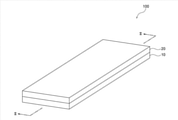
- FIG. 1 is a schematic perspective view showing a microchannel device according to an embodiment of the present disclosure.
- FIG. 2 is a schematic cross-sectional view taken along line II-II shown in FIG.
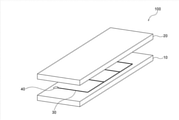
- FIG. 3 is a schematic exploded perspective view of the microchannel device shown in FIG.
- FIG. 4 is a schematic plan view of the microchannel device shown in FIG.
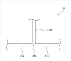
- FIG. 5 is a schematic plan view showing the flow path of the micro flow path device according to the embodiment of the present disclosure.
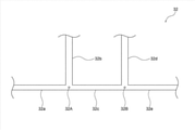
- FIG. 6 is a schematic plan view showing the flow path of the micro flow path device according to the embodiment of the present disclosure.
- FIG. 7 is a schematic plan view showing the flow aspect of the fluid in the flow path of the microchannel device according to the embodiment of the present disclosure.
- the numerical range indicated by using "-" indicates a range including the numerical values before and after "-" as the lower limit value and the upper limit value, respectively.
- the upper limit value or the lower limit value described in one numerical range may be replaced with the upper limit value or the lower limit value of the numerical range described in another stepwise description.
- the upper limit value or the lower limit value described in a certain numerical range may be replaced with the value shown in the examples.
- the amount of each component in the composition means the total amount of the plurality of substances present in the composition when a plurality of substances corresponding to each component are present in the composition, unless otherwise specified. ..
- ordinal numbers are terms used to distinguish a plurality of components and limit the number of components and the superiority or inferiority of the components. is not it.
- process is included in this term not only as an independent process but also as long as the intended purpose of the process is achieved even if it cannot be clearly distinguished from other processes. ..
- the microchannel device has a demarcating surface that defines a channel, and includes a first base containing a polymer containing a fluorine atom and the demarcating surface of the first base. It has a demarcating surface that defines the flow path, has solvent resistance, and includes a second base that contacts the first base.
- the arithmetic average roughness Ra of the surface of the first base exposed by peeling the second base from the first base is 1 ⁇ m or more.
- a microchannel device having excellent solvent resistance and adhesiveness is provided.
- “adhesiveness” means the adhesion (also referred to as adhesiveness) between the first base portion and the second base portion.
- solvent resistance means resistance to organic solvents.
- the microchannel device includes a first base containing a polymer containing a fluorine atom and a second base having solvent resistance.
- the first and second bases as described above improve the solvent resistance of the microchannel device.
- the surface of the first base portion exposed by peeling the second base portion from the first base portion hereinafter, may be referred to as “exposed surface”.
- the arithmetic mean roughness Ra of (.) Is 1 ⁇ m or more.
- the arithmetic mean roughness Ra of the exposed surface represents the aspect of fracture caused by peeling. For example, if the adhesion between the first base and the second base is lower than the cohesive force acting inside the first base or the second base, the second base is peeled off from the first base. In the process, peeling occurs mainly at the interface between the first base and the second base. When peeling occurs at the interface between the first base and the second base, the arithmetic mean roughness Ra of the exposed surface becomes smaller. On the other hand, when the adhesion between the first base and the second base is higher than the cohesive force acting inside the first base or the second base, the second base is peeled off from the first base. Destruction occurs primarily within the first or second base in the process.
- the arithmetic mean roughness Ra of the exposed surface becomes large. That is, the characteristic that "the arithmetic average roughness Ra of the exposed surface is 1 ⁇ m or more" is the fracture that occurs inside the first base or the second base in the process of peeling the second base from the first base. Indicates that is predominant, in other words, the adhesion between the first base and the second base is high. Therefore, according to one embodiment of the present disclosure, a microchannel device having excellent solvent resistance and adhesiveness is provided. Hereinafter, the microchannel device will be specifically described.
- the arithmetic mean roughness Ra of the surface (that is, the exposed surface) of the first base exposed by peeling the second base from the first base is It is 1 ⁇ m or more.
- the arithmetic average roughness Ra of the exposed surface is preferably 2 ⁇ m or more, more preferably 3 ⁇ m or more, and particularly preferably 5 ⁇ m or more.
- the upper limit of the arithmetic mean roughness Ra of the exposed surface is not limited.
- the upper limit of the arithmetic mean roughness Ra of the exposed surface may be, for example, 300 ⁇ m, 500 ⁇ m, or 1000 ⁇ m.
- the arithmetic average roughness Ra of the exposed surface is preferably 1 ⁇ m to 1000 ⁇ m, more preferably 2 ⁇ m to 500 ⁇ m, and particularly preferably 3 ⁇ m to 300 ⁇ m.
- the arithmetic mean roughness Ra of the exposed surface is measured by the following method.
- the peeling angle is 90 °.
- the second base is stripped from the first base of the microchannel device at a 90 ° angle.
- the microchannel device is divided into two test pieces.
- the two test pieces include a test piece divided into a first base side and a test piece divided into a second base side.
- the test piece divided on the first base side (hereinafter, referred to as "first test piece") may include a part of the second base.
- Arithmetic mean roughness Ra of the surface of the first test piece (excluding the region defining the flow path of the microchannel device) exposed by peeling was measured with a laser optical microscope (eg, VK8550, Inc.). Measure using a keyence).
- the microchannel device has a demarcating surface defining a channel and includes a first base containing a polymer containing a fluorine atom.
- the first base containing the polymer containing a fluorine atom improves the solvent resistance of the microchannel device.
- the first base will be specifically described.
- the type of polymer containing a fluorine atom is not limited.
- the polymer containing a fluorine atom in the present disclosure includes a known polymer containing a fluorine atom.
- Examples of the polymer containing a fluorine atom include fluoropolyether, polytetrafluoroethylene and perfluoroalkoxyethylene. From the viewpoint of solvent resistance and transparency, the polymer containing a fluorine atom is preferably a fluoropolyether.
- Fluoropolyether is a polymer containing a fluoroalkyleneoxy group.
- the fluoropolyether may contain two or more fluoroalkyleneoxy groups.
- the fluoroalkylene oxy group may be, for example, a linear fluoroalkylene oxy group or a branched fluoroalkylene oxy group.
- the fluoroalkylene oxy group is preferably a perfluoroalkylene oxy group.
- the fluoroalkylene oxy group is preferably a fluoroalkylene oxy group having 2 to 6 carbon atoms, and more preferably a fluoroalkylene oxy group having 2 to 4 carbon atoms.
- the polymer containing a fluorine atom may contain, for example, an atom other than the fluorine atom and the carbon atom.
- the polymer containing a fluorine atom preferably contains a silicon atom.
- the first base may contain a polymer containing two or more fluorine atoms.
- the content of the polymer containing a fluorine atom in the first base is not limited. From the viewpoint of improving solvent resistance, the content of the polymer containing a fluorine atom in the first base is preferably 70% by mass to 100% by mass, preferably 80% by mass, based on the total mass of the first base. It is preferably% to 100% by mass, and particularly preferably 90% by mass to 100% by mass. The content of the polymer containing a fluorine atom in the first base may be less than 100% by mass with respect to the total mass of the first base.
- the demarcating surface of the first base defines the flow path of the microchannel device. That is, the demarcated surface of the first base is the surface of the base facing the flow path.
- the number of demarcated faces of the first base is not limited.
- the first base may have two or more demarcation planes.
- the shape of the demarcated surface of the first base is not limited.
- the demarcating surface of the first base may be, for example, a plane or a curved surface.
- the contact angle of water with respect to the demarcated surface of the first base is preferably 90 ° or more, more preferably 95 ° or more. It is preferably 100 ° or more, and particularly preferably 100 ° or more.
- the contact angle is 90 ° or more, the affinity of the liquid containing water for the demarcated surface of the first base is reduced. The reduced affinity of the liquid containing water for the demarcated surface of the first base promotes, for example, the formation of water droplets.
- the upper limit of the contact angle is not limited. The upper limit of the contact angle may be, for example, 140 °, 130 ° or 120 °.
- the contact angle is preferably 90 ° to 140 °, more preferably 95 ° to 130 °, and particularly preferably 100 ° to 120 °.
- the contact angle of water is measured by the following method. At room temperature of 25 ° C., 2 ⁇ L of pure water is added dropwise to the horizontal target surface. The contact angle of the droplet 1 second after the contact of pure water with the target surface is measured using a contact angle meter (for example, DMs-401, Kyowa Interface Science Co., Ltd.). The obtained value is adopted as the contact angle of water.
- a contact angle meter for example, DMs-401, Kyowa Interface Science Co., Ltd.
- Polymers containing fluorine atoms usually tend to be hydrophobic.
- the hydrophobic solid surface defining the channel eg, the demarcating surface of the first base
- the sample flowing through the channel eg, enzymes and proteins.
- the solid surface defining the channel has a high affinity for a liquid containing water used as a solvent.
- At least a part of the hydrophilicity of the solid surface (for example, the demarcating surface of the first base) defining the flow path of the microchannel device according to an embodiment. It is preferable to improve the sex.
- the demarcated surface of the first base preferably contains a region adsorbing a surfactant. That is, it is preferable that the surfactant is adsorbed on at least a part of the demarcated surface of the first base.
- the region on which the surfactant is adsorbed improves the hydrophilicity of the solid surface that defines the flow path. Improving the hydrophilicity of the solid surface that defines the flow path promotes, for example, the formation of oil droplets.
- the position of the region on which the surfactant is adsorbed is not limited on the demarcated surface of the first base.
- the region on which the surfactant is adsorbed may be arranged on all or part of the demarcation surface of the first base.
- the mode of adsorption is not limited.
- the adsorption may be, for example, physical adsorption or chemisorption.
- the surfactant adsorbed on the demarcated surface of the first base is detected, for example, by time-of-flight secondary ion mass spectrometry described later.
- the type of the surfactant adsorbed on the demarcating surface of the first base may be one type or two or more types.
- the type of surfactant is not limited.
- the surfactants in the present disclosure include known surfactants.
- Examples of the surfactant include a cationic surfactant, an anionic surfactant, an amphoteric surfactant and a nonionic surfactant.
- the surfactant is preferably a nonionic surfactant.
- the nonionic surfactant is preferably a polymer, more preferably an alkylene oxide polymer, and particularly preferably an ethylene oxide-propylene oxide copolymer.
- the alkylene oxide polymer is a polymer containing an alkyleneoxy group.
- the alkylene oxide polymer used as a surfactant can be strongly adsorbed on the solid surface defining the channel and the hydrophilic group of the alkylene oxide polymer adsorbed on the solid surface defining the channel. Is stably arranged facing the flow path.
- the alkylene oxide polymer used as a surfactant can not only improve the hydrophilicity but also suppress, for example, the decrease in hydrophilicity over time.
- the hydrophilicity of the solid surface on which the alkylene oxide polymer is adsorbed as a surfactant is unlikely to decrease even in an environment where the speed of the fluid flowing through the flow path is high.
- the alkylene oxide polymer may contain two or more alkyleneoxy groups.
- the alkylene oxide polymer may contain an alkyleneoxy group in both the main chain, the side chain or both the main chain and the side chain.
- the alkylene oxide polymer preferably contains an alkyleneoxy group in the main chain.
- the alkyleneoxy group may be, for example, a linear alkyleneoxy group or a branched alkyleneoxy group.
- the alkyleneoxy group is preferably an alkyleneoxy group having 2 to 6 carbon atoms, and more preferably an alkyleneoxy group having 2 to 3 carbon atoms. Examples of the alkyleneoxy group include an ethyleneoxy group and a propyleneoxy group.
- the ethylene oxide-propylene oxide copolymer is a copolymer containing an ethyleneoxy group and a propyleneoxy group.
- the surfactant preferably has high biocompatibility.
- Commercially available products of surfactants include, for example, "Pluronic” (trade name, BASF, eg, F68 and F127).
- the molecular weight of the surfactant is not limited. From the viewpoint of improving hydrophilicity, the molecular weight of the surfactant is preferably 2,000 or more, more preferably 5,000 or more, and particularly preferably 10,000 or more.
- the molecular weight of the surfactant is preferably 100,000 or less, preferably 50,000 or less, from the viewpoint of the viscosity of the composition containing the surfactant used in the method for producing a microchannel device. It is more preferably 20,000 or less, and particularly preferably 20,000 or less.
- the molecular weight of the surfactant is preferably 2,000 to 100,000, more preferably 5,000 to 50,000, and particularly preferably 10,000 to 20,000.
- the molecular weight of a surfactant having a molecular weight distribution is expressed by a weight average molecular weight. In the present disclosure, the weight average molecular weight is measured by gel permeation chromatography (GPC).
- the amount of surfactant adsorbed on the demarcated surface of the first base is expressed by the ratio of the amount of secondary ions of the surfactant to the total amount of ions detected by time-of-flight secondary ion mass spectrometry (TOF-SIMS). Will be done. From the viewpoint of improving hydrophilicity, the ratio of the amount of secondary ions of the surfactant adsorbed on the demarcated surface of the second base to the total amount of ions detected by TOF-SIMS (hereinafter, "of the surfactant" in this paragraph.
- the "adsorption amount" is preferably 0.01 or more, more preferably 0.015 or more, further preferably 0.02 or more, and particularly preferably 0.025 or more. ..
- the upper limit of the adsorption amount of the surfactant is not limited.
- the upper limit of the adsorption amount of the surfactant may be, for example, 0.5, 0.3 or 0.1.
- the adsorption amount of the surfactant is preferably 0.01 to 0.5, more preferably 0.015 to 0.3, still more preferably 0.02 to 0.1, and 0. It is particularly preferable that it is .025 to 0.1.
- the ratio of the amount of secondary ions of the surfactant adsorbed on the target surface to the total amount of ions detected by time-of-flight secondary ion mass spectrometry is measured by the following method.
- TOF-SIMS a known time-of-flight mass spectrometer is used.
- the contact angle of water with respect to the region where the surfactant is adsorbed on the demarcated surface of the first base shall be 60 ° or less. Is preferable, 50 ° or less is more preferable, and 40 ° or less is particularly preferable.
- the lower limit of the contact angle is not limited. The lower limit of the contact angle may be, for example, 5 °, 10 ° or 20 °.
- the contact angle is preferably 5 ° to 60 °, more preferably 5 ° to 50 °, and particularly preferably 5 ° to 40 °.
- the demarcated surface of the first base may further include a region that does not adsorb the surfactant.
- the demarcated surface of the first base comprises a region on which the surfactant is adsorbed and a region on which the surfactant is not adsorbed.
- the position of the region not adsorbing the surfactant on the demarcated surface of the first base is not limited.
- the position of the region where the surfactant is not adsorbed may be determined, for example, according to the type of fluid.
- the hydrophilicity of the region not adsorbing the surfactant is lower than the hydrophilicity of the region adsorbing the surfactant.
- the liquid containing oil tends to flow in the vicinity of a solid surface with low hydrophilicity.
- water droplets can be formed by merging a liquid containing oil and a liquid containing water in a flow path defined by a solid surface having low hydrophilicity.
- the liquid containing water tends to flow in the vicinity of a solid surface having high hydrophilicity.
- oil droplets can be formed by merging a liquid containing oil and a liquid containing water in a flow path defined by a solid surface having high hydrophilicity.
- oil droplets containing water dispersed in water can be produced.
- a system containing water-encapsulating oil droplets dispersed in water is called a W / O / W type emulsion.
- the shape of the first base is not limited. From the viewpoint of ease of manufacture, the shape of the base is preferably flat.
- the thickness of the first base is not limited.
- the thickness of the base may be determined, for example, in the range of 1 mm to 10 mm.
- the thickness of the base is preferably in the range of 1 mm to 10 mm, more preferably in the range of 1 mm to 5 mm, and particularly preferably in the range of 1.5 mm to 4 mm.
- the microchannel device includes a second base that contacts a first base.
- the second base has a demarcating surface that defines the flow path as well as a demarcating surface of the first base.
- the flow path defined by the demarcation surface of the second base is the same as the flow path defined by the demarcation surface of the first base. That is, the flow path in the microchannel device including the first base and the second base is formed between the first base and the second base.
- the second base is solvent resistant. The solvent resistant second base improves the solvent resistance of the microchannel device.
- the second base will be specifically described.
- the solvent resistance of the second base is confirmed by the method shown below.
- the second base preferably contains a component having solvent resistance.
- the component of the second base include polymers containing fluorine atoms, glass and stainless steel.
- the second base preferably contains at least one selected from the group consisting of a polymer containing a fluorine atom, glass and stainless steel.
- the second base more preferably comprises a polymer containing a fluorine atom.
- the second base containing the polymer containing a fluorine atom exhibits a high affinity for the first base containing the polymer containing a fluorine atom, and thus improves the bonding property.
- the polymer containing a fluorine atom include the polymer containing a fluorine atom described in the above-mentioned "first base" section.
- the preferred type of the polymer containing a fluorine atom is the same as the preferred type of the polymer containing a fluorine atom described in the above section “1st base”.
- the type of the polymer containing a fluorine atom at the second base may be the same as or different from the type of the polymer containing a fluorine atom at the first base. From the viewpoint of improving the adhesiveness, the polymer containing a fluorine atom at the second base preferably contains the same polymer containing a fluorine atom as the polymer containing a fluorine atom at the first base.
- the second base may contain a polymer containing one or more fluorine atoms.
- the second base preferably comprises glass.
- the type of glass is not limited.
- the glass in the present disclosure includes known glass. Examples of the components of the glass include Al 2 O 3 , B 2 O 3 , CaO, Na 2 O, and SiO 2 .
- the second base preferably comprises stainless steel.
- the type of stainless steel is not limited.
- the stainless steel in the present disclosure includes known stainless steel. Examples of stainless steel include SUS304 and SUS316.
- the surface of the second base containing stainless steel may be coated with a glass-like coating with a silica sol gel coating agent.
- the content of at least one selected from the group consisting of polymers containing fluorine atoms, glass and stainless steel in the second base is not limited. From the viewpoint of improving solvent resistance, the content of at least one selected from the group consisting of polymers containing fluorine atoms, glass and stainless steel in the second base is the content of at least one selected from the total mass of the second base. , 85% by mass to 100% by mass, preferably 90% by mass to 100% by mass, and particularly preferably 95% by mass to 100% by mass. The content of at least one selected from the group consisting of polymers containing fluorine atoms, glass and stainless steel in the second base may be less than 100% by mass with respect to the total mass of the second base. good.
- the content of the polymer containing a fluorine atom in the second base is not limited.
- the content of the polymer containing a fluorine atom in the second base is 70% by mass to 100% by mass with respect to the total mass of the second base. It is preferably 80% by mass to 100% by mass, and particularly preferably 90% by mass to 100% by mass.
- the content of the polymer containing a fluorine atom in the second base may be less than 100% by mass with respect to the total mass of the second base.
- the glass content at the second base is not limited.
- the content of the glass in the second base is preferably 85% by mass to 100% by mass with respect to the total mass of the second base, 90. It is preferably from% by mass to 100% by mass, and particularly preferably from 95% by mass to 100% by mass.
- the content of the glass in the second base may be less than 100% by mass with respect to the total mass of the second base.
- the content of stainless steel in the second base is not limited.
- the content of stainless steel in the second base is preferably 85% by mass to 100% by mass with respect to the total mass of the second base. It is preferably 90% by mass to 100% by mass, and particularly preferably 95% by mass to 100% by mass.
- the content of stainless steel in the second base may be less than 100% by mass with respect to the total mass of the second base.
- the demarcating surface of the second base defines the flow path of the microchannel device. That is, the demarcated surface of the second base is the surface of the second base facing the flow path.
- the number of demarcated faces of the second base is not limited.
- the number of demarcated surfaces of the second base may be one or more.
- the shape of the demarcated surface of the second base is not limited.
- the demarcating surface of the second base may be, for example, a flat surface or a curved surface.
- the contact angle of water with respect to the demarcated surface of the second base is preferably 90 ° or more, more preferably 95 ° or more. It is preferably 100 ° or more, and particularly preferably 100 ° or more.
- the contact angle is 90 ° or more, the affinity of the liquid containing water with respect to the demarcating surface of the second base is reduced. The reduced affinity of the liquid containing water for the demarcated surface of the second base promotes, for example, the formation of water droplets.
- the upper limit of the contact angle is not limited. The upper limit of the contact angle may be, for example, 140 °, 130 ° or 120 °.
- the contact angle is preferably 90 ° to 140 °, more preferably 95 ° to 130 °, and particularly preferably 100 ° to 120 °.
- the demarcated surface of the second base preferably comprises a region adsorbing a surfactant. That is, it is preferable that the surfactant is adsorbed on at least a part of the demarcating surface of the second base.
- the region on which the surfactant is adsorbed improves the hydrophilicity of the solid surface that defines the flow path. Improving the hydrophilicity of the solid surface that defines the flow path promotes, for example, the formation of oil droplets.
- the position of the region on which the surfactant is adsorbed is not limited on the demarcated surface of the second base.
- the region on which the surfactant is adsorbed may be arranged on all or part of the demarcation surface of the second base.
- the region of the demarcated surface of the second base on which the surfactant is adsorbed faces the region of the demarcated surface of the base on which the surfactant is adsorbed. This is because, in one section of the flow path, the larger the ratio of the region adsorbing the surfactant to the solid surface defining the flow path, the more the hydrophilicity of the solid surface defining the flow path is improved.
- the mode of adsorption is not limited. The adsorption may be, for example, physical adsorption or chemisorption.
- the surfactant adsorbed on the demarcated surface of the second base is detected, for example, by the time-of-flight secondary ion mass spectrometry described above.
- the type of the surfactant adsorbed on the demarcating surface of the second base may be one type or two or more types.
- the surfactant examples include the surfactant described in the above section "First base".
- the preferred type of surfactant is the same as the preferred type of surfactant described in the section “First Base” above.
- the type of the surfactant adsorbed on the demarcating surface of the second base may be the same as or different from the type of the surfactant adsorbed on the demarcating surface of the first base.
- the surfactant adsorbed on the demarcating surface of the second base preferably contains the same surfactant as the surfactant adsorbed on the demarcating surface of the first base.
- the preferred molecular weight of the surfactant is the same as the preferred molecular weight of the surfactant described in the section "First Base” above.
- the amount of surfactant adsorbed on the demarcated surface of the second base is expressed by the ratio of the amount of secondary ions of the surfactant to the total amount of ions detected by time-of-flight secondary ion mass spectrometry (TOF-SIMS). Will be done. From the viewpoint of improving hydrophilicity, the ratio of the amount of secondary ions of the surfactant adsorbed on the demarcated surface of the second base to the total amount of ions detected by TOF-SIMS (hereinafter, "of the surfactant" in this paragraph.
- the "adsorption amount" is preferably 0.01 or more, more preferably 0.015 or more, further preferably 0.02 or more, and particularly preferably 0.025 or more. ..
- the upper limit of the adsorption amount of the surfactant is not limited.
- the upper limit of the adsorption amount of the surfactant may be, for example, 0.5, 0.3 or 0.1.
- the adsorption amount of the surfactant is preferably 0.01 to 0.5, more preferably 0.015 to 0.3, and particularly preferably 0.02 to 0.1.
- the contact angle of water with respect to the region where the surfactant is adsorbed on the demarcated surface of the second base may be 60 ° or less. It is preferably 50 ° or less, more preferably 40 ° or less, and particularly preferably 40 ° or less.
- the lower limit of the contact angle is not limited. The lower limit of the contact angle may be, for example, 5 °, 10 ° or 20 °.
- the contact angle is preferably 5 ° to 60 °, more preferably 5 ° to 50 °, and particularly preferably 5 ° to 40 °.
- the demarcated surface of the second base may further include a region that does not adsorb the surfactant.
- the demarcated surface of the second base comprises a region on which the surfactant is adsorbed and a region on which the surfactant is not adsorbed.
- the position of the region not adsorbing the surfactant on the demarcated surface of the second base is not limited.
- the position of the region where the surfactant is not adsorbed may be determined, for example, according to the type of fluid. From the viewpoint of controlling the flow phase, the region of the demarcated surface of the second base that does not adsorb the surfactant may face the region of the demarcated surface of the base that does not adsorb the surfactant. preferable.
- the shape of the second base is not limited. From the viewpoint of ease of manufacture, the shape of the second base is preferably flat.
- the thickness of the second base is not limited.
- the thickness of the second base may be determined, for example, in the range of 1 mm to 20 mm.
- FIG. 1 is a schematic perspective view showing a microchannel device according to an embodiment of the present disclosure.
- FIG. 2 is a schematic cross-sectional view taken along line II-II shown in FIG.
- FIG. 3 is a schematic exploded perspective view of the microchannel device shown in FIG.
- FIG. 4 is a schematic plan view of the microchannel device shown in FIG.
- the microchannel device 100 shown in FIG. 1 includes a first base 10 and a second base 20.
- the second base 20 is arranged on top of the first base 10.
- the second base 20 is in contact with the first base 10.
- the flow path 30 of the micro flow path device 100 is formed between the first base portion 10 and the second base portion 20.
- the flow path 30 is a space surrounded by the wall surface of the groove (that is, the recess) formed on the surface of the first base 10 and the surface of the second base 20.
- the surface surrounding the flow path 30 is a demarcation surface in the present disclosure.
- the shape of the flow path 30 corresponds to the shape of the groove formed on the surface of the first base 10.
- the flow path 30 branches at the confluence point 30A and the confluence point 30B.
- the microchannel device 100 includes four openings that penetrate the first base 10.
- the four openings include an opening 40, an opening 41, an opening 42 and an opening 43.
- Each opening is connected to the flow path 30.
- three openings are used as fluid inlets and the remaining one is used as fluid drains.
- the shape of each opening in a plan view is circular.
- the shape of the opening in a plan view is not limited to a circle.
- the dimensions of each opening are determined, for example, in consideration of the dimensions of the flow path (eg, the width of the flow path).
- the flow path of the microchannel device is defined by a demarcation surface of a first base and a demarcation surface of a second base.
- the shape of the flow path is not limited.
- Examples of the cross-sectional shape of the flow path include a quadrangle, a circle, and a semicircle.
- a quadrangular flow path in cross section is defined by being surrounded by four planar defining surfaces.
- a circular flow path in cross section is defined by being surrounded by one cylindrical demarcation surface or two curved demarcation surfaces.
- a semi-circular flow path in cross section is defined by being surrounded by one curved defining surface and one planar defining surface.
- the above specific example does not limit the relationship between the shape of the flow path and the mode of the demarcated surface (for example, the number and shape of the demarcated surface).
- the width of the flow path is not limited.
- the width of the flow path may be determined, for example, in the range of 1 ⁇ m to 2,000 ⁇ m.
- the width of the flow path is preferably in the range of 5 ⁇ m to 1,000 ⁇ m, more preferably in the range of 10 ⁇ m to 500 ⁇ m, and particularly preferably in the range of 20 ⁇ m to 400 ⁇ m.
- the flow path preferably includes a main flow path portion and at least one branch flow path portion branched from the main flow path.
- at least two kinds of fluids can be merged at the confluence point of the main flow path portion and the branch flow path portion. For example, by introducing the first fluid into the main flow path portion and introducing the second fluid into the first branch flow path portion branched from the main flow path portion, the second fluid is introduced with respect to the first fluid. Fluids can be merged. For example, a first fluid is introduced into the main flow path portion, a second fluid is introduced into the first branch flow path portion branched from the main flow path portion, and then the main flow path portion and the first branch flow portion are introduced.
- the second fluid and the third fluid are compared with the first fluid.
- Fluids can be merged in sequence.
- the number of branch flow paths branched from the main flow path may be one or two or more.
- the number of confluence points between the main flow path portion and the branch flow path portion may be one or two or more.
- the shape of the confluence of the main flow path and the branch flow path is not limited.
- the shape of the confluence of the main flow path portion and the branch flow path portion may be determined, for example, according to the number of the branch flow path portions and the confluence position of the branch flow path portion with respect to the main flow path portion. Examples of the shape of the confluence of the main flow path portion and the branch flow path include a T-shape, a Y-shape, and a cross shape.
- FIG. 5 is a schematic plan view showing the flow path of the micro flow path device according to the embodiment of the present disclosure.
- FIG. 6 is a schematic plan view showing the flow path of the micro flow path device according to the embodiment of the present disclosure.
- the configuration of the flow path is not limited to the configuration shown below.
- the flow path includes a first flow path portion, a second flow path portion that joins the first flow path portion, the first flow path portion, and the second flow path portion. It is preferable to include a third flow path portion connected to the confluence with the.
- the flow path may include, for example, four or more flow path portions and two or more confluence points.
- the flow path 31 shown in FIG. 5 has a first flow path portion 31a and a second flow path portion that joins the first flow path portion 31a.
- 31b includes a third flow path portion 31c connected to the confluence 31A of the first flow path portion 31a and the second flow path portion 31b.
- the shape of the confluence 31A is T-shaped.
- the first fluid introduced into the first flow path portion 31a joins the second fluid introduced into the second flow path portion 31b at the confluence point 31A. do.
- the first fluid and the second fluid merged at the confluence point 31A flow through the third flow path portion 31c.
- the third flow path portion 31c (preferably, the first flow path). It is preferable that the solid surface defining the portion 31a, the second flow path portion 31b and the third flow path portion 31c) includes a region in which the surfactant is adsorbed. The region on which the surfactant is adsorbed reduces the affinity of the oil-containing liquid for the solid surface defining the flow path and promotes the formation of oil droplets.
- the flow path includes a first flow path portion, a second flow path portion that joins the first flow path portion, the first flow path portion, and the second flow path portion.
- a third flow path portion connected to the confluence point with, a fourth flow path portion merging with the third flow path portion, the third flow path portion, and the fourth flow path portion. It is preferable to include a fifth flow path portion connected to the confluence.
- the flow path may include, for example, six or more flow path portions and three or more confluence points.
- the flow path 32 shown in FIG. 6 has a first flow path portion 32a and a second flow path portion that joins the first flow path portion 32a.
- a third flow path portion 32c connected to the confluence point 32A of the 32b, the first flow path portion 32a and the second flow path portion 32b, and a fourth flow path portion 32c that joins the third flow path portion 32c. 32d, and a fifth flow path portion 32e connected to the confluence point 32B of the third flow path portion 32c and the fourth flow path portion 32d.
- the shape of the confluence 32A is T-shaped.
- the shape of the confluence 32B is T-shaped.
- the first fluid introduced into the first flow path portion 32a joins the second fluid introduced into the second flow path portion 32b at the confluence point 32A. do.
- the first fluid and the second fluid merged at the confluence point 32A pass through the third flow path portion 32c and merge with the third fluid introduced into the fifth flow path portion 32e at the confluence point 32B.
- the first fluid, the second fluid, and the third fluid merged at the confluence point 32B flow through the fourth flow path portion 32d.
- the solid surface defining the first flow path portion 32a and the second flow path portion 32b is a solid surface. It is preferable to include a region in which the surfactant is not adsorbed. Further, the solid surface defining the third flow path portion 32c may include a region in which the surfactant is not adsorbed.
- the regions that do not adsorb the surfactant reduce the affinity of the liquid containing water for the solid surface defining the flow path and promote the formation of water droplets.
- the solid surface defining the fourth flow path portion 32d and the fifth flow path portion 32e includes a region in which the surfactant is adsorbed.
- the region on which the surfactant is adsorbed reduces the affinity of the oil-containing liquid for the solid surface defining the flow path and promotes the formation of oil droplets.
- the first fluid (liquid containing oil) introduced into the first flow path portion 32a and the second fluid introduced into the second flow path portion 32b by utilizing the above-mentioned characteristics.
- a W / O / W type emulsion is obtained through a process of being covered with oil in a first fluid (liquid containing oil) and then in water in a third fluid (liquid containing water).
- the use of the microchannel device according to one embodiment of the present disclosure is not limited.
- the microchannel device according to an embodiment of the present disclosure may be utilized, for example, for mixing, separation, analysis or reaction.
- the microchannel device according to an embodiment of the present disclosure is preferably used in a technique using a liquid containing oil. Specific examples of applications of the microchannel device according to the embodiment of the present disclosure are shown below. However, the use of the microchannel device according to the embodiment of the present disclosure is not limited to the specific examples shown below.
- the microchannel device is preferably used to produce droplets.
- the droplets include oil droplets and water droplets.
- the oil droplets include oil droplets dispersed in water.
- the oil droplets may contain, for example, water or air.
- Examples of the water droplets include water droplets dispersed in oil.
- the water droplets may contain, for example, oil or air.
- Droplets are produced, for example, by merging a liquid containing oil with a liquid containing water in the flow path of a microchannel device.
- the droplet may be produced, for example, with reference to a method for producing a droplet using a known microchannel device.
- a method for producing a droplet using the microchannel device according to the embodiment of the present disclosure will be described.
- the method for producing a droplet according to an embodiment of the present disclosure is a method for producing a droplet using the microchannel device according to the embodiment of the present disclosure.
- the method for producing a droplet according to an embodiment of the present disclosure preferably comprises merging a liquid containing oil and a liquid containing water in the flow path of the microchannel device to obtain a droplet.
- the oil in the present disclosure includes a liquid that is immiscible with water.
- the oil include fluorine oil, silicone oil and mineral oil.
- examples of commercially available products of fluorine oil include “NOVEC7300” (3M).
- Examples of commercially available silicone oil products include “KF96-1CS” (Shin-Etsu Chemical Co., Ltd.).
- the liquid containing oil may contain two or more kinds of oil.
- the liquid containing oil may contain components other than oil.
- the oil-containing liquid preferably contains, for example, at least one selected from the group consisting of a surfactant and a lipophilic polymer for enhancing the formability of water droplets and the stability of the formed water droplets. Further, the liquid containing oil may contain fine particles or water droplets depending on the intended use.
- water examples include pure water.
- the liquid containing water may contain components other than water.
- the water-containing liquid preferably contains, for example, at least one selected from the group consisting of a surfactant and a hydrophilic polymer for enhancing the formability of oil droplets and the stability of the formed oil droplets. Further, the liquid containing water may contain fine particles or oil droplets depending on the intended use.
- the type of liquid feed pump is not limited.
- the type of liquid feed pump may be determined, for example, according to the type of liquid and the amount of liquid feed.
- the liquid feed pump include a syringe pump, a plunger pump, a mono pump, a diaphragm pump, a tubing pump and a pneumatic pump. From the viewpoint of low pulsation during liquid delivery, syringe pumps, pneumatic pumps, multiple plunger pumps and mono pumps are preferable.
- a method of merging the liquid containing oil and the liquid containing water for example, a liquid containing oil in a flow path including a main flow path portion, at least one branch flow path portion branched from the main flow path portion, and a flow path including the main flow path portion.
- Examples thereof include a method of merging with a liquid containing water.
- a flow path including a component as shown in FIG. 5 is used.
- the liquid containing oil flowing through the second flow path portion 31b is the first flow path portion 31a. It merges with the liquid containing water flowing through it at the confluence point 31A to form a droplet.
- the affinity of the liquid for the solid surface defining the flow path affects the type of droplets formed by the confluence of the liquid containing oil and the liquid containing water. For example, when a liquid containing oil and a liquid containing water are merged in a flow path defined by a solid surface having high hydrophilicity, oil droplets are formed. On the other hand, when a liquid containing oil and a liquid containing water are merged in a flow path defined by a solid surface having low hydrophilicity, water droplets are formed.
- the microchannel device is preferably used for producing bubbles.
- the bubbles include bubbles dispersed in oil and bubbles dispersed in water. Bubbles are produced, for example, by merging a liquid and a gas in the flow path of a microchannel device.
- the bubbles may be produced, for example, with reference to a method for producing bubbles using a known microchannel device.
- a method for producing a gas using the microchannel device according to the embodiment of the present disclosure will be described.
- the method for producing bubbles according to an embodiment of the present disclosure is a method for producing bubbles using the microchannel device according to the embodiment of the present disclosure.
- the method for producing bubbles according to an embodiment of the present disclosure preferably includes merging a liquid and a gas in the flow path of the microchannel device to obtain bubbles.
- the liquid examples include a liquid containing oil and a liquid containing water.
- the oil is as described in the section “Manufacturing Droplets” above.
- the liquid containing oil may contain two or more kinds of oil.
- the liquid containing oil may contain components other than oil.
- Water is as described in the section “Manufacturing Droplets” above.
- the liquid containing water may contain components other than water.
- the liquid feeding method is as described in the above section "Manufacturing droplets".
- Examples of the gas include oxygen, nitrogen, a mixture of oxygen and nitrogen, and nitrogen containing a trace amount of volatile components of fluorine oil.
- Examples of the method of merging the liquid and the gas include a method of merging the liquid and the gas in the flow path including the main flow path portion and at least one branch flow path portion branched from the main flow path portion. ..
- a flow path including components as shown in FIG. 5 is used. For example, when a liquid and a gas are merged in the flow path 31 shown in FIG. 5, the gas flowing through the second flow path portion 31b joins the liquid flowing through the first flow path portion 31a at the confluence point 31A. And form bubbles.
- the microchannel device is preferably used for producing microcapsules.
- the type of microcapsules is not limited.
- the microcapsules may be, for example, multiplex microcapsules.
- the microcapsules include, for example, a core substance and an outer shell containing the core substance.
- the type of core material is not limited.
- Examples of the inclusions in the microcapsules include organic compounds and solvents.
- Examples of the organic compound include fragrances, dyes and heat storage materials.
- Examples of the solvent include water and organic solvents.
- the components of the outer shell of the microcapsule are not limited.
- Examples of the components of the outer shell of the microcapsules include polymers.
- Examples of the polymer include polyurethane, polyurea, polyester, polyether, polyolefin, polyamide, polyvinyl chloride and acrylic resin.
- Microcapsules are manufactured, for example, by merging a liquid containing oil and a liquid containing water in the flow path of a microchannel device.
- the microcapsules may be manufactured, for example, with reference to a method for manufacturing microcapsules using a known microchannel device.
- a method for manufacturing microcapsules using the microchannel device according to the embodiment of the present disclosure will be described.
- the method for manufacturing microcapsules according to the embodiment of the present disclosure is a method for manufacturing microcapsules using the microchannel device according to the embodiment of the present disclosure.
- the method for producing microcapsules according to an embodiment of the present disclosure preferably comprises merging a liquid containing oil and a liquid containing water in the flow path of the microchannel device to obtain microcapsules.
- the microcapsules are preferably formed by a polymerization method.
- the polymerization method for example, the outer shell of microcapsules is formed by a polymerization reaction that proceeds at the interface between a liquid containing merged oil and a liquid containing water. Examples of the polymerization method include an in situ polymerization method and an interfacial polymerization method.
- the oil is as explained in the section "Manufacturing droplets" above.
- the liquid containing oil may contain components other than oil.
- the oil-containing liquid preferably contains at least one selected from the group consisting of monomers and polymerization initiators.
- the liquid containing water may contain components other than water.
- the liquid containing water preferably contains at least one selected from the group consisting of a monomer and a polymerization initiator.
- the liquid feeding method is as described in the section "Manufacturing droplets" above.
- the method of merging the liquid containing oil and the liquid containing water is as described in the above section "Manufacturing droplets".
- a flow path containing components as shown in FIG. 5 is used.
- the multiple microcapsules are produced, for example, by adjusting the type of liquid to be merged in the flow path and the liquid joining timing according to the configuration of the desired multiple microcapsules.
- the microchannel device is preferably used to produce a multi-emulsion.
- the multiple emulsion include W / O / W type emulsions and O / W / O type emulsions.
- the W / O / W type emulsion is a system containing water-encapsulating oil droplets dispersed in water.
- the O / W / O type emulsion is a system containing oil-encapsulating water droplets dispersed in oil.
- the number of layers contained in the droplets dispersed in the dispersion medium may be, for example, two layers or three or more layers.
- the dispersion medium is also referred to as a continuous phase.
- the multi-emulsion is produced, for example, by merging at least three liquids in the flow path of the microchannel device.
- the multi-emulsion may be produced, for example, with reference to a method for producing a multi-emulsion using a known microchannel device.
- a method for producing a multiple emulsion using the microchannel device according to the embodiment of the present disclosure will be described.
- the method for producing a multiple emulsion according to an embodiment of the present disclosure is a method for producing a multiple emulsion using the microchannel device according to the embodiment of the present disclosure.
- the method for producing a multiplex emulsion according to an embodiment of the present disclosure preferably comprises merging at least three liquids in the flow path of a microchannel device to obtain a multiplex emulsion.
- the liquid examples include a liquid containing oil and a liquid containing water.
- the oil is as described in the section “Manufacturing Droplets” above.
- the liquid containing oil may contain two or more kinds of oil.
- the liquid containing oil may contain components other than oil.
- Water is as described in the section “Manufacturing Droplets” above.
- the liquid containing water may contain components other than water.
- the liquid feeding method is as described in the above section "Manufacturing droplets".
- a method of merging at least three kinds of liquids for example, a method of merging at least three kinds of liquids in a flow path including a main flow path portion and at least two branch flow path portions branched from the main flow path portion.
- the multiple emulsion is produced, for example, by adjusting the type of liquid to be merged in the flow path and the merge timing of the liquid according to the composition of the desired multiple emulsion.
- a flow path containing components as shown in FIG. 6 is used.
- At least three kinds of liquids include a first liquid containing oil, a second liquid containing water, and a third liquid containing water. For example, merging a first liquid containing oil and a second liquid containing water in the flow path of a microchannel device, and then merging the resulting mixture with a third liquid containing water. Then, a W / O / W type emulsion can be obtained.
- the water contained in the second liquid is contained in the oil droplets dispersed in the dispersion medium.
- the oil droplets are formed by the oil contained in the first liquid.
- the dispersion medium is formed by the water contained in the third liquid.
- the microchannel device is preferably used to produce droplets containing bubbles.
- the droplets containing bubbles include droplets containing bubbles dispersed in a liquid.
- the liquid used as the dispersion medium include oil and water.
- the droplets include oil droplets and water droplets.
- the droplets are preferably oil droplets.
- the liquid used as the dispersion medium is preferably water.
- Droplets containing bubbles are produced, for example, by merging a gas, a liquid containing oil, and a liquid containing water in the flow path of a microchannel device.
- the droplet containing bubbles may be produced, for example, with reference to a method for producing an oil droplet using a known microchannel device.
- a method for producing a droplet containing bubbles using the microchannel device according to the embodiment of the present disclosure will be described.
- the method for producing a droplet containing bubbles according to an embodiment of the present disclosure is a method for producing a droplet containing bubbles using the microchannel device according to the embodiment of the present disclosure.
- the method for producing a droplet containing bubbles according to an embodiment of the present disclosure is to combine a gas, a liquid containing oil, and a liquid containing water in the flow path of the microchannel device to create bubbles. It is preferable to include obtaining a droplet to be encapsulated.
- the oil is as explained in the section "Manufacturing droplets" above.
- the liquid containing oil may contain two or more kinds of oil.
- the liquid containing oil may contain components other than oil.
- the liquid containing water may contain components other than water.
- water is used to prevent the droplets from becoming unstable due to osmotic pressure with at least two aqueous phases sandwiching the oil phase.
- the liquid containing the above preferably contains a salt for adjusting the osmotic pressure.
- the liquid feeding method is as described in the section "Manufacturing droplets" above.
- the gas is as explained in the section "Manufacturing droplets" above.
- a method of merging a gas, a liquid containing oil, and a liquid containing water for example, in a flow path including a main flow path portion and at least two branch flow path portions branched from the main flow path portion.
- Examples thereof include a method of merging a gas, a liquid containing oil, and a liquid containing water.
- a flow path including a component as shown in FIG. 6 is used.
- the affinity of the liquid for the solid surface defining the flow path affects the type of droplets formed by the confluence of the liquid containing oil and the liquid containing water. For example, when a liquid containing oil and a liquid containing water are merged in a flow path defined by a solid surface having high hydrophilicity, oil droplets are formed. On the other hand, when a liquid containing oil and a liquid containing water are merged in a flow path defined by a solid surface having low hydrophilicity, water droplets are formed.
- the microchannel device according to an embodiment of the present disclosure may be used for applications other than those described above.
- the microchannel device according to an embodiment of the present disclosure may be used for producing particles having a multi-layer structure such as Janus particles and partial microcapsules in which a part of the multiple structure is solid.
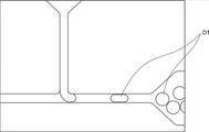
- FIG. 7 is a schematic plan view showing the flow aspect of the fluid in the flow path of the microchannel device according to the embodiment of the present disclosure.
- a droplet D1 is formed by merging two liquids at a T-shaped merging point in a flow path.
- the method for manufacturing a microchannel device includes (1) preparing a first base having a surface having a groove and containing a polymer containing a fluorine atom, and (2) the above.
- the surface of the first base is subjected to plasma treatment in the presence of ammonia gas, and (3) a second surface having a surface for contacting the first base and having solvent resistance.
- the base is prepared, (4) the surface of the second base is subjected to plasma treatment in the presence of ammonia gas, and (5) the first base to which the plasma treatment is performed is performed.
- the surface of the second base to which the plasma treatment has been performed is brought into contact with the surface of the above to form a flow path defined by the first base and the second base. It is preferable to include it.
- each step of the manufacturing method of the microchannel device will be specifically described.
- step (1) a first base having a grooved surface and containing a polymer containing a fluorine atom is prepared.
- the surface having a groove in the first base may be referred to as a “specific surface of the first base”.
- polymer containing a fluorine atom examples include the polymer containing a fluorine atom described in the above-mentioned "first base" section.
- the preferred type of the polymer containing a fluorine atom is the same as the preferred type of the polymer containing a fluorine atom described in the above section “1st base”.
- the specific surface of the first base includes a region that contacts the second base in the step (5) described later and a region that defines the flow path formed in the step (5) described later.
- the specific surface of the first base is subjected to plasma treatment in the step (2) described later, and comes into contact with the second base in the step (5) described later.
- the shape of the groove is not limited.
- the shape of the groove is determined, for example, according to the shape of the target flow path. Examples of the cross-sectional shape of the groove include a quadrangle and a semicircle.
- the method of forming the groove is not limited. Examples of the method for forming the groove include a method using a mold produced by photolithography. For example, many of the channels of known microchannel devices are formed using templates made by photolithography.
- a silicone or a composition containing a silicone material is brought into contact with a mold produced by photolithography and the composition is cured to obtain a first base having a groove.
- the shape of the convex portion of the mold corresponds to the shape of the groove (that is, the concave portion) of the first base portion.
- the shape of the first base is not limited. From the viewpoint of ease of manufacture, the shape of the first base is preferably flat.
- the flat plate-shaped first base has a first main surface and a second main surface on the opposite side of the first main surface.
- the specific surface of the first base portion may be the first main surface or the second main surface.
- Step (2) plasma treatment (hereinafter, may be referred to as “first plasma treatment” in this section) is performed on the specific surface of the first base in the presence of ammonia gas.
- plasma treatment may be performed on the portion in contact with the composition containing the surfactant described later.
- the first plasma treatment forms a functional group such as -NH 3 on a specific surface of the first base.
- a functional group such as -NH 3 groups formed on a specific surface of the first base improves the adhesion of the first base to the second base in the step (5) described later.
- a known plasma processing apparatus may be used.
- the gas used for the first plasma treatment may contain a gas other than ammonia gas as long as it does not deviate from the gist of the present disclosure.
- the flow rate of ammonia gas in the first plasma treatment is preferably 1 sccm to 500 sccm, more preferably 10 sccm to 300 sccm, and particularly preferably 50 sccm to 150 sccm.
- the pressure in the first plasma treatment is preferably 10 Pa to 300 Pa, more preferably 20 Pa to 200 Pa, and particularly preferably 50 Pa to 150 Pa.
- the processing time in the first plasma treatment is preferably 30 seconds to 700 seconds, more preferably 50 seconds to 500 seconds, and particularly preferably 100 seconds to 300 seconds.
- the output in the first plasma treatment is preferably 10 W to 1,000 W, more preferably 20 W to 500 W, and particularly preferably 50 W to 150 W.
- the output is an RF (Radio Frequency) output.
- plasma treatment is performed on a specific surface of the first base in the presence of oxygen gas (hereinafter, in this section). It may include performing "second plasma treatment").
- the second plasma treatment forms functional groups such as -OH group and -COOH group on the specific surface of the first base. Functional groups such as -OH group and -COOH group formed on the specific surface of the first base improve the hydrophilicity of the specific surface of the first base. As a result, the hydrophilicity of the demarcated surface of the first base is improved.
- the gas used for the second plasma treatment may contain a gas other than oxygen gas as long as it does not deviate from the gist of the present disclosure.
- the flow rate of oxygen gas in the second plasma treatment is preferably 1 sccm to 500 sccm, more preferably 10 sccm to 500 sccm, and particularly preferably 50 sccm to 150 sccm.
- the pressure in the second plasma treatment is preferably 10 Pa to 300 Pa, more preferably 20 Pa to 200 Pa, and particularly preferably 50 Pa to 150 Pa.
- the processing time in the second plasma treatment is preferably 10 seconds to 500 seconds, more preferably 20 seconds to 300 seconds, and particularly preferably 50 seconds to 150 seconds.
- the output in the second plasma treatment is preferably 10 W to 1,000 W, more preferably 15 W to 700 W, and particularly preferably 50 W to 500 W.
- the output is an RF (Radio Frequency) output.
- plasma treatment is performed on a specific surface of the first base in the presence of ammonia gas (hereinafter, in this section). It may include performing "third plasma treatment").
- functional groups such as -NH 3 groups are further formed on the specific surface of the first base on which functional groups such as -OH group and -COOH group are formed through the second plasma treatment.
- a series of plasma treatments including the first plasma treatment, the second plasma treatment and the third plasma treatment are carried out by the hydrophilicity of the specific surface of the first base and the first with respect to the second base in the step (5) described later. Improves the adhesion of plasma.
- the gas used for the third plasma treatment may contain a gas other than ammonia gas as long as it does not deviate from the gist of the present disclosure.
- the flow rate of ammonia gas in the third plasma treatment is preferably 1 sccm to 500 sccm, more preferably 10 sccm to 300 sccm, and particularly preferably 50 sccm to 150 sccm.
- the pressure in the third plasma treatment is preferably 10 Pa to 300 Pa, more preferably 20 Pa to 200 Pa, and particularly preferably 50 Pa to 150 Pa.
- the processing time in the third plasma treatment is preferably 30 seconds to 700 seconds, more preferably 50 seconds to 500 seconds, and particularly preferably 100 seconds to 300 seconds.
- the output in the third plasma treatment is preferably 10 W to 1,000 W, more preferably 20 W to 500 W, and particularly preferably 50 W to 150 W.
- the output is an RF (Radio Frequency) output.
- step (3) a second base having a surface for contacting the first base and having solvent resistance is prepared.
- the surface of the second base for contacting the first base may be referred to as a "specific surface of the second base”.
- Examples of the component of the second base include the components described in the above-mentioned “second base (second base)" section.
- the preferred component of the second base is the same as the preferred component of the second base described in the section "Second base (second base)" above.
- the specific surface of the second base is subjected to plasma treatment in the step (4) described later, and comes into contact with the first base in the step (5) described later.
- a groove may be formed on a specific surface of the second base.
- the shape of the groove is not limited. The shape of the groove is determined, for example, according to the shape of the target flow path. Examples of the cross-sectional shape of the groove include a quadrangle and a semicircle. Examples of the method for forming the groove include a method using a mold produced by photolithography described in the above section “Step (1)”.
- the shape of the second base is not limited. From the viewpoint of ease of manufacture, the shape of the second base is preferably flat.
- the flat plate-shaped second base has a first main surface and a second main surface on the opposite side of the first main surface.
- the specific surface of the second base portion may be the first main surface or the second main surface.
- Step (4) plasma treatment (hereinafter, may be referred to as “first plasma treatment” in this section) is performed on the specific surface of the second base in the presence of ammonia gas.
- plasma treatment may be performed on the portion in contact with the composition containing the surfactant described later.
- the preferred conditions for the first plasma treatment are the same as the preferred conditions for the first plasma treatment described in the section "Step (2)" above.
- plasma treatment is performed on a specific surface of the second base in the presence of oxygen gas (hereinafter, in this section). It may include performing "second plasma treatment").
- the preferred conditions for the second plasma treatment are the same as the preferred conditions for the second plasma treatment described in the section “Step (2)” above.
- plasma treatment is performed on a specific surface of the second base in the presence of ammonia gas (hereinafter, in this section). It may include performing "third plasma treatment").
- the preferred conditions for the second plasma treatment are the same as the preferred conditions for the second plasma treatment described in the section “Step (2)” above.
- the step (4) is performed at the same time as the step (2). That is, in the step (4), it is preferable to simultaneously perform plasma treatment on the specific surface of the first base and the specific surface of the second base.
- the step (2) and the step (4) are performed at the same time, the time from the end of the step (2) and the step (4) to the start of the step (5) is shortened, and the first step (5) described later is performed.
- the adhesion between the base of the base and the second base is improved.
- Step (2) and step (4) may be performed simultaneously in, for example, one plasma processing apparatus.
- Step (5) the specific surface of the plasma-treated first base is brought into contact with the specific surface of the plasma-treated second base, and the first base and the second base are brought into contact with each other. Form a flow path defined by.
- the second base is brought into contact with the first base, so that the second base is adhered to the first base.
- the groove of the first base is covered with the second base, so that a space (that is, a flow path) surrounded by the surface of the first base and the surface of the second base is formed.
- the time from the end of the plasma treatment to the contact of the specific surface of the second base subjected to the plasma treatment with the specific surface of the first base subjected to the plasma treatment (hereinafter referred to as).
- waiting time is preferably 0.5 minutes to 10 minutes, more preferably 0.5 minutes to 8 minutes, and 0.5 minutes to 5 minutes. Is preferable.
- the waiting time is calculated from the end of the last plasma treatment.
- step (5) after the specific surface of the second base is brought into contact with the specific surface of the first base, a load is applied to the first base and the second base.
- the load may be determined, for example, depending on the components of the base.
- the load is preferably 50 g / cm 2 to 500 g / cm 2 , and more preferably 80 g / cm 2 to 300 g / cm 2 .
- the step (5) after the specific surface of the second base is brought into contact with the specific surface of the first base under the temperature conditions described later, the first base and the second base are contacted. It is more preferable to apply a load to the base of the.
- the temperature may be determined, for example, depending on the components of the base.
- the temperature is preferably 50 ° C. to 300 ° C., more preferably 80 ° C. to 300 ° C., and particularly preferably 120 ° C. to 300 ° C.
- the temperature in the heating method using a non-contact heating device represents the atmospheric temperature.
- the temperature in the heating method using the contact type heating device represents the temperature of the article in direct contact with the base.
- the method for manufacturing a microchannel device may include circulating a composition containing a surfactant in a channel formed through the above-mentioned step (5).
- a portion of the solid surface defining the flow path ie, the demarcating surface of the first base and the demarcating surface of the second base
- the surfactant can be adsorbed on the surface.
- surfactant examples include the surfactant described in the above section "First base”.
- the preferred type of surfactant is the same as the preferred type of surfactant described in the section "First Base” above.
- the composition may contain two or more surfactants.
- the content of the surfactant in the composition is preferably 0.1% by mass to 20% by mass, more preferably 0.5% by mass to 15% by mass, based on the total mass of the composition. 2, 2% by mass to 8% by mass is particularly preferable.
- the composition containing the surfactant is produced, for example, by mixing the surfactant and the solvent.
- the solvent is preferably a solvent that does not dissolve the first base and the second base.
- the solvent is preferably water.
- the method of distributing the composition into the flow path is not limited.
- the composition may be circulated in the flow path, for example, by a method using a liquid feed pump or a dipping method.
- the liquid feed pump is as described in the section “Manufacturing Droplets” above.
- the composition containing the surfactant is circulated in the flow path by capillary force. ..
- the flow velocity of the composition is preferably 0.1 mm / sec to 1,000 mm / sec, more preferably 0.5 mm / sec to 500 mm / sec. It is particularly preferably 1 mm / sec to 100 mm / sec.
- the flow rate of the composition is 0.1 mm / sec or more, the uniformity of the hydrophilization treatment is improved.
- the flow rate of the composition is 1,000 mm / sec or less, the adsorptivity of the surfactant to the first base and the second base is improved.
- the distribution time of the composition is preferably 0.5 minutes to 120 minutes, more preferably 1 minute to 60 minutes, and particularly preferably 2 minutes to 30 minutes.
- the flow time is represented by the dipping time.
- the amount of the surfactant adsorbed on the solid surface defining the flow path is adjusted, for example, by the content of the surfactant in the composition, the flow velocity of the composition or the flow time of the composition.
- Step (6) may be performed a plurality of times.
- the step (5) may be further performed after the nth step (6) and before the n + 1th step (6). Further, after the step (6), the step (5) may be further performed.
- the step (5) performed at the above time is preferably performed under the conditions of pressurization, heating or both pressurization and heating. The heating conditions and pressurizing conditions in the step (5) are as described in the above-mentioned "step (5)" section.
- step (6) in order to introduce the composition into the flow path, an opening connected to the flow path may be formed in the microchannel device, if necessary. In the step prior to step (6), an opening may be formed in the first base or the second base.
- the microchannel device includes a first base and a second base in contact with the base (see, eg, FIG. 1).
- Step 1 Preparation of photomask
- One side of the blue plate glass (hereinafter referred to as "first side") is covered with a patterned chromium thin film.
- the region of the first surface of the blue plate glass covered by the patterned chromium thin film forms a light-shielding portion of the photomask.
- the region of the first surface of the blue plate glass that is not covered by the patterned chromium thin film forms the transmissive portion of the photomask.
- the photomask includes a T-shaped transmissive portion.
- the line width of the T-shaped transmissive portion is 300 ⁇ m.
- Step 2 Preparation of mold
- a 4-inch silicon wafer (Electronic End Materials Corporation) was washed with acetone and ethanol.
- the washed silicon wafer was dried at 100 ° C. for 10 minutes using a hot plate (HP-1SA, AS ONE Corporation).
- the dried silicon wafer was installed on a spin coater (MS-A150, Mikasa Co., Ltd.) by suction.
- 5 mL of "SU-8 3050" was dropped onto the silicon wafer.
- "SU-8 3050" is a negative photoresist.
- the silicon wafer After removing the air bubbles in the "SU-8 3050" dropped onto the silicon wafer, the silicon wafer was rotated at a rotation speed of 1,300 rpm (revolutions per minute) for 30 seconds. The silicon wafer covered with the thin film of "SU-8 3050" was prebaked at 65 ° C. for 5 minutes and at 95 ° C. for 40 minutes, and then the silicon wafer was cooled to room temperature. The silicon wafer was placed on the mask aligner by suction.
- a photomask chrome thin film is brought into contact with the thin film of "SU-8 3050" formed on a silicon wafer, and the thin film of "SU-8 3050" is exposed to ultraviolet rays of 8.0 mW / cm 2 (wavelength:: 365 nm) was irradiated for 25 seconds.
- the silicon wafer was baked at 65 ° C. for 1 minute and then at 95 ° C. for 15 minutes, and then the silicon wafer was cooled to room temperature.
- a silicon wafer and 10 mL of "SU-8 developer” (KAYAKU Advanced Materials) are placed in a 120 mm diameter glass petri dish, and then a shaker (NR-10, TIETECH Co., Ltd., shaking number: 30 rpm) is used.
- the silicon wafer was hard-baked at 150 ° C. for 20 minutes using a hot plate.
- a mold was obtained by the above procedure.
- the mold includes a silicon wafer and a pattern formed on the silicon wafer using a photoresist.
- Step 3 Preparation of the first base
- the mold was washed with acetone and ethanol and then dried at 100 ° C. for 10 minutes using a hot plate.
- X-71C-8115A fluorine elastomer, "SHIN-ETSU SIFEL”, Shin-Etsu Chemical Co., Ltd.
- X-71C-8115B fluorine elastomer, "SHIN-ETSU SIFEL", on a mold placed in a glass registry
- the cured product was stripped from the mold to give a first base containing a fluoroelastomer. Grooves are formed on the surface of the first base exposed by peeling. The shape of the groove formed in the first base corresponds to the shape of the pattern of the mold.
- the groove depth measured with a laser optical microscope (VK8550, KEYENCE CORPORATION) was in the range of 100 ⁇ m to 105 ⁇ m.
- Step 4 Plasma treatment
- a plate made of fluoroelastomer was prepared. Specifically, X-71C-8115A and X-71C-8115B are mixed at a ratio of 1: 1 (mass ratio), and the obtained mixture is heated at 120 ° C. for 1 hour and cured to form a second base. Obtained.
- the first base and the second base were placed in the chamber of Plasma Etcher CPE-200 (Kai Semiconductor Co., Ltd.). Ammonia gas (NH 3 ) of 100 sccm was flowed into the chamber, and plasma treatment was performed at a pressure of 100 Pa with an RF (Radio Frequency) output of 100 W for 180 seconds.
- the surface to be processed of the first base is the surface on which the groove is formed.
- the surface to be treated of the second base is one side of the second base (that is, the surface of the second base that comes into contact with the first base in step 5 described later).
- Step 5 Laminating After the plasma treatment, the plasma-treated surface of the first base (that is, the surface on which the groove of the first base is formed) and the plasma-treated surface of the second base are bonded to each other, and the obtained microchannel device is used. Then, under a load of 100 g / cm 2 , a heating and pressurizing treatment was performed at a temperature of 150 ° C. for 10 minutes using an oven.
- a T-shaped channel as shown in FIG. 5 is formed between the first base and the second base.
- three openings ie, holes
- Each opening is connected to the end of a T-shaped flow path.
- Examples 2 to 8> A microchannel device was produced by the same procedure as that shown in Example 1 except that the production conditions were changed according to the description in Table 1.
- Example 9 The microchannel device according to Example 9 was produced according to the following procedures shown in Step 1, Step 2, Step 5, and Step 6.
- the microchannel device according to Example 10 was produced according to the following procedures shown in Step 1, Step 2, Step 3, Step 5, and Step 6.
- the microchannel device according to Example 11 was produced according to the following procedures shown in Step 1, Step 2, Step 3, Step 4, Step 5, and Step 6.
- Step 1 Preparation of the first base and the second base
- the first base was prepared by the same procedure as that shown in Steps 1 to 3 of Example 1.
- a second base a plate made of fluoroelastomer was prepared.
- Step 2 First plasma treatment
- the first base and the second base were placed in the chamber of Plasma Etcher CPE-200 (Kai Semiconductor Co., Ltd.).
- Ammonia gas (NH 3 ) was flowed into the chamber at 100 sccm, and plasma treatment was performed at a pressure of 100 Pa at an RF output of 100 W for 180 seconds.
- the surface to be processed of the first base is the surface on which the groove is formed.
- the surface to be treated of the second base is one side of the second base (that is, the surface of the second base that comes into contact with the first base in step 5 described later).
- Step 3 Second plasma treatment
- Oxygen gas (O 2 ) was introduced into the chamber at 100 sccm instead of ammonia gas (NH 3 ), and plasma treatment was performed at a pressure of 100 Pa at an RF output of 300 W for 100 seconds.
- Step 4 Third plasma treatment
- Ammonia gas (NH 3 ) was introduced into the chamber at 100 sccm instead of oxygen gas (O 2 ), and plasma treatment was performed at a pressure of 100 Pa with an RF output of 100 W for 180 seconds.
- Step 5 Laminating
- the plasma treated surface of the first base that is, the surface on which the groove of the first base was formed
- the plasma treated surface of the second base were bonded together.
- a T-shaped channel as shown in FIG. 5 is formed between the first base and the second base.
- the width of the flow path is 300 ⁇ m.
- three openings ie, holes
- Each opening is connected to the end of a T-shaped flow path.
- Step 6 Hydrophilization treatment
- a PFA tube (outer diameter: 1/16 "inch, inner diameter: 0.5 mm) is inserted into each opening, and then a syringe pump (outer diameter: 0.5 mm) is inserted.
- a syringe pump (outer diameter: 0.5 mm) is inserted.
- pure water containing 5% by mass of "Pluronic F127" (BASF) was flowed in the flow path at a flow rate of 3 mL / hour for 5 minutes.
- PFA is a fluororesin called perfluoroalkoxy alkane.
- Example 12 A microchannel device was produced by the same procedure as that shown in Example 11 except that "Pluronic F68" was used instead of "Pluronic F127" in step 6 (hydrophilization treatment).
- a microchannel device was produced by the same procedure as that shown in Example 1 except that the production conditions were changed according to the description in Table 1.
- a microchannel device for contact angle measurement was produced by the same procedure as shown in the corresponding Examples and Comparative Examples, except that the method of hydrophilization treatment was changed and the width of the flow path was changed to 5 mm. did.
- the microchannel device was immersed in the treatment liquid instead of flowing the treatment liquid for the hydrophilization treatment in the flow path.
- the microchannel device for contact angle measurement was cut using a cutter to expose the surface of the first base that defined the channel.
- the surface of the first base that defined the flow path was washed with acetone and ethanol and dried by air blow. 2 ⁇ L of pure water was dropped on the surface of the first base that defined the flow path.
- the contact angle of the droplet 1 second after the contact of pure water with the surface of the first base that defined the flow path was measured using DMs-401 manufactured by Kyowa Interface Science Co., Ltd.
- the contact angle of pure water with respect to the surface of the second base that defined the flow path was measured by the same method as described above. The measurement results are shown in Table 1.
- Ethyl acetate (Wako Pure Chemical Industries, Ltd.) was flowed into the flow path of the third microchannel device at a flow rate of 1 mL / hour for 10 minutes. After passing the organic solvent, the minimum width of the channel of the microchannel device was measured. The solvent resistance was evaluated according to the following criteria based on the rate of change X of the width of the flow path obtained according to the following formula. The evaluation results are shown in Table 1.
- Rate of change in the width of the flow path ([Width of the flow path before the test (300 ⁇ m)]-[Minimum value of the width of the flow path after the test]) / [Width of the flow path before the test] ⁇ 100
- -standard- A The rate of change X of the channel width of all the microchannel devices satisfies -5% ⁇ X ⁇ + 5%.
- B The rate of change X of the channel width of at least one microchannel device satisfies X ⁇ -5% or + 5% ⁇ X.
- the second base was carefully manually peeled from the first base of the microchannel device to obtain a test piece divided into the first base side and a test piece divided into the second base side.
- the surface of the test piece divided into the first base side (hereinafter referred to as “target surface”) exposed by peeling is 300 ⁇ m wide (that is, scanned by a laser) using a laser optical microscope (VK8550, KEYENCE Co., Ltd.). Five regions that differed from each other in terms of distance) were scanned.
- the arithmetic mean roughness Ra of the target surface was calculated. The larger the value of Ra, the higher the adhesiveness, that is, the adhesion between the first base and the second base.
- the components listed in the "base” section of Table 1 indicate the components of the first base and the components of the second base.
- Table 1 shows that the solvent resistance and the adhesiveness of the microchannel devices in Examples 1 to 12 are superior to the solvent resistance and the adhesiveness of the microchannel devices in Comparative Examples 1 to 5. show.
- Silicone oil (KF96-1CS, Shin-Etsu Chemical Co., Ltd.) was introduced at a flow rate of 10 mL / hour, and pure water was introduced into the flow path 31 from the opening connected to the second flow path portion 31b at a flow rate of 3 mL / hour. By the introduction, uniform water droplets in oil were obtained at the confluence point 31A.
- oil droplets in water were produced by the following procedure.
- a syringe pump PLD4400, HARVARD
- 10 mL of pure water containing 1% by mass of polyvinyl alcohol (Merck) into the flow path 31 from the opening (not shown) connected to the first flow path 31a.
- silicone oil KF96-1CS, Shin-Etsu Chemical Co., Ltd.
- a uniform oil droplet in water was obtained at point 31A (see, for example, FIG. 7).
Landscapes
- Chemical & Material Sciences (AREA)
- Chemical Kinetics & Catalysis (AREA)
- Organic Chemistry (AREA)
- Engineering & Computer Science (AREA)
- Dispersion Chemistry (AREA)
- Manufacturing & Machinery (AREA)
- Microelectronics & Electronic Packaging (AREA)
- Polymers & Plastics (AREA)
- Medicinal Chemistry (AREA)
- Health & Medical Sciences (AREA)
- Analytical Chemistry (AREA)
- Computer Hardware Design (AREA)
- Physical Or Chemical Processes And Apparatus (AREA)
Abstract
Description
本開示の他の一態様は、優れた耐溶剤性及び貼合性を有するマイクロ流路デバイスを用いた液滴の製造方法を提供することを目的とする。
本開示の他の一態様は、優れた耐溶剤性及び貼合性を有するマイクロ流路デバイスを用いた気泡の製造方法を提供することを目的とする。
本開示の他の一態様は、優れた耐溶剤性及び貼合性を有するマイクロ流路デバイスを用いたマイクロカプセルの製造方法を提供することを目的とする。
本開示の他の一態様は、優れた耐溶剤性及び貼合性を有するマイクロ流路デバイスを用いた多重エマルションの製造方法を提供することを目的とする。
本開示の他の一態様は、優れた耐溶剤性及び貼合性を有するマイクロ流路デバイスを用いた気泡を内包する液滴の製造方法の提供することを目的とする。
本開示の他の一態様は、優れた耐溶剤性及び貼合性を有するマイクロ流路デバイスの製造方法を提供することを目的とする。
<1> 流路を画定する画定面を有し、フッ素原子を含む重合体を含む第1の基部と、上記第1の基部の上記画定面とともに上記流路を画定する画定面を有し、耐溶剤性を有し、上記第1の基部に接触する第2の基部と、を含み、上記第1の基部から上記第2の基部を剥離することによって露出した上記第1の基部の表面の算術平均粗さRaが、1μm以上である、マイクロ流路デバイス。
<2> 上記第2の基部が、フッ素原子を含む重合体、ガラス及びステンレス鋼からなる群より選択される少なくとも1種を含む、<1>に記載のマイクロ流路デバイス。
<3> 上記第1の基部の上記画定面に対する水の接触角が、90°以上であり、上記第2の基部の上記画定面に対する水の接触角が、90°以上である、<1>又は<2>に記載のマイクロ流路デバイス。
<4> 上記第1の基部の上記画定面が、界面活性剤を吸着した領域を含み、上記第1の基部の上記画定面において上記界面活性剤を吸着した上記領域に対する水の接触角が、60°以下であり、上記第2の基部の上記画定面が、界面活性剤を吸着した領域を含み、上記第2の基部の上記画定面のうち上記界面活性剤を吸着した上記領域に対する水の接触角が、60°以下である、<1>又は<2>に記載のマイクロ流路デバイス。
<5> 上記界面活性剤が、アルキレンオキシド重合体である、<4>に記載のマイクロ流路デバイス。
<6> 上記界面活性剤が、エチレンオキシド-プロピレンオキシド共重合体である、<4>に記載のマイクロ流路デバイス。
<7> 上記第1の基部の上記画定面が、界面活性剤を吸着していない領域を更に含み、上記第2の基部の上記画定面が、界面活性剤を吸着していない領域を更に含む、<4>~<6>のいずれか1つに記載のマイクロ流路デバイス。
<8> 上記流路が、第1の流路部と、上記第1の流路部に合流する第2の流路部と、上記第1の流路部と上記第2の流路部との合流点に接続する第3の流路部と、を含む、<1>~<7>のいずれか1つに記載のマイクロ流路デバイス。
<9> 上記流路が、第1の流路部と、上記第1の流路部に合流する第2の流路部と、上記第1の流路部と上記第2の流路部との合流点に接続する第3の流路部と、上記第3の流路部に合流する第4の流路部と、上記第3の流路部と上記第4の流路部との合流点に接続する第5の流路部と、を含む、<1>~<7>のいずれか1つに記載のマイクロ流路デバイス。
<10> 液滴を製造するために用いられる、<1>~<9>のいずれか1つに記載のマイクロ流路デバイス。
<11> 気泡を製造するために用いられる、<1>~<9>のいずれか1つに記載のマイクロ流路デバイス。
<12> マイクロカプセルを製造するために用いられる、<1>~<9>のいずれか1つに記載のマイクロ流路デバイス。
<13> 多重エマルションを製造するために用いられる、<1>~<9>のいずれか1つに記載のマイクロ流路デバイス。
<14> 気泡を内包する液滴を製造するために用いられる、<1>~<9>のいずれか1つに記載のマイクロ流路デバイス。
<15> <1>~<9>のいずれか1つに記載のマイクロ流路デバイスを用いる液滴の製造方法であって、マイクロ流路デバイスの流路内で油を含む液体と水を含む液体とを合流させて、液滴を得ることを含む、液滴の製造方法。
<16> <1>~<9>のいずれか1つに記載のマイクロ流路デバイスを用いる気泡の製造方法であって、マイクロ流路デバイスの流路内で液体と気体とを合流させて、気泡を得ることを含む、気泡の製造方法。
<17> <1>~<9>のいずれか1つに記載のマイクロ流路デバイスを用いるマイクロカプセルの製造方法であって、マイクロ流路デバイスの流路内で油を含む液体と水を含む液体とを合流させて、マイクロカプセルを得ることを含む、マイクロカプセルの製造方法。
<18> <1>~<9>のいずれか1つに記載のマイクロ流路デバイスを用いる多重エマルションの製造方法であって、マイクロ流路デバイスの流路内で少なくとも3種の液体を合流させて、多重エマルションを得ることを含む、多重エマルションの製造方法。
<19> <1>~<9>のいずれか1つに記載のマイクロ流路デバイスを用いる気泡を内包する液滴の製造方法であって、マイクロ流路デバイスの流路内で、気体と、油を含む液体と、水を含む液体とを合流させて、気泡を内包する液滴を得ることを含む、気泡を内包する液滴の製造方法。
<20> 溝を有する面を有し、フッ素原子を含む重合体を含む第1の基部を準備することと、上記第1の基部の上記面に対して、アンモニアガスの存在下でプラズマ処理を行うことと、上記第1の基部に接触するための面を有し、耐溶剤性を有する第2の基部を準備することと、上記第2の基部の上記面に対して、アンモニアガスの存在下でプラズマ処理を行うことと、上記プラズマ処理が行われた上記第1の基部の上記面に、上記プラズマ処理が行われた上記第2の基部の上記面を接触させて、上記第1の基部と上記第2の基部とによって画定される流路を形成することと、を含む、マイクロ流路デバイスの製造方法。
本開示の他の一態様によれば、優れた耐溶剤性及び貼合性を有するマイクロ流路デバイスを用いた液滴の製造方法が提供される。
本開示の他の一態様によれば、優れた耐溶剤性及び貼合性を有するマイクロ流路デバイスを用いた気泡の製造方法が提供される。
本開示の他の一態様によれば、優れた耐溶剤性及び貼合性を有するマイクロ流路デバイスを用いたマイクロカプセルの製造方法が提供される。
本開示の他の一態様によれば、優れた耐溶剤性及び貼合性を有するマイクロ流路デバイスを用いた多重エマルションの製造方法が提供される。
本開示の他の一態様によれば、優れた耐溶剤性及び貼合性を有するマイクロ流路デバイスを用いた気泡を内包する液滴の製造方法が提供される。
本開示の他の一態様によれば、優れた耐溶剤性及び貼合性を有するマイクロ流路デバイスの製造方法が提供される。
本開示の一実施形態に係るマイクロ流路デバイスは、流路を画定する画定面を有し、フッ素原子を含む重合体を含む第1の基部と、上記第1の基部の上記画定面とともに上記流路を画定する画定面を有し、耐溶剤性を有し、上記第1の基部に接触する第2の基部と、を含む。上記した実施形態において、第1の基部から第2の基部を剥離することによって露出した上記第1の基部の表面の算術平均粗さRaは、1μm以上である。上記した実施形態によれば、優れた耐溶剤性及び貼合性を有するマイクロ流路デバイスが提供される。本開示において、「貼合性」とは、第1の基部と第2の基部との密着性(接着性ともいう。)を表す。本開示において、「耐溶剤性」とは、有機溶剤に対する抵抗性を意味する。
本開示の一実施形態に係るマイクロ流路デバイスにおいて、第1の基部から第2の基部を剥離することによって露出した上記第1の基部の表面(すなわち、露出面)の算術平均粗さRaは、1μm以上である。貼合性の向上の観点から、露出面の算術平均粗さRaは、2μm以上であることが好ましく、3μm以上であることがより好ましく、5μm以上であることが特に好ましい。貼合性の観点において、露出面の算術平均粗さRaの上限は制限されない。露出面の算術平均粗さRaの上限は、例えば、300μm、500μm又は1000μmであってもよい。露出面の算術平均粗さRaは、1μm~1000μmであることが好ましく、2μm~500μmであることがより好ましく、3μm~300μmであることが特に好ましい。
本開示の一実施形態に係るマイクロ流路デバイスは、流路を画定する画定面を有し、フッ素原子を含む重合体を含む第1の基部を含む。フッ素原子を含む重合体を含む第1の基部は、マイクロ流路デバイスの耐溶剤性を向上させる。以下、第1の基部について具体的に説明する。
・一次イオン:Bi3 +
・測定モード:Bunching Mode
・測定面積:300μm(面分解能:128×128pixel)
・積算数:16回
・極性:positive
本開示の一実施形態に係るマイクロ流路デバイスは、第1の基部に接触する第2の基部を含む。第2の基部は、第1の基部の画定面とともに流路を画定する画定面を有する。第2の基部の画定面によって画定される流路は、第1の基部の画定面によって画定される流路と同じである。すなわち、第1の基部及び第2の基部を含むマイクロ流路デバイスにおける流路は、第1の基部と第2の基部との間に形成される。第2の基部は、耐溶剤性を有する。耐溶剤性を有する第2の基部は、マイクロ流路デバイスの耐溶剤性を向上させる。以下、第2の基部について具体的に説明する。
式:試験片の質量の変化率=([試験前の試験片の質量]-[試験後の試験片の質量])/[試験前の試験片の質量]×100
本開示の一実施形態に係るマイクロ流路デバイスの流路は、第1の基部の画定面及び第2の基部の画定面によって画定されている。
本開示の一実施形態に係るマイクロ流路デバイスの用途は制限されない。本開示の一実施形態に係るマイクロ流路デバイスは、例えば、混合、分離、分析又は反応に利用されてもよい。本開示の一実施形態に係るマイクロ流路デバイスは、油を含む液体を用いる技術に利用されることが好ましい。本開示の一実施形態に係るマイクロ流路デバイスの用途の具体例を以下に示す。ただし、本開示の一実施形態に係るマイクロ流路デバイスの用途は、以下に示す具体例に制限されるものではない。
本開示の一実施形態に係るマイクロ流路デバイスは、液滴を製造するために用いられることが好ましい。液滴としては、例えば、油滴及び水滴が挙げられる。油滴としては、例えば、水中に分散した油滴が挙げられる。油滴は、例えば、水又は空気を内包してもよい。水滴としては、例えば、油中に分散した水滴が挙げられる。水滴は、例えば、油又は空気を内包してもよい。液滴は、例えば、マイクロ流路デバイスの流路内で油を含む液体と水を含む液体とを合流させることによって製造される。液滴は、例えば、公知のマイクロ流路デバイスを用いる液滴の製造方法を参照して製造されてもよい。以下、本開示の一実施形態に係るマイクロ流路デバイスを用いる液滴の製造方法について説明する。
本開示の一実施形態に係るマイクロ流路デバイスは、気泡を製造するために用いられることが好ましい。気泡としては、例えば、油中に分散した気泡又は水中に分散した気泡が挙げられる。気泡は、例えば、マイクロ流路デバイスの流路内で液体と気体とを合流させることによって製造される。気泡は、例えば、公知のマイクロ流路デバイスを用いる気泡の製造方法を参照して製造されてもよい。以下、本開示の一実施形態に係るマイクロ流路デバイスを用いる気体の製造方法について説明する。
本開示の一実施形態に係るマイクロ流路デバイスは、マイクロカプセルを製造するために用いられることが好ましい。マイクロカプセルの種類は制限されない。マイクロカプセルは、例えば、多重マイクロカプセルであってもよい。マイクロカプセルは、例えば、芯物質と、上記芯物質を内包する外殻と、を含む。
本開示の一実施形態に係るマイクロ流路デバイスは、多重エマルションを製造するために用いられることが好ましい。多重エマルションとしては、例えば、W/O/W型のエマルション及びO/W/O型のエマルションが挙げられる。W/O/W型のエマルションは、水中に分散した、水を内包する油滴を含む系である。O/W/O型のエマルションは、油中に分散した、油を内包する水滴を含む系である。多重エマルションにおいて、分散媒中に分散している液滴に含まれる層の数は、例えば、2層又は3層以上であってもよい。分散媒は、連続相とも称される。
本開示の一実施形態に係るマイクロ流路デバイスは、気泡を内包する液滴を製造するために用いられることが好ましい。気泡を内包する液滴としては、液体中に分散した、気泡を内包する液滴が挙げられる。分散媒として用いられる液体としては、例えば、油及び水が挙げられる。液滴としては、例えば、油滴及び水滴が挙げられる。液滴は、油滴であることが好ましい。液滴が油滴である場合、分散媒として用いられる液体は水であることが好ましい。気泡を内包する液滴は、例えば、マイクロ流路デバイスの流路内で、気体と、油を含む液体と、水を含む液体とを合流させることによって製造される。気泡を内包する液滴は、例えば、公知のマイクロ流路デバイスを用いる油滴の製造方法を参照して製造されてもよい。以下、本開示の一実施形態に係るマイクロ流路デバイスを用いる気泡を内包する液滴の製造方法について説明する。
本開示の一実施形態に係るマイクロ流路デバイスは、上記した用途以外の用途に用いられてもよい。本開示の一実施形態に係るマイクロ流路デバイスは、例えば、ヤヌス粒子及び多重構造の一部が固体である部分的マイクロカプセルといった多層構造を有する粒子を製造するために用いられてもよい。
液滴の形成について、図7を参照して説明する。図7は、本開示のある実施形態に係るマイクロ流路デバイスの流路における流体の流動様相を示す概略平面図である。図7に示されるように、例えば、流路内のT字型の合流点で2つの液体が合流することで、液滴D1が形成される。
本開示の一実施形態に係るマイクロ流路デバイスの製造方法は、(1)溝を有する面を有し、フッ素原子を含む重合体を含む第1の基部を準備することと、(2)上記第1の基部の上記面に対して、アンモニアガスの存在下でプラズマ処理を行うことと、(3)上記第1の基部に接触するための面を有し、耐溶剤性を有する第2の基部を準備することと、(4)上記第2の基部の上記面に対して、アンモニアガスの存在下でプラズマ処理を行うことと、(5)上記プラズマ処理が行われた上記第1の基部の上記面に、上記プラズマ処理が行われた上記第2の基部の上記面を接触させて、上記第1の基部と上記第2の基部とによって画定される流路を形成することと、を含むことが好ましい。以下、マイクロ流路デバイスの製造方法の各段階について具体的に説明する。
工程(1)では、溝を有する面を有し、フッ素原子を含む重合体を含む第1の基部を準備する。以下、第1の基部における溝を有する面を「第1の基部の特定面」という場合がある。
工程(2)では、第1の基部の特定面に対して、アンモニアガスの存在下でプラズマ処理(以下、本項において「第1のプラズマ処理」という場合がある。)を行う。工程(2)では、必要に応じて、後述する界面活性剤を含む組成物に接触する部分に対してもプラズマ処理が行われてもよい。第1のプラズマ処理は、第1の基部の特定面に-NH3基といった官能基を形成する。第1の基部の特定面に形成された-NH3基といった官能基は、後述する工程(5)において第2の基部に対する第1の基部の密着性を向上させる。プラズマ処理では、例えば、公知のプラズマ処理装置が用いられてもよい。第1のプラズマ処理に用いられるガスは、本開示の趣旨を逸脱しない限り、アンモニアガス以外のガスを含んでもよい。
工程(3)では、第1の基部に接触するための面を有し、耐溶剤性を有する第2の基部を準備する。以下、第2の基部における第1の基部に接触するための面を「第2の基部の特定面」という場合がある。
工程(4)では、第2の基部の特定面に対して、アンモニアガスの存在下でプラズマ処理(以下、本項において「第1のプラズマ処理」という場合がある。)を行う。工程(4)では、必要に応じて、後述する界面活性剤を含む組成物に接触する部分に対してもプラズマ処理が行われてもよい。第1のプラズマ処理の好ましい条件は、上記「工程(2)」の項で説明した第1のプラズマ処理の好ましい条件と同じである。
工程(5)では、プラズマ処理が行われた第1の基部の特定面に、プラズマ処理が行われた第2の基部の特定面を接触させて、上記第1の基部と上記第2の基部とによって画定される流路を形成する。プラズマ処理の後、第1の基部に第2の基部を接触させることで、第1の基部に第2の基部が接着する。工程(5)では、第1の基部の溝が第2の基部によって覆われることで、第1の基部の表面及び第2の基部の表面に囲まれた空間(すなわち、流路)が形成される。
本開示の一実施形態に係るマイクロ流路デバイスの製造方法は、上記した工程(5)を経て形成された流路内に界面活性剤を含む組成物を流通させることを含んでもよい。流路内に界面活性剤を含む組成物を流通させることで、流路を画定する固体表面(すなわち、第1の基部の画定面及び第2の基部の画定面)の組成物に接触する部分に界面活性剤を吸着させることができる。
以下の手順に従って、マイクロ流路デバイスを作製した。マイクロ流路デバイスは、第1の基部と、上記基部に接触する第2の基部と、を含む(例えば、図1参照)。
青板ガラスと、パターン状のクロム薄膜と、を含むフォトマスク(株式会社システムアドバンス)を準備した。青板ガラスの片面(以下、「第1の面」という。)は、パターン状のクロム薄膜によって覆われている。青板ガラスの第1の面のうちパターン状のクロム薄膜によって覆われた領域は、フォトマスクの遮光部を形成する。青板ガラスの第1の面のうちパターン状のクロム薄膜によって覆われていない領域は、フォトマスクの透過部を形成する。フォトマスクは、T字型の透過部を含む。T字型の透過部の線幅は、300μmである。
4インチのシリコンウェーハ(株式会社エレクトロニクスエンドマテリアルズコーポレーション)を、アセトン及びエタノールを用いて洗浄した。洗浄したシリコンウェーハを、ホットプレート(HP-1SA、アズワン株式会社)を用いて100℃で10分間乾燥した。乾燥したシリコンウェーハを、吸引によってスピンコータ(MS-A150、ミカサ株式会社)に設置した。シリコンウェーハの上に5mLの「SU-8 3050」(KAYAKU Advanced Materials社)を滴下した。「SU-8 3050」は、ネガ型のフォトレジストである。シリコンウェーハの上に滴下された「SU-8 3050」内の気泡を除去した後、シリコンウェーハを1,300rpm(revolutions per minute)の回転数で30秒間回転させた。「SU-8 3050」の薄膜によって覆われたシリコンウェーハに対して、65℃で5分間、そして、95℃で40分間のプリベークを行った後、シリコンウェーハを室温に冷却した。シリコンウェーハを、吸引によってマスクアライナーに設置した。シリコンウェーハの上に形成された「SU-8 3050」の薄膜にフォトマスクのクロム薄膜を接触させて、「SU-8 3050」の薄膜に対して、8.0mW/cm2の紫外線(波長:365nm)を25秒間照射した。シリコンウェーハに対して、65℃で1分間、そして、95℃で15分間のベークを行った後、シリコンウェーハを室温に冷却した。120mm径のガラスシャーレに、シリコンウェーハ、そして、10mLの「SU-8 developer」(KAYAKU Advanced Materials社)を入れた後、振とう機(NR-10、タイテック株式会社、振とう数:30rpm)を用いて10分間現像を行った。シリコンウェーハに残留した「SU-8 3050」及び「SU-8 developer」をイソプロピルアルコール(富士フイルム和光純薬株式会社)を用いて洗浄した。シリコンウェーハに対して、ホットプレートを用いて150℃で20分間のハードベークを行った。以上の手順によって鋳型を得た。鋳型は、シリコンウェーハと、上記シリコンウェーハの上にフォトレジストを用いて形成されたパターンと、を含む。
鋳型を、アセトン及びエタノールを用いて洗浄した後、ホットプレートを用いて100℃で10分間乾燥した。ガラスシャーレ内に配置した鋳型の上に、X-71C-8115A(フッ素エラストマー、「SHIN-ETSU SIFEL」、信越化学工業株式会社)とX-71C-8115B(フッ素エラストマー、「SHIN-ETSU SIFEL」、信越化学工業株式会社)とを1:1(質量比)で混合した組成物を配置した。脱気の後、組成物を、ホットプレートを用いて120℃で1時間加熱することで硬化させた。硬化物を鋳型から剥離することで、フッ素エラストマーを含む第1の基部を得た。剥離によって露出した第1の基部の表面には溝が形成されている。第1の基部に形成された溝の形状は、鋳型のパターンの形状に対応している。レーザー光学顕微鏡(VK8550、株式会社キーエンス)を用いて測定した溝の深さは、100μm~105μmの範囲内であった。
第2の基部として、フッ素エラストマー製の板を準備した。具体的に、X-71C-8115AとX-71C-8115Bとを1:1(質量比)で混合し、得られた混合物を120℃で1時間加熱し硬化することで、第2の基部を得た。第1の基部及び第2の基部をプラズマエッチャーCPE-200(株式会社魁半導体)のチャンバー内に配置した。チャンバー内に100sccmのアンモニアガス(NH3)を流入させ、100Paの圧力にて、100WのRF(Radio Frequency)出力で180秒間のプラズマ処理を行った。第1の基部の処理対象面は、溝が形成された面である。第2の基部の処理対象面は、第2の基部の片面(すなわち、後述する工程5において第1の基部に接触する第2の基部の表面)である。
プラズマ処理後、第1の基部のプラズマ処理面(すなわち、第1の基部の溝が形成された面)と第2の基部のプラズマ処理面とを貼り合わせ、得られたマイクロ流路デバイスに対して、100g/cm2の荷重をかけた状態でオーブンを用いて150℃の温度で10分間の加熱加圧処理を行った。
表1の記載に従って製造条件を変更したこと以外は、実施例1に示す手順と同じ手順によって、マイクロ流路デバイスを作製した。
以下の工程1、工程2、工程5及び工程6に示す手順に従って、実施例9に係るマイクロ流路デバイスを作製した。以下の工程1、工程2、工程3、工程5及び工程6に示す手順に従って、実施例10に係るマイクロ流路デバイスを作製した。以下の工程1、工程2、工程3、工程4、工程5及び工程6に示す手順に従って、実施例11に係るマイクロ流路デバイスを作製した。
実施例1の工程1~工程3に示す手順と同じ手順によって、第1の基部を作製した。第2の基部として、フッ素エラストマー製の板を準備した。
第1の基部及び第2の基部をプラズマエッチャーCPE-200(株式会社魁半導体)のチャンバー内に配置した。チャンバー内にアンモニアガス(NH3)を100sccmで流入させ、100Paの圧力にて、100WのRF出力で180秒間のプラズマ処理を行った。第1の基部の処理対象面は、溝が形成された面である。第2の基部の処理対象面は、第2の基部の片面(すなわち、後述する工程5において第1の基部に接触する第2の基部の表面)である。
アンモニアガス(NH3)に代えて酸素ガス(O2)をチャンバー内に100sccmで流入させ、100Paの圧力にて300WのRF出力で100秒間のプラズマ処理を行った。
酸素ガス(O2)に代えてアンモニアガス(NH3)を100sccmでチャンバー内に流入させ、100Paの圧力にて100WのRF出力で180秒間のプラズマ処理を行った。
一連のプラズマ処理の後に、第1の基部のプラズマ処理面(すなわち、第1の基部の溝が形成された面)と第2の基部のプラズマ処理面とを貼り合わせた。得られたマイクロ流路デバイスにおいて、第1の基部と第2の基部との間には図5に示されるようなT字型の流路が形成されている。流路の幅は、300μmである。1.5mm径の生検トレパン(貝印株式会社)を用いて、マイクロ流路デバイスの第1の基部に3つの開口部(すなわち、穴)を形成した。各開口部は、T字型の流路の末端に接続している。
マイクロ流路デバイスに対して100g/cm2の荷重をかけた状態で、各開口部に、PFAチューブ(外径:1/16”インチ、内径:0.5mm)を挿入した後、シリンジポンプ(PHD4400、HARVARD社)を用いて、流路内に5質量%の「Pluronic F127」(BASF社)を含む純水を3mL/時間の流量で5分間流した。PFAは、パーフルオロアルコキシアルカンと称されるフッ素樹脂である。流路内の液を圧縮空気により押し出した後、オーブンを用いて150℃の温度で10分間加熱加圧処理を行った。オーブンから取り出したマイクロ流路デバイスを冷却した。次に、シリンジポンプ(PHD4400、HARVARD社)を用いて、流路内に5質量%の「Pluronic F127」(BASF社)を含む純水を3mL/時間の流量で5分間流した。流路内に「Pluronic F127」を流すことで、流路に面する第1の基部の表面及び第2の基部の表面に対して親水化処理を行った。
工程6(親水化処理)において、「Pluronic F127」にかえて、「Pluronic F68」を用いたこと以外は、実施例11に示す手順と同じ手順によって、マイクロ流路デバイスを作製した。
表1の記載に従って製造条件を変更したこと以外は、実施例1に示す手順と同じ手順によって、マイクロ流路デバイスを作製した。
(接触角)
親水化処理の方法を変更したことと、流路の幅を5mmに変更したこと以外は、対応する実施例及び比較例に示す手順と同じ手順によって、接触角測定用のマイクロ流路デバイスを作製した。親水化処理では、流路内に親水化処理用の処理液を流すことに代えてマイクロ流路デバイスを処理液に浸漬させた。接触角測定用のマイクロ流路デバイスをカッターを用いて割断し、流路を画定していた第1の基部の面を露出させた。流路を画定していた第1の基部の面をアセトン及びエタノールを用いて洗浄し、エアブローによって乾燥させた。流路を画定していた第1の基部の面に2μLの純水を滴下した。流路を画定していた第1の基部の面への純水の接触から1秒後の液滴の接触角を、協和界面科学株式会社製のDMs-401を用いて測定した。上記した方法と同じ方法によって、流路を画定していた第2の基部の面に対する純水の接触角を測定した。測定結果を表1に示す。
(耐溶剤性)
耐溶剤性を評価するため、実施例及び比較例のそれぞれにおいて3つのマイクロ流路デバイスを準備した。3つのマイクロ流路デバイスの流路内に、以下に示す3種の溶剤をそれぞれ流した。メチルエチルケトン(富士フイルム和光純薬株式会社)を1つ目のマイクロ流路デバイスの流路内に1mL/時間の流量で10分間流した。トルエン(富士フイルム和光純薬株式会社)を2つ目のマイクロ流路デバイスの流路内に1mL/時間の流量で10分間流した。酢酸エチル(富士フイルム和光純薬株式会社)を3つ目のマイクロ流路デバイスの流路内に1mL/時間の流量で10分間流した。有機溶剤の通液後に、マイクロ流路デバイスの流路の幅の最小値を測定した。以下の式に従って求めた流路の幅の変化率Xに基づき、以下の基準に従って耐溶剤性を評価した。評価結果を表1に示す。
A:全てのマイクロ流路デバイスの流路の幅の変化率Xが、-5%≦X≦+5%を満たす。
B:少なくとも1つのマイクロ流路デバイスの流路の幅の変化率Xが、X<-5%又は+5%<Xを満たす。
マイクロ流路デバイスの第1の基部から第2の基部を手作業で慎重に剥離し、第1の基部側に分かれた試験片及び第2の基部側に分かれた試験片を得た。剥離によって露出した、第1の基部側に分かれた試験片の表面(以下、「対象面」という。)を、レーザー光学顕微鏡(VK8550、株式会社キーエンス)を用いて300μm幅(すなわち、レーザーの走査距離)で互いに異なる5つの領域を走査した。対象面の算術平均粗さRaを算出した。Raの値が大きいほど、貼合性、すなわち、第1の基部と第2の基部との密着性が高いことを示す。

実施例1で作製したマイクロ流路デバイスを用いて、以下の手順によって油中水滴を製造した。以下、試験の具体的な手順について、図5を参照して説明する。シリンジポンプ(PHD4400、HARVARD社)を用いて、第1の流路部31aに接続した開口部(不図示)より流路31内へ0.5質量%のKF6017(信越化学工業株式会社)を含むシリコーンオイル(KF96-1CS、信越化学工業株式会社)を10mL/時間の流量で導入し、そして、第2の流路部31bに接続した開口部より流路31内へ純水を3mL/時間で導入することで、合流点31Aで均一な油中水滴が得られた。
20:第2の基部
30、31、32:流路
31a、32a:第1の流路部
31b、32b:第2の流路部
31c、32c:第3の流路部
32d:第4の流路部
32e:第5の流路部
30A、30B、31A、32A、32B:合流点
40、41、42、43:開口部
100:マイクロ流路デバイス
D1:液滴
Claims (20)
- 流路を画定する画定面を有し、フッ素原子を含む重合体を含む第1の基部と、
前記第1の基部の前記画定面とともに前記流路を画定する画定面を有し、耐溶剤性を有し、前記第1の基部に接触する第2の基部と、を含み、
前記第1の基部から前記第2の基部を剥離することによって露出した前記第1の基部の表面の算術平均粗さRaが、1μm以上である、
マイクロ流路デバイス。 - 前記第2の基部が、フッ素原子を含む重合体、ガラス及びステンレス鋼からなる群より選択される少なくとも1種を含む、請求項1に記載のマイクロ流路デバイス。
- 前記第1の基部の前記画定面に対する水の接触角が、90°以上であり、前記第2の基部の前記画定面に対する水の接触角が、90°以上である、請求項1又は請求項2に記載のマイクロ流路デバイス。
- 前記第1の基部の前記画定面が、界面活性剤を吸着した領域を含み、前記第1の基部の前記画定面において前記界面活性剤を吸着した前記領域に対する水の接触角が、60°以下であり、前記第2の基部の前記画定面が、界面活性剤を吸着した領域を含み、前記第2の基部の前記画定面のうち前記界面活性剤を吸着した前記領域に対する水の接触角が、60°以下である、請求項1又は請求項2に記載のマイクロ流路デバイス。
- 前記界面活性剤が、アルキレンオキシド重合体である、請求項4に記載のマイクロ流路デバイス。
- 前記界面活性剤が、エチレンオキシド-プロピレンオキシド共重合体である、請求項4に記載のマイクロ流路デバイス。
- 前記第1の基部の前記画定面が、界面活性剤を吸着していない領域を更に含み、前記第2の基部の前記画定面が、界面活性剤を吸着していない領域を更に含む、請求項4~請求項6のいずれか1項に記載のマイクロ流路デバイス。
- 前記流路が、第1の流路部と、前記第1の流路部に合流する第2の流路部と、前記第1の流路部と前記第2の流路部との合流点に接続する第3の流路部と、を含む、請求項1~請求項7のいずれか1項に記載のマイクロ流路デバイス。
- 前記流路が、第1の流路部と、前記第1の流路部に合流する第2の流路部と、前記第1の流路部と前記第2の流路部との合流点に接続する第3の流路部と、前記第3の流路部に合流する第4の流路部と、前記第3の流路部と前記第4の流路部との合流点に接続する第5の流路部と、を含む、請求項1~請求項7のいずれか1項に記載のマイクロ流路デバイス。
- 液滴を製造するために用いられる、請求項1~請求項9のいずれか1項に記載のマイクロ流路デバイス。
- 気泡を製造するために用いられる、請求項1~請求項9のいずれか1項に記載のマイクロ流路デバイス。
- マイクロカプセルを製造するために用いられる、請求項1~請求項9のいずれか1項に記載のマイクロ流路デバイス。
- 多重エマルションを製造するために用いられる、請求項1~請求項9のいずれか1項に記載のマイクロ流路デバイス。
- 気泡を内包する液滴を製造するために用いられる、請求項1~請求項9のいずれか1項に記載のマイクロ流路デバイス。
- 請求項1~請求項9のいずれか1項に記載のマイクロ流路デバイスを用いる液滴の製造方法であって、マイクロ流路デバイスの流路内で油を含む液体と水を含む液体とを合流させて、液滴を得ることを含む、液滴の製造方法。
- 請求項1~請求項9のいずれか1項に記載のマイクロ流路デバイスを用いる気泡の製造方法であって、マイクロ流路デバイスの流路内で液体と気体とを合流させて、気泡を得ることを含む、気泡の製造方法。
- 請求項1~請求項9のいずれか1項に記載のマイクロ流路デバイスを用いるマイクロカプセルの製造方法であって、マイクロ流路デバイスの流路内で油を含む液体と水を含む液体とを合流させて、マイクロカプセルを得ることを含む、マイクロカプセルの製造方法。
- 請求項1~請求項9のいずれか1項に記載のマイクロ流路デバイスを用いる多重エマルションの製造方法であって、マイクロ流路デバイスの流路内で少なくとも3種の液体を合流させて、多重エマルションを得ることを含む、多重エマルションの製造方法。
- 請求項1~請求項9のいずれか1項に記載のマイクロ流路デバイスを用いる気泡を内包する液滴の製造方法であって、マイクロ流路デバイスの流路内で、気体と、油を含む液体と、水を含む液体とを合流させて、気泡を内包する液滴を得ることを含む、気泡を内包する液滴の製造方法。
- 溝を有する面を有し、フッ素原子を含む重合体を含む第1の基部を準備することと、
前記第1の基部の前記面に対して、アンモニアガスの存在下でプラズマ処理を行うことと、
前記第1の基部に接触するための面を有し、耐溶剤性を有する第2の基部を準備することと、
前記第2の基部の前記面に対して、アンモニアガスの存在下でプラズマ処理を行うことと、
前記プラズマ処理が行われた前記第1の基部の前記面に、前記プラズマ処理が行われた前記第2の基部の前記面を接触させて、前記第1の基部と前記第2の基部とによって画定される流路を形成することと、を含む、
マイクロ流路デバイスの製造方法。
Priority Applications (4)
| Application Number | Priority Date | Filing Date | Title |
|---|---|---|---|
| EP21860937.8A EP4206119A4 (en) | 2020-08-25 | 2021-06-18 | MICROCHANNEL DEVICE, DROPLET PRODUCTION PROCESS, MICROCAPSULE PRODUCTION PROCESS, MULTIPLE EMULSION PRODUCTION PROCESS |
| JP2022545474A JPWO2022044506A1 (ja) | 2020-08-25 | 2021-06-18 | |
| CN202180050738.7A CN115989078A (zh) | 2020-08-25 | 2021-06-18 | 微流路器件、液滴的制造方法、气泡的制造方法、微胶囊的制造方法、多重乳液的制造方法、内含气泡的液滴的制造方法及微流路器件的制造方法 |
| US18/167,104 US20230183059A1 (en) | 2020-08-25 | 2023-02-10 | Microchannel device, production method for liquid droplet, production method for air bubble, production method for microcapsule, production method for multiple emulsion, production method for liquid droplet that encompasses air bubble, and manufacturing method for microchannel device |
Applications Claiming Priority (2)
| Application Number | Priority Date | Filing Date | Title |
|---|---|---|---|
| JP2020141706 | 2020-08-25 | ||
| JP2020-141706 | 2020-08-25 |
Related Child Applications (1)
| Application Number | Title | Priority Date | Filing Date |
|---|---|---|---|
| US18/167,104 Continuation US20230183059A1 (en) | 2020-08-25 | 2023-02-10 | Microchannel device, production method for liquid droplet, production method for air bubble, production method for microcapsule, production method for multiple emulsion, production method for liquid droplet that encompasses air bubble, and manufacturing method for microchannel device |
Publications (1)
| Publication Number | Publication Date |
|---|---|
| WO2022044506A1 true WO2022044506A1 (ja) | 2022-03-03 |
Family
ID=80355013
Family Applications (1)
| Application Number | Title | Priority Date | Filing Date |
|---|---|---|---|
| PCT/JP2021/023220 Ceased WO2022044506A1 (ja) | 2020-08-25 | 2021-06-18 | マイクロ流路デバイス、液滴の製造方法、気泡の製造方法、マイクロカプセルの製造方法、多重エマルションの製造方法、気泡を内包する液滴の製造方法及びマイクロ流路デバイスの製造方法 |
Country Status (5)
| Country | Link |
|---|---|
| US (1) | US20230183059A1 (ja) |
| EP (1) | EP4206119A4 (ja) |
| JP (1) | JPWO2022044506A1 (ja) |
| CN (1) | CN115989078A (ja) |
| WO (1) | WO2022044506A1 (ja) |
Citations (9)
| Publication number | Priority date | Publication date | Assignee | Title |
|---|---|---|---|---|
| JPH04349672A (ja) * | 1991-05-27 | 1992-12-04 | Canon Inc | 太陽電池モジュール |
| JPH11302387A (ja) * | 1998-04-17 | 1999-11-02 | Nitto Denko Corp | 表面改質方法 |
| JP2004351417A (ja) * | 2001-02-23 | 2004-12-16 | Japan Science & Technology Agency | エマルションの製造装置 |
| JP2009047438A (ja) | 2007-08-13 | 2009-03-05 | Aida Eng Ltd | マイクロ流路チップ |
| JP2013534632A (ja) * | 2010-07-09 | 2013-09-05 | トリネアン・ナムローゼ・フェンノートシャップ | マイクロ流体デバイスの製造方法 |
| JP2017209671A (ja) * | 2003-04-10 | 2017-11-30 | プレジデント アンド フェローズ オブ ハーバード カレッジ | 流体種の形成および制御 |
| JP2018151184A (ja) * | 2017-03-10 | 2018-09-27 | 住友ベークライト株式会社 | 構造体および構造体の製造方法 |
| JP2019089067A (ja) * | 2013-03-06 | 2019-06-13 | プレジデント アンド フェローズ オブ ハーバード カレッジ | 比較的単分散の液滴を形成するためのデバイスおよび方法 |
| JP2020141706A (ja) | 2020-06-01 | 2020-09-10 | 株式会社東洋新薬 | 血中中性脂肪上昇抑制用組成物 |
Family Cites Families (3)
| Publication number | Priority date | Publication date | Assignee | Title |
|---|---|---|---|---|
| WO2009048532A2 (en) * | 2007-10-05 | 2009-04-16 | President And Fellows Of Harvard College | Formation of particles for ultrasound application, drug release, and other uses, and microfluidic methods of preparation |
| EP2827979A1 (en) * | 2012-03-22 | 2015-01-28 | Universiteit Twente | Apparatus and method for mass producing a monodisperse microbubble agent |
| CN113710352B (zh) * | 2019-01-31 | 2024-03-26 | 赛普公司 | 微流体装置和用于提供双乳液液滴的方法 |
-
2021
- 2021-06-18 CN CN202180050738.7A patent/CN115989078A/zh not_active Withdrawn
- 2021-06-18 EP EP21860937.8A patent/EP4206119A4/en not_active Withdrawn
- 2021-06-18 WO PCT/JP2021/023220 patent/WO2022044506A1/ja not_active Ceased
- 2021-06-18 JP JP2022545474A patent/JPWO2022044506A1/ja active Pending
-
2023
- 2023-02-10 US US18/167,104 patent/US20230183059A1/en active Pending
Patent Citations (9)
| Publication number | Priority date | Publication date | Assignee | Title |
|---|---|---|---|---|
| JPH04349672A (ja) * | 1991-05-27 | 1992-12-04 | Canon Inc | 太陽電池モジュール |
| JPH11302387A (ja) * | 1998-04-17 | 1999-11-02 | Nitto Denko Corp | 表面改質方法 |
| JP2004351417A (ja) * | 2001-02-23 | 2004-12-16 | Japan Science & Technology Agency | エマルションの製造装置 |
| JP2017209671A (ja) * | 2003-04-10 | 2017-11-30 | プレジデント アンド フェローズ オブ ハーバード カレッジ | 流体種の形成および制御 |
| JP2009047438A (ja) | 2007-08-13 | 2009-03-05 | Aida Eng Ltd | マイクロ流路チップ |
| JP2013534632A (ja) * | 2010-07-09 | 2013-09-05 | トリネアン・ナムローゼ・フェンノートシャップ | マイクロ流体デバイスの製造方法 |
| JP2019089067A (ja) * | 2013-03-06 | 2019-06-13 | プレジデント アンド フェローズ オブ ハーバード カレッジ | 比較的単分散の液滴を形成するためのデバイスおよび方法 |
| JP2018151184A (ja) * | 2017-03-10 | 2018-09-27 | 住友ベークライト株式会社 | 構造体および構造体の製造方法 |
| JP2020141706A (ja) | 2020-06-01 | 2020-09-10 | 株式会社東洋新薬 | 血中中性脂肪上昇抑制用組成物 |
Non-Patent Citations (2)
| Title |
|---|
| IKUKO MORITAYASUHISA ANDOYUN JUNG HEO: "Microsphere formation using SIFEL microfluidic devices with organic-solvent resistance", JOURNAL OF ADVANCED MECHANICAL DESIGN, SYSTEMS, AND MANUFACTURING, vol. 11, no. 2, 2017 |
| See also references of EP4206119A4 |
Also Published As
| Publication number | Publication date |
|---|---|
| US20230183059A1 (en) | 2023-06-15 |
| EP4206119A4 (en) | 2024-07-10 |
| EP4206119A1 (en) | 2023-07-05 |
| JPWO2022044506A1 (ja) | 2022-03-03 |
| CN115989078A (zh) | 2023-04-18 |
Similar Documents
| Publication | Publication Date | Title |
|---|---|---|
| Hu et al. | Surface modification of poly (dimethylsiloxane) microfluidic devices by ultraviolet polymer grafting | |
| Hu et al. | Surface-directed, graft polymerization within microfluidic channels | |
| JP4368804B2 (ja) | 微小流体素子の並列処理 | |
| Viefhues et al. | Physisorbed surface coatings for poly (dimethylsiloxane) and quartz microfluidic devices | |
| JP2007502218A (ja) | 親水性/疎水性表面 | |
| WO2004081559A1 (ja) | マイクロ流体素子及びその製造方法 | |
| CN102056838A (zh) | 多级微流体系统和方法 | |
| KR20090082909A (ko) | 신규 제품 | |
| JP2003139660A (ja) | マイクロ流体デバイス及びその製造方法 | |
| Madadi et al. | Long-term behavior of nonionic surfactant-added PDMS for self-driven microchips | |
| US9636674B2 (en) | Microfluidic chips with optically transparent glue coating and a method of manufacturing microfluidic chips with optically transparent glue coating for a microfluidic device | |
| JP7298028B2 (ja) | マイクロ流路デバイス、油滴の製造方法、気泡の製造方法、マイクロカプセルの製造方法、多重エマルションの製造方法、気泡を内包する液滴の製造方法及びマイクロ流路デバイスの製造方法 | |
| US20230183059A1 (en) | Microchannel device, production method for liquid droplet, production method for air bubble, production method for microcapsule, production method for multiple emulsion, production method for liquid droplet that encompasses air bubble, and manufacturing method for microchannel device | |
| JP4590542B2 (ja) | マイクロ液滴輸送デバイス | |
| JP2005114414A (ja) | フローセル | |
| US20160362781A1 (en) | Method of modifying substrate surface | |
| Rhoads et al. | Using microfluidic channel networks to generate gradients for studying cell migration | |
| Turri et al. | Direct Photopolymerisation of PEG‐Methacrylate Oligomers for an Easy Prototyping of Microfluidic Structures | |
| CN113561647B (zh) | 一种新型高通量封闭式微阵列印刷系统 | |
| JP2005249399A (ja) | マイクロ流体素子及びその製造方法 | |
| US20220016627A1 (en) | Detection of components | |
| US20250375746A1 (en) | Patterning wettability in complex microfluidic channels for very large-scale generation of double emulsions | |
| US20250033039A1 (en) | Microfluidic chip and method for manufacturing microfluidic chip | |
| KR20250098277A (ko) | 미세 채널을 포함하는 미세 유체 장치, 이의 제조방법 및 이를 이용한 미세 액적의 제조방법 | |
| Sherpaili et al. | Design and Fabrication of a LAMP-Based Microfluidic Diagnostic Device Using a 3D-Printed Mold |
Legal Events
| Date | Code | Title | Description |
|---|---|---|---|
| 121 | Ep: the epo has been informed by wipo that ep was designated in this application |
Ref document number: 21860937 Country of ref document: EP Kind code of ref document: A1 |
|
| ENP | Entry into the national phase |
Ref document number: 2022545474 Country of ref document: JP Kind code of ref document: A |
|
| NENP | Non-entry into the national phase |
Ref country code: DE |
|
| ENP | Entry into the national phase |
Ref document number: 2021860937 Country of ref document: EP Effective date: 20230327 |
|
| WWW | Wipo information: withdrawn in national office |
Ref document number: 2021860937 Country of ref document: EP |