WO2022044609A1 - 船舶航行支援装置、船舶航行支援方法、および、船舶航行支援プログラム - Google Patents
船舶航行支援装置、船舶航行支援方法、および、船舶航行支援プログラム Download PDFInfo
- Publication number
- WO2022044609A1 WO2022044609A1 PCT/JP2021/026772 JP2021026772W WO2022044609A1 WO 2022044609 A1 WO2022044609 A1 WO 2022044609A1 JP 2021026772 W JP2021026772 W JP 2021026772W WO 2022044609 A1 WO2022044609 A1 WO 2022044609A1
- Authority
- WO
- WIPO (PCT)
- Prior art keywords
- information
- navigation support
- ship navigation
- measurement
- ship
- Prior art date
- Legal status (The legal status is an assumption and is not a legal conclusion. Google has not performed a legal analysis and makes no representation as to the accuracy of the status listed.)
- Ceased
Links
Images


Classifications
-
- B—PERFORMING OPERATIONS; TRANSPORTING
- B63—SHIPS OR OTHER WATERBORNE VESSELS; RELATED EQUIPMENT
- B63B—SHIPS OR OTHER WATERBORNE VESSELS; EQUIPMENT FOR SHIPPING
- B63B49/00—Arrangements of nautical instruments or navigational aids
-
- B—PERFORMING OPERATIONS; TRANSPORTING
- B63—SHIPS OR OTHER WATERBORNE VESSELS; RELATED EQUIPMENT
- B63B—SHIPS OR OTHER WATERBORNE VESSELS; EQUIPMENT FOR SHIPPING
- B63B39/00—Equipment to decrease pitch, roll, or like unwanted vessel movements; Apparatus for indicating vessel attitude
- B63B39/14—Equipment to decrease pitch, roll, or like unwanted vessel movements; Apparatus for indicating vessel attitude for indicating inclination or duration of roll
-
- G—PHYSICS
- G01—MEASURING; TESTING
- G01C—MEASURING DISTANCES, LEVELS OR BEARINGS; SURVEYING; NAVIGATION; GYROSCOPIC INSTRUMENTS; PHOTOGRAMMETRY OR VIDEOGRAMMETRY
- G01C21/00—Navigation; Navigational instruments not provided for in groups G01C1/00 - G01C19/00
- G01C21/10—Navigation; Navigational instruments not provided for in groups G01C1/00 - G01C19/00 by using measurements of speed or acceleration
- G01C21/12—Navigation; Navigational instruments not provided for in groups G01C1/00 - G01C19/00 by using measurements of speed or acceleration executed aboard the object being navigated; Dead reckoning
- G01C21/16—Navigation; Navigational instruments not provided for in groups G01C1/00 - G01C19/00 by using measurements of speed or acceleration executed aboard the object being navigated; Dead reckoning by integrating acceleration or speed, i.e. inertial navigation
- G01C21/165—Navigation; Navigational instruments not provided for in groups G01C1/00 - G01C19/00 by using measurements of speed or acceleration executed aboard the object being navigated; Dead reckoning by integrating acceleration or speed, i.e. inertial navigation combined with non-inertial navigation instruments
- G01C21/1652—Navigation; Navigational instruments not provided for in groups G01C1/00 - G01C19/00 by using measurements of speed or acceleration executed aboard the object being navigated; Dead reckoning by integrating acceleration or speed, i.e. inertial navigation combined with non-inertial navigation instruments with ranging devices, e.g. LIDAR or RADAR
-
- G—PHYSICS
- G01—MEASURING; TESTING
- G01C—MEASURING DISTANCES, LEVELS OR BEARINGS; SURVEYING; NAVIGATION; GYROSCOPIC INSTRUMENTS; PHOTOGRAMMETRY OR VIDEOGRAMMETRY
- G01C21/00—Navigation; Navigational instruments not provided for in groups G01C1/00 - G01C19/00
- G01C21/10—Navigation; Navigational instruments not provided for in groups G01C1/00 - G01C19/00 by using measurements of speed or acceleration
- G01C21/12—Navigation; Navigational instruments not provided for in groups G01C1/00 - G01C19/00 by using measurements of speed or acceleration executed aboard the object being navigated; Dead reckoning
- G01C21/16—Navigation; Navigational instruments not provided for in groups G01C1/00 - G01C19/00 by using measurements of speed or acceleration executed aboard the object being navigated; Dead reckoning by integrating acceleration or speed, i.e. inertial navigation
- G01C21/165—Navigation; Navigational instruments not provided for in groups G01C1/00 - G01C19/00 by using measurements of speed or acceleration executed aboard the object being navigated; Dead reckoning by integrating acceleration or speed, i.e. inertial navigation combined with non-inertial navigation instruments
- G01C21/1656—Navigation; Navigational instruments not provided for in groups G01C1/00 - G01C19/00 by using measurements of speed or acceleration executed aboard the object being navigated; Dead reckoning by integrating acceleration or speed, i.e. inertial navigation combined with non-inertial navigation instruments with passive imaging devices, e.g. cameras
-
- G—PHYSICS
- G01—MEASURING; TESTING
- G01C—MEASURING DISTANCES, LEVELS OR BEARINGS; SURVEYING; NAVIGATION; GYROSCOPIC INSTRUMENTS; PHOTOGRAMMETRY OR VIDEOGRAMMETRY
- G01C21/00—Navigation; Navigational instruments not provided for in groups G01C1/00 - G01C19/00
- G01C21/20—Instruments for performing navigational calculations
- G01C21/203—Instruments for performing navigational calculations specially adapted for water-borne vessels
-
- G—PHYSICS
- G05—CONTROLLING; REGULATING
- G05D—SYSTEMS FOR CONTROLLING OR REGULATING NON-ELECTRIC VARIABLES
- G05D1/00—Control of position, course, altitude or attitude of land, water, air or space vehicles, e.g. using automatic pilots
- G05D1/02—Control of position or course in two dimensions
- G05D1/0206—Control of position or course in two dimensions specially adapted to water vehicles
-
- B—PERFORMING OPERATIONS; TRANSPORTING
- B63—SHIPS OR OTHER WATERBORNE VESSELS; RELATED EQUIPMENT
- B63B—SHIPS OR OTHER WATERBORNE VESSELS; EQUIPMENT FOR SHIPPING
- B63B21/00—Tying-up; Shifting, towing, or pushing equipment; Anchoring
- B63B2021/003—Mooring or anchoring equipment, not otherwise provided for
Definitions
- the present invention relates to a ship navigation support technique used when a ship is moored.
- Patent Document 1 describes a ship berthing support device.
- the berthing candidate position is specified by the user using a touch panel.
- an object of the present invention is to set the initial information of the berth target of the ship with high accuracy.
- the ship navigation support device of the present invention includes a provisional initial information setting unit, a measurement unit, and a calculation unit.
- the provisional initial information setting unit receives the designation of provisional initial information for the feature information of the target at which the ship is moored.
- the measuring unit obtains measurement information for the target by using the distance measurement result for the area including the target.
- the calculation unit sets the initial information of the feature information of the target object by using the provisional initial information and the measurement information.
- the initial value of the feature information of the target object for example, the initial value of the quay line where the ship is moored is given by the measurement information based on the distance measurement.
- the initial information of the berth target of the ship can be set with high accuracy.
- FIG. 1 is a functional block diagram showing a configuration of a ship navigation support device according to an embodiment of the present invention.
- FIG. 2 is a functional block diagram showing the configuration of the provisional initial information setting unit.
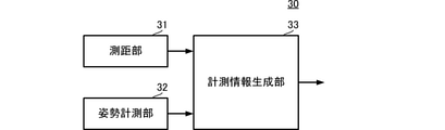
- FIG. 3 is a functional block diagram showing the configuration of the measurement unit.
- FIG. 4 is a functional block diagram showing the configuration of the calculation unit.
- FIG. 5 is a diagram showing an example of a method of designating provisional initial information.
- FIG. 6 is a diagram showing an example of a method for generating measurement information.
- FIG. 7 is a diagram showing an example of a method of setting initial information.
- 8 (A) and 8 (B) are flowcharts showing schematic processing of the ship navigation support method.
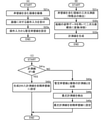
- FIG. 9 (A), 9 (B), and 9 (C) are flowcharts showing a specific processing flow of each process of the ship navigation support method shown in FIG. 8 (A).
- FIG. 10 is a flowchart showing an example of a method for detecting maximum likelihood measurement information.
- 11 (A), 11 (B), and 11 (C) show that the processing of FIGS. 9 (A), 9 (B), and 9 (C) is applied to a more specific target (quay). The case where it is set is shown.
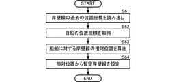
- FIG. 12 is a flowchart showing a process of setting provisional initial information from the past position coordinates of the feature information of the target object.
- FIG. 13 is a functional block diagram showing a configuration of a calculation unit when the feature information update process is included.
- FIG. 1 is a functional block diagram showing a configuration of a ship navigation support device according to an embodiment of the present invention.
- FIG. 2 is a functional block diagram showing the configuration of the provisional initial information setting unit.
- FIG. 3 is a functional block diagram showing the configuration of the measurement unit.
- FIG. 4 is a functional block diagram showing the configuration of the calculation unit.
- the ship navigation support device 10 includes a provisional initial information setting unit 20, a measurement unit 30, and a calculation unit 40.
- the ship navigation support device 10 executes a ship navigation support program and a storage device that stores a program (ship navigation support program) that realizes a ship navigation support method, excluding the optical system part and the radio wave system part, for example. It can be realized by an arithmetic processing device such as a CPU. Further, the part of the storage device and the arithmetic processing unit can be realized by an IC or the like in which a navigation support program is incorporated.
- the provisional initial information setting unit 20 accepts the designation of provisional initial information for the characteristic information of the target at which the ship is moored or berthed (berthed).
- the provisional initial information setting unit 20 outputs the provisional initial information to the calculation unit 40.
- the target is a quay
- the feature information is a vector quantity of the quay line
- the provisional initial information is a provisional quay line (vector quantity).
- the measuring unit 30 measures the distance to the area including the target where the ship is moored or berthed (berthed).
- the measurement unit 30 obtains measurement information for the target object by using the distance measurement result.
- the measurement unit 30 outputs the measurement information to the calculation unit 40.
- the measurement information is a vector quantity of a line segment (straight line).
- the calculation unit 40 sets the initial information of the feature information of the target object by using the provisional initial information and the measurement information.
- the initial information of the feature information of the target is the initial quay line (vector quantity).
- the ship navigation support device 10 sets the initial information (for example, the initial quay line) of the target based on the distance measurement result. Therefore, the ship navigation support device 10 can suppress an error in the initial information of the target object and set it with high accuracy. As a result, the ship navigation support device 10 can suppress the initial error when tracking the target object after that.
- the provisional initial information setting unit 20 includes a camera 21, an operation input unit 22, and a provisional initial information setting unit 23.
- the camera 21 is connected to the operation input unit 22.
- the camera 21 captures an area including a target (for example, a quay).
- the camera 21 outputs the captured image to the operation input unit 22.
- the operation input unit 22 is realized by, for example, a touch panel or the like.
- the operation input unit 22 displays the input image.
- the operation input unit 22 receives an operation input from the user and detects an operation position (operation locus) on the image.
- the operation input unit 22 outputs the operation position (operation locus) to the provisional initial information setting unit 23.
- the provisional initial information setting unit 23 converts the operation position (operation trajectory) into the vector quantity of the three-dimensional coordinate system set in the image, and sets it as the provisional initial information.
- the provisional initial information setting unit 23 outputs the provisional initial information to the calculation unit 40.
- FIG. 5 is a diagram showing an example of a method of designating provisional initial information.
- an image including the target quay 90 is displayed on the display screen.
- the operation input unit 22 detects the operation locus (the locus corresponding to the provisional quay line 920 in FIG. 5). More specifically, the operation input unit 22 detects a pixel group (pixel coordinate group) operated by a finger in the image as a locus. The operation input unit 22 outputs this locus to the provisional initial information setting unit 23.
- the provisional initial information setting unit 23 sets this locus as the provisional quay line 920.
- the provisional quay line 920 is represented by, for example, a vector quantity set by an orientation and a distance with respect to the position of the ship.
- the provisional quay line 920 corresponds to the provisional initial information.
- the provisional initial information setting unit 23 outputs the provisional quay line 920 to the calculation unit 40.
- the measurement unit 30 includes a distance measurement unit 31, a posture measurement unit 32, and a measurement information generation unit 33.
- the ranging unit 31 is realized by, for example, LIDAR or the like.
- the ranging unit 31 may be a lidar.
- the ranging unit 31 performs three-dimensional ranging on the area including the target object, and detects a plurality of feature points.
- the ranging unit 31 outputs a plurality of feature points to the measurement information generation unit 33.
- the posture measuring unit 32 is realized by, for example, a posture sensor equipped on a ship.
- the attitude sensor may be one using GNSS signal positioning technology or one using an inertial sensor. Further, the attitude sensor may be a combination of a GNSS signal positioning technique and an inertial sensor. If the positioning technology of the GNSS signal is used, the position (position coordinates) of the ship can also be measured. In addition, if the GNSS signal positioning technology is used, the attitude can be measured with high accuracy in an open sky situation such as at sea.
- the posture measuring unit 32 measures the posture of the ship.
- the attitude measurement unit 32 outputs the attitude of the ship to the measurement information generation unit 33.
- the measurement information generation unit 33 converts (projects) a plurality of feature points obtained in three-dimensional coordinates into a two-dimensional coordinate system on a horizontal plane. At this time, the measurement information generation unit 33 uses the posture of the ship, for example, to raise a plurality of feature points of the three-dimensional coordinate system to the two-dimensional coordinate system on the horizontal plane even if the ship is swinging. Can be converted to precision.
- the measurement information generation unit 33 applies a predetermined conversion process to a plurality of feature points arranged at two-dimensional coordinates on the horizontal plane to generate measurement information.
- the measurement information generation unit 33 outputs the generated measurement information to the calculation unit 40.
- FIG. 6 is a diagram showing an example of a method for generating measurement information.
- FIG. 6 shows a bird's-eye view of the detection result of LIDAR.
- LIDAR is used for the ranging unit 31 .
- the ranging unit 31 performs three-dimensional ranging on the area including the quay line 910 (not shown). As a result, the ranging unit 31 detects a plurality of feature points 81, 82, 83, 84, 85, 86, and 87, as shown in FIG. The ranging unit 31 outputs these plurality of feature points 81, 82, 83, 84, 85, 86, and 87 to the measurement information generation unit 33.
- the measurement information generation unit 33 applies the Hough transform or the like to the plurality of feature points 81, 82, 83, 84, 85, 86, 87 to measure the measurement lines 931, 932, 933, 934, 935, 936. , 937 are generated. Measurement lines 931, 932, 933, 934, 935, 936, 937 correspond to the measurement information. More specifically, the measurement information generation unit 33 generates the measurement line 931 from the plurality of feature points 81 arranged in a straight line, and generates the measurement line 932 from the plurality of feature points 82 arranged in a straight line.
- the measurement information generation unit 33 generates the measurement line 933 from the plurality of feature points 83, generates the measurement line 934 from the plurality of feature points 84, generates the measurement line 935 from the plurality of feature points 85, and generates a plurality of measurement lines 935.
- the measurement line 936 is generated from the feature points 86 of the above, and the measurement line 937 is generated from the plurality of feature points 87.
- These measurement lines 931, 932, 933, 934, 935, 936, 937 are represented by vector quantities set by the direction and distance with respect to the position of the ship.
- the measurement information generation unit 33 outputs these measurement lines 931, 932, 933, 934, 935, 936, 937 to the calculation unit 40.
- the calculation unit 40 includes a difference calculation unit 41 and an initial information setting unit 42.
- Temporary initial information is input from the provisional initial information setting unit 23 to the difference calculation unit 41, and measurement information is input from the measurement information generation unit 33.
- the difference calculation unit 41 compares the provisional initial information with the measurement information and calculates the difference.
- the difference calculation unit 41 outputs the difference between the provisional initial information and the measurement information for each set to the initial information setting unit 42.
- the initial information setting unit 42 compares the difference between the provisional initial information and the measurement information for each set.
- the initial information setting unit 42 detects the measurement information constituting the set having the smallest difference as the maximum likelihood measurement information.
- the initial information setting unit 42 sets the maximum likelihood measurement information as the initial information of the feature information of the target object.
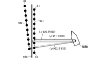
- FIG. 7 is a diagram showing an example of a method of setting initial information. Although FIG. 7 illustrates the concept of comparison between the measurement line 931 and the measurement line 932 and the provisional quay line 920, the same concept is applied to the other measurement lines.
- the provisional quay line 920 is obtained as a vector quantity ( ⁇ 920, ⁇ 920) of the distance and the direction with respect to the ship. Further, the measurement line 931 is obtained as a vector quantity of the distance and the direction with respect to the ship ( ⁇ 931, ⁇ 931), and the measurement line 932 is a vector quantity of the distance and the direction with respect to the ship ( ⁇ 932, ⁇ 932). Is obtained as.
- the difference calculation unit 41 calculates the difference between the provisional quay line 920 and the measurement line 931. That is, the difference calculation unit 41 calculates the distance difference ⁇ 1 and the orientation difference ⁇ 1 between the vector quantity ( ⁇ 920, ⁇ 920) and the vector quantity ( ⁇ 931, ⁇ 931). Similarly, the difference calculation unit 41 calculates the difference between the provisional quay line 920 and the measurement line 932. That is, the difference calculation unit 41 calculates the distance difference ⁇ 2 and the orientation difference ⁇ 2 between the vector quantity ( ⁇ 920, ⁇ 920) and the vector quantity ( ⁇ 932, ⁇ 932). The difference calculation unit 41 outputs the distance difference and the directional difference for each set of the provisional quay line and the measurement line to the initial information setting unit 42.
- the difference calculation unit 41 stores the bias error between the image coordinate system and the ranging coordinate system in advance, and after correcting the bias error, calculates the distance difference and the azimuth difference. As a result, the difference calculation unit 41 can calculate the distance difference and the directional difference with higher accuracy.
- the initial information setting unit 42 detects a set of the provisional quay line and the measurement line that minimizes the distance difference ⁇ , detects the measurement line constituting this set as the maximum likelihood measurement line, and sets it as the initial quay line. ..
- the initial information setting unit 42 detects a set of the provisional quay line and the measurement line that minimizes the azimuth difference ⁇ , detects the measurement line constituting this set as the maximum likelihood measurement line, and sets it as the initial quay line. Set.
- the initial information setting unit 42 comprehensively reflects the distance difference ⁇ and the azimuth difference ⁇ to set the initial quay line. For example, the initial information setting unit 42 sets the distance evaluation value according to the magnitude of the distance difference ⁇ , and sets the directional evaluation value according to the magnitude of the azimuth difference ⁇ . The initial information setting unit 42 determines the maximum likelihood measurement line using the distance evaluation value and the azimuth evaluation value. The initial information setting unit 42 sets the maximum likelihood measurement line to the initial quay line.
- the measurement line 931 is detected as the maximum likelihood measurement line for the provisional quay line 920 and is set as the initial quay line.
- the ship navigation support device 10 can set the initial information (initial quay line) of the target object (for example, the quay) with high accuracy.
- FIG. 8 (A) and 8 (B) are flowcharts showing the schematic processing of the ship navigation support method.
- FIG. 8B shows a case where the process of FIG. 8A is set for a more specific target (quay).
- the arithmetic processing unit (ship navigation support device) accepts the designation of provisional initial information of the feature information of the target object (S11).
- the arithmetic processing unit generates measurement information of the area including the target object (S12).
- the arithmetic processing unit sets the initial information of the feature information of the target object from the measurement information (S13).
- the arithmetic processing unit accepts the designation of the provisional quay line (S11e).
- the arithmetic processing unit generates a measurement line in a region including the quay line (S12e).
- the arithmetic processing unit sets the initial quay line from the measurement line (S13e).
- 9 (A), 9 (B), and 9 (C) are flowcharts showing a specific processing flow of each process of the ship navigation support method shown in FIG. 8 (A).
- the arithmetic processing unit captures an image including the target object (S21).
- the arithmetic processing unit accepts an operation input for an image (S22).
- the arithmetic processing unit sets provisional initial information from the contents of the operation input (S23).
- the arithmetic processing unit performs three-dimensional distance measurement of the area including the target object and detects a feature point (S31).
- the arithmetic processing device uses the attitude data of the ship to convert (project) the feature points measured in three dimensions into a two-dimensional coordinate system (S32).
- the arithmetic processing unit applies a predetermined conversion process to the plurality of feature points converted into the two-dimensional coordinate system, and generates measurement information (S33).
- the arithmetic processing unit uses this measurement information (generated measurement information) as a target object. It is set as the initial information of the feature information of (S42).
- the arithmetic processing unit compares the provisional initial information with the plurality of measurement information (S43).
- the arithmetic processing unit detects the maximum likelihood measurement information from the comparison result (S44). More specifically, for example, the process shown in FIG. 10 is executed.
- FIG. 10 is a flowchart showing an example of a method for detecting maximum likelihood measurement information.
- the arithmetic processing unit performs distance evaluation on a plurality of measurement information (S51).
- the distance evaluation is performed using the difference (distance difference) between the distance from the ship to the measurement information and the distance from the ship to the provisional initial information. For example, the smaller the distance difference, the higher the distance evaluation value is set. To.
- the arithmetic processing unit evaluates the orientation of a plurality of measurement information (S52).
- Directional evaluation is performed using the difference (direction difference) between the direction of the measurement information based on the position of the ship and the direction of the provisional initial information based on the ship. For example, the smaller the direction difference, the more the direction.
- the evaluation value is set high.
- the arithmetic processing unit determines the maximum likelihood measurement information from the distance evaluation value and the azimuth evaluation value (S53). For example, the arithmetic processing device sets a weighting coefficient for distance and a weighting coefficient for direction, multiplies the weighting coefficient for distance by the weight evaluation value, and multiplies the weighting coefficient for direction by the direction evaluation value. The arithmetic processing unit calculates a comprehensive evaluation value by adding these values, and sets the measurement information having the highest comprehensive evaluation value as the maximum likelihood measurement information.
- the method for setting the maximum likelihood measurement information is not limited to this, and at least one of the distance difference and the directional difference may be used. For example, the arithmetic processing unit can set the maximum likelihood measurement information in consideration of only the distance difference, or can set the maximum likelihood measurement information in consideration of only the directional difference.
- the arithmetic processing unit sets the maximum likelihood measurement information as the initial information of the feature information of the target object (S45).
- 11 (A), 11 (B), and 11 (C) show that the processing of FIGS. 9 (A), 9 (B), and 9 (C) is applied to a more specific target (quay). The case where it is set is shown.
- the arithmetic processing unit captures an image including the quay line (S21e).
- the arithmetic processing unit accepts an operation input for an image (S22e).
- the arithmetic processing unit sets a provisional quay line from the contents of the operation input (S23e).
- the arithmetic processing unit performs three-dimensional distance measurement of the region including the quay line and detects a feature point (S31e).
- the arithmetic processing device uses the attitude data of the ship to convert (project) the feature points measured in three dimensions into a two-dimensional coordinate system (S32e).
- the arithmetic processing unit applies a predetermined conversion process to a plurality of feature points converted into a two-dimensional coordinate system to generate a measurement line (S33e).
- the arithmetic processing unit in the initial quay line setting process, if the arithmetic processing unit has one measurement line (S41e: YES), the arithmetic processing unit initially uses this measurement line (generated measurement line). Set to the quay line (S42e).
- the arithmetic processing unit compares the provisional quay line with the plurality of measurement lines (S43e). The arithmetic processing unit detects the maximum likelihood measurement line from the comparison result (S44e). The arithmetic processing unit sets the maximum likelihood measurement line to the initial quay line (S45e).
- provisional initial information (provisional quay line)
- provisional initial information (provisional quay line) is set by the user's operation input.
- provisional initial information from past data on the feature information of the target.
- FIG. 12 is a flowchart showing a process of setting provisional initial information from the past position coordinates of the feature information of the target object.
- a mode in which the characteristic information of the target object is the quay line and the provisional initial information is the provisional quay line will be described.
- the arithmetic processing unit stores the past position coordinates of the quay line.
- the arithmetic processing unit reads out the past position coordinates of the quay line (S61).
- the arithmetic processing unit acquires the position coordinates of the ship (own ship) (S62).
- the acquisition of the position coordinates of the ship can be realized by using, for example, the above-mentioned GNSS signal positioning technique.
- the arithmetic processing unit calculates the relative position of the quay line with respect to the ship using these position coordinates (S63).
- the arithmetic processing unit sets a provisional quay line from a relative position (S64). For example, the arithmetic processing unit converts the relative position into a vector quantity set by the distance and direction with respect to the ship, and sets the provisional quay line.
- the mode in which the past position coordinates of the quay line are used is shown.
- a reference station on the quay line use a ship as a mobile station, detect a relative position using DGPS, RTK technology, or the like, and set a provisional quay line. It is also possible to receive the coordinates of the quay line from the outside and set the provisional quay line.
- FIG. 13 is a functional block diagram showing a configuration of a calculation unit when the feature information update process is included.
- the calculation unit 40A includes a difference calculation unit 41, an initial information setting unit 42, and a feature information update unit 43. That is, the calculation unit 40A differs from the calculation unit 40 in that the feature information update unit 43 is added.
- Other configurations of the calculation unit 40A are the same as those of the calculation unit 40, and the description of the same parts will be omitted.
- Initial information from the initial information setting unit 42 and measurement information from the measurement unit 30 are input to the feature information update unit 43.
- the feature information update unit 43 calculates the feature information using the initial information and the measurement information. Specifically, the feature information updating unit 43 calculates the difference between the initial information and the plurality of measurement information, respectively. The feature information updating unit 43 sets a weighting coefficient for each of the plurality of measurement information according to the difference. The feature information update unit 43 calculates the feature information by using the weighting coefficient and the plurality of measurement information. For example, the feature information update unit 43 calculates feature information by multiplying a plurality of measurement information by a weighting coefficient and adding the multiplication results.
- the feature information update unit 43 outputs this feature information and uses it for calculating the next feature information. That is, when the feature information has already been calculated, the feature information updating unit 43 calculates new feature information using the feature information and a plurality of newly input (acquired) measurement information. Specifically, the feature information updating unit 43 calculates the difference between the feature information and the plurality of measurement information, respectively. The feature information updating unit 43 sets a weighting coefficient for each of the plurality of measurement information according to the difference. The feature information update unit 43 calculates the feature information by using the weighting coefficient and the plurality of measurement information. For example, the feature information updating unit 43 calculates new feature information by multiplying a plurality of measurement information by a weighting coefficient and adding the multiplication results.
- the feature information updating unit 43 sequentially updates the feature information.
- the feature information (for example, the quay line) can be updated with high accuracy.
Landscapes
- Engineering & Computer Science (AREA)
- Radar, Positioning & Navigation (AREA)
- Remote Sensing (AREA)
- Automation & Control Theory (AREA)
- Physics & Mathematics (AREA)
- General Physics & Mathematics (AREA)
- Chemical & Material Sciences (AREA)
- Combustion & Propulsion (AREA)
- Mechanical Engineering (AREA)
- Ocean & Marine Engineering (AREA)
- Aviation & Aerospace Engineering (AREA)
- Navigation (AREA)
- Radar Systems Or Details Thereof (AREA)
Abstract
Description
図1に示すように、船舶航行支援装置10は、暫定初期情報設定部20、計測部30、および、演算部40を備える。船舶航行支援装置10は、例えば、光学系の部分、電波系の部分を除き、船舶航行支援方法を実現するプログラム(船舶航行支援プログラム)が記憶される記憶デバイスと、船舶航行支援プログラムを実行するCPU等の演算処理装置と、によって実現可能である。また、記憶デバイスと演算処理装置との部分は、航行支援プログラムが組み込まれたIC等によって実現することも可能である。
図2に示すように、暫定初期情報設定部20は、カメラ21、操作入力部22、および、暫定初期情報設定部23を備える。
図5は、暫定初期情報の指定方法の一例を示す図である。図5に示すように、表示画面には、目標物である岸壁90を含む画像が表示される。画面に表示された岸壁線910に沿うように、ユーザが指でタッチパネルを操作すると、操作入力部22は、操作の軌跡(図5における暫定岸壁線920に対応する軌跡)を検出する。より具体的には、操作入力部22は、軌跡として、画像における指で操作された画素群(画素の座標群)を検出する。操作入力部22は、この軌跡を、暫定初期情報設定部23に出力する。
図3に示すように、計測部30は、測距部31、姿勢計測部32、および、計測情報生成部33を備える。
図6は、計測情報の生成方法の一例を示す図である。図6は、LIDARの検出結果の鳥瞰図を示す。なお、ここでは、測距部31にLIDARを用いた場合を示す。
図4に示すように、演算部40は、差分算出部41および初期情報設定部42を備える。
図7は、初期情報の設定方法の一例を示す図である。なお、図7では、計測線931および計測線932と暫定岸壁線920との比較の概念について図示するが、他の計測線についても同様の概念が適用される。
上述の説明では、各処理をそれぞれに個別の機能部で実行する態様を示した。しかしながら、上述の処理は、船舶航行支援プログラムとして記憶され、演算処理装置で実行することによって、実現することが可能である。この場合、次の各図に示すフローにしたがって処理を実行すればよい。なお、以下の説明における具体的な処理の内容において、上述されている内容については、詳細な説明を省略する。
上述の説明では、暫定初期情報(暫定岸壁線)を、ユーザの操作入力によって設定した。しかしながら、目標物の特徴情報に対する過去のデータから、暫定初期情報を設定することも可能である。
20:暫定初期情報設定部
21:カメラ
22:操作入力部
23:暫定初期情報設定部
30:計測部
31:測距部
32:姿勢計測部
33:計測情報生成部
40、40A:演算部
41:差分算出部
42:初期情報設定部
43:特徴情報更新部
81、82、83、84、85、86、87:特徴点
90:岸壁
910:岸壁線
920:暫定岸壁線
931、932、933、934、935、936、937:計測線
Claims (23)
- 船舶の停泊目標である目標物の特徴情報に対する暫定初期情報の指定を受ける暫定初期情報設定部と、
前記目標物を含む領域に対する測距結果を用いて、前記目標物に対する計測情報を得る計測部と、
前記暫定初期情報と前記計測情報とを用いて、前記目標物の特徴情報の初期情報を設定する演算部と、
を備える、船舶航行支援装置。 - 請求項1に記載の船舶航行支援装置であって、
前記演算部は、
前記計測情報が複数得られたとき、それぞれの計測情報と前記暫定初期情報との差分を算出する差分算出部と、
前記差分が最小となる前記計測情報を前記特徴情報の初期情報に設定する、初期情報設定部と、
を備える、
船舶航行支援装置。 - 請求項2に記載の船舶航行支援装置であって、
前記初期情報設定部は、
前記船舶から前記計測情報までの距離と前記船舶から前記暫定初期情報までの距離との差が最小となる前記計測情報を、前記特徴情報の初期情報に設定する、
船舶航行支援装置。 - 請求項2または請求項3に記載の船舶航行支援装置であって、
前記初期情報設定部は、
前記船舶に対する前記計測情報の方位と、前記船舶に対する前記暫定初期情報の方位と差が最小となる前記計測情報を、前記特徴情報の初期情報に設定する、
船舶航行支援装置。 - 請求項1乃至請求項4のいずれかに記載の船舶航行支援装置であって、
前記計測部は、
前記目標物を含む領域の三次元座標系の測距を行って前記測距結果を出力する測距部と、
前記測距結果を二次元座標系に変換して前記計測情報を生成する計測情報生成部と、
を備える、
船舶航行支援装置。 - 請求項5に記載の船舶航行支援装置であって、
前記測距部は、光学測距計を備える、
船舶航行支援装置。 - 請求項5または請求項6に記載の船舶航行支援装置であって、
前記計測部は、前記船舶の姿勢を計測する姿勢計測部を備え、
前記計測情報生成部は、前記姿勢を用いて前記二次元座標系への変換を行う、
船舶航行支援装置。 - 請求項1乃至請求項7のいずれかに記載の船舶航行支援装置であって、
前記暫定初期情報設定部は、
前記目標物を含む画像を撮像する撮像部と、
前記画像を表示し、表示画像に対する操作入力を受け付ける操作入力部と、
前記操作入力から前記暫定初期情報を設定する暫定初期情報設定部と、
を備える、
船舶航行支援装置。 - 請求項1乃至請求項8のいずれかに記載の船舶航行支援装置であって、
前記目標物を含む画像を撮像する撮像部と、
前記画像から前記目標物に対する暫定目標物を検出する暫定目標物検出部と、
前記暫定目標物から前記暫定初期情報を設定する暫定初期情報設定部と、
を備える、
船舶航行支援装置。 - 請求項1乃至請求項9のいずれかに記載の船舶航行支援装置であって、
前記暫定初期情報設定部は、
前記目標物の過去の位置座標と前記船舶の位置座標とから、前記暫定初期情報を設定する、
船舶航行支援装置。 - 請求項1乃至請求項10のいずれかに記載の船舶航行支援装置であって、
前記暫定初期情報設定部は、
前記目標物の過去の位置座標と前記船舶の位置座標とを用いて、前記暫定初期情報を算出する、
船舶航行支援装置。 - 請求項1乃至請求項11のいずれかに記載の船舶航行支援装置であって、
前記目標物の特徴情報は、岸壁線である、
船舶航行支援装置。 - 請求項1乃至請求項12のいずれかに記載の船舶航行支援装置であって、
前記演算部は、
前記目標物に対する前記初期情報または前記目標物に対する更新前の特徴情報と前記計測情報とを用いて、前記目標物に対する特徴情報を更新する特徴情報更新部を、備える、
船舶航行支援装置。 - 船舶の停泊目標である目標物の特徴情報に対する暫定初期情報の指定を受け付け、
前記目標物を含む領域に対する測距結果を用いて、前記目標物に対する計測情報を得て、
前記暫定初期情報と前記計測情報とを用いて、前記目標物の特徴情報の初期情報を設定する、
船舶航行支援方法。 - 請求項14に記載の船舶航行支援方法であって、
前記計測情報が複数得られたとき、それぞれの計測情報と前記暫定初期情報との差分を算出し、
前記差分が最小となる前記計測情報を前記特徴情報の初期情報に設定する、
船舶航行支援方法。 - 請求項14または請求項15に記載の船舶航行支援方法であって、
前記目標物を含む領域の三次元座標系の測距を行って前記測距結果を出力し、
前記測距結果を二次元座標系に変換して前記計測情報を生成する、
船舶航行支援方法。 - 請求項16に記載の船舶航行支援方法であって、
前記船舶の姿勢を計測し、
前記姿勢を用いて前記二次元座標系への変換を行う、
船舶航行支援方法。 - 請求項14乃至請求項17のいずれかに記載の船舶航行支援方法であって、
前記目標物に対する前記初期情報または前記目標物に対する更新前の特徴情報と前記計測情報とを用いて、前記目標物に対する特徴情報を更新する、
船舶航行支援方法。 - 船舶の停泊目標である目標物の特徴情報に対する暫定初期情報の指定を受け付け、
前記目標物を含む領域に対する測距結果を用いて、前記目標物に対する計測情報を得て、
前記暫定初期情報と前記計測情報とを用いて、前記目標物の特徴情報の初期情報を設定する、
処理を演算処理装置に実行させる船舶航行支援プログラム。 - 請求項19に記載の船舶航行支援プログラムであって、
前記計測情報が複数得られたとき、それぞれの計測情報と前記暫定初期情報との差分を算出し、
前記差分が最小となる前記計測情報を前記特徴情報の初期情報に設定する、
処理を演算処理装置に実行させる船舶航行支援プログラム。 - 請求項19または請求項20に記載の船舶航行支援プログラムであって、
前記目標物を含む領域の三次元座標系の測距を行って前記測距結果を出力し、
前記測距結果を二次元座標系に変換して前記計測情報を生成する、
処理を演算処理装置に実行させる船舶航行支援プログラム。 - 請求項21に記載の船舶航行支援プログラムであって、
前記船舶の姿勢を計測し、
前記姿勢を用いて前記二次元座標系への変換を行う、
処理を演算処理装置に実行させる船舶航行支援プログラム。 - 請求項19乃至請求項22のいずれかに記載の船舶航行支援プログラムであって、
前記目標物に対する前記初期情報または前記目標物に対する更新前の特徴情報と前記計測情報とを用いて、前記目標物に対する特徴情報を更新する、
処理を演算処理装置に実行させる船舶航行支援プログラム。
Priority Applications (5)
| Application Number | Priority Date | Filing Date | Title |
|---|---|---|---|
| JP2022545532A JP7744351B2 (ja) | 2020-08-24 | 2021-07-16 | 船舶航行支援装置、船舶航行支援方法、および、船舶航行支援プログラム |
| EP21861038.4A EP4201800B1 (en) | 2020-08-24 | 2021-07-16 | Watercraft navigation assistance device, watercraft navigation assistance method, and watercraft navigation assistance program |
| CN202180034337.2A CN115551778B (zh) | 2020-08-24 | 2021-07-16 | 船舶航行支援装置、船舶航行支援方法以及船舶航行支援程序 |
| KR1020237008048A KR20230053621A (ko) | 2020-08-24 | 2021-07-16 | 선박 항행 지원 장치, 선박 항행 지원 방법, 및, 선박 항행 지원 프로그램 |
| US18/174,408 US12411011B2 (en) | 2020-08-24 | 2023-02-24 | Ship navigation assistance device, ship navigation assistance method, and ship navigation assistance program |
Applications Claiming Priority (2)
| Application Number | Priority Date | Filing Date | Title |
|---|---|---|---|
| JP2020140551 | 2020-08-24 | ||
| JP2020-140551 | 2020-08-24 |
Related Child Applications (1)
| Application Number | Title | Priority Date | Filing Date |
|---|---|---|---|
| US18/174,408 Continuation-In-Part US12411011B2 (en) | 2020-08-24 | 2023-02-24 | Ship navigation assistance device, ship navigation assistance method, and ship navigation assistance program |
Publications (1)
| Publication Number | Publication Date |
|---|---|
| WO2022044609A1 true WO2022044609A1 (ja) | 2022-03-03 |
Family
ID=80355027
Family Applications (1)
| Application Number | Title | Priority Date | Filing Date |
|---|---|---|---|
| PCT/JP2021/026772 Ceased WO2022044609A1 (ja) | 2020-08-24 | 2021-07-16 | 船舶航行支援装置、船舶航行支援方法、および、船舶航行支援プログラム |
Country Status (6)
| Country | Link |
|---|---|
| US (1) | US12411011B2 (ja) |
| EP (1) | EP4201800B1 (ja) |
| JP (1) | JP7744351B2 (ja) |
| KR (1) | KR20230053621A (ja) |
| CN (1) | CN115551778B (ja) |
| WO (1) | WO2022044609A1 (ja) |
Cited By (3)
| Publication number | Priority date | Publication date | Assignee | Title |
|---|---|---|---|---|
| CN115344033A (zh) * | 2022-03-10 | 2022-11-15 | 西北工业大学 | 一种基于单目相机/imu/dvl紧耦合的无人船导航与定位方法 |
| EP4494996A4 (en) * | 2022-03-15 | 2025-11-19 | Pioneer Corp | INFORMATION PROCESSING DEVICE, CONTROL METHOD, PROGRAM, AND RECORDING MEDIUM |
| EP4495723A4 (en) * | 2022-03-15 | 2025-12-31 | Pioneer Corp | INFORMATION PROCESSING DEVICE, CONTROL METHOD, PROGRAM AND RECORDING MEDIUM |
Citations (4)
| Publication number | Priority date | Publication date | Assignee | Title |
|---|---|---|---|---|
| JP2007041499A (ja) * | 2005-07-01 | 2007-02-15 | Advanced Telecommunication Research Institute International | 雑音抑圧装置、コンピュータプログラム、及び音声認識システム |
| JP2007106397A (ja) * | 2005-09-15 | 2007-04-26 | Yamaha Motor Co Ltd | 着岸支援装置およびそれを備えた船舶 |
| JP2012161444A (ja) * | 2011-02-07 | 2012-08-30 | Hitachi Medical Corp | X線ct装置 |
| JP2019079352A (ja) * | 2017-10-25 | 2019-05-23 | 新日鐵住金株式会社 | 情報処理装置、情報処理方法及びプログラム |
Family Cites Families (14)
| Publication number | Priority date | Publication date | Assignee | Title |
|---|---|---|---|---|
| JPS50244B1 (ja) | 1970-08-04 | 1975-01-07 | ||
| JP3777411B2 (ja) * | 2003-08-08 | 2006-05-24 | 今津隼馬 | 船舶航行支援装置 |
| JP4716214B2 (ja) * | 2004-11-12 | 2011-07-06 | 株式会社三井造船昭島研究所 | 船舶の入出港離着桟支援方法およびシステム |
| JP2011169801A (ja) * | 2010-02-19 | 2011-09-01 | Royal Kogyo Kk | 航行情報表示装置 |
| JP6343469B2 (ja) * | 2014-03-26 | 2018-06-13 | 株式会社エヌ・ティ・ティ・データ | 航行支援装置、航行支援方法、航行支援プログラム |
| US11505292B2 (en) * | 2014-12-31 | 2022-11-22 | FLIR Belgium BVBA | Perimeter ranging sensor systems and methods |
| CN105842724B (zh) * | 2015-01-15 | 2018-07-17 | 江苏南大五维电子科技有限公司 | 一种船舶辅助泊岸方法和系统 |
| CN104615880B (zh) * | 2015-01-31 | 2017-08-01 | 电子科技大学中山学院 | 一种三维激光雷达点云匹配的快速icp方法 |
| CN106199625A (zh) * | 2016-07-05 | 2016-12-07 | 上海交通大学 | 一种基于激光雷达的船舶靠泊检测系统和方法 |
| WO2018100746A1 (ja) * | 2016-12-02 | 2018-06-07 | ヤマハ発動機株式会社 | 小型船舶及びその制御方法 |
| JPWO2019004362A1 (ja) * | 2017-06-30 | 2020-04-30 | 川崎重工業株式会社 | 船舶の運航支援装置及び運航支援プログラム |
| JP7083081B2 (ja) * | 2018-10-10 | 2022-06-10 | ヤンマーパワーテクノロジー株式会社 | 自動着岸装置 |
| CN109740828B (zh) * | 2019-02-28 | 2021-07-30 | 广州中国科学院沈阳自动化研究所分所 | 船舶航行路径规划方法、系统、介质和设备 |
| WO2022044608A1 (ja) * | 2020-08-24 | 2022-03-03 | 古野電気株式会社 | 船舶航行支援装置、船舶航行支援方法、および、船舶航行支援プログラム |
-
2021
- 2021-07-16 EP EP21861038.4A patent/EP4201800B1/en active Active
- 2021-07-16 CN CN202180034337.2A patent/CN115551778B/zh active Active
- 2021-07-16 KR KR1020237008048A patent/KR20230053621A/ko active Pending
- 2021-07-16 JP JP2022545532A patent/JP7744351B2/ja active Active
- 2021-07-16 WO PCT/JP2021/026772 patent/WO2022044609A1/ja not_active Ceased
-
2023
- 2023-02-24 US US18/174,408 patent/US12411011B2/en active Active
Patent Citations (5)
| Publication number | Priority date | Publication date | Assignee | Title |
|---|---|---|---|---|
| JP2007041499A (ja) * | 2005-07-01 | 2007-02-15 | Advanced Telecommunication Research Institute International | 雑音抑圧装置、コンピュータプログラム、及び音声認識システム |
| JP2007106397A (ja) * | 2005-09-15 | 2007-04-26 | Yamaha Motor Co Ltd | 着岸支援装置およびそれを備えた船舶 |
| JP5000244B2 (ja) | 2005-09-15 | 2012-08-15 | ヤマハ発動機株式会社 | 着岸支援装置およびそれを備えた船舶 |
| JP2012161444A (ja) * | 2011-02-07 | 2012-08-30 | Hitachi Medical Corp | X線ct装置 |
| JP2019079352A (ja) * | 2017-10-25 | 2019-05-23 | 新日鐵住金株式会社 | 情報処理装置、情報処理方法及びプログラム |
Non-Patent Citations (1)
| Title |
|---|
| See also references of EP4201800A4 |
Cited By (3)
| Publication number | Priority date | Publication date | Assignee | Title |
|---|---|---|---|---|
| CN115344033A (zh) * | 2022-03-10 | 2022-11-15 | 西北工业大学 | 一种基于单目相机/imu/dvl紧耦合的无人船导航与定位方法 |
| EP4494996A4 (en) * | 2022-03-15 | 2025-11-19 | Pioneer Corp | INFORMATION PROCESSING DEVICE, CONTROL METHOD, PROGRAM, AND RECORDING MEDIUM |
| EP4495723A4 (en) * | 2022-03-15 | 2025-12-31 | Pioneer Corp | INFORMATION PROCESSING DEVICE, CONTROL METHOD, PROGRAM AND RECORDING MEDIUM |
Also Published As
| Publication number | Publication date |
|---|---|
| KR20230053621A (ko) | 2023-04-21 |
| CN115551778B (zh) | 2026-01-27 |
| JP7744351B2 (ja) | 2025-09-25 |
| EP4201800A4 (en) | 2024-10-02 |
| US20230228572A1 (en) | 2023-07-20 |
| CN115551778A (zh) | 2022-12-30 |
| EP4201800A1 (en) | 2023-06-28 |
| JPWO2022044609A1 (ja) | 2022-03-03 |
| US12411011B2 (en) | 2025-09-09 |
| EP4201800B1 (en) | 2026-01-28 |
Similar Documents
| Publication | Publication Date | Title |
|---|---|---|
| JP7744351B2 (ja) | 船舶航行支援装置、船舶航行支援方法、および、船舶航行支援プログラム | |
| CN115551779B (zh) | 船舶航行支援装置、船舶航行支援方法以及船舶航行支援程序 | |
| US11964737B2 (en) | Ship information displaying system, ship information displaying method and image generating device | |
| US20220317314A1 (en) | Satellite attitude estimation system and satellite attitude estimation method | |
| EP4349707A1 (en) | Vessel navigation assistance device, vessel navigation assistance method, and vessel navigation assistance program | |
| US6819984B1 (en) | LOST 2—a positioning system for under water vessels | |
| CN111819418A (zh) | 导航装置、vslam校正方法、空间信息估计方法、vslam校正程序及空间信息估计程序 | |
| US20240320846A1 (en) | Target monitoring device, target monitoring method, and recording medium | |
| JP2017211307A (ja) | 測定装置、測定方法およびプログラム | |
| WO2021112177A1 (ja) | 情報処理装置、制御方法、プログラム及び記憶媒体 | |
| JP2018036151A (ja) | ランドマークを用いた測位方法 | |
| RU2107897C1 (ru) | Способ инерциальной навигации | |
| CN109459046A (zh) | 悬浮式水下自主航行器的定位和导航方法 | |
| JP6321914B2 (ja) | 移動体情報算出装置、移動体情報取得装置、移動体、移動体情報算出方法、移動体情報取得方法、移動体情報算出プログラム、および移動体情報取得プログラム | |
| Noguchi et al. | Wide area seafloor imaging by a low-cost AUV | |
| CN118279388A (zh) | 一种基于增强现实的船舶靠离泊辅助系统 | |
| JP3192448B2 (ja) | 潮流計 | |
| JP3439068B2 (ja) | センサ姿勢及び位置のバイアス誤差推定装置 | |
| Van et al. | Improved Hydrographic Surveying Accuracy with the Use of GPS/IMU and Single Beam Echo Sounder | |
| CN113495255A (zh) | 一种确定车辆上搭载的激光雷达姿态的方法和装置 | |
| US11255675B2 (en) | Course estimating device, method of estimating course, and course estimating program | |
| EP4400405A1 (en) | Information processing device, determining method, program, and storage medium | |
| CN121632160A (zh) | 基于马氏距离约束的单信标距离圆定位辅助ins导航方法 | |
| CN121120915A (zh) | 一种水下物体建模方法、水下机器人及可读存储介质 | |
| WO2025126808A1 (ja) | 航行支援装置、航行支援データ生成方法、航行支援データ生成プログラム |
Legal Events
| Date | Code | Title | Description |
|---|---|---|---|
| 121 | Ep: the epo has been informed by wipo that ep was designated in this application |
Ref document number: 21861038 Country of ref document: EP Kind code of ref document: A1 |
|
| ENP | Entry into the national phase |
Ref document number: 2022545532 Country of ref document: JP Kind code of ref document: A |
|
| ENP | Entry into the national phase |
Ref document number: 20237008048 Country of ref document: KR Kind code of ref document: A |
|
| NENP | Non-entry into the national phase |
Ref country code: DE |
|
| ENP | Entry into the national phase |
Ref document number: 2021861038 Country of ref document: EP Effective date: 20230324 |
|
| WWG | Wipo information: grant in national office |
Ref document number: 2021861038 Country of ref document: EP |