WO2022044853A1 - センシングシステム及び車両 - Google Patents
センシングシステム及び車両 Download PDFInfo
- Publication number
- WO2022044853A1 WO2022044853A1 PCT/JP2021/029818 JP2021029818W WO2022044853A1 WO 2022044853 A1 WO2022044853 A1 WO 2022044853A1 JP 2021029818 W JP2021029818 W JP 2021029818W WO 2022044853 A1 WO2022044853 A1 WO 2022044853A1
- Authority
- WO
- WIPO (PCT)
- Prior art keywords
- vehicle
- control unit
- sensing system
- foreign matter
- translucent cover
- Prior art date
- Legal status (The legal status is an assumption and is not a legal conclusion. Google has not performed a legal analysis and makes no representation as to the accuracy of the status listed.)
- Ceased
Links
Images

Classifications
-
- B—PERFORMING OPERATIONS; TRANSPORTING
- B60—VEHICLES IN GENERAL
- B60Q—ARRANGEMENT OF SIGNALLING OR LIGHTING DEVICES, THE MOUNTING OR SUPPORTING THEREOF OR CIRCUITS THEREFOR, FOR VEHICLES IN GENERAL
- B60Q1/00—Arrangement of optical signalling or lighting devices, the mounting or supporting thereof or circuits therefor
- B60Q1/0017—Devices integrating an element dedicated to another function
- B60Q1/0023—Devices integrating an element dedicated to another function the element being a sensor, e.g. distance sensor, camera
-
- B—PERFORMING OPERATIONS; TRANSPORTING
- B60—VEHICLES IN GENERAL
- B60Q—ARRANGEMENT OF SIGNALLING OR LIGHTING DEVICES, THE MOUNTING OR SUPPORTING THEREOF OR CIRCUITS THEREFOR, FOR VEHICLES IN GENERAL
- B60Q1/00—Arrangement of optical signalling or lighting devices, the mounting or supporting thereof or circuits therefor
- B60Q1/02—Arrangement of optical signalling or lighting devices, the mounting or supporting thereof or circuits therefor the devices being primarily intended to illuminate the way ahead or to illuminate other areas of way or environments
- B60Q1/04—Arrangement of optical signalling or lighting devices, the mounting or supporting thereof or circuits therefor the devices being primarily intended to illuminate the way ahead or to illuminate other areas of way or environments the devices being headlights
- B60Q1/14—Arrangement of optical signalling or lighting devices, the mounting or supporting thereof or circuits therefor the devices being primarily intended to illuminate the way ahead or to illuminate other areas of way or environments the devices being headlights having dimming means
- B60Q1/1415—Dimming circuits
- B60Q1/1423—Automatic dimming circuits, i.e. switching between high beam and low beam due to change of ambient light or light level in road traffic
- B60Q1/143—Automatic dimming circuits, i.e. switching between high beam and low beam due to change of ambient light or light level in road traffic combined with another condition, e.g. using vehicle recognition from camera images or activation of wipers
-
- G—PHYSICS
- G01—MEASURING; TESTING
- G01S—RADIO DIRECTION-FINDING; RADIO NAVIGATION; DETERMINING DISTANCE OR VELOCITY BY USE OF RADIO WAVES; LOCATING OR PRESENCE-DETECTING BY USE OF THE REFLECTION OR RERADIATION OF RADIO WAVES; ANALOGOUS ARRANGEMENTS USING OTHER WAVES
- G01S17/00—Systems using the reflection or reradiation of electromagnetic waves other than radio waves, e.g. lidar systems
- G01S17/86—Combinations of lidar systems with systems other than lidar, radar or sonar, e.g. with direction finders
-
- G—PHYSICS
- G01—MEASURING; TESTING
- G01S—RADIO DIRECTION-FINDING; RADIO NAVIGATION; DETERMINING DISTANCE OR VELOCITY BY USE OF RADIO WAVES; LOCATING OR PRESENCE-DETECTING BY USE OF THE REFLECTION OR RERADIATION OF RADIO WAVES; ANALOGOUS ARRANGEMENTS USING OTHER WAVES
- G01S17/00—Systems using the reflection or reradiation of electromagnetic waves other than radio waves, e.g. lidar systems
- G01S17/87—Combinations of systems using electromagnetic waves other than radio waves
-
- G—PHYSICS
- G01—MEASURING; TESTING
- G01S—RADIO DIRECTION-FINDING; RADIO NAVIGATION; DETERMINING DISTANCE OR VELOCITY BY USE OF RADIO WAVES; LOCATING OR PRESENCE-DETECTING BY USE OF THE REFLECTION OR RERADIATION OF RADIO WAVES; ANALOGOUS ARRANGEMENTS USING OTHER WAVES
- G01S17/00—Systems using the reflection or reradiation of electromagnetic waves other than radio waves, e.g. lidar systems
- G01S17/88—Lidar systems specially adapted for specific applications
- G01S17/93—Lidar systems specially adapted for specific applications for anti-collision purposes
- G01S17/931—Lidar systems specially adapted for specific applications for anti-collision purposes of land vehicles
-
- G—PHYSICS
- G01—MEASURING; TESTING
- G01S—RADIO DIRECTION-FINDING; RADIO NAVIGATION; DETERMINING DISTANCE OR VELOCITY BY USE OF RADIO WAVES; LOCATING OR PRESENCE-DETECTING BY USE OF THE REFLECTION OR RERADIATION OF RADIO WAVES; ANALOGOUS ARRANGEMENTS USING OTHER WAVES
- G01S7/00—Details of systems according to groups G01S13/00, G01S15/00, G01S17/00
- G01S7/48—Details of systems according to groups G01S13/00, G01S15/00, G01S17/00 of systems according to group G01S17/00
- G01S7/497—Means for monitoring or calibrating
-
- G—PHYSICS
- G06—COMPUTING OR CALCULATING; COUNTING
- G06V—IMAGE OR VIDEO RECOGNITION OR UNDERSTANDING
- G06V10/00—Arrangements for image or video recognition or understanding
- G06V10/40—Extraction of image or video features
- G06V10/60—Extraction of image or video features relating to illumination properties, e.g. using a reflectance or lighting model
-
- G—PHYSICS
- G06—COMPUTING OR CALCULATING; COUNTING
- G06V—IMAGE OR VIDEO RECOGNITION OR UNDERSTANDING
- G06V20/00—Scenes; Scene-specific elements
- G06V20/50—Context or environment of the image
- G06V20/56—Context or environment of the image exterior to a vehicle by using sensors mounted on the vehicle
-
- G—PHYSICS
- G06—COMPUTING OR CALCULATING; COUNTING
- G06V—IMAGE OR VIDEO RECOGNITION OR UNDERSTANDING
- G06V20/00—Scenes; Scene-specific elements
- G06V20/50—Context or environment of the image
- G06V20/56—Context or environment of the image exterior to a vehicle by using sensors mounted on the vehicle
- G06V20/58—Recognition of moving objects or obstacles, e.g. vehicles or pedestrians; Recognition of traffic objects, e.g. traffic signs, traffic lights or roads
-
- B—PERFORMING OPERATIONS; TRANSPORTING
- B60—VEHICLES IN GENERAL
- B60S—SERVICING, CLEANING, REPAIRING, SUPPORTING, LIFTING, OR MANOEUVRING OF VEHICLES, NOT OTHERWISE PROVIDED FOR
- B60S1/00—Cleaning of vehicles
- B60S1/02—Cleaning windscreens, windows or optical devices
- B60S1/04—Wipers or the like, e.g. scrapers
- B60S1/06—Wipers or the like, e.g. scrapers characterised by the drive
- B60S1/08—Wipers or the like, e.g. scrapers characterised by the drive electrically driven
- B60S1/0818—Wipers or the like, e.g. scrapers characterised by the drive electrically driven including control systems responsive to external conditions, e.g. by detection of moisture, dirt or the like
- B60S1/0822—Wipers or the like, e.g. scrapers characterised by the drive electrically driven including control systems responsive to external conditions, e.g. by detection of moisture, dirt or the like characterized by the arrangement or type of detection means
- B60S1/0833—Optical rain sensor
- B60S1/0844—Optical rain sensor including a camera
-
- B—PERFORMING OPERATIONS; TRANSPORTING
- B60—VEHICLES IN GENERAL
- B60S—SERVICING, CLEANING, REPAIRING, SUPPORTING, LIFTING, OR MANOEUVRING OF VEHICLES, NOT OTHERWISE PROVIDED FOR
- B60S1/00—Cleaning of vehicles
- B60S1/02—Cleaning windscreens, windows or optical devices
- B60S1/56—Cleaning windscreens, windows or optical devices specially adapted for cleaning other parts or devices than front windows or windscreens
-
- B—PERFORMING OPERATIONS; TRANSPORTING
- B60—VEHICLES IN GENERAL
- B60S—SERVICING, CLEANING, REPAIRING, SUPPORTING, LIFTING, OR MANOEUVRING OF VEHICLES, NOT OTHERWISE PROVIDED FOR
- B60S1/00—Cleaning of vehicles
- B60S1/02—Cleaning windscreens, windows or optical devices
- B60S1/56—Cleaning windscreens, windows or optical devices specially adapted for cleaning other parts or devices than front windows or windscreens
- B60S1/60—Cleaning windscreens, windows or optical devices specially adapted for cleaning other parts or devices than front windows or windscreens for signalling devices, e.g. reflectors
- B60S1/603—Cleaning windscreens, windows or optical devices specially adapted for cleaning other parts or devices than front windows or windscreens for signalling devices, e.g. reflectors the operation of at least a part of the cleaning means being controlled by electric means
-
- G—PHYSICS
- G01—MEASURING; TESTING
- G01S—RADIO DIRECTION-FINDING; RADIO NAVIGATION; DETERMINING DISTANCE OR VELOCITY BY USE OF RADIO WAVES; LOCATING OR PRESENCE-DETECTING BY USE OF THE REFLECTION OR RERADIATION OF RADIO WAVES; ANALOGOUS ARRANGEMENTS USING OTHER WAVES
- G01S7/00—Details of systems according to groups G01S13/00, G01S15/00, G01S17/00
- G01S7/48—Details of systems according to groups G01S13/00, G01S15/00, G01S17/00 of systems according to group G01S17/00
- G01S7/497—Means for monitoring or calibrating
- G01S2007/4975—Means for monitoring or calibrating of sensor obstruction by, e.g. dirt- or ice-coating, e.g. by reflection measurement on front-screen
Definitions
- This disclosure relates to a sensing system and a vehicle equipped with the sensing system.
- the ADB (Adaptive Driving Beam) light distribution pattern including the irradiated area and the non-irradiated area is provided in front of the vehicle.
- a lighting unit that emits light toward an area is disclosed.
- the lighting unit emits an ADB light distribution pattern toward the front region so that the vehicle in front is included in the non-irradiated region.
- a sensor such as a camera is arranged in the lighting room of the vehicle lighting equipment, and an object such as a vehicle in front is detected based on the image data acquired by the camera.
- the lighting control unit that controls the drive of the lighting unit emits the ADB light distribution pattern toward the front of the vehicle so that the detected object is included in the non-irradiated region.
- the foreign matter adhering to the translucent cover causes the vehicle to move forward accurately based on the image data from the camera. It is assumed that information related to the vehicle (position information of the vehicle in front, etc.) cannot be acquired. In such a case, the vehicle in front may overlap a part of the irradiation region of the light distribution pattern for ADB, and glare light may be given to the occupants of the vehicle in front. In this way, even if foreign matter adheres to the translucent cover, it is possible to prevent a decrease in recognition accuracy for an object (for example, another vehicle) existing outside the vehicle. There is room to consider the sensing system.
- the object of the present disclosure is to provide a sensing system capable of preventing a decrease in cognitive accuracy for an object existing outside the sensing system.
- the sensing system is A control unit configured to acquire information about an object existing outside the sensing system, and a control unit.
- a first sensor located in a space formed by a translucent cover and a housing and configured to acquire first data indicating the external surrounding environment.
- a cover cleaner configured to remove foreign matter adhering to the translucent cover, To prepare for.
- the control unit It is determined whether or not foreign matter is attached to the translucent cover, and the cover cleaner is driven according to the determination that foreign matter is attached to the translucent cover.
- information about the object is acquired based on the first data.
- the second data indicating the external surrounding environment is acquired from the second sensor arranged outside the space, and then based on the acquired second data. It is configured to acquire information about the object.
- the translucent cover when no foreign matter adheres to the translucent cover, it is based on the first data acquired by the first sensor arranged in the space formed by the translucent cover and the housing. , Information about an object that exists outside the sensing system is acquired. On the other hand, when a foreign substance adheres to the translucent cover, information about the object is acquired based on the second data acquired by the second sensor arranged outside the space. As described above, it is possible to provide a sensing system capable of preventing a decrease in cognitive accuracy for an object even when a foreign substance is attached to the translucent cover.
- a sensing system capable of preventing a decrease in cognitive accuracy for an object existing outside the sensing system.
- the front view of the vehicle is shown. It is a block diagram of a vehicle system. It is a block diagram of the left sensing system. It is a figure which shows an example of the light distribution pattern for ADB and the light distribution pattern for low beam formed on the virtual vertical screen schematically. It is a flowchart for demonstrating the foreign matter adhesion determination process. It is a top view of a vehicle equipped with a rear camera module.
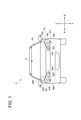
- FIG. 1 shows a front view of the vehicle 1.
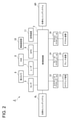
- FIG. 2 is a block diagram of the vehicle system 2 mounted on the vehicle 1.
- the vehicle 1 includes the vehicle system 2 shown in FIG. As shown in FIG. 2, the vehicle system 2 includes a vehicle control unit 3, a left side sensing system 4L, and a right side sensing system 4R. The left side sensing system 4L and the right side sensing system 4R are examples of vehicle sensing systems. Further, the vehicle system 2 includes a sensor 5, a second camera 6, a radar 7, an HMI (Human Machine Interface) 8, a GPS (Global Positioning System) 9, a wireless communication unit 10, and a storage device 11. Be prepared. Further, the vehicle system 2 includes a steering actuator 12, a steering device 13, a brake actuator 14, a brake device 15, an accelerator actuator 16, and an accelerator device 17.
- a steering actuator 12 a steering device 13, a brake actuator 14, a brake device 15, an accelerator actuator 16, and an accelerator device 17.
- the vehicle control unit 3 is configured to control the running of the vehicle 1.
- the vehicle control unit 3 is composed of, for example, at least one electronic control unit (ECU: Electronic Control Unit).
- the electronic control unit includes a computer system including one or more processors and one or more memories (for example, SoC (System on a Chip) or the like), and an electronic circuit composed of active elements such as transistors and passive elements.
- the processor includes, for example, at least one of a CPU (Central Processing Unit), an MPU (Micro Processing Unit), and a GPU (Graphics Processing Unit).
- the memory includes a ROM (Read Only Memory) and a RAM (Random Access Memory).
- the vehicle control program may be stored in the ROM.
- the vehicle control program may include an artificial intelligence (AI) program for autonomous driving.
- AI artificial intelligence
- An AI program is a program (trained model) constructed by supervised or unsupervised machine learning (particularly deep learning) using a multi-layer neural network.
- the RAM may temporarily store a vehicle control program, vehicle control data, and / or peripheral environment information indicating the surrounding environment of the vehicle.
- the processor may be configured to develop a program designated from various vehicle control programs stored in the ROM on the RAM and execute various processes in cooperation with the RAM.
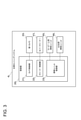
- the left side sensing system 4L includes a low beam lighting unit 45L, an ADB (Adaptive Driving Beam) lighting unit 46L, a first camera 43L, a cover cleaner 47L, and a control unit 20L.
- the low beam lighting unit 45L, the ADB lighting unit 46L, and the first camera 43L are arranged in the space SL located on the left front side of the vehicle 1 (see FIG. 1).
- the space SL is a lamp chamber formed by a lamp housing 42L (an example of a housing) and a translucent lamp cover 40L (an example of a translucent cover).
- the low beam lighting unit 45L includes, for example, a light emitting element (for example, an LED) that emits light, a reflector that reflects the light emitted from the light emitting element forward, and a part of the light reflected by the reflector. Has a shade that blocks light.
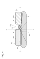
- the low beam lighting unit 45L is configured to irradiate the front region of the vehicle 1 with the low beam light distribution pattern PL (see FIG. 4).
- the low beam light distribution pattern PL is a light distribution pattern formed on a virtual vertical screen virtually arranged 25 m in front of the vehicle 1.
- the low beam light distribution pattern PL has an oncoming lane side cut-off line CL1, an own lane side cut-off line CL2, and an oblique cut-off line CL3 connected to these cut-off line CL1 and CL2.
- the ADB lighting unit 46L is configured to irradiate the front region of the vehicle 1 with the ADB light distribution pattern PH.
- the light distribution pattern PH for ADB is a light distribution pattern formed on a virtual vertical screen.
- the light distribution pattern PH for ADB has an irradiation region PH1 that is irradiated with light and a non-irradiation region PH2 that is not irradiated with light.
- the ADB lighting unit 46L uses the ADB light distribution pattern PH so that the object is included in the non-irradiation region PH2. Formed in front of 1.
- the front vehicle 1A is located between the left end portion El and the right end portion Er of the non-irradiation region PH2. In this way, it is preferably prevented that glare light is applied to an object such as the vehicle in front 1A.
- the ADB lighting unit 46L forms an ADB light distribution pattern (that is, a high beam light distribution pattern) including only the irradiation region PH1 in front of the vehicle 1. do.
- the ADB lighting unit 46L irradiates the ADB light distribution pattern or the high beam light distribution pattern having the non-irradiation region PH2 toward the front depending on the presence or absence of the object.
- the ADB lighting unit 46L is emitted from, for example, a plurality of light emitting elements (for example, LEDs) arranged in a matrix (n rows ⁇ m columns, n and m are integers of 1 or more) and a plurality of light emitting elements. It may be provided with a projection lens that allows light to pass through. In this case, by individually controlling the turning on and off of each light emitting element, the ADB lighting unit 46L forms an ADB light distribution pattern PH having an irradiation region PH1 and a non-irradiation region PH2 in front of the vehicle 1. be able to.
- the ADB lighting unit 46L may include, for example, a light emitting element that emits light, a reflector, a MEMS (Micro Electro Mechanical Systems) mirror, and a projection lens.
- the reflector is configured to reflect the light emitted from the light emitting element toward the MEMS mirror.
- the MEMS mirror is configured to reflect the light reflected by the reflector toward the projection lens.
- the MEMS mirror includes a plurality of micromirror elements arranged in a matrix (n rows ⁇ m columns). Each angle of the plurality of minute mirror elements is the first angle (ON state) that reflects the light toward the projection lens or does not reflect the light toward the projection lens according to the control signal from the lighting unit control unit 23L.
- the ADB lighting unit 46L arranges the ADB light distribution pattern PH having the irradiation region PH1 and the non-irradiation region PH2 in front of the vehicle 1. Can be formed.
- the ADB lighting unit 46L is a blade scan type including a light emitting element that emits light and a rotation reflector having a plurality of blades around a rotation axis. It may be a lighting unit.
- the rotary reflector can scan the light by reflecting the light emitted from the light emitting element while rotating in one direction about the axis of rotation.
- the ADB lighting unit 46L can form an ADB light distribution pattern PH having an irradiation region PH1 and a non-irradiation region PH2 in front of the vehicle 1.
- the first camera 43L (an example of the first sensor) is arranged in the space SL and is configured to acquire the first image data (an example of the first data) showing the surrounding environment of the vehicle 1.
- the first camera 43L may be configured by, for example, an image pickup device such as a CCD (Charge-Coupled Device) or a CMOS (Complementary MOS).
- the cover cleaner 47L is arranged around the lamp cover 40L, and is configured to clean the lamp cover 40L by removing foreign substances (for example, raindrops, snow, mud, dust, etc.) adhering to the lamp cover 40L. ing.
- the cover cleaner 47L may be configured to remove foreign matter or dirt adhering to the lamp cover 40L by injecting cleaning liquid or air toward the lamp cover 40L.
- the control unit 20L is configured to control the low beam lighting unit 45L, the ADB lighting unit 46L, the first camera 43L, and the cover cleaner 47L, respectively.
- the control unit 20L is composed of, for example, at least one electronic control unit (ECU: Electronic Control Unit).
- the electronic control unit includes a computer system including one or more processors and one or more memories, and an electronic circuit (analog control circuit) composed of active elements such as transistors and passive elements.
- the processor includes, for example, at least one of a CPU, an MPU, and a GPU.
- the memory includes a ROM and a RAM.
- the control unit 20L includes a camera control unit 21L, a cleaner control unit 22L, and a lighting unit control unit 23L.
- the camera control unit 21L is configured to control the drive of the first camera 43L and is configured to acquire the first image data from the first camera 43L. Further, the camera control unit 21L is configured to acquire the second image data acquired by the second camera 6 from the vehicle control unit 3 shown in FIG. 2, as will be described later.
- the cleaner control unit 22L is configured to control the cover cleaner 47L.
- the cleaner control unit 22L determines whether or not foreign matter is attached to the lamp cover 40L based on the first image data, and then determines whether or not foreign matter is attached to the cover cleaner 47L. It is configured to drive the cover cleaner 47L.
- the lighting unit control unit 23L is configured to control the low beam lighting unit 45L and the ADB lighting unit 46L.
- the lighting unit control unit 23L acquires information on an object (a vehicle in front, a pedestrian, etc.) existing around the vehicle 1 based on the first image data or the second image data.
- the lighting unit control unit 23L is used for ADB so that the object existing around the vehicle 1 is included in the non-irradiation region PH2 of the light distribution pattern PH for ADB based on the acquired information about the object. It is configured to control the lighting unit 46L (see FIG. 4).
- the information about the object includes, for example, information about the angular position of the object.
- the lighting unit control unit 23L determines that the vehicle 1A in front of the vehicle 1 does not exist, the light distribution pattern for high beam (that is, the light distribution pattern for ADB including only the irradiation region PH1).
- the ADB lighting unit 46L is controlled so that PH) is emitted toward the front.
- the lighting unit control unit 23L determines that the front vehicle 1A exists in front of the vehicle 1, the angle position ⁇ of the front vehicle 1A with respect to the optical axis of the ADB lighting unit 46L (particularly, the front vehicle 1A).
- the angle position of the left end of the vehicle and the angle position of the right end of the vehicle 1A ahead) are acquired.
- the lighting unit control unit 23L determines the non-illumination region PH based on the angle position ⁇ of the vehicle in front 1A, and then the ADB lighting unit 46L so that the ADB light distribution pattern PH is emitted toward the front. To control.
- the right side sensing system 4R has the same configuration as the left side sensing system 4L described above. Specifically, as shown in FIG. 1, the right side sensing system 4R includes a low beam lighting unit 45R, an ADB lighting unit 46R, a first camera 43R, a cover cleaner 47R, and a control unit (not shown). ..
- the low beam lighting unit 45R, the ADB lighting unit 46R, and the first camera 43R are arranged in the space SR located on the right front side of the vehicle 1.
- the space SR is a lamp chamber formed by a lamp housing 42R (an example of a housing) and a translucent lamp cover 40R (an example of a translucent cover).
- each component provided in the right side sensing system 4R has the same configuration and function as each component provided in the left side sensing system 4L described above, the description thereof is omitted here.
- the control unit (not shown) provided in the right side sensing system 4R has the same function and configuration as the control unit 20L shown in FIG.
- the sensor 5 includes at least one of an acceleration sensor, a speed sensor, and a gyro sensor.
- the sensor 5 is configured to detect the traveling state of the vehicle 1 and output the traveling state information to the vehicle control unit 3.
- the sensor 5 includes a seating sensor that detects whether the driver is sitting in the driver's seat, a face orientation sensor that detects the direction of the driver's face, an external weather sensor that detects the external weather condition, and whether or not there is a person in the vehicle.
- a motion sensor or the like for detection may be further provided.
- the second camera 6 is composed of, for example, an image pickup element such as a CCD or CMOS. As shown in FIG. 1, the second camera 6 is arranged in the interior of the vehicle 1 so as to face the front window 70 of the vehicle 1.
- the second camera 6 is configured to acquire the second image data (an example of the second data) showing the surrounding environment of the vehicle 1 and then transmit the second image data to the vehicle control unit 3.
- the vehicle control unit 3 has peripheral environment information (that is, attributes and positions of objects) indicating the surrounding environment of the vehicle based on the second image data transmitted from the second camera and the trained model stored in the memory. Information etc.) may be specified.
- the radar 7 includes at least one of a millimeter wave radar, a microwave radar and a laser radar (for example, a LiDAR unit).
- the LiDAR unit is configured to detect the surrounding environment of the vehicle 1.
- the LiDAR unit is configured to acquire 3D mapping data (point cloud data) indicating the surrounding environment of the vehicle 1 and then transmit the 3D mapping data to the vehicle control unit 3.
- the vehicle control unit 3 identifies the surrounding environment information based on the transmitted 3D mapping data.
- the HMI 8 is composed of an input unit that receives an input operation from the driver and an output unit that outputs driving information and the like to the driver.
- the input unit includes a steering wheel, an accelerator pedal, a brake pedal, an operation mode changeover switch for switching the operation mode of the vehicle 1, and the like.
- the output unit is a display (for example, Head Up Display (HUD) or the like) that displays various driving information.
- the GPS 9 is configured to acquire the current position information of the vehicle 1 and output the acquired current position information to the vehicle control unit 3.
- the wireless communication unit 10 is configured to receive information about other vehicles around the vehicle 1 from the other vehicle and transmit information about the vehicle 1 to the other vehicle (vehicle-to-vehicle communication). Further, the wireless communication unit 10 is configured to receive infrastructure information from infrastructure equipment such as traffic lights and indicator lights and to transmit traveling information of the vehicle 1 to the infrastructure equipment (road-to-vehicle communication). Further, the wireless communication unit 10 receives information about the pedestrian from the portable electronic device (smartphone, tablet, wearable device, etc.) carried by the pedestrian, and transmits the own vehicle traveling information of the vehicle 1 to the portable electronic device. It is configured to do (pedestrian-to-vehicle communication). The vehicle 1 may directly communicate with another vehicle, infrastructure equipment, or a portable electronic device in an ad hoc mode, or may communicate with a communication network such as the Internet.
- a communication network such as the Internet.
- the storage device 11 is an external storage device such as a hard disk drive (HDD) or SSD (Solid State Drive).
- the storage device 11 may store two-dimensional or three-dimensional map information and / or a vehicle control program.
- the three-dimensional map information may be composed of 3D mapping data (point cloud data).
- the storage device 11 is configured to output map information and a vehicle control program to the vehicle control unit 3 in response to a request from the vehicle control unit 3.
- the map information and the vehicle control program may be updated via the wireless communication unit 10 and the communication network.
- the vehicle control unit 3 When the vehicle 1 travels in the automatic driving mode, the vehicle control unit 3 has at least one of the steering control signal, the accelerator control signal, and the brake control signal based on the traveling state information, the surrounding environment information, the current position information, the map information, and the like. Generate one automatically.
- the steering actuator 12 is configured to receive a steering control signal from the vehicle control unit 3 and control the steering device 13 based on the received steering control signal.
- the brake actuator 14 is configured to receive a brake control signal from the vehicle control unit 3 and control the brake device 15 based on the received brake control signal.
- the accelerator actuator 16 is configured to receive an accelerator control signal from the vehicle control unit 3 and control the accelerator device 17 based on the received accelerator control signal.
- the vehicle control unit 3 automatically controls the travel of the vehicle 1 based on the travel state information, the surrounding environment information, the current position information, the map information, and the like. That is, in the automatic driving mode, the traveling of the vehicle 1 is automatically controlled by the vehicle system 2.
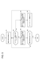
- FIG. 5 is a flowchart for explaining the foreign matter adhesion determination process. It should be noted that the right side sensing system 4R also executes the same foreign matter adhesion determination process.
- step S1 the cleaner control unit 22L starts a foreign matter adhesion determination for determining whether or not foreign matter (raindrops, snow, mud, dust, etc.) is attached to the lamp cover 40L.
- step S2 the cleaner control unit 22L determines whether or not foreign matter is attached to the lamp cover 40L based on the first image data acquired by the first camera 43L.
- the lamp cover 40L is included in the field of view of the first camera 43L. Therefore, when a foreign substance is present in the lamp cover 40L, the presence of the foreign substance can be identified from the first image data.
- the cleaner control unit 22L determines whether or not the pixel value that correlates with the brightness of each pixel constituting the first image data is equal to or greater than a predetermined threshold value.
- the pixel value of a pixel correlates with the brightness of the pixel. That is, the larger the brightness of the pixel, the larger the pixel value of the pixel, while the smaller the brightness of the pixel, the smaller the pixel value of the pixel.
- the cleaner control unit 22L identifies pixels having a pixel value equal to or higher than a predetermined threshold value, and then foreign matter adheres to the lamp cover 40L based on information related to pixels having a pixel value equal to or higher than a predetermined threshold value. Determine if it is present.
- the foreign matter adhesion determination is performed in a situation where the surroundings of the vehicle 1 are dark (for example, at night).
- the surroundings of the vehicle 1 are dark, light is emitted forward from the low beam lighting unit 45L and / or the ADB lighting unit 46L (hereinafter, lighting unit). That is, the light emitted from the lighting unit passes through the lamp cover 40L.
- the light emitted from the lighting unit is reflected by the foreign matter, and then the reflected light is incident on the first camera 43L.
- the pixel value (brightness) of the pixel belonging to the region where the foreign matter exists is higher than the pixel value (brightness) of the pixel belonging to the region where the foreign matter does not exist. growing. In this way, by paying attention to the pixel value of each pixel of the first image data, it is possible to specify the pixel belonging to the region where the foreign matter exists.
- Information related to pixels whose pixel value is equal to or greater than a predetermined threshold includes, for example, 1) the area of a pixel group composed of pixels whose pixel value is equal to or greater than a predetermined threshold, and 2) the area of a pixel group whose pixel value is equal to or greater than a predetermined threshold.
- the cleaner control unit 22L may determine that foreign matter is attached to the lamp cover 40L if the area of the pixel group composed of pixels having a pixel value of a predetermined threshold value or more is a predetermined area or more. .. On the contrary, if the area of the pixel group is smaller than the predetermined area, the cleaner control unit 22L may determine that no foreign matter is attached to the lamp cover 40L. Further, the cleaner control unit 22L may determine that foreign matter is attached to the lamp cover 40L if the number of pixels whose pixel value is equal to or greater than a predetermined threshold value is equal to or greater than a predetermined number.
- the cleaner control unit 22L may determine that no foreign matter is attached to the lamp cover 40L. Further, the cleaner control unit 22L determines that foreign matter is attached to the lamp cover 40L if the ratio of pixels having a pixel value equal to or higher than a predetermined threshold value with respect to all the pixels constituting the first image data is equal to or higher than a predetermined ratio. You may. On the contrary, if the ratio is smaller than the predetermined ratio, the cleaner control unit 22L may determine that no foreign matter is attached to the lamp cover 40L.
- the cleaner control unit 22L determines that foreign matter is attached to the lamp cover 40L (YES in step S2)
- the cleaner control unit 22L transfers the second image data acquired by the second camera 6 to the vehicle control unit 3. Request to do.
- the cleaner control unit 22L receives the second image data from the vehicle control unit 3.
- the lighting unit control unit 23L acquires information on an object such as a vehicle in front (particularly, information on the angular position of the vehicle in front) based on the second image data (step S3).
- the lighting unit control unit 23L irradiates the ADB light distribution pattern PH from the ADB lighting unit 46L so that the object is located in the non-irradiation region PH2 of the ADB light distribution pattern PH.
- the cleaner control unit 22L drives the cover cleaner 47L in order to remove foreign matter adhering to the lamp cover 40L (step S4). After that, the process of determining whether or not foreign matter is attached to the lamp cover (process of step S2) is executed again.
- the lighting unit control unit 23L is based on the first image data acquired by the first camera 43L. Then, information on an object such as a vehicle in front (particularly, information on the angular position of the vehicle in front) is acquired (step S5). After that, the lighting unit control unit 23L irradiates the ADB light distribution pattern PH from the ADB lighting unit 46L so that the object is located in the non-irradiation region PH2 of the ADB light distribution pattern PH.
- step S6 when the cleaner control unit 22L ends the foreign matter adhesion determination (YES in step S6), the cleaner control unit 22L ends a series of processes shown in FIG. On the other hand, if the cleaner control unit 22L does not finish the foreign matter adhesion determination (NO in step S6), the cleaner control unit 22L executes the process of step S2 again.
- the first image data from the first camera 43L arranged in the space SL formed by the lamp cover 40L and the lamp housing 42L is used. Based on this, information regarding the angular position of the object existing outside the vehicle 1 is acquired. After that, the irradiation of the ADB light distribution pattern PH is controlled based on the information regarding the angular position of the object. On the other hand, when a foreign substance adheres to the lamp cover 40L, information on the angular position of the object is acquired based on the second image data from the second camera 6 arranged in the interior of the vehicle 1. ..
- the irradiation of the ADB light distribution pattern PH is controlled based on the information regarding the angular position of the object.
- the left side sensing system 4L capable of preventing a decrease in cognitive accuracy for an object even when a foreign substance is attached to the lamp cover 40L. Further, it is possible to suitably prevent a situation in which glare light is irradiated to the occupants of the vehicle in front.
- the second camera 6 is arranged in the interior of the vehicle 1 so as to face the front window 70, the situation where foreign matter adheres to the second camera 6 is prevented. Further, foreign matter adhering to the front window 70 located in the field of view of the second camera 6 is surely removed by a wiper (not shown) provided on the front window 70. In this way, the situation where a foreign object is reflected in the second image data acquired by the second camera 6 is preferably prevented. Therefore, even when a foreign substance is attached to the lamp cover 40L, the control unit 20L can surely acquire information about the object based on the second image data in which the foreign substance is not reflected.
- control unit 20L can control the irradiation of the ADB light distribution pattern PH so that the vehicle in front is included in the non-irradiation region PH2 of the ADB light distribution pattern PH, so that the occupant of the vehicle in front can receive glare light. It is possible to suitably prevent the situation of giving.
- the lamp cover 40L it is determined whether or not foreign matter is attached to the lamp cover 40L based on the first image data acquired by the first camera 43L. Further, when no foreign matter adheres to the lamp cover 40L, information on an object such as a vehicle in front is acquired based on the first image data. In this way, the first image data can be efficiently utilized to identify the existence of both the object and the foreign substance.
- the lamp cover and the lamp housing are mentioned as examples of the translucent cover and the housing, but the translucent cover and the housing of the present embodiment are not limited thereto.
- the translucent cover and the housing of the rear camera module 43b installed on the rear side of the vehicle 1B may be another example of the translucent cover and the housing.
- the rear camera module 43b is configured to acquire the surrounding environment information indicating the rear region of the vehicle 1B.
- the rear camera module 43b includes a translucent cover, a housing, and a first camera.
- the first camera is arranged in the space formed by the translucent cover and the housing of the rear camera module 43b, and is configured to acquire the first image data.
- a cover cleaner 47b is provided around the rear camera module 43b, and is configured to remove foreign matter adhering to the translucent cover of the rear camera module 43b.
- the second camera 6a for acquiring the second image data is arranged in the room of the vehicle 1B so as to face the rear window 80 of the vehicle 1B.
- the vehicle sensing system 4b is composed of a rear camera module 43b, a cover cleaner 47b, and a control unit (not shown) composed of an ECU.
- the vehicle sensing system 4b may be configured to execute the foreign matter adhesion determination process shown in FIG.
- the vehicle sensing system 4b was acquired by the first image data acquired by the first camera or the second camera 6a according to the determination result of whether or not foreign matter is attached to the translucent cover of the rear camera module 43b. Either one of the second image data is adopted.
- the vehicle sensing system 4b may specify the surrounding environment information indicating the rear region of the vehicle 1B based on either the first image data or the second image data adopted.
- a vehicle sensing system 4b capable of preventing a decrease in cognitive accuracy with respect to surrounding environment information even when a foreign substance adheres to the translucent cover of the rear camera module 43b. ..
- the first camera and the second camera are mentioned as examples of the first sensor and the second sensor, but the first sensor and the second sensor of the present embodiment are limited to the camera. is not it.
- the first LiDAR unit may be adopted instead of the first camera
- the second LiDAR unit may be adopted instead of the second camera.
- the left side sensing system 4L shown in FIG. 3 has the first point cloud data acquired by the first LiDAR unit or the second point acquired by the second LiDAR, depending on the determination result of whether or not foreign matter is attached to the lamp cover 40L. Either one of the group data may be adopted.
- the left side sensing system 4L may specify the surrounding environment information indicating the peripheral region of the vehicle 1 based on either the first point cloud data or the second point cloud data adopted.
- the vehicle sensing system mounted on the vehicle is described, but the sensing system is not limited to the vehicle sensing system.
- the sensing system may be a sensing system for a surveillance camera installed on the road.
- the sensing system for the surveillance camera includes a first surveillance camera unit, a second surveillance camera unit, a control unit, and a cover cleaner.
- the first surveillance camera unit is arranged in the space formed by the translucent cover and the housing, and is configured to acquire the first image data indicating the surrounding environment.
- the second surveillance camera unit is arranged outside the space formed by the translucent cover and the housing, and is configured to acquire the second image data indicating the surrounding environment.
- the control unit is composed of, for example, a microcontroller having a processor and a memory.
- the cover cleaner is provided around the translucent cover and is configured to remove foreign matter adhering to the translucent cover.
- the control unit acquires information on an object such as a pedestrian or a vehicle based on the first image data acquired by the first surveillance camera unit.
- the control unit acquires information about the object based on the second image data acquired by the second surveillance camera unit.
- the sensing system according to the present embodiment sufficiently functions as a sensing system for a surveillance camera.
Landscapes
- Engineering & Computer Science (AREA)
- Physics & Mathematics (AREA)
- General Physics & Mathematics (AREA)
- Radar, Positioning & Navigation (AREA)
- Remote Sensing (AREA)
- Multimedia (AREA)
- Theoretical Computer Science (AREA)
- Computer Networks & Wireless Communication (AREA)
- Electromagnetism (AREA)
- Mechanical Engineering (AREA)
- Software Systems (AREA)
- Traffic Control Systems (AREA)
- Lighting Device Outwards From Vehicle And Optical Signal (AREA)
Abstract
Description
前記センシングシステムの外部に存在する対象物に関する情報を取得するように構成された制御部と、
透光性カバーとハウジングによって形成された空間内に配置され、前記外部の周辺環境を示す第1データを取得するように構成された第1センサと、
前記透光性カバーに付着した異物を除去するように構成されたカバークリーナーと、
を備える。
前記制御部は、
前記透光性カバーに異物が付着しているかどうかを判定し、前記透光性カバーに異物が付着しているとの判定に応じて前記カバークリーナーを駆動させ、
前記透光性カバーに異物が付着していない場合に、前記第1データに基づいて前記対象物に関する情報を取得し、
前記透光性カバーに異物が付着している場合に、前記空間外に配置された第2センサから前記外部の周辺環境を示す第2データを取得した上で、当該取得した第2データに基づいて前記対象物に関する情報を取得する、ように構成されている。
Claims (7)
- センシングシステムであって、
前記センシングシステムの外部に存在する対象物に関する情報を取得するように構成された制御部と、
透光性カバーとハウジングによって形成された空間内に配置され、前記外部の周辺環境を示す第1データを取得するように構成された第1センサと、
前記透光性カバーに付着した異物を除去するように構成されたカバークリーナーと、
を備え、
前記制御部は、
前記透光性カバーに異物が付着しているかどうかを判定し、前記透光性カバーに異物が付着しているとの判定に応じて前記カバークリーナーを駆動させ、
前記透光性カバーに異物が付着していない場合に、前記第1データに基づいて前記対象物に関する情報を取得し、
前記透光性カバーに異物が付着している場合に、前記空間外に配置された第2センサから前記外部の周辺環境を示す第2データを取得した上で、当該取得した第2データに基づいて前記対象物に関する情報を取得する、ように構成されている、センシングシステム。 - 前記空間内に配置されると共に、前記外部に向けて照射領域と非照射領域とを有する配光パターンを出射するように構成された照明ユニットをさらに備え、
前記制御部は、前記対象物が前記配光パターンの非照射領域に含まれるように前記照明ユニットを制御するように構成されている、請求項1に記載のセンシングシステム。 - 前記第1センサは、前記外部の周辺環境を示す第1画像データを取得するように構成された第1カメラであって、
前記制御部は、前記第1画像データに基づいて、前記透光性カバーに異物が付着しているかどうかを判定するように構成されている、請求項1又は2に記載のセンシングシステム。 - 前記制御部は、
前記第1画像データを構成する各ピクセルの輝度と相関する画素値が所定の閾値以上であるかどうかを判定し、
画素値が前記所定の閾値以上のピクセルに関連する情報に基づいて、前記透光性カバーに異物が付着しているかどうかを判定する、ように構成されている、請求項3に記載のセンシングシステム。 - 前記センシングシステムは、車両に設けられており、
前記第2センサは、前記車両の室内に配置されている、請求項1から4のうちいずれか一項に記載のセンシングシステム。 - 前記第2センサは、前記車両のフロントウィンドウ又はリアウィンドウに対向するように配置されている、請求項5に記載のセンシングシステム。
- 請求項1から6のうちいずれか一項に記載のセンシングシステムを備えた車両。
Priority Applications (4)
| Application Number | Priority Date | Filing Date | Title |
|---|---|---|---|
| JP2022544457A JP7681027B2 (ja) | 2020-08-24 | 2021-08-13 | センシングシステム及び車両 |
| EP21861281.0A EP4201757A4 (en) | 2020-08-24 | 2021-08-13 | DETECTION SYSTEM AND VEHICLE |
| US18/042,875 US20230311818A1 (en) | 2020-08-24 | 2021-08-13 | Sensing system and vehicle |
| CN202180052233.4A CN115884904A (zh) | 2020-08-24 | 2021-08-13 | 传感系统及车辆 |
Applications Claiming Priority (2)
| Application Number | Priority Date | Filing Date | Title |
|---|---|---|---|
| JP2020-141045 | 2020-08-24 | ||
| JP2020141045 | 2020-08-24 |
Publications (1)
| Publication Number | Publication Date |
|---|---|
| WO2022044853A1 true WO2022044853A1 (ja) | 2022-03-03 |
Family
ID=80352295
Family Applications (1)
| Application Number | Title | Priority Date | Filing Date |
|---|---|---|---|
| PCT/JP2021/029818 Ceased WO2022044853A1 (ja) | 2020-08-24 | 2021-08-13 | センシングシステム及び車両 |
Country Status (5)
| Country | Link |
|---|---|
| US (1) | US20230311818A1 (ja) |
| EP (1) | EP4201757A4 (ja) |
| JP (1) | JP7681027B2 (ja) |
| CN (1) | CN115884904A (ja) |
| WO (1) | WO2022044853A1 (ja) |
Families Citing this family (3)
| Publication number | Priority date | Publication date | Assignee | Title |
|---|---|---|---|---|
| CN116076078B (zh) * | 2020-09-11 | 2025-04-25 | 株式会社电装 | 车辆控制装置、车辆控制方法、车辆控制程序 |
| KR20240177182A (ko) * | 2023-06-19 | 2024-12-27 | 현대자동차주식회사 | 주행영상기록장치 제어방법 및 주행영상기록장치 |
| DE102024124632A1 (de) * | 2024-08-29 | 2026-03-05 | Zf Cv Systems Global Gmbh | Umfeldsensoreinheit zur Anbringung an einem Kraftfahrzeug |
Citations (7)
| Publication number | Priority date | Publication date | Assignee | Title |
|---|---|---|---|---|
| JP2008068701A (ja) * | 2006-09-13 | 2008-03-27 | Hitachi Ltd | ヘッドランプモジュール |
| JP2019153932A (ja) * | 2018-03-02 | 2019-09-12 | アイシン精機株式会社 | 汚れ報知装置 |
| WO2019221007A1 (ja) * | 2018-05-18 | 2019-11-21 | 株式会社小糸製作所 | 撮像装置、およびランプ装置 |
| US20200023814A1 (en) * | 2018-07-19 | 2020-01-23 | Toyota Motor Engineering & Manufacturing North America, Inc. | Autonomous vehicle glass cleaning system |
| JP2020026248A (ja) | 2018-08-16 | 2020-02-20 | 株式会社小糸製作所 | 前照灯の配光制御システム及び配光制御手段 |
| US20200215972A1 (en) * | 2019-01-04 | 2020-07-09 | Ford Global Technologies, Llc | Low-light sensor cleaning |
| JP2020141045A (ja) | 2019-02-28 | 2020-09-03 | セイコーエプソン株式会社 | 半導体レーザーおよび原子発振器 |
Family Cites Families (10)
| Publication number | Priority date | Publication date | Assignee | Title |
|---|---|---|---|---|
| JP2010014494A (ja) * | 2008-07-02 | 2010-01-21 | Denso Corp | 異物検出装置、異物検出プログラム、異物除去装置、および車載通信装置 |
| KR101518896B1 (ko) * | 2013-10-10 | 2015-05-11 | 현대자동차 주식회사 | 와이퍼 작동 시스템 및 방법 |
| US20180339645A1 (en) * | 2016-06-03 | 2018-11-29 | Faraday&Future Inc. | Automatic adaptive headlight control |
| EP3636490B1 (en) * | 2017-06-09 | 2023-05-24 | Koito Manufacturing Co., Ltd. | Vehicular lamp, and device and method for controlling same |
| WO2019116607A1 (ja) * | 2017-12-12 | 2019-06-20 | 株式会社デンソー | 車両用清掃システム |
| JP7043256B2 (ja) * | 2017-12-28 | 2022-03-29 | 株式会社小糸製作所 | 車両用照明システム及び車両 |
| JP7204674B2 (ja) * | 2017-12-28 | 2023-01-16 | 株式会社小糸製作所 | 車両用照明システム、車両、車車間通信システム及び車両システム |
| US10773717B2 (en) * | 2018-04-12 | 2020-09-15 | Trw Automotive U.S. Llc | Vehicle assist system |
| JP7184539B2 (ja) * | 2018-05-24 | 2022-12-06 | スタンレー電気株式会社 | 点灯制御装置、車両用灯具、および点灯制御方法 |
| DE102018119026A1 (de) * | 2018-08-06 | 2020-02-06 | Knorr-Bremse Systeme für Nutzfahrzeuge GmbH | Kameraüberwachungssystem |
-
2021
- 2021-08-13 WO PCT/JP2021/029818 patent/WO2022044853A1/ja not_active Ceased
- 2021-08-13 CN CN202180052233.4A patent/CN115884904A/zh active Pending
- 2021-08-13 JP JP2022544457A patent/JP7681027B2/ja active Active
- 2021-08-13 US US18/042,875 patent/US20230311818A1/en not_active Abandoned
- 2021-08-13 EP EP21861281.0A patent/EP4201757A4/en not_active Withdrawn
Patent Citations (7)
| Publication number | Priority date | Publication date | Assignee | Title |
|---|---|---|---|---|
| JP2008068701A (ja) * | 2006-09-13 | 2008-03-27 | Hitachi Ltd | ヘッドランプモジュール |
| JP2019153932A (ja) * | 2018-03-02 | 2019-09-12 | アイシン精機株式会社 | 汚れ報知装置 |
| WO2019221007A1 (ja) * | 2018-05-18 | 2019-11-21 | 株式会社小糸製作所 | 撮像装置、およびランプ装置 |
| US20200023814A1 (en) * | 2018-07-19 | 2020-01-23 | Toyota Motor Engineering & Manufacturing North America, Inc. | Autonomous vehicle glass cleaning system |
| JP2020026248A (ja) | 2018-08-16 | 2020-02-20 | 株式会社小糸製作所 | 前照灯の配光制御システム及び配光制御手段 |
| US20200215972A1 (en) * | 2019-01-04 | 2020-07-09 | Ford Global Technologies, Llc | Low-light sensor cleaning |
| JP2020141045A (ja) | 2019-02-28 | 2020-09-03 | セイコーエプソン株式会社 | 半導体レーザーおよび原子発振器 |
Non-Patent Citations (1)
| Title |
|---|
| See also references of EP4201757A4 |
Also Published As
| Publication number | Publication date |
|---|---|
| EP4201757A1 (en) | 2023-06-28 |
| JPWO2022044853A1 (ja) | 2022-03-03 |
| JP7681027B2 (ja) | 2025-05-21 |
| EP4201757A4 (en) | 2024-01-17 |
| US20230311818A1 (en) | 2023-10-05 |
| CN115884904A (zh) | 2023-03-31 |
Similar Documents
| Publication | Publication Date | Title |
|---|---|---|
| JP7254832B2 (ja) | ヘッドアップディスプレイ、車両用表示システム、及び車両用表示方法 | |
| JP7241081B2 (ja) | 車両用表示システム及び車両 | |
| EP3943331B1 (en) | Head-up display for vehicles and head-up display system for vehicles | |
| JP7295863B2 (ja) | 車両用表示システム及び車両 | |
| JP6970612B2 (ja) | 車両用照明システム及び車両 | |
| JP7470230B2 (ja) | 車両用表示システム、車両システム及び車両 | |
| JP7187291B2 (ja) | 赤外線カメラシステム及び車両 | |
| US20200333182A1 (en) | Vehicle lamp | |
| JP7681027B2 (ja) | センシングシステム及び車両 | |
| JPWO2020170680A1 (ja) | 汚れ検出システム、LiDARユニット、車両用センシングシステム及び車両 | |
| CN110944874A (zh) | 车辆用照明系统以及车辆 | |
| CN114466761A (zh) | 平视显示器及图像显示系统 | |
| JPWO2020031917A1 (ja) | 車両用表示システム及び車両 | |
| WO2017073250A1 (ja) | 車両用灯具 | |
| JPWO2020100656A1 (ja) | 赤外線カメラシステム、赤外線カメラモジュール及び車両 | |
| EP4434815A1 (en) | Road surface-marking light and road surface-marking light system | |
| EP4570592A1 (en) | Road surface rendering device | |
| JP7340607B2 (ja) | 車両用照明システム、車両システム及び車両 | |
| WO2020189289A1 (ja) | 車両用灯具および車両用灯具システム | |
| WO2023190338A1 (ja) | 画像照射装置 | |
| CN119734634A (zh) | 一种车灯的控制方法、车灯系统以及车辆 | |
| HK40099893A (zh) | 封装有相机和人工智能处理器以调节照明的自主前照灯 |
Legal Events
| Date | Code | Title | Description |
|---|---|---|---|
| 121 | Ep: the epo has been informed by wipo that ep was designated in this application |
Ref document number: 21861281 Country of ref document: EP Kind code of ref document: A1 |
|
| ENP | Entry into the national phase |
Ref document number: 2022544457 Country of ref document: JP Kind code of ref document: A |
|
| NENP | Non-entry into the national phase |
Ref country code: DE |
|
| ENP | Entry into the national phase |
Ref document number: 2021861281 Country of ref document: EP Effective date: 20230324 |
|
| WWW | Wipo information: withdrawn in national office |
Ref document number: 2021861281 Country of ref document: EP |