WO2022044861A1 - 電池モジュール、電池モジュールの使用方法及び電池セルの製造方法 - Google Patents
電池モジュール、電池モジュールの使用方法及び電池セルの製造方法 Download PDFInfo
- Publication number
- WO2022044861A1 WO2022044861A1 PCT/JP2021/029867 JP2021029867W WO2022044861A1 WO 2022044861 A1 WO2022044861 A1 WO 2022044861A1 JP 2021029867 W JP2021029867 W JP 2021029867W WO 2022044861 A1 WO2022044861 A1 WO 2022044861A1
- Authority
- WO
- WIPO (PCT)
- Prior art keywords
- electrode
- separator
- battery
- negative electrode
- battery module
- Prior art date
- Legal status (The legal status is an assumption and is not a legal conclusion. Google has not performed a legal analysis and makes no representation as to the accuracy of the status listed.)
- Ceased
Links
Images




Classifications
-
- H—ELECTRICITY
- H01—ELECTRIC ELEMENTS
- H01M—PROCESSES OR MEANS, e.g. BATTERIES, FOR THE DIRECT CONVERSION OF CHEMICAL ENERGY INTO ELECTRICAL ENERGY
- H01M10/00—Secondary cells; Manufacture thereof
- H01M10/05—Accumulators with non-aqueous electrolyte
- H01M10/058—Construction or manufacture
- H01M10/0583—Construction or manufacture of accumulators with folded construction elements except wound ones, i.e. folded positive or negative electrodes or separators, e.g. with "Z"-shaped electrodes or separators
-
- H—ELECTRICITY
- H01—ELECTRIC ELEMENTS
- H01M—PROCESSES OR MEANS, e.g. BATTERIES, FOR THE DIRECT CONVERSION OF CHEMICAL ENERGY INTO ELECTRICAL ENERGY
- H01M50/00—Constructional details or processes of manufacture of the non-active parts of electrochemical cells other than fuel cells, e.g. hybrid cells
- H01M50/40—Separators; Membranes; Diaphragms; Spacing elements inside cells
- H01M50/463—Separators, membranes or diaphragms characterised by their shape
- H01M50/466—U-shaped, bag-shaped or folded
-
- H—ELECTRICITY
- H01—ELECTRIC ELEMENTS
- H01M—PROCESSES OR MEANS, e.g. BATTERIES, FOR THE DIRECT CONVERSION OF CHEMICAL ENERGY INTO ELECTRICAL ENERGY
- H01M10/00—Secondary cells; Manufacture thereof
- H01M10/04—Construction or manufacture in general
-
- H—ELECTRICITY
- H01—ELECTRIC ELEMENTS
- H01M—PROCESSES OR MEANS, e.g. BATTERIES, FOR THE DIRECT CONVERSION OF CHEMICAL ENERGY INTO ELECTRICAL ENERGY
- H01M10/00—Secondary cells; Manufacture thereof
- H01M10/04—Construction or manufacture in general
- H01M10/0459—Cells or batteries with folded separator between plate-like electrodes
-
- H—ELECTRICITY
- H01—ELECTRIC ELEMENTS
- H01M—PROCESSES OR MEANS, e.g. BATTERIES, FOR THE DIRECT CONVERSION OF CHEMICAL ENERGY INTO ELECTRICAL ENERGY
- H01M10/00—Secondary cells; Manufacture thereof
- H01M10/05—Accumulators with non-aqueous electrolyte
- H01M10/052—Li-accumulators
-
- H—ELECTRICITY
- H01—ELECTRIC ELEMENTS
- H01M—PROCESSES OR MEANS, e.g. BATTERIES, FOR THE DIRECT CONVERSION OF CHEMICAL ENERGY INTO ELECTRICAL ENERGY
- H01M50/00—Constructional details or processes of manufacture of the non-active parts of electrochemical cells other than fuel cells, e.g. hybrid cells
- H01M50/10—Primary casings; Jackets or wrappings
- H01M50/102—Primary casings; Jackets or wrappings characterised by their shape or physical structure
- H01M50/103—Primary casings; Jackets or wrappings characterised by their shape or physical structure prismatic or rectangular
-
- H—ELECTRICITY
- H01—ELECTRIC ELEMENTS
- H01M—PROCESSES OR MEANS, e.g. BATTERIES, FOR THE DIRECT CONVERSION OF CHEMICAL ENERGY INTO ELECTRICAL ENERGY
- H01M50/00—Constructional details or processes of manufacture of the non-active parts of electrochemical cells other than fuel cells, e.g. hybrid cells
- H01M50/10—Primary casings; Jackets or wrappings
- H01M50/102—Primary casings; Jackets or wrappings characterised by their shape or physical structure
- H01M50/105—Pouches or flexible bags
-
- H—ELECTRICITY
- H01—ELECTRIC ELEMENTS
- H01M—PROCESSES OR MEANS, e.g. BATTERIES, FOR THE DIRECT CONVERSION OF CHEMICAL ENERGY INTO ELECTRICAL ENERGY
- H01M50/00—Constructional details or processes of manufacture of the non-active parts of electrochemical cells other than fuel cells, e.g. hybrid cells
- H01M50/20—Mountings; Secondary casings or frames; Racks, modules or packs; Suspension devices; Shock absorbers; Transport or carrying devices; Holders
- H01M50/204—Racks, modules or packs for multiple batteries or multiple cells
-
- H—ELECTRICITY
- H01—ELECTRIC ELEMENTS
- H01M—PROCESSES OR MEANS, e.g. BATTERIES, FOR THE DIRECT CONVERSION OF CHEMICAL ENERGY INTO ELECTRICAL ENERGY
- H01M50/00—Constructional details or processes of manufacture of the non-active parts of electrochemical cells other than fuel cells, e.g. hybrid cells
- H01M50/20—Mountings; Secondary casings or frames; Racks, modules or packs; Suspension devices; Shock absorbers; Transport or carrying devices; Holders
- H01M50/204—Racks, modules or packs for multiple batteries or multiple cells
- H01M50/207—Racks, modules or packs for multiple batteries or multiple cells characterised by their shape
- H01M50/209—Racks, modules or packs for multiple batteries or multiple cells characterised by their shape adapted for prismatic or rectangular cells
-
- H—ELECTRICITY
- H01—ELECTRIC ELEMENTS
- H01M—PROCESSES OR MEANS, e.g. BATTERIES, FOR THE DIRECT CONVERSION OF CHEMICAL ENERGY INTO ELECTRICAL ENERGY
- H01M50/00—Constructional details or processes of manufacture of the non-active parts of electrochemical cells other than fuel cells, e.g. hybrid cells
- H01M50/30—Arrangements for facilitating escape of gases
- H01M50/394—Gas-pervious parts or elements
-
- H—ELECTRICITY
- H01—ELECTRIC ELEMENTS
- H01M—PROCESSES OR MEANS, e.g. BATTERIES, FOR THE DIRECT CONVERSION OF CHEMICAL ENERGY INTO ELECTRICAL ENERGY
- H01M50/00—Constructional details or processes of manufacture of the non-active parts of electrochemical cells other than fuel cells, e.g. hybrid cells
- H01M50/40—Separators; Membranes; Diaphragms; Spacing elements inside cells
- H01M50/46—Separators, membranes or diaphragms characterised by their combination with electrodes
-
- H—ELECTRICITY
- H01—ELECTRIC ELEMENTS
- H01M—PROCESSES OR MEANS, e.g. BATTERIES, FOR THE DIRECT CONVERSION OF CHEMICAL ENERGY INTO ELECTRICAL ENERGY
- H01M50/00—Constructional details or processes of manufacture of the non-active parts of electrochemical cells other than fuel cells, e.g. hybrid cells
- H01M50/40—Separators; Membranes; Diaphragms; Spacing elements inside cells
- H01M50/463—Separators, membranes or diaphragms characterised by their shape
-
- H—ELECTRICITY
- H01—ELECTRIC ELEMENTS
- H01M—PROCESSES OR MEANS, e.g. BATTERIES, FOR THE DIRECT CONVERSION OF CHEMICAL ENERGY INTO ELECTRICAL ENERGY
- H01M2220/00—Batteries for particular applications
- H01M2220/20—Batteries in motive systems, e.g. vehicle, ship, plane
-
- Y—GENERAL TAGGING OF NEW TECHNOLOGICAL DEVELOPMENTS; GENERAL TAGGING OF CROSS-SECTIONAL TECHNOLOGIES SPANNING OVER SEVERAL SECTIONS OF THE IPC; TECHNICAL SUBJECTS COVERED BY FORMER USPC CROSS-REFERENCE ART COLLECTIONS [XRACs] AND DIGESTS
- Y02—TECHNOLOGIES OR APPLICATIONS FOR MITIGATION OR ADAPTATION AGAINST CLIMATE CHANGE
- Y02E—REDUCTION OF GREENHOUSE GAS [GHG] EMISSIONS, RELATED TO ENERGY GENERATION, TRANSMISSION OR DISTRIBUTION
- Y02E60/00—Enabling technologies; Technologies with a potential or indirect contribution to GHG emissions mitigation
- Y02E60/10—Energy storage using batteries
-
- Y—GENERAL TAGGING OF NEW TECHNOLOGICAL DEVELOPMENTS; GENERAL TAGGING OF CROSS-SECTIONAL TECHNOLOGIES SPANNING OVER SEVERAL SECTIONS OF THE IPC; TECHNICAL SUBJECTS COVERED BY FORMER USPC CROSS-REFERENCE ART COLLECTIONS [XRACs] AND DIGESTS
- Y02—TECHNOLOGIES OR APPLICATIONS FOR MITIGATION OR ADAPTATION AGAINST CLIMATE CHANGE
- Y02P—CLIMATE CHANGE MITIGATION TECHNOLOGIES IN THE PRODUCTION OR PROCESSING OF GOODS
- Y02P70/00—Climate change mitigation technologies in the production process for final industrial or consumer products
- Y02P70/50—Manufacturing or production processes characterised by the final manufactured product
Definitions
- the present invention relates to a battery module, a method of using the battery module, and a method of manufacturing a battery cell.
- non-aqueous electrolyte battery cells such as lithium ion secondary battery cells have been developed.
- the battery cell includes a positive electrode, a negative electrode, and a separator.
- the separator is stretched while passing between the adjacent positive electrode and the negative electrode and being folded back.
- the folded portion of the separator covers the ends of the electrodes such as the positive electrode and the negative electrode.
- the gas generated from the electrode may stay in the vicinity of the end of the electrode covered with the folded portion of the separator.
- the stagnant gas may hinder the reaction of the battery between the positive electrode and the negative electrode.
- the capacity of the battery may decrease, and there may be a risk of ignition of the battery due to Li precipitation or the like.
- contaminants such as metals pushed up by the gas may adhere to the ends of the electrodes and precipitate.
- An example of an object of the present invention is to make it easier for gas generated from an electrode to escape from a separator.
- Other objects of the invention will become apparent from the description herein.
- One aspect of the present invention is Accommodating members and A plurality of battery cells housed in the housing member, Equipped with Each of the plurality of battery cells is a separator that passes between the first electrode, the second electrode having a larger area than the first electrode, and the adjacent first electrode and the second electrode, and extends while being folded back. And have, In any of the plurality of battery cells, the folded portion of the separator covers the portion on the same side of the second electrode, which is a battery module.
- Another aspect of the present invention is It passes between the accommodating member, the first electrode accommodated in the accommodating member, the second electrode having a larger area than the first electrode, and the adjacent first electrode and the second electrode, and stretches while being folded back.
- a method of using a battery module comprising a separator and a plurality of battery cells.
- the method of using the battery module includes a step of using the battery module in a state where the folded portion of the separator covers the portion on the same side of the second electrode.
- Yet another aspect of the invention is A step of wrapping a first electrode, a second electrode having a larger area than the first electrode, and a separator that passes between the adjacent first electrode and the second electrode and stretches while folding back, with an exterior material. , A step of removing gas inside the exterior material while the folded portion of the separator covers the upper portion of the second electrode. Is a method for manufacturing a battery cell.
- the gas generated from the electrode can be easily released from the separator.
- FIG. 3 is a cross-sectional view taken along the line AA'in FIG. It is sectional drawing of the battery cell which concerns on a comparative example. It is a figure for demonstrating an example of the manufacturing method of the battery cell which concerns on embodiment. It is a top view of the battery cell which concerns on a modification.
- FIG. 1 is a perspective view of the battery module 20 according to the embodiment.
- FIG. 2 is a perspective view of a plurality of battery cells 10 housed in the housing member 200 shown in FIG.
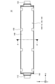
- FIG. 3 is a plan view of the battery cell 10 shown in FIG.
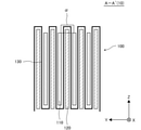
- FIG. 4 is a cross-sectional view taken along the line AA'of FIG.
- the first direction X indicates the length direction of the battery cell 10.
- the positive direction of the first direction X which is the direction indicated by the arrow indicating the first direction X, is the direction from the positive electrode lead 112 to the negative electrode lead 122, which will be described later.
- the negative direction of the first direction X which is the direction opposite to the direction indicated by the arrow indicating the first direction X, is the direction from the negative electrode lead 122 toward the positive electrode lead 112.
- the second direction Y intersects the first direction X, specifically, is orthogonal to each other, and indicates the thickness direction of the battery cell 10.
- the third direction Z intersects and is orthogonal to both the first direction X and the second direction Y, and indicates the width direction of the battery cell 10 and the height direction of the battery module 20.
- the positive direction of the third direction Z which is the direction indicated by the arrow indicating the third direction Z, indicates the upward direction in the vertical direction.
- the negative direction of the third direction Z which is the opposite direction of the direction indicated by the arrow indicating the third direction Z, indicates the downward direction in the vertical direction.
- the white circle with X indicating the second direction Y the direction from the front to the back of the paper surface is the positive direction of the second direction Y, and the direction from the back to the front of the paper surface is the third direction Z. It shows that it is in the positive direction.
- the battery module 20 will be described with reference to FIGS. 1 and 2.
- the battery module 20 includes a plurality of battery cells 10 and an accommodating member 200.
- the plurality of battery cells 10 are housed in the housing member 200. Further, the plurality of battery cells 10 are arranged in one direction, specifically, in the second direction Y.
- the accommodating member 200 is, for example, a housing made of metal or resin.
- each battery cell 10 has a positive electrode lead 112, a negative electrode lead 122, an exterior material 140, and a plurality of fixing members 150.
- the positive electrode lead 112 and the negative electrode lead 122 are provided on both sides of the battery cell 10 in the first direction X. Both the positive electrode lead 112 and the negative electrode lead 122 may be provided at the end of the battery cell 10 on the positive direction side or the negative direction side of the first direction X.
- the exterior material 140 encloses the laminate 100 including the positive electrode 110, the negative electrode 120, and the separator 130 shown in FIG. 4, which will be described later, together with the electrolytic solution.
- Fixing members 150 such as insulating tapes are provided on both sides of the exterior material 140 extending in the first direction X.
- the battery cell 10 will be described with reference to FIGS. 3 and 4.
- the battery cell 10 is a lithium ion secondary battery.
- the battery cell 10 has a laminated body 100.
- the laminate 100 includes a plurality of positive electrode electrodes 110, a plurality of negative electrode electrodes 120, and a separator 130.
- the positive electrode 110 is the first electrode
- the negative electrode 120 is the second electrode having a larger area than the first electrode.
- Each positive electrode 110 and each negative electrode 120 has a thickness in the second direction Y.
- the area of the positive electrode 110 or the negative electrode 120 is the area when the positive electrode 110 or the negative electrode 120 is viewed from the positive direction or the negative direction of the second direction Y.
- the plurality of positive electrode electrodes 110 and the plurality of negative electrode electrodes 120 are alternately arranged along the one direction, specifically, the second direction Y.
- the separator 130 passes between the adjacent positive electrode 110 and the negative electrode 120 and extends while being folded back.
- the folded portion of the separator 130 covers the portion of the negative electrode 120 on the same side. Specifically, the folded portion of the separator 130 covers the upper portion of the negative electrode electrode 120.
- the exterior material 140 has a portion that covers the laminated body 100 from the positive direction side of the second direction Y and a portion that covers the laminated body 100 from the negative direction side of the second direction Y. These portions of the exterior material 140 are formed along two sides of the first direction X of the laminate 100 on the positive direction side and the negative direction side and two sides of the third direction Z on the positive direction side and the negative direction side.
- the sealing portion 142 is formed by being bonded to each other. Further, a plurality of fixing members 150 are provided along one side of the laminated body 100 on the positive direction side of the third direction Z and one side of the laminated body 100 on the negative direction side of the third direction Z.
- FIG. 5 is a cross-sectional view of the battery cell 10K according to the comparative example.
- the battery cell 10K according to the comparative example is the same as the battery cell 10 according to the embodiment except for the following points.
- the battery cell 10K has a laminated body 100K.
- the laminate 100K includes a plurality of positive electrode 110s, a plurality of negative electrode electrodes 120, and a separator 130K.
- the folded portion of the separator 130K covers the upper portion of the positive electrode electrode 110.
- a case where gas is generated from the positive electrode 110 and the negative electrode 120 will be examined.
- the gas is generated by the use of the battery cell 10, for example, charging.
- the gas generated from the positive electrode 110 rises in the electrolytic solution due to buoyancy.
- the upper portion of the positive electrode 110 is not covered by the separator 130. Therefore, the gas can escape above the positive electrode 110 without having to pass through the separator 130.
- both sides of the folded portion of the separator 130 that covers the upper portion of the negative electrode 120 in the second direction Y are not covered by the positive electrode 110. Therefore, as compared with the case where both sides of the second direction Y of the folded portion covering the upper portion of the negative electrode electrode 120 of the separator 130 are covered by the positive electrode 110, the gas generated from the negative electrode 120 is the separator 130. Of these, the folded portion covering the upper portion of the negative electrode electrode 120 is easily transmitted, and the separator 130 is easily pulled out above the folded portion.
- both sides of the folded portion of the separator 130K that covers the upper portion of the positive electrode 110 in the second direction Y are covered by the negative electrode 120. Therefore, the gas generated from the positive electrode 110 is the gas generated from the separator 130K as compared with the case where both sides of the second direction Y of the folded portion covering the upper portion of the positive electrode 110 in the separator 130K are not covered by the negative electrode 120. Of these, it is difficult for the folded portion that covers the upper portion of the positive electrode electrode 110 to pass through, and it is difficult for the separator 130K to come out above the folded portion.
- the gas generated from the positive electrode 110 is difficult to escape above the folded portion of the separator 130K that covers the upper portion of the positive electrode 110. Therefore, in the comparative example, the gas generated from the positive electrode 110 may stay in the vicinity of the upper portion of the positive electrode 110, and the reaction of the battery cell 10K between the positive electrode 110 and the negative electrode 120 may be hindered. .. As a result, the capacity of the battery cell 10K may decrease, and there may be a risk of ignition of the battery cell 10K due to Li precipitation or the like.
- the gas generated from the negative electrode electrode 120 easily escapes above the folded portion of the separator 130 that covers the upper portion of the negative electrode electrode 120. There is. Therefore, in the embodiment, as compared with the comparative example, the gas generated from the negative electrode electrode 120 inhibits the reaction of the battery cell 10 between the positive electrode 110 and the negative electrode 120, and the contaminant such as metal is the negative electrode. Precipitation on the surface of the upper portion of the electrode 120 can be suppressed.
- the folded portion of the separator 130 covers the portion on the same side of the negative electrode electrode 120. Specifically, in any of the plurality of battery cells 10, the folded portion of the separator 130 covers the upper portion of the negative electrode electrode 120. Therefore, in any of the plurality of battery cells 10, the gas generated from the negative electrode electrode 120 is likely to escape from the separator 130.
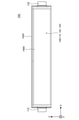
- FIG. 6 is a diagram for explaining an example of a method for manufacturing the battery cell 10 according to the embodiment.
- the positive electrode 110, the negative electrode 120, and the separator 130 that passes between the adjacent positive electrode 110 and the negative electrode 120 and is stretched while being folded back are wrapped by the exterior material 140.
- the exterior material 140 has a portion that covers the laminated body 100 from the positive direction side of the second direction Y and a portion that covers the laminated body 100 from the negative direction side of the second direction Y. These portions of the exterior material 140 are one side on the negative direction side of the third direction Z of the laminated body 100, one side on the negative direction side of the first direction X of the laminated body 100, and the third direction Z from the one side.
- the sealing portion 142 is formed by being bonded to each other.
- the electrolytic solution is injected into the exterior material 140.
- the first sealing portion 142a is formed on the portion of the exterior material 140 that is separated from one side of the laminated body 100 on the positive direction side in the third direction Z by laminating such as welding. As a result, the laminated body 100 is sealed by the exterior material 140.
- the gas inside the exterior material 140 is removed while the folded portion of the separator 130 covers the upper portion of the negative electrode electrode 120.
- the gas generated inside the exterior material 140 by the initial charge is discharged to the first hole 144a formed in the vicinity of the laminated body 100 in the third direction Z from the first sealing portion 142a. Pull out from.
- the first hole 144a is formed after the first sealing portion 142a is formed.
- the first hole 144a is formed at the timing when the gas is desired to be removed, for example, after the gas is generated by the initial charge.
- the timing at which the first hole 144a is formed is not limited to this example.
- the second sealing portion 142b is formed in the vicinity of the laminated body 100 in the third direction Z from the first hole 144a of the exterior material 140 by laminating such as welding.
- the gas generated inside the exterior material 140 generated by aging is removed from the second hole 144b formed in the vicinity of the laminated body 100 in the third direction Z from the second sealing portion 142b.
- the second hole 144b is formed after the second sealing portion 142b is formed.
- the second hole 144b is formed at the timing when the gas is desired to be discharged, for example, after the gas is generated by aging.
- the timing at which the second hole 144b is formed is not limited to this example.
- the third sealing portion 142c is formed by laminating such as welding along one side of the laminated body 100 on the positive direction side of the third direction Z.
- the exterior material 140 is cut along the cut line 146. As a result, the battery cell 10 is manufactured.
- the folded portion of the separator 130 may cover the upper portion of the negative electrode electrode 120 as described with reference to FIG. can. Thereby, the gas generated from the negative electrode electrode 120 by the initial charge or aging can be easily discharged from the separator 130.
- FIG. 7 is a plan view of the battery cell 10A according to the modified example.
- the battery cell 10A according to the modified example is the same as the battery cell 10 according to the embodiment except for the following points.
- the exterior material 140A is folded back on the negative direction side of the third direction Z of the laminated body 100. Further, the portions of the exterior material 140A that cover the laminated body 100 from both the positive direction and the negative direction of the second direction Y are bonded to each other by welding or the like, and the positive direction side of the third direction Z of the laminated body 100
- the sealing portion 142A is formed along one side of the above and two sides of the first direction X on the positive direction and the negative direction side. Also in this modification, the gas generated from the negative electrode electrode 120 can easily escape from the separator 130 as in the embodiment.
- the gas inside the exterior material 140 is in a state where the folded portion of the separator 130 covers the upper portion of the negative electrode electrode 120 in the same manner as in the example described with reference to FIG. Can be pulled out.
- the battery cell 10A may be roll-pressed after degassing. The roll press allows the gas to be expelled into the excess space around the laminate 100. Further, the gas may be further discharged through the holes formed in the exterior material 140A.
- the area of the negative electrode 120 is larger than the area of the positive electrode 110.
- the area of the positive electrode 110 may be larger than the area of the negative electrode 120. In this case, the gas generated from the positive electrode 110 can be easily discharged from the separator 130.
- the battery module 20 according to the embodiment is used in a state where the folded portion of the separator 130 covers the same side portion of the negative electrode electrode 120, for example, the upper portion of the negative electrode electrode 120 in any of the plurality of battery cells 10. May be done. In this case, the gas generated by the use of the battery cell 10 can be easily released from the separator 130.
- Battery cell 10 Battery cell 10A Battery cell 10K Battery cell 20 Battery module 100 Laminated body 100K Laminated body 110 Positive electrode 112 Positive electrode lead 120 Negative electrode 122 Negative electrode lead 130 Separator 130K Separator 140 Exterior material 140A Exterior material 142 Sealing part 142A Sealing part 142a First 1 Sealing part 142b 2nd sealing part 142c 3rd sealing part 144a 1st hole 144b 2nd hole 146 Cut line 150 Fixing member 200 Accommodating member X 1st direction Y 2nd direction Z 3rd direction
Landscapes
- Chemical & Material Sciences (AREA)
- Chemical Kinetics & Catalysis (AREA)
- Electrochemistry (AREA)
- General Chemical & Material Sciences (AREA)
- Engineering & Computer Science (AREA)
- Manufacturing & Machinery (AREA)
- Secondary Cells (AREA)
- Cell Separators (AREA)
Abstract
正極電極(110)は、第1電極となっており、負極電極(120)は、第1電極より面積が大きい第2電極となっている。セパレータ(130)は、隣り合う正極電極(110)と負極電極(120)との間を通過して折り返しながら延伸している。複数の電池セル(10)のいずれにおいても、セパレータ(130)の折り返し部分が負極電極(120)の同じ側の部分を覆っている。具体的には、複数の電池セル(10)のいずれにおいても、セパレータ(130)の折り返し部分が負極電極(120)の上側部分を覆っている。
Description
本発明は、電池モジュール、電池モジュールの使用方法及び電池セルの製造方法に関する。
近年、リチウムイオン二次電池セル等の非水電解質電池セルが開発されている。電池セルは、正極電極、負極電極及びセパレータを備えている。例えば特許文献1に記載されているように、セパレータは、隣り合う正極電極と負極電極との間を通過して折り返しながら延伸している。
セパレータが隣り合う正極電極と負極電極との間を通過して折り返しながら延伸している場合、セパレータの折り返し部分が正極電極、負極電極等の電極の端部を覆っている。この場合、電極から発生したガスが、電極のうちセパレータの折り返し部分で覆われている端部の近傍に滞留する場合がある。滞留したガスによって、正極電極と負極電極との間での電池の反応が阻害される場合がある。これによって、電池の容量が低下し得るとともに、Li析出等によって電池の発火のリスクが生じ得る。また、ガスによって押し上げられた金属等の汚染物質が電極の端部に付着して析出する場合がある。
本発明の目的の一例は、電極から発生するガスをセパレータから抜けやすくすることにある。本発明の他の目的は、本明細書の記載から明らかになるであろう。
本発明の一態様は、
収容部材と、
前記収容部材に収容された複数の電池セルと、
を備え、
前記複数の電池セルの各々は、第1電極と、前記第1電極より面積が大きい第2電極と、隣り合う前記第1電極と前記第2電極との間を通過して折り返しながら延伸するセパレータと、を有しており、
前記複数の電池セルのいずれにおいても、前記セパレータの折り返し部分が前記第2電極の同じ側の部分を覆っている、電池モジュールである。
収容部材と、
前記収容部材に収容された複数の電池セルと、
を備え、
前記複数の電池セルの各々は、第1電極と、前記第1電極より面積が大きい第2電極と、隣り合う前記第1電極と前記第2電極との間を通過して折り返しながら延伸するセパレータと、を有しており、
前記複数の電池セルのいずれにおいても、前記セパレータの折り返し部分が前記第2電極の同じ側の部分を覆っている、電池モジュールである。
本発明の他の一態様は、
収容部材と、前記収容部材に収容され、第1電極と、前記第1電極より面積が大きい第2電極と、隣り合う前記第1電極と前記第2電極との間を通過して折り返しながら延伸するセパレータと、を有する複数の電池セルと、を備える電池モジュールの使用方法であって、
前記複数の電池セルのいずれにおいても、前記セパレータの折り返し部分が前記第2電極の同じ側の部分を覆う状態で、前記電池モジュールを使用する工程を備える、電池モジュールの使用方法である。
収容部材と、前記収容部材に収容され、第1電極と、前記第1電極より面積が大きい第2電極と、隣り合う前記第1電極と前記第2電極との間を通過して折り返しながら延伸するセパレータと、を有する複数の電池セルと、を備える電池モジュールの使用方法であって、
前記複数の電池セルのいずれにおいても、前記セパレータの折り返し部分が前記第2電極の同じ側の部分を覆う状態で、前記電池モジュールを使用する工程を備える、電池モジュールの使用方法である。
本発明のさらに他の一態様は、
第1電極と、前記第1電極より面積が大きい第2電極と、隣り合う前記第1電極と前記第2電極との間を通過して折り返しながら延伸するセパレータと、を外装材によって包む工程と、
前記セパレータの折り返し部分が前記第2電極の上側部分を覆う状態で、前記外装材の内部のガスを抜く工程と、
を備える、電池セルの製造方法である。
第1電極と、前記第1電極より面積が大きい第2電極と、隣り合う前記第1電極と前記第2電極との間を通過して折り返しながら延伸するセパレータと、を外装材によって包む工程と、
前記セパレータの折り返し部分が前記第2電極の上側部分を覆う状態で、前記外装材の内部のガスを抜く工程と、
を備える、電池セルの製造方法である。
本発明の上記一態様によれば、電極から発生するガスをセパレータから抜けやすくすることができる。
以下、本発明の実施の形態について、図面を用いて説明する。なお、すべての図面において、同様な構成要素には同様の符号を付し、適宜説明を省略する。
図1は、実施形態に係る電池モジュール20の斜視図である。図2は、図1に示した収容部材200に収容された複数の電池セル10の斜視図である。図3は、図2に示した電池セル10の平面図である。図4は、図3のA-A´断面図である。
図1~図4において、第1方向Xは、電池セル10の長さ方向を示している。第1方向Xを示す矢印によって示される方向である第1方向Xの正方向は、後述する正極リード112から負極リード122に向かう方向である。第1方向Xを示す矢印によって示される方向の反対方向である第1方向Xの負方向は、負極リード122から正極リード112に向かう方向である。第2方向Yは、第1方向Xに交差、具体的には直交しており、電池セル10の厚み方向を示している。第3方向Zは、第1方向X及び第2方向Yの双方に交差、具体的には直交しており、電池セル10の幅方向及び電池モジュール20の高さ方向を示している。第3方向Zを示す矢印によって示される方向である第3方向Zの正方向は、鉛直方向の上方向を示している。第3方向Zを示す矢印によって示される方向の反対方向である第3方向Zの負方向は、鉛直方向の下方向を示している。また、図3において、第2方向Yを示すX付き白丸は、紙面の手前から奥に向かう方向が第2方向Yの正方向であり、紙面の奥から手前に向かう方向が第3方向Zの正方向であることを示している。図4において、第1方向Xを示すX付き白丸は、紙面の手前から奥に向かう方向が第1方向Xの正方向であり、紙面の奥から手前に向かう方向が第1方向Xの負方向であることを示している。後述する図5~図7においても同様である。
図1及び図2を用いて、電池モジュール20について説明する。
電池モジュール20は、複数の電池セル10及び収容部材200を備えている。複数の電池セル10は、収容部材200に収容されている。また、複数の電池セル10は、一方向、具体的には第2方向Yに並んでいる。収容部材200は、例えば、金属又は樹脂からなる筐体である。図2に示すように、各電池セル10は、正極リード112、負極リード122、外装材140及び複数の固定部材150を有している。正極リード112及び負極リード122は、電池セル10の第1方向Xの両側に設けられている。なお、正極リード112及び負極リード122は、双方とも、電池セル10の第1方向Xの正方向側又は負方向側の端部に設けられていてもよい。外装材140は、後述する図4に示す正極電極110、負極電極120及びセパレータ130を含む積層体100を電解液とともに包んでいる。外装材140のうちの第1方向Xに延伸する両辺には、例えば絶縁テープ等の固定部材150が設けられている。
図3及び図4を用いて、電池セル10について説明する。本実施形態において、電池セル10は、リチウムイオン二次電池である。
電池セル10は、積層体100を有している。積層体100は、複数の正極電極110、複数の負極電極120及びセパレータ130を含んでいる。本実施形態において、正極電極110は、第1電極となっており、負極電極120は、第1電極より面積が大きい第2電極となっている。各正極電極110及び各負極電極120は、第2方向Yに厚みを有している。なお、正極電極110又は負極電極120の面積とは、正極電極110又は負極電極120を第2方向Yの正方向又は負方向から見たときの面積である。
図4に示すように、複数の正極電極110及び複数の負極電極120は、上記一方向、具体的には第2方向Yに沿って交互に並んでいる。セパレータ130は、隣り合う正極電極110と負極電極120との間を通過して折り返しながら延伸している。セパレータ130の折り返し部分は負極電極120の同じ側の部分を覆っている。具体的には、セパレータ130の折り返し部分は負極電極120の上側部分を覆っている。
外装材140は、積層体100を第2方向Yの正方向側から覆う部分と、積層体100を第2方向Yの負方向側から覆う部分と、を有している。外装材140のこれらの部分は、積層体100の第1方向Xの正方向側及び負方向側の2辺と、第3方向Zの正方向側及び負方向側の2辺と、に沿って互いに貼り合わされて封止部142が形成されている。また、積層体100の第3方向Zの正方向側の1辺と、積層体100の第3方向Zの負方向側の1辺と、に沿って複数の固定部材150が設けられている。
図5は、比較例に係る電池セル10Kの断面図である。比較例に係る電池セル10Kは、以下の点を除いて、実施形態に係る電池セル10と同様である。
電池セル10Kは、積層体100Kを有している。積層体100Kは、複数の正極電極110、複数の負極電極120及びセパレータ130Kを含んでいる。電池セル10Kでは、セパレータ130Kの折り返し部分が正極電極110の上側部分を覆っている。
図4に示した実施形態において、正極電極110及び負極電極120からガスが発生した場合を検討する。当該ガスは、例えば充電等、電池セル10の使用によって発生する。正極電極110から発生したガスは浮力によって電解液内を上昇する。正極電極110の上側部分はセパレータ130によって覆われていない。このため、ガスはセパレータ130を透過する必要なく正極電極110の上方へ抜けていくことができる。これに対して、負極電極120から発生したガスが負極電極120の上方へ抜けていくためには、破線で囲まれた領域α等、セパレータ130のうち負極電極120の上側部分を覆う折り返し部分を透過する必要がある。実施形態では、セパレータ130のうち負極電極120の上側部分を覆う折り返し部分の第2方向Yの両側は、正極電極110によって覆われていない。したがって、セパレータ130のうち負極電極120の上側部分を覆う折り返し部分の第2方向Yの両側が正極電極110によって覆われている場合と比較して、負極電極120から発生したガスは、セパレータ130のうち負極電極120の上側部分を覆う折り返し部分を透過しやすくなっており、セパレータ130の当該折り返し部分の上方へ抜けやすくなっている。
図5に示した比較例において、正極電極110及び負極電極120からガスが発生した場合を検討する。負極電極120から発生したガスは浮力によって電解液内を上昇する。負極電極120の上側部分はセパレータ130Kによって覆われていない。このため、ガスはセパレータ130Kを透過する必要なく負極電極120の上方へ抜けていくことができる。これに対して、正極電極110から発生したガスが正極電極110の上方へ抜けていくためには、破線で囲まれた領域β等、セパレータ130Kのうち正極電極110の上側部分を覆う折り返し部分を透過する必要がある。しかしながら、比較例では、セパレータ130Kのうち正極電極110の上側部分を覆う折り返し部分の第2方向Yの両側が負極電極120によって覆われている。したがって、セパレータ130Kのうち正極電極110の上側部分を覆う折り返し部分の第2方向Yの両側が負極電極120によって覆われていない場合と比較して、正極電極110から発生したガスは、セパレータ130Kのうち正極電極110の上側部分を覆う折り返し部分を透過しにくくなっており、セパレータ130Kの当該折り返し部分の上方へ抜けにくくなっている。
図5に示した比較例においては、上述したように、正極電極110から発生したガスが、セパレータ130Kのうち正極電極110の上側部分を覆う折り返し部分の上方へ抜けにくくなっている。したがって、比較例においては、正極電極110から発生したガスが正極電極110の上側部分の近傍に滞留して正極電極110と負極電極120との間における電池セル10Kの反応が阻害されるおそれがある。これによって、電池セル10Kの容量が低下し得るとともに、Li析出等によって電池セル10Kの発火のリスクが生じ得る。また、比較例においては、金属等の汚染物質が正極電極110から発生したガスによって押し上げられて正極電極110の表面に付着して析出するおそれがある。これに対して、図4に示した実施形態においては、上述したように、負極電極120から発生したガスが、セパレータ130のうち負極電極120の上側部分を覆う折り返し部分の上方へ抜けやすくなっている。したがって、実施形態では、比較例と比較して、負極電極120から発生したガスが正極電極110と負極電極120との間における電池セル10の反応を阻害することや、金属等の汚染物質が負極電極120の上側部分の表面に析出することを抑制することができる。
実施形態においては、図2に示した複数の電池セル10のいずれにおいても、図4に示すように、セパレータ130の折り返し部分が負極電極120の同じ側の部分を覆っている。具体的には、複数の電池セル10のいずれにおいても、セパレータ130の折り返し部分が負極電極120の上側部分を覆っている。したがって、複数の電池セル10のいずれにおいても、負極電極120から発生したガスがセパレータ130から抜けやすくなっている。
図6は、実施形態に係る電池セル10の製造方法の一例を説明するための図である。
まず、正極電極110と、負極電極120と、隣り合う正極電極110と負極電極120との間を通過して折り返しながら延伸するセパレータ130と、を外装材140によって包む。
具体的には、外装材140は、積層体100を第2方向Yの正方向側から覆う部分と、積層体100を第2方向Yの負方向側から覆う部分と、を有している。外装材140のこれらの部分は、積層体100の第3方向Zの負方向側の1辺と、積層体100の第1方向Xの負方向側の1辺及び当該1辺から第3方向Zの正方向側に向けて延伸する領域と、積層体100の第1方向Xの正方向側の1辺及び当該1辺から第3方向Zの正方向側に向けて延伸する領域と、に沿って互いに貼り合わされて、封止部142が形成されている。次いで、外装材140の内部に電解液を注入する。次いで、外装材140のうち積層体100の第3方向Zの正方向側の1辺から離れた部分に、溶着等の貼り合わせによって第1封止部142aを形成する。これによって、積層体100が外装材140によって封止される。
次いで、セパレータ130の折り返し部分が負極電極120の上側部分を覆う状態で、外装材140の内部のガスを抜く。
具体的には、まず、初期充電を行うことで外装材140の内部に発生するガスを、第1封止部142aよりも第3方向Zにおいて積層体100の近傍に形成された第1孔144aから抜く。第1孔144aは、第1封止部142aが形成された後に形成される。具体的には、第1孔144aは、ガスを抜きたいタイミング、例えば、初期充電によってガスが発生した後に形成される。しかしながら、第1孔144aが形成されるタイミングはこの例に限定されない。次いで、外装材140のうち第1孔144aよりも第3方向Zにおいて積層体100の近傍に、溶着等の貼り合わせによって第2封止部142bを形成する。次いで、エージングを行うことで発生する外装材140の内部に発生するガスを、第2封止部142bよりも第3方向Zにおいて積層体100の近傍に形成された第2孔144bから抜く。第2孔144bは、第2封止部142bが形成された後に形成される。具体的には、第2孔144bは、ガスを抜きたいタイミング、例えば、エージングによってガスが発生した後に形成される。しかしながら、第2孔144bが形成されるタイミングはこの例に限定されない。次いで、積層体100の第3方向Zの正方向側の1辺に沿って、溶着等の貼り合わせによって第3封止部142cを形成する。次いで、切取線146に沿って外装材140を切り取る。これによって、電池セル10が製造される。
第1孔144a又は第2孔144bから外装材140の内部のガスを抜く場合、図4を用いて説明したように、セパレータ130の折り返し部分が負極電極120の上側部分を覆うようにすることができる。これによって、初期充電又はエージングによって負極電極120から発生したガスをセパレータ130から抜けやすくすることができる。
図7は、変形例に係る電池セル10Aの平面図である。変形例に係る電池セル10Aは、以下の点を除いて、実施形態に係る電池セル10と同様である。
外装材140Aは、積層体100の第3方向Zの負方向側で折り返している。また、外装材140Aのうち積層体100を第2方向Yの正方向及び負方向の双方から覆う部分が溶着等によって互いに貼り合わせられて、積層体100のうちの第3方向Zの正方向側の1辺及び第1方向Xの正方向及び負方向側の2辺に沿って封止部142Aが形成されている。本変形例においても、実施形態と同様にして、負極電極120から発生したガスがセパレータ130から抜けやすくなっている。
変形例に係る電池セル10Aの製造方法においても、図6を用いて説明した例と同様にして、セパレータ130の折り返し部分が負極電極120の上側部分を覆う状態で、外装材140の内部のガスを抜くことができる。この場合、ガスを抜いた後に電池セル10Aにロールプレスを行ってもよい。ロールプレスによって、ガスを積層体100の周囲の余剰空間に追い出すことができる。また、外装材140Aに形成された孔を介してガスをさらに抜いてもよい。
以上、図面を参照して本発明の実施形態及び変形例について述べたが、これらは本発明の例示であり、上記以外の様々な構成を採用することもできる。
例えば、実施形態では、負極電極120の面積が正極電極110の面積より大きくなっている。しかしながら、正極電極110の面積が負極電極120の面積より大きくてもよい。この場合、正極電極110から発生したガスをセパレータ130から抜けやすくすることができる。
また、実施形態に係る電池モジュール20は、複数の電池セル10のいずれにおいても、セパレータ130の折り返し部分が負極電極120の同じ側の部分、例えば負極電極120の上側の部分を覆う状態で、使用されてもよい。この場合、電池セル10の使用によって発生するガスをセパレータ130から抜けやすくすることができる。
この出願は、2020年8月24日に出願された日本出願特願2020-140635号を基礎とする優先権を主張し、その開示の全てをここに取り込む。
10 電池セル
10A 電池セル
10K 電池セル
20 電池モジュール
100 積層体
100K 積層体
110 正極電極
112 正極リード
120 負極電極
122 負極リード
130 セパレータ
130K セパレータ
140 外装材
140A 外装材
142 封止部
142A 封止部
142a 第1封止部
142b 第2封止部
142c 第3封止部
144a 第1孔
144b 第2孔
146 切取線
150 固定部材
200 収容部材
X 第1方向
Y 第2方向
Z 第3方向
10A 電池セル
10K 電池セル
20 電池モジュール
100 積層体
100K 積層体
110 正極電極
112 正極リード
120 負極電極
122 負極リード
130 セパレータ
130K セパレータ
140 外装材
140A 外装材
142 封止部
142A 封止部
142a 第1封止部
142b 第2封止部
142c 第3封止部
144a 第1孔
144b 第2孔
146 切取線
150 固定部材
200 収容部材
X 第1方向
Y 第2方向
Z 第3方向
Claims (5)
- 収容部材と、
前記収容部材に収容された複数の電池セルと、
を備え、
前記複数の電池セルの各々は、第1電極と、前記第1電極より面積が大きい第2電極と、隣り合う前記第1電極と前記第2電極との間を通過して折り返しながら延伸するセパレータと、を有しており、
前記複数の電池セルのいずれにおいても、前記セパレータの折り返し部分が前記第2電極の同じ側の部分を覆っている、電池モジュール。 - 前記複数の電池セルのいずれにおいても、前記セパレータの前記折り返し部分が前記第2電極の上側部分を覆っている、請求項1に記載の電池モジュール。
- 前記第1電極が正極電極であり、前記第2電極が負極電極である、請求項1又は2に記載の電池モジュール。
- 収容部材と、前記収容部材に収容され、第1電極と、前記第1電極より面積が大きい第2電極と、隣り合う前記第1電極と前記第2電極との間を通過して折り返しながら延伸するセパレータと、を有する複数の電池セルと、を備える電池モジュールの使用方法であって、
前記複数の電池セルのいずれにおいても、前記セパレータの折り返し部分が前記第2電極の同じ側の部分を覆う状態で、前記電池モジュールを使用する工程を備える、電池モジュールの使用方法。 - 第1電極と、前記第1電極より面積が大きい第2電極と、隣り合う前記第1電極と前記第2電極との間を通過して折り返しながら延伸するセパレータと、を外装材によって包む工程と、
前記セパレータの折り返し部分が前記第2電極の上側部分を覆う状態で、前記外装材の内部のガスを抜く工程と、
を備える、電池セルの製造方法。
Priority Applications (3)
| Application Number | Priority Date | Filing Date | Title |
|---|---|---|---|
| US18/042,162 US20240014447A1 (en) | 2020-08-24 | 2021-08-16 | Battery module, method of using battery module, and method of manufacturing battery cell |
| CN202180052489.5A CN115997314A (zh) | 2020-08-24 | 2021-08-16 | 电池模块、电池模块的使用方法和电池单元的制造方法 |
| EP21861289.3A EP4203120A4 (en) | 2020-08-24 | 2021-08-16 | BATTERY MODULE, METHOD OF USING BATTERY MODULE AND METHOD OF MANUFACTURING BATTERY CELL |
Applications Claiming Priority (2)
| Application Number | Priority Date | Filing Date | Title |
|---|---|---|---|
| JP2020140635A JP7551398B2 (ja) | 2020-08-24 | 2020-08-24 | 電池モジュール、電池モジュールの使用方法及び電池セルの製造方法 |
| JP2020-140635 | 2020-08-24 |
Publications (1)
| Publication Number | Publication Date |
|---|---|
| WO2022044861A1 true WO2022044861A1 (ja) | 2022-03-03 |
Family
ID=80355152
Family Applications (1)
| Application Number | Title | Priority Date | Filing Date |
|---|---|---|---|
| PCT/JP2021/029867 Ceased WO2022044861A1 (ja) | 2020-08-24 | 2021-08-16 | 電池モジュール、電池モジュールの使用方法及び電池セルの製造方法 |
Country Status (5)
| Country | Link |
|---|---|
| US (1) | US20240014447A1 (ja) |
| EP (1) | EP4203120A4 (ja) |
| JP (1) | JP7551398B2 (ja) |
| CN (1) | CN115997314A (ja) |
| WO (1) | WO2022044861A1 (ja) |
Families Citing this family (1)
| Publication number | Priority date | Publication date | Assignee | Title |
|---|---|---|---|---|
| JP2025080952A (ja) * | 2023-11-15 | 2025-05-27 | プライムプラネットエナジー&ソリューションズ株式会社 | 非水電解質二次電池、組電池および車両 |
Citations (6)
| Publication number | Priority date | Publication date | Assignee | Title |
|---|---|---|---|---|
| US20110104550A1 (en) * | 2009-11-02 | 2011-05-05 | Samsung Sdi Co., Ltd. | Electrode assembly for secondary battery and secondary battery having the same |
| WO2011126047A1 (ja) * | 2010-04-06 | 2011-10-13 | 住友電気工業株式会社 | セパレータ製造方法、溶融塩電池の製造方法、セパレータ及び溶融塩電池 |
| JP2012028187A (ja) * | 2010-07-23 | 2012-02-09 | Eliiy Power Co Ltd | 発電要素および二次電池 |
| JP2012190548A (ja) | 2011-03-08 | 2012-10-04 | Denso Corp | リチウムイオン二次電池 |
| WO2017204064A1 (ja) * | 2016-05-27 | 2017-11-30 | パナソニック株式会社 | 二次電池 |
| JP2020140635A (ja) | 2019-03-01 | 2020-09-03 | 日本電気株式会社 | 購入管理装置、制御方法、及びプログラム |
Family Cites Families (4)
| Publication number | Priority date | Publication date | Assignee | Title |
|---|---|---|---|---|
| KR101357311B1 (ko) * | 2011-07-26 | 2014-02-03 | 주식회사 엘지화학 | 파우치형 이차전지 및 그의 제조방법 |
| CN107204415B (zh) * | 2017-07-11 | 2023-08-08 | 利信(江苏)能源科技有限责任公司 | 一种高温安全型电芯 |
| KR102311950B1 (ko) * | 2018-11-19 | 2021-10-14 | 주식회사 엘지에너지솔루션 | 전극조립체 |
| CN210897521U (zh) * | 2019-12-10 | 2020-06-30 | 四川新敏雅电池科技有限公司 | 动力电池 |
-
2020
- 2020-08-24 JP JP2020140635A patent/JP7551398B2/ja active Active
-
2021
- 2021-08-16 CN CN202180052489.5A patent/CN115997314A/zh active Pending
- 2021-08-16 EP EP21861289.3A patent/EP4203120A4/en active Pending
- 2021-08-16 US US18/042,162 patent/US20240014447A1/en active Pending
- 2021-08-16 WO PCT/JP2021/029867 patent/WO2022044861A1/ja not_active Ceased
Patent Citations (6)
| Publication number | Priority date | Publication date | Assignee | Title |
|---|---|---|---|---|
| US20110104550A1 (en) * | 2009-11-02 | 2011-05-05 | Samsung Sdi Co., Ltd. | Electrode assembly for secondary battery and secondary battery having the same |
| WO2011126047A1 (ja) * | 2010-04-06 | 2011-10-13 | 住友電気工業株式会社 | セパレータ製造方法、溶融塩電池の製造方法、セパレータ及び溶融塩電池 |
| JP2012028187A (ja) * | 2010-07-23 | 2012-02-09 | Eliiy Power Co Ltd | 発電要素および二次電池 |
| JP2012190548A (ja) | 2011-03-08 | 2012-10-04 | Denso Corp | リチウムイオン二次電池 |
| WO2017204064A1 (ja) * | 2016-05-27 | 2017-11-30 | パナソニック株式会社 | 二次電池 |
| JP2020140635A (ja) | 2019-03-01 | 2020-09-03 | 日本電気株式会社 | 購入管理装置、制御方法、及びプログラム |
Non-Patent Citations (1)
| Title |
|---|
| See also references of EP4203120A4 |
Also Published As
| Publication number | Publication date |
|---|---|
| US20240014447A1 (en) | 2024-01-11 |
| JP2022036429A (ja) | 2022-03-08 |
| JP7551398B2 (ja) | 2024-09-17 |
| CN115997314A (zh) | 2023-04-21 |
| EP4203120A4 (en) | 2024-11-06 |
| EP4203120A1 (en) | 2023-06-28 |
Similar Documents
| Publication | Publication Date | Title |
|---|---|---|
| EP3232495B1 (en) | Power storage element | |
| JP6550848B2 (ja) | 角形二次電池 | |
| JP7300266B2 (ja) | 二次電池 | |
| CN108808113B (zh) | 二次电池和集电端子 | |
| JP2010186786A (ja) | 蓄電デバイスおよび蓄電デバイスモジュール | |
| JP7023300B2 (ja) | 電池セル及び電池パック | |
| EP4037071A1 (en) | Pouch-type secondary battery, battery pack, and method for manufacturing pouch-type secondary battery | |
| KR101577330B1 (ko) | 밀폐형 전지 | |
| JP7110082B2 (ja) | 二次電池 | |
| EP3920268B1 (en) | Secondary cell | |
| JP2006164784A (ja) | フィルム外装電気デバイス | |
| JP4642010B2 (ja) | 導電性プレート及びパック電池 | |
| WO2022044861A1 (ja) | 電池モジュール、電池モジュールの使用方法及び電池セルの製造方法 | |
| JP7407234B2 (ja) | 電池モジュール | |
| CN108808011B (zh) | 二次电池和集电端子 | |
| JP7588054B2 (ja) | 電池セル及び電池モジュール | |
| JP2012155888A (ja) | 角形電池用電極体ユニット | |
| CN116780054A (zh) | 电池壳体及具备该电池壳体的二次电池 | |
| JP2024017547A (ja) | 電池セル | |
| KR20230013620A (ko) | 전지 및 그 제조 방법 | |
| JP2015069763A (ja) | 蓄電ユニット、及び、蓄電モジュール | |
| EP4246677A1 (en) | Pouch-type secondary battery, battery pack and method for manufacturing pouch-type secondary battery | |
| JP2014123490A (ja) | 蓄電装置 | |
| EP4657620A1 (en) | Battery cell and method for producing battery cell | |
| KR20260010219A (ko) | 이차 전지 |
Legal Events
| Date | Code | Title | Description |
|---|---|---|---|
| 121 | Ep: the epo has been informed by wipo that ep was designated in this application |
Ref document number: 21861289 Country of ref document: EP Kind code of ref document: A1 |
|
| WWE | Wipo information: entry into national phase |
Ref document number: 18042162 Country of ref document: US |
|
| NENP | Non-entry into the national phase |
Ref country code: DE |
|
| ENP | Entry into the national phase |
Ref document number: 2021861289 Country of ref document: EP Effective date: 20230324 |