WO2022044936A1 - 二次電池 - Google Patents
二次電池 Download PDFInfo
- Publication number
- WO2022044936A1 WO2022044936A1 PCT/JP2021/030302 JP2021030302W WO2022044936A1 WO 2022044936 A1 WO2022044936 A1 WO 2022044936A1 JP 2021030302 W JP2021030302 W JP 2021030302W WO 2022044936 A1 WO2022044936 A1 WO 2022044936A1
- Authority
- WO
- WIPO (PCT)
- Prior art keywords
- negative electrode
- current collector
- secondary battery
- electrode current
- main body
- Prior art date
- Legal status (The legal status is an assumption and is not a legal conclusion. Google has not performed a legal analysis and makes no representation as to the accuracy of the status listed.)
- Ceased
Links
Images




Classifications
-
- H—ELECTRICITY
- H01—ELECTRIC ELEMENTS
- H01M—PROCESSES OR MEANS, e.g. BATTERIES, FOR THE DIRECT CONVERSION OF CHEMICAL ENERGY INTO ELECTRICAL ENERGY
- H01M10/00—Secondary cells; Manufacture thereof
- H01M10/05—Accumulators with non-aqueous electrolyte
- H01M10/058—Construction or manufacture
- H01M10/0587—Construction or manufacture of accumulators having only wound construction elements, i.e. wound positive electrodes, wound negative electrodes and wound separators
-
- H—ELECTRICITY
- H01—ELECTRIC ELEMENTS
- H01M—PROCESSES OR MEANS, e.g. BATTERIES, FOR THE DIRECT CONVERSION OF CHEMICAL ENERGY INTO ELECTRICAL ENERGY
- H01M50/00—Constructional details or processes of manufacture of the non-active parts of electrochemical cells other than fuel cells, e.g. hybrid cells
- H01M50/50—Current conducting connections for cells or batteries
- H01M50/531—Electrode connections inside a battery casing
- H01M50/536—Electrode connections inside a battery casing characterised by the method of fixing the leads to the electrodes, e.g. by welding
-
- B—PERFORMING OPERATIONS; TRANSPORTING
- B23—MACHINE TOOLS; METAL-WORKING NOT OTHERWISE PROVIDED FOR
- B23K—SOLDERING OR UNSOLDERING; WELDING; CLADDING OR PLATING BY SOLDERING OR WELDING; CUTTING BY APPLYING HEAT LOCALLY, e.g. FLAME CUTTING; WORKING BY LASER BEAM
- B23K26/00—Working by laser beam, e.g. welding, cutting or boring
- B23K26/20—Bonding
- B23K26/21—Bonding by welding
- B23K26/24—Seam welding
-
- H—ELECTRICITY
- H01—ELECTRIC ELEMENTS
- H01M—PROCESSES OR MEANS, e.g. BATTERIES, FOR THE DIRECT CONVERSION OF CHEMICAL ENERGY INTO ELECTRICAL ENERGY
- H01M10/00—Secondary cells; Manufacture thereof
- H01M10/04—Construction or manufacture in general
-
- H—ELECTRICITY
- H01—ELECTRIC ELEMENTS
- H01M—PROCESSES OR MEANS, e.g. BATTERIES, FOR THE DIRECT CONVERSION OF CHEMICAL ENERGY INTO ELECTRICAL ENERGY
- H01M10/00—Secondary cells; Manufacture thereof
- H01M10/04—Construction or manufacture in general
- H01M10/0431—Cells with wound or folded electrodes
-
- H—ELECTRICITY
- H01—ELECTRIC ELEMENTS
- H01M—PROCESSES OR MEANS, e.g. BATTERIES, FOR THE DIRECT CONVERSION OF CHEMICAL ENERGY INTO ELECTRICAL ENERGY
- H01M10/00—Secondary cells; Manufacture thereof
- H01M10/05—Accumulators with non-aqueous electrolyte
- H01M10/052—Li-accumulators
-
- H—ELECTRICITY
- H01—ELECTRIC ELEMENTS
- H01M—PROCESSES OR MEANS, e.g. BATTERIES, FOR THE DIRECT CONVERSION OF CHEMICAL ENERGY INTO ELECTRICAL ENERGY
- H01M10/00—Secondary cells; Manufacture thereof
- H01M10/05—Accumulators with non-aqueous electrolyte
- H01M10/052—Li-accumulators
- H01M10/0525—Rocking-chair batteries, i.e. batteries with lithium insertion or intercalation in both electrodes; Lithium-ion batteries
-
- H—ELECTRICITY
- H01—ELECTRIC ELEMENTS
- H01M—PROCESSES OR MEANS, e.g. BATTERIES, FOR THE DIRECT CONVERSION OF CHEMICAL ENERGY INTO ELECTRICAL ENERGY
- H01M4/00—Electrodes
- H01M4/02—Electrodes composed of, or comprising, active material
- H01M4/13—Electrodes for accumulators with non-aqueous electrolyte, e.g. for lithium-accumulators; Processes of manufacture thereof
-
- H—ELECTRICITY
- H01—ELECTRIC ELEMENTS
- H01M—PROCESSES OR MEANS, e.g. BATTERIES, FOR THE DIRECT CONVERSION OF CHEMICAL ENERGY INTO ELECTRICAL ENERGY
- H01M50/00—Constructional details or processes of manufacture of the non-active parts of electrochemical cells other than fuel cells, e.g. hybrid cells
- H01M50/10—Primary casings; Jackets or wrappings
- H01M50/102—Primary casings; Jackets or wrappings characterised by their shape or physical structure
- H01M50/103—Primary casings; Jackets or wrappings characterised by their shape or physical structure prismatic or rectangular
-
- H—ELECTRICITY
- H01—ELECTRIC ELEMENTS
- H01M—PROCESSES OR MEANS, e.g. BATTERIES, FOR THE DIRECT CONVERSION OF CHEMICAL ENERGY INTO ELECTRICAL ENERGY
- H01M50/00—Constructional details or processes of manufacture of the non-active parts of electrochemical cells other than fuel cells, e.g. hybrid cells
- H01M50/10—Primary casings; Jackets or wrappings
- H01M50/102—Primary casings; Jackets or wrappings characterised by their shape or physical structure
- H01M50/107—Primary casings; Jackets or wrappings characterised by their shape or physical structure having curved cross-section, e.g. round or elliptic
-
- H—ELECTRICITY
- H01—ELECTRIC ELEMENTS
- H01M—PROCESSES OR MEANS, e.g. BATTERIES, FOR THE DIRECT CONVERSION OF CHEMICAL ENERGY INTO ELECTRICAL ENERGY
- H01M50/00—Constructional details or processes of manufacture of the non-active parts of electrochemical cells other than fuel cells, e.g. hybrid cells
- H01M50/10—Primary casings; Jackets or wrappings
- H01M50/116—Primary casings; Jackets or wrappings characterised by the material
- H01M50/117—Inorganic material
- H01M50/119—Metals
-
- H—ELECTRICITY
- H01—ELECTRIC ELEMENTS
- H01M—PROCESSES OR MEANS, e.g. BATTERIES, FOR THE DIRECT CONVERSION OF CHEMICAL ENERGY INTO ELECTRICAL ENERGY
- H01M50/00—Constructional details or processes of manufacture of the non-active parts of electrochemical cells other than fuel cells, e.g. hybrid cells
- H01M50/10—Primary casings; Jackets or wrappings
- H01M50/116—Primary casings; Jackets or wrappings characterised by the material
- H01M50/124—Primary casings; Jackets or wrappings characterised by the material having a layered structure
-
- H—ELECTRICITY
- H01—ELECTRIC ELEMENTS
- H01M—PROCESSES OR MEANS, e.g. BATTERIES, FOR THE DIRECT CONVERSION OF CHEMICAL ENERGY INTO ELECTRICAL ENERGY
- H01M50/00—Constructional details or processes of manufacture of the non-active parts of electrochemical cells other than fuel cells, e.g. hybrid cells
- H01M50/50—Current conducting connections for cells or batteries
- H01M50/528—Fixed electrical connections, i.e. not intended for disconnection
-
- H—ELECTRICITY
- H01—ELECTRIC ELEMENTS
- H01M—PROCESSES OR MEANS, e.g. BATTERIES, FOR THE DIRECT CONVERSION OF CHEMICAL ENERGY INTO ELECTRICAL ENERGY
- H01M50/00—Constructional details or processes of manufacture of the non-active parts of electrochemical cells other than fuel cells, e.g. hybrid cells
- H01M50/50—Current conducting connections for cells or batteries
- H01M50/531—Electrode connections inside a battery casing
- H01M50/533—Electrode connections inside a battery casing characterised by the shape of the leads or tabs
-
- H—ELECTRICITY
- H01—ELECTRIC ELEMENTS
- H01M—PROCESSES OR MEANS, e.g. BATTERIES, FOR THE DIRECT CONVERSION OF CHEMICAL ENERGY INTO ELECTRICAL ENERGY
- H01M50/00—Constructional details or processes of manufacture of the non-active parts of electrochemical cells other than fuel cells, e.g. hybrid cells
- H01M50/50—Current conducting connections for cells or batteries
- H01M50/531—Electrode connections inside a battery casing
- H01M50/538—Connection of several leads or tabs of wound or folded electrode stacks
-
- B—PERFORMING OPERATIONS; TRANSPORTING
- B23—MACHINE TOOLS; METAL-WORKING NOT OTHERWISE PROVIDED FOR
- B23K—SOLDERING OR UNSOLDERING; WELDING; CLADDING OR PLATING BY SOLDERING OR WELDING; CUTTING BY APPLYING HEAT LOCALLY, e.g. FLAME CUTTING; WORKING BY LASER BEAM
- B23K2101/00—Articles made by soldering, welding or cutting
- B23K2101/36—Electric or electronic devices
-
- Y—GENERAL TAGGING OF NEW TECHNOLOGICAL DEVELOPMENTS; GENERAL TAGGING OF CROSS-SECTIONAL TECHNOLOGIES SPANNING OVER SEVERAL SECTIONS OF THE IPC; TECHNICAL SUBJECTS COVERED BY FORMER USPC CROSS-REFERENCE ART COLLECTIONS [XRACs] AND DIGESTS
- Y02—TECHNOLOGIES OR APPLICATIONS FOR MITIGATION OR ADAPTATION AGAINST CLIMATE CHANGE
- Y02E—REDUCTION OF GREENHOUSE GAS [GHG] EMISSIONS, RELATED TO ENERGY GENERATION, TRANSMISSION OR DISTRIBUTION
- Y02E60/00—Enabling technologies; Technologies with a potential or indirect contribution to GHG emissions mitigation
- Y02E60/10—Energy storage using batteries
-
- Y—GENERAL TAGGING OF NEW TECHNOLOGICAL DEVELOPMENTS; GENERAL TAGGING OF CROSS-SECTIONAL TECHNOLOGIES SPANNING OVER SEVERAL SECTIONS OF THE IPC; TECHNICAL SUBJECTS COVERED BY FORMER USPC CROSS-REFERENCE ART COLLECTIONS [XRACs] AND DIGESTS
- Y02—TECHNOLOGIES OR APPLICATIONS FOR MITIGATION OR ADAPTATION AGAINST CLIMATE CHANGE
- Y02P—CLIMATE CHANGE MITIGATION TECHNOLOGIES IN THE PRODUCTION OR PROCESSING OF GOODS
- Y02P70/00—Climate change mitigation technologies in the production process for final industrial or consumer products
- Y02P70/50—Manufacturing or production processes characterised by the final manufactured product
Definitions
- This disclosure relates to secondary batteries.
- a secondary battery represented by a lithium ion secondary battery is configured by accommodating an electrode body wound through a separator between a positive electrode and a negative electrode in the case body of the battery case, for example.
- Patent Document 1 an electrode body in which an exposed portion with an exposed negative electrode current collector is arranged on the outermost peripheral surface of the electrode body is housed in the case body, and the exposed portion is in direct contact with the inner surface of the case body.
- the non-aqueous electrolyte secondary battery used is disclosed.
- the contact state between the exposed part of the negative electrode current collector and the case body fluctuates, and the exposed part of the negative electrode current collector and the case body are good. It may be difficult to maintain the energized state.
- an object of the present disclosure is to provide a secondary battery capable of maintaining a good energized state between the exposed portion of the negative electrode current collector and the case body.
- the secondary battery according to one aspect of the present disclosure includes a metal case body having an opening, a sealing body for sealing the opening of the case body, and a positive electrode and a negative electrode housed in the case body.
- a secondary battery having an electrode body wound via a separator, wherein the negative electrode is a negative electrode current collector, a negative electrode active material layer formed on the negative electrode current collector, and the negative electrode active material layer. Is not formed, and the negative electrode current collector has an exposed portion, and the exposed portion is arranged at the winding end end portion of the negative electrode, and the electrode body is a metal foil including the exposed portion. It has a laminated portion in which the laminated portions are laminated, and the laminated portion and the case main body are welded to each other.
- a secondary battery capable of maintaining a good energized state between the exposed portion of the negative electrode current collector and the case body.
- FIG. 1 is a perspective view showing the appearance of the non-aqueous electrolyte secondary battery according to the embodiment.
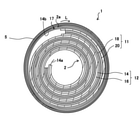
- FIG. 2 is a cross-sectional view of a non-aqueous electrolyte secondary battery along the line L1-L1 in FIG.
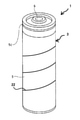
- FIG. 3 is a schematic perspective view of a secondary battery showing a welded portion between a laminated portion including an exposed portion of a negative electrode current collector and a case body.
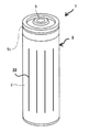
- FIG. 4 is a schematic perspective view of a secondary battery showing a welded portion between a laminated portion including an exposed portion of a negative electrode current collector and a case body.
- FIG. 5 is a schematic perspective view of a secondary battery showing a welded portion between a laminated portion including an exposed portion of a negative electrode current collector and a case body.
- FIG. 6 is a schematic perspective view of a secondary battery showing a welded portion between a laminated portion including an exposed portion of a negative electrode current collector and a case body.
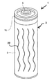
- FIG. 7 is a schematic perspective view of a secondary battery showing a welded portion between a laminated portion including an exposed portion of a negative electrode current collector and a case body.
- FIG. 8 is a schematic perspective view of a secondary battery showing a welded portion between a laminated portion including an exposed portion of a negative electrode current collector and a case body.
- the secondary battery is a power storage device that can be repeatedly charged and discharged, and examples thereof include a non-aqueous electrolyte secondary battery such as a lithium ion secondary battery, an aqueous secondary battery such as an alkaline secondary battery, and the like. Be done.
- a non-aqueous electrolyte secondary battery such as a lithium ion secondary battery
- an aqueous secondary battery such as an alkaline secondary battery, and the like.
- FIG. 1 is a perspective view showing the appearance of the non-aqueous electrolyte secondary battery according to the embodiment.
- FIG. 2 is a cross-sectional view of a non-aqueous electrolyte secondary battery along the line L1-L1 in FIG.
- the non-aqueous electrolyte secondary battery 1 includes an electrode body 2, a non-aqueous electrolyte (not shown), and a battery case 3.
- the battery case 3 includes a metal case body 5 having an opening and a sealing body 6 for sealing the opening of the case body 5.
- the electrode body 2, a non-aqueous electrolyte, and the like are housed in the case body 5.
- the case body 5 is, for example, a bottomed cylindrical metal outer can, and a groove portion 5c protruding inward along the circumferential direction is formed on the upper portion of the case body 5.
- the sealing body 6 is supported by the groove portion 5c and seals the opening of the case body 5. In order to ensure the airtightness inside the battery, it is desirable to provide a gasket between the case body 5 and the sealing body 6.
- the electrode body 2 shown in FIG. 2 is a winding type electrode body in which the positive electrode 11 and the negative electrode 12 are wound via a separator. However, in FIG. 2, the separator arranged between the positive electrode 11 and the negative electrode 12 is not shown.
- the electrode body 2 shown in FIG. 2 has a cylindrical shape, but the shape of the electrode body 2 is not limited to this, and may be a flat shape or the like.
- the negative electrode 12 includes a negative electrode current collector 14 and a negative electrode active material layer 16 formed on the negative electrode current collector 14. It is desirable that the negative electrode active material layer 16 is formed on both surfaces of the negative electrode current collector 14.
- the negative electrode 12 has the negative electrode current collector exposed portions 14a and 14b in which the negative electrode active material layer 16 is not arranged on the negative electrode current collector 14 and the negative electrode current collector 14 is exposed.
- the negative electrode current collector exposed portion 14a is located at the winding start end of the negative electrode 12, and the negative electrode current collector exposed portion 14b is located at the winding end of the negative electrode 12.
- the negative electrode current collector exposed portion 14b forms the outermost outer peripheral surface of the electrode body 2, and by rotating from the winding end end portion 2a of the electrode body 2 in the winding start direction (arrow L direction) more than one turn.
- a laminated portion 17 composed of a negative electrode current collector exposed portion 14b is formed.
- a part of the negative electrode current collector exposed portion 14b forming the laminated portion 17 may be folded back from the winding end end of the electrode body 2 in the direction opposite to the winding direction.
- the laminated portion 17 has a structure in which the negative electrode current collector exposed portion 14b is laminated in the radial direction from the outermost peripheral surface of the electrode body 2. Then, the laminated portion 17 composed of the negative electrode current collector exposed portion 14b and the case main body 5 are welded to each other. For welding between the laminated portion 17 and the case body 5, for example, after the electrode body 2 is housed in the case main body 5, a laser is irradiated from the outside of the case main body 5 with the laminated portion 17 in contact with the inner surface of the case main body 5.
- the type of welding is not particularly limited as long as the laminated portion 17 and the case body 5 can be welded, and examples thereof include laser welding and electron beam welding.
- Laser welding is preferable in terms of workability, welding strength, and the like, and a semiconductor laser or a fiber laser is preferably used for laser welding.
- a tape for fixing the winding end end 2a can be attached to the outermost peripheral surface of the electrode body 2 as long as the welding of the laminated portion 17 and the case body 5 is not hindered.
- the negative electrode current collector exposed portion 14b is in contact with the case main body 5 as compared with the case where the negative electrode current collector exposed portion 14b is simply in contact with the case main body 5. Therefore, it is possible to maintain a good energization state between the negative electrode current collector exposed portion 14b and the case body 5. For example, it is possible to suppress fluctuations in the contact state between the negative electrode current collector exposed portion 14b and the case body 5 due to the charging state of the electrode body 2 and deterioration due to use and aging, and to suppress the fluctuation of the contact state between the negative electrode current collector exposed portion 14b and the case body 5. It is possible to maintain a good energized state.
- the laminated portion 17 composed of the negative electrode current collector exposed portion 14b and the case main body 5 may be welded to each other to achieve the following effects.
- (1) it is possible to secure a good energized state without using a negative electrode tab attached to the negative electrode, and this enables a uniform layout of the electrode body and local stress on the electrode. , Performance degradation, electrode buckling, etc. are less likely to occur.
- (2) For example, since the electrode body is fixed to the case body, the insulators arranged above and below the electrode body are not required, and the displacement applied to the connection portion of the electrode tab is reduced, so that the vibration resistance is improved. ..
- the negative electrode current collector exposed portion 14b forms the outermost outer peripheral surface of the electrode body 2, and preferably goes around two or more turns in the winding start direction (arrow L direction) from the winding end end portion 2a of the electrode body 2. It is more preferable to make 5 or more laps, and it is more preferable to make 10 or more laps.
- the laminated portion 17 composed of the negative electrode current collector exposed portion 14b can be formed over the entire side surface of the electrode body 2, and the thickness of the laminated portion 17 can be increased. By forming the laminated portion 17 over the entire side surface of the electrode body 2, the weldable range is expanded, and the welding work becomes easy.
- the thickness of the laminated portion 17 is, for example, preferably 20 ⁇ m or more and 200 ⁇ m or less, and more preferably 40 ⁇ m or more and 200 ⁇ m or less, in terms of suppressing the occurrence of damage to the laminated portion 17 during welding.
- FIGS. 3 and 6 are schematic perspective views of a secondary battery showing a welded portion between a laminated portion including an exposed portion of a negative electrode current collector and a case body.
- the laser is continuously irradiated over the entire outer peripheral surface of the case main body 5, and the welded portion 22 between the laminated portion 17 and the case main body 5 is welded.
- the case body 5 is continuously formed over the entire side surface of the case body 5.
- the shape of the welded portion 22 continuously formed over the entire circumference of the side surface of the case body 5 for example, the annular shape as shown in FIGS. 3 and 6 (in addition, in FIG. 6, the annular shaped welded portion 22 is formed.
- the welded portion 22 between the laminated portion 17 and the case body 5 is formed on the entire side surface of the case body 5. They may be formed at predetermined intervals. Examples of the shape of the welded portion 22 include a linear shape as shown in FIG. 5, a wavy line shape as shown in FIG. 7, a sawtooth shape as shown in FIG. 8, and the like.
- the negative electrode tab can be omitted, but the negative electrode tab may be used.
- the negative electrode tab for example, it is desirable to connect one end of the negative electrode tab to the exposed negative electrode collector 14a and connect the other end of the negative electrode tab to the bottom of the case body 5.
- the negative electrode current collector 14 for example, a metal foil stable in the potential range of the negative electrode 12 such as copper is used.
- the thickness of the negative electrode current collector 14 is preferably, for example, 4 ⁇ m or more and 40 ⁇ m or less, and more preferably 8 ⁇ m or more and 40 ⁇ m or less, in terms of suppressing the occurrence of damage to the laminated portion 17 during welding. preferable.
- the laminated portion 17 composed of the negative electrode current collector exposed portion 14b has been described, but the laminated portion 17 has another metal foil on the negative electrode current collector exposed portion 14b. It can also be attached and formed. That is, the metal foil constituting the laminated portion 17 is not limited to the negative electrode current collector 14. It is preferable that the negative electrode current collector exposed portion 14b and the other metal foil are welded to each other. Further, it is preferable that the laminated portion 17 is arranged on the entire circumference of the outermost periphery of the electrode body 2.
- the negative electrode active material layer 16 contains, for example, a negative electrode active material, a binder, and the like.
- the negative electrode active material is not particularly limited as long as it is a material capable of occluding and releasing lithium ions.
- a metal alloying with Li such as Si and Sn, a metal compound containing Si and Sn, a lithium titanium composite oxide and the like may be used.
- the negative electrode active material contains, for example, a carbon material and a Si material, and the ratio of the Si material to the total mass of the negative electrode active material is preferably 5.5% by mass or more.
- the Si material include SiO x (0.5 ⁇ x ⁇ 1.6).
- binder examples include fluororesin, PAN, polyimide resin, acrylic resin, polyolefin resin, styrene-butadiene rubber (SBR), nitrile-butadiene rubber (NBR), carboxymethyl cellulose (CMC) or a salt thereof.
- SBR styrene-butadiene rubber
- NBR nitrile-butadiene rubber
- CMC carboxymethyl cellulose
- PAA Polyacrylic acid
- PAA-Na, PAA-K or the like, or a partially neutralized salt thereof polyvinyl alcohol (PVA) and the like. These may be used alone or in combination of two or more.
- a negative electrode mixture slurry containing a negative electrode active material, a binder, and the like is prepared, and the negative electrode mixture slurry is placed on the negative electrode current collector 14 except for a region to be an exposed portion of the negative electrode current collector. It can be produced by applying and drying to form the negative electrode active material layer 16 and rolling the negative electrode active material layer.
- the positive electrode 11 includes a positive electrode current collector 18 and a positive electrode active material layer 20 arranged on the positive electrode current collector 18. As shown in FIG. 2, it is desirable that the positive electrode active material layer 20 is arranged on both sides of the positive electrode current collector 18. Although the description in the figure is omitted, in the positive electrode 11, for example, the positive electrode active material layer 20 is not arranged on the positive electrode current collector 18, and the positive electrode current collector 18 is exposed. Have. Then, one end of the positive electrode tab is connected to the exposed portion of the positive electrode current collector, and the other end is connected to the inner wall of the sealing body 6. As a result, the sealing body 6 becomes the positive electrode 11 terminal.
- a metal foil stable in the potential range of the positive electrode 11 such as aluminum, a film on which the metal is arranged on the surface layer, or the like can be used.
- the positive electrode active material layer 20 contains, for example, a positive electrode active material, a binder, a conductive material, and the like.
- Examples of the positive electrode active material include lithium transition metal oxides containing transition metal elements such as Co, Mn, and Ni.
- Lithium transition metal oxides include, for example, Li x CoO 2 , Li x NiO 2 , Li x MnO 2 , Li x Coy Ni 1-y O 2 , Li x Coy M 1-y Oz , Li x Ni 1- y My O z , Li x Mn 2 O 4 , Li x Mn 2-y My O 4 , LiMPO 4 , Li 2 MPO 4 F (M; Na, Mg, Sc, Y, Mn, Fe, Co, Ni , Cu, Zn, Al, Cr, Pb, Sb, B, 0 ⁇ x ⁇ 1.2, 0 ⁇ y ⁇ 0.9, 2.0 ⁇ z ⁇ 2.3).
- the positive electrode active materials are Li x NiO 2 , Li x Coy Ni 1-y O 2 , Li x Ni 1-y My Oz (M; Na, Mg). , Sc, Y, Mn, Fe, Co, Ni, Cu, Zn, Al, Cr, Pb, Sb, B, 0 ⁇ x ⁇ 1.2, 0 ⁇ y ⁇ 0.9, 2. It is preferable to contain a lithium nickel composite oxide such as 0 ⁇ z ⁇ 2.3).
- Examples of the conductive material include carbon particles such as carbon black (CB), acetylene black (AB), Ketjen black, and graphite. These may be used alone or in combination of two or more.
- binder examples include fluororesins such as polytetrafluoroethylene (PTFE) and polyvinylidene fluoride (PVdF), polyacrylonitrile (PAN), polyimide resins, acrylic resins, and polyolefin resins. These may be used alone or in combination of two or more.
- fluororesins such as polytetrafluoroethylene (PTFE) and polyvinylidene fluoride (PVdF), polyacrylonitrile (PAN), polyimide resins, acrylic resins, and polyolefin resins. These may be used alone or in combination of two or more.
- a positive electrode mixture slurry containing a positive electrode active material, a binder, a conductive material, etc. is applied onto the positive electrode current collector 18 and dried to form a positive electrode active material layer 20, and then the positive electrode active material is formed. It can be produced by rolling the layer 20.
- a porous sheet having ion permeability and insulating property is used.
- the porous sheet include a microporous thin film, a woven fabric, and a non-woven fabric.
- an olefin resin such as polyethylene and polypropylene, cellulose and the like are suitable.
- the separator may be a laminate having a cellulose fiber layer and a thermoplastic resin fiber layer such as an olefin resin.
- a multilayer separator including a polyethylene layer and a polypropylene layer may be used, or a separator having a surface coated with a material such as an aramid resin or ceramic may be used.
- the non-aqueous electrolyte includes, for example, an electrolyte salt and a non-aqueous solvent that dissolves the electrolyte salt.
- the electrolyte salt is preferably a lithium salt.
- lithium salts include LiBF 4 , LiClO 4 , LiPF 6 , LiAsF 6 , LiSbF 6 , LiAlCl 4 , LiSCN, LiCF 3 SO 3 , LiCF 3 CO 2 , Li (P (C 2 O 4 ) F 4 ), LiPF 6-x (C n F 2n + 1 ) x (1 ⁇ x ⁇ 6, n is 1 or 2 ), LiB 10 Cl 10 , LiCl, LiBr, LiI, chloroborane lithium, lower aliphatic carboxylate lithium, Li 2B 4 O 7 , borates such as Li (B (C 2 O 4 ) F 2 ), LiN (SO 2 CF 3 ) 2 , LiN (C1F 2l + 1 SO 2 )
- lithium salt these may be used alone or in combination of two or more.
- LiPF 6 is preferably used from the viewpoint of ionic conductivity, electrochemical stability, and the like.
- concentration of the lithium salt is preferably 0.8 to 1.8 mol per 1 L of the non-aqueous solvent.
- non-aqueous solvent for example, esters, ethers, nitriles such as acetonitrile, amides such as dimethylformamide, and a mixed solvent of two or more of these can be used.
- the non-aqueous solvent may contain a halogen-substituted product in which at least a part of hydrogen in these solvents is substituted with a halogen atom such as fluorine.
- esters examples include cyclic carbonate esters such as ethylene carbonate (EC), propylene carbonate (PC) and butylene carbonate, dimethyl carbonate (DMC), ethyl methyl carbonate (EMC), diethyl carbonate (DEC) and methylpropyl carbonate.
- Ethylpropyl carbonate chain carbonate ester such as methylisopropylcarbonate
- cyclic carboxylic acid ester such as ⁇ -butyrolactone, ⁇ -valerolactone, methyl acetate, ethyl acetate, propyl acetate, methyl propionate (MP), ethyl propionate, etc.
- chain carboxylic acid ester of examples include the chain carboxylic acid ester of.
- ethers examples include 1,3-dioxolane, 4-methyl-1,3-dioxolane, tetrahydrofuran, 2-methyltetrahexyl, propylene oxide, 1,2-butylene oxide, 1,3-dioxane, 1,4.
- -Cyclic ethers such as dioxane, 1,3,5-trioxane, furan, 2-methylfuran, 1,8-cineole, crown ether, 1,2-dimethoxyethane, diethyl ether, dipropyl ether, diisopropyl ether, dibutyl ether , Dihexyl ether, ethyl vinyl ether, butyl vinyl ether, methyl phenyl ether, ethyl phenyl ether, butyl phenyl ether, pentyl phenyl ether, methoxy toluene, benzyl ethyl ether, diphenyl ether, dibenzyl ether, o-dimethoxybenzene, 1,2-diethoxy Chain ethers such as ethane, 1,2-dibutoxyethane, diethylene glycol dimethyl ether, diethylene glycol diethyl ether, diethylene glycol dibutyl
- a fluorinated cyclic carbonate ester such as fluoroethylene carbonate (FEC), a fluorinated chain carbonate ester, a fluorinated chain carboxylic acid ester such as methyl fluoropropionate (FMP), or the like. ..
- Non-aqueous electrolyte secondary battery 2 Electrode body, 2a Winding end end, 3 Battery case, 5 Case body, 5c groove, 6 Seal body, 11 Positive electrode, 12 Negative electrode, 14 Negative electrode current collector, 14a, 14b Negative electrode collection Exposed part of electric body, 16 negative electrode active material layer, 17 laminated part, 18 positive electrode current collector, 20 positive electrode active material layer, 22 welded part.
Landscapes
- Chemical & Material Sciences (AREA)
- Chemical Kinetics & Catalysis (AREA)
- General Chemical & Material Sciences (AREA)
- Electrochemistry (AREA)
- Engineering & Computer Science (AREA)
- Manufacturing & Machinery (AREA)
- Inorganic Chemistry (AREA)
- Physics & Mathematics (AREA)
- Optics & Photonics (AREA)
- Materials Engineering (AREA)
- Mechanical Engineering (AREA)
- Plasma & Fusion (AREA)
- Secondary Cells (AREA)
Abstract
Description
Claims (6)
- 開口部を有する金属製のケース本体と、
前記ケース本体の前記開口部を封口する封口体と、
前記ケース本体に収容された、正極と負極とをセパレータを介して巻回した電極体と、を有する二次電池であって、
前記負極は、負極集電体と、負極集電体上に形成された負極活物質層と、前記負極活物質層が形成されておらず、前記負極集電体が露出した露出部と、を有し、
前記露出部は前記負極の巻き終わり端部に配置され、
前記電極体は、前記露出部を含む金属箔が積層した積層部を有し、
前記積層部と前記ケース本体とが溶接されている、二次電池。 - 前記積層部は、前記電極体の最外周の全周に配置されている、請求項1に記載の二次電池。
- 前記積層部は、前記電極体の巻き終わり端部から巻き始め方向に1周を超えて周回した前記露出部からなる、請求項1に記載の二次電池。
- 前記露出部は前記電極体の巻き終わり端部から巻き始め方向に2周以上周回している、請求項3に記載の二次電池。
- 前記積層部と前記ケース本体とは、前記ケース本体の側面全周に亘って連続して溶接されている、請求項2又は4に記載の二次電池。
- 前記積層部の厚みは、20μm以上200μm以下である、請求項1~5のいずれか1項に記載の二次電池。
Priority Applications (4)
| Application Number | Priority Date | Filing Date | Title |
|---|---|---|---|
| CN202180050511.2A CN115956313A (zh) | 2020-08-28 | 2021-08-19 | 二次电池 |
| EP21861364.4A EP4207405A4 (en) | 2020-08-28 | 2021-08-19 | Secondary battery |
| US18/021,997 US20240006726A1 (en) | 2020-08-28 | 2021-08-19 | Secondary battery |
| JP2022544507A JP7715716B2 (ja) | 2020-08-28 | 2021-08-19 | 二次電池 |
Applications Claiming Priority (2)
| Application Number | Priority Date | Filing Date | Title |
|---|---|---|---|
| JP2020144931 | 2020-08-28 | ||
| JP2020-144931 | 2020-08-28 |
Publications (1)
| Publication Number | Publication Date |
|---|---|
| WO2022044936A1 true WO2022044936A1 (ja) | 2022-03-03 |
Family
ID=80355150
Family Applications (1)
| Application Number | Title | Priority Date | Filing Date |
|---|---|---|---|
| PCT/JP2021/030302 Ceased WO2022044936A1 (ja) | 2020-08-28 | 2021-08-19 | 二次電池 |
Country Status (5)
| Country | Link |
|---|---|
| US (1) | US20240006726A1 (ja) |
| EP (1) | EP4207405A4 (ja) |
| JP (1) | JP7715716B2 (ja) |
| CN (1) | CN115956313A (ja) |
| WO (1) | WO2022044936A1 (ja) |
Cited By (3)
| Publication number | Priority date | Publication date | Assignee | Title |
|---|---|---|---|---|
| EP4383386A1 (en) * | 2022-12-09 | 2024-06-12 | Volvo Truck Corporation | Battery cell with improved heat transfer |
| WO2025164364A1 (ja) * | 2024-01-31 | 2025-08-07 | パナソニックIpマネジメント株式会社 | 円筒形二次電池 |
| EP4525109A4 (en) * | 2022-07-19 | 2026-02-11 | Lg Energy Solution Ltd | CYLINDRICAL BATTERY, BATTERY BLOCK AND VEHICLE |
Families Citing this family (3)
| Publication number | Priority date | Publication date | Assignee | Title |
|---|---|---|---|---|
| USD899355S1 (en) * | 2016-08-15 | 2020-10-20 | Milwaukee Electric Tool Corporation | Battery |
| USD1079601S1 (en) * | 2022-07-18 | 2025-06-17 | Xiamen Hithium Energy Storage Technology Co., Ltd. | Cylindrical battery |
| USD1079600S1 (en) * | 2022-08-29 | 2025-06-17 | Xiamen Hithium Energy Storage Technology Co., Ltd. | Cylindrical battery |
Citations (6)
| Publication number | Priority date | Publication date | Assignee | Title |
|---|---|---|---|---|
| JP2000133240A (ja) * | 1998-10-30 | 2000-05-12 | Sanyo Electric Co Ltd | 溶接封口電池の電極集電タブ |
| JP2001068145A (ja) * | 1999-08-30 | 2001-03-16 | Toshiba Battery Co Ltd | 角形アルカリ二次電池 |
| JP2013254561A (ja) | 2010-09-30 | 2013-12-19 | Panasonic Corp | 円筒形非水電解質二次電池 |
| WO2017163933A1 (ja) * | 2016-03-24 | 2017-09-28 | 三洋電機株式会社 | 非水電解質二次電池 |
| WO2019004039A1 (ja) * | 2017-06-28 | 2019-01-03 | 三洋電機株式会社 | 電池及びその製造方法 |
| WO2019187775A1 (ja) * | 2018-03-28 | 2019-10-03 | 三洋電機株式会社 | 電池及びその製造方法 |
Family Cites Families (9)
| Publication number | Priority date | Publication date | Assignee | Title |
|---|---|---|---|---|
| JPH08203562A (ja) * | 1995-01-27 | 1996-08-09 | Asahi Chem Ind Co Ltd | 電 池 |
| US20100233524A1 (en) * | 2008-05-28 | 2010-09-16 | Yasuhiko Hina | Cylindrical non-aqueous electrolyte secondary battery |
| CN101640286B (zh) * | 2008-08-01 | 2011-12-07 | 上海比亚迪有限公司 | 卷绕式锂电池的电芯及卷绕式锂电池 |
| WO2016147564A1 (ja) * | 2015-03-13 | 2016-09-22 | 三洋電機株式会社 | 非水電解質二次電池 |
| CN105514480B (zh) * | 2016-02-01 | 2019-01-15 | 陈佩 | 圆柱形锂离子电池及负极端的封装方法 |
| JPWO2019098023A1 (ja) * | 2017-11-16 | 2020-11-19 | パナソニックIpマネジメント株式会社 | 円筒形二次電池 |
| CN112400250A (zh) * | 2018-06-28 | 2021-02-23 | 三洋电机株式会社 | 非水电解质二次电池 |
| WO2020084986A1 (ja) * | 2018-10-26 | 2020-04-30 | パナソニックIpマネジメント株式会社 | 円筒型二次電池 |
| CN110098429B (zh) * | 2019-03-22 | 2021-11-26 | 华为数字能源技术有限公司 | 一种电池、用电装置及电芯安装方法 |
-
2021
- 2021-08-19 US US18/021,997 patent/US20240006726A1/en active Pending
- 2021-08-19 JP JP2022544507A patent/JP7715716B2/ja active Active
- 2021-08-19 CN CN202180050511.2A patent/CN115956313A/zh active Pending
- 2021-08-19 EP EP21861364.4A patent/EP4207405A4/en active Pending
- 2021-08-19 WO PCT/JP2021/030302 patent/WO2022044936A1/ja not_active Ceased
Patent Citations (6)
| Publication number | Priority date | Publication date | Assignee | Title |
|---|---|---|---|---|
| JP2000133240A (ja) * | 1998-10-30 | 2000-05-12 | Sanyo Electric Co Ltd | 溶接封口電池の電極集電タブ |
| JP2001068145A (ja) * | 1999-08-30 | 2001-03-16 | Toshiba Battery Co Ltd | 角形アルカリ二次電池 |
| JP2013254561A (ja) | 2010-09-30 | 2013-12-19 | Panasonic Corp | 円筒形非水電解質二次電池 |
| WO2017163933A1 (ja) * | 2016-03-24 | 2017-09-28 | 三洋電機株式会社 | 非水電解質二次電池 |
| WO2019004039A1 (ja) * | 2017-06-28 | 2019-01-03 | 三洋電機株式会社 | 電池及びその製造方法 |
| WO2019187775A1 (ja) * | 2018-03-28 | 2019-10-03 | 三洋電機株式会社 | 電池及びその製造方法 |
Non-Patent Citations (1)
| Title |
|---|
| See also references of EP4207405A4 |
Cited By (3)
| Publication number | Priority date | Publication date | Assignee | Title |
|---|---|---|---|---|
| EP4525109A4 (en) * | 2022-07-19 | 2026-02-11 | Lg Energy Solution Ltd | CYLINDRICAL BATTERY, BATTERY BLOCK AND VEHICLE |
| EP4383386A1 (en) * | 2022-12-09 | 2024-06-12 | Volvo Truck Corporation | Battery cell with improved heat transfer |
| WO2025164364A1 (ja) * | 2024-01-31 | 2025-08-07 | パナソニックIpマネジメント株式会社 | 円筒形二次電池 |
Also Published As
| Publication number | Publication date |
|---|---|
| JP7715716B2 (ja) | 2025-07-30 |
| CN115956313A (zh) | 2023-04-11 |
| EP4207405A4 (en) | 2024-11-13 |
| US20240006726A1 (en) | 2024-01-04 |
| JPWO2022044936A1 (ja) | 2022-03-03 |
| EP4207405A1 (en) | 2023-07-05 |
Similar Documents
| Publication | Publication Date | Title |
|---|---|---|
| JP6948601B2 (ja) | 二次電池 | |
| JP7320738B2 (ja) | 円筒型二次電池 | |
| WO2022044936A1 (ja) | 二次電池 | |
| JP7194940B2 (ja) | リチウム二次電池 | |
| US20210043979A1 (en) | Non-aqueous electrolyte secondary battery | |
| JP7212629B2 (ja) | リチウムイオン二次電池 | |
| US20240021882A1 (en) | Cylindrical secondary battery having high structural safety and method of manufacturing the same | |
| EP3780211B1 (en) | Secondary battery, battery module, vehicle and flying object | |
| JPWO2020066108A1 (ja) | セパレータおよび非水電解質二次電池 | |
| JP7361339B2 (ja) | 非水電解質二次電池用負極及び非水電解質二次電池 | |
| US20240258555A1 (en) | Non-aqueous electrolyte secondary battery | |
| JPWO2020110589A1 (ja) | 非水電解質二次電池用負極及び非水電解質二次電池 | |
| JP2018190624A (ja) | 非水電解質二次電池 | |
| WO2020110691A1 (ja) | 非水電解質二次電池用負極及び非水電解質二次電池 | |
| WO2019069356A1 (ja) | 電極群、二次電池、電池モジュール、蓄電装置、車両及び飛翔体 | |
| KR101791432B1 (ko) | 집전체의 일부로 이루어진 전극단자를 포함하는 전극조립체 | |
| US11811053B2 (en) | Positive electrode and secondary battery | |
| WO2022024703A1 (ja) | 非水電解液二次電池及び非水電解液二次電池の製造方法 | |
| JP7837950B2 (ja) | 非水電解液二次電池及び非水電解液二次電池の製造方法 | |
| CN223181352U (zh) | 二次电池 | |
| US20240291015A1 (en) | Non-aqueous electrolyte secondary battery | |
| WO2022113836A1 (ja) | 非水電解質二次電池 | |
| WO2026071131A1 (ja) | 非水電解質二次電池 | |
| WO2022113796A1 (ja) | 非水電解質二次電池用正極及び非水電解質二次電池 | |
| WO2022113797A1 (ja) | 非水電解質二次電池 |
Legal Events
| Date | Code | Title | Description |
|---|---|---|---|
| 121 | Ep: the epo has been informed by wipo that ep was designated in this application |
Ref document number: 21861364 Country of ref document: EP Kind code of ref document: A1 |
|
| ENP | Entry into the national phase |
Ref document number: 2022544507 Country of ref document: JP Kind code of ref document: A |
|
| WWE | Wipo information: entry into national phase |
Ref document number: 202317010556 Country of ref document: IN |
|
| WWE | Wipo information: entry into national phase |
Ref document number: 18021997 Country of ref document: US |
|
| NENP | Non-entry into the national phase |
Ref country code: DE |
|
| ENP | Entry into the national phase |
Ref document number: 2021861364 Country of ref document: EP Effective date: 20230328 |
|
| WWG | Wipo information: grant in national office |
Ref document number: 202317010556 Country of ref document: IN |