WO2022049631A1 - 術具 - Google Patents
術具 Download PDFInfo
- Publication number
- WO2022049631A1 WO2022049631A1 PCT/JP2020/033087 JP2020033087W WO2022049631A1 WO 2022049631 A1 WO2022049631 A1 WO 2022049631A1 JP 2020033087 W JP2020033087 W JP 2020033087W WO 2022049631 A1 WO2022049631 A1 WO 2022049631A1
- Authority
- WO
- WIPO (PCT)
- Prior art keywords
- slider
- conversion
- movement amount
- surgical tool
- treatment
- Prior art date
- Legal status (The legal status is an assumption and is not a legal conclusion. Google has not performed a legal analysis and makes no representation as to the accuracy of the status listed.)
- Ceased
Links
Images


Classifications
-
- A—HUMAN NECESSITIES
- A61—MEDICAL OR VETERINARY SCIENCE; HYGIENE
- A61B—DIAGNOSIS; SURGERY; IDENTIFICATION
- A61B34/00—Computer-aided surgery; Manipulators or robots specially adapted for use in surgery
- A61B34/70—Manipulators specially adapted for use in surgery
- A61B34/71—Manipulators operated by drive cable mechanisms
-
- A—HUMAN NECESSITIES
- A61—MEDICAL OR VETERINARY SCIENCE; HYGIENE
- A61B—DIAGNOSIS; SURGERY; IDENTIFICATION
- A61B17/00—Surgical instruments, devices or methods
- A61B17/00234—Surgical instruments, devices or methods for minimally invasive surgery
-
- A—HUMAN NECESSITIES
- A61—MEDICAL OR VETERINARY SCIENCE; HYGIENE
- A61B—DIAGNOSIS; SURGERY; IDENTIFICATION
- A61B34/00—Computer-aided surgery; Manipulators or robots specially adapted for use in surgery
- A61B34/30—Surgical robots
-
- A—HUMAN NECESSITIES
- A61—MEDICAL OR VETERINARY SCIENCE; HYGIENE
- A61B—DIAGNOSIS; SURGERY; IDENTIFICATION
- A61B17/00—Surgical instruments, devices or methods
- A61B17/00234—Surgical instruments, devices or methods for minimally invasive surgery
- A61B2017/00292—Surgical instruments, devices or methods for minimally invasive surgery mounted on or guided by flexible, e.g. catheter-like, means
- A61B2017/00296—Surgical instruments, devices or methods for minimally invasive surgery mounted on or guided by flexible, e.g. catheter-like, means mounted on an endoscope
-
- A—HUMAN NECESSITIES
- A61—MEDICAL OR VETERINARY SCIENCE; HYGIENE
- A61B—DIAGNOSIS; SURGERY; IDENTIFICATION
- A61B17/00—Surgical instruments, devices or methods
- A61B17/00234—Surgical instruments, devices or methods for minimally invasive surgery
- A61B2017/00292—Surgical instruments, devices or methods for minimally invasive surgery mounted on or guided by flexible, e.g. catheter-like, means
- A61B2017/003—Steerable
- A61B2017/00318—Steering mechanisms
- A61B2017/00323—Cables or rods
-
- A—HUMAN NECESSITIES
- A61—MEDICAL OR VETERINARY SCIENCE; HYGIENE
- A61B—DIAGNOSIS; SURGERY; IDENTIFICATION
- A61B34/00—Computer-aided surgery; Manipulators or robots specially adapted for use in surgery
- A61B34/30—Surgical robots
- A61B2034/301—Surgical robots for introducing or steering flexible instruments inserted into the body, e.g. catheters or endoscopes
Definitions
- This disclosure relates to surgical tools.
- the slider of the operation unit moves linearly, and the linear movement of the slider is transmitted to the treatment unit by a wire or the like, so that the treatment unit operates by the amount of movement that the slider is operated.
- One aspect of the present disclosure is to provide a technique for improving operability in a surgical tool provided with an operation unit having a slider that moves linearly.
- One aspect of the present disclosure is a surgical tool, which includes a slider, a conversion unit, and a transmission wire.
- the slider is arranged so as to be relatively movable in a linear direction with respect to a main body provided with at least a treatment unit for performing a medical procedure.
- the conversion unit moves by the conversion movement amount obtained by converting the movement amount of the slider to a predetermined magnification.
- the transmission wire transmits the conversion transfer amount to the treatment unit.
- the amount of movement of the slider that moves linearly is converted to a predetermined magnification in the conversion unit. Therefore, only the amount of conversion movement converted to a predetermined magnification in the conversion unit is transmitted to the treatment unit. Therefore, for example, by reducing the predetermined magnification, the conversion movement amount becomes smaller than the movement amount of the slider.
- the treatment unit operates according to the conversion movement amount, it becomes easy to perform detailed work. That is, the operability can be improved in a surgical tool provided with an operation unit having a slider that moves linearly.
- the conversion unit may include a conversion wire and a moving pulley.
- the conversion wire has a first end attached to the slider and a second end attached to the body.
- the conversion wire is arranged on the peripheral surface.
- the conversion movement amount obtained by converting the movement amount of the slider to a predetermined magnification is transmitted to the treatment unit by the conversion units provided on one side and the other side with respect to the movement direction of the slider. Can be done.
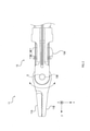
- the surgical tool 1 in the present embodiment is a medical device used for medical practice such as surgery.
- the surgical tool 1 includes a treatment unit 10 and a main body 20.
- the treatment unit 10 is a part of the surgical instrument 1 used for medical treatment.
- the treatment portion 10 is formed in an elongated shape, for example, and the elongated first end portion is connected to the main body 20.
- the treatment unit 10 has a movable unit 11 at least in part.
- the movable portion 11 is arranged at the tip portion of the treatment portion 10, that is, at the second end portion opposite to the first end portion where the treatment portion 10 and the main body 20 are connected.
- the position where the movable portion 11 is arranged is not limited to the end portion of the treatment portion 10 on the side opposite to the end portion connected to the main body 20, but is arranged at a position other than the end portion of the treatment portion 10. May be good.
- the movable portion 11 is configured such that the tip portion is branched into two and the opening / closing operation of the branch can be performed, and the tip portions of the tip portions are respectively orthogonal to each other in two directions. It is configured so that the orientation can be adjusted. That is, the movable portion 11 is a portion that can be displaced with respect to the treatment portion 10.
- the movable portion 11 may be a portion used as, for example, a forceps. That is, the movable portion 11 may be a portion used in the treatment portion 10 as a gripping portion capable of gripping a treatment target portion, a suture needle, or the like.
- the branch opening / closing operation of the movable portion 11 may be performed by transmitting a driving force to the branched structure. Further, in the operation of adjusting the direction of the tip portion, the joint portion 13 that rotates in the direction of adjusting the direction of the tip portion is arranged, and the joint portion 13 rotates to move the movable portion 11 in the tip direction direction. It may be formed in a structure whose orientation can be adjusted.
- the joint portion 13 of the movable portion 11 has a first rotation axis 13A along the left-right direction (x-axis direction described later), and a second rotation axis 13B along the vertical direction (z-axis direction described later). May have.
- the joint portion 13 can be rotationally displaced with the rotation shafts 13A and 13B as the central axes.
- the first rotation axis 13A is an axis portion orthogonal to the longitudinal direction of the treatment portion 10.
- the second rotation axis 13B is an axis portion orthogonal to the longitudinal direction of the treatment portion 10 and the first rotation axis 13A.
- Parts and the like necessary for the treatment unit 10 to operate are arranged on the main body 20.
- the vertical direction of the main body 20 is the z-axis direction
- the upward direction is also referred to as the z-axis positive direction
- the downward direction is also referred to as the z-axis negative direction.
- the long side direction of the rectangular shape of the opening of the main body 20, that is, the longitudinal direction of the treatment portion 10 connected to the main body 20 is the y-axis direction
- the direction in which the treatment portion 10 is located when viewed from the main body 20 is the y-axis positive direction.
- the opposite direction is also referred to as the y-axis negative direction.
- the axis orthogonal to the yz plane is defined as the x-axis
- the positive direction of the z-axis is the upward direction
- the left side when facing the positive y-axis direction is the positive direction of the x-axis
- the right side is the negative direction of the x-axis.
- the x-axis direction is also referred to as the left-right direction
- the z-axis direction is also referred to as the up-down direction.
- the surface of the main body 20 viewed from the positive side of the z-axis in the negative direction of the z-axis is referred to as the front surface, and the surface of the main body 20 viewed from the negative side of the z-axis in the positive direction of the z-axis is also referred to as the back surface.
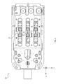
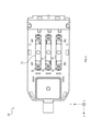
- the main body 20 has an opening 22 which is a plurality of rectangular through holes on the back surface.
- the number of rectangular openings is formed by the number of sliders 21.
- the number of sliders 21 included in the main body 20 in the present embodiment is three.
- the number of openings 22 is also three.
- the number of sliders 21 and the number of openings are not limited to three, and may be more or less than three, respectively.
- the opening 22 is arranged so that the long side direction of the rectangular shape is oriented along the longitudinal direction of the long treatment portion 10.
- the plurality of sliders 21 are arranged inside the plurality of openings 22 of the main body 20, and are arranged so as to be movable in the longitudinal direction of the openings 22. Each of the plurality of sliders 21 reciprocates to generate a driving force that displaces the movable portion 11.
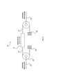
- end portion of the conversion wire 27 is fixed to each end portion of the plurality of sliders 21 in the y-axis direction.
- a plurality of moving pulleys 23 are arranged once for each conversion wire 27.
- the moving pulley 23 is arranged so that one conversion wire 27 is attached to the peripheral surface thereof.
- One slider 21 is arranged so as to be located between the two moving pulleys 23. Further, the moving pulley 23 is arranged so that the rotation axis extends in the vertical direction, in other words, in the z-axis direction.
- the first end of the transmission wire 25 is attached to the rotation shaft of the moving pulley 23 on the side closer to the treatment portion 10. Further, the second end portion, which is an end portion different from the first end portion of the transmission wire 25, is attached to the rotation shaft of the moving pulley 23 on the side opposite to the treatment portion 10.
- the transmission wire 25 extends from the moving pulley 23 on the side closer to the treatment portion 10 toward the treatment portion 10 and the movable portion 11.
- the transmission wire 25 is folded back at the treatment portion 10 and the movable portion 11.
- the transmission wire 25 folded back in the treatment portion 10 and the movable portion 11 is folded back along the fixed pulley 24 fixed to the main body 20.
- the plurality of transmission wires 25 are directly or indirectly connected to the sandwiched portion 11A and the sandwiched portion 11B branched into two and the joint portion 13.
- the plurality of transmission wires 25 are not limited to those that are directly or indirectly connected to the sandwiched portion 11A and the sandwiched portion 11B and the joint portion 13 that are branched into two, and operate on the movable portion 11. It suffices as long as it transmits the driving force for the purpose.
- the transmission wire 25 connected to any of the plurality of sliders 21 is connected to the sandwiching structure, and the transmission wire 25 connected to any of the plurality of sliders 21 is movable so as to adjust the direction of the movable portion 11. It may be arranged on the peripheral surface of the rotating portion of the joint portion 13 included in the portion 11.
- the moving pulley 23 and the conversion wire 27 in the present embodiment correspond to an example of the configuration as the conversion unit.
- Each of the plurality of sliders 21 makes a linear motion along the longitudinal direction of the rectangular shape inside the plurality of openings 22 by the operation of the operator.
- the driving force applied to the transmission wire 25 and the amount of conversion movement due to the linear motion of the slider 21 are transmitted to the movable portion 11.
- the movable portion 11 operates according to the conversion movement amount and the driving force of the transmitted transmission wire 25.
- the operation according to the conversion movement amount and the driving force of the transmitted transmission wire 25 of the movable portion 11 is, for example, the pinching operation by the pinching portion 11A and the pinching portion 11B, the pinching release operation, and the joint portion 13. It is a rotation operation of. That is, the transmission wire 25 that directly or indirectly transmits the driving force and the conversion movement amount to the pinching portion 11A and the pinching portion 11B operates, and the pinching portion 11A and the pinching portion 11B approach or separate from each other with the central axis O as the center. As a result, the pinching operation or the pinching release operation may be performed. As a result, the movable portion 11 may be configured to open the sandwiching structure of the tip portion by the amount of conversion movement.
- the transmission wire 25 that directly or indirectly transmits the driving force and the conversion movement amount to the joint portion 13
- the operation of the rotational displacement of the joint portion 13 centered on the rotary shaft 13A and the rotary shaft 13B is performed. It may be done.
- the movable portion 11 may be configured so that the orientation of the tip portion is adjusted by the amount of conversion movement.
- the movable portion 11 of the treatment unit 10 operates according to the conversion movement amount, it becomes easy to perform detailed work. That is, the operability can be improved in the surgical tool 1 provided with the operation unit having the slider 21 that moves linearly.
- the number of the moving pulleys 23 moving with respect to the slider 21 is limited to two. It's not a thing.
- the number of moving pulleys 23 moving with respect to the slider 21 may be more or less than two.
- two sandwiching portions that sandwich each of the yz plane and the xy plane are arranged, and the transmission wire 25 to which the driving force is transmitted is connected to each of the two, whereby the pinching operation and the pinching operation can be performed. It may be arranged so that the direction in which the release is performed is different.
- the pinching operation may be performed by operating one of the sliders 21 corresponding to each of the plurality of transmission wires 25, and the tip rotation operation may be performed by operating any one of the sliders 21.
- a plurality of functions possessed by one component in the above embodiment may be realized by a plurality of components, or one function possessed by one component may be realized by a plurality of components. .. Further, a plurality of functions possessed by the plurality of components may be realized by one component, or one function realized by the plurality of components may be realized by one component. Further, a part of the configuration of the above embodiment may be omitted. Further, at least a part of the configuration of the above embodiment may be added or replaced with the configuration of the other above embodiment.
Landscapes
- Health & Medical Sciences (AREA)
- Surgery (AREA)
- Life Sciences & Earth Sciences (AREA)
- Engineering & Computer Science (AREA)
- Molecular Biology (AREA)
- Biomedical Technology (AREA)
- Heart & Thoracic Surgery (AREA)
- Medical Informatics (AREA)
- Nuclear Medicine, Radiotherapy & Molecular Imaging (AREA)
- Animal Behavior & Ethology (AREA)
- General Health & Medical Sciences (AREA)
- Public Health (AREA)
- Veterinary Medicine (AREA)
- Robotics (AREA)
- Surgical Instruments (AREA)
- Manipulator (AREA)
Abstract
Description
本実施形態における術具1は、手術などの医療行為に用いられる医療機器である。
複数のスライダ21と複数の動滑車23と複数の伝達ワイヤ25との動き、及びそれらの動きに可動部11の動くについて説明する。
(1)本実施形態では、動滑車23と変換ワイヤ27とにより、スライダ21の直線運動の移動量が、変換移動量に変換され、当該変換移動量だけ伝達ワイヤ25が移動する。当該伝達ワイヤ25の移動量が可動部11に伝達され、可動部11は25の移動量に応じて動作する。
(1)上記実施形態では、スライダ21の数は複数であるが、スライダ21の数は複数に限定されるものではなく、1つであってもよい。
Claims (3)
- 医療処置を行う処置部が少なくとも設けられた本体に対して直線方向に相対移動可能に配置されたスライダと、
前記スライダの移動量を所定の倍率に変換した変換移動量で移動する変換部と、
前記変換移動量を前記処置部に伝達する伝達ワイヤと、
を備える、術具。 - 請求項1に記載の術具であって、
前記変換部は、第1の端部が前記スライダに取り付けられ、第2の端部が前記本体に取り付けられた変換ワイヤと、
前記変換ワイヤが周面に配置された動滑車と、
を備える、術具。 - 請求項1又は請求項2に記載の術具であって、
前記変換部は、前記スライダの移動方向に対して一方側及び他方側に設けられた、術具。
Priority Applications (5)
| Application Number | Priority Date | Filing Date | Title |
|---|---|---|---|
| CN202080103643.2A CN116113382B (zh) | 2020-09-01 | 2020-09-01 | 手术工具 |
| JP2021539529A JP6991637B1 (ja) | 2020-09-01 | 2020-09-01 | 術具 |
| PCT/JP2020/033087 WO2022049631A1 (ja) | 2020-09-01 | 2020-09-01 | 術具 |
| EP20952371.1A EP4193955B1 (en) | 2020-09-01 | 2020-09-01 | Surgical tool |
| US18/176,045 US20230210509A1 (en) | 2020-09-01 | 2023-02-28 | Surgical tool |
Applications Claiming Priority (1)
| Application Number | Priority Date | Filing Date | Title |
|---|---|---|---|
| PCT/JP2020/033087 WO2022049631A1 (ja) | 2020-09-01 | 2020-09-01 | 術具 |
Related Child Applications (1)
| Application Number | Title | Priority Date | Filing Date |
|---|---|---|---|
| US18/176,045 Continuation US20230210509A1 (en) | 2020-09-01 | 2023-02-28 | Surgical tool |
Publications (1)
| Publication Number | Publication Date |
|---|---|
| WO2022049631A1 true WO2022049631A1 (ja) | 2022-03-10 |
Family
ID=80213729
Family Applications (1)
| Application Number | Title | Priority Date | Filing Date |
|---|---|---|---|
| PCT/JP2020/033087 Ceased WO2022049631A1 (ja) | 2020-09-01 | 2020-09-01 | 術具 |
Country Status (5)
| Country | Link |
|---|---|
| US (1) | US20230210509A1 (ja) |
| EP (1) | EP4193955B1 (ja) |
| JP (1) | JP6991637B1 (ja) |
| CN (1) | CN116113382B (ja) |
| WO (1) | WO2022049631A1 (ja) |
Citations (7)
| Publication number | Priority date | Publication date | Assignee | Title |
|---|---|---|---|---|
| JPH04329939A (ja) * | 1991-01-25 | 1992-11-18 | Olympus Optical Co Ltd | 内視鏡用処置具 |
| JPH11104137A (ja) * | 1997-09-30 | 1999-04-20 | Asahi Optical Co Ltd | 生検鉗子 |
| WO2017208320A1 (ja) * | 2016-05-31 | 2017-12-07 | オリンパス株式会社 | 把持機構および把持具 |
| US20190231465A1 (en) * | 2015-05-22 | 2019-08-01 | Cmr Surgical Limited | Surgical instrument driving mechanism |
| CN110353807A (zh) * | 2018-04-10 | 2019-10-22 | 苏州迈澜医疗科技有限公司 | 牵引装置和具有该牵引装置的操纵装置 |
| JP2019530530A (ja) * | 2016-10-14 | 2019-10-24 | シーエムアール・サージカル・リミテッドCmr Surgical Limited | 手術器具を関節駆動するための駆動配置 |
| WO2019244799A1 (ja) * | 2018-06-20 | 2019-12-26 | リバーフィールド株式会社 | 手術具 |
Family Cites Families (12)
| Publication number | Priority date | Publication date | Assignee | Title |
|---|---|---|---|---|
| JP2009202991A (ja) * | 2008-02-27 | 2009-09-10 | Daihatsu Motor Co Ltd | ワーク搬送装置 |
| KR101014218B1 (ko) * | 2008-07-04 | 2011-02-14 | 류재동 | 도르래 실험장치 |
| JP2011072574A (ja) * | 2009-09-30 | 2011-04-14 | Terumo Corp | 医療用マニピュレータ |
| CN105328392A (zh) * | 2015-08-14 | 2016-02-17 | 重庆圣普锣建材有限公司 | 微调焊接架 |
| GB201521808D0 (en) * | 2015-12-10 | 2016-01-27 | Cambridge Medical Robotics Ltd | Interfacing a surgical robot and instrument |
| KR101847739B1 (ko) * | 2016-10-17 | 2018-04-10 | (주)한국해사기술 | 유압시스템의 이배속 운송장치 |
| WO2018094191A1 (en) * | 2016-11-21 | 2018-05-24 | Intuitive Surgical Operations, Inc. | Cable length conserving medical instrument |
| CN208301682U (zh) * | 2017-12-20 | 2019-01-01 | 深圳市罗伯医疗科技有限公司 | 一种钢丝绳驱动的快换装置 |
| CN209835280U (zh) * | 2019-04-20 | 2019-12-24 | 杨漳山 | 一种针织机纱线张力控制装置 |
| CN110575256A (zh) * | 2019-08-28 | 2019-12-17 | 哈尔滨理工大学 | 一种孔腔内窥镜手术机器人 |
| CN111390891B (zh) * | 2019-10-24 | 2021-05-18 | 浙江工业大学 | 一种用于机器人全驱动手指气动肌肉的张紧结构 |
| CN111437036B (zh) * | 2020-03-18 | 2021-03-12 | 中国科学院深圳先进技术研究院 | 一种应用于微创手术的蛇形手术机器人 |
-
2020
- 2020-09-01 WO PCT/JP2020/033087 patent/WO2022049631A1/ja not_active Ceased
- 2020-09-01 CN CN202080103643.2A patent/CN116113382B/zh active Active
- 2020-09-01 JP JP2021539529A patent/JP6991637B1/ja active Active
- 2020-09-01 EP EP20952371.1A patent/EP4193955B1/en active Active
-
2023
- 2023-02-28 US US18/176,045 patent/US20230210509A1/en active Pending
Patent Citations (7)
| Publication number | Priority date | Publication date | Assignee | Title |
|---|---|---|---|---|
| JPH04329939A (ja) * | 1991-01-25 | 1992-11-18 | Olympus Optical Co Ltd | 内視鏡用処置具 |
| JPH11104137A (ja) * | 1997-09-30 | 1999-04-20 | Asahi Optical Co Ltd | 生検鉗子 |
| US20190231465A1 (en) * | 2015-05-22 | 2019-08-01 | Cmr Surgical Limited | Surgical instrument driving mechanism |
| WO2017208320A1 (ja) * | 2016-05-31 | 2017-12-07 | オリンパス株式会社 | 把持機構および把持具 |
| JP2019530530A (ja) * | 2016-10-14 | 2019-10-24 | シーエムアール・サージカル・リミテッドCmr Surgical Limited | 手術器具を関節駆動するための駆動配置 |
| CN110353807A (zh) * | 2018-04-10 | 2019-10-22 | 苏州迈澜医疗科技有限公司 | 牵引装置和具有该牵引装置的操纵装置 |
| WO2019244799A1 (ja) * | 2018-06-20 | 2019-12-26 | リバーフィールド株式会社 | 手術具 |
Non-Patent Citations (1)
| Title |
|---|
| See also references of EP4193955A4 |
Also Published As
| Publication number | Publication date |
|---|---|
| EP4193955A1 (en) | 2023-06-14 |
| EP4193955A4 (en) | 2023-09-27 |
| CN116113382A (zh) | 2023-05-12 |
| CN116113382B (zh) | 2025-06-10 |
| US20230210509A1 (en) | 2023-07-06 |
| EP4193955B1 (en) | 2024-12-18 |
| JP6991637B1 (ja) | 2022-01-13 |
| JPWO2022049631A1 (ja) | 2022-03-10 |
Similar Documents
| Publication | Publication Date | Title |
|---|---|---|
| US20230301730A1 (en) | Device and method for controlled motion of a tool | |
| US9027431B2 (en) | Remote centre of motion positioner | |
| US11241247B2 (en) | Snakelike surgical instrument | |
| US11592087B2 (en) | Instrument transmission converting roll to linear actuation | |
| CN109414297B (zh) | 用于机器人式的手术系统的操纵器的仪器携载装置 | |
| US11497567B2 (en) | Jointed control platform | |
| JP2021106894A (ja) | ロボット外科手術アセンブリ | |
| CN105193469A (zh) | 具有复设的闭合机构的末端执行器 | |
| JP2006289534A (ja) | マニピュレータ | |
| JP2012187311A (ja) | 医療用処置具およびマニピュレータ | |
| EP4316403B1 (en) | Rear-end transmission apparatus, medical instrument and surgical robot | |
| KR20150022414A (ko) | 복강경 수술용 로봇 | |
| JP2023528860A (ja) | 外科用ツールおよびアセンブリ | |
| CN107320183A (zh) | 一种用于微创手术机器人的手术器械及微创手术机器人 | |
| JP2025026517A (ja) | バックエンド伝動装置、医療機器および手術用ロボット | |
| JP6991637B1 (ja) | 術具 | |
| US12616532B2 (en) | Medical robot and attachment portion of medical robot | |
| JP6820636B1 (ja) | 術具 | |
| JP2018111142A (ja) | アーム装置 | |
| CN214434485U (zh) | 手术器械、执行机构及手术机器人 | |
| KR102310177B1 (ko) | 다축 방향조절이 가능한 니들 홀더 장치 | |
| JP7017286B1 (ja) | 手術器具 | |
| WO2023047517A1 (ja) | 操作装置 | |
| WO2022102073A1 (ja) | 操作装置 | |
| CN223438599U (zh) | 多关节手术器械钳头结构 |
Legal Events
| Date | Code | Title | Description |
|---|---|---|---|
| ENP | Entry into the national phase |
Ref document number: 2021539529 Country of ref document: JP Kind code of ref document: A |
|
| 121 | Ep: the epo has been informed by wipo that ep was designated in this application |
Ref document number: 20952371 Country of ref document: EP Kind code of ref document: A1 |
|
| ENP | Entry into the national phase |
Ref document number: 2020952371 Country of ref document: EP Effective date: 20230306 |
|
| NENP | Non-entry into the national phase |
Ref country code: DE |
|
| WWG | Wipo information: grant in national office |
Ref document number: 202080103643.2 Country of ref document: CN |