WO2022049678A1 - 温度制御装置 - Google Patents
温度制御装置 Download PDFInfo
- Publication number
- WO2022049678A1 WO2022049678A1 PCT/JP2020/033303 JP2020033303W WO2022049678A1 WO 2022049678 A1 WO2022049678 A1 WO 2022049678A1 JP 2020033303 W JP2020033303 W JP 2020033303W WO 2022049678 A1 WO2022049678 A1 WO 2022049678A1
- Authority
- WO
- WIPO (PCT)
- Prior art keywords
- temperature control
- control block
- hollow portion
- control device
- temperature
- Prior art date
- Legal status (The legal status is an assumption and is not a legal conclusion. Google has not performed a legal analysis and makes no representation as to the accuracy of the status listed.)
- Ceased
Links
Images





Classifications
-
- B—PERFORMING OPERATIONS; TRANSPORTING
- B01—PHYSICAL OR CHEMICAL PROCESSES OR APPARATUS IN GENERAL
- B01L—CHEMICAL OR PHYSICAL LABORATORY APPARATUS FOR GENERAL USE
- B01L7/00—Heating or cooling apparatus; Heat insulating devices
- B01L7/52—Heating or cooling apparatus; Heat insulating devices with provision for submitting samples to a predetermined sequence of different temperatures, e.g. for treating nucleic acid samples
-
- C—CHEMISTRY; METALLURGY
- C12—BIOCHEMISTRY; BEER; SPIRITS; WINE; VINEGAR; MICROBIOLOGY; ENZYMOLOGY; MUTATION OR GENETIC ENGINEERING
- C12M—APPARATUS FOR ENZYMOLOGY OR MICROBIOLOGY; APPARATUS FOR CULTURING MICROORGANISMS FOR PRODUCING BIOMASS, FOR GROWING CELLS OR FOR OBTAINING FERMENTATION OR METABOLIC PRODUCTS, i.e. BIOREACTORS OR FERMENTERS
- C12M41/00—Means for regulation, monitoring, measurement or control, e.g. flow regulation
- C12M41/12—Means for regulation, monitoring, measurement or control, e.g. flow regulation of temperature
-
- C—CHEMISTRY; METALLURGY
- C12—BIOCHEMISTRY; BEER; SPIRITS; WINE; VINEGAR; MICROBIOLOGY; ENZYMOLOGY; MUTATION OR GENETIC ENGINEERING
- C12M—APPARATUS FOR ENZYMOLOGY OR MICROBIOLOGY; APPARATUS FOR CULTURING MICROORGANISMS FOR PRODUCING BIOMASS, FOR GROWING CELLS OR FOR OBTAINING FERMENTATION OR METABOLIC PRODUCTS, i.e. BIOREACTORS OR FERMENTERS
- C12M1/00—Apparatus for enzymology or microbiology
-
- C—CHEMISTRY; METALLURGY
- C12—BIOCHEMISTRY; BEER; SPIRITS; WINE; VINEGAR; MICROBIOLOGY; ENZYMOLOGY; MUTATION OR GENETIC ENGINEERING
- C12Q—MEASURING OR TESTING PROCESSES INVOLVING ENZYMES, NUCLEIC ACIDS OR MICROORGANISMS; COMPOSITIONS OR TEST PAPERS THEREFOR; PROCESSES OF PREPARING SUCH COMPOSITIONS; CONDITION-RESPONSIVE CONTROL IN MICROBIOLOGICAL OR ENZYMOLOGICAL PROCESSES
- C12Q1/00—Measuring or testing processes involving enzymes, nucleic acids or microorganisms; Compositions therefor; Processes of preparing such compositions
- C12Q1/68—Measuring or testing processes involving enzymes, nucleic acids or microorganisms; Compositions therefor; Processes of preparing such compositions involving nucleic acids
- C12Q1/6844—Nucleic acid amplification reactions
- C12Q1/686—Polymerase chain reaction [PCR]
-
- B—PERFORMING OPERATIONS; TRANSPORTING
- B01—PHYSICAL OR CHEMICAL PROCESSES OR APPARATUS IN GENERAL
- B01L—CHEMICAL OR PHYSICAL LABORATORY APPARATUS FOR GENERAL USE
- B01L2200/00—Solutions for specific problems relating to chemical or physical laboratory apparatus
- B01L2200/02—Adapting objects or devices to another
- B01L2200/025—Align devices or objects to ensure defined positions relative to each other
-
- B—PERFORMING OPERATIONS; TRANSPORTING
- B01—PHYSICAL OR CHEMICAL PROCESSES OR APPARATUS IN GENERAL
- B01L—CHEMICAL OR PHYSICAL LABORATORY APPARATUS FOR GENERAL USE
- B01L2200/00—Solutions for specific problems relating to chemical or physical laboratory apparatus
- B01L2200/14—Process control and prevention of errors
- B01L2200/143—Quality control, feedback systems
- B01L2200/147—Employing temperature sensors
-
- B—PERFORMING OPERATIONS; TRANSPORTING
- B01—PHYSICAL OR CHEMICAL PROCESSES OR APPARATUS IN GENERAL
- B01L—CHEMICAL OR PHYSICAL LABORATORY APPARATUS FOR GENERAL USE
- B01L2300/00—Additional constructional details
- B01L2300/08—Geometry, shape and general structure
- B01L2300/0861—Configuration of multiple channels and/or chambers in a single devices
-
- B—PERFORMING OPERATIONS; TRANSPORTING
- B01—PHYSICAL OR CHEMICAL PROCESSES OR APPARATUS IN GENERAL
- B01L—CHEMICAL OR PHYSICAL LABORATORY APPARATUS FOR GENERAL USE
- B01L2300/00—Additional constructional details
- B01L2300/18—Means for temperature control
- B01L2300/1805—Conductive heating, heat from thermostatted solids is conducted to receptacles, e.g. heating plates, blocks
- B01L2300/1822—Conductive heating, heat from thermostatted solids is conducted to receptacles, e.g. heating plates, blocks using Peltier elements
Definitions
- the present invention relates to a temperature control device.
- genetic testing has come to be used not only for research purposes but also for a wide range of purposes such as personalized medicine and personalized identification, and it is desired not only to improve accuracy but also to shorten the testing time.
- a sample containing DNA (Deoxyribonucleic acid, deoxyribonucleic acid) is obtained, and then a trace amount of DNA in the sample is amplified and then analyzed to carry out a highly accurate test.
- the PCR Polymerase Chain Reaction
- a sample solution containing DNA and a solution containing a reagent for amplifying DNA are mixed, and DNA is denatured into a single strand at, for example, 94 ° C, and a complementary strand is synthesized at 60 ° C. By repeating these temperature changes, DNA can be amplified exponentially by the PCR method.
- a general temperature control device includes a temperature control element such as a Pelche element that controls a temperature change, and a temperature control block (hereinafter, also referred to as a "temperature control block") provided in contact with the temperature control element.
- the PCR method is carried out by holding the reaction vessel containing the reaction solution in a temperature control block and controlling the temperature of the temperature control block with a temperature control element.
- the thermal conductivity and heat capacity of the temperature control block affect the speeding up of the temperature change of the reaction solution in the temperature control device.
- a material having a high thermal conductivity for example, a metal such as aluminum or copper, is used for the temperature control block.
- the heat capacity is a value obtained from the specific heat, density, and volume of the material.
- thermocycle device described in Patent Document 1 includes a sample holder, a thermal reference, and a heat sink, one or more of which have a material having high thermal conductivity.
- the multiple sample support described in Patent Document 2 has a block having a single structure, a series of sample wells in the block, and a series of hollow portions in the block existing between the sample wells. The hollow portion reduces the mass of the block and the temperature change is transmitted to the sample quickly.
- the temperature control device can perform stable DNA amplification if the temperature of the temperature control block is not properly controlled and the reaction solution containing the sample and the reagent is not controlled to an appropriate temperature when performing a genetic test. However, the reliability of genetic testing is reduced. In general, even if the heat capacity is small, the temperature control block cannot uniformly transfer the heat of the temperature control element to the reaction solution if the thermal conductivity is small, and controls the reaction solution to the temperature required by the PCR method. Is difficult. On the other hand, since the temperature control block having a small size has a small internal temperature difference, it may be possible to uniformly transfer the heat of the temperature control element to the reaction solution even if the thermal conductivity is small, and the heat conduction is not necessarily large. Rate may not be required.
- the values related to the temperature change such as thermal conductivity, specific heat, and density are determined by the material used, so it is difficult to properly adjust the thermal conductivity and heat capacity. Therefore, there is a problem in changing the temperature of the reaction solution containing the sample and the reagent at high speed and with high accuracy. Therefore, the temperature control device is required to be able to change the temperature of the temperature control block at high speed and with high accuracy.
- An object of the present invention is to provide a temperature control device capable of changing the temperature of a temperature control block at high speed and with high accuracy.
- the temperature control device includes a temperature control block on which a container containing a solution can be placed, and a temperature control unit which is installed so as to be in contact with the temperature control block and changes the temperature of the solution.
- the temperature control block includes one or more hollow portions inside.
- thermocontrol device capable of changing the temperature of a temperature control block at high speed and with high accuracy.
- FIG. 6 is a cross-sectional view of the temperature control device in line AA'of FIG.
- FIG. 2 is a cross-sectional view of the temperature control device in line BB'of FIG.
- FIG. 2 is a cross-sectional view showing an outline of a temperature control device according to a second embodiment of the present invention.
- FIG. 3 is a cross-sectional view showing an outline of a temperature control device according to a third embodiment of the present invention.
- the perspective view which shows the outline of the temperature control apparatus according to Example 4 of this invention.
- FIG. 6 is a cross-sectional view of the temperature control device in line AA'of FIG.
- FIG. 2 is a cross-sectional view of the temperature control device in line BB'of FIG.
- FIG. 2 is a cross-
- FIG. 6 is a cross-sectional view of the temperature control device in line CC'of FIG.
- FIG. 5 is a cross-sectional view showing an outline of a temperature control device according to a fifth embodiment of the present invention.
- FIG. 9 is a cross-sectional view of the temperature control device in line DD'of FIG.
- FIG. 5 is a cross-sectional view showing an outline of the temperature control device according to the sixth embodiment of the present invention.
- FIG. 5 is a cross-sectional view showing an outline of the temperature control device according to the seventh embodiment of the present invention.
- the cross-sectional view which shows the outline of the temperature control apparatus according to Example 8 of this invention.
- FIG. 5 is a cross-sectional view showing an outline of a temperature control device according to a ninth embodiment of the present invention.
- FIG. 4 is a cross-sectional view of a temperature control device in a horizontal plane passing through the line FF'of FIG.
- FIG. 5 is a cross-sectional view showing an outline of
- the temperature control device includes a temperature control unit (temperature control unit) and a temperature control block (temperature control block), and the temperature control block has a hollow portion.
- the temperature of the temperature control block can be changed at a high speed by reducing the density due to the hollow portion and reducing the heat capacity. Further, by controlling the heat conduction inside the temperature control block by arranging the hollow portion, the temperature of the temperature control block can be changed with high accuracy.
- the temperature control device according to the present invention can appropriately control the temperature of the temperature control block and control the reaction solution containing the sample and the reagent to an appropriate temperature at high speed and with high accuracy.
- the temperature control device according to the first embodiment of the present invention will be described.
- FIG. 1 is a perspective view showing an outline of the temperature control device according to the first embodiment of the present invention.
- the temperature control device 1 includes a temperature control block 2 (hereinafter referred to as “temperature control block 2”) and a temperature control unit 3 (hereinafter referred to as “temperature control unit 3”), and comprises a reaction solution containing a sample and a reagent. Change the temperature.
- the temperature control block 2 is made of a metal or non-metal material and can accommodate a reaction vessel containing a reaction solution.
- the temperature control block 2 is installed on the temperature control section 3 so as to come into contact with the temperature control section 3.
- the temperature control block 2 may, for example, place a reaction vessel on the upper surface 2c, or may have a recess in the upper portion and mount the reaction vessel in the recess.
- FIG. 1 shows a temperature control block 2 in which the reaction vessel is placed on the upper surface 2c.
- the upper surface 2c of the temperature control block 2 is a surface opposite to the surface (lower surface) in contact with the temperature control portion 3.
- the general shape of the temperature control block 2 is not limited to the quadrangular prism shape as shown in FIG. 1, and can take any shape such as a polygonal pillar shape, a cylindrical shape, or a cylindrical shape.
- the temperature control unit 3 is a temperature control device capable of heating, cooling, or both, and is installed under the temperature control block 2 so as to be in contact with the temperature control block 2 and placed on the temperature control block 2.
- the temperature of the reaction solution in the reaction vessel is changed.
- the temperature control unit 3 includes a Pelche element which is a temperature control element.
- the temperature control unit 3 provided with the Pelche element includes a heat dissipation unit 4 on a surface opposite to the surface in contact with the temperature control block 2.
- heat radiation fins are used as the heat radiation unit 4.
- the temperature control unit 3 may include a heat pump, a heating device using a heater, and a cooling device using a cooling structure, or may be configured by combining a plurality of these.
- an elastic heat conductive sheet is installed or heat conductive grease is applied. You may do it.
- the temperature control device 1 measures the temperature of the temperature control block 2 with a temperature sensor (not shown) such as a thermocouple or a thermistor installed in the temperature control block 2, and the temperature of the temperature control block 2 becomes a desired temperature. By adjusting the output of the temperature control unit 3 as described above, the temperature of the reaction solution is controlled.
- a temperature sensor such as a thermocouple or a thermistor installed in the temperature control block 2
- the direction in which the temperature control block 2 and the temperature control portion 3 come into contact is defined as the Z direction, and the plane perpendicular to the Z direction is defined as the XY plane.
- the Z direction is a vertical direction (vertical direction).
- FIG. 2 is a cross-sectional view of the temperature control device 1 in line AA'of FIG.
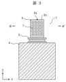
- FIG. 3 is a cross-sectional view of the temperature control device 1 in line BB'of FIG.
- the line AA' is a line parallel to the X direction
- the line BB' is a line parallel to the Y direction.
- FIG. 2 is a cross-sectional view taken along the ZX plane
- FIG. 3 is a cross-sectional view taken along the YZ plane.
- the temperature control block 2 is provided with a plurality of hollow portions 7 inside.
- the hollow portion 7 is a cavity provided at an arbitrary position inside the temperature control block 2, and air is present and does not communicate with the outside of the temperature control block 2.
- the hollow portion 7 has the effect of reducing the mass of the temperature control block 2 and accelerating the temperature change of the temperature control block 2.
- the hollow portions 7 are arranged in an orthogonal grid pattern at equal intervals inside the temperature control block 2.
- the arrangement of the hollow portions 7 inside the temperature control block 2 does not have to be orthogonal grids, and may not be evenly spaced.
- the size, number, and arrangement of the hollow portions 7 are not limited to the examples shown in FIGS. 2 and 3, and can be arbitrarily determined.
- the density is smaller, the heat capacity is smaller, and the temperature change is faster than the solid temperature control block 2 without the hollow portion 7.
- the density of the temperature control block 2 decreases as the volume occupied by the hollow portion 7 increases. For example, assuming that the volume ratio of the hollow portion 7 to the temperature control block 2 is 50%, the volume ratio of the material constituting the temperature control block 2 is 50% in the temperature control block 2, and it exists in the hollow portion 7. The percentage of the volume of air to be used is the remaining 50%.
- the density of the temperature control block 2 is calculated from the density of the material constituting the temperature control block 2 and the density of the air existing in the hollow portion 7. However, since the density of air is extremely smaller than the density of the materials constituting the temperature control block 2, the density of the temperature control block 2 can be obtained only from the density of the materials constituting the temperature control block 2.
- the density of the temperature control block 2 is reduced to 50% of the apparent density of the temperature control block 2.
- the apparent density is the density of the temperature control block 2 assuming that the hollow portion 7 is not provided, and is the size of the outer shape of the temperature control block 2 and the solid temperature control block 2 that does not have the hollow portion 7. It is a density calculated from the mass of.
- the heat capacity of the temperature control block 2 decreases as the density of the temperature control block 2 decreases.
- the temperature change of the temperature control block 2 due to the action of the temperature control unit 3 becomes faster by the decrease in the heat capacity.
- the volume ratio of the hollow portion 7 to the temperature control block 2 is 50% and the density of the temperature control block 2 is reduced to 50% of the apparent density, the heat capacity of the temperature control block 2 is in the absence of the hollow portion 7. It is reduced to 50% of the actual temperature control block 2. Then, the temperature change of the temperature control block 2 is 50% faster than the temperature change of the solid temperature control block 2 without the hollow portion 7.
- the temperature control block 2 since the hollow portion 7 does not communicate with the outside of the temperature control block 2, the surface area of the temperature control block 2 does not increase even if the hollow portion 7 is provided. When the surface area of the temperature control block 2 increases, heat exchange with the surrounding air is promoted, and the temperature change may be suppressed.
- the temperature control block 2 since the temperature control block 2 includes the hollow portion 7 without increasing the surface area, heat exchange between the temperature control block 2 and the surrounding air can be suppressed, and the temperature control block 2 can be suppressed. The temperature can be changed at high speed.
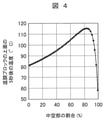
- FIG. 4 is a diagram showing an example of the result obtained by heat conduction analysis of the temperature change of the temperature control block 2.
- FIG. 4 shows a temperature change at the upper surface measurement point 2a of the temperature control block 2 when a heat amount of 10 W is input from the bottom surface to the aluminum temperature control block 2 having a width of 10 mm, a depth of 10 mm, and a height of 20 mm. The result of the calculation is shown.
- the upper surface measurement point 2a is the center point of the upper surface 2c (the surface opposite to the surface in contact with the temperature control portion 3) of the temperature control block 2.
- the horizontal axis shows the ratio of the volume of the hollow portion 7 to the temperature control block 2
- the vertical axis shows the temperature at the upper surface measurement point 2a 5 seconds after the heat quantity is input to the temperature control block 2. ..
- the temperature of the upper surface measurement point 2a of the temperature control block 2 after 5 seconds increases until the ratio of the hollow portion 7 increases to about 85%.
- the proportion of the hollow portion 7 exceeds 85%, the temperature of the upper surface measurement point 2a decreases as the proportion of the hollow portion 7 increases. This is because the thermal conductivity of the temperature control block 2 becomes smaller due to the higher proportion of the hollow portion 7, and the temperature of the upper surface measurement point 2a of the temperature control block 2 becomes less likely to rise. From this, the temperature of the temperature control block 2 can be changed at high speed by setting the ratio of the volume of the hollow portion 7 to the temperature control block 2 to an appropriate value according to the dimensions and materials of the temperature control block 2. Can be done.
- the temperature control block 2 provided with the hollow portion 7 be made of a material having a large thermal conductivity.
- a material having a large thermal conductivity such as aluminum, copper, or magnesium, or an alloy thereof.
- the material of the temperature control block 2 is not limited to the metal, and may be composed of a non-metal material having a large thermal conductivity, such as aluminum nitride or carbon fiber.
- the hollow portion 7 provided in the temperature control block 2 can have an arbitrary shape such as a rectangular parallelepiped shape, a polygonal pillar shape, a cylindrical shape, or a spherical shape.
- the plurality of hollow portions 7 may not all be isolated, and all or part of them may communicate with each other. Further, the hollow portion 7 may communicate with the outside of the temperature control block 2 through an opening provided on the surface of the temperature control block 2.
- the hollow portion 7 communicating with the outside of the temperature control block 2 can be easily formed.
- the hollow portion 7 does not have to be air, but may be a fluid other than air, for example, an inert gas such as nitrogen or a liquid (for example, oil or water).
- a heat insulating material made of a resin material or a porous material may be arranged in the hollow portion 7. Further, the inside of the hollow portion 7 may be a vacuum.
- an inert gas By filling the hollow portion 7 with an inert gas, oxidation of the surface of the hollow portion 7 can be prevented.
- the hollow portion 7 is filled with a liquid, the heat capacity of the temperature control block 2 can be adjusted with the liquid, and heat exchange can be efficiently performed to accelerate the temperature change of the temperature control block 2.
- By filling the hollow portion 7 with a heat insulating material or creating a vacuum heat conduction to the outside of the temperature control block 2 can be suppressed, and the temperature change of the temperature control block 2 can be accelerated.
- the size, number, and arrangement of the hollow portions 7 can be arbitrarily determined. Therefore, in the temperature control device 1 according to the present embodiment, the density (arrangement density) in which the hollow portion 7 is arranged is changed according to the position inside the temperature control block 2, thereby conducting heat conduction inside the temperature control block 2. , And the temperature change of the temperature control block 2 can be controlled according to the internal position of the temperature control block 2, so that the temperature of the temperature control block 2 can be changed with high accuracy.
- the hollow portion 7 can be formed by any method.
- a hole is made in the mass of the material constituting the temperature control block 2, or a partition member (partition wall) is installed in the space inside the box-shaped member constituting the temperature control block 2.
- a partition member partition wall
- a member having an arbitrary shape such as a grid-shaped plate-shaped member or a columnar member having a prismatic shape or a cylindrical shape can be used.
- the temperature control block 2 including the hollow portion 7 that does not communicate with the outside has an arbitrary method such as a method of joining a plurality of parts of the temperature control block 2 to each other, which has a recess that constitutes the hollow portion 7. It can be formed by a method.
- the temperature control block 2 since the temperature control block 2 includes the hollow portion 7 inside, the temperature of the temperature control block 2 can be changed at high speed and with high accuracy.
- the temperature control device 1 according to the second embodiment of the present invention will be described.
- the plurality of hollow portions 7 provided inside the temperature control block 2 form a honeycomb structure.
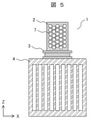
- FIG. 5 is a cross-sectional view showing an outline of the temperature control device 1 according to the second embodiment of the present invention, and is a cross-sectional view at the same position as in FIG.
- the plurality of hollow portions 7 provided inside the temperature control block 2 have a regular hexagonal prism shape and are arranged so as to form a honeycomb structure.
- the hollow portion 7 forms a honeycomb structure inside the temperature control block 2, the density becomes small, the heat capacity becomes small, and the strength can be maintained against the pressing pressure in the Z direction.
- the temperature control block 2 may be pressed in the Z direction toward the temperature control section 3 with a fastener or the like in order to reduce the contact thermal resistance with the temperature control section 3.
- the hollow portion 7 constitutes a honeycomb structure, even if the temperature control block 2 is pressed toward the temperature control portion 3 in the Z direction, the temperature control block 2 can maintain its strength without being crushed.
- the temperature of the temperature control block 2 can be changed at high speed and with high accuracy, and the contact thermal resistance between the temperature control block 2 and the temperature control unit 3 can be reduced. can.
- the temperature control block 2 includes a plurality of regions in which the arrangement densities of the hollow portions 7 are different from each other.
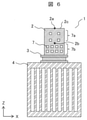
- FIG. 6 is a cross-sectional view showing an outline of the temperature control device 1 according to the third embodiment of the present invention, and is a cross-sectional view at the same position as in FIG.
- the temperature control block 2 internally includes two regions in which the arrangement densities of the hollow portions 7 are different from each other. That is, the temperature control block 2 includes a region 7a in which the arrangement density of the hollow portion 7 is low and a region 7b in which the arrangement density of the hollow portion 7 is high.
- the arrangement density of the hollow portion 7 differs depending on the distance from the temperature control portion 3, that is, in the vertical direction (Z direction) of the temperature control block 2.
- the region 7b having a high arrangement density of the hollow portion 7 is located at a position close to the temperature control portion 3, that is, a position adjacent to the temperature control portion 3 in the temperature control block 2.
- the region 7a having a low placement density of the hollow portion 7 is located at a position far from the temperature control portion 3 in the temperature control block 2, that is, between the region 7b having a high placement density of the hollow portion 7 and the upper surface 2c of the temperature control block 2. It is in a position (a position adjacent to the upper surface 2c of the temperature control block 2). Therefore, in the example shown in FIG. 6, the region 7b having a high placement density of the hollow portion 7 is located at the lower part of the temperature control block 2, and the region 7a having a low placement density of the hollow portion 7 is located at the upper part of the temperature control block 2. To position.
- the density that is, heat capacity
- heat conduction of the temperature control block 2 are changed depending on the position inside the temperature control block 2. You can change the rate.
- the temperature of the temperature control block 2 is changed by changing the arrangement density of the hollow portion 7 between the region near the temperature control portion 3 and the region far from the temperature control portion 3.
- the change can be accelerated, and the heat of the temperature control unit 3 can be uniformly transferred to the reaction solution in the reaction vessel placed on the temperature control block 2.
- the central measurement point 2b is a central position inside the temperature control block 2 between the region 7a where the placement density of the hollow portion 7 is low and the region 7b where the placement density of the hollow portion 7 is high.
- the temperature control block 2 has a higher density and a larger heat capacity than the region 7b where the placement density of the hollow portion 7 is high, but the volume ratio of the hollow portion 7 is lower. High thermal conductivity. Therefore, the temperature difference between the central measurement point 2b and the upper surface measurement point 2a of the temperature control block 2 can be reduced, and the temperature difference inside the temperature control block 2 can be reduced. Therefore, the temperature inside the temperature control block 2 becomes uniform, and the heat of the temperature control unit 3 can be uniformly transferred to the reaction solution in the reaction vessel placed on the temperature control block 2.
- the region 7b having a high placement density of the hollow portion 7 may be located at the upper part of the temperature control block 2, and the region 7a having a low placement density of the hollow portion 7 may be located at the lower part of the temperature control block 2.
- the arrangement density of the hollow portion 7 can be determined according to the temperature uniformity and the speed of temperature change required for the temperature control block 2. For example, the arrangement density of the hollow portion 7 takes into consideration the balance between the uniformity of the temperature at the lower part of the temperature control block 2 (the position close to the temperature control portion 3) and the speed of the temperature change in the entire temperature control block 2. Can be decided.
- the arrangement density of the hollow portion 7 may be different in the horizontal plane direction (inside the XY plane) of the temperature control block 2.
- the temperature control block 2 may place a plurality of reaction vessels in the XY plane. In this case, the arrangement density of the hollow portion 7 is changed in the XY plane so that the temperatures do not differ from each other depending on the reaction vessel. Can be.
- the number of regions in which the arrangement densities of the hollow portions 7 are different from each other is not limited to two, and may be three or more.
- the temperature control device 1 by changing the arrangement density of the hollow portion 7 inside the temperature control block 2, the density (that is, heat capacity) and thermal conductivity of the temperature control block 2 can be changed inside the temperature control block 2. It can be changed arbitrarily at the position of. Therefore, the temperature control device 1 according to the present embodiment can adjust the temperature distribution of the temperature control block 2 and can change the temperature of the temperature control block 2 at high speed and with high accuracy.
- the temperature control block 2 is provided with one or a plurality of recesses at the upper portion. A reaction vessel containing the reaction solution is placed in the recess.
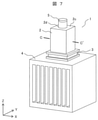
- FIG. 7 is a perspective view showing an outline of the temperature control device 1 according to the fourth embodiment of the present invention.
- FIG. 8 is a cross-sectional view of the temperature control device 1 in line CC'of FIG.
- the line CC' is a line parallel to the X direction.
- FIG. 8 is a cross-sectional view taken along the ZX plane.
- the temperature control block 2 is provided with one recess 2d at the top.
- a reaction vessel 5 containing the reaction solution 6 is placed in the recess 2d.
- the temperature control block 2 is provided with a plurality of hollow portions 7 inside, for example, as in the first embodiment (FIG. 2).
- the temperature control block 2 since the temperature control block 2 includes the recess 2d on which the reaction vessel 5 is placed and the hollow portion 7, the temperature change on the inner wall surface of the recess 2d is increased by the hollow portion 7. The heat generated in the temperature control unit 3 can be effectively transferred to the reaction solution 6 contained in the reaction vessel 5.
- the temperature control device 1 according to the fifth embodiment of the present invention will be described.
- the plurality of hollow portions 7 provided inside the temperature control block 2 communicate with each other.
- FIG. 9 is a cross-sectional view showing an outline of the temperature control device 1 according to the fifth embodiment of the present invention, and is a cross-sectional view at the same position as FIG.
- the plurality of hollow portions 7 provided inside the temperature control block 2 communicate with each other by the connecting portion 7c.
- the connecting portion 7c is a cavity that connects a plurality of hollow portions 7 to each other.
- FIG. 9 shows, as an example, the temperature control block 2 provided with the recess 2d described in the fourth embodiment (FIG. 8).
- FIG. 10 is a cross-sectional view of the temperature control device 1 in line DD'of FIG. Lines DD'are parallel to the Z direction.
- FIG. 10 is a cross-sectional view taken along the YZ plane.
- the hollow portions 7 communicate with each other by the connecting portions 7c in the X direction, the Y direction, and the Z direction, respectively.
- the hollow portions 7 communicating with each other by the connecting portions 7c are easy to form. Further, when the hollow portion 7 communicates with each other by the connecting portion 7c, the work of filling the hollow portion 7 with a fluid (for example, air, an inert gas, or a liquid) or creating a vacuum can be easily performed. Can be done. Further, when the hollow portion 7 is filled with a fluid, the hollow portion 7 connected by the connecting portion 7c can be uniformly filled. In the examples shown in FIGS. 9 and 10, the size (cross-sectional area) of the connecting portion 7c is smaller than the size (cross-sectional area) of the hollow portion 7.
- a fluid for example, air, an inert gas, or a liquid
- not all the hollow portions 7 may communicate with each other by the connecting portion 7c, and only a specific part of the hollow portions 7 may communicate with each other by the connecting portion 7c.
- the size (cross-sectional area) of the connecting portion 7c can be arbitrarily determined, and may be equal to or different from the size (cross-sectional area) of the hollow portion 7.
- the size of the connecting portion 7c may be equal to the size of the hollow portion 7, and the hollow portion 7 may communicate inside the temperature control block 2 without changing the size.
- the temperature control device 1 according to the sixth embodiment of the present invention will be described.
- the plurality of hollow portions 7 provided inside the temperature control block 2 communicate with each other and communicate with the outside of the temperature control block 2.
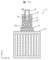
- FIG. 11 is a cross-sectional view showing an outline of the temperature control device 1 according to the sixth embodiment of the present invention, and is a cross-sectional view at the same position as in FIG.
- the temperature control block 2 is provided with an opening 7d on the surface.
- FIG. 11 shows, as an example, the temperature control block 2 provided with the recess 2d described in the fourth embodiment (FIG. 8).
- the plurality of hollow portions 7 provided inside the temperature control block 2 communicate with each other by the connecting portion 7c, and communicate with the outside of the temperature control block 2 from the opening 7d.
- the opening 7d can be provided at an arbitrary position on the surface of the temperature control block 2.
- the hollow portion 7 When the hollow portion 7 communicates with the outside of the temperature control block 2, the hollow portion 7 can be easily formed as described in the first embodiment. Further, it is possible to easily fill the hollow portion 7 with a fluid (for example, an inert gas or a liquid), arrange a heat insulating material, or evacuate the inside of the hollow portion 7. ..
- a fluid for example, an inert gas or a liquid
- the temperature control block 2 includes a plurality of regions in which the arrangement densities of the hollow portions 7 are different from each other.
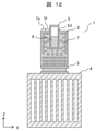
- FIG. 12 is a cross-sectional view showing an outline of the temperature control device 1 according to the seventh embodiment of the present invention, and is a cross-sectional view at the same position as in FIG.
- the temperature control block 2 internally includes two regions in which the arrangement densities of the hollow portions 7 are different from each other. That is, the temperature control block 2 includes a region 7e in which the arrangement density of the hollow portion 7 is high and a region 7f in which the arrangement density of the hollow portion 7 is low.
- FIG. 12 shows, as an example, the temperature control block 2 provided with the recess 2d described in the fourth embodiment (FIG. 8).
- the arrangement density of the hollow portion 7 differs depending on the distance from the recess 2d, that is, the distance from the reaction vessel 5 containing the reaction solution 6. In other words, the arrangement density of the hollow portion 7 differs in the horizontal plane direction (inside the XY plane) of the temperature control block 2.
- the region 7f having a low placement density of the hollow portion 7 is located in the temperature control block 2 at a position close to the recess 2d (or the reaction vessel 5), that is, a position adjacent to the recess 2d (or the reaction vessel 5).
- the region 7e having a high placement density of the hollow portion 7 is located in the temperature control block 2 at a position far from the recess 2d (or the reaction vessel 5), that is, a position adjacent to the region 7f where the placement density of the hollow portion 7 is low. Therefore, the region 7f having a low placement density of the hollow portion 7 is located closer to the recess 2d (or the reaction vessel 5) than the region 7e having a high placement density of the hollow portion 7. In the example shown in FIG. 12, the region 7f having a low placement density of the hollow portion 7 is located in the central portion of the temperature control block 2, and the region 7e having a high placement density of the hollow portion 7 is located at the peripheral portion of the temperature control block 2. To position.
- the region 7f in which the arrangement density of the hollow portion 7 is low is located near the reaction vessel 5, so that the thermal conductivity of the temperature control block 2 is large at the position close to the reaction vessel 5.
- the temperature of the contact surface between the temperature control block 2 and the reaction vessel 5 can be kept uniform, and the heat of the temperature control unit 3 can be uniformly transferred to the reaction solution 6 contained in the reaction vessel 5.
- the region 7e having a high arrangement density of the hollow portion 7 is located at a position far from the reaction vessel 5, the temperature control block 2 has a smaller density and a smaller heat capacity at a position far from the reaction vessel 5, and the temperature changes. Becomes faster.
- the region 7e having a high arrangement density of the hollow portion 7 is located at the peripheral edge portion of the temperature control block 2, and the thermal conductivity of the temperature control block 2 at this position is reduced. Therefore, in the temperature control block 2, the thermal resistance from the region 7f where the arrangement density of the hollow portion 7 is low to the region 7e where the arrangement density of the hollow portion 7 is high increases, so that heat dissipation from the surface to the outside air can be suppressed. , The temperature change becomes even faster.
- the temperature control block 2 includes a plurality of regions in which the arrangement densities of the hollow portions 7 are different from each other.
- FIG. 13 is a cross-sectional view showing an outline of the temperature control device 1 according to the eighth embodiment of the present invention, and is a cross-sectional view at the same position as in FIG.
- the temperature control block 2 internally includes two regions in which the arrangement densities of the hollow portions 7 are different from each other. That is, the temperature control block 2 includes a region 7g in which the arrangement density of the hollow portion 7 is low and a region 7h in which the arrangement density of the hollow portion 7 is high.
- FIG. 12 shows, as an example, the temperature control block 2 provided with the recess 2d described in the fourth embodiment (FIG. 8).
- the arrangement density of the hollow portion 7 is different above and below the position of the liquid level of the reaction solution 6 contained in the reaction vessel 5 placed in the recess 2d.
- the region 7g in which the arrangement density of the hollow portion 7 is low is below the position of the liquid level of the reaction solution 6 contained in the reaction vessel 5 in the temperature control block 2.
- the region 7h having a high arrangement density of the hollow portion 7 is above the position of the liquid surface of the reaction solution 6 in the temperature control block 2. Therefore, in the example shown in FIG. 13, the region 7g having a low placement density of the hollow portion 7 is located at the lower part of the temperature control block 2, and the region 7h having a high placement density of the hollow portion 7 is located at the upper part of the temperature control block 2. To position.
- the position of the liquid level of the reaction solution 6 contained in the reaction vessel 5 differs depending on the reaction vessel 5 and the reaction solution 6, but the approximate position can be determined in advance. Therefore, the position of the boundary in the vertical direction (Z direction) between the region 7g having a low placement density of the hollow portion and the region 7h having a high placement density of the hollow portion is the approximate position of the liquid surface of the reaction solution 6, and the reaction vessel 5 is used. And can be determined in advance based on the information about the reaction solution 6.
- the region 7h having a high arrangement density of the hollow portion 7 has a large volume ratio of the hollow portion 7 to the temperature control block 2, and the thermal conductivity of the temperature control block 2 is small, so that the temperature control block 2 has a small volume.
- the ratio of the volume of the hollow portion 7 to the temperature control block 2 exceeds 85% as shown in FIG. 4, and the thermal conductivity of the temperature control block 2 is high. Is the area where becomes smaller.
- the temperature control block 2 is a region 7 g in which the arrangement density of the hollow portion 7 is low below the position of the liquid surface of the reaction solution 6, the thermal conductivity is large, and the temperature change is fast. Therefore, the heat of the temperature control unit 3 can be quickly transferred to the reaction solution 6.
- the temperature control block 2 is a region 7h where the arrangement density of the hollow portion 7 is high above the position of the liquid surface of the reaction solution 6, and the thermal conductivity is small and the temperature change is slow. Heat dissipation from 2c can be suppressed, and the temperature change in the entire temperature control block 2 can be made even faster.
- the temperature control block 2 includes one or a plurality of tubular hollow portions 7 inside.
- the hollow portion 7 has a tubular shape extending in the Z direction (vertical direction), and can take any shape such as a square tubular shape or a cylindrical shape.
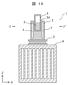
- FIG. 14 is a cross-sectional view showing an outline of the temperature control device 1 according to the ninth embodiment of the present invention, and is a cross-sectional view at the same position as FIG.
- FIG. 14 shows, as an example, a temperature control block 2 having one cylindrical hollow portion 7 inside.
- the cylindrical hollow portion 7 is provided on the peripheral edge portion (outer peripheral portion) of the temperature control block 2.
- FIG. 14 shows, as an example, the temperature control block 2 provided with the recess 2d described in the fourth embodiment (FIG. 8).
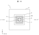
- FIG. 15 is a cross-sectional view of the temperature control device 1 in a horizontal plane (XY plane) passing through the line FF'of FIG.
- the hollow portion 7 has a square tube shape and is provided on the peripheral edge portion of the temperature control block 2.
- the tubular hollow portion 7 surrounds the periphery of the recess 2d and surrounds the reaction vessel 5 placed in the recess 2d.
- the temperature control block 2 since the temperature control block 2 includes a tubular hollow portion 7 that surrounds the periphery of the recess 2d (or the reaction vessel 5), the heat from the recess 2d to the outside of the temperature control block 2 is provided.
- the conductivity becomes smaller, the thermal resistance increases, and heat dissipation from the surface to the outside air can be suppressed. Therefore, the temperature control block 2 can suppress the amount of heat radiated from the side surface, and the temperature change of the entire temperature control block 2 can be made even faster.
- the temperature control device 1 according to the tenth embodiment of the present invention will be described.
- the temperature control block 2 is provided with a plurality of hollow portions 7 in the lower portion in contact with the temperature control section 3.
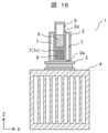
- FIG. 16 is a cross-sectional view showing an outline of the temperature control device 1 according to the tenth embodiment of the present invention, and is a cross-sectional view at the same position as FIG. Note that FIG. 16 shows, as an example, the temperature control block 2 including the cylindrical hollow portion 7 surrounding the periphery of the recess 2d (or the reaction vessel 5) described in the ninth embodiment (FIG. 14).
- the temperature control block 2 includes the recess 2d described in the fourth embodiment (FIG. 8).
- a reaction vessel 5 containing the reaction solution 6 is placed in the recess 2d.
- the temperature control block 2 is provided with a plurality of hollow portions 7 (7n) in the lower portion in contact with the temperature control portion 3, more specifically, between the bottom surface 2e in contact with the temperature control portion 3 and the lower portion of the recess 2d.
- the temperature control block 2 includes a heat conduction path 8 from the temperature control portion 3 to the recess 2d (that is, the reaction vessel 5) between the plurality of hollow portions 7n.
- the plurality of hollow portions 7n are located between the temperature control portion 3 and the recess 2d in the temperature control block 2, and extend upward from the portion of the temperature control block 2 in contact with the temperature control portion 3 toward the recess 2d. ..
- the hollow portions 7n are stretched between each other so as to connect the temperature control portion 3 and the recess 2d, and form a heat conduction path 8 from the temperature control portion 3 to the recess 2d.
- the temperature control block 2 may or may not be provided with a plurality of cylindrical hollow portions 7 surrounding the periphery of the recess 2d (or the reaction vessel 5).
- the temperature control block 2 is provided with a plurality of hollow portions 7n in the lower portion in contact with the temperature control portion 3, and is provided with a heat conduction path 8 extending upward from the bottom surface 2e, thereby reducing the heat capacity of the temperature control block 2 and reducing the heat capacity of the temperature control block 2. ,
- the heat conduction distance from the temperature control unit 3 to the reaction vessel 5 can be shortened. Therefore, the temperature control block 2 can efficiently transfer the heat generated in the temperature control unit 3 to the reaction vessel 5, and the temperature change of the reaction vessel 5 can be made faster.
- the present invention is not limited to the above embodiment, and various modifications are possible.
- the above-described embodiment has been described in detail in order to explain the present invention in an easy-to-understand manner, and the present invention is not necessarily limited to the embodiment including all the described configurations.
Landscapes
- Chemical & Material Sciences (AREA)
- Life Sciences & Earth Sciences (AREA)
- Health & Medical Sciences (AREA)
- Organic Chemistry (AREA)
- Engineering & Computer Science (AREA)
- Zoology (AREA)
- Wood Science & Technology (AREA)
- Bioinformatics & Cheminformatics (AREA)
- Biochemistry (AREA)
- General Health & Medical Sciences (AREA)
- Biotechnology (AREA)
- Chemical Kinetics & Catalysis (AREA)
- General Engineering & Computer Science (AREA)
- Genetics & Genomics (AREA)
- Microbiology (AREA)
- Physics & Mathematics (AREA)
- Proteomics, Peptides & Aminoacids (AREA)
- Analytical Chemistry (AREA)
- Molecular Biology (AREA)
- Sustainable Development (AREA)
- Biomedical Technology (AREA)
- Biophysics (AREA)
- Thermal Sciences (AREA)
- Immunology (AREA)
- Clinical Laboratory Science (AREA)
- Medicinal Chemistry (AREA)
- Control Of Temperature (AREA)
- Apparatus Associated With Microorganisms And Enzymes (AREA)
- Measuring Or Testing Involving Enzymes Or Micro-Organisms (AREA)
- Physical Or Chemical Processes And Apparatus (AREA)
Abstract
Description
Claims (11)
- 溶液を収容した容器を載置可能な温度調節ブロックと、
前記温度調節ブロックに接触するように設置され、前記溶液の温度を変化させる温度調節部と、
を備え、
前記温度調節ブロックは、1つまたは複数の中空部を内部に備える、
ことを特徴とする温度制御装置。 - 前記温度調節ブロックは、複数の前記中空部を備え、
前記中空部は、ハニカム構造を構成するように並んでいる、
請求項1に記載の温度制御装置。 - 前記温度調節ブロックは、複数の前記中空部を備え、前記中空部の配置される密度が互いに異なる複数の領域を内部に備える、
請求項1に記載の温度制御装置。 - 前記温度調節ブロックは、前記溶液を収容した前記容器が載置される凹部を上部に備える、
請求項1に記載の温度制御装置。 - 前記温度調節ブロックは、複数の前記中空部を備え、
複数の前記中空部は、互いに連通している、
請求項1に記載の温度制御装置。 - 前記温度調節ブロックは、複数の前記中空部を備え、
前記中空部は、直交格子状に並んでいる、
請求項1に記載の温度制御装置。 - 前記温度調節ブロックは、複数の前記中空部を備えるとともに、表面に開口部を備え、
複数の前記中空部は、互いに連通しており、前記開口部から前記温度調節ブロックの外部に連通している、
請求項1に記載の温度制御装置。 - 前記温度調節ブロックは、複数の前記中空部を備えるとともに、前記溶液を収容した前記容器が載置される凹部を上部に備え、
前記中空部の配置される密度は、前記凹部からの距離により異なる、
請求項1に記載の温度制御装置。 - 前記温度調節ブロックは、複数の前記中空部を備えるとともに、前記溶液を収容した前記容器が載置される凹部を上部に備え、
前記中空部の配置される密度は、前記凹部に載置された前記容器に収容された前記溶液の液面の位置として予め定められた位置より上方と下方で異なる、
請求項1に記載の温度制御装置。 - 前記温度調節ブロックは、前記溶液を収容した前記容器が載置される凹部を上部に備えるとともに、筒状の前記中空部を内部に備え、
筒状の前記中空部は、前記凹部の周囲を囲む、
請求項1に記載の温度制御装置。 - 前記温度調節ブロックは、前記溶液を収容した前記容器が載置される凹部を上部に備えるとともに、前記温度調節部と前記凹部との間に複数の前記中空部を備え、
前記中空部は、前記温度調節ブロックの前記温度調節部と接触する部分から前記凹部に向かって延伸し、
前記中空部の互いの間は、前記温度調節部と前記凹部とを接続するように延伸する、
請求項1に記載の温度制御装置。
Priority Applications (7)
| Application Number | Priority Date | Filing Date | Title |
|---|---|---|---|
| US18/018,622 US20230294101A1 (en) | 2020-09-02 | 2020-09-02 | Temperature Control Device |
| CN202080104070.5A CN115997031A (zh) | 2020-09-02 | 2020-09-02 | 温度控制装置 |
| KR1020237002747A KR20230028493A (ko) | 2020-09-02 | 2020-09-02 | 온도 제어 장치 |
| EP20952418.0A EP4209574A4 (en) | 2020-09-02 | 2020-09-02 | Temperature control device |
| JP2022546783A JP7488904B2 (ja) | 2020-09-02 | 2020-09-02 | 温度制御装置 |
| PCT/JP2020/033303 WO2022049678A1 (ja) | 2020-09-02 | 2020-09-02 | 温度制御装置 |
| TW110130109A TWI801966B (zh) | 2020-09-02 | 2021-08-16 | 溫度控制裝置 |
Applications Claiming Priority (1)
| Application Number | Priority Date | Filing Date | Title |
|---|---|---|---|
| PCT/JP2020/033303 WO2022049678A1 (ja) | 2020-09-02 | 2020-09-02 | 温度制御装置 |
Publications (1)
| Publication Number | Publication Date |
|---|---|
| WO2022049678A1 true WO2022049678A1 (ja) | 2022-03-10 |
Family
ID=80491856
Family Applications (1)
| Application Number | Title | Priority Date | Filing Date |
|---|---|---|---|
| PCT/JP2020/033303 Ceased WO2022049678A1 (ja) | 2020-09-02 | 2020-09-02 | 温度制御装置 |
Country Status (7)
| Country | Link |
|---|---|
| US (1) | US20230294101A1 (ja) |
| EP (1) | EP4209574A4 (ja) |
| JP (1) | JP7488904B2 (ja) |
| KR (1) | KR20230028493A (ja) |
| CN (1) | CN115997031A (ja) |
| TW (1) | TWI801966B (ja) |
| WO (1) | WO2022049678A1 (ja) |
Citations (3)
| Publication number | Priority date | Publication date | Assignee | Title |
|---|---|---|---|---|
| JP2010502228A (ja) * | 2006-09-06 | 2010-01-28 | アプライド バイオシステムズ, エルエルシー | 化学的または生物学的反応を実行するためのデバイス |
| JP2014518758A (ja) * | 2011-05-06 | 2014-08-07 | バイオ−ラッド ラボラトリーズ インコーポレーティッド | 迅速な温度変化のためのベイパーチャンバーを備えたサーマルサイクラー |
| WO2019193806A1 (ja) * | 2018-04-02 | 2019-10-10 | 株式会社日立ハイテクノロジーズ | 温度制御装置、及び遺伝子検査装置 |
Family Cites Families (11)
| Publication number | Priority date | Publication date | Assignee | Title |
|---|---|---|---|---|
| US6703236B2 (en) * | 1990-11-29 | 2004-03-09 | Applera Corporation | Thermal cycler for automatic performance of the polymerase chain reaction with close temperature control |
| KR100236506B1 (ko) * | 1990-11-29 | 2000-01-15 | 퍼킨-엘머시터스인스트루먼츠 | 폴리머라제 연쇄 반응 수행 장치 |
| DE29623597U1 (de) * | 1996-11-08 | 1999-01-07 | Eppendorf - Netheler - Hinz Gmbh, 22339 Hamburg | Temperierblock mit Temperiereinrichtungen |
| US7632464B2 (en) * | 2006-06-29 | 2009-12-15 | Bio-Rad Laboratories, Inc. | Low-mass sample block with rapid response to temperature change |
| JP5251882B2 (ja) * | 2007-10-26 | 2013-07-31 | 凸版印刷株式会社 | 反応チップ及び反応方法、遺伝子処理装置用温度調節機構及び遺伝子処理装置 |
| CN102164674B (zh) | 2008-09-23 | 2014-07-16 | 皇家飞利浦电子股份有限公司 | 热循环设备 |
| CN102917796B (zh) * | 2010-04-20 | 2015-04-01 | 科贝特研究私人有限公司 | 温度控制方法和设备 |
| JP6803030B2 (ja) * | 2015-12-01 | 2020-12-23 | 日本板硝子株式会社 | Pcr方法 |
| US11602752B2 (en) * | 2016-06-30 | 2023-03-14 | Seegene, Inc. | Apparatus for amplificating nucleic acid and fluorescence-detecting device |
| US11173491B2 (en) * | 2017-01-25 | 2021-11-16 | U-gene & Cell Co. | Apparatus for high-speed nucleic acid amplification and method for temperature control of nucleic acid amplification reaction |
| CN108998371A (zh) * | 2018-09-28 | 2018-12-14 | 北京金豪制药股份有限公司 | 一种低压磁感应加热的pcr控温装置 |
-
2020
- 2020-09-02 EP EP20952418.0A patent/EP4209574A4/en active Pending
- 2020-09-02 WO PCT/JP2020/033303 patent/WO2022049678A1/ja not_active Ceased
- 2020-09-02 US US18/018,622 patent/US20230294101A1/en active Pending
- 2020-09-02 JP JP2022546783A patent/JP7488904B2/ja active Active
- 2020-09-02 CN CN202080104070.5A patent/CN115997031A/zh active Pending
- 2020-09-02 KR KR1020237002747A patent/KR20230028493A/ko not_active Ceased
-
2021
- 2021-08-16 TW TW110130109A patent/TWI801966B/zh active
Patent Citations (3)
| Publication number | Priority date | Publication date | Assignee | Title |
|---|---|---|---|---|
| JP2010502228A (ja) * | 2006-09-06 | 2010-01-28 | アプライド バイオシステムズ, エルエルシー | 化学的または生物学的反応を実行するためのデバイス |
| JP2014518758A (ja) * | 2011-05-06 | 2014-08-07 | バイオ−ラッド ラボラトリーズ インコーポレーティッド | 迅速な温度変化のためのベイパーチャンバーを備えたサーマルサイクラー |
| WO2019193806A1 (ja) * | 2018-04-02 | 2019-10-10 | 株式会社日立ハイテクノロジーズ | 温度制御装置、及び遺伝子検査装置 |
Non-Patent Citations (1)
| Title |
|---|
| See also references of EP4209574A4 * |
Also Published As
| Publication number | Publication date |
|---|---|
| JPWO2022049678A1 (ja) | 2022-03-10 |
| KR20230028493A (ko) | 2023-02-28 |
| TW202210983A (zh) | 2022-03-16 |
| US20230294101A1 (en) | 2023-09-21 |
| EP4209574A1 (en) | 2023-07-12 |
| TWI801966B (zh) | 2023-05-11 |
| JP7488904B2 (ja) | 2024-05-22 |
| CN115997031A (zh) | 2023-04-21 |
| EP4209574A4 (en) | 2024-04-17 |
Similar Documents
| Publication | Publication Date | Title |
|---|---|---|
| EP2076605B2 (en) | Cooling in a thermal cycler using heat pipes | |
| KR100938374B1 (ko) | 다수의 샘플을 포함하는 블럭의 열순환 장치, 시스템 및 방법 | |
| US9718061B2 (en) | Instruments and method relating to thermal cycling | |
| EP0545736A2 (en) | Method and apparatus for temperature control of multiple samples | |
| US20070184548A1 (en) | Device for carrying out chemical or biological reactions | |
| US20120240597A1 (en) | Temperature control apparatus for samples storage | |
| CN112912721B (zh) | 高样本通量差示扫描量热仪 | |
| JP4977138B2 (ja) | 最適化されたサンプルホルダ形状を有するサーマルサイクラー | |
| JP4829252B2 (ja) | 異なる熱容量を有する微小流体試料用の温度制御装置 | |
| EP3524353A1 (en) | Device for thermocycling biological samples, monitoring instrument comprising the same, and method for thermocycling biological samples using such device | |
| JP7488904B2 (ja) | 温度制御装置 | |
| CN103374510A (zh) | 一种基于低熔点金属液滴的pcr反应装置及其实施方法 | |
| US20080314557A1 (en) | Thermoelectric device and heat sink assembly with reduced edge heat loss | |
| JP5761767B2 (ja) | 温度制御装置、及び温度素子 | |
| EP4725600A1 (en) | Nucleic acid amplification in droplets | |
| US12478969B2 (en) | Device for heating sample | |
| JP2009112934A (ja) | 反応容器の温度制御装置 |
Legal Events
| Date | Code | Title | Description |
|---|---|---|---|
| 121 | Ep: the epo has been informed by wipo that ep was designated in this application |
Ref document number: 20952418 Country of ref document: EP Kind code of ref document: A1 |
|
| ENP | Entry into the national phase |
Ref document number: 2022546783 Country of ref document: JP Kind code of ref document: A |
|
| ENP | Entry into the national phase |
Ref document number: 20237002747 Country of ref document: KR Kind code of ref document: A |
|
| NENP | Non-entry into the national phase |
Ref country code: DE |
|
| ENP | Entry into the national phase |
Ref document number: 2020952418 Country of ref document: EP Effective date: 20230403 |