WO2022049763A1 - 空気調和装置 - Google Patents
空気調和装置 Download PDFInfo
- Publication number
- WO2022049763A1 WO2022049763A1 PCT/JP2020/033759 JP2020033759W WO2022049763A1 WO 2022049763 A1 WO2022049763 A1 WO 2022049763A1 JP 2020033759 W JP2020033759 W JP 2020033759W WO 2022049763 A1 WO2022049763 A1 WO 2022049763A1
- Authority
- WO
- WIPO (PCT)
- Prior art keywords
- indoor
- flow rate
- control device
- heat medium
- relay
- Prior art date
- Legal status (The legal status is an assumption and is not a legal conclusion. Google has not performed a legal analysis and makes no representation as to the accuracy of the status listed.)
- Ceased
Links
Images

Classifications
-
- F—MECHANICAL ENGINEERING; LIGHTING; HEATING; WEAPONS; BLASTING
- F24—HEATING; RANGES; VENTILATING
- F24F—AIR-CONDITIONING; AIR-HUMIDIFICATION; VENTILATION; USE OF AIR CURRENTS FOR SCREENING
- F24F11/00—Control or safety arrangements
- F24F11/70—Control systems characterised by their outputs; Constructional details thereof
- F24F11/80—Control systems characterised by their outputs; Constructional details thereof for controlling the temperature of the supplied air
- F24F11/83—Control systems characterised by their outputs; Constructional details thereof for controlling the temperature of the supplied air by controlling the supply of heat-exchange fluids to heat-exchangers
- F24F11/84—Control systems characterised by their outputs; Constructional details thereof for controlling the temperature of the supplied air by controlling the supply of heat-exchange fluids to heat-exchangers using valves
-
- F—MECHANICAL ENGINEERING; LIGHTING; HEATING; WEAPONS; BLASTING
- F24—HEATING; RANGES; VENTILATING
- F24F—AIR-CONDITIONING; AIR-HUMIDIFICATION; VENTILATION; USE OF AIR CURRENTS FOR SCREENING
- F24F11/00—Control or safety arrangements
- F24F11/70—Control systems characterised by their outputs; Constructional details thereof
- F24F11/80—Control systems characterised by their outputs; Constructional details thereof for controlling the temperature of the supplied air
- F24F11/83—Control systems characterised by their outputs; Constructional details thereof for controlling the temperature of the supplied air by controlling the supply of heat-exchange fluids to heat-exchangers
- F24F11/85—Control systems characterised by their outputs; Constructional details thereof for controlling the temperature of the supplied air by controlling the supply of heat-exchange fluids to heat-exchangers using variable-flow pumps
-
- F—MECHANICAL ENGINEERING; LIGHTING; HEATING; WEAPONS; BLASTING
- F24—HEATING; RANGES; VENTILATING
- F24F—AIR-CONDITIONING; AIR-HUMIDIFICATION; VENTILATION; USE OF AIR CURRENTS FOR SCREENING
- F24F1/00—Room units for air-conditioning, e.g. separate or self-contained units or units receiving primary air from a central station
- F24F1/0007—Indoor units, e.g. fan coil units
- F24F1/0068—Indoor units, e.g. fan coil units characterised by the arrangement of refrigerant piping outside the heat exchanger within the unit casing
-
- F—MECHANICAL ENGINEERING; LIGHTING; HEATING; WEAPONS; BLASTING
- F25—REFRIGERATION OR COOLING; COMBINED HEATING AND REFRIGERATION SYSTEMS; HEAT PUMP SYSTEMS; MANUFACTURE OR STORAGE OF ICE; LIQUEFACTION SOLIDIFICATION OF GASES
- F25B—REFRIGERATION MACHINES, PLANTS OR SYSTEMS; COMBINED HEATING AND REFRIGERATION SYSTEMS; HEAT PUMP SYSTEMS
- F25B13/00—Compression machines, plants or systems, with reversible cycle
-
- F—MECHANICAL ENGINEERING; LIGHTING; HEATING; WEAPONS; BLASTING
- F25—REFRIGERATION OR COOLING; COMBINED HEATING AND REFRIGERATION SYSTEMS; HEAT PUMP SYSTEMS; MANUFACTURE OR STORAGE OF ICE; LIQUEFACTION SOLIDIFICATION OF GASES
- F25B—REFRIGERATION MACHINES, PLANTS OR SYSTEMS; COMBINED HEATING AND REFRIGERATION SYSTEMS; HEAT PUMP SYSTEMS
- F25B49/00—Arrangement or mounting of control or safety devices
- F25B49/02—Arrangement or mounting of control or safety devices for compression type machines, plants or systems
-
- F—MECHANICAL ENGINEERING; LIGHTING; HEATING; WEAPONS; BLASTING
- F24—HEATING; RANGES; VENTILATING
- F24F—AIR-CONDITIONING; AIR-HUMIDIFICATION; VENTILATION; USE OF AIR CURRENTS FOR SCREENING
- F24F2140/00—Control inputs relating to system states
- F24F2140/10—Pressure
- F24F2140/12—Heat-exchange fluid pressure
-
- F—MECHANICAL ENGINEERING; LIGHTING; HEATING; WEAPONS; BLASTING
- F24—HEATING; RANGES; VENTILATING
- F24F—AIR-CONDITIONING; AIR-HUMIDIFICATION; VENTILATION; USE OF AIR CURRENTS FOR SCREENING
- F24F2140/00—Control inputs relating to system states
- F24F2140/20—Heat-exchange fluid temperature
-
- F—MECHANICAL ENGINEERING; LIGHTING; HEATING; WEAPONS; BLASTING
- F25—REFRIGERATION OR COOLING; COMBINED HEATING AND REFRIGERATION SYSTEMS; HEAT PUMP SYSTEMS; MANUFACTURE OR STORAGE OF ICE; LIQUEFACTION SOLIDIFICATION OF GASES
- F25B—REFRIGERATION MACHINES, PLANTS OR SYSTEMS; COMBINED HEATING AND REFRIGERATION SYSTEMS; HEAT PUMP SYSTEMS
- F25B2313/00—Compression machines, plants or systems with reversible cycle not otherwise provided for
- F25B2313/003—Indoor unit with water as a heat sink or heat source
-
- F—MECHANICAL ENGINEERING; LIGHTING; HEATING; WEAPONS; BLASTING
- F25—REFRIGERATION OR COOLING; COMBINED HEATING AND REFRIGERATION SYSTEMS; HEAT PUMP SYSTEMS; MANUFACTURE OR STORAGE OF ICE; LIQUEFACTION SOLIDIFICATION OF GASES
- F25B—REFRIGERATION MACHINES, PLANTS OR SYSTEMS; COMBINED HEATING AND REFRIGERATION SYSTEMS; HEAT PUMP SYSTEMS
- F25B2600/00—Control issues
- F25B2600/02—Compressor control
- F25B2600/025—Compressor control by controlling speed
-
- F—MECHANICAL ENGINEERING; LIGHTING; HEATING; WEAPONS; BLASTING
- F25—REFRIGERATION OR COOLING; COMBINED HEATING AND REFRIGERATION SYSTEMS; HEAT PUMP SYSTEMS; MANUFACTURE OR STORAGE OF ICE; LIQUEFACTION SOLIDIFICATION OF GASES
- F25B—REFRIGERATION MACHINES, PLANTS OR SYSTEMS; COMBINED HEATING AND REFRIGERATION SYSTEMS; HEAT PUMP SYSTEMS
- F25B2600/00—Control issues
- F25B2600/23—Time delays
-
- F—MECHANICAL ENGINEERING; LIGHTING; HEATING; WEAPONS; BLASTING
- F25—REFRIGERATION OR COOLING; COMBINED HEATING AND REFRIGERATION SYSTEMS; HEAT PUMP SYSTEMS; MANUFACTURE OR STORAGE OF ICE; LIQUEFACTION SOLIDIFICATION OF GASES
- F25B—REFRIGERATION MACHINES, PLANTS OR SYSTEMS; COMBINED HEATING AND REFRIGERATION SYSTEMS; HEAT PUMP SYSTEMS
- F25B2700/00—Sensing or detecting of parameters; Sensors therefor
- F25B2700/21—Temperatures
- F25B2700/2106—Temperatures of fresh outdoor air
-
- F—MECHANICAL ENGINEERING; LIGHTING; HEATING; WEAPONS; BLASTING
- F25—REFRIGERATION OR COOLING; COMBINED HEATING AND REFRIGERATION SYSTEMS; HEAT PUMP SYSTEMS; MANUFACTURE OR STORAGE OF ICE; LIQUEFACTION SOLIDIFICATION OF GASES
- F25B—REFRIGERATION MACHINES, PLANTS OR SYSTEMS; COMBINED HEATING AND REFRIGERATION SYSTEMS; HEAT PUMP SYSTEMS
- F25B2700/00—Sensing or detecting of parameters; Sensors therefor
- F25B2700/21—Temperatures
- F25B2700/2116—Temperatures of a condenser
- F25B2700/21162—Temperatures of a condenser of the refrigerant at the inlet of the condenser
-
- F—MECHANICAL ENGINEERING; LIGHTING; HEATING; WEAPONS; BLASTING
- F25—REFRIGERATION OR COOLING; COMBINED HEATING AND REFRIGERATION SYSTEMS; HEAT PUMP SYSTEMS; MANUFACTURE OR STORAGE OF ICE; LIQUEFACTION SOLIDIFICATION OF GASES
- F25B—REFRIGERATION MACHINES, PLANTS OR SYSTEMS; COMBINED HEATING AND REFRIGERATION SYSTEMS; HEAT PUMP SYSTEMS
- F25B2700/00—Sensing or detecting of parameters; Sensors therefor
- F25B2700/21—Temperatures
- F25B2700/2116—Temperatures of a condenser
- F25B2700/21163—Temperatures of a condenser of the refrigerant at the outlet of the condenser
-
- F—MECHANICAL ENGINEERING; LIGHTING; HEATING; WEAPONS; BLASTING
- F25—REFRIGERATION OR COOLING; COMBINED HEATING AND REFRIGERATION SYSTEMS; HEAT PUMP SYSTEMS; MANUFACTURE OR STORAGE OF ICE; LIQUEFACTION SOLIDIFICATION OF GASES
- F25B—REFRIGERATION MACHINES, PLANTS OR SYSTEMS; COMBINED HEATING AND REFRIGERATION SYSTEMS; HEAT PUMP SYSTEMS
- F25B2700/00—Sensing or detecting of parameters; Sensors therefor
- F25B2700/21—Temperatures
- F25B2700/2117—Temperatures of an evaporator
- F25B2700/21174—Temperatures of an evaporator of the refrigerant at the inlet of the evaporator
-
- F—MECHANICAL ENGINEERING; LIGHTING; HEATING; WEAPONS; BLASTING
- F25—REFRIGERATION OR COOLING; COMBINED HEATING AND REFRIGERATION SYSTEMS; HEAT PUMP SYSTEMS; MANUFACTURE OR STORAGE OF ICE; LIQUEFACTION SOLIDIFICATION OF GASES
- F25B—REFRIGERATION MACHINES, PLANTS OR SYSTEMS; COMBINED HEATING AND REFRIGERATION SYSTEMS; HEAT PUMP SYSTEMS
- F25B2700/00—Sensing or detecting of parameters; Sensors therefor
- F25B2700/21—Temperatures
- F25B2700/2117—Temperatures of an evaporator
- F25B2700/21175—Temperatures of an evaporator of the refrigerant at the outlet of the evaporator
Definitions
- the present disclosure relates to an air conditioner that performs air conditioning using a refrigerant and a heat medium.
- an air conditioner having a refrigerant circuit for circulating a refrigerant and a heat medium circuit for circulating a heat medium such as water or brine is known (for example, Patent Document 1).
- the refrigerant circuit is provided with an outdoor unit on the heat source side, and the heat medium circuit is provided with an indoor unit on the load side.
- the refrigerant and the heat medium exchange heat in the refrigerant circuit and the relay unit provided in the heat medium circuit.
- the heat medium cooled or heated by the refrigerant exchanges heat with air in the indoor unit to air-condition the room.
- the heat medium circuit is provided with a pump for pressurizing the heat medium.
- a pump for pressurizing the heat medium.
- a pump that can cope with pressure loss due to adhesion of scale and fluctuation of heat load due to expansion of indoor units is often selected and installed.
- the heat medium may freeze in the heat exchanger in the relay unit due to the cooling capacity on the heat source side.
- the present disclosure has been made to solve the above problems, and an object of the present invention is to provide an air conditioner that reduces the pressure loss of the heat medium and suppresses the freezing of the heat medium in the heat exchanger of the relay unit. And.
- the air balancer includes a refrigerant circuit in which a refrigerant circulates, a heat medium circuit in which a heat medium circulates, an outdoor unit provided in the refrigerant circuit that exchanges heat between the refrigerant and outdoor air, and the above.
- a plurality of indoor units provided in the heat medium circuit that perform heat exchange between the heat medium and the air in the room to perform air conditioning, and the refrigerant circuit and the heat medium circuit provided with the refrigerant and the heat medium.
- a relay unit for exchanging heat with the refrigerant and sending the heat medium after heat exchange with the refrigerant to the plurality of indoor units, each of the plurality of indoor units flowing out of each of the plurality of indoor units.
- the relay unit has a flow rate adjusting device for adjusting the flow rate of the heat medium and an indoor control device for controlling the opening degree of the flow rate adjusting device, and the relay unit is a relay for heat exchange between the refrigerant and the heat medium. It has a heat exchanger, a circulation device that circulates the heat medium between each of the plurality of indoor units and the relay heat exchanger, and a relay control device that controls the circulation device. In the apparatus, when at least one of the plurality of indoor units starts operation, the flow rate of the heat medium flowing into the relay heat exchanger from the plurality of indoor units is a predetermined minimum.
- the indoor control device of the indoor unit in the stopped state among the plurality of indoor units When it is determined whether or not the flow rate is equal to or higher than the flow rate and it is determined that the flow rate is less than the minimum flow rate, the indoor control device of the indoor unit in the stopped state among the plurality of indoor units is referred to.
- the indoor control device receives the open instruction signal, it transmits an open instruction signal instructing the opening of the flow rate adjusting device to increase, and when the indoor control device receives the opening instruction signal, the opening of the flow rate adjusting device is increased according to the opening instruction signal. It is something to do.
- the relay control device determines whether or not the flow rate of the heat medium flowing into the relay heat exchanger is equal to or higher than the minimum flow rate.
- the relay control device determines that the flow rate of the heat medium flowing into the relay heat exchanger is less than the minimum flow rate
- the relay control device instructs the indoor control device of the indoor unit in the stopped state to increase the opening.
- Send an instruction signal The indoor control device that receives the open instruction signal increases the opening degree of the flow rate adjusting device. As a result, the pressure loss in the heat medium circuit is reduced, and the flow rate of the heat medium flowing into the relay heat exchanger is increased. Therefore, the air conditioner 100 can suppress the freezing of the heat medium in the relay heat exchanger 50.
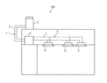
- FIG. 1 is a schematic view showing an installation example of an air conditioner according to an embodiment.
- the air conditioner 100 includes a refrigerant circuit 1 and a heat medium circuit 2.
- the refrigerant circuit 1 is provided with an outdoor unit 3.
- the heat medium circuit 2 is provided with a plurality of indoor units 4. Further, the refrigerant circuit 1 and the heat medium circuit 2 are provided with a relay unit 5.
- the outdoor unit 3 and the relay unit 5 are connected by a refrigerant pipe 6. Further, the relay unit 5 and each of the plurality of indoor units 4 are connected by a heat medium pipe 7.
- the air conditioner 100 may include a plurality of relay units 5.
- the outdoor unit 3 is connected to each of the plurality of relay units 5 by the refrigerant pipe 6, and each relay unit 5 is connected to each of one or more indoor units 4.
- Refrigerant circulates in the refrigerant circuit 1.
- the refrigerant is, for example, a single refrigerant such as R22 or R134a, a pseudo-azeotropic mixed refrigerant such as R410A or R404A, or a non-azeotropic mixed refrigerant such as R407C.
- the refrigerant may be, for example, a refrigerant having a relatively small global warming potential such as R1234yf containing a double bond in the chemical formula, or a mixture thereof, or a natural refrigerant such as CO 2 or propane.
- the refrigerant is cooled or heated in the outdoor unit 3.
- a heat medium circulates in the heat medium circuit 2.
- the heat medium is a heat medium that does not change its state within the utilization temperature range, and is, for example, water, brine, a mixed solution of brine and water, or a mixed solution of an additive having a high anticorrosion effect and water.
- the heat medium exchanges heat with the refrigerant cooled or heated in the outdoor unit 3 in the relay unit 5. After exchanging heat with the refrigerant, the heat medium exchanges heat with the air in the room, which is the space to be air-conditioned, in the indoor unit 4. As a result, the room is air-conditioned.
- the outdoor unit 3 on the side that generates heat functions as a heat source machine, and the refrigerant circuit 1 in which the refrigerant that supplies the heat to the heat medium circulates through the relay unit 5 functions as a heat source facility.
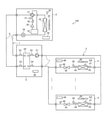
- FIG. 2 is a diagram showing an example of the configuration of the air conditioner according to the embodiment.
- the outdoor unit 3 has a compressor 30, a flow path switching device 31, a heat source side blower 32, a heat source side heat exchanger 33, a throttle device 34, and an accumulator 35 in the housing.
- the accumulator 35, the compressor 30, the flow path switching device 31, the heat source side heat exchanger 33, and the throttle device 34 are connected by a refrigerant pipe 6.
- the compressor 30 sucks in the refrigerant, compresses it, and discharges it in a high temperature and high pressure state.
- the compressor 30 may be, for example, one whose capacity can be controlled.
- the flow path switching device 31 is a device that switches the flow path of the refrigerant depending on whether the air conditioning device 100 executes a cooling operation or a heating operation.
- the solid line portion in the flow path switching device 31 indicates the flow path of the refrigerant during the cooling operation
- the broken line portion indicates the flow path of the refrigerant during the heating operation.
- the heat source side blower 32 guides the outdoor air to the heat source side heat exchanger 33.
- the heat source side heat exchanger 33 causes heat exchange between the outdoor air supplied by the heat source side blower 32 and the refrigerant.
- the heat source side heat exchanger 33 functions as a condenser or a radiator during the cooling operation, and causes the refrigerant to dissipate heat.
- the heat source side heat exchanger 33 functions as an evaporator during the heating operation and causes the refrigerant to absorb heat.
- the air after heat exchange in the heat source side heat exchanger 33 is sent out to the outside by the heat source side blower 32.
- the throttle device 34 includes a pressure reducing valve, an expansion valve, etc., and reduces the pressure of the refrigerant to expand it.
- the throttle device 34 may include, for example, an electronic expansion valve, the opening degree can be controlled to an arbitrary size, and the flow rate of the refrigerant can be arbitrarily adjusted.
- the diaphragm device 34 may be installed in the relay unit 5 instead of the outdoor unit 3, or may be installed in each of the outdoor unit 3 and the relay unit 5.
- the accumulator 35 is provided on the suction side of the refrigerant of the compressor 30 in the outdoor unit 3.
- the accumulator 35 stores, for example, the surplus refrigerant generated by the difference in the amount of the refrigerant used in the heating operation and the cooling operation, or the surplus refrigerant generated in the transitional period when the operating state of the air conditioner 100 changes. ..
- the accumulator 35 does not have to be installed in the outdoor unit 3.
- the indoor unit 4 has an indoor side blower 40, an indoor heat exchanger 41, and a flow rate adjusting device 42 in a housing.
- the indoor heat exchanger 41 and the flow rate adjusting device 42 are connected by a heat medium pipe 7.
- the indoor blower 40 guides the indoor air to the indoor heat exchanger 41 and generates an air flow for returning the air to the indoor.
- the indoor heat exchanger 41 includes a heat transfer tube and fins, and a heat medium passes through the heat transfer tube.
- the indoor heat exchanger 41 exchanges heat between the indoor air supplied by the indoor blower 40 and the heat medium passing through the heat transfer tube.
- the air is cooled.
- the room is air-conditioned by cooling.
- the temperature of the heat medium passing through the heat transfer tube is higher than the temperature of the air, the air is heated. By sending the heated air into the room, the room is air-conditioned by heating.
- the flow rate adjusting device 42 is configured by using, for example, a two-way valve capable of controlling the opening degree of the valve.
- the flow rate adjusting device 42 controls the flow rate of the heat medium flowing through the indoor heat exchanger 41 by adjusting the opening degree.
- the state in which the opening degree of the flow rate adjusting device 42 is not 0 and the flow rate adjusting device 42 distributes the heat medium may be described as an open state.
- a state in which the opening degree of the flow rate adjusting device 42 is 0 and the flow rate adjusting device 42 does not allow the heat medium to flow may be described as a closed state or a fully closed state.
- the flow rate adjusting device 42 adjusts the opening degree according to an instruction from the indoor control device 48 described later.
- the flow rate adjusting device 42 is an indoor heat exchanger according to an instruction from the indoor control device 48 based on the temperature of the heat medium flowing into the indoor heat exchanger 41 and the temperature of the heat medium flowing out of the indoor heat exchanger 41. Adjust the amount of heat medium to pass through 41. As a result, in the indoor heat exchanger 41, heat exchange can be performed by the amount of heat according to the heat load in the room.
- the flow rate adjusting device 42 is installed in the heat medium pipe 7 where the heat medium flows out from the indoor heat exchanger 41, but the heat medium pipe on the side where the heat medium flows into the indoor heat exchanger 41. It may be installed in 7. Regardless of whether the flow rate adjusting device 42 is provided on either the outflow side of the heat medium from the indoor heat exchanger 41 or the inflow side of the heat medium into the indoor heat exchanger 41, the heat medium is generated by the pump 51 described later. Since it is pressurized, the flow rate of the heat medium flowing out of the indoor unit 4 and the flow rate of the heat medium flowing into the indoor heat exchanger 41 can be adjusted.
- the flow rate adjusting device 42 provides indoor heat when there is no need for heat exchange in the indoor heat exchanger 41, such as when the air conditioner 100 or the indoor unit 4 has stopped operating or is in a thermo-off state.
- the valve may be fully closed so that the heat medium does not flow into the exchanger 41.
- the flow rate adjusting device 42 in the embodiment is in a fully closed state unless the indoor control device 48 instructs to perform the air conditioning operation when the indoor unit 4 does not perform the air conditioning operation or when the indoor unit 4 is in the thermo-off state. And.
- the relay unit 5 has a relay heat exchanger 50 and a pump 51.
- the relay heat exchanger 50 causes heat exchange between the refrigerant and the heat medium.
- the relay heat exchanger 50 heats the heat medium when the air conditioner 100 is in the heating operation.
- the relay heat exchanger 50 functions as a condenser or a radiator, and the refrigerant dissipates heat to the heat medium.
- the relay heat exchanger 50 the heat medium is cooled when the air conditioner 100 is in the cooling operation.
- the relay heat exchanger 50 functions as an evaporator, and the refrigerant absorbs heat from the heat medium.
- the pump 51 sucks the heat medium flowing out from the relay heat exchanger 50, pressurizes it, and sends it to the heat medium pipe 7.
- the heat medium circulates in the heat medium circuit 2 by pressurization by the pump 51.
- the pump 51 is an example of a circulation device that circulates a heat medium in the heat medium circuit 2.
- the compressor 30 sucks in the refrigerant, compresses it, and discharges it in a high temperature and high pressure state.
- the discharged refrigerant flows into the heat source side heat exchanger 33 via the flow path switching device 31.
- the heat source side heat exchanger 33 causes heat exchange between the inflowing refrigerant and the air supplied by the heat source side blower 32, and condenses and liquefies the refrigerant.
- the condensed refrigerant passes through the drawing device 34.
- the throttle device 34 depressurizes the passing refrigerant.
- the decompressed refrigerant flows out of the outdoor unit 3, passes through the refrigerant pipe 6, and flows into the relay heat exchanger 50 of the relay unit 5.
- the relay heat exchanger 50 exchanges heat between the inflowing heat source side refrigerant and the heat medium.
- the heat medium flows out of the indoor unit 4 and flows into the relay heat exchanger 50 in the relay unit 5.
- the refrigerant absorbs heat from the heat medium and evaporates, and the heat medium dissipates heat to the refrigerant and is cooled.
- the refrigerant flowing out of the relay heat exchanger 50 flows out of the relay unit 5, passes through the refrigerant pipe 6, and flows into the outdoor unit 3.
- the refrigerant that has flowed into the outdoor unit 3 passes through the flow path switching device 31 again and is sucked into the compressor 30.
- the heat medium flowing out of the relay heat exchanger 50 is pressurized by the pump 51, flows out of the relay unit 5, passes through the heat medium pipe 7, and flows into the indoor unit 4.
- the heat medium that has flowed into the indoor unit 4 flows into the indoor heat exchanger 41.
- the indoor heat exchanger 41 exchanges heat between the inflowing heat medium and the air supplied by the indoor blower 40.
- the heat medium absorbs heat from the air, and the air is cooled.
- the air is sent out into the room by the indoor blower 40.
- the heat medium flowing out of the indoor heat exchanger 41 flows out of the indoor unit 4 via the flow rate adjusting device 42 in the open state, passes through the heat medium pipe 7, and flows into the relay heat exchanger 50 of the relay unit 5 again. do.
- the compressor 30 sucks in the refrigerant, compresses it, and discharges it in a high temperature and high pressure state.
- the discharged refrigerant flows out from the outdoor unit 3 via the flow path switching device 31, passes through the refrigerant pipe 6, and flows into the relay heat exchanger 50 of the relay unit 5.
- the relay heat exchanger 50 causes heat exchange between the passing refrigerant and the heat medium.
- the refrigerant dissipates heat to the heat medium, condenses and liquefies. Then, the heat medium absorbs heat from the refrigerant and is heated.
- the heat source side heat exchanger 33 exchanges heat between the inflowing refrigerant and the air supplied by the heat source side blower 32, and evaporates the refrigerant to gasify it.
- the evaporative gasified refrigerant passes through the flow path switching device 31 and is sucked into the compressor 30.
- the heat medium flowing out from the relay heat exchanger 50 flows out from the relay unit 5, passes through the heat medium piping 7, and flows into the indoor unit 4.
- the heat medium flowing into the indoor unit 4 exchanges heat with the air supplied by the indoor blower 40 in the indoor heat exchanger 41.
- the heat medium dissipates heat to the air, and the air is heated.
- the air is sent out into the room by the indoor blower 40.
- the heat medium flowing out of the indoor heat exchanger 41 flows out of the indoor unit 4 via the flow rate adjusting device 42 in the open state, passes through the heat medium pipe 7, and flows into the relay heat exchanger 50 of the relay unit 5 again. do.
- the air conditioner 100 includes various sensors that detect physical quantities and various control devices that perform control using the detected physical quantities.
- the outdoor unit 3 has a discharge temperature sensor 36, a discharge pressure sensor 37, an outdoor temperature sensor 38, and an outdoor control device 39.
- the relay unit 5 includes a first refrigerant temperature sensor 52, a second refrigerant temperature sensor 53, a heat medium inflow side temperature sensor 54, a heat medium outflow side temperature sensor 55, and a relay control device 56.
- the indoor unit 4 includes an indoor inflow side temperature sensor 43, an indoor outflow side temperature sensor 44, an indoor inflow side pressure sensor 45, an indoor outflow side pressure sensor 46, an indoor temperature sensor 47, and an indoor control device 48.
- the discharge temperature sensor 36 in the outdoor unit 3 is provided in the refrigerant pipe 6 on the discharge side of the refrigerant from the compressor 30, and detects the temperature of the refrigerant discharged by the compressor 30. Then, the discharge temperature sensor 36 outputs a discharge temperature detection signal indicating the temperature of the detected refrigerant to the outdoor control device 39.
- the discharge temperature sensor 36 in the embodiment shall include a thermistor.
- the outdoor temperature sensor 38, the first refrigerant temperature sensor 52, the second refrigerant temperature sensor 53, the heat medium inflow side temperature sensor 54, and the heat medium outflow side temperature sensor 55 in the embodiments also include a thermista, respectively. It shall be a waste.
- the indoor inflow side temperature sensor 43, the indoor outflow side temperature sensor 44, and the indoor temperature sensor 47 in the embodiment also include the thermistor.
- the discharge pressure sensor 37 is provided in the refrigerant pipe 6 on the discharge side of the refrigerant from the compressor 30, and detects the pressure of the refrigerant discharged by the compressor 30. Then, the discharge pressure sensor 37 outputs a discharge pressure detection signal indicating the detected pressure of the refrigerant to the outdoor control device 39.
- the outdoor temperature sensor 38 is provided at a position in the outdoor unit 3 where air flows into the heat source side heat exchanger 33, and detects the outdoor temperature, which is the temperature of the surrounding environment of the outdoor unit 3. Then, the outdoor temperature sensor 38 outputs an outdoor temperature detection signal indicating the detected outdoor temperature to the outdoor control device 39.
- the outdoor control device 39 controls components such as the compressor 30, the flow path switching device 31, and the heat source side blower 32 included in the outdoor unit 3. The details of the outdoor control device 39 will be described later.
- the first refrigerant temperature sensor 52 in the relay unit 5 is installed in the refrigerant pipe 6 on the side where the refrigerant flows into the relay heat exchanger 50 during the cooling operation.
- the second refrigerant temperature sensor 53 is installed in the refrigerant pipe 6 on the side where the refrigerant flows into the relay heat exchanger 50 during the heating operation.
- the first refrigerant temperature sensor 52 and the second refrigerant temperature sensor 53 detect the temperature of the refrigerant flowing into the relay heat exchanger 50 or the temperature of the refrigerant flowing out of the relay heat exchanger 50. Then, the first refrigerant temperature sensor 52 and the second refrigerant temperature sensor 53 output a refrigerant temperature detection signal indicating the detected refrigerant temperature to the relay control device 56.
- the heat medium inflow side temperature sensor 54 is provided in the heat medium pipe 7 on the side where the heat medium flows into the relay heat exchanger 50, and detects the temperature of the heat medium flowing into the relay heat exchanger 50. Then, the heat medium inflow side temperature sensor 54 outputs an inflow side heat medium temperature detection signal indicating the detected temperature of the heat medium to the relay control device 56.
- the heat medium outflow side temperature sensor 55 is provided in the heat medium pipe 7 where the heat medium flows out from the relay heat exchanger 50, and detects the temperature of the heat medium flowing out from the relay heat exchanger 50. Then, the heat medium outflow side temperature sensor 55 outputs an outflow side heat medium temperature detection signal indicating the detected temperature of the heat medium to the relay control device 56.
- the relay control device 56 controls the pump 51 and the like. The details of the relay control device 56 will be described later.
- the relay unit 5 may have a sensor such as a pressure sensor that detects the pressure of the heat medium or the refrigerant, or a flow sensor that detects the flow rate of the heat medium or the refrigerant.
- a sensor such as a pressure sensor that detects the pressure of the heat medium or the refrigerant, or a flow sensor that detects the flow rate of the heat medium or the refrigerant.
- the indoor inflow side temperature sensor 43 in the indoor unit 4 is provided in the heat medium pipe 7 on the side where the heat medium flows into the indoor heat exchanger 41, and detects the temperature of the heat medium flowing into the indoor heat exchanger 41. Then, the indoor inflow side temperature sensor 43 outputs an indoor inflow side temperature detection signal indicating the detected temperature of the heat medium to the indoor control device 48.
- the indoor outflow side temperature sensor 44 is provided in the heat medium pipe 7 where the heat medium flows out from the indoor heat exchanger 41, and detects the temperature of the heat medium flowing out from the indoor heat exchanger 41. Then, the indoor outflow side temperature sensor 44 outputs an indoor outflow side temperature detection signal indicating the temperature of the detected heat medium to the indoor control device 48.
- the indoor inflow side pressure sensor 45 is provided in the heat medium pipe 7 on the side where the heat medium flows into the flow rate adjusting device 42, and detects the pressure of the heat medium flowing into the flow rate adjusting device 42. Then, the indoor inflow side pressure sensor 45 outputs an indoor inflow side pressure detection signal indicating the detected pressure of the heat medium to the indoor control device 48.
- the indoor outflow side pressure sensor 46 is provided in the heat medium pipe 7 where the heat medium flows out from the flow rate adjusting device 42, and detects the pressure of the heat medium flowing out from the flow rate adjusting device 42. Then, the indoor outflow side pressure sensor 46 outputs an indoor outflow side pressure detection signal indicating the detected pressure of the heat medium to the indoor control device 48.
- the indoor unit 4 When a pressure sensor for detecting the pressure of the heat medium circulating in the heat medium circuit 2 is included in the indoor unit 4 in addition to the indoor unit 4, such as the relay unit 5, the indoor unit 4 has an indoor inflow side. At least one of the pressure sensor 45 and the indoor outflow side pressure sensor 46 may not be included. Further, in the indoor unit 4, instead of at least one of the indoor inflow side pressure sensor 45 and the indoor outflow side pressure sensor 46, or at least one of the indoor inflow side pressure sensor 45 and the indoor outflow side pressure sensor 46. In addition, a flow rate detecting device for detecting the flow rate of the heat medium may be included.
- the indoor temperature sensor 47 is provided on the side where air flows into the indoor heat exchanger 41. Then, the indoor temperature sensor 47 detects the suction temperature, which is the temperature of the air flowing into the indoor heat exchanger 41, by the flow of air driven by the indoor blower 40. The suction temperature can be assumed as the temperature of the air in the room to be air-conditioned. The indoor temperature sensor 47 outputs a suction temperature detection signal indicating the suction temperature to the indoor control device 48.
- the indoor control device 48 controls components such as the indoor blower 40 and the flow rate adjusting device 42 included in the indoor unit 4.
- the indoor control device 48 uses the indoor inflow side temperature sensor 43 and the indoor outflow side temperature sensor 44 to determine the amount of heat from the heat medium to the air or the amount of heat from the air to the heat medium due to heat exchange in the indoor heat exchanger 41. Obtained by calculation using the detection result.
- the indoor unit 4 may have a heat quantity detecting device capable of detecting the heat quantity by heat exchange between the indoor air and the heat medium. Then, the indoor control device 48 may acquire the detection information indicating the calorific value from the calorific value detecting device.
- each of the outdoor control device 39, the indoor control device 48, and the relay control device 56 can communicate with each other by wire or wirelessly.
- Each control device of the outdoor control device 39, the indoor control device 48, and the relay control device 56 responds to a physical quantity indicated by a signal acquired from the above-mentioned various sensors, an instruction indicated by a signal received from another control device, or the like. , Control the components to be controlled.
- the outdoor control device 39 and the relay control device 56 receive a setting instruction or the like input to the indoor unit 4 via a remote controller (not shown) from the indoor control device 48, and are controlled according to the setting instruction. Controls the components of.
- Each of the outdoor control device 39, the indoor control device 48, and the relay control device 56 includes a processor such as a CPU (Central Processing Unit) or an MPU (Micro Processing Unit), and a ROM (Read Only Memory) or a RAM (Random Access Memory). It can be configured by using a memory such as, a communication interface circuit, an input / output interface circuit, and the like.
- a processor such as a CPU (Central Processing Unit) or an MPU (Micro Processing Unit), and a ROM (Read Only Memory) or a RAM (Random Access Memory). It can be configured by using a memory such as, a communication interface circuit, an input / output interface circuit, and the like.
- Each communication function of the outdoor control device 39, the indoor control device 48, and the relay control device 56 can be realized by the communication interface circuit.
- the functions of acquiring the detection signals from various sensors of each of the outdoor control device 39, the indoor control device 48, and the relay control device 56 can be realized by the input / output interface circuit.
- each control function of the outdoor control device 39, the indoor control device 48, and the relay control device 56 the processor executes an application such as a device driver stored in the memory, and the processor executes an application such as a device driver, and the processor executes an application such as a device driver and uses the input / output interface circuit. It can be realized by transmitting a control signal for controlling the control target to the control target.
- the arithmetic function or determination function of each of the outdoor control device 39, the indoor control device 48, and the relay control device 56 can be realized by the processor executing various programs stored in the memory.
- each of the outdoor control device 39, the indoor control device 48, and the relay control device 56 may be used as dedicated hardware in whole or in part.
- each of the outdoor control device 39, the indoor control device 48, and the relay control device 56 may be configured by using a PLC (Programmable Logic Controller) such as an FPGA (Field-Programmable Gate Array). Further, the control functions of the outdoor control device 39, the indoor control device 48, and the relay control device 56 may be realized by using a driver circuit.
- PLC Programmable Logic Controller
- FPGA Field-Programmable Gate Array
- the indoor control device 48 transmits the acquired signal indicating the amount of heat to the relay control device 56.
- the indoor control device 48 transmits a signal indicating a physical quantity detected by the sensor in the indoor unit 4, such as the indoor inflow side temperature sensor 43 or the indoor outflow side temperature sensor 44, to the relay control device 56.
- the indoor control device 48 may transmit data regarding the characteristics of the equipment of the indoor unit 4, such as the heat exchange capacity of the indoor heat exchanger 41, to the relay control device 56.
- the relay heat exchanger may not be supplied with a heat medium having a sufficient flow rate. If the flow rate of the heat medium to the relay unit cannot be secured during the cooling operation, the heat medium in the relay heat exchanger is excessively cooled by the refrigerant cooled in the outdoor unit, and the heat medium freezes. There is a risk.
- the flow velocity of the heat medium can be increased by pressurization by the pump.
- the oxide film protecting the heat medium pipe may be peeled off. The peeling may cause erosion in which the metal of the heat medium piping is corroded.
- erosion is likely to occur.
- the flow velocity at which erosion occurs differs depending on the type of metal used as the material for the heat medium piping.
- Some conventional air conditioners have an outdoor unit with a function to prevent freezing as described above. However, if the outdoor unit repeats the control based on the function and the control for the cooling operation, the operation may become unstable.
- FIG. 3 is a flowchart illustrating the antifreezing process by the air conditioner according to the embodiment.
- a part of the indoor units 4 out of the plurality of indoor units 4 performs a cooling operation will be described as an example. That is, it is assumed that the part of the indoor units 4 is activated and performs the cooling operation, and the other indoor units 4 do not perform the cooling operation or the heating operation.
- the part of the indoor unit 4 that performs the cooling operation is described as the indoor unit 4 that operates or the indoor unit 4 that is in the operating state, and the indoor unit 4 that does not perform the cooling operation or the heating operation is stopped. It may be described as the indoor unit 4 in a state.
- step S1 the indoor control device 48 of the indoor unit 4 to be operated opens the flow rate adjusting device 42 in order to circulate the heat medium in response to the instruction to start the cooling operation input via the remote controller or the like. Put it in a state. Further, the indoor control device 48 operates the indoor blower 40 and transmits an operation signal instructing the start of the cooling operation to the relay control device 56. In step S2, the relay control device 56 that has received the operation signal operates the pump 51.
- step S3 the relay control device 56 acquires the flow rate of the heat medium flowing through the relay heat exchanger 50.
- the flow rate is obtained from, for example, the differential pressure of the pressure detected by each of the indoor inflow side pressure sensor 45 and the indoor outflow side pressure sensor 46 in the indoor unit 4 and the Cv value by using, for example, the following equation. May be good.
- Q 45.58 ⁇ Cv ⁇ ( ⁇ P / G) 1/2
- Q, Cv, ⁇ P, and G in the formula are the flow rate of the heat medium [US gal / min], the Cv value of the flow path of the heat medium [-], the differential pressure [kPa], and the heat medium, respectively.
- the Cv value is about 15.5 [, which flows through the flow rate adjusting device 42 in a unit time when the differential pressure is 6.895 [kPa] when the flow rate adjusting device 42 has a specific opening degree. It is defined as the value of the flow rate [US gal / min] of water at the temperature of [° C.].
- the Cv value is a value related to the opening degree of the flow rate adjusting device 42, and since the opening degree changes depending on the heat quantity, the Cv value is a value related to the heat quantity.
- the amount of heat is the amount of heat acquired by the heat medium from the air or the amount of heat given to the air by the heat medium by heat exchange in the indoor heat exchanger 41, and is the amount of heat given to the air by the heat medium, and is the indoor inflow side temperature sensor 43 and the indoor outflow side. It is calculated by the indoor control device 48 from each detection result by the temperature sensor 44.
- the relay control device 56 calculates the Cv value using the amount of heat received from the indoor control device 48. Further, the relay control device 56 calculates the differential pressure ⁇ P from the detection results of each of the indoor inflow side pressure sensor 45 and the indoor outflow side pressure sensor 46 received from the indoor control device 48. In addition, the relay control device 56 acquires each detection result by the indoor inflow side temperature sensor 43 and the indoor outflow side temperature sensor 44 from the indoor control device 48 instead of the above heat amount, and uses each of the detection results to obtain a Cv value. It may be calculated. Alternatively, the relay control device 56 may acquire a signal indicating the opening degree of the flow rate adjusting device 42 from the indoor control device 48 and calculate the Cv value using the opening degree.
- the relay control device 56 controls each of the plurality of indoor units 4 with a signal indicating the detection results of the various sensors for calculating the differential pressure ⁇ P and the Cv value before step S3, such as step S1. It is assumed that the signal is received from the device 48. Then, the relay control device 56 calculates the flow rate Q of the heat medium flowing from each indoor unit 4 to the relay heat exchanger 50 by using the above equation or the like. Then, the relay control device 56 calculates the total flow rate Q from each indoor unit 4 as the total flow rate of the heat medium to the relay heat exchanger 50. In the following, it is assumed that the total flow rate of the heat medium from each of the plurality of indoor units 4 to the relay heat exchanger 50 is also shown using Q.
- the flow rate Q of the heat medium may be acquired by a flow rate sensor provided in the relay unit 5.
- the flow rate Q may be acquired by using the rotation speed of the motor of the pump 51 and the command value from the relay control device 56 to the motor.
- step S4 the relay control device 56 determines whether or not the flow rate Q of the heat medium acquired in step S3 is equal to or greater than the minimum flow rate Qmin.
- the minimum flow rate Qmin is the minimum flow rate of the heat medium required to prevent the heat medium from freezing, for example, when the outdoor unit 3 is started.
- the minimum flow rate Qmin is determined by using the freezing yield strength of the relay heat exchanger 50 and the lowering temperature of the refrigerant when the outdoor unit 3 is started, and is stored in the relay control device 56.
- the freezing proof stress of the relay heat exchanger 50 is determined from the performance or specifications of the relay heat exchanger 50. Further, the lowering temperature of the refrigerant at the time of starting the outdoor unit 3, which is affected by the outside air temperature, is determined by the test.
- step S4 When the flow rate Q is equal to or greater than the minimum flow rate Qmin (step S4: YES), the relay control device 56 shifts the process to step S16.
- step S5 the relay control device 56 measures the temperature between the set temperature Tm in the indoor unit 4 in the operating state and the temperature Tw of the heat medium. It is determined whether or not the difference ⁇ T is equal to or greater than the temperature difference threshold ⁇ Ts.
- the temperature difference ⁇ T is a temperature difference based on the temperature Tw of the heat medium, and is the temperature obtained by subtracting the temperature Tw of the heat medium from the set temperature Tm.
- the set temperature Tm is a temperature set via a remote controller or the like when the indoor unit 4 to be operated is activated, and is included in the information indicated by the operation signal received by the relay control device 56 in step S1. ..
- the temperature Tw of the heat medium is the temperature detected by the indoor inflow side temperature sensor 43, the indoor outflow side temperature sensor 44, the heat medium inflow side temperature sensor 54, or the heat medium outflow side temperature sensor 55.
- the relay control device 56 sets the relay control device 56 during the process of step S5.
- the temperature Tw is received from the indoor control device 48.
- the temperature difference threshold value ⁇ Ts is the temperature difference between the set temperature Tm and the temperature Tw of the heat medium, which is the minimum required for the indoor unit 4 to cool the air to the set temperature Tm, and is determined in advance by a test or the like. Has been done.
- the temperature difference threshold value ⁇ Ts may be flexibly set according to the installation environment of the air conditioner 100 and the like.
- step S5 YES
- the relay control device 56 does not transmit the operation signal to the outdoor control device 39 in step S6, and operates the pump 51.
- the outdoor unit 3 does not operate, but the heat medium circulates in the heat medium circuit 2, and the heat medium flows into the indoor unit 4 in the operating state. Then, the indoor unit 4 exchanges heat between the heat medium and the air to cool the air.
- the relay control device 56 returns the process to step S5.
- the relay control device 56 may move the process to step S7 or step S16.
- step S5 NO
- the relay control device 56 processes the relay unit 5 in step S7.
- step S7 the relay control device 56 transmits a first open instruction signal instructing the indoor control device 48 of the indoor unit 4 in the stopped state to open the flow rate adjusting device 42.
- the indoor control device 48 opens the flow rate adjusting device 42 and secures a flow path for the heat medium.
- the flow path resistance of the heat medium is reduced, and the pressure loss is reduced. Therefore, the flow rate Q of the heat medium to the relay heat exchanger 50 increases.
- each flow rate adjusting device is such that the ratio of the capacity of each of the plurality of indoor units 4 is equal to the ratio of the Cv value of each flow rate adjusting device 42 of the plurality of indoor units 4. This is for controlling the opening degree of 42.
- the indoor control device 48 keeps the flow rate adjusting device 42 in the closed state. It is also good.
- the room temperature threshold Tas is stored in advance in the room control device 48.
- the indoor temperature threshold Tas is a predetermined time when a heat medium having a temperature lower than the minimum configurable temperature Tmmin of the indoor unit 4 by the temperature difference threshold ⁇ Ts flows through the indoor unit 4 by the rated flow rate of the indoor unit 4. , The upper limit of the room temperature at which dew dripping does not occur.
- the rated flow rate of the indoor unit 4 is determined by the capacity of the indoor unit 4.
- step S8 the relay control device 56 opens the flow rate adjusting device 42 of the indoor unit 4 in the stopped state, so that the flow rate Q of the heat medium flowing into the relay heat exchanger 50 becomes the minimum flow rate Qmin or more.
- the flow rate Q is calculated using the above-mentioned signal indicating the pressure, the signal indicating the amount of heat or the temperature, or the like from the indoor control device 48, these signals open the flow rate adjusting device 42. It is assumed that the relay control device 56 receives the signal from the indoor control device 48 after the state is set.
- step S8 When the flow rate Q of the heat medium flowing into the relay heat exchanger 50 is the minimum flow rate Qmin or more (step S8: YES), the relay control device 56 shifts the process to step S16.
- the relay control device 56 in step S9 is the indoor control device 48 of the indoor unit 4 in the stopped state.
- the second open instruction signal is transmitted to.
- the second open instruction signal is a signal instructing the opening degree of the flow rate adjusting device 42 to be increased by ⁇ Cv. It should be noted that ⁇ Cv is a predetermined minute opening degree.
- the first open instruction signal and the second open instruction signal are examples of open instruction signals instructing the opening degree of the flow rate adjusting device 42 to be increased, respectively.
- the indoor control device 48 that has received the second open instruction signal determines in step S10 whether or not the opening degree of the flow rate adjusting device 42 is the maximum.
- the indoor control device 48 tells the relay control device 56 that the opening degree of the flow rate adjusting device 42 is already the maximum in step S11. The indicated maximum opening signal is transmitted.
- the relay control device 56 that has received the maximum opening signal transmits a stop signal instructing the outdoor control device 39 and the indoor control device 48 to stop the cooling operation in step S12.
- the outdoor control device 39 stops the operation of the outdoor unit 3.
- the indoor control device 48 that has received the stop signal stops the operation of the indoor unit 4.
- the relay control device 56 may omit the transmission of the stop signal to the indoor control device 48, which is the transmission source of the maximum opening signal. In this case, the indoor control device 48 stops the operation of the indoor unit 4 based on the determination result in step S10.
- the air conditioner 100 ends the antifreeze process.
- step S10 NO
- the indoor control device 48 sets the opening degree of the flow rate adjusting device 42 to ⁇ Cv in step S13. Just make it bigger.
- the indoor control device 48 closes the flow rate adjusting device 42. May be maintained.
- step S14 the relay control device 56 determines whether the flow rate Q of the heat medium flowing into the relay heat exchanger 50 is equal to or higher than the minimum flow rate Qmin.
- the relay control device 56 shifts the process to step S16.
- step S15 When the flow rate Q of the heat medium flowing into the relay heat exchanger 50 is less than the minimum flow rate Qmin (step S14: NO), the relay control device 56 in step S15 transmits a second open instruction signal in step S9. It is determined from the above whether or not the predetermined waiting time ⁇ t1 has elapsed. While the standby time ⁇ t1 does not elapse (step S15: NO), the relay control device 56 keeps the process in step S15. When the waiting time ⁇ t1 has elapsed (step S15: YES), the relay control device 56 returns the process to step S9.
- step S16 the relay control device 56 transmits an operation signal instructing the start of the cooling operation to the outdoor control device 39.
- the outdoor control device 39 that has received the operation signal operates the compressor 30.
- step S17 the relay control device 56 determines whether or not the refrigerant stabilization time ⁇ t2 has elapsed since the operation signal was transmitted to the outdoor control device 39.
- the refrigerant stabilization time ⁇ t2 is the time until the temperature of the refrigerant stabilizes, and is, for example, the initial acceleration time at the time of starting the compressor 30 under the control of the outdoor control device 39.
- the speed increase time refers to the time from when the compressor 30 starts operating until the rotation speed becomes constant.
- the refrigerant stabilization time is determined by the control content of the outdoor control device 39 and the like. While the refrigerant stabilization time ⁇ t2 does not elapse (step S17: NO), the relay control device 56 keeps the process in step S17.
- step S18 the relay control device 56 instructs the indoor control device 48 in the indoor unit 4 in the stopped state to close the flow rate adjusting device 42. Send an instruction signal.
- the outdoor unit 3, the relay unit 5, and the indoor unit 4 in the operating state shift to the normal cooling operation. Then, the air conditioner 100 ends the antifreezing process.
- the air conditioner 100 may perform the following processing instead of the processing in steps S9 to S13.
- the relay control device 56 receives information indicating the opening degree of the flow rate adjusting device 42 from the indoor control device 48 of the indoor unit 4 in the stopped state, for example, before returning the processing to step S7, step S8, or step S9. It is received at the timing of step S13 or the like. Then, the relay control device 56 determines whether the opening degree of the flow rate adjusting device 42 is the maximum, and if the opening degree is the maximum, the relay control device 56 transmits a stop signal to the outdoor control device 39 and the indoor control device 48. The relay control device 56 transmits an open instruction signal to the indoor control device 48 if the opening degree is not the maximum. Then, the indoor control device 48 that has received the open instruction signal increases the opening degree by ⁇ Cv.
- the air conditioner 100 includes a refrigerant circuit 1 in which a refrigerant circulates and a heat medium circuit 2 in which a heat medium circulates.
- the air conditioner 100 includes an outdoor unit 3, a plurality of indoor units 4, and a relay unit 5.
- the outdoor unit 3 is provided in the refrigerant circuit 1 and exchanges heat between the refrigerant and the outdoor air.
- the plurality of indoor units 4 are provided in the heat medium circuit 2 and perform air conditioning by exchanging heat between the heat medium and the indoor air.
- the relay unit 5 is provided in the refrigerant circuit 1 and the heat medium circuit 2, exchanges heat between the refrigerant and the heat medium, and sends the heat medium after the heat exchange with the refrigerant to the plurality of indoor units 4.
- Each of the plurality of indoor units 4 has a flow rate adjusting device 42 and an indoor control device 48.
- the flow rate adjusting device 42 adjusts the flow rate Q of the heat medium flowing out from the indoor unit 4.
- the indoor control device 48 controls the opening degree of the flow rate adjusting device 42.
- the relay unit 5 includes a relay heat exchanger 50, a circulation device, and a relay control device 56.
- the relay heat exchanger 50 exchanges heat between the refrigerant and the heat medium.
- the circulation device circulates the heat medium between each of the plurality of indoor units 4 and the relay heat exchanger 50.
- the relay control device 56 controls the circulation device. Further, in the relay control device 56, when at least one indoor unit 4 out of the plurality of indoor units 4 starts operation, the flow rate Q of the heat medium flowing into the relay heat exchanger 50 from the plurality of indoor units 4 is determined. It is determined whether or not the minimum flow rate is Qmin or more. When the relay control device 56 determines that the flow rate Q is less than the minimum flow rate Qmin, the relay control device 56 opens the flow rate adjusting device 42 to the indoor control device 48 of the indoor unit 4 in the stopped state among the plurality of indoor units 4. Sends an open instruction signal instructing to increase the degree. When the indoor control device 48 receives the open instruction signal, the indoor control device 48 increases the opening degree of the flow rate adjusting device 42 according to the open instruction signal.
- the relay control device 56 determines whether or not the flow rate Q of the heat medium flowing into the relay heat exchanger 50 is equal to or greater than the minimum flow rate Qmin.
- the relay control device 56 transmits an open instruction signal instructing the indoor control device 48 of the indoor unit 4 in the stopped state to increase the opening degree. do.
- the indoor control device 48 that has received the open instruction signal increases the opening degree of the flow rate adjusting device 42.
- the heat medium flows into the relay heat exchanger 50 not only from the indoor unit 4 in the operating state but also from the indoor unit 4 in the stopped state.
- the air conditioner 100 can suppress the freezing of the heat medium in the relay heat exchanger 50. Further, in the air conditioner 100 of the embodiment, the flow rate Q of the heat medium is increased by increasing the opening degree of the flow rate adjusting device 42 of the indoor unit 4 in the stopped state, so that the flow rate Q is secured. No need to install a bypass circuit. Therefore, the cost of the air conditioner 100 can be reduced.
- the relay control device 56 in the embodiment determines whether or not the flow rate Q is the minimum flow rate Qmin or more.
- the relay control device 56 determines that the flow rate Q is less than the minimum flow rate Qmin, the relay control device 56 retransmits the open instruction signal to the indoor control device 48 of the indoor unit 4 in the stopped state.
- the air conditioner 100 can increase the opening degree of the flow rate adjusting device 42 in the indoor unit 4 in the stopped state until the flow rate Q of the heat medium becomes the minimum flow rate Qmin or more. Therefore, the flow rate Q of the heat medium to the relay heat exchanger 50 increases until the minimum flow rate Qmin or more is reached. Therefore, the air conditioner 100 can surely suppress the freezing of the heat medium in the relay heat exchanger 50.
- the first The open instruction signal is transmitted to the indoor control device 48 of the indoor unit 4 in the stopped state.
- the first open instruction signal is a signal instructing the flow rate adjusting device 42 to be in the open state, and is one of the open instruction signals.
- the indoor unit 4 in the stopped state which is the transmission destination of the first open instruction signal, has the flow rate adjusting device 42 in the closed state.
- the indoor control device 48 receives the first open instruction signal, the indoor control device 48 opens the flow rate adjusting device 42 according to the first open instruction signal.
- the air conditioner 100 can open the closed flow rate adjusting device 42 when the flow rate Q of the heat medium is less than the minimum flow rate Qmin. Therefore, the flow path resistance of the heat medium is reduced and the pressure loss is reduced, so that the flow rate Q of the heat medium to the relay heat exchanger 50 is increased. Therefore, the air conditioner 100 can suppress the freezing of the heat medium in the relay heat exchanger 50.
- the relay control device 56 when there are two or more indoor units 4 in a stopped state in which the flow rate adjusting device 42 is closed, the following first open instruction signal is sent by 2. It is transmitted to the indoor unit 4 in the stopped state as described above.
- the first open instruction signal is the ratio of the capacity of each of the indoor units 4 in the two or more stopped states to the Cv value of each flow rate adjusting device 42 of the indoor units 4 in the two or more stopped states. It is instructed to control the opening degree of the flow rate adjusting device 42 so that may be equal to. As a result, the required heat medium is distributed to each indoor unit 4 according to the capacity.
- the relay control device 56 in the embodiment determines whether or not the flow rate Q is the minimum flow rate Qmin or more after transmitting the first open instruction signal to the indoor control device 48 of the indoor unit 4 in the stopped state.
- the relay control device 56 informs the indoor control device 48 of the indoor unit 4 that the opening degree of the flow rate adjusting device 42 is only a predetermined opening degree ⁇ Cv.
- a second open instruction signal instructing to increase the volume is transmitted.
- the second open instruction signal is one of the other open instruction signals.
- the air conditioner 100 can further increase the opening degree of the flow rate adjusting device 42 in the indoor unit 4 in the stopped state when the flow rate Q of the heat medium is less than the minimum flow rate Qmin. Therefore, the air conditioner 100 can further increase the flow rate Q of the heat medium to the relay heat exchanger 50. Therefore, the air conditioner 100 can suppress the freezing of the heat medium in the relay heat exchanger 50.
- the relay control device 56 in the embodiment determines whether or not the flow rate Q is the minimum flow rate Qmin or more. Then, when the relay control device 56 determines that the flow rate Q is less than the minimum flow rate Qmin, the relay control device 56 again transmits the second open instruction signal to the indoor control device 48 of the indoor unit 4 in the stopped state.
- the air conditioner 100 can gradually increase the opening degree of the flow rate adjusting device 42 in the indoor unit 4 in the stopped state until the flow rate Q of the heat medium becomes the minimum flow rate Qmin or more. Therefore, the air conditioner 100 can set the flow rate Q of the heat medium to the relay heat exchanger 50 to the minimum flow rate Qmin or more. Therefore, the air conditioner 100 can surely suppress the freezing of the heat medium in the relay heat exchanger 50.
- the minimum flow rate Qmin in the embodiment is determined by using the information indicating the lowering temperature of the refrigerant at the start of the outdoor unit 3 and the performance or specifications of the relay heat exchanger 50. As a result, the minimum flow rate Qmin required to prevent the heat medium from freezing is accurately determined for the refrigerant in the relay heat exchanger 50. Then, the air conditioner 100 determines whether the flow rate Q of the heat medium to the relay heat exchanger 50 is equal to or more than the accurately determined minimum flow rate Qmin, and when the flow rate Q is less than the minimum flow rate Qmin, the air conditioner 100 determines. Increase the opening degree of the flow rate adjusting device 42 of the indoor unit 4 in the stopped state. Therefore, the air conditioner 100 can surely secure the flow rate Q of the heat medium for preventing freezing and suppress the freezing of the heat medium.
- the outdoor unit 3 in the embodiment starts operation when it receives an operation signal instructing operation from the relay control device 56.
- the relay control device 56 determines that the flow rate Q of the heat medium is less than the minimum flow rate Qmin, the relay control device 56 does not transmit an operation signal to the outdoor unit 3.
- the air conditioner 100 can suppress the freezing of the heat medium by the refrigerant in the relay heat exchanger 50.
- the outdoor unit 3 has a function for preventing freezing
- the air conditioner 100 can suppress the repetition of the cooling operation process and the process by the function of the outdoor unit 3. can. Therefore, the air conditioner 100 can be operated stably.
- the outdoor unit 3 in the embodiment has a compressor 30 and an outdoor control device 39.
- the compressor 30 compresses the refrigerant.
- the outdoor control device 39 communicates with the relay control device 56 and operates the compressor 30 in response to an operation signal from the relay control device 56.
- the relay control device 56 determines that the flow rate Q of the heat medium is less than the minimum flow rate Qmin, the relay control device 56 does not transmit the operation signal to the outdoor control device 39.
- the flow rate Q of the heat medium is less than the minimum flow rate Qmin, the cooling of the refrigerant in the outdoor unit 3 and the delivery of the refrigerant to the relay heat exchanger 50 are suppressed.
- the air conditioner 100 can suppress the freezing of the heat medium by the refrigerant in the relay heat exchanger 50. Further, when the outdoor unit 3 has a function for preventing freezing, the air conditioner 100 can suppress the repetition of the cooling operation process and the process by the function of the outdoor unit 3. can. Therefore, the air conditioner 100 can be operated stably.
- the relay control device 56 in the embodiment determines that the flow rate Q of the heat medium is the minimum flow rate Qmin or more, the relay control device 56 transmits an operation signal to the outdoor unit 3.
- the relay control device 56 closes the flow rate adjusting device 42 when a predetermined refrigerant stabilization time ⁇ t2 has elapsed as the time required for the refrigerant temperature to stabilize after transmitting the operation signal.
- a closing instruction signal is transmitted to the indoor control device 48 of the indoor unit 4 in the stopped state.
- the outdoor unit 3 starts operation when the flow rate Q of the heat medium with respect to the refrigerant is sufficient to prevent the heat medium from freezing.
- the relay control device 56 transmits the closing instruction signal to the indoor unit 4 in the stopped state after the refrigerant stabilization time ⁇ t2 elapses after transmitting the operation signal, the stop state is reached after the refrigerant temperature stabilizes.
- the heat medium does not flow from the indoor unit 4 in the room to the relay heat exchanger 50. Therefore, an extra heat medium does not flow to the indoor unit 4 in the stopped state, and the temperature change of the heat medium due to heat exchange in the indoor unit 4 in the stopped state is suppressed. Therefore, during the cooling operation, the inflow of the heat medium whose temperature has risen from the indoor unit 4 in the stopped state to the relay heat exchanger 50 is suppressed. This eliminates the need for the outdoor unit 3 to further cool the refrigerant for cooling the heat medium in the relay heat exchanger 50. Therefore, the air conditioner 100 can suppress the freezing of the heat medium and also realize energy saving.
- the relay control device 56 in the embodiment determines that the flow rate Q of the heat medium is the minimum flow rate Qmin or more, the relay control device 56 transmits an operation signal to the outdoor control device 39.
- the relay control device 56 closes the flow rate adjusting device 42 when a predetermined refrigerant stabilization time ⁇ t2 has elapsed as the time required for the refrigerant temperature to stabilize after transmitting the operation signal.
- a closing instruction signal is transmitted to the indoor control device 48 of the indoor unit 4 in the stopped state.
- the refrigerant stabilization time ⁇ t2 is determined by using the speed increasing time from the start of operation of the compressor 30 until the speed becomes constant.
- the outdoor unit 3 starts operation when the flow rate Q of the heat medium with respect to the refrigerant is sufficient to prevent the heat medium from freezing.
- the relay control device 56 transmits a closing instruction signal to the indoor unit 4 in the stopped state after the elapse of the refrigerant stabilization time ⁇ t2 from the transmission of the operation signal to the constant speed of the compressor 30. Therefore, in a state where the temperature of the refrigerant is stable and the heat medium does not freeze, the heat medium does not flow into the relay heat exchanger 50 from the indoor unit 4 in the stopped state. Therefore, the extra heat medium does not flow to the indoor unit 4 in the stopped state. Therefore, the air conditioner 100 can suppress freezing of the heat medium and reduce unnecessary processing.
- the relay unit 5 in the embodiment further has at least one temperature sensor of the heat medium inflow side temperature sensor 54 and the heat medium outflow side temperature sensor 55.
- the heat medium inflow side temperature sensor 54 detects the temperature of the heat medium flowing into the relay heat exchanger 50.
- the heat medium outflow side temperature sensor 55 detects the temperature of the heat medium that has flowed out from the relay heat exchanger 50.
- the relay control device 56 has the set temperature Tm set in the indoor unit 4 in the operating state among the plurality of indoor units 4 and the temperature sensor. It is determined whether or not the temperature difference ⁇ T with the detected temperature Tw is equal to or greater than the temperature difference threshold ⁇ Ts.
- the relay control device 56 does not transmit an open instruction signal to the indoor control device 48 of the indoor unit 4 in the stopped state while the temperature difference ⁇ T is equal to or greater than the temperature difference threshold value ⁇ Ts.
- the outdoor unit 3 does not operate.
- the air conditioner 100 does not operate the outdoor unit 3 when the temperature Tw of the heat medium is sufficiently low for the cooling operation, and the heat medium is transferred to the indoor unit 4 in the stopped state. Air-condition without distributing. Therefore, the air conditioner 100 can cause the indoor unit 4 in the operating state to perform appropriate air conditioning while suppressing the freezing of the heat medium by the refrigerant. Further, since the air conditioner 100 does not distribute the heat medium to the indoor unit 4 in the stopped state, wasteful processing can be reduced.
- the indoor unit 4 in the embodiment further has at least one temperature sensor of the indoor inflow side temperature sensor 43 and the indoor outflow side temperature sensor 44.
- the indoor inflow side temperature sensor 43 detects the temperature of the heat medium flowing into the indoor heat exchanger 41.
- the indoor outflow side temperature sensor 44 detects the temperature of the heat medium that has flowed out from the indoor heat exchanger 41.
- the relay control device 56 receives a signal indicating the temperature Tw detected by the temperature sensor from the indoor control device 48, and is among the plurality of indoor units 4.
- the relay control device 56 does not transmit an open instruction signal to the indoor control device 48 of the indoor unit 4 in the stopped state while the temperature difference ⁇ T is equal to or greater than the temperature difference threshold value ⁇ Ts.
- the outdoor unit 3 does not operate.
- the air conditioner 100 does not operate the outdoor unit 3 and distributes the heat medium to the indoor unit 4 in the stopped state when the temperature of the heat medium is sufficiently low for the cooling operation. Air-condition without letting.
- the air conditioner 100 can cause the indoor unit 4 in the operating state to perform appropriate air conditioning while suppressing the freezing of the heat medium by the refrigerant. Further, since the air conditioner 100 does not distribute the heat medium to the indoor unit 4 in the stopped state, wasteful processing can be reduced.
- Each of the plurality of indoor units 4 in the embodiment further has an indoor inflow side pressure sensor 45, an indoor outflow side pressure sensor 46, an indoor inflow side temperature sensor 43, and an indoor outflow side temperature sensor 44.
- the indoor inflow side pressure sensor 45 detects the pressure of the heat medium flowing into the flow rate adjusting device 42.
- the indoor outflow side pressure sensor 46 detects the pressure of the heat medium flowing out from the flow rate adjusting device 42.
- the indoor inflow side temperature sensor 43 detects the temperature of the heat medium flowing into the indoor heat exchanger 41.
- the indoor outflow side temperature sensor 44 detects the temperature of the heat medium that has flowed out from the indoor heat exchanger 41.
- the relay control device 56 controls each of the plurality of indoor units 4 by indoor control of each detection result by the indoor inflow side pressure sensor 45, the indoor outflow side pressure sensor 46, the indoor inflow side temperature sensor 43, and the indoor outflow side temperature sensor 44. Receive from device 48.
- the relay control device 56 calculates the flow rate Q of the heat medium using each detection result. As a result, the relay control device 56 can acquire an accurate flow rate Q of the heat medium and can execute an appropriate antifreezing process.
- Each of the plurality of indoor units 4 in the embodiment further has an indoor inflow side pressure sensor 45, an indoor outflow side pressure sensor 46, an indoor inflow side temperature sensor 43, and an indoor outflow side temperature sensor 44.
- the indoor inflow side pressure sensor 45 detects the pressure of the heat medium flowing into the flow rate adjusting device 42.
- the indoor outflow side pressure sensor 46 detects the pressure of the heat medium flowing out from the flow rate adjusting device 42.
- the indoor inflow side temperature sensor 43 detects the temperature of the heat medium flowing into the indoor heat exchanger 41.
- the indoor outflow side temperature sensor 44 detects the temperature of the heat medium that has flowed out from the indoor heat exchanger 41.
- the indoor control device 48 uses the temperature detected by the indoor inflow side temperature sensor 43 and the temperature detected by the indoor outflow side temperature sensor 44 to obtain the amount of heat absorbed or dissipated by the heat medium in the indoor heat exchanger 41. Calculate.
- the indoor control device 48 transmits the amount of heat and the detection results of the indoor inflow side pressure sensor 45 and the indoor outflow side pressure sensor 46 to the relay control device 56.
- the relay control device 56 calculates the flow rate Q of the heat medium using the amount of heat received from each of the plurality of indoor units 4 and each detection result. As a result, the relay control device 56 can acquire an accurate flow rate Q of the heat medium and can execute an appropriate antifreezing process.
Landscapes
- Engineering & Computer Science (AREA)
- Mechanical Engineering (AREA)
- General Engineering & Computer Science (AREA)
- Chemical & Material Sciences (AREA)
- Combustion & Propulsion (AREA)
- Physics & Mathematics (AREA)
- Thermal Sciences (AREA)
- Air Conditioning Control Device (AREA)
- Other Air-Conditioning Systems (AREA)
Abstract
Description
図1は、実施の形態に係る空気調和装置の設置例を示す概略図である。空気調和装置100は、冷媒回路1および熱媒体回路2を備える。冷媒回路1には、室外ユニット3が設けられている。熱媒体回路2には、複数の室内ユニット4が設けられている。また、冷媒回路1と熱媒体回路2には、中継ユニット5が設けられている。室外ユニット3と中継ユニット5とは、冷媒配管6によって接続されている。また、中継ユニット5と、複数の室内ユニット4の各々とは、熱媒体配管7によって接続されている。
Q=45.58×Cv×(ΔP/G)1/2
Claims (15)
- 冷媒が循環する冷媒回路と、
熱媒体が循環する熱媒体回路と、
前記冷媒回路に設けられ、前記冷媒と室外の空気とを熱交換させる室外ユニットと、
前記熱媒体回路に設けられ、前記熱媒体と室内の空気とを熱交換させることにより空調を行う、複数の室内ユニットと、
前記冷媒回路および前記熱媒体回路に設けられ、前記冷媒と前記熱媒体とを熱交換させ、前記冷媒との熱交換後の前記熱媒体を、前記複数の室内ユニットに送り出す中継ユニットと、
を備え、
前記複数の室内ユニットの各々は、
前記複数の室内ユニットの各々から流出する前記熱媒体の流量を調整する流量調整装置と、
前記流量調整装置の開度を制御する室内制御装置と、
を有し、
前記中継ユニットは、
前記冷媒と前記熱媒体とを熱交換させる中継熱交換器と、
前記複数の室内ユニットの各々と前記中継熱交換器との間において前記熱媒体を循環させる循環装置と、
前記循環装置を制御する中継制御装置と、
を有し、
前記中継制御装置は、
前記複数の室内ユニットのうち少なくとも1つの前記室内ユニットが運転を開始した場合において、前記複数の室内ユニットから前記中継熱交換器に流入する前記熱媒体の流量が、予め定められた最低流量以上であるか否かを判定し、前記流量が前記最低流量未満であると判定した場合には、前記複数の室内ユニットのうち、停止状態にある前記室内ユニットの前記室内制御装置に、前記流量調整装置の開度を大きくするよう指示する開指示信号を送信し、
前記室内制御装置は、
前記開指示信号を受信した場合には、該開指示信号に従って前記流量調整装置の開度を大きくする、空気調和装置。 - 前記中継制御装置は、
前記停止状態にある室内ユニットの前記室内制御装置に前記開指示信号を送信後、前記流量が前記最低流量以上であるか否かを判定し、前記流量が前記最低流量未満であると判定した場合には、前記停止状態にある室内ユニットの前記室内制御装置に、前記開指示信号を再び送信する、請求項1に記載の空気調和装置。 - 前記中継制御装置は、
前記複数の室内ユニットのうち少なくとも1つの前記室内ユニットが運転を開始した場合において、前記流量が前記最低流量未満であると判定した場合には、前記流量調整装置を開状態にするよう指示する、前記開指示信号の1つである第1開指示信号を、前記流量調整装置が閉状態となっている、前記停止状態にある室内ユニットの前記室内制御装置に送信し、
前記室内制御装置は、
前記第1開指示信号を受信した場合には、該第1開指示信号に従って前記流量調整装置を開状態にする、請求項1または請求項2に記載の空気調和装置。 - 前記中継制御装置は、
前記流量調整装置が閉状態となっている、前記停止状態にある室内ユニットが、2以上ある場合には、2以上の該停止状態にある室内ユニットの各々の容量の比と、該2以上の停止状態にある室内ユニットの各々の前記流量調整装置のCv値の比とが等しくなるよう、前記流量調整装置の開度を制御するよう指示する前記第1開指示信号を、前記2以上の停止状態にある室内ユニットの前記室内制御装置に送信する、請求項3に記載の空気調和装置。 - 前記中継制御装置は、
前記停止状態にある室内ユニットの前記室内制御装置に、前記第1開指示信号を送信後、前記流量が前記最低流量以上か否かを判定し、前記流量が前記最低流量未満であると判定した場合には、前記停止状態にある室内ユニットの前記室内制御装置に、前記流量調整装置の開度を予め定められた開度だけ大きくするよう指示する、前記開指示信号の他の1つである第2開指示信号を送信する、請求項3または請求項4に記載の空気調和装置。 - 前記中継制御装置は、
前記停止状態にある室内ユニットの前記室内制御装置に、前記第2開指示信号を送信後、前記流量が前記最低流量以上か否かを判定し、前記流量が前記最低流量未満であると判定した場合には、前記停止状態にある室内ユニットの前記室内制御装置に、前記第2開指示信号を再び送信する、請求項5に記載の空気調和装置。 - 前記最低流量は、
前記室外ユニットの起動時における前記冷媒の低下温度、および、前記中継熱交換器の性能または仕様を示す情報を用いて定められたものである、請求項1~請求項6のいずれか一項に記載の空気調和装置。 - 前記室外ユニットは、
前記中継制御装置から、運転を指示する運転信号を受信した場合において運転を開始し、
前記中継制御装置は、
前記流量が前記最低流量未満であると判定した場合には、前記室外ユニットに前記運転信号を送信しない、請求項1~請求項7のいずれか一項に記載の空気調和装置。 - 前記室外ユニットは、
前記冷媒を圧縮する圧縮機と、
前記中継制御装置と通信し、前記中継制御装置からの前記運転信号に応じて前記圧縮機を動作させる室外制御装置と、
を有し、
前記中継制御装置は、
前記流量が前記最低流量未満であると判定した場合には、前記運転信号を前記室外制御装置に送信しない、請求項8に記載の空気調和装置。 - 前記中継制御装置は、
前記流量が前記最低流量以上であると判定した場合には、前記室外ユニットに前記運転信号を送信し、
前記運転信号を送信してから、前記冷媒の温度が安定するまでに必要な時間として、予め定められた冷媒安定時間が経過した場合において、前記流量調整装置を閉状態にするよう指示する閉指示信号を、前記停止状態にある室内ユニットの前記室内制御装置に送信する、請求項8または請求項9に記載の空気調和装置。 - 前記中継制御装置は、
前記流量が前記最低流量以上であると判定した場合には、前記室外制御装置に前記運転信号を送信し、
前記運転信号を送信してから、前記冷媒の温度が安定するまでに必要な時間として、予め定められた冷媒安定時間が経過した場合において、前記流量調整装置を閉状態にするよう指示する閉指示信号を、前記停止状態にある室内ユニットの前記室内制御装置に送信し、
前記冷媒安定時間は、
前記圧縮機が運転を開始してから速度が一定になるまでの増速時間を用いて定められたものである、請求項9に記載の空気調和装置。 - 前記中継ユニットは、更に、
前記中継熱交換器に流入する前記熱媒体の温度を検知する熱媒体流入側温度センサ、および、前記中継熱交換器から流出した前記熱媒体の温度を検知する熱媒体流出側温度センサのうちの少なくとも1つの温度センサを有し、
前記中継制御装置は、
前記流量が前記最低流量未満である場合において、前記複数の室内ユニットのうちの運転状態にある前記室内ユニットにおいて設定されている設定温度と、前記温度センサが検知した前記温度との間の温度差が、温度差閾値以上であるか否かを判定し、前記温度差が温度差閾値以上である間は、前記停止状態にある室内ユニットの前記室内制御装置に前記開指示信号を送信しない、請求項8~請求項11のいずれか一項に記載の空気調和装置。 - 前記室内ユニットは、更に、
前記熱媒体と前記室内の空気とを熱交換させる室内熱交換器と、
前記室内熱交換器に流入する前記熱媒体の温度を検知する室内流入側温度センサ、および、前記室内熱交換器から流出した前記熱媒体の温度を検知する室内流出側温度センサのうちの少なくとも1つの温度センサと、
を有し、
前記中継制御装置は、
前記流量が前記最低流量未満である場合において、前記温度センサによって検知された前記温度を示す信号を前記室内制御装置から受信し、前記複数の室内ユニットのうちの運転状態にある前記室内ユニットにおいて設定されている設定温度と、前記温度センサが検知した前記温度との間の温度差が、温度差閾値以上であるか否かを判定し、前記温度差が前記温度差閾値以上である間は、前記停止状態にある室内ユニットの前記室内制御装置に前記開指示信号を送信しない、請求項8~請求項11のいずれか一項に記載の空気調和装置。 - 前記複数の室内ユニットの各々は、更に、
前記熱媒体と前記室内の空気とを熱交換させる室内熱交換器と、
前記流量調整装置に流入する前記熱媒体の圧力を検知する室内流入側圧力センサと、
前記流量調整装置から流出した前記熱媒体の圧力を検知する室内流出側圧力センサと、
前記室内熱交換器に流入する前記熱媒体の温度を検知する室内流入側温度センサと、
前記室内熱交換器から流出した前記熱媒体の温度を検知する室内流出側温度センサと、
を有し、
前記中継制御装置は、
前記複数の室内ユニットの各々における、前記室内流入側圧力センサ、前記室内流出側圧力センサ、前記室内流入側温度センサ、前記室内流出側温度センサによる各検知結果を、前記室内制御装置から受信し、前記各検知結果を用いて前記流量を演算する、請求項1~請求項12のいずれか一項に記載の空気調和装置。 - 前記複数の室内ユニットの各々は、更に、
前記熱媒体と前記室内の空気とを熱交換させる室内熱交換器と、
前記流量調整装置に流入する前記熱媒体の圧力を検知する室内流入側圧力センサと、
前記流量調整装置から流出した前記熱媒体の圧力を検知する室内流出側圧力センサと、
前記室内熱交換器に流入する前記熱媒体の温度を検知する室内流入側温度センサと、
前記室内熱交換器から流出した前記熱媒体の温度を検知する室内流出側温度センサと、
を有し、
前記室内制御装置は、
前記室内流入側温度センサによって検知された前記温度と、前記室内流出側温度センサによって検知された前記温度とを用いて、前記室内熱交換器において前記熱媒体が吸熱または放熱した熱量を演算し、該熱量と、前記室内流入側圧力センサおよび前記室内流出側圧力センサによる各検知結果とを、前記中継制御装置に送信し、
前記中継制御装置は、
前記複数の室内ユニットの各々から受信した、前記熱量と前記各検知結果とを用いて前記流量を演算する、請求項1~請求項12のいずれか一項に記載の空気調和装置。
Priority Applications (4)
| Application Number | Priority Date | Filing Date | Title |
|---|---|---|---|
| JP2022546851A JP7282273B2 (ja) | 2020-09-07 | 2020-09-07 | 空気調和装置 |
| US18/003,536 US12264838B2 (en) | 2020-09-07 | 2020-09-07 | Air-conditioning apparatus |
| EP20952497.4A EP4212792B1 (en) | 2020-09-07 | 2020-09-07 | Air conditioner |
| PCT/JP2020/033759 WO2022049763A1 (ja) | 2020-09-07 | 2020-09-07 | 空気調和装置 |
Applications Claiming Priority (1)
| Application Number | Priority Date | Filing Date | Title |
|---|---|---|---|
| PCT/JP2020/033759 WO2022049763A1 (ja) | 2020-09-07 | 2020-09-07 | 空気調和装置 |
Publications (1)
| Publication Number | Publication Date |
|---|---|
| WO2022049763A1 true WO2022049763A1 (ja) | 2022-03-10 |
Family
ID=80490838
Family Applications (1)
| Application Number | Title | Priority Date | Filing Date |
|---|---|---|---|
| PCT/JP2020/033759 Ceased WO2022049763A1 (ja) | 2020-09-07 | 2020-09-07 | 空気調和装置 |
Country Status (4)
| Country | Link |
|---|---|
| US (1) | US12264838B2 (ja) |
| EP (1) | EP4212792B1 (ja) |
| JP (1) | JP7282273B2 (ja) |
| WO (1) | WO2022049763A1 (ja) |
Cited By (2)
| Publication number | Priority date | Publication date | Assignee | Title |
|---|---|---|---|---|
| CN115560454A (zh) * | 2022-10-12 | 2023-01-03 | 青岛海尔空调器有限总公司 | 新风空调的控制方法、新风空调及介质 |
| JPWO2025052569A1 (ja) * | 2023-09-06 | 2025-03-13 |
Families Citing this family (1)
| Publication number | Priority date | Publication date | Assignee | Title |
|---|---|---|---|---|
| EP4191164B1 (en) * | 2020-08-03 | 2024-10-02 | Mitsubishi Electric Corporation | Air conditioner |
Citations (4)
| Publication number | Priority date | Publication date | Assignee | Title |
|---|---|---|---|---|
| JPH08271011A (ja) * | 1995-03-31 | 1996-10-18 | Yamatake Honeywell Co Ltd | 空調制御システムにおける調節弁制御方法 |
| WO2012172613A1 (ja) * | 2011-06-16 | 2012-12-20 | 三菱電機株式会社 | 空気調和装置 |
| JP5188629B2 (ja) | 2009-09-10 | 2013-04-24 | 三菱電機株式会社 | 空気調和装置 |
| WO2013072969A1 (ja) * | 2011-11-18 | 2013-05-23 | 三菱電機株式会社 | 空気調和装置 |
Family Cites Families (3)
| Publication number | Priority date | Publication date | Assignee | Title |
|---|---|---|---|---|
| EP2669597B1 (en) * | 2011-01-27 | 2017-05-17 | Mitsubishi Electric Corporation | Air conditioner |
| WO2014097438A1 (ja) * | 2012-12-20 | 2014-06-26 | 三菱電機株式会社 | 空気調和装置 |
| JP7134265B2 (ja) * | 2019-02-05 | 2022-09-09 | 三菱電機株式会社 | 空気調和装置の制御装置、室外機、中継機、熱源機および空気調和装置 |
-
2020
- 2020-09-07 EP EP20952497.4A patent/EP4212792B1/en active Active
- 2020-09-07 US US18/003,536 patent/US12264838B2/en active Active
- 2020-09-07 JP JP2022546851A patent/JP7282273B2/ja active Active
- 2020-09-07 WO PCT/JP2020/033759 patent/WO2022049763A1/ja not_active Ceased
Patent Citations (4)
| Publication number | Priority date | Publication date | Assignee | Title |
|---|---|---|---|---|
| JPH08271011A (ja) * | 1995-03-31 | 1996-10-18 | Yamatake Honeywell Co Ltd | 空調制御システムにおける調節弁制御方法 |
| JP5188629B2 (ja) | 2009-09-10 | 2013-04-24 | 三菱電機株式会社 | 空気調和装置 |
| WO2012172613A1 (ja) * | 2011-06-16 | 2012-12-20 | 三菱電機株式会社 | 空気調和装置 |
| WO2013072969A1 (ja) * | 2011-11-18 | 2013-05-23 | 三菱電機株式会社 | 空気調和装置 |
Non-Patent Citations (1)
| Title |
|---|
| See also references of EP4212792A4 |
Cited By (3)
| Publication number | Priority date | Publication date | Assignee | Title |
|---|---|---|---|---|
| CN115560454A (zh) * | 2022-10-12 | 2023-01-03 | 青岛海尔空调器有限总公司 | 新风空调的控制方法、新风空调及介质 |
| JPWO2025052569A1 (ja) * | 2023-09-06 | 2025-03-13 | ||
| WO2025052569A1 (ja) * | 2023-09-06 | 2025-03-13 | 三菱電機株式会社 | 冷凍サイクルシステム、冷凍サイクル装置、管理装置、管理方法、およびプログラム |
Also Published As
| Publication number | Publication date |
|---|---|
| US12264838B2 (en) | 2025-04-01 |
| JP7282273B2 (ja) | 2023-05-26 |
| EP4212792A1 (en) | 2023-07-19 |
| EP4212792A4 (en) | 2023-11-01 |
| JPWO2022049763A1 (ja) | 2022-03-10 |
| US20230250992A1 (en) | 2023-08-10 |
| EP4212792B1 (en) | 2024-07-31 |
Similar Documents
| Publication | Publication Date | Title |
|---|---|---|
| JP6297217B2 (ja) | 温度調整用流体供給装置 | |
| JP5125116B2 (ja) | 冷凍装置 | |
| CN107709887B (zh) | 空气调节装置以及运行控制装置 | |
| CN101611277B (zh) | 用于空调系统的自由冷却限制控制 | |
| JP7282273B2 (ja) | 空気調和装置 | |
| EP2102571B1 (en) | Free-cooling capacity control for air conditioning systems | |
| JP6653588B2 (ja) | 冷房機、及び、空気調和機 | |
| EP3350523B1 (en) | System and method of freeze protection for a chiller | |
| JP7019066B2 (ja) | 空気調和装置 | |
| WO2022029845A1 (ja) | 空気調和装置 | |
| JP2017150705A (ja) | ヒートポンプ装置 | |
| JP2016095105A (ja) | 空気調和装置 | |
| EP4354031A1 (en) | Air-conditioning apparatus | |
| WO2026018420A1 (ja) | 冷凍サイクル装置および冷媒量検知方法 | |
| WO2023135630A1 (ja) | 空気調和装置 | |
| WO2021024411A1 (ja) | 空気調和装置 | |
| WO2020065924A1 (ja) | 空気調和装置 | |
| HK1138360B (en) | Free-cooling limitation control for air conditioning systems | |
| JP2015081747A (ja) | 空気調和装置 |
Legal Events
| Date | Code | Title | Description |
|---|---|---|---|
| 121 | Ep: the epo has been informed by wipo that ep was designated in this application |
Ref document number: 20952497 Country of ref document: EP Kind code of ref document: A1 |
|
| ENP | Entry into the national phase |
Ref document number: 2022546851 Country of ref document: JP Kind code of ref document: A |
|
| NENP | Non-entry into the national phase |
Ref country code: DE |
|
| ENP | Entry into the national phase |
Ref document number: 2020952497 Country of ref document: EP Effective date: 20230411 |
|
| WWG | Wipo information: grant in national office |
Ref document number: 18003536 Country of ref document: US |