WO2022049896A1 - モータ制御装置 - Google Patents
モータ制御装置 Download PDFInfo
- Publication number
- WO2022049896A1 WO2022049896A1 PCT/JP2021/025870 JP2021025870W WO2022049896A1 WO 2022049896 A1 WO2022049896 A1 WO 2022049896A1 JP 2021025870 W JP2021025870 W JP 2021025870W WO 2022049896 A1 WO2022049896 A1 WO 2022049896A1
- Authority
- WO
- WIPO (PCT)
- Prior art keywords
- vibration
- frequency
- motor control
- unit
- vibrations
- Prior art date
- Legal status (The legal status is an assumption and is not a legal conclusion. Google has not performed a legal analysis and makes no representation as to the accuracy of the status listed.)
- Ceased
Links
Images


Classifications
-
- G—PHYSICS
- G05—CONTROLLING; REGULATING
- G05B—CONTROL OR REGULATING SYSTEMS IN GENERAL; FUNCTIONAL ELEMENTS OF SUCH SYSTEMS; MONITORING OR TESTING ARRANGEMENTS FOR SUCH SYSTEMS OR ELEMENTS
- G05B11/00—Automatic controllers
- G05B11/01—Automatic controllers electric
- G05B11/36—Automatic controllers electric with provision for obtaining particular characteristics, e.g. proportional, integral, differential
-
- G—PHYSICS
- G05—CONTROLLING; REGULATING
- G05B—CONTROL OR REGULATING SYSTEMS IN GENERAL; FUNCTIONAL ELEMENTS OF SUCH SYSTEMS; MONITORING OR TESTING ARRANGEMENTS FOR SUCH SYSTEMS OR ELEMENTS
- G05B19/00—Program-control systems
- G05B19/02—Program-control systems electric
- G05B19/18—Numerical control [NC], i.e. automatically operating machines, in particular machine tools, e.g. in a manufacturing environment, so as to execute positioning, movement or co-ordinated operations by means of program data in numerical form
- G05B19/404—Numerical control [NC], i.e. automatically operating machines, in particular machine tools, e.g. in a manufacturing environment, so as to execute positioning, movement or co-ordinated operations by means of program data in numerical form characterised by control arrangements for compensation, e.g. for backlash, overshoot, tool offset, tool wear, temperature, machine construction errors, load, inertia
-
- H—ELECTRICITY
- H02—GENERATION; CONVERSION OR DISTRIBUTION OF ELECTRIC POWER
- H02P—CONTROL OR REGULATION OF ELECTRIC MOTORS, ELECTRIC GENERATORS OR DYNAMO-ELECTRIC CONVERTERS; CONTROLLING TRANSFORMERS, REACTORS OR CHOKE COILS
- H02P21/00—Arrangements or methods for the control of electric machines by vector control, e.g. by control of field orientation
- H02P21/05—Arrangements or methods for the control of electric machines by vector control, e.g. by control of field orientation specially adapted for damping motor oscillations, e.g. for reducing hunting
-
- H—ELECTRICITY
- H02—GENERATION; CONVERSION OR DISTRIBUTION OF ELECTRIC POWER
- H02P—CONTROL OR REGULATION OF ELECTRIC MOTORS, ELECTRIC GENERATORS OR DYNAMO-ELECTRIC CONVERTERS; CONTROLLING TRANSFORMERS, REACTORS OR CHOKE COILS
- H02P23/00—Arrangements or methods for the control of AC motors characterised by a control method other than vector control
- H02P23/04—Arrangements or methods for the control of AC motors characterised by a control method other than vector control specially adapted for damping motor oscillations, e.g. for reducing hunting
-
- H—ELECTRICITY
- H02—GENERATION; CONVERSION OR DISTRIBUTION OF ELECTRIC POWER
- H02P—CONTROL OR REGULATION OF ELECTRIC MOTORS, ELECTRIC GENERATORS OR DYNAMO-ELECTRIC CONVERTERS; CONTROLLING TRANSFORMERS, REACTORS OR CHOKE COILS
- H02P27/00—Arrangements or methods for the control of AC motors characterised by the kind of supply voltage
- H02P27/04—Arrangements or methods for the control of AC motors characterised by the kind of supply voltage using variable-frequency supply voltage, e.g. inverter or converter supply voltage
- H02P27/045—Arrangements or methods for the control of AC motors characterised by the kind of supply voltage using variable-frequency supply voltage, e.g. inverter or converter supply voltage whereby the speed is regulated by measuring the motor speed and comparing it with a given physical value
-
- H—ELECTRICITY
- H02—GENERATION; CONVERSION OR DISTRIBUTION OF ELECTRIC POWER
- H02P—CONTROL OR REGULATION OF ELECTRIC MOTORS, ELECTRIC GENERATORS OR DYNAMO-ELECTRIC CONVERTERS; CONTROLLING TRANSFORMERS, REACTORS OR CHOKE COILS
- H02P29/00—Arrangements for regulating or controlling electric motors, appropriate for both AC and DC motors
-
- G—PHYSICS
- G05—CONTROLLING; REGULATING
- G05B—CONTROL OR REGULATING SYSTEMS IN GENERAL; FUNCTIONAL ELEMENTS OF SUCH SYSTEMS; MONITORING OR TESTING ARRANGEMENTS FOR SUCH SYSTEMS OR ELEMENTS
- G05B2219/00—Program-control systems
- G05B2219/30—Nc systems
- G05B2219/41—Servomotor, servo controller till figures
- G05B2219/41128—Compensate vibration beam, gantry, feedback of speed of non driven end
-
- H—ELECTRICITY
- H02—GENERATION; CONVERSION OR DISTRIBUTION OF ELECTRIC POWER
- H02P—CONTROL OR REGULATION OF ELECTRIC MOTORS, ELECTRIC GENERATORS OR DYNAMO-ELECTRIC CONVERTERS; CONTROLLING TRANSFORMERS, REACTORS OR CHOKE COILS
- H02P21/00—Arrangements or methods for the control of electric machines by vector control, e.g. by control of field orientation
- H02P21/06—Rotor flux based control involving the use of rotor position or rotor speed sensors
-
- H—ELECTRICITY
- H02—GENERATION; CONVERSION OR DISTRIBUTION OF ELECTRIC POWER
- H02P—CONTROL OR REGULATION OF ELECTRIC MOTORS, ELECTRIC GENERATORS OR DYNAMO-ELECTRIC CONVERTERS; CONTROLLING TRANSFORMERS, REACTORS OR CHOKE COILS
- H02P27/00—Arrangements or methods for the control of AC motors characterised by the kind of supply voltage
- H02P27/04—Arrangements or methods for the control of AC motors characterised by the kind of supply voltage using variable-frequency supply voltage, e.g. inverter or converter supply voltage
- H02P27/06—Arrangements or methods for the control of AC motors characterised by the kind of supply voltage using variable-frequency supply voltage, e.g. inverter or converter supply voltage using DC to AC converters or inverters
- H02P27/08—Arrangements or methods for the control of AC motors characterised by the kind of supply voltage using variable-frequency supply voltage, e.g. inverter or converter supply voltage using DC to AC converters or inverters with pulse width modulation
Definitions
- the present invention relates to a motor control technique.
- Vibration control control is one of the adjustment elements of the motor control system, and the technology that automatically adjusts it optimally in a short time without human intervention contributes to shortening the tact time and improving productivity.
- Patent Document 1 has been proposed as a means for automatically adjusting vibration damping control.
- Patent Document 1 discloses an automatic adjustment technique for vibration damping control when vibrations caused by a plurality of mechanical resonances are observed from the response of a motor in a motor control system and vibrations occur at the machine ends.
- the estimation signal calculation unit that extracts a single vibration from multiple superimposed vibrations observed from the response of the motor, and the resonance that identifies the vibration characteristics (frequency, etc.) based on the extracted single vibration.
- Vibration suppression control that adjusts the characteristic estimation calculation unit, the feed forward control unit that suppresses the vibration of the machine end generated due to multiple mechanical resonances, and the feed forward control unit that is the vibration suppression control unit based on the identified vibration characteristics. It is equipped with a setting unit, and the estimation signal calculation unit extracts and extracts a single vibration in a predetermined order from a plurality of vibrations generated and observed when the machine is driven by a predetermined drive pattern.
- the vibration characteristics of the single vibration are identified by the resonance characteristic estimation calculation unit, and the vibration suppression control setting unit adjusts the feed forward control unit based on the identified vibration characteristics, and identifies all of the multiple vibrations individually. By repeatedly adjusting with a predetermined drive pattern until the above is completed, the vibration damping control is automatically adjusted.
- Patent Document 1 a plurality of vibrations are excited by a predetermined drive pattern, and the vibration damping control setting unit is used as a vibration damping control unit until the identification of all the vibration characteristics of the plurality of vibrations is completed. Since it is necessary to repeatedly adjust the unit with a predetermined drive pattern, there is a problem that the adjustment may take time.
- An object of the present invention is to suppress vibration at the machine end by adjusting the vibration damping control unit in a short time and in real time when vibration caused by mechanical resonance is observed from the response of the motor and vibration occurs at the machine end.
- the purpose is to provide a motor control device.
- a vibration extraction filter that extracts a plurality of vibrations superimposed on the response of the motor control system due to a plurality of mechanical resonances from the rotation speed response or the rotation position response of the motor, and the vibration extraction filter are obtained.
- the frequency of each of the plurality of vibrations is estimated one by one in sequence, and the frequency estimation result is output as a frequency estimation value series.
- a motor control device including a vibration damping control unit that processes a command input to the motor control system so as to suppress the frequency, and a vibration damping control design unit that adjusts the vibration damping control unit based on the frequency estimation value series. Is.
- the vibration damping control unit can be adjusted in a short time and in real time to automatically suppress the vibration at the end of the machine.
- Example 1 applied to the FB control system of a motor. It is a figure which showed the frequency characteristic of a notch filter. It is a figure which showed the sequential frequency estimation part. It is a figure which shows the calculation of the frequency estimation value series in the sequential frequency estimation part. It is a figure which shows the processing of the vibration damping control design part. It is a figure which shows the application of Example 1 to a motor position FB control system. It is a figure which shows the application of Example 1 to a motor speed FB control system.
- feedback is "FB”
- notch filter is “NF”
- low pass filter is “LPF”
- high pass filter is “HPF”
- band pass filter is “BPF”. May be abbreviated.
- FIG. 1 is a diagram showing a configuration when the automatic adjustment unit 2 of the first embodiment is applied to a motor FB control system having a general semi-closed configuration.
- the operation amount of the FB controller 13 is given to the motor 14, and the deviation between the command r (t) and the output y (t) of the motor 14 is zero.
- the controlled target machine 15 is controlled so as to be.
- the output y (t) is the motor rotation position
- the motor rotation position is measured using a sensor (for example, an encoder)
- the deviation from the rotation position command r (t) is calculated by the adder / subtractor 16.
- the FB controller 13 processes this as a position deviation.
- a device (inverter or the like) for driving the motor 14 and a controller for controlling the speed and current of the motor 14 are provided in front of the motor 14, but these are omitted in FIG. 1.
- the end of the machine (hereinafter referred to as the machine end) is generally caused by the resonance / antiresonance characteristics of the machine. It vibrates at a low frequency of several Hz to 100 Hz, and positioning may take time.
- the vibration damping control unit 5 is used for the purpose of suppressing the vibration at the end of the machine and shortening the positioning time.
- the vibration damping control unit 5 processes the rotation position command r (t) input to the motor control system so as to suppress the vibration of the mechanical end attached to the motor.
- the vibration damping control unit 5 is assumed to be a notch filter (hereinafter, this is referred to as an actual notch filter), and the frequency characteristics of the actual notch filter are shown in FIG.
- an actual notch filter By matching the notch frequency of the actual notch filter with the frequency of the vibration at the machine end, the frequency component that excites the vibration at the machine end can be removed from the rotation position command r (t), and the vibration damping control unit 5 has the rotation position command r.
- the rotation position command rs (t) that does not excite the vibration of the machine end can be generated.
- the response at the end of the machine may be superposed with multiple vibrations with different frequencies due to multiple resonance / anti-resonance characteristics of the machine. It should be noted that each vibration generally has a different vibration amplitude and decay time depending on each resonance / antiresonance characteristic.
- the vibration at the machine end can be suppressed by applying a real notch filter to each vibration.
- the delay of the rotation position command r (t) becomes large, and as a result, the positioning time may not be shortened.
- the vibration damping control unit 5 may adopt other vibration damping control means based on the controlled target model instead of the actual notch filter. Even when other vibration damping control means are adopted, it is necessary that the frequency of vibration at the mechanical end is known.
- the automatic adjustment unit 2 automatically adjusts the vibration damping control unit 5 without prior information about the controlled target machine 15, and includes a sequential frequency estimation unit 3, a vibration damping control design unit 4, a vibration damping control unit 5, and a vibration damping control unit 5. It is composed of a vibration extraction filter 6.
- the automatic adjusting unit 2 aims to suppress the vibration of the machine end having a low frequency of several Hz to 100 Hz, and the vibration of the machine end of 100 [Hz] or more is excluded from the suppression target.
- the vibration extraction filter 6 extracts a plurality of vibrations superimposed on the response of the motor control system due to a plurality of mechanical resonances from the rotation speed response or the rotation position response of the motor. In FIG. 1, it plays a role of removing the steady response component of the rotational position response y (t), extracting only the vibration component related to the vibration of the machine end, and outputting it as yd (t).
- the vibration extraction filter 6 is a bandpass filter that allows signals to pass only in a predetermined frequency band fL to fH. This may be used as a combination of a high-pass filter and a low-pass filter.
- the sequential frequency estimation unit 3 sequentially estimates each frequency of the plurality of vibrations yd (t) obtained from the vibration extraction filter 6, one by one, and the frequency estimation result is a frequency estimation value which is one-dimensional point sequence data. It is output as a series f (k).
- yd (t) has a frequency of f1, a maximum vibration amplitude of M1, a vibration duration of T1, and a frequency of f2, and a maximum vibration amplitude. It is assumed that two types of vibrations, the vibration yd2 (t) having a value of M2 and the vibration duration of T2, are superimposed and observed (however, f1 ⁇ f2 ⁇ 100 [Hz]).
- the sequential frequency estimation unit 3 has a notch filter 31 as a vibration removing unit that removes only a predetermined frequency component, and a frequency estimation value signal that sequentially estimates the frequency of vibration from the vibration waveform and outputs an estimated value.
- the frequency estimation value of the frequency estimation value signal when the adaptive notch filter 34 as the adaptive estimation unit, the vibration detection unit 32, and the frequency estimation value signal are determined to have converged or not. Is composed of a convergence determination unit 33 that outputs the frequency estimation value series.
- the notch filter 31 has frequency characteristics as shown in FIG. 2, and the notch frequency Nf [Hz] of the notch filter 31 is based on the frequency estimation value series f (k) [Hz] output by the convergence determination unit 33. It is assumed that the frequency component to be removed can be changed.
- the notch filter 31 removes only the frequency component of the notch frequency Nf [Hz] from the plurality of vibrations yd (t), and uses the signal from which the frequency component of the notch frequency Nf is removed from the plurality of vibrations yd (t) as the residual vibration. , Yr (t) is output.
- the notch frequency Nf [Hz] of the notch filter 31 is set to a value sufficiently larger than 100 [Hz] as the upper limit of the vibration suppression band at the mechanical end carried by the vibration suppression control unit.
- the vibrations of frequencies f1 and f2 are output to the residual vibration yr (t) without being removed by the notch filter 31.
- the notch frequency Nf [Hz] of the notch filter 31 is updated.
- Is updated as Nf f (k).
- the vibration detection unit 32 determines that vibration detection is present when the residual vibration yr (t) is observed to have a vibration that lasts for a predetermined amplitude or more and for a predetermined time or longer, and determines that vibration detection is not performed in other cases. ..
- the adaptive notch filter 34 and the convergence determination unit 33 operate only when the vibration detection unit 32 determines that vibration detection is present.
- the vibration detection unit 32 determines that no vibration is detected. In this case, the operations of the adaptive notch filter 34 and the convergence test unit 33 are not started.
- the adaptive notch filter 34 sequentially estimates the frequency of the main vibration of the residual vibration yr (t).
- the adaptive notch filter 34 having the notch filter and the adaptive algorithm uses the following (Equation 1) and (Equation 2) which are excellent in calculation cost.
- a (t) is the notch frequency (however, the unit is not [Hz])
- rL is the notch width
- ⁇ is the update gain for adjusting the update amount
- L (Y) is the limiter processing for Y
- sgn is the sign.
- the function, x (t) indicates the notch filter state, and e (t) indicates the notch filter output.
- the adaptive notch filter 34 includes the notch filter shown in (Equation 1), and the adaptive algorithm of (Equation 2) adaptively adjusts the notch frequency a (t) of the notch filter of (Equation 1). ..
- the adaptive algorithm of (Equation 2) repeatedly operates so that the main vibration of the input residual vibration yr (t) is removed by the notch filter of (Equation 1), and the notch filter of (Equation 1) operates.
- the frequency of the main vibration is a (t) when the removal of the main vibration of the residual vibration yr (t) is completed.
- the adaptive notch filter 34 is a sequential frequency estimation means for the residual vibration yr (t), and a (t) is a frequency estimation value signal for the residual vibration yr (t).
- a (t) has a non-linear characteristic with respect to the frequency [Hz], and particularly when a (t) is in the low frequency range of 100 [Hz] or less, it exhibits strong non-linearity. Specifically, the absolute value of the amount of change in a (t) per the absolute value [Hz] of the amount of change in the unit frequency tends to become smaller as the frequency becomes lower. Therefore, if the update gain ⁇ is constant when estimating the low frequency range, the update gain is too large, and the adaptive algorithm of (Equation 2) becomes oscillating and does not reach convergence.
- the update gain is set to ⁇ (a (t)) for this problem, and it is assumed that the update gain is changed according to the frequency estimation value signal.
- ⁇ (a (t)) is shown in (Equation 3) below.
- a1 is the design frequency and ⁇ a is the basic update gain.
- Equation 3 may be implemented so as to hold the data of ⁇ and a (t) in a tabular format like MAP. Further, ⁇ (a (t)) may be another function having an effect similar to that of (Equation 3).
- the convergence test unit 33 is a means for determining whether or not the frequency estimation value signal a (t) has converged.
- the convergence determination unit 33 receives the frequency estimation value signal a (t) and determines whether or not a (t) has converged.
- the frequency estimation value signal a (t) since the frequency estimation value signal a (t) has a non-linear characteristic with respect to the frequency [Hz], it is not easy to determine whether or not it has converged based on a (t).
- the convergence determination unit 33 has a conversion means for converting a (t) into a unit of frequency [Hz], whereby a (t) is converted into f (t) [Hz]. Therefore, the convergence test unit 33 determines whether or not a (t) has converged based on f (t) [Hz].
- FIG. 4 shows how the frequency estimation value series f (k) is calculated by the sequential frequency estimation unit 3.
- f (t) when the sequential frequency estimation unit 3 is operated is shown by a broken line
- the frequency estimation value series f (k) for which convergence determination is made with respect to f (t). Is shown by a solid line.
- the main vibration component is yd1 (t).
- the sequential frequency estimation unit 3 of the present embodiment preferentially alternates the frequency of the main vibration even when one or more decaying vibrations are superimposed and observed in yd (t).
- the feature is that it can be estimated at high speed.
- the frequency of each vibration cannot always be estimated accurately by a general identification method such as the sequential minimum square identification method.
- a general identification method such as the sequential minimum square identification method.
- the sequential frequency estimation unit 3 has an advantage that the vibration frequency can be estimated appropriately and at high speed even if the attenuation (duration) time and the number of superposed vibrations are unknown.
- the vibration damping control design unit 4 adjusts the vibration damping control unit 5 based on the frequency estimation value series.
- the vibration damping control design unit 4 performs unsupervised clustering.
- FIG. 5 shows the processing of the vibration damping control design unit 4 for f (k) shown in FIG.
- Cluster 1 is composed of f (1), f (2), and f (5)
- cluster 2 is composed of f (3) and f (4), and since there are two clusters, the number of superimposed vibrations N is 2, each.
- the vibration frequency is the average value (f (1) + f (2) + f (5)) / 3 and (f (3) + f (4)) / 2 of each cluster.
- the vibration damping control design unit 4 may adopt the following algorithm when the vibration superimposition number N is 1 to 2. The following is characterized by its superior processing cost compared to the k-means method.
- S1 The average value Ma of the point cloud data is calculated, and two clusters C1 and C2 are generated depending on the size of Ma.
- the control target machine 15 It may be only the time required for one operation.
- the time required for multiple operations of the controlled machine 15 is automatically adjusted. It may be set to the predetermined adjustment time of 2.
- the number of mechanical resonances is particularly high. There is no need to know in advance.
- the vibration damping control setting unit and the feedforward control unit which is a vibration damping control unit, repeatedly adjust a plurality of resonance characteristics.
- the vibration damping control unit 5 does not process the command input to the motor control system in the initial state when the adjustment of the vibration damping control unit is started, and the vibration damping control design unit 4 does not process the command input to the motor control system. After completing the adjustment of the vibration damping control unit 5 based on the above, the vibration damping control unit 5 starts processing the command input to the motor control system.
- a motor control device provided with an automatic adjustment method for motor control capable of adjusting the vibration damping control unit 5 in a short time and in real time and suppressing vibration at the machine end, and an automatic adjustment unit 2. It is possible.
- the motor rotation position y (t) is input to the automatic adjustment unit 2, but from the viewpoint of ease of extracting vibration components, the input of the automatic adjustment unit 2 is the motor rotation position deviation or the FB.
- the output of the controller 13, the deviation of the motor rotation speed, the output of the speed FB controller, the response of the motor rotation speed, or the like may be used.
- the width of the actual notch filter may be variable based on the magnitude of the dispersion of the cluster generated by the vibration damping control design unit 4. If the dispersion of the cluster is large, it may be difficult to expect the accuracy of the frequency estimate, so it may be effective to set the width of the actual notch filter to a large width and remove the frequency component widely. be.
- the notch filter 31 may be configured by arranging a plurality of stages in series, and the frequency estimation value series f (k) may be appropriately applied to each notch frequency.
- the frequency estimation accuracy can be expected even when a large number of vibrations are observed from yd (t).
- a separate process for managing which notch filter f (k) is applied to is required.
- the automatic adjustment unit 2 may have a function of adjusting the gain of the FB controller 13.
- the vibration damping control unit 5 is adjusted by the automatic adjustment unit 2, and when this is enabled, the vibration at the machine end is suppressed so that the machine end can be controlled and positioned without the occurrence of vibration even with a higher FB control gain. This is to become.
- the motor control device including the automatic adjustment unit 2, the addition / subtraction device 16, and the FB controller 13 in FIG. 1 has a CPU (Central Processing Unit), although not shown.
- the CPU reads the program of the vibration extraction filter 6, the sequential frequency estimation unit 3, the vibration damping control design unit 4, the automatic adjustment unit 2 including each processing unit of the vibration damping control unit 5, the adder / subtractor 16, and the FB controller 13.
- Hardware such as ASIC (Application Specific Integrated Circuit) and FPGA (Field Programmable Gate Array) can be used to configure all or part of each processing unit.
- the vibration damping control unit in the motor FB control system having a semi-closed configuration, when vibration occurs at the machine end, it is not necessary to grasp the number of mechanical resonances in advance, and the vibration damping control unit is provided in a short time and in real time. It can be adjusted and the vibration of the mechanical end can be suppressed.
- Example 2 is an example in which Example 1 is applied to a motor control device. The same matters as in the first embodiment will be omitted.
- FIG. 6 it is an embodiment in which the automatic adjusting unit 2 shown in FIG. 1 is applied to the semi-closed position FB control system of the AC servomotor as the automatic adjusting device 622.
- FIG. 6 it is a semi-closed position FB control system that is generally known when the automatic regulator 622 is not included.
- the semi-closed position FB control system of the AC servo motor has three-phase coordinates from the adder / subtractor 612, the adder / subtractor 614, the position controller 61, the speed controller 62, the current controller 63, and the dq coordinate system.
- First coordinate converter 64 for coordinate conversion to system
- second coordinate converter 610 for coordinate conversion from 3-phase coordinate system to dq coordinate system 610
- PWM output device 65 for inputting 3-phase voltage command and outputting PWM pulse
- Inverter (power converter) 66 with switching element current detector 68, position / speed calculation unit 611, automatic regulator 622, encoder 69 for measuring motor rotation speed, motor 67, machine driven by motor 613.
- the automatic regulator 622 inputs the motor rotation position or the motor rotation speed 616 calculated by the position / speed calculation unit 611 that calculates the rotation position / speed of the motor from the output of the encoder 69.
- the vibration damping control unit 5 of the automatic regulator 622 processes the rotation position command 615, outputs the post-machine rotation position command 617, and automatically adjusts the device 622 so as not to excite the vibration of the end portion (machine end) of the machine 613. Plays a role of appropriately and automatically adjusting the vibration damping control unit 5 based on the motor rotation position 616.
- the adder / subtractor 614 inputs the post-machining rotation position command 617 output from the automatic regulator 622 and the motor rotation position 616 from the position / speed calculation unit 611, and the difference between the post-machining rotation position command 617 and the motor rotation position 616. Is input by the position controller 61 as a position command.
- the position controller 61 outputs the speed command 618, and the adder / subtractor 612 outputs the difference between the speed command 618 and the motor rotation speed 619 to the speed controller 62.
- the position controller 61 uses the post-machining rotation position command 617 as a command, and performs position FB control with the speed / current control system of the minor loop system and the integration element as control targets.
- the inertial number of the machine 613 is 1, and when the machine 613 and the rotor of the motor are considered to be elastically coupled, the controlled machine is regarded as a two-inertial system in which the machine 613 and the rotor of the motor are coupled by a spring damper.
- the controlled machine can have a frequency characteristic including a set of resonance / antiresonance characteristics.
- the machine 613 has a number of inertias of 2 and both are considered to be elastically coupled and one is elastically coupled to the rotor of the motor, or the machine 613 also has two inertias to the rotor of the motor.
- the controlled machine can be regarded as a tri-inertial system, and has frequency characteristics including two sets of resonance / anti-resonance characteristics.
- An example of such a system is, for example, a case where a two-inertia servomotor mechanism in which an inertial body moves is installed on a gantry having low rigidity.
- the automatic regulator 622 does not require a preliminary investigation of the resonance / antiresonance characteristics of the machine, and the machine end vibrates and a plurality of vibrations are observed superimposed on the response of the motor control system. Even so, it is possible to appropriately and automatically adjust the vibration damping control unit 5 in a short time and in real time to suppress the vibration at the end of the machine. Therefore, also in this embodiment, the automatic regulator 622 can appropriately automatically adjust the vibration damping control unit 5 in a short time and in real time as in the first embodiment, and suppress the vibration at the mechanical end.
- vibration caused by the resonance / anti-resonance characteristics of one or more controlled machines is observed from the response of the motor control system. Even when vibration is generated at the end of the machine, it is not necessary to know the number of mechanical resonances in advance by providing the automatic regulator 622. Further, according to the present embodiment, it is possible to appropriately and automatically adjust the vibration damping control unit 5 in a short time and in real time to suppress the vibration at the end of the machine.
- the automatic regulator 622 can also be applied to the semi-closed speed FB control system of the AC servomotor.
- the position controller 61 of FIG. 6 is excluded. This is because even in the speed FB control system, vibration caused by the resonance / antiresonance characteristics of one or more controlled machines can be observed from the speed response 716, and vibration at the machine end can occur.
- the vibration damping control unit 5 of the automatic regulator 622 processes the speed command 715 and outputs the processed speed command 717 so as not to excite the vibration of the end portion (machine end) of the machine 613.
- the adder / subtractor 612 outputs the difference between the processed speed command 717 and the motor rotation speed 716 from the position / speed calculation unit 611 to the speed controller 62.
- the automatic regulator 622 can automatically adjust the vibration damping control unit 5 as shown in the first embodiment even if the speed response 716 is used. As a result, even in the semi-closed speed FB control system of the AC servo motor as shown in FIG. 7, by providing the automatic regulator 622, it is not necessary to grasp the number of mechanical resonances in advance.
- the vibration suppression control unit in the semi-closed position FB control system of the AC servomotor or the semi-closed speed FB control system of the AC servomotor, when vibration occurs at the mechanical end, the number of mechanical resonances is grasped in advance. It is possible to suppress the vibration at the end of the machine by adjusting the vibration suppression control unit in a short time and in real time without the need.
- the above embodiment can be applied to, for example, a semiconductor inspection device, a main motor control device for an electric vehicle, an electric power steering, and the like.
Landscapes
- Engineering & Computer Science (AREA)
- Power Engineering (AREA)
- Physics & Mathematics (AREA)
- General Physics & Mathematics (AREA)
- Automation & Control Theory (AREA)
- Human Computer Interaction (AREA)
- Manufacturing & Machinery (AREA)
- Control Of Electric Motors In General (AREA)
- Feedback Control In General (AREA)
Abstract
モータ制御装置は、複数の機械共振起因でモータ制御系の応答に重畳する複数の振動を、モータの回転速度応答もしくは回転位置応答から抽出する振動抽出フィルタと、振動抽出フィルタから得られる複数の振動の各々の周波数を逐次に1つ1つ推定し、周波数の推定結果を周波数推定値系列として出力する逐次周波数推定部と、モータに取り付けられた機械の端部に生ずる振動を抑制するようにモータ制御系に入力される指令を加工する制振制御部と、制振制御部を周波数推定値系列に基づいて調整する制振制御設計部とを備える。
Description
本発明は、モータ制御の技術に関する。
近年、FA分野ではモータ制御系を最適調整し、タクトタイムを短縮することによる生産性の向上が望まれている。制御対象の機械を制御する目的のセミクローズド構成のモータ制御系において、モータに取り付けられた機械の剛性が低い場合一般に、機械の共振・反共振特性が原因で機械の端部(以降、機械端と称する)が数Hz~100Hzの低周波数で振動し、位置決めに時間がかかりタクトタイムを短縮できないという課題がある。このような場合、一般に制振制御が用いられる。
制振制御はモータ制御系の調整要素の一つであり、これを人の介在なく短時間かつ最適に自動調整する技術は、タクトタイムを短縮し生産性向上に寄与するものである。制振制御の自動調整を行う手段として、特許文献1が提案されている。
特許文献1では、モータ制御系において、モータの応答から複数の機械共振起因の振動が観測され、機械端に振動が発生する場合の、制振制御の自動調整技術が示されている。
具体的には、モータの応答から観測された、重畳した複数の振動から単一振動を抽出する推定用信号演算部と、抽出された単一振動に基づき振動特性(周波数等)を同定する共振特性推定演算部と、複数の機械共振起因で発生する機械端の振動を抑制するフィードフォワード制御部と、同定された振動特性に基づき制振制御部であるフィードフォワード制御部を調整する制振制御設定部と、を備えており、推定用信号演算部は所定の駆動パターンで機械が駆動されている際に発生・観測された複数の振動から、所定の順序で単一振動を抽出し、抽出された単一振動の振動特性を共振特性推定演算部で同定し、制振制御設定部が同定された振動特性に基づきフィードフォワード制御部を調整し、複数の振動の個々のすべてに対して同定が完了するまで、所定の駆動パターンでの反復調整を実施することで、制振制御の自動調整を成すものである。
特許文献1では、所定の駆動パターンで、複数の振動を励起し、複数の振動の全ての振動特性に対して同定が完了するまで、制振制御設定部から制振制御部であるフィードフォワード制御部に対して、所定の駆動パターンでの反復調整が必要なため、調整に時間を要する恐れがあるという課題があった。
本発明の目的は、モータの応答から機械共振に起因した振動が観測され、機械端に振動が発生する場合に、短時間・リアルタイムに制振制御部を調整し、機械端の振動を抑制するモータ制御装置を提供することにある。
本発明の好ましい一例としては、複数の機械共振起因でモータ制御系の応答に重畳する複数の振動を、モータの回転速度応答もしくは回転位置応答から抽出する振動抽出フィルタと、前記振動抽出フィルタから得られる前記複数の振動の各々の周波数を逐次に1つ1つ推定し、周波数の推定結果を周波数推定値系列として出力する逐次周波数推定部と、前記モータに取り付けられた機械の端部に生ずる振動を抑制するように前記モータ制御系に入力される指令を加工する制振制御部と、前記制振制御部を前記周波数推定値系列に基づいて調整する制振制御設計部とを備えるモータ制御装置である。
本発明によれば、短時間・リアルタイムに制振制御部を調整し、機械端の振動を自動で抑制できる。
以下、実施例について図面を参照しながら説明する。なお各図において、共通な機能を有する構成要素には同一の番号を付与し、その説明を省略する。また、以降「フィードバック」は「FB」と、「ノッチフィルタ」を「NF」と、「ローパスフィルタ」を「LPF」と、「ハイパスフィルタ」を「HPF」と、「バンドパスフィルタ」を「BPF」と略記する場合がある。
図1は、実施例1の自動調整部2を、一般的なセミクローズド構成のモータFB制御系に適用した際の構成を示した図である。自動調整部2を含まない一般的なモータのFB制御系では、FB制御器13の操作量がモータ14に与えられ、指令r(t)とモータ14の出力y(t)との偏差がゼロになるように制御対象機械15は制御される。
具体的には、出力y(t)はモータ回転位置であり、モータ回転位置を、センサ(例えばエンコーダ)を用いて計測し、回転位置指令r(t)との偏差を加減算器16で算出し、FB制御器13は位置偏差としてこれを処理する。なおモータ14の前段にはモータ14を駆動するための装置(インバータ等)やモータ14の速度、及び電流を制御する制御器が設けられるが、図1ではこれらを略記している。
図1のFB制御系において、モータの回転軸に取り付けられた機械の剛性が低い場合には一般には、機械の共振・反共振特性が原因で機械の端部(以降、機械端と称する)が数Hz~100Hzの低周波数で振動し、位置決めに時間がかかる場合がある。
このような場合、機械端の振動を抑制し位置決め時間を短縮する目的で、制振制御部5が利用される。制振制御部5は、モータに取り付けられた機械端の振動を抑止するように、モータ制御系に入力される回転位置指令r(t)を加工する。
本実施例では、制振制御部5はノッチフィルタ(以降、これを実ノッチフィルタと称す)であるとし、実ノッチフィルタの周波数特性を図2に示す。実ノッチフィルタのノッチ周波数を機械端の振動の周波数に一致させることで、回転位置指令r(t)から機械端の振動を励起する周波数成分を除去でき、制振制御部5は回転位置指令r(t)の加工により機械端の振動を励起しない回転位置指令rs(t)を生成できる。
機械端の応答には、機械の複数の共振・反共振特性が原因で、周波数が異なる複数の振動が重畳する場合がある。なお各振動は各共振・反共振特性により、振動の振幅や減衰時間が異なるのが一般的である。
機械端の応答に複数の振動が重畳する場合、各振動に対して実ノッチフィルタを各々適用することで機械端の振動を抑制できる。周波数がf1~fNのN個の振動が機械端に重畳する場合、ノッチ周波数fk(k=1・・・N)の実ノッチフィルタを直列にN段適用すればよい。但し、実ノッチフィルタを多段化すると回転位置指令r(t)の遅れが大きくなり、結果的に位置決め時間の短縮につながらない場合がある。
この場合、位置決め時間の短縮を目的に、制振制御部5は実ノッチフィルタではなく制御対象モデルに基づく他の制振制御手段を採用してもよい。なお他の制振制御手段を採用する場合であっても、少なからず機械端の振動の周波数は既知である必要がある。
自動調整部2は制御対象機械15に関する事前情報なしに、自動で制振制御部5を調整するものであり、逐次周波数推定部3と制振制御設計部4と、制振制御部5と、振動抽出フィルタ6とから構成される。
なお本実施例では、自動調整部2は、数Hz~100Hzの低周波数の機械端の振動を抑制することを目的とし、100[Hz]以上の機械端の振動は抑制対象外とする。
振動抽出フィルタ6は、複数の機械共振起因でモータ制御系の応答に重畳する複数の振動を、モータの回転速度応答もしくは回転位置応答から抽出する。図1では、回転位置応答y(t)の定常応答成分を除去し、機械端の振動に関連する振動成分のみを抽出し、yd(t)として出力する役割を担う。
本実施例において振動抽出フィルタ6は所定の周波数帯域fL~fHのみ信号を通過させるバンドパスフィルタとする。なおこれをハイパスフィルタとローパスフィルタの組み合わせとしてもよい。
機械端の応答に複数の振動が重畳する場合、回転位置応答y(t)にも複数の振動が重畳する。振動抽出フィルタ6は複数の振動を抽出できるよう、周波数帯域fL~fHが十分広く設計されているものとする。結果、複数の振動はyd(t)として観測される。
逐次周波数推定部3は、振動抽出フィルタ6から得られる複数の振動yd(t)の各周波数を、逐次に1つ1つ推定し、周波数の推定結果を1次元点列データである周波数推定値系列f(k)として出力する。
本実施例では、説明の簡単のため、yd(t)は周波数がf1、振動の振幅最大値がM1、振動の持続時間がT1なる振動yd1(t)と、周波数がf2、振動の振幅最大値がM2、振動の持続時間がT2なる振動yd2(t)との2種の振動が重畳して観測されるものとする(但し、f1<f2≦100[Hz])。
逐次周波数推定部3は、図3に示すように、所定の周波数成分のみを除去する振動除去部としてのノッチフィルタ31と、振動波形から振動の周波数を逐次に推定し推定値を周波数推定値信号として逐次に出力する適応推定部としての適応ノッチフィルタ34と、振動検出部32と、周波数推定値信号が収束したか否かを判定し収束したと判定した際の周波数推定値信号の周波数推定値を周波数推定値系列として出力する収束判定部33とから構成されるとする。
ノッチフィルタ31は、図2に示すような周波数特性を有し、ノッチフィルタ31のノッチ周波数Nf[Hz]は、収束判定部33が出力する周波数推定値系列f(k)[Hz]に基づいて除去する周波数成分を変化させられるものとする。
ノッチフィルタ31は、複数の振動yd(t)からノッチ周波数Nf[Hz]の周波数成分のみを除去し、複数の振動yd(t)からノッチ周波数Nfの周波数成分が除去された信号を残振動として、yr(t)を出力する。
自動調整部2の調整開始の初期状態において、ノッチフィルタ31のノッチ周波数Nf[Hz]は、制振制御部が担う機械端の制振帯域の上限としての100[Hz]より十分大きい値に設定され、これにより周波数f1、及びf2の振動はいずれもノッチフィルタ31で除去されることなく、残振動yr(t)に出力される。
自動調整部2の調整開始以降、収束判定部33が出力する周波数推定値系列f(k)(k=1・・・)のkが更新される毎に、ノッチフィルタ31のノッチ周波数Nf[Hz]は、Nf=f(k)として更新される。自動調整部2の調整完了後はノッチ周波数Nf[Hz]は、100[Hz]より十分大きい値に設定され、初期状態に戻る。
振動検出部32は、残振動yr(t)に所定の振幅以上、かつ所定の時間以上、持続する振動が観測される場合に、振動検出有と判断し、それ以外は振動検出無と判断する。
適応ノッチフィルタ34と収束判定部33は、振動検出部32が振動検出有と判断した場合にのみ動作する。
もしyd(t)の2種の振動のうち、一方の振幅が0(例えばM2=0)で、ノッチフィルタ31のノッチ周波数Nf[Hz]がf1であった場合、残振動yr(t)からは理想的には振動が観測されず、振動検出部32は振動検出無と判断する。この場合、適応ノッチフィルタ34と収束判定部33の動作は開始されない。
適応ノッチフィルタ34は、残振動yr(t)の主たる振動の周波数を逐次に推定する。ノッチフィルタと適応アルゴリズムとを有する適応ノッチフィルタ34は演算コストに優れる以下の(数1)と(数2)を用いる。
□ノッチフィルタ
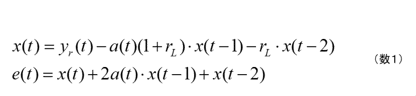
□適応アルゴリズム
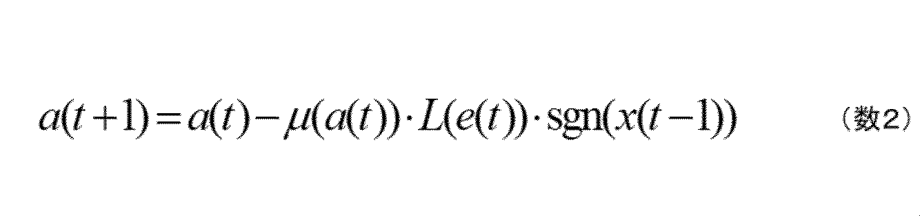
但し、a(t)はノッチ周波数(但し単位は[Hz]ではない)、rLはノッチ幅、μは更新量を調整する更新ゲインであり、L(Y)はYに対するリミッタ処理、sgnは符号関数、x(t)はノッチフィルタ状態、e(t)はノッチフィルタ出力を示す。
適応ノッチフィルタ34は、(数1)に示すノッチフィルタを内包しており、(数2)の適応アルゴリズムは、(数1)のノッチフィルタのノッチ周波数a(t)を適応調整するものである。
具体的には、入力である残振動yr(t)の主たる振動を(数1)のノッチフィルタが除去するように(数2)の適応アルゴリズムが反復動作し、(数1)のノッチフィルタにより残振動yr(t)の主たる振動の除去が完了した際のa(t)が、主たる振動の周波数となる。
したがって、適応ノッチフィルタ34は残振動yr(t)に対する逐次の周波数推定手段であるといえ、a(t)は残振動yr(t)に対する周波数推定値信号である。
なお、a(t)は周波数[Hz]に対して非線形な特性を有し、特にa(t)が100[Hz]以下の低域となる場合は、強い非線形性を示す。具体的には、単位周波数変化量の絶対値[Hz]当たりのa(t)の変化量絶対値は、周波数が低域な程、小さくなる傾向にある。したがって、低域の推定を行う際更新ゲインμが一定では、更新ゲインが大きすぎて、(数2)の適応アルゴリズムが振動的になり収束に至れない問題が生ずる。
そこで本実施例ではこの問題に対して、更新ゲインをμ(a(t))とし、周波数推定値信号に応じて変更されるものとする。一例として、μ(a(t))を以下の(数3)に示す。
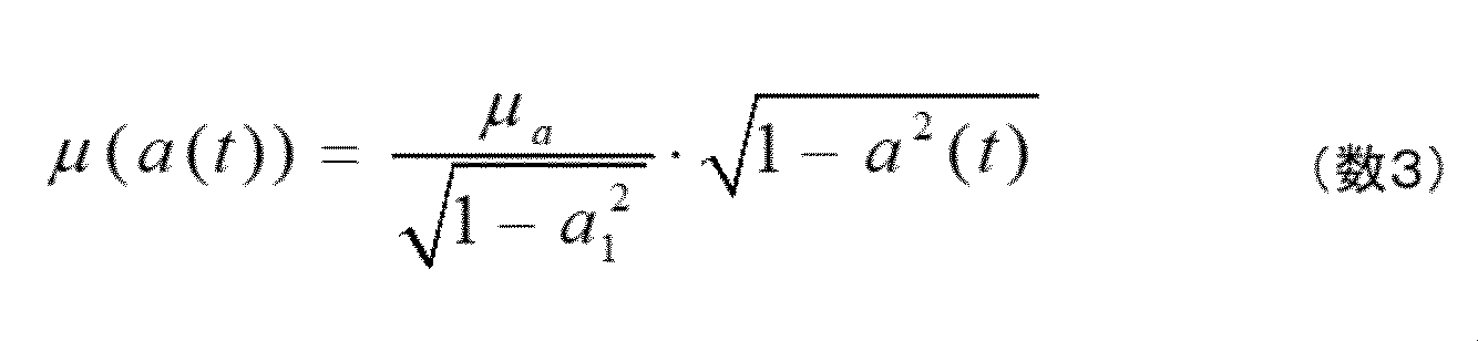
但し、a1は設計周波数であり、μaは基本更新ゲインである。
設計周波数a1において適切な更新ゲインをμaとした際、(数3)のμ(a(t))によれば、周波数a(t)<a1において、更新ゲインがμaと同等の大きさとみなされる。これにより、周波数a(t)<a1において、(数2)の適応アルゴリズムが振動的になり収束に至れない問題を解消できる。
なお、演算コスト削減のために(数3)をMAPのように、μとa(t)のデータを表形式にして保持するように実装してもよい。また、μ(a(t))は(数3)に類似の効果を持つ別の関数としてもよい。
適応ノッチフィルタ34のa(t)が収束すれば、(数1)のノッチフィルタが残振動yr(t)の主たる振動の除去を完了したと見なせ、残振動yr(t)の主たる振動の周波数を推定完了と判断できる。
周波数推定値信号a(t)が収束したか否かを判定する手段が収束判定部33である。収束判定部33は、周波数推定値信号a(t)を受けて、a(t)が収束したか否かを判断する。但し、前述のように周波数推定値信号a(t)は周波数[Hz]に対して非線形な特性となるため、a(t)を基に収束したか否かを判断するのは容易ではない。
収束判定部33は、a(t)を周波数[Hz]の単位に変換する変換手段を有し、これによりa(t)はf(t)[Hz]に変換される。したがって収束判定部33は、f(t)[Hz]を基にa(t)が収束したか否かを判断する。
具体的には、所定の時間内のf(t)の変動幅が、所定の値[Hz]以下になった場合、a(t)は収束したと判定し、このときのf(t)をk番目(k=1・・・)の値としてf(k)として保持し、逐次に収束判定を継続する。収束したと判定される毎にkはカウントUPされ、f(k)として保持され、この結果、収束判定部33はf(k)(k=1・・・)を、周波数推定値系列として出力する。
自動調整部2の調整開始から終了までの所定の時間に、逐次周波数推定部3は実行され、所定の時間分の周波数推定値系列f(k)(k=1・・・)を逐次周波数推定部3から得ることができる。
逐次周波数推定部3における、周波数推定値系列f(k)の算出の様子を図4に示す。図4において、各振動yd1(t)、及びyd2(t)の各々の周波数はf1=10[Hz]及びf2=20[Hz]とし、両振動が重畳した振動yd(t)に対して、自動調整部2の調整時間の間に、逐次周波数推定部3が動作した場合のf(t)を破線で、f(t)に対して収束判定が成された周波数推定値系列f(k)を実線で示している。
また図4において、ノッチフィルタ31の出力であるyr(t)をyr(t)=yd1r(t)+yd2r(t)として、各々のyd1r(t)及びyd2r(t)を示している。
収束判定k=1、2で振動yd(t)の主たる振動成分である振動yd1(t)の周波数f1が適応ノッチフィルタ34にて推定され、f(1)、f(2)がノッチフィルタ31に適用される。このためk=1、2では、yd1r(t)は振幅が小さくなり、振動yd(t)の主たる振動成分はyd2(t)になる。
これにより、k=3、4で振動yd2(t)の周波数f2が適応ノッチフィルタ34にて推定され、f(3)、f(4)がノッチフィルタ31に適用され、振動yd(t)の主たる振動成分はyd1(t)となる。
適応ノッチフィルタ34はyd1(t)の周波数を推定しf(5)を得るが、k=5以降、振動yd(t)は減衰しきって振動未発生状態となるので、振動検出部32は振動検出無と判断し、適応ノッチフィルタ34、及び収束判定部33の動作を停止する。
このように本実施例の逐次周波数推定部3は、1つ以上の減衰する振動が重畳してyd(t)して観測される場合であっても、主たる振動の周波数を優先的に、交番しながら高速に推定できる点が特徴である。
振動の振幅、周波数、減衰(持続)時間、振動の重畳数が未知の場合、例えば逐次最小2乗同定法のような一般的な同定手段では必ずしも、各振動の周波数を精度よく推定できない。例えば2種の振動yd1及びyd2が重畳するyd(t)であって、かつ減衰時間がT1<T2であるような場合、0~T1では2振動系であるが、T1~T2では1振動系であり、振動系の次数が、未知な減衰(持続)時間T1及びT2で変化する、時変形の同定問題になるためである。
これに対し、逐次周波数推定部3は、減衰(持続)時間、振動の重畳数が未知であっても、適切かつ高速に振動の周波数を推定できる利点がある。
制振制御設計部4は、制振制御部5を周波数推定値系列に基づいて調整する。本実施例において制振制御設計部4は、教師無しクラスタリングを行うものとする。
具体的には、自動調整部2の所定の調整時間に得られた、周波数推定値系列f(k)(k=1・・・)を点群データと見なし、これに対してk-means法等の教師無しクラスタリングを実施し、これにより得られたクラスタ数を振動の重畳数Nとし、各クラスタの平均値を各振動の周波数の推定値fk(k=1・・・N)とする。なお各クラスタの重心距離が所定値以下の場合は、それらクラスタは併合されるものとする。
制振制御設計部4は振動の重畳数N、及び各振動の周波数の推定値fk(k=1・・・N)といった出力Fを制振制御部5に送り、制振制御部5はノッチ周波数をfkとする実ノッチフィルタをN段直列に設けることで、自動調整部2の処理は完了となる。
図4に示すf(k)に対する制振制御設計部4の処理を示したのが図5である。クラスタ1はf(1)、f(2)、およびf(5)から、クラスタ2はf(3)及びf(4)から構成され、クラスタが2つゆえ振動の重畳数Nは2、各振動の周波数は各クラスタの平均値(f(1)+f(2)+f(5))/3、及び(f(3)+f(4))/2となる。
なお、自動調整開始直後のf(1)は、ノッチフィルタ31が無効の状態、振動の重畳が顕著のため、周波数の推定値としては精度が低くなる傾向にある。このため、クラスタリング前に周波数推定値系列f(k)(k=1・・・)の前半部分を間引く処理を加えてもよい。
制振制御設計部4は、前述の教師無しクラスタリングの採用以外にも、振動の重畳数Nが1~2の場合は、下記のアルゴリズムの採用が考えられる。下記はk-means法と比較して処理コストに優れる点が特徴である。
S1:点群データの平均値Maを算出し、Maに対する大小で2つのクラスタ
C1、C2を生成
S2:C1の平均値Mc1、C2の平均値Mc2を算出し、
Te=|Mc1-Mc2|を算出する。
C1、C2を生成
S2:C1の平均値Mc1、C2の平均値Mc2を算出し、
Te=|Mc1-Mc2|を算出する。
S3:Teが所定の値以上の場合、振動の重畳数はN=2、各振動の周波数の推定値はf1=Mc1、f2=Mc2とする。Teが所定の値より小さい場合は、振動の重畳数はN=1、振動の周波数の推定値はf1=Maとする。
自動調整部2の所定の調整時間は、制御対象機械15の1回の動作でyd(t)に振動が観測され、周波数推定値系列f(k)が得られるならば、制御対象機械15の1回の動作にかかる時間のみであってもよい。
また周波数推定値系列f(k)(k=1・・・)を多く取得し振動の周波数の推定精度を高めたい場合は、制御対象機械15の複数回の動作に必要な時間を自動調整部2の所定の調整時間に設定してもよい。
本実施例によれば、1つ以上の制御対象機械の共振・反共振特性に起因した振動がモータ制御系の応答から観測され、機械端に振動が発生する場合に、特に前記機械共振の数を事前に把握する必要ない。
特許文献1では、制振制御設定部から制振制御部であるフィードフォワード制御部が複数の共振特性の反復調整をすることになる。本実施例によれば、制振制御部の調整を開始する初期状態において制振制御部5は、モータ制御系に入力される指令を加工せず、制振制御設計部4が周波数推定値系列に基づいて制振制御部5の調整を完了した後に、制振制御部5はモータ制御系に入力される指令の加工を開始する。本実施例では短時間・リアルタイムに制振制御部5を調整し、機械端の振動を抑制可能なモータ制御の自動調整方法及び、自動調整部2を備えた、モータ制御装置を提供することが可能である。
なお本実施例では、自動調整部2はモータ回転位置y(t)を入力としたが、振動成分の抽出のしやすさの観点から、自動調整部2の入力をモータ回転位置偏差や、FB制御器13の出力、モータ回転速度の偏差、速度FB制御器の出力、もしくはモータ回転速度の応答等を用いてもよい。
また制振制御設計部4で生成されたクラスタの分散の大小に基づき、実ノッチフィルタの幅を可変にしてもよい。クラスタの分散が大の場合は、周波数推定値の精度が期待しづらいことが考えられるため、実ノッチフィルタの幅を大きめに設定し、広く周波数成分を除去することが有効な場合があるためである。
またノッチフィルタ31は、直列に複数段並べた構成とし、各ノッチ周波数に適宜周波数推定値系列f(k)を適用してもよい。これにより、多数の振動の重畳がyd(t)から観測される場合でも、周波数の推定精度が期待できるものとなる。但しこの場合、f(k)をどのノッチフィルタに適用するかをマネジメントする処理が別途必要となる点に注意する。
また自動調整部2は、FB制御器13のゲインを調整する機能を有していてもよい。制振制御部5が自動調整部2により調整され、これが有効になると、機械端の振動が抑制され、より高いFB制御ゲインであっても、振動の発生無く機械端を制御・位置決めできるようになるためである。
図1の自動調整部2、加減算器16、FB制御器13を含むモータ制御装置は、図示は省略したがCPU(Central Processing Unit)を有する。振動抽出フィルタ6、逐次周波数推定部3、制振制御設計部4、制振制御部5の各処理部を含む自動調整部2、加減算器16、FB制御器13は、CPUがプログラムを読み出してプログラムを実行することで、各処理部の処理が実行される。ASIC(Application Specific Integrated Circuit)やFPGA(Field Programmable Gate Array)等のハードウェアで、各処理部の全部もしくは一部を構成することもできる。
本実施例によれば、セミクローズド構成のモータFB制御系において、機械端に振動が発生する場合に、特に機械共振の数を事前に把握する必要なく、短時間・リアルタイムに制振制御部を調整し、機械端の振動を抑制可能である。
実施例2は、実施例1をモータ制御装置に適用した例である。実施例1と同じ事項は説明を省略する。図6に示すように、図1に示した自動調整部2を自動調整器622としてACサーボモータのセミクローズド位置FB制御系へ適用した実施例である。図6において自動調整器622を含まない場合は一般に知られる、セミクローズド位置FB制御系である。
ACサーボモータのセミクローズド位置FB制御系は、図6に示されるように、加減算器612、加減算器614、位置制御器61、速度制御器62、電流制御器63、d-q座標系から3相座標系へ座標変換する第1の座標変換器64、3相座標系からd-q座標系へ座標変換する第2の座標変換器610、3相電圧指令を入力してPWMパルスを出力するPWM出力器65、スイッチング素子を有するインバータ(電力変換器)66、電流検出器68、位置・速度算出部611、自動調整器622、モータの回転数を計測するエンコーダ69、モータ67、モータに駆動される機械613を備える。
エンコーダ69の出力からモータの回転位置・速度を算出する位置・速度算出部611で算出されたモータ回転位置もしくはモータ回転速度616を、自動調整器622は入力する。
機械613の端部(機械端)の振動を励起しないように、自動調整器622の制振制御部5は回転位置指令615を加工し、加工後回転位置指令617を出力し、自動調整器622は、制振制御部5をモータ回転位置616に基づき適切に自動調整する役割を担う。
自動調整器622から出力された加工後回転位置指令617と位置・速度算出部611からのモータ回転位置616とを加減算器614が入力し、加工後回転位置指令617とモータ回転位置616との差分を位置制御器61が位置指令として入力する。
位置制御器61は、速度指令618を出力し、加減算器612が速度指令618とモータ回転速度619の差分を速度制御器62に出力ずる。
位置制御器61は加工後回転位置指令617を指令とし、マイナーループ系の速度・電流制御系、及び積分要素を制御対象として位置FB制御を実施する。
機械613の慣性数は1とし、機械613とモータのロータが弾性結合されているとみなされる場合は、制御対象機械は機械613とモータのロータがバネ・ダンパで結合された2慣性系とみなすことができ、制御対象機械は1組の共振・反共振特性を含む周波数特性を有するものとなる。
また、機械613の慣性数が2で、双方が弾性結合されまたどちらか一方がモータのロータに対して弾性結合されているとみなされる場合、もしくは機械613も2つの慣性がモータのロータに対して各々弾性結合されているとみなされる場合には制御対象機械は3慣性系とみなすことができ、2組の共振・反共振特性を含む周波数特性を有するものとなる。このような系の例としては、例えば慣性体が移動する2慣性のサーボモータ機構が剛性の低い架台の上に設置されている場合等である。
実施例1で示したように、自動調整器622は機械の共振・反共振特性の事前調査の必要なく、機械端が振動しモータ制御系の応答に複数の振動が重畳して観測される場合であっても、短時間・リアルタイムに制振制御部5を適切に自動調整し、機械端の振動の抑制が可能である。したがって、本実施例においても自動調整器622は実施例1と同様に短時間・リアルタイムに制振制御部5を適切に自動調整し、機械端の振動を抑制することが可能である。
本実施例によれば、図6に示すようなACサーボモータのセミクローズド位置FB制御系において、1つ以上の制御対象機械の共振・反共振特性に起因した振動がモータ制御系の応答から観測され、機械端に振動が発生する場合であっても、自動調整器622を設けることで、特に前記機械共振の数を事前に把握する必要ない。さらに、本実施例によれば、短時間・リアルタイムに制振制御部5を適切に自動調整し、機械端の振動を抑制することが可能である。
なお自動調整器622は、図7に示すように、ACサーボモータのセミクローズド速度FB制御系へ適用することも可能である。図7では、図6の位置制御器61は除かれている。速度FB制御系であっても、1つ以上の制御対象機械の共振・反共振特性に起因した振動は速度応答716から観測でき、機械端の振動は発生しうるためである。
図7において、機械613の端部(機械端)の振動を励起しないように、自動調整器622の制振制御部5は速度指令715を加工し、加工された速度指令717を出力する。加工された速度指令717と、位置・速度算出部611からのモータ回転速度716の差分を加減算器612が速度制御器62に出力ずる。
自動調整器622は速度応答716を用いても実施例1で示したように制振制御部5を自動調整可能である。これにより図7に示すようなACサーボモータのセミクローズド速度FB制御系であっても自動調整器622を設けることで、特に前記機械共振の数を事前に把握する必要ない。
さらに、図7のACサーボモータのセミクローズド速度FB制御系であっても短時間・リアルタイムに制振制御部5を適切に自動調整し、機械端の振動を抑制することが可能である。
本実施例によれば、ACサーボモータのセミクローズド位置FB制御系もしくはACサーボモータのセミクローズド速度FB制御系において、機械端に振動が発生する場合に、特に機械共振の数を事前に把握する必要なく、短時間・リアルタイムに制振制御部を調整し、機械端の振動を抑制可能である。
なお上記の実施例は、モータ制御装置以外にも、例えば半導体検査装置、電気自動車の主モータ制御装置、電動パワーステアリングなどへの適用が可能である。
2…自動調整部、3…逐次周波数推定部、4…制振制御設計部、5…制振制御部、6…振動抽出フィルタ、13…FB制御器、14…モータ、15…制御対象機械、31…ノッチフィルタ、32…振動検出部、33…収束判定部、34…適応ノッチフィルタ
Claims (11)
- 複数の機械共振起因でモータ制御系の応答に重畳する複数の振動を、モータの回転速度応答もしくは回転位置応答から抽出する振動抽出フィルタと、
前記振動抽出フィルタから得られる前記複数の振動の各々の周波数を逐次に1つ1つ推定し、周波数の推定結果を周波数推定値系列として出力する逐次周波数推定部と、
前記モータに取り付けられた機械の端部に生ずる振動を抑制するように前記モータ制御系に入力される指令を加工する制振制御部と、
前記制振制御部を前記周波数推定値系列に基づいて調整する制振制御設計部とを備えるモータ制御装置。 - 請求項1に記載のモータ制御装置において、
前記逐次周波数推定部は、
所定の周波数成分のみを除去する振動除去部と、
振動波形から振動の周波数を逐次に推定する適応推定部と、
収束判定部と、
振動検出部とを備え、
前記振動除去部は、
前記複数の振動を処理し、前記複数の振動から所定の周波数成分が除去された信号を残振動信号として出力し、
前記適応推定部は、
前記残振動信号の主たる1つの振動の周波数を逐次に推定し、その推定値を周波数推定値信号として逐次に出力し、
前記収束判定部は、
前記周波数推定値信号が収束したか否かを判定し、
収束したと判定した際の前記周波数推定値信号の周波数推定値を前記周波数推定値系列として出力し、
前記振動除去部は、
前記周波数推定値系列に基づき、除去する前記所定の周波数成分を変化させ、
前記振動検出部は、前記残振動信号において振動が持続的に発生しているか否かを判断し、
振動発生を検出した場合に、前記適応推定部及び前記収束判定部を動作させるモータ制御装置。 - 請求項1に記載のモータ制御装置において、
前記制振制御設計部は、
前記周波数推定値系列の、所定の時間分を点群データとして取り扱い、
前記点群データを教師無しのクラスタリングで複数のクラスタに分割し、
分割された前記クラスタの数を、前記複数の振動の、振動の重畳数とし、
各クラスタに属する点群データから前記複数の振動の、各々の振動の周波数を推定して振動周波数推定値とし、
前記重畳数と前記振動周波数推定値に基づいて、前記制振制御部を調整するモータ制御装置。 - 請求項2に記載のモータ制御装置において、
前記振動除去部は、
ノッチフィルタであり、
前記適応推定部は、
適応ノッチフィルタであり、
前記収束判定部は、
前記適応ノッチフィルタが逐次推定する前記複数の振動の主たる1つの振動の周波数を前記周波数推定値信号として逐次に受けとり、前記周波数推定値系列を出力し、
前記ノッチフィルタは、
出力される前記周波数推定値系列に基づき、前記ノッチフィルタのノッチ周波数を変化させるモータ制御装置。 - 請求項4に記載のモータ制御装置において、
前記制振制御部の調整を開始する初期状態において、
前記ノッチフィルタのノッチ周波数は、前記制振制御部が担う前記機械の端部の制振帯域の上限以上とするモータ制御装置。 - 請求項1に記載のモータ制御装置において、
前記制振制御部の調整を開始する初期状態においては、
前記制振制御部は、
前記モータ制御系に入力される指令を加工せず、
前記制振制御設計部が前記周波数推定値系列に基づいて前記制振制御部の調整を完了した後に、前記制振制御部は前記モータ制御系に入力される指令の加工を開始するモータ制御装置。 - 請求項3に記載のモータ制御装置において、
前記点群データの平均値を基に、前記点群データを2つのクラスタに分割し、各クラスタの平均値を算出し、
算出された前記平均値の差の絶対値が所定の値以上の場合、振動の重畳数を2、そうでないない場合は1とし、
前記振動の重畳数が2の場合、各クラスタの平均値を前記振動周波数推定値とし、前記振動の重畳数が1の場合、前記点群データの平均値を前記振動周波数推定値とするモータ制御装置。 - 請求項4に記載のモータ制御装置において、
前記適応ノッチフィルタは、
逐次に周波数を推定する際、周波数の逐次更新における更新ゲインを、現時点の周波数推定値に基づいて、可変にするモータ制御装置。 - 複数の機械共振起因でモータ制御系の応答に重畳する複数の振動を、モータの回転速度応答もしくは回転位置応答から抽出し、
抽出した前記複数の振動の各々の周波数を逐次に1つ1つ推定し、周波数の推定結果を周波数推定値系列として出力し、
前記周波数推定値系列に基づいて調整することで、前記モータに取り付けられた機械の端部に生ずる振動を抑制するように前記モータ制御系に入力される指令を加工するモータ制御の自動調整方法。 - 請求項9に記載のモータ制御の自動調整方法において、
初期状態においては、
前記モータ制御系に入力される前記指令を加工せず、
前記周波数推定値系列に基づいて前記指令の調整を完了した後に、前記モータ制御系に入力される前記指令の加工を開始するモータ制御の自動調整方法。 - 請求項9に記載のモータ制御の自動調整方法において、
前記複数の振動の各々の周波数の逐次1つ1つの推定は、
ノッチフィルタと、適応ノッチフィルタと、前記適応ノッチフィルタの収束の判定との組み合わせで実行されるモータ制御の自動調整方法。
Priority Applications (2)
| Application Number | Priority Date | Filing Date | Title |
|---|---|---|---|
| CN202180060997.8A CN116194849B (zh) | 2020-09-07 | 2021-07-08 | 电动机控制装置 |
| EP21863954.0A EP4212968A4 (en) | 2020-09-07 | 2021-07-08 | ENGINE CONTROL DEVICE |
Applications Claiming Priority (2)
| Application Number | Priority Date | Filing Date | Title |
|---|---|---|---|
| JP2020-149999 | 2020-09-07 | ||
| JP2020149999A JP7390267B2 (ja) | 2020-09-07 | 2020-09-07 | モータ制御装置 |
Publications (1)
| Publication Number | Publication Date |
|---|---|
| WO2022049896A1 true WO2022049896A1 (ja) | 2022-03-10 |
Family
ID=80491112
Family Applications (1)
| Application Number | Title | Priority Date | Filing Date |
|---|---|---|---|
| PCT/JP2021/025870 Ceased WO2022049896A1 (ja) | 2020-09-07 | 2021-07-08 | モータ制御装置 |
Country Status (5)
| Country | Link |
|---|---|
| EP (1) | EP4212968A4 (ja) |
| JP (1) | JP7390267B2 (ja) |
| CN (1) | CN116194849B (ja) |
| TW (1) | TWI793692B (ja) |
| WO (1) | WO2022049896A1 (ja) |
Citations (3)
| Publication number | Priority date | Publication date | Assignee | Title |
|---|---|---|---|---|
| WO2012056868A1 (ja) | 2010-10-27 | 2012-05-03 | 三菱電機株式会社 | 電動機制御装置 |
| JP2020017071A (ja) * | 2018-07-25 | 2020-01-30 | 株式会社日立産機システム | フィードバック制御系の自動調整方法およびフィードバック制御装置 |
| WO2020250469A1 (ja) * | 2019-06-14 | 2020-12-17 | 株式会社日立産機システム | モータ制御装置、ノッチフィルタ調整装置、ノッチフィルタ調整方法 |
Family Cites Families (12)
| Publication number | Priority date | Publication date | Assignee | Title |
|---|---|---|---|---|
| US6936990B2 (en) * | 2002-03-29 | 2005-08-30 | Matsushita Electric Industrial Co., Ltd. | Method for controlling electric motor and apparatus for controlling the same |
| JP4329438B2 (ja) * | 2003-07-17 | 2009-09-09 | 三菱電機株式会社 | 電動機制御装置 |
| JP5258013B2 (ja) * | 2007-03-02 | 2013-08-07 | 新東工業株式会社 | 天井クレーンによる搬送方法およびこの搬送方法を利用した天井クレーンシステム |
| JP4238273B2 (ja) * | 2007-07-02 | 2009-03-18 | ファナック株式会社 | 制御装置 |
| JP2009048462A (ja) * | 2007-08-21 | 2009-03-05 | Mitsuba Corp | 機械的共振周波数補償装置 |
| US8560129B2 (en) * | 2008-05-14 | 2013-10-15 | Sinfonia Technology Co., Ltd. | Vibration control device and vehicle |
| JP5332321B2 (ja) * | 2008-06-04 | 2013-11-06 | パナソニック株式会社 | モータ制御装置 |
| JP6041762B2 (ja) * | 2013-07-09 | 2016-12-14 | 山洋電気株式会社 | モータ制御装置 |
| CN103499443B (zh) * | 2013-09-12 | 2016-01-20 | 西安交通大学 | 一种齿轮故障无键相角域平均计算阶次分析方法 |
| CN111400959B (zh) * | 2018-12-27 | 2024-01-30 | 北京金风科创风电设备有限公司 | 风力发电机组的叶片故障诊断方法及装置 |
| WO2020157919A1 (ja) * | 2019-01-31 | 2020-08-06 | 三菱電機株式会社 | 機械学習装置、およびモータ制御システム |
| CN110863957A (zh) * | 2019-11-06 | 2020-03-06 | 华电电力科学研究院有限公司 | 一种风电机组预测检修周期避免机组非计划停运装置及设计方法 |
-
2020
- 2020-09-07 JP JP2020149999A patent/JP7390267B2/ja active Active
-
2021
- 2021-07-08 CN CN202180060997.8A patent/CN116194849B/zh active Active
- 2021-07-08 WO PCT/JP2021/025870 patent/WO2022049896A1/ja not_active Ceased
- 2021-07-08 EP EP21863954.0A patent/EP4212968A4/en active Pending
- 2021-08-02 TW TW110128348A patent/TWI793692B/zh active
Patent Citations (3)
| Publication number | Priority date | Publication date | Assignee | Title |
|---|---|---|---|---|
| WO2012056868A1 (ja) | 2010-10-27 | 2012-05-03 | 三菱電機株式会社 | 電動機制御装置 |
| JP2020017071A (ja) * | 2018-07-25 | 2020-01-30 | 株式会社日立産機システム | フィードバック制御系の自動調整方法およびフィードバック制御装置 |
| WO2020250469A1 (ja) * | 2019-06-14 | 2020-12-17 | 株式会社日立産機システム | モータ制御装置、ノッチフィルタ調整装置、ノッチフィルタ調整方法 |
Non-Patent Citations (1)
| Title |
|---|
| See also references of EP4212968A4 |
Also Published As
| Publication number | Publication date |
|---|---|
| EP4212968A4 (en) | 2024-10-16 |
| TW202211613A (zh) | 2022-03-16 |
| TWI793692B (zh) | 2023-02-21 |
| CN116194849A (zh) | 2023-05-30 |
| JP7390267B2 (ja) | 2023-12-01 |
| JP2022044396A (ja) | 2022-03-17 |
| EP4212968A1 (en) | 2023-07-19 |
| CN116194849B (zh) | 2026-01-27 |
Similar Documents
| Publication | Publication Date | Title |
|---|---|---|
| JP6044647B2 (ja) | ダイナモメータの制御装置及びこれを用いた慣性モーメント推定方法 | |
| US9525378B2 (en) | Motor control device | |
| JP4720744B2 (ja) | サーボ制御装置 | |
| JP5757842B2 (ja) | 共振抑制装置及び共振抑制方法 | |
| EP3828650B1 (en) | Automatic adjustment method for feedback control system, and feedback control system | |
| JP2010148178A (ja) | イナーシャ推定を行う制御装置及び制御システム | |
| US8872462B2 (en) | Motor control device | |
| CN113557479B (zh) | 电动机控制装置、陷波滤波器调整装置、陷波滤波器调整方法 | |
| CN114223129A (zh) | 电动机控制装置及其自动调整方法 | |
| WO2022049896A1 (ja) | モータ制御装置 | |
| CN111566928A (zh) | 电动机的控制装置 | |
| JP2009048462A (ja) | 機械的共振周波数補償装置 | |
| JP7690419B2 (ja) | モータ制御装置、およびその自動調整方法 | |
| US9712095B2 (en) | Efficient damping of vibrations of an electric machine | |
| US11569709B2 (en) | Motor drive device and servo adjustment method | |
| KR102756493B1 (ko) | 모터 제어 장치 | |
| US11831262B2 (en) | Motor control device | |
| US11101760B2 (en) | Electric motor control device | |
| KR102276198B1 (ko) | 서보 시스템의 난제성 진동 제어 장치 및 방법 | |
| CN114946120B (zh) | 电动机控制装置 | |
| WO2022138797A1 (ja) | 振動情報算出装置、振動情報算出方法、および、プログラム | |
| JP2012247972A (ja) | フィードバック制御装置、フィードバック制御方法、モータ及びロボット |
Legal Events
| Date | Code | Title | Description |
|---|---|---|---|
| 121 | Ep: the epo has been informed by wipo that ep was designated in this application |
Ref document number: 21863954 Country of ref document: EP Kind code of ref document: A1 |
|
| NENP | Non-entry into the national phase |
Ref country code: DE |
|
| ENP | Entry into the national phase |
Ref document number: 2021863954 Country of ref document: EP Effective date: 20230411 |