WO2022049914A1 - 再生制御装置 - Google Patents
再生制御装置 Download PDFInfo
- Publication number
- WO2022049914A1 WO2022049914A1 PCT/JP2021/027152 JP2021027152W WO2022049914A1 WO 2022049914 A1 WO2022049914 A1 WO 2022049914A1 JP 2021027152 W JP2021027152 W JP 2021027152W WO 2022049914 A1 WO2022049914 A1 WO 2022049914A1
- Authority
- WO
- WIPO (PCT)
- Prior art keywords
- injection amount
- late post
- post injection
- temperature
- doc
- Prior art date
- Legal status (The legal status is an assumption and is not a legal conclusion. Google has not performed a legal analysis and makes no representation as to the accuracy of the status listed.)
- Ceased
Links
Images




Classifications
-
- F—MECHANICAL ENGINEERING; LIGHTING; HEATING; WEAPONS; BLASTING
- F01—MACHINES OR ENGINES IN GENERAL; ENGINE PLANTS IN GENERAL; STEAM ENGINES
- F01N—GAS-FLOW SILENCERS OR EXHAUST APPARATUS FOR MACHINES OR ENGINES IN GENERAL; GAS-FLOW SILENCERS OR EXHAUST APPARATUS FOR INTERNAL-COMBUSTION ENGINES
- F01N3/00—Exhaust or silencing apparatus having means for purifying, rendering innocuous, or otherwise treating exhaust
- F01N3/02—Exhaust or silencing apparatus having means for purifying, rendering innocuous, or otherwise treating exhaust for cooling, or for removing solid constituents of, exhaust
- F01N3/021—Exhaust or silencing apparatus having means for purifying, rendering innocuous, or otherwise treating exhaust for cooling, or for removing solid constituents of, exhaust by means of filters
- F01N3/033—Exhaust or silencing apparatus having means for purifying, rendering innocuous, or otherwise treating exhaust for cooling, or for removing solid constituents of, exhaust by means of filters in combination with other devices
- F01N3/035—Exhaust or silencing apparatus having means for purifying, rendering innocuous, or otherwise treating exhaust for cooling, or for removing solid constituents of, exhaust by means of filters in combination with other devices with catalytic reactors
-
- F—MECHANICAL ENGINEERING; LIGHTING; HEATING; WEAPONS; BLASTING
- F01—MACHINES OR ENGINES IN GENERAL; ENGINE PLANTS IN GENERAL; STEAM ENGINES
- F01N—GAS-FLOW SILENCERS OR EXHAUST APPARATUS FOR MACHINES OR ENGINES IN GENERAL; GAS-FLOW SILENCERS OR EXHAUST APPARATUS FOR INTERNAL-COMBUSTION ENGINES
- F01N3/00—Exhaust or silencing apparatus having means for purifying, rendering innocuous, or otherwise treating exhaust
- F01N3/08—Exhaust or silencing apparatus having means for purifying, rendering innocuous, or otherwise treating exhaust for rendering innocuous
- F01N3/10—Exhaust or silencing apparatus having means for purifying, rendering innocuous, or otherwise treating exhaust for rendering innocuous by thermal or catalytic conversion of noxious components of exhaust
- F01N3/103—Oxidation catalysts for HC and CO only
-
- F—MECHANICAL ENGINEERING; LIGHTING; HEATING; WEAPONS; BLASTING
- F01—MACHINES OR ENGINES IN GENERAL; ENGINE PLANTS IN GENERAL; STEAM ENGINES
- F01N—GAS-FLOW SILENCERS OR EXHAUST APPARATUS FOR MACHINES OR ENGINES IN GENERAL; GAS-FLOW SILENCERS OR EXHAUST APPARATUS FOR INTERNAL-COMBUSTION ENGINES
- F01N11/00—Monitoring or diagnostic devices for exhaust-gas treatment apparatus
- F01N11/002—Monitoring or diagnostic devices for exhaust-gas treatment apparatus the diagnostic devices measuring or estimating temperature or pressure in, or downstream of the exhaust apparatus
-
- F—MECHANICAL ENGINEERING; LIGHTING; HEATING; WEAPONS; BLASTING
- F01—MACHINES OR ENGINES IN GENERAL; ENGINE PLANTS IN GENERAL; STEAM ENGINES
- F01N—GAS-FLOW SILENCERS OR EXHAUST APPARATUS FOR MACHINES OR ENGINES IN GENERAL; GAS-FLOW SILENCERS OR EXHAUST APPARATUS FOR INTERNAL-COMBUSTION ENGINES
- F01N3/00—Exhaust or silencing apparatus having means for purifying, rendering innocuous, or otherwise treating exhaust
- F01N3/02—Exhaust or silencing apparatus having means for purifying, rendering innocuous, or otherwise treating exhaust for cooling, or for removing solid constituents of, exhaust
- F01N3/021—Exhaust or silencing apparatus having means for purifying, rendering innocuous, or otherwise treating exhaust for cooling, or for removing solid constituents of, exhaust by means of filters
-
- F—MECHANICAL ENGINEERING; LIGHTING; HEATING; WEAPONS; BLASTING
- F01—MACHINES OR ENGINES IN GENERAL; ENGINE PLANTS IN GENERAL; STEAM ENGINES
- F01N—GAS-FLOW SILENCERS OR EXHAUST APPARATUS FOR MACHINES OR ENGINES IN GENERAL; GAS-FLOW SILENCERS OR EXHAUST APPARATUS FOR INTERNAL-COMBUSTION ENGINES
- F01N3/00—Exhaust or silencing apparatus having means for purifying, rendering innocuous, or otherwise treating exhaust
- F01N3/02—Exhaust or silencing apparatus having means for purifying, rendering innocuous, or otherwise treating exhaust for cooling, or for removing solid constituents of, exhaust
- F01N3/021—Exhaust or silencing apparatus having means for purifying, rendering innocuous, or otherwise treating exhaust for cooling, or for removing solid constituents of, exhaust by means of filters
- F01N3/023—Exhaust or silencing apparatus having means for purifying, rendering innocuous, or otherwise treating exhaust for cooling, or for removing solid constituents of, exhaust by means of filters using means for regenerating the filters, e.g. by burning trapped particles
-
- F—MECHANICAL ENGINEERING; LIGHTING; HEATING; WEAPONS; BLASTING
- F01—MACHINES OR ENGINES IN GENERAL; ENGINE PLANTS IN GENERAL; STEAM ENGINES
- F01N—GAS-FLOW SILENCERS OR EXHAUST APPARATUS FOR MACHINES OR ENGINES IN GENERAL; GAS-FLOW SILENCERS OR EXHAUST APPARATUS FOR INTERNAL-COMBUSTION ENGINES
- F01N3/00—Exhaust or silencing apparatus having means for purifying, rendering innocuous, or otherwise treating exhaust
- F01N3/02—Exhaust or silencing apparatus having means for purifying, rendering innocuous, or otherwise treating exhaust for cooling, or for removing solid constituents of, exhaust
- F01N3/021—Exhaust or silencing apparatus having means for purifying, rendering innocuous, or otherwise treating exhaust for cooling, or for removing solid constituents of, exhaust by means of filters
- F01N3/023—Exhaust or silencing apparatus having means for purifying, rendering innocuous, or otherwise treating exhaust for cooling, or for removing solid constituents of, exhaust by means of filters using means for regenerating the filters, e.g. by burning trapped particles
- F01N3/025—Exhaust or silencing apparatus having means for purifying, rendering innocuous, or otherwise treating exhaust for cooling, or for removing solid constituents of, exhaust by means of filters using means for regenerating the filters, e.g. by burning trapped particles using fuel burner or by adding fuel to exhaust
- F01N3/0253—Exhaust or silencing apparatus having means for purifying, rendering innocuous, or otherwise treating exhaust for cooling, or for removing solid constituents of, exhaust by means of filters using means for regenerating the filters, e.g. by burning trapped particles using fuel burner or by adding fuel to exhaust adding fuel to exhaust gases
-
- F—MECHANICAL ENGINEERING; LIGHTING; HEATING; WEAPONS; BLASTING
- F01—MACHINES OR ENGINES IN GENERAL; ENGINE PLANTS IN GENERAL; STEAM ENGINES
- F01N—GAS-FLOW SILENCERS OR EXHAUST APPARATUS FOR MACHINES OR ENGINES IN GENERAL; GAS-FLOW SILENCERS OR EXHAUST APPARATUS FOR INTERNAL-COMBUSTION ENGINES
- F01N9/00—Electrical control of exhaust gas treating apparatus
- F01N9/002—Electrical control of exhaust gas treating apparatus of filter regeneration
-
- F—MECHANICAL ENGINEERING; LIGHTING; HEATING; WEAPONS; BLASTING
- F01—MACHINES OR ENGINES IN GENERAL; ENGINE PLANTS IN GENERAL; STEAM ENGINES
- F01N—GAS-FLOW SILENCERS OR EXHAUST APPARATUS FOR MACHINES OR ENGINES IN GENERAL; GAS-FLOW SILENCERS OR EXHAUST APPARATUS FOR INTERNAL-COMBUSTION ENGINES
- F01N2430/00—Influencing exhaust purification, e.g. starting of catalytic reaction, filter regeneration, or the like, by controlling engine operating characteristics
- F01N2430/08—Influencing exhaust purification, e.g. starting of catalytic reaction, filter regeneration, or the like, by controlling engine operating characteristics by modifying ignition or injection timing
-
- F—MECHANICAL ENGINEERING; LIGHTING; HEATING; WEAPONS; BLASTING
- F01—MACHINES OR ENGINES IN GENERAL; ENGINE PLANTS IN GENERAL; STEAM ENGINES
- F01N—GAS-FLOW SILENCERS OR EXHAUST APPARATUS FOR MACHINES OR ENGINES IN GENERAL; GAS-FLOW SILENCERS OR EXHAUST APPARATUS FOR INTERNAL-COMBUSTION ENGINES
- F01N2900/00—Details of electrical control or of the monitoring of the exhaust gas treating apparatus
- F01N2900/04—Methods of control or diagnosing
- F01N2900/0408—Methods of control or diagnosing using a feed-back loop
-
- F—MECHANICAL ENGINEERING; LIGHTING; HEATING; WEAPONS; BLASTING
- F01—MACHINES OR ENGINES IN GENERAL; ENGINE PLANTS IN GENERAL; STEAM ENGINES
- F01N—GAS-FLOW SILENCERS OR EXHAUST APPARATUS FOR MACHINES OR ENGINES IN GENERAL; GAS-FLOW SILENCERS OR EXHAUST APPARATUS FOR INTERNAL-COMBUSTION ENGINES
- F01N2900/00—Details of electrical control or of the monitoring of the exhaust gas treating apparatus
- F01N2900/06—Parameters used for exhaust control or diagnosing
- F01N2900/16—Parameters used for exhaust control or diagnosing said parameters being related to the exhaust apparatus, e.g. particulate filter or catalyst
- F01N2900/1602—Temperature of exhaust gas apparatus
-
- Y—GENERAL TAGGING OF NEW TECHNOLOGICAL DEVELOPMENTS; GENERAL TAGGING OF CROSS-SECTIONAL TECHNOLOGIES SPANNING OVER SEVERAL SECTIONS OF THE IPC; TECHNICAL SUBJECTS COVERED BY FORMER USPC CROSS-REFERENCE ART COLLECTIONS [XRACs] AND DIGESTS
- Y02—TECHNOLOGIES OR APPLICATIONS FOR MITIGATION OR ADAPTATION AGAINST CLIMATE CHANGE
- Y02T—CLIMATE CHANGE MITIGATION TECHNOLOGIES RELATED TO TRANSPORTATION
- Y02T10/00—Road transport of goods or passengers
- Y02T10/10—Internal combustion engine [ICE] based vehicles
- Y02T10/40—Engine management systems
Definitions
- the present disclosure relates to a regeneration control device for regenerating an exhaust gas treatment device having a DOC and a DPF arranged in an exhaust passage of a diesel engine.
- the diesel engine is equipped with an exhaust gas treatment device consisting of a DOC (diesel oxidation catalyst) arranged in the exhaust passage and a DPF (diesel particulate filter) arranged downstream of the DOC.
- the DPF is a device for collecting PM (particulate matter) contained in the exhaust gas discharged from a diesel engine.
- the DPF is generally configured by molding ceramic or the like into a honeycomb-shaped monolith, and adjacent ventilation holes are alternately closed on the inlet side and the outlet side so that the exhaust gas passes through the filtration wall, and PM is removed by this filtration wall.
- Some DPFs carry a catalyst.
- the DOC is generally formed by molding ceramic or the like into a honeycomb-shaped monolith, and supports an oxidation catalyst on the inner surface thereof.
- the forced regeneration of the DPF is performed by raising the exhaust gas temperature and forcibly raising the temperature of the DPF. For example, this temperature rise is performed by delaying fuel injection timing, post injection, intake or exhaust throttle, and the like.
- the upper limit value of the injection amount is determined only by the air-fuel ratio, and the upper limit value of the injection amount is determined regardless of the DOC temperature.
- the injection amount must be limited so that white smoke is not generated regardless of the DOC temperature. Therefore, the injection amount must be set to be small so that white smoke is not generated at any temperature, and the control is executed so as to excessively suppress the injection amount, and the DPF regeneration time increases. There is a risk.
- the present disclosure realizes fine control so as not to excessively suppress the late post injection amount injected at a timing that does not contribute to in-cylinder combustion, and generates white smoke without increasing the DPF regeneration time.
- the purpose is to reduce.
- the reproduction control device is In an exhaust gas treatment device of a diesel engine provided with a diesel oxidation catalyst (DOC) arranged in an exhaust passage of an internal combustion engine and a diesel particulate filter (DPF) arranged downstream of the DOC, the temperature of the DPF is increased to the DPF.
- the late post injection amount determining unit is configured to determine an upper limit value of the late post injection amount based on the excess air ratio of the exhaust gas flowing into the DOC acquired based on the temperature index of the DOC. ..
- fine control can be realized so as not to excessively suppress the late post injection amount, and the generation of white smoke can be reduced without increasing the DPF regeneration time.
- expressions such as “same”, “equal”, and “homogeneous” that indicate that things are in the same state not only represent exactly the same state, but also have tolerances or differences to the extent that the same function can be obtained. It shall also represent the existing state.
- the expression representing a shape such as a quadrangular shape or a cylindrical shape not only represents a shape such as a quadrangular shape or a cylindrical shape in a geometrically strict sense, but also an uneven portion or a chamfer within the range where the same effect can be obtained. It shall also represent the shape including the part and the like.
- the expressions “equipped”, “equipped”, “equipped”, “included”, or “have” one component are not exclusive expressions excluding the existence of other components.
- FIG. 1 is a schematic diagram illustrating an overall configuration of a diesel engine 1 having a regeneration control device 2 according to an embodiment of the present invention.
- the regeneration control device 2 regenerates the exhaust gas treatment device 3 arranged in the exhaust passage 16 of the diesel engine 1 (that is, the recovery process of the DOC 31 and the forced regeneration process of the DPF 32) by the temperature raising means 4 (4A, 4A, of the exhaust gas treatment device 3). It is executed by controlling 4B, 4C, 4D, 4E).
- the diesel engine 1 in addition to the regeneration control device 2 (ECU 9) and the exhaust gas treatment device 3, the diesel engine 1 includes an engine main body 11, an intake passage 13, an exhaust passage 16, and an exhaust turbocharger 7. , EGR device 8 and.
- the reproduction control device 2 is an ECU (Engine Control Unit) 9, and is implemented as one of the functions (programs and circuits) included in the ECU 9.
- the regeneration control device 2 may be configured as another electronic control unit including a processor, in addition to the ECU 9 that controls the diesel engine 1.
- the ECU 9 is an electronic control unit that controls the diesel engine 1.
- the ECU 9 may be configured as a microcomputer including a central processing unit (CPU) including a processor, a random access memory (RAM), a read-only memory (ROM), an I / O interface, and the like.
- CPU central processing unit
- RAM random access memory
- ROM read-only memory
- I / O interface I / O interface
- the intake passage 13 and the exhaust passage 16 are connected to the engine body 11.
- the intake passage 13 is a passage for supplying air (intake) outside the diesel engine 1 to the combustion chamber 12 formed in the engine body 11.
- the exhaust passage 16 is a passage for discharging the combustion gas (exhaust gas) from the combustion chamber 12 to the outside of the diesel engine 1.
- the exhaust passage 16 is provided with an exhaust throttle valve 4 (4C) at a position directly upstream of the DOC 31.
- the opening degree of the exhaust throttle valve 4 (4C) is controlled by the regeneration control device 2 (ECU 9).
- the diesel engine 1 is provided with a fuel injection device 4 (4A) for injecting high-pressure fuel into the combustion chamber 12.
- the fuel injection device 4A is connected to a common rail (not shown) in which high-pressure fuel is stored, and the injection timing and fuel injection amount are controlled by the ECU 9. Then, the high-pressure fuel injected into the combustion chamber 12 is mixed with the intake air supplied through the intake passage 13, then burned in the combustion chamber 12 and discharged to the outside of the diesel engine 1 through the exhaust passage 16. Will be done.
- An exhaust turbocharger 7 is provided in the intake passage 13 and the exhaust passage 16.
- the exhaust turbocharger 7 has an exhaust turbine 41 arranged in the exhaust passage 16 and a compressor 42 arranged in the intake passage 13, and the exhaust turbine 41 and the compressor 42 are connected by a shaft 43. It is coaxially coupled.
- the compressor 42 coaxially coupled by the shaft 43 is also rotationally driven in the same manner.
- the intake passage 13 is provided with an intercooler (not shown) and an intake throttle valve 4 (4B).
- the compressed intake air discharged from the compressor 42 is cooled by an intercooler (not shown), and then the intake flow rate is controlled by the intake throttle valve 4 (4B).
- the main body of the diesel engine 1 cylinder (not shown)). It flows into the combustion chamber 12 in each cylinder of the diesel engine 1 through the intake port 14 provided in the head).
- the opening degree of the intake throttle valve 4 (4B) is also controlled by the regeneration control device 2 (ECU 9).
- the diesel engine 1 is equipped with an EGR device 8. That is, the intake passage 13 and the exhaust passage 16 are connected via the EGR pipe 45, and a part of the exhaust gas flowing through the exhaust passage 16 can be recirculated to the intake passage 13.
- EGR pipe 45 One end of the EGR pipe 45 is connected to a position directly downstream of the exhaust port 17, and the EGR pipe 45 branches from the exhaust passage 16. Further, the other end of the EGR pipe 45 is connected to an intake manifold 15 (intake passage 13) located on the downstream side of the intake throttle valve 4 (4B). Further, an EGR valve 4 (4E) is arranged in the EGR tube 45. By controlling the EGR valve 4 (4E), a part of the exhaust gas discharged from the diesel engine 1 recirculates in the diesel engine 1 through the EGR pipe 45. The opening degree of the EGR valve 4 (4E) is also controlled by the regeneration control device 2 (ECU 9).
- the exhaust gas discharged from the engine body 11 flows into the exhaust gas treatment device 3 provided in the exhaust passage 16 after driving the exhaust turbine 41 described above. It is configured to do.
- the exhaust gas treatment device 3 includes a DOC 31 (diesel oxidation catalyst) arranged in the exhaust passage 16 of the diesel engine 1 and a DPF 32 (diesel particulate filter) arranged in the exhaust passage 16 downstream of the DOC 31.
- the DOC 31 has a function of oxidizing and removing unburned fuel (HC) and carbon monoxide (CO) in the exhaust gas, and oxidizing nitric oxide (NO) in the exhaust gas to generate nitrogen dioxide (NO 2 ). It is a device. Further, in the DOC 31, the temperature of the exhaust gas passing by the heat of oxidation of the fuel injected into the DOC 31 is raised, and the temperature of the inlet of the DPF 32 is raised.
- DPF32 is a device that collects PM (particulate matter) such as soot contained in exhaust gas with a filter and removes it from exhaust gas. That is, the exhaust gas that has flowed into the exhaust gas treatment device 3 passes through the DOC 31 and then the DPF 32 inside the exhaust gas treatment device 3. At the time of this passage, unburned fuel (HC) and carbon monoxide (CO) contained in the exhaust gas are oxidatively removed in the DOC 31. Further, PM (particulate matter) in the exhaust gas is collected by the DPF 32, and PM contained in the exhaust gas is removed. After that, the exhaust gas is discharged to the outside of the diesel engine 1.
- PM partate matter
- the regeneration control device 2 monitors the state of the exhaust gas and the exhaust gas treatment device 3 based on the detected values from various sensors installed in the exhaust passage 16. For example, as shown in FIG. 1, a DOC inlet temperature sensor 5 (5A) is provided at the inlet of the DOC 31, and the exhaust gas temperature flowing into the DOC 31 is detected. A DPF inlet temperature sensor 5 (5B) is provided at the inlet of the DPF 32 (between the DOC 31 and the DPF 32), and a DPF outlet temperature sensor 5 (5C) is provided at the outlet of the DPF 32. Further, a DPF inlet pressure sensor 6 (6A) is provided at the inlet of the DPF 32, and a DPF outlet pressure sensor 6 (6B) is provided at the outlet of the DPF 32.
- the DPF 32 is provided with a DPF differential pressure sensor 6 (6C) for detecting the differential pressure between the inlet and the outlet of the DPF 32.
- the detected values of the temperature sensor 5 and the pressure sensor 6 are input to the regeneration control device 2 and used in the execution of the DOC temperature rise control and the DPF forced regeneration process described later.
- the DOC temperature rise execution unit 21 detects the temperature rise required state of the DOC 31, the DOC temperature rise execution unit 21 controls the temperature rise means 4 to execute the temperature rise for recovering the DOC 31.
- This process is a process of controlling the temperature raising means 4 (described later) so as to raise the temperature of the DOC 31 to the temperature T1 (see FIG. 3).
- the temperature T1 is a temperature at which the DOC 31 is activated, and is set to, for example, 250 ° C.
- the temperature rise process may be a process of executing a two-step temperature rise.
- the DOC31 is raised to a temperature higher than the temperature T1 (for example, a temperature for burning deposits on the upstream end surface of the DOC31 such as 400 ° C.). Keep it warm and maintain that temperature.
- the temperature raising means 4 controlled in the DOC temperature rising control is, for example, a fuel injection device 4A (see FIG. 1) that injects fuel into the combustion chamber 12 of the diesel engine 1. Then, the DOC temperature raising process is executed by changing the timing and the injection amount of the early post injection by the fuel injection device 4 (4A).
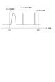
- FIG. 2 is a diagram for explaining the forced regeneration process of the DPF executed by the early post injection and the late post injection according to the embodiment.
- the early post injection as shown in FIG. 2, in the step of injecting fuel into the diesel engine 1, a smaller amount of fuel is injected than in the main injection while the pressure in the combustion chamber 12 immediately after injecting the main fuel is still high. This is the first post injection.
- the exhaust gas temperature can be increased.
- the temperature rising means 4 controlled in the DOC temperature rising control is the intake throttle valve 4 (4B) or the common rail pressure controlling means for controlling the common rail pressure for injecting fuel (not). (Fig.) May be used.
- the temperature raising means 4 includes a fuel injection device 4A, an intake throttle valve 4B, a common rail pressure control means (not shown), an exhaust pipe injection device 4D, an exhaust throttle valve 4C, and an EGR valve 4E. It may be at least one of them.
- the regeneration control device 2 further includes a DPF forced regeneration execution unit 22.
- the DPF forced regeneration execution unit 22 is configured to execute a forced regeneration process that controls the temperature raising means 4 so as to raise the temperature of the DPF 32 to the temperature T2.
- the temperature T2 is a temperature higher than the temperature T1, and is set to, for example, a temperature of 600 ° C. or higher.
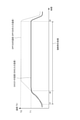
- FIG. 3 is a time chart showing an example of a temperature change when the regeneration control device 2 according to the embodiment executes a forced regeneration process.
- the forced reproduction process is started at time t1 and continues until time t3.
- Late post injection is performed from time t2 when the DOC inlet temperature reaches the temperature T1 to time t3.
- the temperature of the DOC 31 is acquired based on the detection value of the DOC inlet temperature sensor 5 (5A), and the temperature of the DPF 32 is acquired based on the detection value of the DPF inlet temperature sensor 5 (5B).
- the PM accumulated in the filter of the DPF 32 is forcibly burned and removed by executing the forced regeneration process at an appropriate timing.
- the forced regeneration process is classified into at least two types from the viewpoint of triggering the start of execution. That is, there are at least two types of automatic reproduction, that is, automatic reproduction that is automatically executed and manual reproduction that is executed by a manual operation by an operator or the like.
- the automatic regeneration of the DPF 32 is automatically executed by satisfying the predetermined forced regeneration execution condition (automatic regeneration execution condition) regarding the automatic regeneration regardless of whether the vehicle is running or stopped.
- the automatic regeneration execution conditions are, for example, that the estimated value of the PM accumulation amount in the DPF 32 exceeds the specified value (threshold), the operating time of the diesel engine 1 exceeds the specified time (threshold), and the fuel injection amount of the diesel engine 1. It is a condition that the cumulative value of is exceeding the specified amount (threshold).
- the PM deposition amount in the DPF 32 is estimated, for example, by detecting the differential pressure between the upstream and the downstream of the DPF 32 by the DPF differential pressure sensor 6 (6C).
- the engine speed, fuel injection amount, air flow rate, and DPF temperature are detected, and the map is stored in advance in the regeneration control device 2. It is also possible to estimate the PM emission amount from the diesel engine 1 and the PM regeneration amount due to natural regeneration inside the DPF 32, and to estimate the PM accumulation amount by subtracting the PM regeneration amount from the PM emission amount.
- the manual reproduction of the DPF 32 is executed as a forced reproduction execution condition (manual reproduction execution condition) that the operator or the like operates a button, and is basically executed in a state where the vehicle is stopped. ..
- the manual regeneration of the DPF 32 is executed when the PM is accumulated beyond the automatic regeneration condition.
- the condition for executing manual regeneration is that the estimated value of PM deposition exceeds a specified value larger than that for automatic regeneration.
- the manual regeneration of the DPF 32 may include combustion removal performed by a serviceman who performs maintenance when PM is excessively deposited on the DPF 32.
- forced regeneration is performed over a longer period of time than normal manual regeneration.
- the manual regeneration is controlled so that the regeneration temperature is higher than the automatic regeneration.
- the inlet temperature of the DPF 32 is controlled to be 600 to 610 ° C
- the manual regeneration the inlet temperature of the DPF 32 is controlled to be 620 to 630 ° C.
- the temperature raising means 4 used in the forced regeneration process is a fuel injection device 4A and an exhaust pipe injection device 4D that inject fuel into the combustion chamber 12 of the diesel engine 1.
- the forced regeneration process is performed by early post injection by the fuel injection device 4A, late post injection by the fuel injection device 4A, or exhaust pipe injection by the exhaust pipe injection device 4D arranged in the exhaust passage 16 upstream of the DOC 31. Will be executed.
- Late post injection is the second post injection in which fuel is injected at a timing (near bottom dead center) that does not contribute to combustion in the combustion chamber 12 after early post injection.
- TDC top dead center
- BDC bottom dead center
- the main fuel injection is performed after the top dead center, and then early. Post injection is done.
- the late post injection is performed after the early post injection and before the piston reaches the bottom dead center (BDC) from the top dead center (TDC) side.
- the unburned fuel flows out from the combustion chamber 12 to the exhaust passage 16, and the discharged unburned fuel is oxidized in the DOC 31 to raise the temperature of the DPF 32 to the temperature T2. Further, by raising the temperature of the DPF 32 to the temperature T2, the PM deposited on the DPF 32 can be burned.
- the exhaust pipe injection device 4D is arranged between the downstream of the branch position of the EGR pipe 45 and the exhaust turbine 41 of the exhaust turbocharger 7. In some other embodiments, the exhaust pipe injection device 4D may be located between the exhaust turbine 41 and the DOC 31. Further, the fuel injection amount injected from the exhaust pipe injection device 4D to the exhaust passage 16 is controlled by the regeneration control device 2.
- the forced regeneration process of the DPF 32 may be executed after the temperature rise control of the DOC 31 is completed. Further, in some other embodiments, as shown in FIG. 3, the forced regeneration process of the DPF 32 may be executed at a timing independent of the temperature rise control of the DOC 31.
- the temperature of DPF32 is raised to the temperature T1 or higher to activate DPF32.
- This temperature rise may be performed by early post injection under predetermined injection conditions, using the fuel injection device 4A as the temperature raising means 4.
- the intake throttle valve 4B may be used as the temperature raising means 4, and the temperature rise may be executed by controlling the opening degree thereof.
- the common rail pressure control means (not shown) for controlling the common rail pressure for injecting fuel may be used as the temperature raising means 4, and the temperature rise may be executed by controlling the common rail pressure.
- This temperature rise may be performed by using two or more of the fuel injection device 4A, the intake throttle valve 4B, and the common rail pressure control means (not shown) as the temperature raising means 4.
- the temperature of the DPF 32 is raised to the temperature T2 by executing the forced regeneration process of the DPF 32 using the late post injection or the exhaust pipe injection.
- the forced regeneration process of the DPF 32 can be executed by the fuel injection device 4A and the exhaust pipe injection device 4D. Further, when the temperature raising means 4 in the temperature rising control of the DOC 31 is the fuel injection device 4A, the fuel injection device 4A can easily execute the temperature rise control and the forced regeneration process. Further, the fuel injection device 4A is usually provided in the diesel engine 1, and it is not necessary to add another temperature raising means 4, so that the cost can be reduced.
- the DPF forced regeneration execution unit 22 executes the forced regeneration process (automatic regeneration) when it is determined that the forced regeneration execution condition is satisfied, or notifies that the execution of the forced regeneration process is urged, and based on the operator's instruction. Execute forced regeneration processing (manual regeneration).
- the reproduction control device 2 further includes a storage unit 25.
- the storage unit 25 may be a non-volatile memory such as a ROM or a flash memory included in the reproduction control device 2, a volatile memory such as a RAM, or an external storage device connected to the reproduction control device 2. good.
- the storage unit 25 may store information indicating the correspondence between the temperature index of the DOC 31 and the excess air ratio and various maps.
- the reproduction control device 2 further includes a late post injection amount determining unit 23 for determining the late post injection amount.
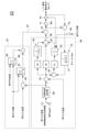
- FIG. 4 is a block diagram schematically showing the configuration of the late post injection amount determining unit 23 according to the embodiment. Hereinafter, the configuration of the late post injection amount determination unit 23 will be described.
- the late post injection amount determination unit 23 determines the late post injection amount (operation amount) so that the inlet temperature of the DPF 32 becomes the target temperature of about 600 ° C. in the forced regeneration process. As shown in FIG. 4, the late post injection amount determination unit 23 is configured to output a feedforward control unit 47 configured to output a feedforward control command value 57 and a feedback control command value 65. It includes a feedback control unit 49 and an adder 51 configured to add a basic injection amount (feedforward control command value 57) and a correction injection amount (feedback control command value 65). Further, the late post injection amount determination unit 23 includes a reset unit 55 that resets the integrated value of the integrator 53 constituting the feedback control unit 49.
- the feedforward control unit 47 is configured to determine a basic injection amount (basic operation amount) of the late post injection amount based on the operating conditions of the internal combustion engine and output it as a feedforward control command value 57.
- the operating conditions of the internal combustion engine are, for example, the temperature difference between the target inlet temperature of the DPF 32 and the inlet temperature of the DOC 31, and the exhaust gas flow rate.
- the feed forward control unit 47 has a purification rate acquisition unit 85 configured to acquire an HC purification rate based on the DOC average temperature and the exhaust gas flow rate, and a temperature difference between the target inlet temperature of the DPF 32 and the inlet temperature of the DOC 31.
- the gas oil amount acquisition unit 87 configured to acquire the required gas oil amount based on the exhaust gas flow rate.
- the purification rate acquisition unit 85 acquires the HC purification rate by using, for example, the HC purification rate map stored in the storage unit 25.
- the gas oil amount acquisition unit 87 acquires the required gas oil amount by using, for example, the gas oil amount map stored in the storage unit 25.
- the feedforward control unit 47 includes a divider 89 in which the HC purification rate acquired by the purification rate acquisition unit 85 and the required gas oil amount acquired by the light oil amount acquisition unit 87 are input.
- the feedforward control unit 47 outputs the required gas oil amount (that is, the feedforward control command value 57) including the HC purification rate via the divider 89.
- the feedback control unit 49 is configured to determine the late post correction injection amount (correction operation amount) with respect to the target temperature of the DPF 32 and output it as the feedback control command value 65.
- the feedback control unit 49 is provided with a target temperature setting unit 59 for setting a target temperature as an initial value at the start of control of the target inlet temperature of the DPF 32 and a target temperature thereafter.
- the target inlet temperature of the DPF 32 and the actually measured inlet temperature of the DPF 32 are input to the adder / subtractor 61, and the deviation between the target inlet temperature and the actually measured inlet temperature is obtained as an output signal of the adder / subtractor 61.
- This output signal is feedback-calculated by the PID calculation unit 63, and the correction injection amount which is the feedback control command value 65 is calculated. In this way, the feedback control unit 49 determines the corrected injection amount of the late post injection amount based on the deviation between the inlet temperature of the DPF 32 and the target temperature.
- the calculation of the proportional element (P) is performed using the proportional gain Kp
- the calculation of the differential element (D) is performed using the differential gain Kd
- the calculation of the integral element (I) is performed by the integral gain. Ki is performed, each calculation result is input to the adder 67, and the feedback control command value 65 is calculated.
- the feedforward control command value 57 and the feedback control command value 65 are input to the adder 51, and the addition command value 69 is output.
- the signal of the addition command value 69 is input to the command saturation unit 71, and the output signal is restricted for the protection of the DPF 32.
- the signal that has passed through the command saturation section 71 is output as a late post fuel injection command signal via the limiting section 81.
- the limiting unit 81 of the late post injection amount determining unit 23 outputs a late post fuel injection command signal that limits the late post injection amount so that it does not exceed the upper limit of the late post injection amount. For example, when the added value of the basic injection amount and the corrected injection amount is equal to or less than the upper limit of the late post injection amount, the late post injection amount determining unit 23 lates the added value of the basic injection amount and the corrected injection amount. It is determined as the post injection amount, and when the added value of the basic injection amount and the corrected injection amount exceeds the upper limit value of the late post injection amount, the late post injection amount is limited to the upper limit value of the late post injection amount.
- the limiting unit 81 is configured to calculate the upper limit of the late post injection amount.
- the limiting unit 81 of the late post injection amount determining unit 23 integrates the integrator 53 of the PID calculation unit 63 for at least a part of the time during which the late post injection amount is limited to the upper limit value of the late post injection amount. Outputs an integration stop signal to freeze. This makes it possible to reduce the overshoot of the late post injection amount after the restriction is lifted.
- the late post injection amount determination unit 23 is based on the adder / subtractor 73 to which the output signal of the command saturation unit 71 or the limit unit 81 and the output signal of the adder 51 are input, and the deviation output by the adder / subtractor 73.
- An automatic compounding PID 75 that performs automatic compounding to the feedback control unit 49 is provided.
- the output signal of the arithmetic element 77 of the automatic preparation PID 75 is input to the adder / subtractor 78 and input to the integrator 53.
- the automatic compounding PID 75 as a wind-up measure (input saturation measure) of the feedback control unit 49
- the PID calculation of the feedback control unit 49 is performed while the command value is limited by the command saturation unit 71. It is prevented that the integrated value continues to be accumulated in the integrator 53 of the unit 63. As a result, the followability when the feedback control target value changes is improved.
- the reset unit 55 is configured to reset the integrated value of the integrator 53 when the exhaust gas flow rate suddenly decreases.
- the exhaust gas flow rate is calculated based on the measured value of the air flow rate acquired from the air flow meter (not shown) and the fuel injection amount command value to the common rail fuel injection device (not shown).
- the feedforward control unit 47 sets the feedforward command value according to the operating conditions in advance by a test on a map or the like, and based on the deviation e between the measured value of the exhaust gas flow rate and the measured value of the DPF inlet target temperature and the DOC inlet temperature. It is configured to calculate and command the basic injection amount (basic operation amount) of the late post injection amount from the map.
- the late post injection amount determining unit 23 includes a limiting unit 81 on the output side of the adder 51. As shown in FIG. 4, the limiting unit 81 may be provided on the output side of the command saturation unit 71, or may be provided on the input side of the command saturation unit 71. The limiting unit 81 is configured to limit the upper limit of the late post injection amount based on the excess air ratio of the exhaust gas flowing into the DOC 31 acquired based on the temperature index of the DOC 31.
- the "air excess ratio” has substantially the same concept as the “air-fuel ratio”, and may be interpreted as the air-fuel ratio.
- the "temperature index of DOC31” is an index indicating the temperature of DOC31, and is, for example, the inlet temperature of DOC31.
- the temperature index of the DOC 31 may be the average temperature of the DOC 31 obtained by averaging the inlet temperature of the DOC 31 and the inlet temperature of the DPF 32 (outlet temperature of the DOC 31), or may be a temperature representative of the temperature of the DOC 31. ..
- the excess air ratio is, for example, a lower limit of the excess air ratio set so that HC slip does not occur.
- the late post injection amount determination unit 23 is configured to determine the upper limit value of the late post injection amount by referring to the information indicating the correspondence between the temperature index of the DOC 31 stored in the storage unit 25 and the excess air rate. May be done.
- the information indicating the correspondence may be a table or a map, or may be an arithmetic expression.
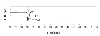
- FIG. 5A is a diagram showing the temporal transition of the rotation speed in the experiment for confirming the HC slip behavior when the load is increased.
- FIG. 5B is a diagram showing a temporal transition of torque in an experiment for confirming HC slip behavior when a load is increased.
- FIG. 5C is a diagram showing the temporal transition of the HC amount in the experiment for confirming the HC slip behavior when the load is increased. These have the same horizontal axis.
- C1 shown by a broken line shows the time transition at the time of loading when the inlet temperature of the DOC 31 is 240 ° C. at a rotation speed of 1000 rpm.
- C2 shown by a solid line shows the time transition at the time of loading when the inlet temperature of the DOC 31 is 270 ° C. at a rotation speed of 1000 rpm.
- C3 shown by the alternate long and short dash line shows the time transition at the time of loading when the inlet temperature of the DOC 31 is 300 ° C. at a rotation speed of 1000 rpm.
- Information indicating the correspondence relationship is set based on the knowledge of such experimental results.
- the excess air rate when the temperature index of DOC31 is higher than the first temperature at the second temperature is smaller than the excess air rate when the temperature index of DOC31 is the first temperature. preferable.
- FIG. 6 is a diagram showing an example of information indicating a correspondence relationship stored in the reproduction control device 2 according to the embodiment.
- the information indicating the correspondence relationship may be a table showing the relationship between the DOC inlet temperature as the temperature index of the DOC 31 and the lower limit value of the exhaust air excess rate as the air excess rate. ..
- the lower limit of the exhaust air excess rate is set to A1.
- the lower limit of the exhaust air excess rate is set to A2.
- A3 is set when the DOC inlet temperature is 270 ° C
- A4 is set when the DOC inlet temperature is 280 ° C
- A5 is set when the DOC inlet temperature is 300 ° C
- the DOC inlet is set.
- A6 is set.
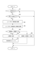
- FIG. 7 is a flowchart for explaining an example of the process executed by the reproduction control device 2 according to the embodiment.
- the processing related to the operation of the late post injection amount determination unit 23 will be described.
- the reproduction control device 2 determines whether or not the forced reproduction process is being executed (step S1). When it is determined that the forced reproduction process is not being executed (step S1; No), the reproduction control device 2 skips the subsequent processes and returns. When it is determined that the forced regeneration process is being executed (step S1; Yes), the regeneration control device 2 determines whether or not the inlet temperature of the DOC 31 is equal to or higher than the predetermined temperature T1 (step S2). In step S2, the regeneration control device 2 may compare the DOC temperature index with the predetermined temperature T1 instead of the inlet temperature of the DOC 31.
- step S3 When it is determined that the inlet temperature of the DOC 31 is not equal to or higher than the predetermined temperature T1 (step S2; No), the reproduction control device 2 skips the subsequent processing and returns.
- the late post injection amount determining unit 23 of the reproduction control device 2 determines the late post injection amount (that is, the basic injection amount and the correction injection amount). The added value) is calculated (step S3).
- the late post injection amount determination unit 23 of the reproduction control device 2 has an upper limit of the late post injection amount based on the excess air ratio of the exhaust gas flowing into the DOC 31 acquired based on the temperature index of the DOC 31 (for example, the inlet temperature of the DOC 31). Calculate the value (step S4).
- the late post injection amount determination unit 23 of the reproduction control device 2 determines whether or not the calculated value (that is, the added value) exceeds the upper limit value (step S5).
- the late post injection amount determination unit 23 determines the late post injection amount as the upper limit value (step S6). Freezes the integration operation of the PID calculation unit 63 (step S7). When it is determined that the calculated value (that is, the added value) does not exceed the upper limit value (step S5; No), the late post injection amount determining unit 23 determines the late post injection amount as the calculated value (that is, the added value) (that is, the added value). Step S8).
- Steps S5 to S8 are realized by limiting the late post injection amount of the limiting unit 81.
- the reproduction control device 2 performs late post injection based on the determined late post injection amount. It should be noted that the calculated value (that is, the added value) and the upper limit value of the late post injection amount need to be calculated so as to change from moment to moment. Therefore, these processes return to step S1 again, and the calculation is repeated.
- FIG. 8 is a diagram for explaining the experimental results of Examples and Comparative Examples in comparison with each other.
- the regeneration control device 2 according to the above embodiment is used to acquire the HC slip maximum concentration and the forced regeneration processing time of the DPF 32 for each of the four operation patterns (operation patterns 1 to 4).
- the inlet temperature of the DOC 31 at the maximum HC slip is changed.
- the inlet temperature of the DOC 31 at the maximum HC slip is the same, but the rotation speed and the way of increasing the load are changed.
- the comparative example shows the result when the limit based on the upper limit value of the late post injection amount is not applied, and the embodiment shows the result when the limit is applied based on the upper limit value of the late post injection amount.
- the HC slip maximum concentration is significantly reduced as compared with the comparative example.
- the forced regeneration time did not increase as compared with the comparative example, and there was no adverse effect. From these experimental results, it can be seen that the limitation based on the upper limit of the late post injection amount is meaningful.
- the present disclosure is not limited to the above-mentioned embodiment, and includes a form in which the above-mentioned embodiment is modified and a form in which a plurality of embodiments are appropriately combined.
- the reproduction control device (2) is The exhaust gas treatment device (3) of the diesel engine (1) including the diesel oxidation catalyst (DOC31) arranged in the exhaust passage (16) of the internal combustion engine and the diesel particulate filter (DPF32) arranged downstream of the DOC (31). ), The regeneration control device (2) for controlling the execution of forced regeneration that removes the exhaust fine particles (PM) accumulated on the DPF (32) by raising the temperature of the DPF (32).
- a late post injection amount determination unit (23) for determining the late post injection amount is provided.
- the late post injection amount determining unit (23) has an upper limit of the late post injection amount based on the excess air ratio of the exhaust gas flowing into the DOC (31) acquired based on the temperature index of the DOC (31). It is configured to determine the value.
- the upper limit of the late post injection amount is determined based on the excess air ratio of the exhaust gas flowing into the DOC (31) acquired based on the temperature index of the DOC (31). Therefore, it is possible to realize fine control so as not to excessively suppress the late post injection amount while reducing the generation of white smoke. As a result, it does not have an adverse effect such as an increase in DPF regeneration time. Further, since the excess air ratio of the exhaust gas is used in determining the upper limit value of the late post injection amount, more accurate control can be realized as compared with the case of using the excess air ratio of the supply air.
- a storage unit (25) for storing information indicating the correspondence between the temperature index of the DOC (31) and the excess air ratio is provided.
- the late post injection amount determination unit (23) is configured to determine an upper limit value of the late post injection amount with reference to the information indicating the correspondence relationship.
- the excess air ratio when the temperature index of the DOC (31) is a second temperature higher than the first temperature is the said when the temperature index of the DOC is the first temperature. Equivalent or smaller than the excess air rate.
- the injection amount of unburned fuel that can be oxidized by DOC (31) increases as the temperature index of DOC (31) increases.
- the excess air ratio when the temperature index of the DOC (31) is the second temperature higher than the first temperature is the air when the temperature index of the DOC (31) is the first temperature. Equivalent or smaller than the excess rate.
- the upper limit of the late post injection amount is determined using such an excess air ratio. In this case, the upper limit of the late post injection amount can be determined to be an appropriate value according to the injection amount of the unburned fuel that can be oxidized by the DOC (31).
- the late post injection amount determination unit (23) A feedforward control unit (47) for determining the basic injection amount of the late post injection amount based on the operating conditions of the internal combustion engine, and A feedback control unit (49) for determining the corrected injection amount of the late post injection amount based on the deviation between the inlet temperature and the target temperature of the DPF (32), Including
- the late post injection amount determining unit (23) uses the added value as the late post injection amount.
- the late post injection amount is limited to the upper limit of the late post injection amount.
- the feedback control unit (49) has a PID calculation unit (63).
- the late post injection amount determination unit (23) freezes the integration operation of the PID calculation unit (63) at least for a part of the time during which the late post injection amount is limited to the upper limit value of the late post injection amount. Let me.
Landscapes
- Engineering & Computer Science (AREA)
- Chemical & Material Sciences (AREA)
- Combustion & Propulsion (AREA)
- Mechanical Engineering (AREA)
- General Engineering & Computer Science (AREA)
- Chemical Kinetics & Catalysis (AREA)
- Materials Engineering (AREA)
- Health & Medical Sciences (AREA)
- Toxicology (AREA)
- Processes For Solid Components From Exhaust (AREA)
- Electrical Control Of Air Or Fuel Supplied To Internal-Combustion Engine (AREA)
- Exhaust Gas After Treatment (AREA)
Abstract
再生制御装置は、内燃機関の排気通路に配置されるディーゼル酸化触媒(DOC)及びDOCの下流に配置されるディーゼルパティキュレートフィルタ(DPF)を備えるディーゼルエンジンの排ガス処理装置において、DPFの昇温によりDPFに堆積する排気微粒子(PM)を除去する強制再生の実行を制御するための再生制御装置である。再生制御装置は、レイトポスト噴射量を決定するレイトポスト噴射量決定部を備える。レイトポスト噴射量決定部は、DOCの温度指標に基づいて取得されるDOCに流入する排気の空気過剰率に基づいて、レイトポスト噴射量の上限値を決定するように構成される。
Description
本開示は、ディーゼルエンジンの排気通路に配置されるDOC及びDPFを有する排ガス処理装置を再生するための再生制御装置に関する。
本願は、2020年9月7日に日本国特許庁に出願された特願2020-149765号に基づき優先権を主張し、その内容をここに援用する。
本願は、2020年9月7日に日本国特許庁に出願された特願2020-149765号に基づき優先権を主張し、その内容をここに援用する。
ディーゼルエンジンには、排気通路に配置されるDOC(ディーゼル酸化触媒)と、該DOCの下流に配置されるDPF(ディーゼルパティキュレートフィルタ)とからなる排ガス処理装置が搭載される。DPFは、ディーゼルエンジンから排出される排ガス中に含まれるPM(粒子状物質)を捕集するための装置である。
DPFは、一般にセラミック等をハニカム状モノリスに成形して隣り合う通気孔が入口側と出口側で交互に閉じられて排ガスがろ過壁を通過するように構成され、このろ過壁によってPMが除去される。DPFには、触媒が担持されるものもある。DOCは、DPFと同様、一般にセラミック等をハニカム状モノリスに成形して構成され、その内側表面に酸化触媒を担持してなる。
DPFにPMが堆積していくとやがて目詰まりが発生し、DPFのPM捕集能力が低下するだけでなく、排圧が上昇して燃費にも悪影響を及ぼす。このため、PM堆積量が規定量に達した場合又はエンジン運転時間が規定時間を経過した場合に、DPFに堆積したPMを除去する強制再生を行う必要がある。DPFの強制再生は、排ガス温度を上昇させて、DPFを強制的に昇温させることによって行われる。例えば、燃料噴射タイミングの遅延、ポスト噴射、吸気又は排気絞り等によって、この昇温が実行される。
DPFの強制再生の実行において、未燃燃料の噴射量(ポスト噴射量)がDOCで酸化可能な量より多い場合、未燃燃料が酸化されないまま排気され、白煙が発生する場合がある。このような白煙の発生を抑制するための手法が提案されている。例えば、特許文献1には、空燃比と、大気圧と、DOC温度と回転数による触媒反応と、のそれぞれから求まる噴射量のうち最小値を噴射量の上限値とするように制御することが開示されている。
しかし、実際に負荷変動時に白煙が発生し得るのは、空燃比が低い場合である。そのため、特許文献1に開示されている制御方法では、結局のところ空燃比だけで噴射量の上限値が決まり、DOC温度とは無関係に噴射量の上限値が決定される。このような方法では、DOC温度がどのような温度であっても白煙が発生しないように噴射量を制限しなければならない。したがって、どのような温度でも白煙が発生しないように少なめの噴射量となるように設定しておかざるをえず噴射量を過度に抑制するように制御が実行され、DPF再生時間が増加する虞がある。
上述の事情に鑑みて、本開示は、筒内燃焼に寄与しないタイミングで噴射するレイトポスト噴射量を過度に抑制しないように細やかな制御を実現し、DPF再生時間の増大無く白煙の発生を低減することを目的とする。
本開示に係る再生制御装置は、
内燃機関の排気通路に配置されるディーゼル酸化触媒(DOC)及び前記DOCの下流に配置されるディーゼルパティキュレートフィルタ(DPF)を備えるディーゼルエンジンの排ガス処理装置において、前記DPFの昇温により前記DPFに堆積する排気微粒子(PM)を除去する強制再生の実行を制御するための再生制御装置であって、
レイトポスト噴射量を決定するレイトポスト噴射量決定部を備え、
前記レイトポスト噴射量決定部は、前記DOCの温度指標に基づいて取得される前記DOCに流入する排気の空気過剰率に基づいて、前記レイトポスト噴射量の上限値を決定するように構成される。
内燃機関の排気通路に配置されるディーゼル酸化触媒(DOC)及び前記DOCの下流に配置されるディーゼルパティキュレートフィルタ(DPF)を備えるディーゼルエンジンの排ガス処理装置において、前記DPFの昇温により前記DPFに堆積する排気微粒子(PM)を除去する強制再生の実行を制御するための再生制御装置であって、
レイトポスト噴射量を決定するレイトポスト噴射量決定部を備え、
前記レイトポスト噴射量決定部は、前記DOCの温度指標に基づいて取得される前記DOCに流入する排気の空気過剰率に基づいて、前記レイトポスト噴射量の上限値を決定するように構成される。
本開示によれば、レイトポスト噴射量を過度に抑制しないように細やかな制御を実現し、DPF再生時間の増大無く白煙の発生を低減できる。
以下、添付図面を参照して幾つかの実施形態について説明する。ただし、実施形態として記載されている又は図面に示されている構成部品の寸法、材質、形状、その相対的配置等は、発明の範囲をこれに限定する趣旨ではなく、単なる説明例にすぎない。
例えば、「ある方向に」、「ある方向に沿って」、「平行」、「直交」、「中心」、「同心」或いは「同軸」等の相対的或いは絶対的な配置を表す表現は、厳密にそのような配置を表すのみならず、公差、若しくは、同じ機能が得られる程度の角度や距離をもって相対的に変位している状態も表すものとする。
例えば、「同一」、「等しい」及び「均質」等の物事が等しい状態であることを表す表現は、厳密に等しい状態を表すのみならず、公差、若しくは、同じ機能が得られる程度の差が存在している状態も表すものとする。
例えば、四角形状や円筒形状等の形状を表す表現は、幾何学的に厳密な意味での四角形状や円筒形状等の形状を表すのみならず、同じ効果が得られる範囲で、凹凸部や面取り部等を含む形状も表すものとする。
一方、一の構成要素を「備える」、「具える」、「具備する」、「含む」、又は、「有する」という表現は、他の構成要素の存在を除外する排他的な表現ではない。
例えば、「ある方向に」、「ある方向に沿って」、「平行」、「直交」、「中心」、「同心」或いは「同軸」等の相対的或いは絶対的な配置を表す表現は、厳密にそのような配置を表すのみならず、公差、若しくは、同じ機能が得られる程度の角度や距離をもって相対的に変位している状態も表すものとする。
例えば、「同一」、「等しい」及び「均質」等の物事が等しい状態であることを表す表現は、厳密に等しい状態を表すのみならず、公差、若しくは、同じ機能が得られる程度の差が存在している状態も表すものとする。
例えば、四角形状や円筒形状等の形状を表す表現は、幾何学的に厳密な意味での四角形状や円筒形状等の形状を表すのみならず、同じ効果が得られる範囲で、凹凸部や面取り部等を含む形状も表すものとする。
一方、一の構成要素を「備える」、「具える」、「具備する」、「含む」、又は、「有する」という表現は、他の構成要素の存在を除外する排他的な表現ではない。
(ディーゼルエンジンの全体構成)
図1は、本発明の一実施形態に係る再生制御装置2を有するディーゼルエンジン1の全体構成を例示する概略図である。再生制御装置2は、ディーゼルエンジン1の排気通路16に配置される排ガス処理装置3の再生(すなわちDOC31の回復処理及びDPF32の強制再生処理)を、排ガス処理装置3の昇温手段4(4A、4B、4C、4D、4E)を制御することにより実行するものである。
図1は、本発明の一実施形態に係る再生制御装置2を有するディーゼルエンジン1の全体構成を例示する概略図である。再生制御装置2は、ディーゼルエンジン1の排気通路16に配置される排ガス処理装置3の再生(すなわちDOC31の回復処理及びDPF32の強制再生処理)を、排ガス処理装置3の昇温手段4(4A、4B、4C、4D、4E)を制御することにより実行するものである。
図1に示すように、ディーゼルエンジン1は、再生制御装置2(ECU9)及び排ガス処理装置3に加えて、エンジン本体11と、吸気通路13と、排気通路16と、排気ターボ過給機7と、EGR装置8と、を備えている。なお、図1に示される一実施形態では、再生制御装置2は、ECU(Engine Control Unit)9であり、ECU9の備える機能(プログラムや回路)の一つとして実装されている。しかし、他の幾つかの実施形態では、ディーゼルエンジン1をコントロールするECU9とは別に、プロセッサを備える他の電子制御ユニットとして再生制御装置2が構成されてもよい。
ECU9は、ディーゼルエンジン1をコントロールする電子制御ユニットである。例えば、ECU9は、プロセッサを含む中央処理装置(CPU)、ランダムアクセスメモリ(RAM)、リードオンリメモリ(ROM)、及びI/Oインターフェイスなどからなるマイクロコンピュータとして構成されてもよい。
エンジン本体11には、吸気通路13と排気通路16とが接続されている。吸気通路13は、ディーゼルエンジン1の外部の空気(吸気)をエンジン本体11に形成される燃焼室12に供給するための通路である。排気通路16は、燃焼室12からの燃焼ガス(排ガス)をディーゼルエンジン1の外部に排出するための通路である。
排気通路16には、DOC31の直上流位置に排気スロットルバルブ4(4C)が設けられている。排気スロットルバルブ4(4C)は、再生制御装置2(ECU9)によって、その開度が制御される。
ディーゼルエンジン1には、燃焼室12に高圧燃料を噴射するための燃料噴射装置4(4A)が配置されている。燃料噴射装置4Aは、高圧燃料が蓄圧されたコモンレール(不図示)に接続されるとともに、ECU9によって、その噴射タイミングおよび燃料噴射量が制御されるようになっている。そして、燃焼室12に噴射された高圧燃料は、吸気通路13を通って供給される吸気と混合された後、燃焼室12内で燃焼され、排気通路16を通ってディーゼルエンジン1の外部に排出される。
吸気通路13及び排気通路16には排気ターボ過給機7が設けられている。この排気ターボ過給機7は、排気通路16に配置されている排気タービン41と、吸気通路13に配置されているコンプレッサ42とを有しており、排気タービン41とコンプレッサ42とはシャフト43によって同軸で結合されている。そして、排気通路16を通過する排ガスにより排気タービン41が回転駆動されると、シャフト43によって同軸で結合されたコンプレッサ42も同じように回転駆動されるようになっている。
吸気通路13にはインタークーラ(不図示)及び吸気スロットルバルブ4(4B)が設けられている。そして、コンプレッサ42から吐出された圧縮吸気は、インタークーラ(不図示)で冷却された後、吸気スロットルバルブ4(4B)で吸気流量が制御され、その後、ディーゼルエンジン1の本体(不図示のシリンダヘッド)に設けられる吸気ポート14を介してディーゼルエンジン1の各シリンダ内の燃焼室12に流入する。なお、吸気スロットルバルブ4(4B)も、再生制御装置2(ECU9)によって、その開度が制御される。
ディーゼルエンジン1はEGR装置8を備えている。すなわち、吸気通路13と排気通路16とがEGR管45を介して連結されており、排気通路16を流れる排ガスの一部を吸気通路13に再循環することが可能に構成されている。
排気ポート17の直下流位置にEGR管45の一端が接続され、排気通路16からEGR管45が分岐している。また、EGR管45のもう一方の端部は、吸気スロットルバルブ4(4B)の下流側に位置している吸気マニホールド15(吸気通路13)に接続している。また、EGR管45にはEGRバルブ4(4E)が配置されている。このEGRバルブ4(4E)を制御することにより、ディーゼルエンジン1から排出された排ガスの一部が、EGR管45を通ってディーゼルエンジン1を再循環するようになっている。なお、EGRバルブ4(4E)も、再生制御装置2(ECU9)によって、その開度が制御される。
上述したように、ディーゼルエンジン1では、エンジン本体11(燃焼室12)から排出された排ガスは、上述した排気タービン41を駆動した後、排気通路16に設けられた上記の排ガス処理装置3に流入するよう構成されている。
排ガス処理装置3は、ディーゼルエンジン1の排気通路16に配置されるDOC31(ディーゼル酸化触媒)と、DOC31の下流の排気通路16に配置されるDPF32(ディーゼルパティキュレートフィルタ)とを備える。DOC31は、排ガス中の未燃燃料(HC)や一酸化炭素(CO)を酸化除去するとともに、排ガス中の一酸化窒素(NO)を酸化して二酸化窒素(NO2)を生成する機能を有する装置である。また、DOC31では、DOC31内に噴射された燃料の酸化熱によって通過する排ガスを昇温し、DPF32の入口温度を昇温する。
DPF32は、排ガス中に含まれるススなどのPM(粒子状物質)をフィルタで捕集し、排ガスから除去する装置である。つまり、排ガス処理装置3に流入した排ガスは、排ガス処理装置3の内部において、DOC31を通過し、次に、DPF32を通過する。この通過の際に、DOC31において、排ガス中に含まれる未燃燃料(HC)や一酸化炭素(CO)が酸化除去される。また、DPF32によって排ガス中のPM(粒子状物質)が捕集され、排ガス中に含まれるPMが除去される。その後、排ガスはディーゼルエンジン1の外部に排出される。
このように排ガス処理装置3を通過する排ガスが、ディーゼルエンジン1の運転負荷が低く、排ガス温度が低い状態が続く場合には、DOC31の上流側端面に未燃燃料等のSOF分やスートなどが付着していき、DOC31の閉塞が除々に進行する。DOC31の閉塞をもたらす付着物は、DOC31を昇温することによって除去可能である。そこで、再生制御装置2は、昇温手段4(後述)を制御することによって、昇温要状態にあるDOC31の昇温を行う。
再生制御装置2は、排ガスや排ガス処理装置3の状態を、排気通路16に設置される各種センサ類からの検出値に基づいて監視する。例えば、図1に示すように、DOC31の入口にはDOC入口温度センサ5(5A)が設けられ、DOC31に流入する排ガス温度が検出される。DPF32の入口(DOC31とDPF32との間)にはDPF入口温度センサ5(5B)が設けられ、DPF32の出口にはDPF出口温度センサ5(5C)が設けられる。また、DPF32の入口にはDPF入口圧力センサ6(6A)が設けられ、DPF32の出口にはDPF出口圧力センサ6(6B)が設けられる。さらに、DPF32には、DPF32の入口と出口の間の差圧を検出するためのDPF差圧センサ6(6C)が設けられる。これらの温度センサ5及び圧力センサ6の検出値は再生制御装置2に入力され、後述するDOC昇温制御及びDPF強制再生処理の実行において使用される。
(DOC昇温制御)
DOC昇温実行部21は、DOC31の昇温要状態が検知された場合に、昇温手段4を制御して、DOC31を回復させるための昇温を実行する。この処理は、温度T1(図3参照)までDOC31を昇温するように昇温手段4(後述)を制御する処理である。温度T1は、DOC31が活性化する程度の温度であり、例えば250℃に設定される。なお、昇温処理は、二段階の昇温を実行する処理であってもよい。二段階の昇温では、例えば、温度T1を所定時間維持した後に、さらに温度T1よりも高い温度(例えば400℃等のDOC31の上流側端面の付着物を燃焼させるための温度)までDOC31を昇温させてその温度を維持する。
DOC昇温実行部21は、DOC31の昇温要状態が検知された場合に、昇温手段4を制御して、DOC31を回復させるための昇温を実行する。この処理は、温度T1(図3参照)までDOC31を昇温するように昇温手段4(後述)を制御する処理である。温度T1は、DOC31が活性化する程度の温度であり、例えば250℃に設定される。なお、昇温処理は、二段階の昇温を実行する処理であってもよい。二段階の昇温では、例えば、温度T1を所定時間維持した後に、さらに温度T1よりも高い温度(例えば400℃等のDOC31の上流側端面の付着物を燃焼させるための温度)までDOC31を昇温させてその温度を維持する。
また、DOC昇温制御において制御される昇温手段4は、例えば、ディーゼルエンジン1の燃焼室12に燃料を噴射する燃料噴射装置4A(図1参照)である。そして、DOC昇温処理は、燃料噴射装置4(4A)によるアーリーポスト噴射のタイミングや噴射量を変更することにより実行される。図2は、一実施形態に係るアーリーポスト噴射とレイトポスト噴射により実行されるDPFの強制再生処理を説明するための図である。アーリーポスト噴射は、図2に示すように、ディーゼルエンジン1に燃料を噴射する工程において、メイン燃料を噴射した直後の燃焼室12内の圧力がまだ高い状態でメイン噴射より少量の燃料を噴射する1回目のポスト噴射である。かかるアーリーポスト噴射の条件を適切に変更することによれば、排ガス温度を高めることが出来る。
なお、他の幾つかの実施形態では、DOC昇温制御において制御される昇温手段4は、吸気スロットルバルブ4(4B)、または、燃料を噴射するコモンレール圧を制御するコモンレール圧制御手段(不図示)であってもよい。その他の幾つかの実施形態では、昇温手段4は、燃料噴射装置4A、吸気スロットルバルブ4B、及びコモンレール圧制御手段(不図示)、排気管噴射装置4D、排気スロットルバルブ4C、及びEGRバルブ4Eのうちの少なくとも1つであってもよい。
(DPF強制再生処理)
図1に示すように、再生制御装置2は、DPF強制再生実行部22をさらに備えている。DPF強制再生実行部22は、温度T2までDPF32を昇温するように昇温手段4を制御する強制再生処理を実行するように構成される。温度T2は、温度T1よりも高い温度であり、例えば600℃以上の温度に設定される。
図1に示すように、再生制御装置2は、DPF強制再生実行部22をさらに備えている。DPF強制再生実行部22は、温度T2までDPF32を昇温するように昇温手段4を制御する強制再生処理を実行するように構成される。温度T2は、温度T1よりも高い温度であり、例えば600℃以上の温度に設定される。
図3は、一実施形態に係る再生制御装置2が強制再生処理を実行した場合の温度変化の一例を示すタイムチャートである。この例では、時刻t1に強制再生処理が開始され、時刻t3まで継続している。DOC入口温度が温度T1に達した時刻t2から時刻t3までレイトポスト噴射が行われる。なお、DOC31の温度はDOC入口温度センサ5(5A)の検出値に基づいて取得され、DPF32の温度は、DPF入口温度センサ5(5B)の検出値に基づいて取得される。
DPF32の強制再生について説明すると、上述の通り、排ガス処理装置3の内部を排ガスが通過する際には、排ガス中に含まれるPM(粒子状物質)はDPF32によって捕集される。このDPF32で捕集されたPMは、運転中のエンジン本体11(燃焼室12)から排出される排ガスが高温の場合には、高温の排ガスによって燃焼し、自然に除去される(自然再生)。しかし、自然再生によって除去されないPMはDPF32のフィルタに堆積していくことになる。そして、PMの堆積が過度に進行すると、PM捕集能力の低下、エンジン出力の低下などを招来する。
このため、DPF32を備える排ガス処理装置3においては、適切なタイミングで強制再生処理を実行することで、DPF32のフィルタに堆積しているPMを強制的に燃焼させて除去している。そして、この強制再生処理は、その実行開始のトリガの観点から、少なくとも2種類に分類される。すなわち、自動的に実行される自動再生と、操作者等の手動操作によって実行される手動再生、の少なくとも2種類となる。
DPF32の自動再生は車両の走行・停止に関わらず、自動再生に関する所定の強制再生実行条件(自動再生実行条件)を満たすことで自動的に実行される。この自動再生実行条件は、例えば、DPF32におけるPM堆積量の推定値が規定値(閾値)を超えること、ディーゼルエンジン1の運転時間が規定時間(閾値)を超えること、ディーゼルエンジン1の燃料噴射量の累計値が規定量(閾値)を超えること等の条件である。
なお、DPF32におけるPM堆積量の推定は、例えばDPF32の上流と下流とにおける差圧をDPF差圧センサ6(6C)によって検出することによって行われる。なお、エンジン回転数、燃料噴射量、空気流量、DPF温度(例えば、DPF出口温度センサ5(5C)の検出値など)を検出し、再生制御装置2に予め記憶されているマップに基づいて、ディーゼルエンジン1からのPM排出量とDPF32の内部での自然再生によるPM再生量とを推定し、PM排出量からPM再生量を差し引くことでPM堆積量を推定することも可能である。
一方、DPF32の手動再生は、操作者等のボタン操作等がされることを強制再生実行条件(手動再生実行条件)として実行されるものであり、基本的に車両が停止した状態で実行される。DPF32の手動再生は、自動再生条件を超えてPMが堆積している場合に実行される。例えば、手動再生実行条件は、PM堆積量の推定値が、自動再生よりも大きい規定値を超えることが条件とされる。
また、DPF32の手動再生には、DPF32にPMが過度に堆積した時に、メンテナンスを行うサービスマンによって行われる燃焼除去が含まれてもよい。この場合、DPF32の過昇温を避けるため、通常の手動再生よりも長時間をかけて強制再生が行われる。そして、強制再生の実行温度においても両者に違いがあり、手動再生の方が自動再生よりも再生温度が高くなるように制御される。一例としては、自動再生ではDPF32の入口温度が600~610℃となるように制御されるのに対し、手動再生ではDPF32の入口温度が620~630℃となるように制御される。
上記のDPF強制再生実行部22による強制再生処理について詳述する。幾つかの実施形態では、強制再生処理において使用される昇温手段4は、ディーゼルエンジン1の燃焼室12に燃料を噴射する燃料噴射装置4Aと排気管噴射装置4Dである。この場合、強制再生処理は、燃料噴射装置4Aによるアーリーポスト噴射と、燃料噴射装置4Aによるレイトポスト噴射又はDOC31の上流の排気通路16に配置される排気管噴射装置4Dによる排気管噴射と、により実行される。
レイトポスト噴射は、アーリーポスト噴射の後の燃焼室12内の燃焼に寄与しないタイミング(下死点近傍)で燃料を噴射する2回目のポスト噴射である。図2に示す一例では、エンジン本体11に設けられるピストンが上死点(TDC)から下死点(BDC)に移動する間において、上死点を過ぎたところでメイン燃料噴射がなされ、その後にアーリーポスト噴射がなされている。そして、アーリーポスト噴射後であって、ピストンが上死点(TDC)側から下死点(BDC)に到達する前に、レイトポスト噴射がなされている。このレイトポスト噴射によって、燃焼室12から排気通路16へ未燃燃料を流出させ、排出された未燃燃料がDOC31において酸化することでDPF32を温度T2まで昇温している。また、温度T2までDPF32を昇温することで、DPF32に堆積したPMを燃焼させることができる。
なお、図1では、EGR管45の分岐位置下流と排気ターボ過給機7の排気タービン41との間に、排気管噴射装置4Dが配置されている。他の幾つかの実施形態では、排気管噴射装置4Dは、排気タービン41とDOC31の間にあってもよい。また、排気管噴射装置4Dから排気通路16へ噴射する燃料噴射量は、再生制御装置2によって制御される。
DPF32の強制再生処理は、幾つかの実施形態では、DOC31の昇温制御の完了後に実行されてもよい。また、他の幾つかの実施形態では、図3に示すように、DOC31の昇温制御とは独立したタイミングでDPF32の強制再生処理が実行されてもよい。
この場合、DPF32の強制再生処理において、まずは、DPF32を温度T1以上に昇温し、DPF32を活性化する。この昇温は、燃料噴射装置4Aを昇温手段4とし、所定の噴射条件によるアーリーポスト噴射によって実行されてもよい。また、吸気スロットルバルブ4Bを昇温手段4とし、その開度を制御することでこの昇温を実行してもよい。また、燃料を噴射するコモンレール圧を制御するコモンレール圧制御手段(不図示)を昇温手段4とし、コモンレール圧を制御することでこの昇温を実行してもよい。燃料噴射装置4A、吸気スロットルバルブ4B、コモンレール圧制御手段(不図示)のうちの2つ以上を昇温手段4としてこの昇温を実行してもよい。その後、レイトポスト噴射や排気管噴射を用いたDPF32の強制再生処理を実行することで、DPF32が温度T2まで昇温される。
上記の構成によれば、燃料噴射装置4Aや排気管噴射装置4Dによって、DPF32の強制再生処理を実行することができる。また、DOC31の昇温制御における昇温手段4が燃料噴射装置4Aである場合には、燃料噴射装置4Aによって、昇温制御と強制再生処理を容易に実行することができる。また、燃料噴射装置4Aはディーゼルエンジン1が通常備えており、他の昇温手段4を追加する必要はなく、コストの低減を図ることができる。
DPF強制再生実行部22は、強制再生実行条件を満たすと判定した場合に強制再生処理(自動再生)を実行したり、強制再生処理の実行を促す旨の報知を行い、オペレータの指示に基づいて強制再生処理(手動再生)を実行したりする。
また、幾つかの実施形態では、図1に示すように、再生制御装置2は、記憶部25をさらに備える。記憶部25は、再生制御装置2が備えるROM、フラッシュメモリなどの不揮発性メモリや、RAMなどの揮発性メモリであっても良いし、再生制御装置2に接続された外部記憶装置であっても良い。記憶部25には、例えば、後述するように、DOC31の温度指標と空気過剰率との対応関係を示す情報や各種マップを記憶させてもよい。
(レイトポスト噴射量決定部の構成)
図1に示すように、再生制御装置2は、レイトポスト噴射量を決定するレイトポスト噴射量決定部23をさらに備えている。図4は、一実施形態に係るレイトポスト噴射量決定部23の構成を概略的に示すブロック図である。以下、レイトポスト噴射量決定部23の構成について説明する。
図1に示すように、再生制御装置2は、レイトポスト噴射量を決定するレイトポスト噴射量決定部23をさらに備えている。図4は、一実施形態に係るレイトポスト噴射量決定部23の構成を概略的に示すブロック図である。以下、レイトポスト噴射量決定部23の構成について説明する。
レイトポスト噴射量決定部23は、強制再生処理においてDPF32の入口温度が約600℃の目標温度になるようにレイトポスト噴射量(操作量)を決定する。図4に示すように、レイトポスト噴射量決定部23は、フィードフォワード制御指令値57を出力するように構成されたフィードフォワード制御部47と、フィードバック制御指令値65を出力するように構成されたフィードバック制御部49と、基本噴射量(フィードフォワード制御指令値57)と補正噴射量(フィードバック制御指令値65)とを加算するように構成された加算器51と、を含む。また、レイトポスト噴射量決定部23は、フィードバック制御部49を構成する積分器53の積分値をリセットするリセット部55を備える。
フィードフォワード制御部47は、内燃機関の運転条件に基づいてレイトポスト噴射量の基本噴射量(基本操作量)を決定し、それをフィードフォワード制御指令値57として出力するように構成される。内燃機関の運転条件は、例えば、図4に示すように、DPF32の目標入口温度とDOC31の入口温度との温度差、及び排ガス流量である。
フィードフォワード制御部47は、DOC平均温度と排ガス流量とに基づいてHC浄化率を取得するように構成された浄化率取得部85と、DPF32の目標入口温度とDOC31の入口温度との温度差、及び排ガス流量に基づいて必要軽油量を取得するように構成された軽油量取得部87とを含む。浄化率取得部85は、例えば、記憶部25に記憶されているHC浄化率マップを用いて、HC浄化率を取得する。軽油量取得部87は、例えば、記憶部25に記憶されている軽油量マップを用いて、必要軽油量を取得する。
また、フィードフォワード制御部47は、浄化率取得部85が取得したHC浄化率と、軽油量取得部87が取得した必要軽油量とが入力される除算器89を含む。フィードフォワード制御部47は、除算器89を介してHC浄化率を加味した必要軽油量(すなわちフィードフォワード制御指令値57)を出力する。
フィードバック制御部49は、DPF32の目標温度に対するレイトポスト補正噴射量(補正操作量)を決定し、それをフィードバック制御指令値65として出力するように構成される。フィードバック制御部49には、DPF32の目標入口温度を制御開始時の初期値の目標温度と、その後の目標温度を設定する目標温度設定部59が設けられる。
フィードバック制御部49において、DPF32の目標入口温度と実測したDPF32の入口温度とが加減算器61に入力され、目標入口温度と実測入口温度との偏差を加減算器61の出力信号として得られる。この出力信号がPID演算部63でフィードバック演算され、フィードバック制御指令値65である補正噴射量が算出される。このように、フィードバック制御部49は、DPF32の入口温度と目標温度との偏差に基づいてレイトポスト噴射量の補正噴射量を決定する。
PID演算部63では、比例要素(P)の演算が比例ゲインKpを用いて行われ、微分要素(D)の演算が微分ゲインKdを用いて行われ、積分要素(I)の演算が積分ゲインKi行われて、それぞれの演算結果が、加算器67に入力されて、フィードバック制御指令値65が算出される。
そして、フィードフォワード制御指令値57と、フィードバック制御指令値65とが加算器51に入力されて、加算指令値69が出力される。この加算指令値69の信号は指令飽和部71に入力されてDPF32の保護のために出力信号に制限が掛けられる。そして指令飽和部71を通過した信号は、制限部81を介してレイトポスト燃料噴射指令信号として出力される。
レイトポスト噴射量決定部23の制限部81は、レイトポスト噴射量がレイトポスト噴射量の上限値を超えないように制限したレイトポスト燃料噴射指令信号を出力する。例えば、レイトポスト噴射量決定部23は、基本噴射量と補正噴射量との加算値がレイトポスト噴射量の上限値以下である場合には、基本噴射量と補正噴射量との加算値をレイトポスト噴射量として決定し、基本噴射量と補正噴射量との加算値がレイトポスト噴射量の上限値を上回る場合には、レイトポスト噴射量をレイトポスト噴射量の上限値に制限する。
制限部81は、レイトポスト噴射量の上限値を演算するように構成される。例えば、レイトポスト噴射量の上限値は、レイトポスト噴射量の上限値[mg/INJ]=(吸入空気量[kg/S]+EGRガス流量(吸気酸素濃度換算値)[kg/S])/(排気空気過剰率の下限値[-]×理論空燃比[-])/エンジン回転数[rpm]×60×2×106/シリンダ数[-]-筒内燃焼する燃料噴射量[mg/INJ]の式によって算出される。
また、レイトポスト噴射量決定部23の制限部81は、レイトポスト噴射量をレイトポスト噴射量の上限値に制限している時間の少なくとも一部において、PID演算部63の積分器53の積分動作をフリーズさせるように積分停止信号を出力する。これにより、制限解除後のレイトポスト噴射量のオーバーシュートを低減することができる。
また、レイトポスト噴射量決定部23には、指令飽和部71又は制限部81の出力信号と加算器51の出力信号とが入力される加減算器73と、加減算器73が出力する偏差に基づいてフィードバック制御部49に対して自動調合を行う自動調合PID75が設けられている。自動調合PID75の演算要素77の出力信号は加減算器78に入力されて積分器53に入力される。
このように、フィードバック制御部49のワインドアップ対策(入力飽和対策)として自動調合PID75を設けることによって、指令飽和部71によって指令値にリミッタが掛けられている間に、フィードバック制御部49のPID演算部63の積分器53に積分値が溜まり続けることが防止される。これによって、フィードバック制御目標値が変化した際の追従性が向上するようになっている。
リセット部55は、排ガス流量が急減少した場合に、積分器53の積分値をリセットするように構成される。排ガス流量は、エアフローメータ(不図示)から取得した空気流量の計測値と、コモンレール燃料噴射装置(不図示)への燃料噴射量指令値とに基づいて算出される。
フィードフォワード制御部47は、予め試験によって運転条件に応じたフィードフォワード指令値をマップ等に設定して、排ガス流量の実測値およびDPF入口目標温度とDOC入口温度の実測値との偏差eを基にそのマップからレイトポスト噴射量の基本噴射量(基本操作量)を算出して指令するように構成される。
レイトポスト噴射量決定部23は、加算器51の出力側に制限部81を備える。制限部81は、図4に示すように指令飽和部71の出力側に設けられてもよいし、指令飽和部71の入力側に設けられてもよい。制限部81は、DOC31の温度指標に基づいて取得されるDOC31に流入する排気の空気過剰率に基づいて、レイトポスト噴射量の上限値を制限するように構成される。
本開示において、「空気過剰率」は、「空燃比」と実質的には同じ概念であるため、空燃比と解釈されてもよい。「DOC31の温度指標」は、DOC31の温度を示す指標であり、例えば、DOC31の入口温度である。なお、DOC31の温度指標は、DOC31の入口温度とDPF32の入口温度(DOC31の出口温度)とを平均したDOC31の平均温度であってもよいし、DOC31の温度を代表する温度であってもよい。空気過剰率は、例えば、HCスリップが発生しないように設定された空気過剰率の下限値である。
レイトポスト噴射量決定部23は、記憶部25に記憶されているDOC31の温度指標と空気過剰率との対応関係を示す情報を参照して、レイトポスト噴射量の上限値を決定するように構成されてもよい。対応関係を示す情報は、テーブルやマップであってもよいし、演算式であってもよい。
ここで、対応関係を示す情報の意義と具体例について説明する。図5Aは、負荷上げ時のHCスリップ挙動を確認するための実験における回転数の時間的推移を示す図である。図5Bは、負荷上げ時のHCスリップ挙動を確認するための実験におけるトルクの時間的推移を示す図である。図5Cは、負荷上げ時のHCスリップ挙動を確認するための実験におけるHC量の時間的推移を示す図である。これらは横軸が共通である。
これらの図において、破線で示すC1は、回転数1000rpmでDOC31の入口温度が240℃である場合の負荷投入時の時間的推移を示している。実線で示すC2は、回転数1000rpmでDOC31の入口温度が270℃である場合の負荷投入時の時間的推移を示している。一点鎖線で示すC3は、回転数1000rpmでDOC31の入口温度が300℃である場合の負荷投入時の時間的推移を示している。
この実験では、30秒付近において負荷が投入されている。これにより、図5Aに示すように回転数が一時的に減少して図5Bに示すようにトルクが増加して、その後に図5Cに示すように未燃燃料HCの排気量(HCスリップ)が生じている。これらの実験結果からHCスリップの量がDOC31の入口温度に依存していることがわかる。
対応関係を示す情報は、このような実験結果の知見に基づいて設定される。対応関係を示す情報において、DOC31の温度指標が第1温度より高い第2温度である場合の空気過剰率は、DOC31の温度指標が第1温度である場合の空気過剰率に比べて小さいことが好ましい。
図6は、一実施形態に係る再生制御装置2が記憶する対応関係を示す情報の一例を示す図である。例えば、図6に示すように、対応関係を示す情報は、DOC31の温度指標としてのDOC入口温度と、空気過剰率としての排気空気過剰率下限値との関係性を示すテーブルであってもよい。
この例では、DOC入口温度が200℃や220℃である場合には、排気空気過剰率下限値はA1に設定されている。DOC入口温度が240℃や250℃である場合には、排気空気過剰率下限値はA2に設定されている。DOC入口温度が270℃である場合にはA3が設定され、DOC入口温度が280℃である場合にはA4が設定され、DOC入口温度が300℃である場合にはA5が設定され、DOC入口温度が330℃である場合にはA6が設定されている。
また、これらの排気空気過剰率下限値はA1>A2>A3>A4>A5>A6の関係を有していることが好ましい。すなわち、DOC入口温度が高いほど、排気空気過剰率下限値を低くすることで、DOC31の入口温度に依存するHCスリップの量を制限し、白煙発生を低減することがより可能となる。また、排気空気過剰率下限値はA1=A2=A3>A4=A5=A6の関係であってもよく、DOC31入口温度が高くなるほど低くなる傾向の関係であればよい。
(処理の流れ)
以下、一実施形態に係る再生制御装置2が実行する処理の流れについて説明する。図7は、一実施形態に係る再生制御装置2が実行する処理の一例を説明するためのフローチャートである。ここでは、レイトポスト噴射量決定部23の動作に関連する処理を説明する。
以下、一実施形態に係る再生制御装置2が実行する処理の流れについて説明する。図7は、一実施形態に係る再生制御装置2が実行する処理の一例を説明するためのフローチャートである。ここでは、レイトポスト噴射量決定部23の動作に関連する処理を説明する。
図7に示すように、再生制御装置2は、強制再生処理が実行中であるか否かを判別する(ステップS1)。強制再生処理が実行中でないと判別した場合(ステップS1;No)、再生制御装置2は、以降の処理をスキップして、リターンする。強制再生処理が実行中であると判別した場合(ステップS1;Yes)、再生制御装置2は、DOC31の入口温度が所定温度T1以上か否かを判別する(ステップS2)。なお、再生制御装置2は、ステップS2において、DOC31の入口温度ではなく、DOC温度指標と所定温度T1とを比較してもよい。
DOC31の入口温度が所定温度T1以上ではないと判別した場合(ステップS2;No)、再生制御装置2は、以降の処理をスキップして、リターンする。DOC31の入口温度が所定温度T1以上であると判別した場合(ステップS2;Yes)、再生制御装置2のレイトポスト噴射量決定部23は、レイトポスト噴射量(すなわち基本噴射量と補正噴射量の加算値)を演算する(ステップS3)。
再生制御装置2のレイトポスト噴射量決定部23は、DOC31の温度指標(例えばDOC31の入口温度)に基づいて取得されるDOC31に流入する排気の空気過剰率に基づいて、レイトポスト噴射量の上限値を演算する(ステップS4)。ここで、再生制御装置2のレイトポスト噴射量決定部23は、演算値(すなわち加算値)が上限値を上回っているか否かを判別する(ステップS5)。
演算値(すなわち加算値)が上限値を上回っていると判別した場合(ステップS5;Yes)、レイトポスト噴射量決定部23は、レイトポスト噴射量をその上限値に決定し(ステップS6)、PID演算部63の積分動作をフリーズさせる(ステップS7)。演算値(すなわち加算値)が上限値を上回っていないと判別した場合(ステップS5;No)、レイトポスト噴射量決定部23は、レイトポスト噴射量を演算値(すなわち加算値)に決定する(ステップS8)。
ステップS5~S8は、制限部81のレイトポスト噴射量の制限によって実現される。再生制御装置2は、決定したレイトポスト噴射量に基づいて、レイトポスト噴射を行う。なお、レイトポスト噴射量の演算値(すなわち加算値)と上限値は、時々刻々変化するように演算される必要がある。そのため、これらの処理は、再びステップS1にリターンし、演算が繰り返される。
(実施例と比較例)
図8は、実施例と比較例の実験結果を対比して説明するための図である。この実験では、上記実施形態に係る再生制御装置2を使用して、4つの運転パターン(運転パターン1~4)のそれぞれについてHCスリップ最大濃度及びDPF32の強制再生処理の時間を取得している。
図8は、実施例と比較例の実験結果を対比して説明するための図である。この実験では、上記実施形態に係る再生制御装置2を使用して、4つの運転パターン(運転パターン1~4)のそれぞれについてHCスリップ最大濃度及びDPF32の強制再生処理の時間を取得している。
運転パターン1、2と運転パターン3と運転パターン4とでは、HCスリップ最大時のDOC31の入口温度を変えている。運転パターン1と運転パターン2とでは、HCスリップ最大時のDOC31の入口温度が同じであるが、回転数や負荷の上がり方を変えている。比較例は、レイトポスト噴射量の上限値に基づく制限をしていない場合の結果を示し、実施例は、レイトポスト噴射量の上限値に基づく制限をした場合の結果を示している。
図8に示すように、実施例では、比較例に比べてHCスリップ最大濃度が大幅に低減されている。また、実施例では、比較例に比べて強制再生時間が増加しておらず悪影響を与えていない。これらの実験結果から、レイトポスト噴射量の上限値に基づく制限が有意義であることがわかる。
本開示は上述した実施形態に限定されることはなく、上述した実施形態に変形を加えた形態や、複数の実施形態を適宜組み合わせた形態も含む。
(まとめ)
上記各実施形態に記載の内容は、例えば以下のように把握される。
上記各実施形態に記載の内容は、例えば以下のように把握される。
(1)本開示に係る再生制御装置(2)は、
内燃機関の排気通路(16)に配置されるディーゼル酸化触媒(DOC31)及び前記DOCの(31)下流に配置されるディーゼルパティキュレートフィルタ(DPF32)を備えるディーゼルエンジン(1)の排ガス処理装置(3)において、前記DPF(32)の昇温により前記DPF(32)に堆積する排気微粒子(PM)を除去する強制再生の実行を制御するための再生制御装置(2)であって、
レイトポスト噴射量を決定するレイトポスト噴射量決定部(23)を備え、
前記レイトポスト噴射量決定部(23)は、前記DOC(31)の温度指標に基づいて取得される前記DOC(31)に流入する排気の空気過剰率に基づいて、前記レイトポスト噴射量の上限値を決定するように構成される。
内燃機関の排気通路(16)に配置されるディーゼル酸化触媒(DOC31)及び前記DOCの(31)下流に配置されるディーゼルパティキュレートフィルタ(DPF32)を備えるディーゼルエンジン(1)の排ガス処理装置(3)において、前記DPF(32)の昇温により前記DPF(32)に堆積する排気微粒子(PM)を除去する強制再生の実行を制御するための再生制御装置(2)であって、
レイトポスト噴射量を決定するレイトポスト噴射量決定部(23)を備え、
前記レイトポスト噴射量決定部(23)は、前記DOC(31)の温度指標に基づいて取得される前記DOC(31)に流入する排気の空気過剰率に基づいて、前記レイトポスト噴射量の上限値を決定するように構成される。
上記構成によれば、DOC(31)の温度指標に基づいて取得されるDOC(31)に流入する排気の空気過剰率に基づいて、レイトポスト噴射量の上限値を決定する。そのため、白煙の発生を低減しつつ、レイトポスト噴射量を過度に抑制しないように細やかな制御が実現可能となる。その結果、DPF再生時間の増大といった悪影響を与えない。また、レイトポスト噴射量の上限値の決定において、排気の空気過剰率を用いるため、給気の空気過剰率を用いる場合に比べて、高精度な制御が実現可能となる。
(2)幾つかの実施形態では、上記(1)に記載の構成において、
前記DOC(31)の温度指標と前記空気過剰率との対応関係を示す情報を記憶する記憶部(25)をさらに備え、
前記レイトポスト噴射量決定部(23)は、前記対応関係を示す情報を参照して、前記レイトポスト噴射量の上限値を決定するように構成され、
前記対応関係を示す情報において、前記DOC(31)の温度指標が第1温度より高い第2温度である場合の前記空気過剰率は、前記DOCの温度指標が前記第1温度である場合の前記空気過剰率に比べて同等か小さい。
前記DOC(31)の温度指標と前記空気過剰率との対応関係を示す情報を記憶する記憶部(25)をさらに備え、
前記レイトポスト噴射量決定部(23)は、前記対応関係を示す情報を参照して、前記レイトポスト噴射量の上限値を決定するように構成され、
前記対応関係を示す情報において、前記DOC(31)の温度指標が第1温度より高い第2温度である場合の前記空気過剰率は、前記DOCの温度指標が前記第1温度である場合の前記空気過剰率に比べて同等か小さい。
DOC(31)で酸化可能な未燃燃料の噴射量は、DOC(31)の温度指標が高いほど大きくなる。この点、上記構成によれば、DOC(31)の温度指標が第1温度より高い第2温度である場合の空気過剰率は、DOC(31)の温度指標が第1温度である場合の空気過剰率に比べて同等か小さい。このような空気過剰率を用いてレイトポスト噴射量の上限値が決定される。この場合、レイトポスト噴射量の上限値を、DOC(31)で酸化可能な未燃燃料の噴射量に応じた適切な値に決定することが可能となる。
(3)幾つかの実施形態では、上記(1)又は(2)に記載の構成において、
前記レイトポスト噴射量決定部(23)は、
前記内燃機関の運転条件に基づいて前記レイトポスト噴射量の基本噴射量を決定するためのフィードフォワード制御部(47)と、
前記DPF(32)の入口温度と目標温度との偏差に基づいて前記レイトポスト噴射量の補正噴射量を決定するためのフィードバック制御部(49)と、
を含み、
前記レイトポスト噴射量決定部(23)は、前記基本噴射量と前記補正噴射量との加算値が前記レイトポスト噴射量の上限値以下である場合には、前記加算値を前記レイトポスト噴射量として決定し、前記加算値が前記レイトポスト噴射量の上限値を上回る場合には、前記レイトポスト噴射量を前記レイトポスト噴射量の上限値に制限する。
前記レイトポスト噴射量決定部(23)は、
前記内燃機関の運転条件に基づいて前記レイトポスト噴射量の基本噴射量を決定するためのフィードフォワード制御部(47)と、
前記DPF(32)の入口温度と目標温度との偏差に基づいて前記レイトポスト噴射量の補正噴射量を決定するためのフィードバック制御部(49)と、
を含み、
前記レイトポスト噴射量決定部(23)は、前記基本噴射量と前記補正噴射量との加算値が前記レイトポスト噴射量の上限値以下である場合には、前記加算値を前記レイトポスト噴射量として決定し、前記加算値が前記レイトポスト噴射量の上限値を上回る場合には、前記レイトポスト噴射量を前記レイトポスト噴射量の上限値に制限する。
上記構成によれば、レイトポスト噴射量をその上限値を上回らないように制限し、適正な値に制御することが可能となる。
(4)幾つかの実施形態では、上記(3)に記載の構成において、
前記フィードバック制御部(49)は、PID演算部(63)を有し、
前記レイトポスト噴射量決定部(23)は、前記レイトポスト噴射量を前記レイトポスト噴射量の上限値に制限している時間の少なくとも一部において、前記PID演算部(63)の積分動作をフリーズさせる。
前記フィードバック制御部(49)は、PID演算部(63)を有し、
前記レイトポスト噴射量決定部(23)は、前記レイトポスト噴射量を前記レイトポスト噴射量の上限値に制限している時間の少なくとも一部において、前記PID演算部(63)の積分動作をフリーズさせる。
上記構成によれば、制限解除後のレイトポスト噴射量のオーバーシュートを低減することができる。
1 ディーゼルエンジン(エンジン)
2 再生制御装置
3 排ガス処理装置
4 昇温手段
4A 燃料噴射装置
4B 吸気スロットルバルブ
4C 排気スロットルバルブ
4D 排気管噴射装置
4E EGRバルブ
5 温度センサ
5A DOC入口温度センサ
5B DPF入口温度センサ
5C DPF出口温度センサ
6 圧力センサ
6A DPF入口圧力センサ
6B DPF出口圧力センサ
6C DPF差圧センサ
7 排気ターボ過給機
8 EGR装置
9 ECU
11 エンジン本体
12 燃焼室
13 吸気通路
14 吸気ポート
15 吸気マニホールド
16 排気通路
17 排気ポート
21 昇温実行部
22 強制再生実行部
23 レイトポスト噴射量決定部
25 記憶部
31 DOC
32 DPF
41 排気タービン
42 コンプレッサ
43 シャフト
45 EGR管
47 フィードフォワード制御部
49 フィードバック制御部
51,67 加算器
53 積分器
55 リセット部
57 フィードフォワード制御指令値
59 目標温度設定部
61,73,78 加減算器
63 PID演算部
65 フィードバック制御指令値
69 加算指令値
71 指令飽和部
75 自動調合PID
77 演算要素
81 制限部
85 浄化率取得部
87 軽油量取得部
89 除算器
2 再生制御装置
3 排ガス処理装置
4 昇温手段
4A 燃料噴射装置
4B 吸気スロットルバルブ
4C 排気スロットルバルブ
4D 排気管噴射装置
4E EGRバルブ
5 温度センサ
5A DOC入口温度センサ
5B DPF入口温度センサ
5C DPF出口温度センサ
6 圧力センサ
6A DPF入口圧力センサ
6B DPF出口圧力センサ
6C DPF差圧センサ
7 排気ターボ過給機
8 EGR装置
9 ECU
11 エンジン本体
12 燃焼室
13 吸気通路
14 吸気ポート
15 吸気マニホールド
16 排気通路
17 排気ポート
21 昇温実行部
22 強制再生実行部
23 レイトポスト噴射量決定部
25 記憶部
31 DOC
32 DPF
41 排気タービン
42 コンプレッサ
43 シャフト
45 EGR管
47 フィードフォワード制御部
49 フィードバック制御部
51,67 加算器
53 積分器
55 リセット部
57 フィードフォワード制御指令値
59 目標温度設定部
61,73,78 加減算器
63 PID演算部
65 フィードバック制御指令値
69 加算指令値
71 指令飽和部
75 自動調合PID
77 演算要素
81 制限部
85 浄化率取得部
87 軽油量取得部
89 除算器
Claims (4)
- 内燃機関の排気通路に配置されるディーゼル酸化触媒(DOC)及び前記DOCの下流に配置されるディーゼルパティキュレートフィルタ(DPF)を備えるディーゼルエンジンの排ガス処理装置において、前記DPFの昇温により前記DPFに堆積する排気微粒子(PM)を除去する強制再生の実行を制御するための再生制御装置であって、
レイトポスト噴射量を決定するレイトポスト噴射量決定部を備え、
前記レイトポスト噴射量決定部は、前記DOCの温度指標に基づいて取得される前記DOCに流入する排気の空気過剰率に基づいて、前記レイトポスト噴射量の上限値を決定するように構成された
再生制御装置。 - 前記DOCの温度指標と前記空気過剰率との対応関係を示す情報を記憶する記憶部をさらに備え、
前記レイトポスト噴射量決定部は、前記対応関係を示す情報を参照して、前記レイトポスト噴射量の上限値を決定するように構成され、
前記対応関係を示す情報において、前記DOCの温度指標が第1温度より高い第2温度である場合の前記空気過剰率は、前記DOCの温度指標が前記第1温度である場合の前記空気過剰率に比べて同等か小さい
請求項1に記載の再生制御装置。 - 前記レイトポスト噴射量決定部は、
前記内燃機関の運転条件に基づいて前記レイトポスト噴射量の基本噴射量を決定するためのフィードフォワード制御部と、
前記DPFの入口温度と目標温度との偏差に基づいて前記レイトポスト噴射量の補正噴射量を決定するためのフィードバック制御部と、
を含み、
前記レイトポスト噴射量決定部は、前記基本噴射量と前記補正噴射量との加算値が前記レイトポスト噴射量の上限値以下である場合には、前記加算値を前記レイトポスト噴射量として決定し、前記加算値が前記レイトポスト噴射量の上限値を上回る場合には、前記レイトポスト噴射量を前記レイトポスト噴射量の上限値に制限する
請求項1又は2に記載の再生制御装置。 - 前記フィードバック制御部は、PID演算部を有し、
前記レイトポスト噴射量決定部は、前記レイトポスト噴射量を前記レイトポスト噴射量の上限値に制限している時間の少なくとも一部において、前記PID演算部の積分動作をフリーズさせる
請求項3に記載の再生制御装置。
Priority Applications (2)
| Application Number | Priority Date | Filing Date | Title |
|---|---|---|---|
| US18/015,904 US12152519B2 (en) | 2020-09-07 | 2021-07-20 | Regeneration control apparatus |
| EP21863972.2A EP4174292B1 (en) | 2020-09-07 | 2021-07-20 | Regeneration control device |
Applications Claiming Priority (2)
| Application Number | Priority Date | Filing Date | Title |
|---|---|---|---|
| JP2020149765A JP7471180B2 (ja) | 2020-09-07 | 2020-09-07 | 再生制御装置 |
| JP2020-149765 | 2020-09-07 |
Publications (1)
| Publication Number | Publication Date |
|---|---|
| WO2022049914A1 true WO2022049914A1 (ja) | 2022-03-10 |
Family
ID=80491944
Family Applications (1)
| Application Number | Title | Priority Date | Filing Date |
|---|---|---|---|
| PCT/JP2021/027152 Ceased WO2022049914A1 (ja) | 2020-09-07 | 2021-07-20 | 再生制御装置 |
Country Status (4)
| Country | Link |
|---|---|
| US (1) | US12152519B2 (ja) |
| EP (1) | EP4174292B1 (ja) |
| JP (1) | JP7471180B2 (ja) |
| WO (1) | WO2022049914A1 (ja) |
Cited By (2)
| Publication number | Priority date | Publication date | Assignee | Title |
|---|---|---|---|---|
| CN114753938A (zh) * | 2022-05-09 | 2022-07-15 | 潍柴动力股份有限公司 | 再生温度控制方法、装置、设备、介质及产品 |
| CN115263501A (zh) * | 2022-08-11 | 2022-11-01 | 潍柴动力扬州柴油机有限责任公司 | 一种控制dpf再生时温度偏差大的方法 |
Families Citing this family (1)
| Publication number | Priority date | Publication date | Assignee | Title |
|---|---|---|---|---|
| CN116398283B (zh) * | 2023-03-29 | 2025-09-19 | 潍柴动力股份有限公司 | 一种dpf主动再生的后处理排放装置及控制方法 |
Citations (5)
| Publication number | Priority date | Publication date | Assignee | Title |
|---|---|---|---|---|
| JP2004197697A (ja) * | 2002-12-20 | 2004-07-15 | Isuzu Motors Ltd | 燃料噴射制御装置 |
| JP2007198283A (ja) | 2006-01-27 | 2007-08-09 | Isuzu Motors Ltd | 排気ガス浄化方法及び排気ガス浄化システム |
| JP2011231645A (ja) * | 2010-04-26 | 2011-11-17 | Toyota Motor Corp | 内燃機関の排気浄化装置 |
| JP2012092759A (ja) * | 2010-10-27 | 2012-05-17 | Mitsubishi Heavy Ind Ltd | ディーゼルエンジンの排気浄化装置 |
| JP2020149765A (ja) | 2019-03-11 | 2020-09-17 | 矢崎総業株式会社 | バッテリモジュール及びバッテリパック |
Family Cites Families (10)
| Publication number | Priority date | Publication date | Assignee | Title |
|---|---|---|---|---|
| JP4013813B2 (ja) * | 2003-04-04 | 2007-11-28 | 日産自動車株式会社 | ディーゼルエンジン用排気浄化装置 |
| JP2007321614A (ja) * | 2006-05-31 | 2007-12-13 | Toyota Motor Corp | 内燃機関の排気浄化装置 |
| US8302385B2 (en) * | 2008-05-30 | 2012-11-06 | Cummins Ip, Inc. | Apparatus, system, and method for controlling engine exhaust temperature |
| JP2010031833A (ja) | 2008-06-27 | 2010-02-12 | Mitsubishi Heavy Ind Ltd | ディーゼルエンジンの排気浄化装置 |
| GB2476959B (en) * | 2010-01-15 | 2016-03-09 | Gm Global Tech Operations Inc | Method for operating post injections of fuel in an internal combustion engine |
| SE536169C2 (sv) * | 2010-08-31 | 2013-06-11 | Scania Cv Ab | Förfarande och system för avgasrening |
| JP5645571B2 (ja) | 2010-09-27 | 2014-12-24 | 三菱重工業株式会社 | 内燃機関の排気浄化装置 |
| DE102014016700A1 (de) * | 2014-11-12 | 2016-05-12 | GM Global Technology Operations, LLC (n.d. Ges. d. Staates Delaware) | Verfahren zur Regeneration eines ottomotorischen Partikelfilters |
| JP6432411B2 (ja) * | 2015-03-25 | 2018-12-05 | いすゞ自動車株式会社 | 排気浄化システム |
| JP6426064B2 (ja) | 2015-07-30 | 2018-11-21 | ヤンマー株式会社 | エンジン |
-
2020
- 2020-09-07 JP JP2020149765A patent/JP7471180B2/ja active Active
-
2021
- 2021-07-20 EP EP21863972.2A patent/EP4174292B1/en active Active
- 2021-07-20 WO PCT/JP2021/027152 patent/WO2022049914A1/ja not_active Ceased
- 2021-07-20 US US18/015,904 patent/US12152519B2/en active Active
Patent Citations (5)
| Publication number | Priority date | Publication date | Assignee | Title |
|---|---|---|---|---|
| JP2004197697A (ja) * | 2002-12-20 | 2004-07-15 | Isuzu Motors Ltd | 燃料噴射制御装置 |
| JP2007198283A (ja) | 2006-01-27 | 2007-08-09 | Isuzu Motors Ltd | 排気ガス浄化方法及び排気ガス浄化システム |
| JP2011231645A (ja) * | 2010-04-26 | 2011-11-17 | Toyota Motor Corp | 内燃機関の排気浄化装置 |
| JP2012092759A (ja) * | 2010-10-27 | 2012-05-17 | Mitsubishi Heavy Ind Ltd | ディーゼルエンジンの排気浄化装置 |
| JP2020149765A (ja) | 2019-03-11 | 2020-09-17 | 矢崎総業株式会社 | バッテリモジュール及びバッテリパック |
Non-Patent Citations (1)
| Title |
|---|
| See also references of EP4174292A4 |
Cited By (2)
| Publication number | Priority date | Publication date | Assignee | Title |
|---|---|---|---|---|
| CN114753938A (zh) * | 2022-05-09 | 2022-07-15 | 潍柴动力股份有限公司 | 再生温度控制方法、装置、设备、介质及产品 |
| CN115263501A (zh) * | 2022-08-11 | 2022-11-01 | 潍柴动力扬州柴油机有限责任公司 | 一种控制dpf再生时温度偏差大的方法 |
Also Published As
| Publication number | Publication date |
|---|---|
| US20230279798A1 (en) | 2023-09-07 |
| JP7471180B2 (ja) | 2024-04-19 |
| EP4174292A4 (en) | 2023-11-15 |
| EP4174292A1 (en) | 2023-05-03 |
| EP4174292B1 (en) | 2025-12-17 |
| US12152519B2 (en) | 2024-11-26 |
| JP2022044234A (ja) | 2022-03-17 |
Similar Documents
| Publication | Publication Date | Title |
|---|---|---|
| JP5660847B2 (ja) | ディーゼルエンジンの排気浄化装置 | |
| US20060016180A1 (en) | Apparatus and method for preventing overheating of exhaust purification filter | |
| CN100449128C (zh) | 用于内燃机的排气净化装置和排气净化方法 | |
| CN100416053C (zh) | 用于内燃机的排气净化装置和排气净化方法 | |
| WO2022049914A1 (ja) | 再生制御装置 | |
| JP7132798B2 (ja) | Dpf再生制御装置及びdpf再生制御方法 | |
| EP1555401A1 (en) | Exhaust purifying apparatus for internal combustion engine | |
| JP5332575B2 (ja) | 内燃機関の排気浄化装置 | |
| CN111287869B (zh) | 内燃机和用于对内燃机进行废气再处理的方法 | |
| CN107109992A (zh) | 排气净化系统和催化剂再生方法 | |
| JP6455246B2 (ja) | 排気浄化システム | |
| JP4544011B2 (ja) | 内燃機関排気浄化装置 | |
| JP6426064B2 (ja) | エンジン | |
| JP6405858B2 (ja) | Pto装置付き車両のdpf再生システム | |
| JP4710815B2 (ja) | 内燃機関の排気浄化装置 | |
| JP2008069648A (ja) | パティキュレートフィルタの再生制御装置 | |
| JP5240514B2 (ja) | エンジンの排気還流装置 | |
| JP5796278B2 (ja) | 排気ガス浄化システム | |
| JP4613787B2 (ja) | 内燃機関の排気浄化装置 | |
| JP5796277B2 (ja) | 排気ガス浄化システム | |
| JP5625489B2 (ja) | 高地における排ガス浄化システム | |
| JP2009002192A (ja) | 内燃機関の排気浄化装置 | |
| JP4193808B2 (ja) | 内燃機関の排気浄化装置及び排気浄化用の触媒の熱劣化推定方法 | |
| JP4300985B2 (ja) | ディーゼル機関の制御装置 | |
| KR100879326B1 (ko) | 내연기관용 배기정화장치 및 배기정화방법 |
Legal Events
| Date | Code | Title | Description |
|---|---|---|---|
| 121 | Ep: the epo has been informed by wipo that ep was designated in this application |
Ref document number: 21863972 Country of ref document: EP Kind code of ref document: A1 |
|
| ENP | Entry into the national phase |
Ref document number: 2021863972 Country of ref document: EP Effective date: 20230125 |
|
| NENP | Non-entry into the national phase |
Ref country code: DE |
|
| WWG | Wipo information: grant in national office |
Ref document number: 2021863972 Country of ref document: EP |