WO2022050196A1 - ダンパ装置 - Google Patents
ダンパ装置 Download PDFInfo
- Publication number
- WO2022050196A1 WO2022050196A1 PCT/JP2021/031578 JP2021031578W WO2022050196A1 WO 2022050196 A1 WO2022050196 A1 WO 2022050196A1 JP 2021031578 W JP2021031578 W JP 2021031578W WO 2022050196 A1 WO2022050196 A1 WO 2022050196A1
- Authority
- WO
- WIPO (PCT)
- Prior art keywords
- rotating member
- cone spring
- bush
- peripheral edge
- load
- Prior art date
- Legal status (The legal status is an assumption and is not a legal conclusion. Google has not performed a legal analysis and makes no representation as to the accuracy of the status listed.)
- Ceased
Links
Images



Classifications
-
- F—MECHANICAL ENGINEERING; LIGHTING; HEATING; WEAPONS; BLASTING
- F16—ENGINEERING ELEMENTS AND UNITS; GENERAL MEASURES FOR PRODUCING AND MAINTAINING EFFECTIVE FUNCTIONING OF MACHINES OR INSTALLATIONS; THERMAL INSULATION IN GENERAL
- F16F—SPRINGS; SHOCK-ABSORBERS; MEANS FOR DAMPING VIBRATION
- F16F15/00—Suppression of vibrations in systems; Means or arrangements for avoiding or reducing out-of-balance forces, e.g. due to motion
- F16F15/10—Suppression of vibrations in rotating systems by making use of members moving with the system
- F16F15/12—Suppression of vibrations in rotating systems by making use of members moving with the system using elastic members or friction-damping members, e.g. between a rotating shaft and a gyratory mass mounted thereon
- F16F15/129—Suppression of vibrations in rotating systems by making use of members moving with the system using elastic members or friction-damping members, e.g. between a rotating shaft and a gyratory mass mounted thereon characterised by friction-damping means
- F16F15/1292—Suppression of vibrations in rotating systems by making use of members moving with the system using elastic members or friction-damping members, e.g. between a rotating shaft and a gyratory mass mounted thereon characterised by friction-damping means characterised by arrangements for axially clamping or positioning or otherwise influencing the frictional plates
-
- F—MECHANICAL ENGINEERING; LIGHTING; HEATING; WEAPONS; BLASTING
- F16—ENGINEERING ELEMENTS AND UNITS; GENERAL MEASURES FOR PRODUCING AND MAINTAINING EFFECTIVE FUNCTIONING OF MACHINES OR INSTALLATIONS; THERMAL INSULATION IN GENERAL
- F16F—SPRINGS; SHOCK-ABSORBERS; MEANS FOR DAMPING VIBRATION
- F16F15/00—Suppression of vibrations in systems; Means or arrangements for avoiding or reducing out-of-balance forces, e.g. due to motion
- F16F15/10—Suppression of vibrations in rotating systems by making use of members moving with the system
- F16F15/12—Suppression of vibrations in rotating systems by making use of members moving with the system using elastic members or friction-damping members, e.g. between a rotating shaft and a gyratory mass mounted thereon
- F16F15/131—Suppression of vibrations in rotating systems by making use of members moving with the system using elastic members or friction-damping members, e.g. between a rotating shaft and a gyratory mass mounted thereon the rotating system comprising two or more gyratory masses
- F16F15/139—Suppression of vibrations in rotating systems by making use of members moving with the system using elastic members or friction-damping members, e.g. between a rotating shaft and a gyratory mass mounted thereon the rotating system comprising two or more gyratory masses characterised by friction-damping means
- F16F15/1392—Suppression of vibrations in rotating systems by making use of members moving with the system using elastic members or friction-damping members, e.g. between a rotating shaft and a gyratory mass mounted thereon the rotating system comprising two or more gyratory masses characterised by friction-damping means characterised by arrangements for axially clamping or positioning or otherwise influencing the frictional plates
Definitions
- the present invention relates to a damper device provided between, for example, an internal combustion engine and a transmission.
- a damper device that transmits torque and absorbs / damps torsional vibration is often provided between the internal combustion engine of an automobile and a transmission.
- this type of damper device includes an input-side rotating member to which torque is input from an internal combustion engine and an output-side rotating member that is rotatably combined with respect to the input-side rotating member. And a plurality of coil springs arranged along the rotation tangential direction between the input side rotating member and the output side rotating member.
- a bush that is in sliding contact with the spline hub that is the output side rotating member is annular.
- a configuration is disclosed in which the cone spring of the motor is urged in the axial direction.
- the cone spring of Patent Document 1 has a tapered cross section having a relatively small inclination, and is tilted so that the inner peripheral edge is located closer to the bush and the outer peripheral edge is located closer to the linting plate as axial positions. ing.
- the cone spring is inverted so as to be opposite to the original taper direction.
- the position of the point of action of the force that the thinning plate presses the cone spring and the position of the point of action of the force that the bush presses the cone spring in the opposite direction take into consideration such a reversal phenomenon. It wasn't.
- the damper device of the present invention includes a first rotating member, a second rotating member, a spring member that elastically connects the two, and a friction generating mechanism that generates friction torque with respect to relative rotation.
- the friction generation mechanism includes a bush in contact with the annular friction surface of the second rotating member and a linting plate that is a part of the first rotating member that faces the bush in the axial direction in a compressed state. It comprises an annular cone spring that is arranged and urges the bush toward the annular friction surface.
- the first load-bearing surface with which the inner peripheral edge of the cone spring abuts is formed on the bush, and the second load-bearing surface with which the outer peripheral edge abuts is formed on the leaning plate so as to face each other.
- Each part is formed,
- the radial position of the boundary of the step portion on the first load support surface is on the outer peripheral side of the radial position of the boundary of the step portion on the second load support surface.
- the first load-bearing surface with which the inner peripheral edge of the cone spring abuts is formed on the bush, and the second load-bearing surface with which the outer peripheral edge abuts is formed on the leaning plate so as to face each other.
- the first load-bearing surface is formed with a step portion retracted in the axial direction so as to receive the outer peripheral edge of the cone spring when the cone spring is assembled in the opposite direction.
- the radial position of the boundary of the step portion on the first load support surface is on the outer peripheral side of the radial position of the inner peripheral side edge of the second load support surface forming a flat surface.
- the first load-bearing surface with which the outer peripheral edge of the cone spring abuts is formed on the bush, and the second load-bearing surface with which the inner peripheral edge abuts is formed on the leaning plate so as to face each other.
- Each part is formed,
- the radial position of the boundary of the step portion on the first load support surface is on the inner peripheral side of the radial position of the boundary of the step portion on the second load support surface.
- the first load-bearing surface with which the outer peripheral edge of the cone spring abuts is formed on the bush, and the second load-bearing surface with which the inner peripheral edge abuts is formed on the leaning plate so as to face each other.
- the first load-bearing surface is formed with a step portion retracted in the axial direction so as to receive the inner peripheral edge of the cone spring when the cone spring is assembled in the opposite direction.
- the radial position of the boundary of the step portion on the first load support surface is within the radial range of the second load support surface forming a flat surface.
- the cone spring is sandwiched between the flat surface portions of the first and second load support surfaces when the cone spring reaches a flat surface. It becomes a shape, and no force (moment) is generated to reverse the cone spring in the direction opposite to the original taper direction. Therefore, there is no possibility that the cone spring will reverse.
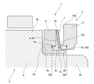
- FIG. 3 is a cross-sectional view of a main part showing a first embodiment of the friction generation mechanism according to the present invention.
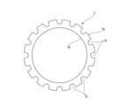
- FIG. 3 is a cross-sectional view of a main part showing a third embodiment of the friction generation mechanism. The plan view of the cone spring in the 3rd Example.
- FIG. 3 is a cross-sectional view of a main part showing a fourth embodiment of the friction generation mechanism.
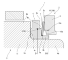
- FIG. 1 shows a first embodiment of the friction generating mechanism 1, which is a main part of the damper device according to the present invention.
- the overall configuration of the damper device is a known configuration as disclosed in Patent Document 1 and the like, and is not shown. However, for example, it is attached to a flywheel of an internal combustion engine and the torque of the internal combustion engine is input. It has an input-side rotating member 2 to be formed, and an output-side rotating member 3 that is rotatably combined with respect to the input-side rotating member 2.
- the output-side rotating member 3 includes, for example, a spline hub 4 spline-coupled to the input shaft of the transmission at the center of rotation.
- the spline hub 4 has a cylindrical boss portion 4a and a disk portion 4b extending from the axial center portion of the boss portion 4a to the outer peripheral side.
- the left side of FIG. 1 is the internal combustion engine side, and the right side is the transmission side.
- the input-side rotating member 2 is formed in a disk shape by joining the outer peripheral portions of a substantially circular retaining plate 5 located on the transmission side and a substantially circular cover plate (not shown) located on the internal combustion engine side to each other.
- the disk portion 4b of the spline hub 4, which is a part of the output side rotating member 3, is sandwiched between these two plates.
- a plurality of coil springs for example, four coil springs (not shown) (not shown) are arranged along the rotational tangential direction so as to elastically connect the two in the rotational direction. There is.
- the elastic force of this coil spring absorbs the torsional vibration.
- the thinning plate 5 and the cover plate (not shown) are formed by press-molding a metal plate. Note that FIG. 1 shows only the inner peripheral edge portion of the reinforcement plate 5.
- the friction generating mechanism 1 generates friction torque that is a damping force with respect to the relative rotation between the input side rotating member 2 and the output side rotating member 3, and is an annular shape made of a hard synthetic resin such as so-called engineering plastic. It is configured to include a bush 6 and an annular cone spring 7 arranged in a compressed state between the bush 6 and the reinforcement plate 5.
- the bush 6 is rotatably fitted to the outer peripheral surface of the boss portion 4a of the spline hub 4, and the annular friction surface 6a on the back surface side is in contact with the annular friction surface 4c of the disc portion 4b of the spline hub 4.
- These annular friction surfaces 6a and 4c are along a plane orthogonal to the rotation center axis (hereinafter, this is referred to as an axis orthogonal plane), and the friction torque is generated by the sliding contact between the two.
- the bush 6 has a cylindrical portion 6b extending toward the transmission side, whereby the bush 6 has a substantially L-shaped cross section as a whole.
- the cone spring 7 is fitted to the outer periphery of the cylindrical portion 6b, and is positioned in the radial direction by the cylindrical portion 6b.
- the inner peripheral side portion of the reinforcement plate 5 faces the bush 6 in the axial direction, and the cone spring 7 is arranged between the two.
- the inner peripheral end of the reinforcement plate 5 is located slightly on the outer peripheral side of the cylindrical portion 6b of the bush 6, and both of them partially overlap each other in the axial direction.
- the cone spring 7 has a tapered cross-sectional shape that is tilted at a relatively small angle with respect to the plane orthogonal to the axis.
- the inner peripheral edge 7a is located relatively closer to the bush 6 in the axial direction
- the outer peripheral edge 7b is located relatively closer to the linting plate 5 in the axial direction. It is tilted in the direction of.
- the inner peripheral edge 7a is continuous in a circular shape
- the outer peripheral edge 7b forms a plurality of notched portions 8 to form unevenness. It is formed in a shape.
- the bush 6 has a first load supporting surface 9 with which the inner peripheral edge 7a of the cone spring 7 abuts.
- the first load-bearing surface 9 rises at a right angle from the inner peripheral surface of the cylindrical portion 6b, and is formed along an axis orthogonal plane.
- the reinforcement plate 5 has a second load support surface 10 with which the outer peripheral edge 7b of the cone spring 7 abuts.
- the second load support surface 10 is also formed along an axis orthogonal plane.
- the first load-bearing surface 9 and the second load-bearing surface 10 face each other in the axial direction.
- a step portion 9a retracted in the axial direction is formed so as to receive the outer peripheral edge 7b of the cone spring 7 when the cone spring 7 is erroneously incorporated in the opposite direction. ing.
- the step portion 9a is located on the outer peripheral side of the bush 6. Normally, the cone spring 7 does not come into contact with the step portion 9a. Therefore, the substantially first load supporting surface 9 is only the flat surface portion 9b on the inner peripheral side excluding the step portion 9a.
- the second load-bearing surface 10 is formed with a step portion 10a retracted axially so as to receive the inner peripheral edge 7a of the cone spring 7 when the cone spring 7 is erroneously incorporated in the opposite direction.
- the step portion 10a is formed by drawing the inner peripheral edge of the reinforcement plate 5 made of a metal plate. Normally, the cone spring 7 does not come into contact with the step portion 10a. Therefore, the substantially second load supporting surface 10 is only the flat surface portion 10b on the outer peripheral side excluding the step portion 10a.
- the radial position of the boundary 9c of the step portion 9a on the first load support surface 9 is on the outer peripheral side of the radial position of the boundary 10c of the step portion 10a on the second load support surface 10. That is, as shown in FIG. 1, the diameter D1 of the boundary 9c on the first load-bearing surface 9 is larger than the diameter D2 of the boundary 10c on the second load-bearing surface 10. Therefore, when the first load support surface 9 and the second load support surface 10 are projected in the axial direction, the flat surface portion 9b on the inner peripheral side which is substantially the first load support surface 9 And the flat surface portion 10b on the outer peripheral side, which is substantially the second load support surface 10, overlap each other with a certain radial width.
- a cone spring 7 having an outer peripheral edge 7b supported by the linting plate 5 attaches the bush 6 in the axial direction toward the disk portion 4b.
- FIG. 3 shows a state in which the cone spring 7 is erroneously incorporated in the opposite direction.
- the outer peripheral edge 7b of the cone spring 7 having a taper in the direction opposite to the correct posture supports the first load. It enters the stepped portion 9a of the surface 9, and the inner peripheral edge 7a enters the stepped portion 10a of the second load supporting surface 10. Therefore, as can be easily understood by comparing with FIG. 1, the urging force in the axial direction of the cone spring 7 is greatly reduced. Therefore, if the friction torque of the friction generating mechanism 1 is inspected after assembling the damper device, it is easy to detect that the assembly is incorrect.
- the cone spring 7 when an excessive load is applied to the cone spring 7 in the axial direction, the cone spring 7 is inverted so as to be in the direction opposite to the original taper direction. It can be a factor in the phenomenon.
- the relationship of "D1> D2" as described above does not cause the cone spring 7 to reverse even if an excessive load is applied in the axial direction. That is, the cone spring 7 is sandwiched between the two load supporting surfaces 9, 10 (flat surface portions 9b, 10b) that exist between the diameter D1 and the diameter D2 and are parallel to each other and along the axis orthogonal plane. However, a moment that reverses the cone spring 7 is not generated. This action will be further described later with reference to the second embodiment.
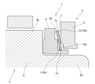
- FIG. 4 shows a second embodiment of the friction generation mechanism 1.
- the description overlapping with the description of the first embodiment will be omitted.
- the outer peripheral edge 7b of the cone spring 7 is attached.
- a receiving step 9a is formed.
- the step portion 10a as in the first embodiment is not formed on the second load support surface 10 on the reinforcement plate 5 side. That is, the second load-bearing surface 10 forms a flat surface up to the inner peripheral side edge 10d facing the vicinity of the inner peripheral edge 7a of the cone spring 7.
- the radial position of the boundary 9c of the step portion 9a on the first load support surface 9 is on the outer peripheral side of the radial position of the inner peripheral side edge 10d of the second load support surface 10. That is, the diameter D3 of the boundary 9c on the first load-bearing surface 9 is larger than the diameter D4 of the inner peripheral side edge 10d on the second load-bearing surface 10. Therefore, when the first load support surface 9 and the second load support surface 10 are projected in the axial direction, the flat surface portion 9b on the inner peripheral side which is substantially the first load support surface 9 And the flat second load-bearing surface 10 overlap each other with a certain radial width.
- the step portion 9a is provided only on the first load support surface 9 as described above, when the cone spring 7 is erroneously incorporated in the opposite direction, the outer peripheral edge 7b of the cone spring 7 enters the step portion 9a. As a result, the urging force in the axial direction of the cone spring 7 is greatly reduced, and therefore detection in the inspection process is possible.
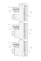
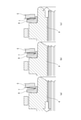
- FIG. 5 is an explanatory diagram illustrating a mechanism for preventing the cone spring 7 from reversing with respect to an axial load, and here, a second embodiment will be described as an example.
- FIG. (B) shows a neutral state under no axial load. Since the cone spring 7 is in the compressed normal state in the initial assembled state, in this example, it is displaced to a state close to flat.
- FIG. (A) shows a state in which the spline hub 4 which is the output side rotating member 3 receives an axial load to the left side of the figure as shown by an arrow with respect to the filling plate 5 which is the input side rotating member 2. With the axial load in this direction, the cone spring 7 does not particularly reverse.
- FIG. (C) shows a state in which the spline hub 4, which is the output side rotating member 3, receives an axial load to the right side of the figure as indicated by an arrow.
- the inner peripheral edge 7a of the cone spring 7 is pushed to the right side of the figure, and the outer peripheral edge 7b of the cone spring 7 is pushed to the left side of the figure.
- the cone spring 7 is sandwiched between the flat first load supporting surface 9 (flat surface portion 9b) and the second load supporting surface 10 that overlap each other. It becomes a shape and does not generate a moment to reverse the cone spring 7.
- FIG. 6 is an explanatory diagram illustrating the inversion of the cone spring 7 in the comparative example.
- This comparative example corresponds to, for example, in the first embodiment of FIG. 1, the magnitude relationship between the diameter D1 and the diameter D2 is reversed to "D1 ⁇ D2". That is, the boundary 9c of the step portion 9a on the first load support surface 9 is located relatively on the inner peripheral side of the boundary 10c of the step portion 10a on the second load support surface 10.
- FIG. (B) shows a neutral state in which an axial load is not received, and FIG. As shown by, the state where the axial load is applied is shown on the left side of the figure.
- FIG. (C) shows a state in which the spline hub 4, which is the output side rotating member 3, receives an axial load to the right side of the figure as indicated by an arrow.
- a large axial load acts in the direction shown in FIG. 3C
- the inner peripheral edge 7a of the cone spring 7 is pushed to the right side of the figure
- the outer peripheral edge 7b of the cone spring 7 is pushed to the left side of the figure.
- the point of action of the force pushing the cone spring 7 to the right side of the figure is located on the inner peripheral side of the point of action of the force pushing the cone spring 7 to the left side of the figure. Therefore, a moment acts that causes the cone spring 7 to taper in the opposite direction beyond the flat state, and the cone spring 7 may be inverted as shown in the figure. And, at the time of inversion, cracks often occur.
- the cone spring 7 has a tapered cross section inclined in the direction opposite to that of the cone springs 7 of the first and second embodiments. Further, as shown in FIG. 8, in the cone spring 7 used in the third embodiment, the outer peripheral edge 7b is continuously formed in a circular shape, and the inner peripheral edge 7a is formed in an uneven shape by forming a plurality of notched portions 8. There is.
- the bush 6 has a first load-bearing surface 9 with which the outer peripheral edge 7b of the cone spring 7 abuts.
- the linting plate 5 has a second load-bearing surface 10 with which the inner peripheral edge 7a of the cone spring 7 abuts.
- the first load-bearing surface 9 and the second load-bearing surface 10 are also formed along an axis orthogonal plane and face each other in the axial direction.
- a step portion 9a retracted in the axial direction so as to receive the inner peripheral edge 7a of the cone spring 7 when the cone spring 7 is erroneously incorporated in the opposite direction is an inner circumference. It is formed on the side. Normally, the cone spring 7 does not come into contact with the step portion 9a. Therefore, the substantially first load supporting surface 9 is only the flat surface portion 9b on the outer peripheral side excluding the step portion 9a.
- the portion 10a is formed. Normally, the cone spring 7 does not come into contact with the step portion 10a. Therefore, the substantially second load supporting surface 10 is only the flat surface portion 10b on the inner peripheral side excluding the step portion 10a.
- the radial position of the boundary 9c of the step portion 9a on the first load support surface 9 is on the inner peripheral side of the radial position of the boundary 10c of the step portion 10a on the second load support surface 10. That is, as shown in FIG. 7, the diameter D5 of the boundary 9c on the first load-bearing surface 9 is smaller than the diameter D6 of the boundary 10c on the second load-bearing surface 10. Therefore, when the first load support surface 9 and the second load support surface 10 are projected in the axial direction, the flat surface portion 9b on the outer peripheral side which is substantially the first load support surface 9 The flat surface portion 10b on the inner peripheral side, which is substantially the second load support surface 10, overlaps with each other with a certain radial width.
- the cone spring 7 is erroneously incorporated in the opposite direction, the inner peripheral edge 7a of the cone spring 7 enters the stepped portion 9a and the outer peripheral edge 7b enters the stepped portion 10a.
- the urging force of the spring 7 is significantly reduced. Therefore, it is possible to detect an abnormality in the inspection process.
- the uneven inner peripheral edge 7a of the cone spring 7 comes into contact with the metal tangent plate 5.
- FIG. 9 shows a fourth embodiment of the friction generation mechanism 1.
- the cone spring 7 is mistakenly incorporated in the inner peripheral side portion of the first load supporting surface 9 in the bush 6, the cone spring 7 is incorporated in the reverse direction.
- a step 9a is formed to receive the inner peripheral edge 7a of the corn.
- the step portion 10a as in the third embodiment is not formed on the second load support surface 10 on the reinforcement plate 5 side. That is, the entire second load-bearing surface 10 is a flat surface from the inner peripheral side edge 10d to the portion facing the outer peripheral edge 7b of the cone spring 7.
- the radial position of the boundary 9c of the step portion 9a on the first load support surface 9 is within the radial range of the second load support surface 10 forming the flat surface. That is, when the first load support surface 9 and the second load support surface 10 are projected in the axial direction, the flat surface portion 9b on the outer peripheral side which is substantially the first load support surface 9 is formed. It overlaps the flat second load bearing surface 10.
- the step portion 9a is provided only on the first load support surface 9 as described above, when the cone spring 7 is erroneously incorporated in the opposite direction, the inner peripheral edge 7a of the cone spring 7 enters the step portion 9a. As a result, the urging force in the axial direction of the cone spring 7 is greatly reduced, and therefore detection in the inspection process is possible.
Landscapes
- Engineering & Computer Science (AREA)
- General Engineering & Computer Science (AREA)
- Physics & Mathematics (AREA)
- Acoustics & Sound (AREA)
- Aviation & Aerospace Engineering (AREA)
- Mechanical Engineering (AREA)
- Springs (AREA)
- Mechanical Operated Clutches (AREA)
- Support Of The Bearing (AREA)
Abstract
Description
上記第1の荷重支持面および上記第2の荷重支持面には、上記コーンスプリングが逆向きに組み込まれたときに当該コーンスプリングの外周縁および内周縁を受容するように軸方向に後退した段部がそれぞれ形成されており、
上記第1の荷重支持面における上記段部の境界の径方向位置が、上記第2の荷重支持面における上記段部の境界の径方向位置よりも外周側にある。
上記第1の荷重支持面には、上記コーンスプリングが逆向きに組み込まれたときに当該コーンスプリングの外周縁を受容するように軸方向に後退した段部が形成されており、
上記第1の荷重支持面における上記段部の境界の径方向位置が、平坦面をなす上記第2の荷重支持面の内周側端縁の径方向位置よりも外周側にある。
上記第1の荷重支持面および上記第2の荷重支持面には、上記コーンスプリングが逆向きに組み込まれたときに当該コーンスプリングの内周縁および外周縁を受容するように軸方向に後退した段部がそれぞれ形成されており、
上記第1の荷重支持面における上記段部の境界の径方向位置が、上記第2の荷重支持面における上記段部の境界の径方向位置よりも内周側にある。
上記第1の荷重支持面には、上記コーンスプリングが逆向きに組み込まれたときに当該コーンスプリングの内周縁を受容するように軸方向に後退した段部が形成されており、
上記第1の荷重支持面における上記段部の境界の径方向位置が、平坦面をなす上記第2の荷重支持面の径方向範囲内にある。
Claims (7)
- 第1の回転部材と、
上記第1の回転部材に対して相対回転可能に配置された第2の回転部材と、
上記第1の回転部材と上記第2の回転部材とを回転方向に弾性的に連結するためのばね部材と、
上記第1の回転部材と上記第2の回転部材との相対回転に対して摩擦トルクを発生する摩擦発生機構と、
を備えたダンパ装置であって、
上記摩擦発生機構は、
背面が上記第2の回転部材の環状摩擦面に接する断面略L字形をなすブッシュと、
上記ブッシュに軸方向に対向する上記第1の回転部材の一部であるリティニングプレートと、
上記ブッシュと上記リティニングプレートとの間に圧縮状態で配置されて上記ブッシュを上記環状摩擦面へ向けて付勢する環状のコーンスプリングと、
を備え、
上記コーンスプリングの内周縁が当接する第1の荷重支持面が上記ブッシュに、外周縁が当接する第2の荷重支持面が上記リティニングプレートに、互いに対向して形成されており、
上記第1の荷重支持面および上記第2の荷重支持面には、上記コーンスプリングが逆向きに組み込まれたときに当該コーンスプリングの外周縁および内周縁を受容するように軸方向に後退した段部がそれぞれ形成されており、
上記第1の荷重支持面における上記段部の境界の径方向位置が、上記第2の荷重支持面における上記段部の境界の径方向位置よりも外周側にある、ダンパ装置。 - 第1の回転部材と、
上記第1の回転部材に対して相対回転可能に配置された第2の回転部材と、
上記第1の回転部材と上記第2の回転部材とを回転方向に弾性的に連結するためのばね部材と、
上記第1の回転部材と上記第2の回転部材との相対回転に対して摩擦トルクを発生する摩擦発生機構と、
を備えたダンパ装置であって、
上記摩擦発生機構は、
背面が上記第2の回転部材の環状摩擦面に接する断面略L字形をなすブッシュと、
上記ブッシュに軸方向に対向する上記第1の回転部材の一部であるリティニングプレートと、
上記ブッシュと上記リティニングプレートとの間に圧縮状態で配置されて上記ブッシュを上記環状摩擦面へ向けて付勢する環状のコーンスプリングと、
を備え、
上記コーンスプリングの内周縁が当接する第1の荷重支持面が上記ブッシュに、外周縁が当接する第2の荷重支持面が上記リティニングプレートに、互いに対向して形成されており、
上記第1の荷重支持面には、上記コーンスプリングが逆向きに組み込まれたときに当該コーンスプリングの外周縁を受容するように軸方向に後退した段部が形成されており、
上記第1の荷重支持面における上記段部の境界の径方向位置が、平坦面をなす上記第2の荷重支持面の内周側端縁の径方向位置よりも外周側にある、ダンパ装置。 - 第1の回転部材と、
上記第1の回転部材に対して相対回転可能に配置された第2の回転部材と、
上記第1の回転部材と上記第2の回転部材とを回転方向に弾性的に連結するためのばね部材と、
上記第1の回転部材と上記第2の回転部材との相対回転に対して摩擦トルクを発生する摩擦発生機構と、
を備えたダンパ装置であって、
上記摩擦発生機構は、
背面が上記第2の回転部材の環状摩擦面に接する断面略L字形をなすブッシュと、
上記ブッシュに軸方向に対向する上記第1の回転部材の一部であるリティニングプレートと、
上記ブッシュと上記リティニングプレートとの間に圧縮状態で配置されて上記ブッシュを上記環状摩擦面へ向けて付勢する環状のコーンスプリングと、
を備え、
上記コーンスプリングの外周縁が当接する第1の荷重支持面が上記ブッシュに、内周縁が当接する第2の荷重支持面が上記リティニングプレートに、互いに対向して形成されており、
上記第1の荷重支持面および上記第2の荷重支持面には、上記コーンスプリングが逆向きに組み込まれたときに当該コーンスプリングの内周縁および外周縁を受容するように軸方向に後退した段部がそれぞれ形成されており、
上記第1の荷重支持面における上記段部の境界の径方向位置が、上記第2の荷重支持面における上記段部の境界の径方向位置よりも内周側にある、ダンパ装置。 - 第1の回転部材と、
上記第1の回転部材に対して相対回転可能に配置された第2の回転部材と、
上記第1の回転部材と上記第2の回転部材とを回転方向に弾性的に連結するためのばね部材と、
上記第1の回転部材と上記第2の回転部材との相対回転に対して摩擦トルクを発生する摩擦発生機構と、
を備えたダンパ装置であって、
上記摩擦発生機構は、
背面が上記第2の回転部材の環状摩擦面に接する断面略L字形をなすブッシュと、
上記ブッシュに軸方向に対向する上記第1の回転部材の一部であるリティニングプレートと、
上記ブッシュと上記リティニングプレートとの間に圧縮状態で配置されて上記ブッシュを上記環状摩擦面へ向けて付勢する環状のコーンスプリングと、
を備え、
上記コーンスプリングの外周縁が当接する第1の荷重支持面が上記ブッシュに、内周縁が当接する第2の荷重支持面が上記リティニングプレートに、互いに対向して形成されており、
上記第1の荷重支持面には、上記コーンスプリングが逆向きに組み込まれたときに当該コーンスプリングの内周縁を受容するように軸方向に後退した段部が形成されており、
上記第1の荷重支持面における上記段部の境界の径方向位置が、平坦面をなす上記第2の荷重支持面の径方向範囲内にある、ダンパ装置。 - 上記コーンスプリングの内周縁は円形に連続しており、外周縁は、複数の切欠部により凹凸状に形成されている、請求項1または2に記載のダンパ装置。
- 上記コーンスプリングの外周縁は円形に連続しており、内周縁は、複数の切欠部により凹凸状に形成されている、請求項3または4に記載のダンパ装置。
- 上記ブッシュが合成樹脂からなり、上記リティニングプレートが金属からなる、請求項1~6のいずれかに記載のダンパ装置。
Priority Applications (4)
| Application Number | Priority Date | Filing Date | Title |
|---|---|---|---|
| JP2022546294A JP7375213B2 (ja) | 2020-09-04 | 2021-08-27 | ダンパ装置 |
| US18/043,763 US12553493B2 (en) | 2020-09-04 | 2021-08-27 | Damper apparatus |
| CN202180051609.XA CN115917182B (zh) | 2020-09-04 | 2021-08-27 | 减振装置 |
| EP21864254.4A EP4209692A4 (en) | 2020-09-04 | 2021-08-27 | Damper apparatus |
Applications Claiming Priority (2)
| Application Number | Priority Date | Filing Date | Title |
|---|---|---|---|
| JP2020148674 | 2020-09-04 | ||
| JP2020-148674 | 2020-09-04 |
Publications (1)
| Publication Number | Publication Date |
|---|---|
| WO2022050196A1 true WO2022050196A1 (ja) | 2022-03-10 |
Family
ID=80491771
Family Applications (1)
| Application Number | Title | Priority Date | Filing Date |
|---|---|---|---|
| PCT/JP2021/031578 Ceased WO2022050196A1 (ja) | 2020-09-04 | 2021-08-27 | ダンパ装置 |
Country Status (5)
| Country | Link |
|---|---|
| US (1) | US12553493B2 (ja) |
| EP (1) | EP4209692A4 (ja) |
| JP (1) | JP7375213B2 (ja) |
| CN (1) | CN115917182B (ja) |
| WO (1) | WO2022050196A1 (ja) |
Cited By (1)
| Publication number | Priority date | Publication date | Assignee | Title |
|---|---|---|---|---|
| JPWO2024224810A1 (ja) * | 2023-04-28 | 2024-10-31 |
Citations (2)
| Publication number | Priority date | Publication date | Assignee | Title |
|---|---|---|---|---|
| JP2003074636A (ja) | 2001-08-31 | 2003-03-12 | Exedy Corp | ダンパー機構 |
| JP2006170388A (ja) * | 2004-12-17 | 2006-06-29 | Exedy Corp | 摩擦発生機構 |
Family Cites Families (5)
| Publication number | Priority date | Publication date | Assignee | Title |
|---|---|---|---|---|
| DE3921283A1 (de) * | 1989-02-08 | 1990-08-09 | Fichtel & Sachs Ag | Kupplungsscheibe mit torsionsschwingungsdaempfer und radial elastischer lagerung |
| DE19747220C2 (de) * | 1997-10-25 | 2002-01-24 | Mannesmann Sachs Ag | Kupplungsscheibe für eine Kraftfahrzeug-Reibungskupplung |
| JP3825190B2 (ja) | 1998-12-15 | 2006-09-20 | 株式会社エクセディ | 摩擦ブッシュ |
| JP5742326B2 (ja) * | 2011-03-15 | 2015-07-01 | アイシン精機株式会社 | トルク変動吸収装置 |
| JP6956047B2 (ja) * | 2018-06-13 | 2021-10-27 | 本田技研工業株式会社 | ダンパー装置 |
-
2021
- 2021-08-27 JP JP2022546294A patent/JP7375213B2/ja active Active
- 2021-08-27 WO PCT/JP2021/031578 patent/WO2022050196A1/ja not_active Ceased
- 2021-08-27 CN CN202180051609.XA patent/CN115917182B/zh active Active
- 2021-08-27 EP EP21864254.4A patent/EP4209692A4/en active Pending
- 2021-08-27 US US18/043,763 patent/US12553493B2/en active Active
Patent Citations (2)
| Publication number | Priority date | Publication date | Assignee | Title |
|---|---|---|---|---|
| JP2003074636A (ja) | 2001-08-31 | 2003-03-12 | Exedy Corp | ダンパー機構 |
| JP2006170388A (ja) * | 2004-12-17 | 2006-06-29 | Exedy Corp | 摩擦発生機構 |
Non-Patent Citations (1)
| Title |
|---|
| See also references of EP4209692A4 |
Cited By (3)
| Publication number | Priority date | Publication date | Assignee | Title |
|---|---|---|---|---|
| JPWO2024224810A1 (ja) * | 2023-04-28 | 2024-10-31 | ||
| WO2024224810A1 (ja) * | 2023-04-28 | 2024-10-31 | 日産自動車株式会社 | ダンパ装置 |
| JP7901247B2 (ja) | 2023-04-28 | 2026-08-05 | 日産自動車株式会社 | ダンパ装置 |
Also Published As
| Publication number | Publication date |
|---|---|
| EP4209692A1 (en) | 2023-07-12 |
| JPWO2022050196A1 (ja) | 2022-03-10 |
| EP4209692A4 (en) | 2024-06-05 |
| CN115917182A (zh) | 2023-04-04 |
| JP7375213B2 (ja) | 2023-11-07 |
| US20230313860A1 (en) | 2023-10-05 |
| US12553493B2 (en) | 2026-02-17 |
| CN115917182B (zh) | 2026-05-08 |
Similar Documents
| Publication | Publication Date | Title |
|---|---|---|
| JP5625676B2 (ja) | トルク変動吸収装置 | |
| WO2017043316A1 (ja) | トルク変動抑制装置、トルクコンバータ、及び動力伝達装置 | |
| JP6756129B2 (ja) | ダンパ装置 | |
| JP6657041B2 (ja) | トルク変動抑制装置、トルクコンバータ、及び動力伝達装置 | |
| JP2018504565A (ja) | 自動車の動力伝達チェーンに対する振動減衰装置 | |
| JP2022544219A (ja) | 遠心振り子、遠心振り子を含むトルク伝達装置、および車両 | |
| JP7375213B2 (ja) | ダンパ装置 | |
| CN110145553A (zh) | 离合器从动盘及离合器 | |
| JP2006144861A (ja) | クラッチディスク | |
| JP2014228124A (ja) | クラッチディスク | |
| JP2008039113A (ja) | スプリングシート及びスプリング組立体 | |
| JP2021134835A (ja) | スプリングシート及びダンパ装置 | |
| JPH09100874A (ja) | ダンパーディスク組立体 | |
| JP2002181131A (ja) | トルク伝達装置 | |
| JP2018013144A (ja) | 動吸振器 | |
| US20040206201A1 (en) | Flywheel assembly | |
| JP6708004B2 (ja) | ダンパ装置 | |
| JP5030846B2 (ja) | 捩り振動低減装置 | |
| JP2012237429A (ja) | 捩り振動減衰装置 | |
| JP7002402B2 (ja) | ダンパー装置 | |
| JP2023021751A (ja) | ダンパ装置 | |
| CN113309817A (zh) | 减振装置 | |
| JP3365590B2 (ja) | ダンパーディスク組立体 | |
| KR102467897B1 (ko) | 클러치 조립체 | |
| JP2002310185A (ja) | クラッチディスク組立体 |
Legal Events
| Date | Code | Title | Description |
|---|---|---|---|
| 121 | Ep: the epo has been informed by wipo that ep was designated in this application |
Ref document number: 21864254 Country of ref document: EP Kind code of ref document: A1 |
|
| ENP | Entry into the national phase |
Ref document number: 2022546294 Country of ref document: JP Kind code of ref document: A |
|
| NENP | Non-entry into the national phase |
Ref country code: DE |
|
| ENP | Entry into the national phase |
Ref document number: 2021864254 Country of ref document: EP Effective date: 20230404 |
|
| WWG | Wipo information: grant in national office |
Ref document number: 18043763 Country of ref document: US |