WO2022050247A1 - 流体デバイス及びその使用 - Google Patents
流体デバイス及びその使用 Download PDFInfo
- Publication number
- WO2022050247A1 WO2022050247A1 PCT/JP2021/031830 JP2021031830W WO2022050247A1 WO 2022050247 A1 WO2022050247 A1 WO 2022050247A1 JP 2021031830 W JP2021031830 W JP 2021031830W WO 2022050247 A1 WO2022050247 A1 WO 2022050247A1
- Authority
- WO
- WIPO (PCT)
- Prior art keywords
- well
- fluid device
- array
- less
- aqueous medium
- Prior art date
- Legal status (The legal status is an assumption and is not a legal conclusion. Google has not performed a legal analysis and makes no representation as to the accuracy of the status listed.)
- Ceased
Links
Images



Classifications
-
- G—PHYSICS
- G01—MEASURING; TESTING
- G01N—INVESTIGATING OR ANALYSING MATERIALS BY DETERMINING THEIR CHEMICAL OR PHYSICAL PROPERTIES
- G01N21/00—Investigating or analysing materials by the use of optical means, i.e. using sub-millimetre waves, infrared, visible or ultraviolet light
- G01N21/01—Arrangements or apparatus for facilitating the optical investigation
- G01N21/03—Cuvette constructions
-
- B—PERFORMING OPERATIONS; TRANSPORTING
- B01—PHYSICAL OR CHEMICAL PROCESSES OR APPARATUS IN GENERAL
- B01L—CHEMICAL OR PHYSICAL LABORATORY APPARATUS FOR GENERAL USE
- B01L3/00—Containers or dishes for laboratory use, e.g. laboratory glassware; Droppers
- B01L3/50—Containers for the purpose of retaining a material to be analysed, e.g. test tubes
- B01L3/502—Containers for the purpose of retaining a material to be analysed, e.g. test tubes with fluid transport, e.g. in multi-compartment structures
- B01L3/5027—Containers for the purpose of retaining a material to be analysed, e.g. test tubes with fluid transport, e.g. in multi-compartment structures by integrated microfluidic structures, i.e. dimensions of channels and chambers are such that surface tension forces are important, e.g. lab-on-a-chip
- B01L3/502715—Containers for the purpose of retaining a material to be analysed, e.g. test tubes with fluid transport, e.g. in multi-compartment structures by integrated microfluidic structures, i.e. dimensions of channels and chambers are such that surface tension forces are important, e.g. lab-on-a-chip characterised by interfacing components, e.g. fluidic, electrical, optical or mechanical interfaces
-
- B—PERFORMING OPERATIONS; TRANSPORTING
- B01—PHYSICAL OR CHEMICAL PROCESSES OR APPARATUS IN GENERAL
- B01L—CHEMICAL OR PHYSICAL LABORATORY APPARATUS FOR GENERAL USE
- B01L3/00—Containers or dishes for laboratory use, e.g. laboratory glassware; Droppers
- B01L3/50—Containers for the purpose of retaining a material to be analysed, e.g. test tubes
- B01L3/502—Containers for the purpose of retaining a material to be analysed, e.g. test tubes with fluid transport, e.g. in multi-compartment structures
- B01L3/5025—Containers for the purpose of retaining a material to be analysed, e.g. test tubes with fluid transport, e.g. in multi-compartment structures for parallel transport of multiple samples
-
- B—PERFORMING OPERATIONS; TRANSPORTING
- B01—PHYSICAL OR CHEMICAL PROCESSES OR APPARATUS IN GENERAL
- B01L—CHEMICAL OR PHYSICAL LABORATORY APPARATUS FOR GENERAL USE
- B01L3/00—Containers or dishes for laboratory use, e.g. laboratory glassware; Droppers
- B01L3/50—Containers for the purpose of retaining a material to be analysed, e.g. test tubes
- B01L3/502—Containers for the purpose of retaining a material to be analysed, e.g. test tubes with fluid transport, e.g. in multi-compartment structures
- B01L3/5027—Containers for the purpose of retaining a material to be analysed, e.g. test tubes with fluid transport, e.g. in multi-compartment structures by integrated microfluidic structures, i.e. dimensions of channels and chambers are such that surface tension forces are important, e.g. lab-on-a-chip
-
- B—PERFORMING OPERATIONS; TRANSPORTING
- B01—PHYSICAL OR CHEMICAL PROCESSES OR APPARATUS IN GENERAL
- B01L—CHEMICAL OR PHYSICAL LABORATORY APPARATUS FOR GENERAL USE
- B01L7/00—Heating or cooling apparatus; Heat insulating devices
-
- G—PHYSICS
- G01—MEASURING; TESTING
- G01N—INVESTIGATING OR ANALYSING MATERIALS BY DETERMINING THEIR CHEMICAL OR PHYSICAL PROPERTIES
- G01N21/00—Investigating or analysing materials by the use of optical means, i.e. using sub-millimetre waves, infrared, visible or ultraviolet light
- G01N21/01—Arrangements or apparatus for facilitating the optical investigation
- G01N21/11—Filling or emptying of cuvettes
-
- B—PERFORMING OPERATIONS; TRANSPORTING
- B01—PHYSICAL OR CHEMICAL PROCESSES OR APPARATUS IN GENERAL
- B01L—CHEMICAL OR PHYSICAL LABORATORY APPARATUS FOR GENERAL USE
- B01L2200/00—Solutions for specific problems relating to chemical or physical laboratory apparatus
- B01L2200/06—Fluid handling related problems
- B01L2200/0673—Handling of plugs of fluid surrounded by immiscible fluid
-
- B—PERFORMING OPERATIONS; TRANSPORTING
- B01—PHYSICAL OR CHEMICAL PROCESSES OR APPARATUS IN GENERAL
- B01L—CHEMICAL OR PHYSICAL LABORATORY APPARATUS FOR GENERAL USE
- B01L2200/00—Solutions for specific problems relating to chemical or physical laboratory apparatus
- B01L2200/06—Fluid handling related problems
- B01L2200/0689—Sealing
-
- B—PERFORMING OPERATIONS; TRANSPORTING
- B01—PHYSICAL OR CHEMICAL PROCESSES OR APPARATUS IN GENERAL
- B01L—CHEMICAL OR PHYSICAL LABORATORY APPARATUS FOR GENERAL USE
- B01L2300/00—Additional constructional details
- B01L2300/04—Closures and closing means
- B01L2300/041—Connecting closures to device or container
-
- B—PERFORMING OPERATIONS; TRANSPORTING
- B01—PHYSICAL OR CHEMICAL PROCESSES OR APPARATUS IN GENERAL
- B01L—CHEMICAL OR PHYSICAL LABORATORY APPARATUS FOR GENERAL USE
- B01L2300/00—Additional constructional details
- B01L2300/08—Geometry, shape and general structure
- B01L2300/0809—Geometry, shape and general structure rectangular shaped
- B01L2300/0819—Microarrays; Biochips
-
- B—PERFORMING OPERATIONS; TRANSPORTING
- B01—PHYSICAL OR CHEMICAL PROCESSES OR APPARATUS IN GENERAL
- B01L—CHEMICAL OR PHYSICAL LABORATORY APPARATUS FOR GENERAL USE
- B01L2300/00—Additional constructional details
- B01L2300/08—Geometry, shape and general structure
- B01L2300/0809—Geometry, shape and general structure rectangular shaped
- B01L2300/0829—Multi-well plates; Microtitration plates
-
- B—PERFORMING OPERATIONS; TRANSPORTING
- B01—PHYSICAL OR CHEMICAL PROCESSES OR APPARATUS IN GENERAL
- B01L—CHEMICAL OR PHYSICAL LABORATORY APPARATUS FOR GENERAL USE
- B01L2300/00—Additional constructional details
- B01L2300/08—Geometry, shape and general structure
- B01L2300/0848—Specific forms of parts of containers
- B01L2300/0851—Bottom walls
-
- B—PERFORMING OPERATIONS; TRANSPORTING
- B01—PHYSICAL OR CHEMICAL PROCESSES OR APPARATUS IN GENERAL
- B01L—CHEMICAL OR PHYSICAL LABORATORY APPARATUS FOR GENERAL USE
- B01L2300/00—Additional constructional details
- B01L2300/08—Geometry, shape and general structure
- B01L2300/0861—Configuration of multiple channels and/or chambers in a single devices
- B01L2300/0877—Flow chambers
-
- B—PERFORMING OPERATIONS; TRANSPORTING
- B01—PHYSICAL OR CHEMICAL PROCESSES OR APPARATUS IN GENERAL
- B01L—CHEMICAL OR PHYSICAL LABORATORY APPARATUS FOR GENERAL USE
- B01L2300/00—Additional constructional details
- B01L2300/08—Geometry, shape and general structure
- B01L2300/0896—Nanoscaled
-
- G—PHYSICS
- G01—MEASURING; TESTING
- G01N—INVESTIGATING OR ANALYSING MATERIALS BY DETERMINING THEIR CHEMICAL OR PHYSICAL PROPERTIES
- G01N21/00—Investigating or analysing materials by the use of optical means, i.e. using sub-millimetre waves, infrared, visible or ultraviolet light
- G01N21/01—Arrangements or apparatus for facilitating the optical investigation
- G01N21/03—Cuvette constructions
- G01N2021/0346—Capillary cells; Microcells
Definitions
- the present invention relates to fluid devices and their use. More specifically, the present invention relates to a fluid device, a method for isolating an aqueous medium, and a method for detecting a detection target.
- the present application claims priority with respect to Japanese Patent Application No. 2020-147507 filed in Japan on September 2, 2020, the contents of which are incorporated herein by reference.
- biomolecules may be detected by introducing biomolecules into micropores and performing a reaction accompanied by heating.
- a technique capable of detecting a single molecule of a biomolecule is known. Examples of such a technique include digital ELISA (Digital Enzyme-Linked ImmunoSorbent Assay), digital PCR (Digital Primerase Reaction), and digital Invasive Creative Assay (Digital measurement).
- the inventors do not replace the air existing inside the wells with the reagents when introducing the reagents into each well. It has been found that it may remain and may interfere with the detection of biomolecules.
- an object of the present invention is to provide a technique for suppressing the residual air bubbles inside the wells when an aqueous medium is introduced into each well of a fluid device having a well array.
- a substrate having at least a part of a well array in which a plurality of wells having the same shape that open on one surface are regularly arranged, and a lid member arranged so as to face the well array are provided.
- the space between the well array and the lid member forms a flow path through which a fluid flows, and the center of gravity Ca of the opening of any well A of the well array and the opening of the well B closest to the well A.
- a method for detecting the detection target which comprises a step of generating a signal and a step of detecting the signal.
- the detection target is a biomolecule.
- the reaction is a constant temperature reaction.
- the method according to any one of [11] to [13], wherein the signal is fluorescent.
- (A) is a schematic cross-sectional view illustrating the structure of the fluid device
- (b) is a top view of the fluid device
- (c) is a partially enlarged view of the well array of the fluid device as seen from the opening surface side of the well. It is a figure (plan view).
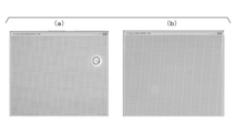
- (A) and (b) are photographs of a well array observed in a bright field by feeding a buffer to the fluid device of Example 1 in Experimental Example 1.
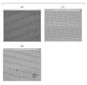
- (A) to (c) are photographs of a well array observed in a bright field by sending a buffer to the fluid device of Comparative Example 1 in Experimental Example 1.
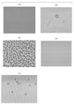
- (A) to (e) are photographs of a well array observed in a bright field by sending a buffer to the fluid device of Comparative Example 2 in Experimental Example 1.
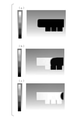
- (A) to (e) are cross-sectional views of a fluid device showing the results of the simulation in Experimental Example 2.
- (A) to (c) are cross-sectional views of a fluid device showing the results of the simulation in Experimental Example 3.
- (A) to (c) are cross-sectional views of a fluid device showing the results of the simulation in Experimental Example 4.
- (A) to (c) are cross-sectional views of a fluid device showing the results of the simulation in Experimental Example 5.
- the present invention comprises a substrate having at least a portion of a well array in which a plurality of wells of the same shape that open on one side are regularly arranged, and a lid member arranged so as to face the well array.
- the space between the well array and the lid member forms a flow path through which a fluid flows, and the center of gravity Ca of the opening of any well A of the well array and the well A are the most.
- a fluid device in which the distance Dab between the center of gravity Cb of the opening of the adjacent well B and the diameter Da of the circle having the same area as the area of the opening of the well A satisfy the following formula (1). .. 0.8 ⁇ Da / Dab ⁇ 1 ... (1)
- the fluid device of the present embodiment when an aqueous medium is introduced into each well of the well array, the residual air bubbles inside the wells can be suppressed.
- FIG. 1A is a schematic cross-sectional view illustrating the structure of the fluid device of the present embodiment
- FIG. 1B is a top view of the fluid device of the present embodiment
- FIG. 1C is a top view.
- the fluid device 100 of the present embodiment has a substrate 130 having at least a part of a well array 120 in which a plurality of wells 110 having the same shape open on one surface are regularly arranged. And a lid member 140 arranged to face the well array 120, and the space 150 between the well array 120 and the lid member 140 forms a flow path through which a fluid flows.
- the flow path 150 is a continuous space between the surface 131 of the substrate 130 and the surface 141 of the lid member 140.
- the center of gravity of the opening of any well A of the well array 120 (that is, the center of gravity of the shape defined by the peripheral edge of the opening) Ca and the well A are the most.
- the distance Dab between the center of gravity Cb of the opening of the adjacent well B and the diameter Da when assuming a circle having the same area as the area of the opening of the well A satisfy the following equation (1). 0.8 ⁇ Da / Dab ⁇ 1 ... (1)
- the lower limit of the value of Da / Dab is 0.8, which may be 0.83 or more. Further, the upper limit of the value of Da / Dab is less than 1, may be 0.92 or less, or may be about 0.9. These lower and upper limits can be combined arbitrarily.
- the fluid device of the present embodiment may include an introduction port 160 for introducing the fluid into the flow path 150 and an discharge port 170 for discharging the fluid from the flow path 150.
- the introduction port 160 and the discharge port 170 are formed on the lid member 140, but the introduction port 160 and the discharge port 170 may be formed on the peripheral member 180 described later. Alternatively, it may be formed on the substrate 130.
- the introduction port 160 and the discharge port 170 are arranged at positions sandwiching the well array 120.
- the shapes of the introduction port 160 and the discharge port 170 are not particularly limited, and may be any conceivable shape as long as the fluid can be sent.
- it may be a circle, an ellipse, or a polygon such as a triangle, a quadrangle, a pentagon, a hexagon, a heptagon, and an octagon.
- the fluid device of the present embodiment preferably includes a peripheral member 180.
- the peripheral edge member 180 functions as a spacer for forming the flow path 150 by separating the substrate 130 and the lid member 140.
- the peripheral member 180 is also arranged around the well array 120 between the substrate 130 and the lid member 140, and forms a part of the wall surface of the flow path 150. That is, it is preferable that the flow path 150 is surrounded by the peripheral member 180 located between the surface 131 of the substrate 130 and the surface 141 of the lid member 140.
- the peripheral member 180 may be provided as an integral member that is continuously connected to the lid member 140.
- the cross-sectional shape on the plane perpendicular to the flow direction of the flow path 150 is not particularly limited, and any shape that can be assumed may be used as long as the shape can feed the fluid. For example, shapes such as squares, rectangles, triangles, circles, and ellipses can be mentioned. Further, the cross-sectional shape of the flow path 150 may be constant or may change from the introduction port 160 of the flow path 150 to the discharge port 170, but it is preferable that the cross-sectional shape is constant.
- the fluid device of the present embodiment may be a minute flow path, that is, a micro flow path, which is usually used when handling a biomolecule. More specifically, in the fluid device of the present embodiment, the maximum value of the cross-sectional area of the flow path may be 0.01 to 1 mm 2 .
- the well array 120 may be formed by forming a plurality of wells 110 on one surface 131 of the substrate 130, or the substrate 130 is a first layer having a plurality of through holes and a second plate which is a flat plate.
- the through holes may form the well 110, and the plurality of through holes may form the well array 120.
- the material of the substrate 130 is not particularly limited, and examples thereof include metals such as stainless steel, titanium, cobalt-chromium alloys, and magnesium alloys; glass; resin materials such as general-purpose plastics, medical plastics, and cosmetic plastics. Further, a plurality of materials made of these materials may be laminated.
- the resin material include polyethylene, polypropylene, polystyrene, polyamide, polycarbonate, cyclic polyolefin, polylactic acid, polyglycolic acid, polycaprolactone, acrylic, urethane resin, silicone resin, fluororesin, aromatic polyetherketone, and epoxy resin.
- a copolymerization material of these resins and the like can be mentioned.
- the material of the lid member 140 is not particularly limited, and examples thereof include the same materials as those of the substrate 130 described above.
- the shape of the opening of the well 110 (that is, the shape of the well 110 in the plan view of the fluid device 100 seen from the opening surface side of the well 110) is not particularly limited, and may be a circle or an ellipse. It may be a polygon such as a triangle, a quadrangle, a pentagon, a hexagon, a heptagon, and an octagon.
- the shape of the opening of the well 110 is a circle
- the center of gravity of the opening of the well 110 is the center of the circle.
- Each of the plurality of wells 110 constituting the well array 120 has the same shape and is regularly arranged. However, since it is used as an alignment mark in imaging and device manufacturing, a small number (for example, 1 to 4) of the plurality of wells may have different shapes. In this case, substantially all wells (ie, wells except the few wells mentioned above) have the same shape and are regularly arranged.
- the fact that the wells are regularly arranged means that the centers of gravity of the openings of the wells constituting the well array are arranged in a certain pattern.
- the centers of gravity of the openings of the wells may be arranged in a square grid pattern.
- the line connecting the centers of gravity of the openings of the four wells adjacent to each other forms a rectangle, preferably a square.
- the centers of gravity of the openings of the wells may be arranged in a triangular grid pattern (also referred to as a hexagonal grid pattern).
- the lines connecting the centers of gravity of the openings of the three wells adjacent to each other form an equilateral triangle.
- the distance between the center of gravity of the opening of any well and the center of gravity of the opening of the well closest to the well is constant for all wells.
- the wells shown in FIG. 1 (c) are arranged in a triangular lattice pattern. As shown in FIG. 1 (c), among the wells 110 constituting the well array 120, any well A, the well B closest to the well A, and the closest to both the well A and the well B.
- the centers of gravity Ca, Cb, and Cc of the respective openings of the wells C form an equilateral triangle with each as the apex.
- the line connecting the centers of gravity Ca, Cb, and Cc of the openings of wells A, B, and C is an equilateral triangle.
- the diameter is preferably 1 ⁇ m or more and 50 ⁇ m or less when a circle having the same area as the area of the well opening is assumed. That is, it is preferable that the lower limit of the diameter is 1 ⁇ m when a circle having the same area as the area of the opening of the well is assumed.
- the upper limit of the diameter when assuming a circle having the same area as the area of the opening of the well may be less than 20 ⁇ m, 19 ⁇ m or less, 18 ⁇ m or less, or 17 ⁇ m or less. It may be 16 ⁇ m or less, 15 ⁇ m or less, 14 ⁇ m or less, 13 ⁇ m or less, 12 ⁇ m or less, 11 ⁇ m or less. It may be 10 ⁇ m or less.
- the area of the well array 120 means the area of the area inscribed in the well 110 existing at the peripheral edge of the well array 120 on the surface 131.
- the ratio of the total area of the openings of each well 110 of the well array 120 to the area of the well array 120 on the surface 131 (hereinafter, may be referred to as “opening area ratio”) is 30% or more and 90% or less. It is preferable to have.
- the lower limit of the opening area ratio may be 60%, 45%, or 30%.
- the upper limit of the opening area ratio may be 90%, 80%, or 70%. These lower and upper limits can be combined arbitrarily.
- the opening area ratio may be 30% or more and 90% or less, 45% or more and 80% or less, and 60% or more and 70% or less.
- the volume per well 110 is preferably 10 fL or more and 100 pL or less, and more preferably 100 fL or more and 30 pL or less.
- the total volume of each well 110 constituting the well array 120 is preferably 0.2 ⁇ L or more and 2.0 ⁇ L or less, and more preferably 0.4 ⁇ L or more and 1.5 ⁇ L or less.
- the ratio of the diameter to the depth of the well 110 when assuming a circle having the same area as the area of the opening of the well 110 is preferably 3% or more and 200% or less, and 30% or more and 120% or less. More preferably, it is more preferably 60% or more and 90% or less.
- the ratio of the total volume of each well 110 constituting the well array 120 to the volume of the flow path 150 is preferably 5% or more and 40% or less.
- the contact angle of one surface 131 with water is preferably 70 degrees or more and 180 degrees or less. Further, the contact angle of the surface 141 of the lid member 140 facing the well array 120 with water is preferably 70 degrees or more and 180 degrees or less.
- the contact angles of the surfaces 131 and 141 are in the above range, the aqueous medium tends to be easily separated into each well of the well array when the sealing liquid is introduced into the flow path 150.
- the fluid device of this embodiment can be manufactured, for example, by the following procedure. First, a substrate is prepared, and a resin layer is formed on one surface of the substrate. By forming through holes in this resin layer, wells are formed on the substrate. A second resin layer may be provided between the substrate and the resin layer. Alternatively, an anchor layer or the like that enhances the adhesion between the substrate and the resin layer may be provided.
- the resin layer may be formed of a material in which a colored component is mixed with the resin material.
- the content of the colored component can be, for example, 0.5% by mass (also referred to as mass%) or more and 60 mass% or less. Regarding the content, it is preferably 5 mass% or more and 55 mass% or less, and more preferably 20 mass% or more and 50 mass% or less.
- the content of the colored component can be appropriately set so that a desired pattern can be constructed in consideration of the ratio of the photosensitive component and the like contained in the resist.
- the colored component may be a pigment, and a dispersant may be appropriately added together with the pigment.
- the formed resin layer is formed of a material obtained by mixing a colored component with a resin material, the resin layer has a color based on the colored component.
- a through hole is formed in the resin layer.
- through holes can be formed easily and accurately.
- the resin layer is formed by injection molding or the like, the formation of the resin layer and the formation of the through holes can be performed by the same process.
- through holes can be formed by etching using a pattern mask or the like.
- the well array 120 may be formed by forming a plurality of wells 110 on one surface 131 of the substrate 130.
- the substrate 130 having the well array 120 can be manufactured by injection molding the above-mentioned resin material using a mold corresponding to the shape of the well array 120.
- the peripheral member 180 is arranged around the well array 120.
- the lid member 140 is arranged on the peripheral member 180.
- the substrate 130, the peripheral member 180, and the lid member 140 are integrally joined to obtain the fluid device 100.
- the flow path 150 is formed between the lid member 140 and the substrate 130 by the peripheral member 180.
- the method of joining the substrate 130, the peripheral member 180, and the lid member 140 is not particularly limited, and known methods can be used, and examples thereof include laser welding, bonding with double-sided tape, and bonding with an adhesive.
- surface treatment may be performed on the surfaces of the substrate 130 and the lid member 140 to increase the adhesive effect before bonding.
- examples of the surface treatment include (1) chemical surface modification and (2) surface shape processing.
- peripheral member 180 and the lid member 140 may be integrally molded.
- the fluid device 100 can be manufactured by joining the substrate 130 having the well array 120 at least in a part thereof and the lid member 140 integrally formed with the peripheral member 180.
- the flow path 150 is formed between the lid member 140 and the substrate 130 by the peripheral member 180 integrally molded with the lid member 140.
- the fluid device can be manufactured by the above method.
- the method for manufacturing the fluid device is not limited to that described above, and other known methods that can be inferred in each step can be applied.
- the present invention comprises the steps of introducing an aqueous medium into the flow path of the fluid device described above, and after introducing the aqueous medium, introducing a encapsulant into the flow path to bring the aqueous medium into each well of the well array.
- introducing an aqueous medium including a step of isolating.
- the residual air bubbles inside the well can be suppressed.
- the aqueous medium and the encapsulant are immiscible or difficult to miscible with each other.
- Specific examples of the sealing liquid include fluorine-based liquids such as FC-40, FC-43, FC-770, FC-72, and FC-3283 (all manufactured by 3M).
- the aqueous medium may contain a detection target and a detection reagent.
- the detection target include biomolecules such as nucleic acids, proteins, and lipids.
- the detection reagent is appropriately selected according to the detection method.
- the aqueous medium may contain a surfactant.
- the method of the present embodiment includes a step of introducing a filler before introducing the aqueous medium, and the filler and the aqueous medium may be miscible with each other or easily miscible. This makes it easier to suppress the residual air bubbles inside the well.
- the filler include an aqueous medium containing a surfactant, an aqueous medium not containing a surfactant, and an organic solvent easily mixed with the aqueous medium.
- the filler contains a surfactant, the effect of suppressing the residual air bubbles inside the well, the effect of suppressing non-specific adsorption to the region between the wells on the surface 131 of the substrate 130, etc. Is obtained.
- the surfactant may be contained in both the aqueous medium and the filler, or may be contained in only one of them.
- the aqueous medium and the encapsulant may be introduced while applying pressure from the inlet of the fluid device.
- Introducing the aqueous medium and the encapsulant while applying pressure may be to inject the aqueous medium and the encapsulant using a syringe, a pipette or the like.
- the effect of suppressing the residual air bubbles inside the well can be easily obtained even when the introduction is performed while applying pressure.
- the present invention uses the above-mentioned method for isolating an aqueous medium to isolate an aqueous medium containing a detection target and a detection reagent in wells of a well array of a fluid device, and then heats the fluid device to provide a well.
- a method for detecting a detection target which comprises a step of generating a reaction internally and generating a signal for detecting the detection target, and a step of detecting the signal.
- the method of the present embodiment since the residual air bubbles inside the well are suppressed, it is easy to detect the detection target with high accuracy.
- the aqueous medium contains a detection target and a detection reagent.
- the detection target include biomolecules such as nucleic acids, proteins, and lipids.
- the detection reagent is appropriately selected according to the detection principle.
- the reaction that causes the signal may be a constant temperature reaction.
- the signal may be fluorescent.
- Examples of such a reaction include Invasive Cleared Assay (ICA).
- ICA Invasive Cleared Assay
- the detection target is nucleic acid
- examples of the detection reagent include flap probes, flap endonucleases (FEN), fluorescent substrates, and the like.
- a flap probe is a nucleic acid fragment designed to hybridize with a nucleic acid to be detected to form a double-stranded nucleic acid having a flap structure.
- the reaction that produces a signal preferably has a reaction temperature of 55 ° C. or higher and 75 ° C. or lower.
- the signal in the step of detecting the signal, may be detected by taking an image of the fluid device and analyzing the taken image.
- the invention includes the following aspects: [1] A substrate having at least a part of a well array in which a plurality of wells having the same shape that open on one surface are regularly arranged, and a lid member arranged so as to face the well array are provided.
- the space between the well array and the lid member forms a flow path through which a fluid flows, and the center of gravity Ca of the opening of any well A of the well array and the opening of the well B closest to the well A.
- [6] The fluid device according to any one of [1] to [5], wherein the ratio of the total volume of each well of the well array to the volume of the flow path is 5% or more and 100% or less.
- [7] The fluid according to any one of [1] to [6], wherein the ratio of the diameter of the circle having the same area as the area of the opening of the well to the depth of the well is 60% or more and 90% or less. device.
- [8] The fluid device according to any one of [1] to [7], wherein the contact angle with water on one surface is 70 degrees or more and 120 degrees or less.
- a method for detecting the detection target which comprises a step of generating a signal and a step of detecting the signal.
- the detection target is a biomolecule.
- the reaction is a constant temperature reaction.
- the method according to any one of [11] to [13], wherein the signal is fluorescent.
- the thickness of the substrate was 0.6 mm.
- a well array was formed on one surface of the substrate.
- the opening shape of the well was a circle.
- the well size was 10 ⁇ m in diameter and 15 ⁇ m in depth.
- the volume per well was 824 fL, the total volume of each well was 0.76 ⁇ L, and the ratio of the diameter of the well opening to the well depth was 66.7%.
- a plurality of wells are arranged in a triangular grid pattern so that the distance between the center of the well and the center of the well closest to the well is 12 ⁇ m. , Well arrays were formed.
- the contact angle of one surface of the substrate with water was 89 degrees.
- the lid member was integrally formed with the stepped portion (peripheral member). By adjusting the height of the stepped portion to 30 ⁇ m, the height of the flow path was set to 30 ⁇ m. The height of the actual flow path was measured using a contact type measuring instrument (part number "TALYSURF PGI1240", manufactured by Taylor Hobson). The volume of the flow path was about 6 ⁇ L, and the ratio of the total volume of each well to the volume of the flow path was about 12.7%. The contact angle of the surface of the lid member facing the well array with water was 89 degrees.
- the substrate and the stepped portion of the lid member were joined by laser welding to prepare the microfluidic device of Example 1.
- microfluidic device of Comparative Example 2 was produced in the same manner as in Example 1 except that the distance between the center of the well and the center of the well closest to the well was set to 20 ⁇ m.
- the area where the well array was formed was the same as in Example 1, and the total volume of each well was 0.4 ⁇ L.
- Example 1 An aqueous medium was introduced into each of the fluid devices of Example 1, Comparative Example 1 and Comparative Example 2, and the difficulty of residual air bubbles in the wells was evaluated.
- an aqueous medium that is, a buffer having the composition shown in Table 1 below was injected into the flow path formed between the substrate and the lid member of each fluid device.
- the buffer was injected by observing each fluid device from the substrate side using a microscope (product number "BZ-710", manufactured by KEYENCE CORPORATION) in a bright field. A 10x objective lens was used and the exposure time was 20 milliseconds. Then, the amount of liquid sent to the buffer required for the bubbles in the well to be completely removed was measured.
- FIGS. 2A and 2B are photographs showing the bright-field observation results of the well array when the buffer is sent to the fluid device of Example 1.
- FIG. 2A is a photograph showing the result of feeding 20 ⁇ L of the buffer
- FIG. 2B is a photograph showing the result of feeding 50 ⁇ L of the buffer.
- the size of the observed images of FIGS. 2A and 2B was 3,600 ⁇ m ⁇ 2,700 ⁇ m.
- the fluid device of Example 1 was able to sufficiently remove the air bubbles remaining in the well with a liquid feed amount of 50 ⁇ L of the buffer.
- FIGS. 3A to 3C are photographs showing the bright-field observation results of the well array when the buffer is sent to the fluid device of Comparative Example 1.
- FIG. 3A is a photograph showing the result of feeding 100 ⁇ L of the buffer
- FIG. 3B is a photograph showing the result of feeding 200 ⁇ L of the buffer
- FIG. 3C is a photograph showing the result of feeding 300 ⁇ L of the buffer. It is a photograph showing the result of sending liquid.
- the size of the observation images (a) to (c) in FIG. 3 was 3,600 ⁇ m ⁇ 2,700 ⁇ m.
- the fluid device of Comparative Example 1 required a liquid feed of 300 ⁇ L of buffer in order to sufficiently remove the bubbles remaining in the well.
- FIG. 4 (a) to (e) of FIG. 4 are photographs showing the bright-field observation results of the well array when the buffer is sent to the fluid device of Comparative Example 2.
- FIG. 4 (a) is a photograph showing the result of sending 100 ⁇ L of the buffer
- FIG. 4 (b) is a photograph showing the result of sending 200 ⁇ L of the buffer
- FIG. 4 (c) is a photograph showing the result of sending 300 ⁇ L of the buffer.
- It is a photograph showing the result of liquid feeding
- FIG. 4 (d) is a photograph showing the result of feeding 400 ⁇ L of the buffer
- FIG. 4 (e) is a photograph showing the result of feeding 500 ⁇ L of the buffer.
- the size of the observation images (a) to (e) in FIG. 4 was 3,600 ⁇ m ⁇ 2,700 ⁇ m.
- the fluid device of Comparative Example 2 required a liquid feed of 500 ⁇ L of buffer in order to sufficiently remove the bubbles remaining in the well.
- Table 2 below shows the well diameter of each fluid device, the depth of the well, the distance between the center of the well and the center of the well closest to the well (center-to-center distance), and the diameter of the well relative to the center-to-center distance. Evaluation of ratio (diameter / distance between centers), flow path height, opening area ratio, amount of buffer feed required to completely remove air bubbles in the well, and difficulty of air bubbles remaining in the well. The result is shown.
- the opening area ratio was the ratio of the total area of the well openings to the area of the 6.0 mm ⁇ 30.0 mm region where the well array was formed.
- evaluation results of the difficulty of residual bubbles in the wells were evaluated according to the following evaluation criteria. (Evaluation criteria) Good: The amount of buffer to be sent to completely remove the bubbles in the well is 50 ⁇ L or less. Defective: The amount of buffer to be sent to completely remove the bubbles in the well is more than 50 ⁇ L.
- Table 4 shows the well diameter of the fluid device, the depth of the well, the distance between the center of the well and the center of the well closest to the well (center-to-center distance), and the ratio of the diameter of the well to the center-to-center distance. (Diameter / distance between centers), flow path height, taper, and presence / absence of burrs / roundness.
- the wettability indicates a value that reflects the physical properties of the fluid device.
- the taper means a shape in which the area of the opening of the well and the area of the bottom of the well are different and taper from the opening toward the bottom.
- the taper angle indicates the angle between one surface of the substrate including the opening of the well and the side surface of the well. When the taper angle is 0 °, the angle between one surface of the substrate including the opening of the well and the side surface of the well is 90. °.
- the fluid device simulated in this experimental example corresponded to the fluid device of Example 1.
- the simulation was performed for the case where the liquid was sent at a flow velocity of 33 mm / sec from 0.027 seconds after the start of the liquid feeding, and the liquid was sent at a flow velocity of 330 mm / sec from 0.027 seconds to 0.047 seconds. ..
- FIGS. 5A to 5E are cross-sectional views of a fluid device showing the results of simulation.
- FIG. 5 (a) is a simulation result before the start of liquid feeding
- FIG. 5 (b) is a simulation result 0.02 seconds after the start of liquid feeding
- FIG. 5 (c) is a liquid feeding.
- the simulation result is 0.03 seconds after the start
- FIG. 5 (d) is the simulation result 0.04 seconds after the start of liquid feeding
- (e) of FIG. 5 is the simulation result 0.047 seconds after the start of liquid feeding. It is a simulation result of.
- the scale shows the contours of bubbles and liquids.
- the fluid device simulated in this experimental example corresponded to the fluid device of Comparative Example 1.
- the simulation was performed when the liquid was sent at a flow velocity of 33 mm / sec from 0.02 seconds after the start of the liquid feeding, and the liquid was sent at a flow velocity of 330 mm / sec after 0.02 seconds.
- FIGS. 6A to 6 (c) are cross-sectional views of a fluid device showing the results of simulation.
- FIG. 6A is a simulation result before the start of liquid feeding
- FIG. 6B is a simulation result 0.02 seconds after the start of liquid feeding
- FIG. 6C is a liquid feeding start. It is a simulation result after 0.03 seconds.
- the scale shows the contours of bubbles and liquids.
- the simulation was performed when the liquid was sent at a flow rate of 33 mm / sec from the start of the liquid feeding to 0.02 seconds later.
- FIGS. 7A to 7C are cross-sectional views of the fluid device showing the results of the simulation.
- FIG. 7A is a simulation result before the start of liquid feeding
- FIG. 7B is a simulation result 0.01 seconds after the start of liquid feeding
- FIG. 7C is a liquid feeding result. It is a simulation result 0.02 seconds after the start.
- the scale shows the contours of bubbles and liquids.
- the simulation was performed when the liquid was sent at a flow rate of 33 mm / sec from the start of the liquid feeding to 0.02 seconds later.
- FIGS. 8A to 8 (c) are cross-sectional views of a fluid device showing the results of simulation.
- FIG. 8A is a simulation result before the start of liquid feeding
- FIG. 8B is a simulation result 0.01 seconds after the start of liquid feeding
- FIG. 8C is a liquid feeding start. It is a simulation result after 0.02 seconds.
- the scale shows the contours of bubbles and liquids.
- the present invention when an aqueous medium is introduced into each well of a fluid device having a well array, it is possible to provide a technique for suppressing residual air bubbles inside the wells. Further, according to the method for detecting a detection target of the present invention, when an aqueous medium is introduced into each well of a fluid device having a well array and isolated to generate a signal for detection, air bubbles inside the well remain. Can be suppressed and the detection efficiency of the detection target can be improved.
Landscapes
- Chemical & Material Sciences (AREA)
- Health & Medical Sciences (AREA)
- Analytical Chemistry (AREA)
- General Health & Medical Sciences (AREA)
- Clinical Laboratory Science (AREA)
- Chemical Kinetics & Catalysis (AREA)
- Hematology (AREA)
- Dispersion Chemistry (AREA)
- Biochemistry (AREA)
- Life Sciences & Earth Sciences (AREA)
- General Physics & Mathematics (AREA)
- Immunology (AREA)
- Pathology (AREA)
- Physics & Mathematics (AREA)
- Automatic Analysis And Handling Materials Therefor (AREA)
- Apparatus Associated With Microorganisms And Enzymes (AREA)
Abstract
一方面に開口する複数の同一形状のウェルが規則的に配置されたウェルアレイを少なくとも一部に有する基板と、前記ウェルアレイと対向して配置された蓋部材と、を備え、前記ウェルアレイと前記蓋部材との間の空間は流体が流れる流路を形成しており、前記ウェルアレイの任意のウェルAの開口部の重心Caと、前記ウェルAに最も近接するウェルBの開口部の重心Cbとの間の距離Dabと、前記ウェルAの開口部の面積と同面積の円の直径Daとが、下記式(1)を満たす、流体デバイス。 0.8≦Da/Dab<1 …(1)
Description
本発明は、流体デバイス及びその使用に関する。より詳細には、本発明は、流体デバイス、水性媒体の隔離方法、検出対象を検出する方法に関する。
本願は、2020年9月2日に日本に出願された特願2020-147507号について優先権を主張し、その内容をここに援用する。
本願は、2020年9月2日に日本に出願された特願2020-147507号について優先権を主張し、その内容をここに援用する。
生体分子を流体デバイス内で検出する技術が知られている。例えば、DNAマイクロアレイ技術では、微小孔に生体分子を導入し、加熱を伴う反応を行うことにより、生体分子を検出する場合がある。また、生体分子を単分子検出できる技術が知られている。このような技術としては、例えば、デジタルELISA(Digital Enzyme-Linked ImmunoSorbent Assay)、デジタルPCR(Digital Polymerase Reaction)、及びデジタルInvasive Cleavaged Assay(Digital ICA)等のデジタル計測技術が挙げられる。
これらの技術では、生体分子を含む水性媒体を微小な反応空間に隔離する必要がある。発明者らは、以前に、流路及び複数のウェルを有する反応容器の流路に水性媒体を送液して複数のウェルに水性媒体を充填し、次いで、流路に油性封止液を送液して複数のウェル内の水性媒体を油性封止液で封止することにより、各ウェルが複数の独立した反応空間となる、水性媒体の隔離方法を開発している(例えば、特許文献1を参照。)。
しかしながら、発明者らは、基板上に形成したウェルアレイのウェルの容積が小さくなると、各ウェルに試薬等を導入する場合に、ウェルの内部に存在していた空気が試薬等によって置き換えられずに残存することがあり、生体分子の検出の妨げとなり得ることを見出した。
そこで、本発明は、ウェルアレイを有する流体デバイスの各ウェルに水性媒体を導入する場合に、ウェル内部の気泡の残留を抑制する技術を提供することを目的とする。
本発明は以下の態様を含む。
[1]一方面に開口する複数の同一形状のウェルが規則的に配置されたウェルアレイを少なくとも一部に有する基板と、前記ウェルアレイと対向して配置された蓋部材と、を備え、前記ウェルアレイと前記蓋部材との間の空間は流体が流れる流路を形成しており、前記ウェルアレイの任意のウェルAの開口部の重心Caと、前記ウェルAに最も近接するウェルBの開口部の重心Cbとの間の距離Dabと、前記ウェルAの開口部の面積と同面積の円の直径Daとが、下記式(1)を満たす、流体デバイス。
0.8≦Da/Dab<1 …(1)
[2]前記ウェルの開口部の面積と同面積の円の直径が、1μm以上50μm以下である、[1]に記載の流体デバイス。
[3]前記一方面におけるウェルアレイの面積に対する、前記ウェルアレイの各ウェルの開口部の面積の合計の割合が、30%以上90%以下である、[1]又は[2]に記載の流体デバイス。
[4]前記ウェル1つあたりの容積が10fL以上100pL以下である、[1]~[3]のいずれかに記載の流体デバイス。
[5]前記ウェルアレイの各ウェルの容積の合計が0.2μL以上2.0μL以下である、[1]~[4]のいずれかに記載の流体デバイス。
[6]前記流路の容積に対する、前記ウェルアレイの各ウェルの容積の合計の割合が5%以上40%以下である、[1]~[5]のいずれかに記載の流体デバイス。
[7]前記ウェルの深さに対する、前記ウェルの開口部の面積と同面積の円の直径の割合が3%以上200%以下である、[1]~[6]のいずれかに記載の流体デバイス。
[8]前記一方面の水との接触角が70度以上180度以下である、[1]~[7]のいずれかに記載の流体デバイス。
[9]前記蓋部材の前記ウェルアレイに対向する面の水との接触角が70度以上180度以下である、[1]~[8]のいずれかに記載の流体デバイス。
[10][1]~[9]のいずれかに記載の流体デバイスの前記流路に水性媒体を導入する工程と、前記水性媒体を導入した後に、前記流路に封止液を導入して前記水性媒体を前記ウェルアレイの各ウェルに隔離する工程と、を含む、前記水性媒体の隔離方法。
[11][10]に記載の方法により検出対象及び検出試薬を含む水性媒体を隔離した後に、前記流体デバイスを加熱して前記ウェルの内部で反応を生じさせ、前記検出対象を検出するためのシグナルを生じさせる工程と、前記シグナルを検出する工程と、を含む、前記検出対象を検出する方法。
[12]前記検出対象が生体分子である、[11]に記載の方法。
[13]前記反応が定温反応である、[11]又は[12]に記載の方法。
[14]前記シグナルが蛍光である、[11]~[13]のいずれかに記載の方法。
[1]一方面に開口する複数の同一形状のウェルが規則的に配置されたウェルアレイを少なくとも一部に有する基板と、前記ウェルアレイと対向して配置された蓋部材と、を備え、前記ウェルアレイと前記蓋部材との間の空間は流体が流れる流路を形成しており、前記ウェルアレイの任意のウェルAの開口部の重心Caと、前記ウェルAに最も近接するウェルBの開口部の重心Cbとの間の距離Dabと、前記ウェルAの開口部の面積と同面積の円の直径Daとが、下記式(1)を満たす、流体デバイス。
0.8≦Da/Dab<1 …(1)
[2]前記ウェルの開口部の面積と同面積の円の直径が、1μm以上50μm以下である、[1]に記載の流体デバイス。
[3]前記一方面におけるウェルアレイの面積に対する、前記ウェルアレイの各ウェルの開口部の面積の合計の割合が、30%以上90%以下である、[1]又は[2]に記載の流体デバイス。
[4]前記ウェル1つあたりの容積が10fL以上100pL以下である、[1]~[3]のいずれかに記載の流体デバイス。
[5]前記ウェルアレイの各ウェルの容積の合計が0.2μL以上2.0μL以下である、[1]~[4]のいずれかに記載の流体デバイス。
[6]前記流路の容積に対する、前記ウェルアレイの各ウェルの容積の合計の割合が5%以上40%以下である、[1]~[5]のいずれかに記載の流体デバイス。
[7]前記ウェルの深さに対する、前記ウェルの開口部の面積と同面積の円の直径の割合が3%以上200%以下である、[1]~[6]のいずれかに記載の流体デバイス。
[8]前記一方面の水との接触角が70度以上180度以下である、[1]~[7]のいずれかに記載の流体デバイス。
[9]前記蓋部材の前記ウェルアレイに対向する面の水との接触角が70度以上180度以下である、[1]~[8]のいずれかに記載の流体デバイス。
[10][1]~[9]のいずれかに記載の流体デバイスの前記流路に水性媒体を導入する工程と、前記水性媒体を導入した後に、前記流路に封止液を導入して前記水性媒体を前記ウェルアレイの各ウェルに隔離する工程と、を含む、前記水性媒体の隔離方法。
[11][10]に記載の方法により検出対象及び検出試薬を含む水性媒体を隔離した後に、前記流体デバイスを加熱して前記ウェルの内部で反応を生じさせ、前記検出対象を検出するためのシグナルを生じさせる工程と、前記シグナルを検出する工程と、を含む、前記検出対象を検出する方法。
[12]前記検出対象が生体分子である、[11]に記載の方法。
[13]前記反応が定温反応である、[11]又は[12]に記載の方法。
[14]前記シグナルが蛍光である、[11]~[13]のいずれかに記載の方法。
本発明によれば、ウェルアレイを有する流体デバイスの各ウェルに水性媒体を導入する場合に、ウェル内部の気泡の残留を抑制する技術を提供することができる。
以下、場合により図面を参照しつつ、本発明の実施形態について詳細に説明する。なお、図面中、同一又は相当部分には同一又は対応する符号を付し、重複する説明は省略する。なお、各図における寸法比は、説明のため誇張している部分があり、必ずしも実際の寸法比とは一致しない。
[流体デバイス]
一実施形態において、本発明は、一方面に開口する複数の同一形状のウェルが規則的に配置されたウェルアレイを少なくとも一部に有する基板と、前記ウェルアレイと対向して配置された蓋部材と、を備え、前記ウェルアレイと前記蓋部材との間の空間は流体が流れる流路を形成しており、前記ウェルアレイの任意のウェルAの開口部の重心Caと、前記ウェルAに最も近接するウェルBの開口部の重心Cbとの間の距離Dabと、前記ウェルAの開口部の面積と同面積の円の直径Daとが、下記式(1)を満たす、流体デバイスを提供する。
0.8≦Da/Dab<1 …(1)
一実施形態において、本発明は、一方面に開口する複数の同一形状のウェルが規則的に配置されたウェルアレイを少なくとも一部に有する基板と、前記ウェルアレイと対向して配置された蓋部材と、を備え、前記ウェルアレイと前記蓋部材との間の空間は流体が流れる流路を形成しており、前記ウェルアレイの任意のウェルAの開口部の重心Caと、前記ウェルAに最も近接するウェルBの開口部の重心Cbとの間の距離Dabと、前記ウェルAの開口部の面積と同面積の円の直径Daとが、下記式(1)を満たす、流体デバイスを提供する。
0.8≦Da/Dab<1 …(1)
実施例において後述するように、本実施形態の流体デバイスによれば、ウェルアレイの各ウェルに水性媒体を導入する場合に、ウェル内部の気泡の残留を抑制することができる。
図1の(a)は、本実施形態の流体デバイスの構造を説明する模式断面図であり、図1の(b)は、本実施形態の流体デバイスの上面図であり、図1の(c)は、本実施形態の流体デバイスのウェルアレイをウェルの開口面側から見た一部拡大図(平面図)である。
図1の(a)に示すように、本実施形態の流体デバイス100は、一方面に開口する複数の同一形状のウェル110が規則的に配置されたウェルアレイ120を少なくとも一部に有する基板130と、ウェルアレイ120と対向して配置された蓋部材140と、を備え、ウェルアレイ120と蓋部材140との間の空間150は流体が流れる流路を形成している。流路150は、基板130の表面131と、蓋部材140の表面141との間の連続的な空間である。
図1の(b)及び(c)に示すように、ウェルアレイ120の任意のウェルAの開口部の重心(つまり、開口部の周縁により規定される形状の重心)Caと、ウェルAに最も近接するウェルBの開口部の重心Cbとの間の距離Dabと、ウェルAの開口部の面積と同面積の円を想定した場合の直径Daとは、下記式(1)を満たす。
0.8≦Da/Dab<1 …(1)
0.8≦Da/Dab<1 …(1)
本実施形態の流体デバイスにおいて、Da/Dabの値の下限は、0.8であり、0.83以上であってもよい。また、Da/Dabの値の上限は、1未満であり、0.92以下であってもよく、約0.9であってもよい。これらの下限値及び上限値は任意に組み合わせることができる。
図1の(a)に示すように、本実施形態の流体デバイスは、流体を流路150に導入する導入口160、流体を流路150から排出する排出口170を備えていてもよい。また、図1の(a)の例では、導入口160及び排出口170は蓋部材140に形成されているが、導入口160及び排出口170は、後述する周縁部材180に形成されていてもよいし、基板130に形成されていてもよい。導入口160及び排出口170は、ウェルアレイ120を挟む位置に配置される。
導入口160及び排出口170の形状は特に限定されず、流体を送液可能な形状であれば、想定しうるいずれの形状でもよい。例えば、円であってもよいし、楕円であってもよいし、三角形、四角形、五角形、六角形、七角形、及び八角形等の多角形であってもよい。
図1の(a)に示すように、本実施形態の流体デバイスは、周縁部材180を備えることが好ましい。周縁部材180は、基板130と蓋部材140との間を離間させて流路150を形成するためのスペーサーとして機能する。周縁部材180はまた、ウェルアレイ120の周囲を囲んで基板130と蓋部材140との間に配置されており、流路150の壁面の一部を形成している。すなわち、流路150は、基板130の表面131と、蓋部材140の表面141との間に位置する周縁部材180によって囲まれていることが好ましい。周縁部材180は、蓋部材140と連続的につながる一体の部材として設けられていてもよい。
また、流路150の流れ方向に垂直な面における断面形状は特に限定されず、流体を送液可能な形状であれば、想定しうるいずれの形状でもよい。例えば、正方形、長方形、三角形、円、及び楕円等の形状が挙げられる。また、流路150の導入口160から排出口170にわたって流路150の断面形状は一定であってもよいし、変化してもよいが、一定であることが好ましい。
本実施形態の流体デバイスは、生体分子を扱う場合に通常用いられる微小な流路、すなわち、マイクロ流路であってもよい。より具体的には、本実施形態の流体デバイスは、流路の断面積の最大値が0.01~1mm2であってもよい。
ウェルアレイ120は、基板130の一方面131に複数のウェル110を形成することにより形成されていてもよいし、基板130が、複数の貫通孔を有する第1の層と、平板である第2の層とが積層されたものであり、上記貫通孔がウェル110を形成し、上記複数の貫通孔がウェルアレイ120を形成していてもよい。
基板130の材質は特に限定されず、例えば、ステンレス、チタン、コバルトクロム合金、及びマグネシウム合金等の金属;ガラス;汎用プラスチック、医療用プラスチック、及び化粧品用プラスチック等の樹脂材料等が挙げられる。また、これらの材質からなる複数の材料が積層されていてもよい。樹脂材料としては、例えば、ポリエチレン、ポリプロピレン、ポリスチレン、ポリアミド、ポリカーボネート、環状ポリオレフィン、ポリ乳酸、ポリグリコール酸、ポリカプロラクトン、アクリル、ウレタン樹脂、シリコーン樹脂、フッ素樹脂、芳香族ポリエーテルケトン、エポキシ樹脂、及び、これらの樹脂の共重合材料等が挙げられる。より具体的な樹脂材料としては、例えば、ZEONEX(登録商標)、及びCYTOP(登録商標)等を用いることができる。また、蓋部材140の材質についても特に限定されず、例えば、上述した基板130の材質と同様のものが挙げられる。
ウェル110の開口部の形状(つまり、ウェル110の開口面側から見た流体デバイス100の平面図におけるウェル110の形状)は、特に限定されず、円であってもよいし、楕円であってもよいし、三角形、四角形、五角形、六角形、七角形、及び八角形等の多角形であってもよい。ウェル110の開口部の形状が円である場合、ウェル110の開口部の重心は、円の中心となる。
ウェルアレイ120を構成する複数のウェル110のそれぞれは、同一形状であり、規則的に配置されている。但し、撮像やデバイス製造におけるアライメントマークとして使用するため、複数のウェルのうち、少数(例えば、1~4個)は異なる形状であってもよい。この場合、実質的に全てのウェル(つまり、上記の少数のウェルを除くウェル)は同一形状であり、規則的に配置される。
ここで、ウェルが規則的に配置されているとは、ウェルアレイを構成するウェルの開口部の重心同士が一定のパターンで配置されていることを意味する。例えば、ウェルの開口部の重心同士が四角格子状に配置されていてもよい。この場合、互いに隣り合う4つのウェルの開口部の重心同士を結ぶ線は、矩形、好ましくは正方形を形成する。
あるいは、ウェルの開口部の重心同士が三角格子状(六角格子状ともいう)に配置されていてもよい。この場合、互いに隣り合う3つのウェルの開口部の重心同士を結ぶ線は正三角形を形成する。ウェルが三角格子状に配置されている場合、任意のウェルの開口部の重心と、当該ウェルに最も近接するウェルの開口部の重心との間の距離が、あらゆるウェルについて一定になる。
図1の(c)に示すウェルは、三角格子状に配置されている。図1の(c)に示すように、ウェルアレイ120を構成するウェル110のうち、任意のウェルAと、ウェルAに最も近接するウェルBと、ウェルA及びウェルBの双方に最も近接しているウェルCのそれぞれの開口部の重心Ca、Cb、及びCcは、それぞれを頂点とする正三角形を形成している。図1(c)において、ウェルA、ウェルB及びウェルCのそれぞれの開口部の重心Ca、Cb、及びCcを結ぶ線は、正三角形である。
本実施形態の流体デバイスにおいて、ウェルの開口部の面積と同面積の円を想定した場合の直径は、1μm以上50μm以下であることが好ましい。すなわち、ウェルの開口部の面積と同面積の円を想定した場合の直径の下限は1μmであることが好ましい。また、ウェルの開口部の面積と同面積の円を想定した場合の直径の上限は、20μm未満であってもよく、19μm以下であってもよく、18μm以下であってもよく、17μm以下であってもよく、16μm以下であってもよく、15μm以下であってもよく、14μm以下であってもよく、13μm以下であってもよく、12μm以下であってもよく、11μm以下であってもよく、10μm以下であってもよい。これらの下限と上限は、任意に組み合わせることができる。
本実施形態の流体デバイスにおいて、ウェルアレイ120の面積とは、面131において、ウェルアレイ120の周縁部に存在するウェル110を内接する領域の面積をいう。一方面131におけるウェルアレイ120の面積に対する、ウェルアレイ120の各ウェル110の開口部の面積の合計の割合(以下、「開口面積比率」という場合がある。)は、30%以上90%以下であることが好ましい。
開口面積比率の下限は60%であってもよく、45%であってもよく、30%であってもよい。また、開口面積比率の上限は90%であってもよく、80%であってもよく、70%であってもよい。これらの下限と上限は任意に組み合わせることができる。例えば、開口面積比率は、30%以上90%以下であってもよく、45%以上80%以下であってもよく、60%以上70%以下であってもよい。
本実施形態の流体デバイスにおいて、ウェル110の1つあたりの容積は、10fL以上100pL以下であることが好ましく、100fL以上30pL以下であることがより好ましい。また、ウェルアレイ120を構成する各ウェル110の容積の合計は、0.2μL以上2.0μL以下であることが好ましく、0.4μL以上1.5μL以下であることがより好ましい。また、ウェル110の深さに対する、ウェル110の開口部の面積と同面積の円を想定した場合の直径の割合は、3%以上200%以下であることが好ましく、30%以上120%以下であることがより好ましく、60%以上90%以下であることがさらに好ましい。ウェル110の大きさが上記の範囲であると、生体分子の単分子検出を好適に行うことができる。
本実施形態の流体デバイスにおいて、流路150の容積に対する、ウェルアレイ120を構成する各ウェル110の容積の合計の割合は、5%以上40%以下であることが好ましい。
本実施形態の流体デバイスにおいて、一方面131の水との接触角は、70度以上180度以下であることが好ましい。また、蓋部材140のウェルアレイ120に対向する面141の水との接触角は、70度以上180度以下であることが好ましい。面131及び141の接触角が上記の範囲であると、流路150に封止液を導入した場合に、水性媒体を前記ウェルアレイの各ウェルに隔離しやすい傾向にある。
本実施形態の流体デバイスは、例えば以下の手順で製造することができる。まず、基板を準備し、基板の一方面上に樹脂層を形成する。この樹脂層に貫通孔を形成することにより、基板上にウェルが形成される。基板と樹脂層の間には第2の樹脂層を設けてもよい。あるいは、基板と樹脂層との密着性を高めるアンカー層等を設けてもよい。
樹脂層は、樹脂材料に有色成分を混合した材料により形成されてもよい。樹脂材料がレジストである場合、有色成分の含有率は、例えば0.5質量%(mass%ともいう)以上60mass%以下とすることができる。含有率に関して、好ましくは5mass%以上55mass%以下であり、20mass%以上50mass%以下が更に好ましい。
有色成分の含有率は、レジストに含まれる感光成分等の割合を考慮して、所望するパターンを構築可能となるように適宜設定することができる。また、有色成分は顔料であってもよく、顔料と共に分散剤が適宜添加されてもよい。形成された樹脂層が樹脂材料に有色成分を混合した材料から形成されている場合、樹脂層は有色成分に基づいた色彩を有する。
次に、樹脂層に貫通孔を形成する。フォトリソグラフィを用いると、貫通孔を簡便かつ精度よく形成することができる。樹脂層を射出成型等により形成する場合は、樹脂層の形成と貫通孔の形成とを同一のプロセスで行うことができる。この他、パターンマスクを用いたエッチング等によっても貫通孔の形成が可能である。樹脂層に貫通孔が形成されると、ウェルアレイ120を有する基板130が得られる。
また、ウェルアレイ120が、基板130の一方面131に複数のウェル110を形成することにより形成されていてもよい。この場合、ウェルアレイ120の形状に対応する金型を用いて、上述の樹脂材料を射出成型することにより、ウェルアレイ120を有する基板130を作製することができる。
続いて、ウェルアレイ120の周囲に周縁部材180を配置する。続いて、周縁部材180上に蓋部材140を配置する。続いて、基板130、周縁部材180及び蓋部材140を一体に接合すると、流体デバイス100が得られる。流路150は、周縁部材180により、蓋部材140と基板130との間に形成される。
基板130、周縁部材180及び蓋部材140の接合方法は、特に限定されず、公知の方法を用いることができ、例えば、レーザー溶着、両面テープによる接着、及び接着剤による接着等が挙げられる。
また、基板130、周縁部材180及び蓋部材140の密着性を向上させるために、貼り合わせ前に、基板130と蓋部材140の表面に接着効果を増すための表面処理を行ってもよい。例えば、表面処理として、(1)化学的な表面改質、及び(2)表面形状の加工等が挙げられる。
また、周縁部材180と蓋部材140とが一体成形されていてもよい。この場合、ウェルアレイ120を少なくとも一部に有する基板130と、周縁部材180が一体成形された蓋部材140とを接合することにより、流体デバイス100を製造することができる。流路150は、蓋部材140に一体成形された周縁部材180により、蓋部材140と基板130との間に形成される。
以上の方法により、流体デバイスを製造することができる。なお、流体デバイスの製造方法は上述したものに限定されず、各工程において類推することのできる他の公知の方法を適用することができる。
[水性媒体の隔離方法]
一実施形態において、本発明は、上述した流体デバイスの流路に水性媒体を導入する工程と、水性媒体を導入した後に、流路に封止液を導入して水性媒体をウェルアレイの各ウェルに隔離する工程と、を含む、水性媒体の隔離方法を提供する。
一実施形態において、本発明は、上述した流体デバイスの流路に水性媒体を導入する工程と、水性媒体を導入した後に、流路に封止液を導入して水性媒体をウェルアレイの各ウェルに隔離する工程と、を含む、水性媒体の隔離方法を提供する。
本実施形態の方法によれば、水性媒体をウェルアレイの各ウェルに充填して隔離する場合に、ウェル内部の気泡の残留を抑制することができる。
水性媒体と封止液は、互いに混和しないか、混和しにくいものであることが好ましい。具体的な封止液としては、FC-40、FC-43、FC-770、FC-72、FC-3283(いずれも3M社製)等のフッ素系液体が挙げられる。
水性媒体は、検出対象及び検出試薬を含んでいてもよい。検出対象としては、例えば、核酸、タンパク質、脂質等の生体分子が挙げられる。検出試薬は、検出方法に応じて適宜選択される。
本実施形態の方法において、水性媒体が界面活性剤を含んでいてもよい。これにより、ウェル内部の気泡の残留を抑制する効果、及び基板130の面131上の、ウェルとウェルとの間の領域への非特異吸着を抑制する効果等が得られる。
本実施形態の方法において、水性媒体を導入する前に、充填液を導入する工程を含み、充填液と水性媒体は、互いに混和するか、混和しやすいものであってもよい。これにより、ウェル内部の気泡の残留を更に抑制しやすくなる。具体的な充填液としては、界面活性剤を含む水性媒体、界面活性剤を含まない水性媒体、及び水性媒体と容易に混合する有機溶媒等が挙げられる。
充填剤が界面活性剤を含むことによっても、ウェル内部の気泡の残留を抑制する効果、及び基板130の面131上の、ウェルとウェルとの間の領域への非特異吸着を抑制する効果等が得られる。界面活性剤は、水性媒体及び充填剤の双方に含まれていてもよいし、いずれか一方のみに含まれていてもよい。
本実施形態の方法において、水性媒体及び封止液は、流体デバイスの導入口から圧力を加えながら導入してもよい。圧力を加えながら水性媒体及び封止液を導入することは、シリンジやピペット等を用いて水性媒体及び封止液を注入することであってよい。本実施形態の方法によれば、圧力を加えながら導入した場合でも、ウェル内部の気泡の残留を抑制する効果が得られやすい。
[検出対象を検出する方法]
1実施形態において、本発明は、上述した水性媒体の隔離方法により、流体デバイスのウェルアレイのウェル内に、検出対象及び検出試薬を含む水性媒体を隔離した後に、流体デバイスを加熱してウェルの内部で反応を生じさせ、検出対象を検出するためのシグナルを生じさせる工程と、シグナルを検出する工程と、を含む、検出対象の検出方法を提供する。
1実施形態において、本発明は、上述した水性媒体の隔離方法により、流体デバイスのウェルアレイのウェル内に、検出対象及び検出試薬を含む水性媒体を隔離した後に、流体デバイスを加熱してウェルの内部で反応を生じさせ、検出対象を検出するためのシグナルを生じさせる工程と、シグナルを検出する工程と、を含む、検出対象の検出方法を提供する。
本実施形態の方法によれば、ウェル内部の気泡の残留が抑制されているため、検出対象を高精度に検出することが容易である。
水性媒体は、検出対象及び検出試薬を含む。検出対象としては、例えば、核酸、タンパク質、脂質等の生体分子が挙げられる。検出試薬は、検出原理に応じて適宜選択される。
シグナルを生じさせる反応は定温反応であってもよい。また、シグナルが蛍光であってもよい。このような反応としては、例えば、Invasive Cleavaged Assay(ICA)が挙げられる。ICAの場合、検出対象は核酸であり、検出試薬としては、フラッププローブ、フラップエンドヌクレアーゼ(FEN)、蛍光基質等が挙げられる。フラッププローブは、検出対象の核酸とハイブリダイズしてフラップ構造を有する二本鎖核酸を形成するように設計された核酸断片である。ICAの場合、シグナルを生じさせる反応は、反応温度が55℃以上75℃以下であることが好ましい。
本実施形態の方法において、シグナルを検出する工程では、流体デバイスの画像を撮影し、撮影した画像を解析することによりシグナルを検出してもよい。
別の側面として、本発明は、以下の態様を包含する。
[1]一方面に開口する複数の同一形状のウェルが規則的に配置されたウェルアレイを少なくとも一部に有する基板と、前記ウェルアレイと対向して配置された蓋部材と、を備え、前記ウェルアレイと前記蓋部材との間の空間は流体が流れる流路を形成しており、前記ウェルアレイの任意のウェルAの開口部の重心Caと、前記ウェルAに最も近接するウェルBの開口部の重心Cbとの間の距離Dabと、前記ウェルAの開口部の面積と同面積の円の直径Daとが、下記式(1)を満たす、流体デバイス。
0.8≦Da/Dab<0.92 …(1)
[2]前記ウェルの開口部の面積と同面積の円の直径が、1μm以上15μm以下である、[1]に記載の流体デバイス。
[3]前記一方面におけるウェルアレイの面積に対する、前記ウェルアレイの各ウェルの開口部の面積の合計の割合が、60%以上80%以下である、[1]又は[2]に記載の流体デバイス。
[4]前記ウェル1つあたりの容積が100fL以上30pL以下である、[1]~[3]のいずれかに記載の流体デバイス。
[5]前記ウェルアレイの各ウェルの容積の合計が0.4μL以上1.5μL以下である、[1]~[4]のいずれかに記載の流体デバイス。
[6]前記流路の容積に対する、前記ウェルアレイの各ウェルの容積の合計の割合が5%以上100%以下である、[1]~[5]のいずれかに記載の流体デバイス。
[7]前記ウェルの深さに対する、前記ウェルの開口部の面積と同面積の円の直径の割合が60%以上90%以下である、[1]~[6]のいずれかに記載の流体デバイス。
[8]前記一方面の水との接触角が70度以上120度以下である、[1]~[7]のいずれかに記載の流体デバイス。
[9]前記蓋部材の前記ウェルアレイに対向する面の水との接触角が70度以上120度以下である、[1]~[8]のいずれかに記載の流体デバイス。
[10][1]~[9]のいずれかに記載の流体デバイスの前記流路に水性媒体を導入する工程と、前記水性媒体を導入した後に、前記流路に封止液を導入して前記水性媒体を前記ウェルアレイの各ウェルに隔離する工程と、を含む、前記水性媒体の隔離方法。
[11][10]に記載の方法により検出対象及び検出試薬を含む水性媒体を隔離した後に、前記流体デバイスを加熱して前記ウェルの内部で反応を生じさせ、前記検出対象を検出するためのシグナルを生じさせる工程と、前記シグナルを検出する工程と、を含む、前記検出対象を検出する方法。
[12]前記検出対象が生体分子である、[11]に記載の方法。
[13]前記反応が定温反応である、[11]又は[12]に記載の方法。
[14]前記シグナルが蛍光である、[11]~[13]のいずれかに記載の方法。
[1]一方面に開口する複数の同一形状のウェルが規則的に配置されたウェルアレイを少なくとも一部に有する基板と、前記ウェルアレイと対向して配置された蓋部材と、を備え、前記ウェルアレイと前記蓋部材との間の空間は流体が流れる流路を形成しており、前記ウェルアレイの任意のウェルAの開口部の重心Caと、前記ウェルAに最も近接するウェルBの開口部の重心Cbとの間の距離Dabと、前記ウェルAの開口部の面積と同面積の円の直径Daとが、下記式(1)を満たす、流体デバイス。
0.8≦Da/Dab<0.92 …(1)
[2]前記ウェルの開口部の面積と同面積の円の直径が、1μm以上15μm以下である、[1]に記載の流体デバイス。
[3]前記一方面におけるウェルアレイの面積に対する、前記ウェルアレイの各ウェルの開口部の面積の合計の割合が、60%以上80%以下である、[1]又は[2]に記載の流体デバイス。
[4]前記ウェル1つあたりの容積が100fL以上30pL以下である、[1]~[3]のいずれかに記載の流体デバイス。
[5]前記ウェルアレイの各ウェルの容積の合計が0.4μL以上1.5μL以下である、[1]~[4]のいずれかに記載の流体デバイス。
[6]前記流路の容積に対する、前記ウェルアレイの各ウェルの容積の合計の割合が5%以上100%以下である、[1]~[5]のいずれかに記載の流体デバイス。
[7]前記ウェルの深さに対する、前記ウェルの開口部の面積と同面積の円の直径の割合が60%以上90%以下である、[1]~[6]のいずれかに記載の流体デバイス。
[8]前記一方面の水との接触角が70度以上120度以下である、[1]~[7]のいずれかに記載の流体デバイス。
[9]前記蓋部材の前記ウェルアレイに対向する面の水との接触角が70度以上120度以下である、[1]~[8]のいずれかに記載の流体デバイス。
[10][1]~[9]のいずれかに記載の流体デバイスの前記流路に水性媒体を導入する工程と、前記水性媒体を導入した後に、前記流路に封止液を導入して前記水性媒体を前記ウェルアレイの各ウェルに隔離する工程と、を含む、前記水性媒体の隔離方法。
[11][10]に記載の方法により検出対象及び検出試薬を含む水性媒体を隔離した後に、前記流体デバイスを加熱して前記ウェルの内部で反応を生じさせ、前記検出対象を検出するためのシグナルを生じさせる工程と、前記シグナルを検出する工程と、を含む、前記検出対象を検出する方法。
[12]前記検出対象が生体分子である、[11]に記載の方法。
[13]前記反応が定温反応である、[11]又は[12]に記載の方法。
[14]前記シグナルが蛍光である、[11]~[13]のいずれかに記載の方法。
[製造例1]
(実施例1の流体デバイスの作製)
環状ポリオレフィン(品番「ZEONOR1020R」、日本ゼオン社製)製の基板と、環状ポリオレフィン(品番「ZEONOR1020R」、日本ゼオン社製)製の蓋部材を、それぞれ射出成形で作製した。
(実施例1の流体デバイスの作製)
環状ポリオレフィン(品番「ZEONOR1020R」、日本ゼオン社製)製の基板と、環状ポリオレフィン(品番「ZEONOR1020R」、日本ゼオン社製)製の蓋部材を、それぞれ射出成形で作製した。
基板の厚さは、0.6mmであった。基板の一方面にはウェルアレイを形成した。ウェルの開口形状は、円とした。ウェルのサイズは、直径10μm、深さ15μmであった。ウェル1つあたりの容積は、824fLであり、各ウェルの容積の合計は、0.76μLであり、ウェルの深さに対する、ウェルの開口部の直径の割合は、66.7%であった。基板上の6.0mm×30.0mmの領域に、ウェルの中心と、当該ウェルに最も近接するウェルの中心との間の距離が12μmとなるように、三角格子状に複数のウェルを配置し、ウェルアレイを形成した。基板の一方面の水との接触角は、89度であった。
蓋部材は、段差部(周縁部材)と一体に形成した。段差部の高さを30μmに調整することにより、流路の高さを30μmとした。実際の流路の高さは、接触式測定器(品番「TALYSURF PGI1240」、Taylor Hobson社製)を使用して測定した。流路の容積は、約6μLであり、流路の容積に対する各ウェルの容積の合計の割合は、約12.7%であった。蓋部材のウェルアレイに対向する面の水との接触角は、89度であった。
続いて、基板と蓋部材の段差部とを、レーザー溶着により接合して、実施例1のマイクロ流体デバイスを作製した。
[製造例2]
(比較例1、比較例2の流体デバイスの作製)
ウェルの中心と、当該ウェルに最も近接するウェルの中心との間の距離を16μmにした点以外は、実施例1と同様にして、比較例1のマイクロ流体デバイスを作製した。ウェルアレイを形成した面積は、実施例1と同じとし、各ウェルの容積の合計は、0.63μLであった。
(比較例1、比較例2の流体デバイスの作製)
ウェルの中心と、当該ウェルに最も近接するウェルの中心との間の距離を16μmにした点以外は、実施例1と同様にして、比較例1のマイクロ流体デバイスを作製した。ウェルアレイを形成した面積は、実施例1と同じとし、各ウェルの容積の合計は、0.63μLであった。
また、ウェルの中心と、当該ウェルに最も近接するウェルの中心との間の距離を20μmにした点以外は、実施例1と同様にして、比較例2のマイクロ流体デバイスを作製した。ウェルアレイを形成した面積は、実施例1と同じとし、各ウェルの容積の合計は、0.4μLであった。
[実験例1]
実施例1、比較例1及び比較例2の各流体デバイスに水性媒体を導入し、ウェル内の気泡の残留しにくさを評価した。
実施例1、比較例1及び比較例2の各流体デバイスに水性媒体を導入し、ウェル内の気泡の残留しにくさを評価した。
まず、各流体デバイスの基板と蓋部材の間に形成された流路に、下記表1に示す組成の水性媒体(つまり、バッファー)を注入した。
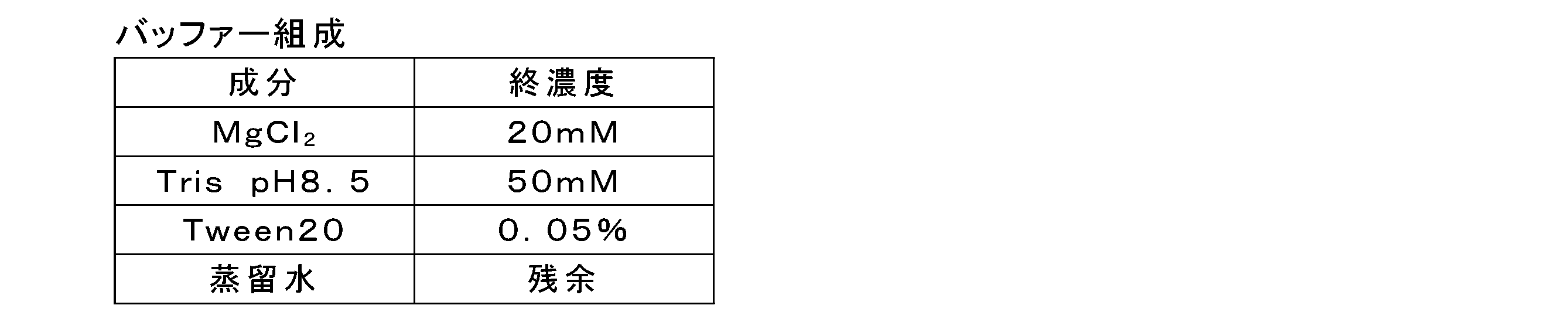
バッファーの注入は、各流体デバイスを、基板側から顕微鏡(品番「BZ-710」、キーエンス社製)を用いて明視野観察しながら行った。10倍の対物レンズを使用し、露光時間は、20ミリ秒とした。そして、ウェル内の気泡が完全に除去されるまでに要したバッファーの送液量を測定した。
図2の(a)及び(b)に、実施例1の流体デバイスにバッファーを送液した場合のウェルアレイの明視野観察結果を示す写真である。図2の(a)は、バッファーを20μL送液した結果を示す写真であり、図2の(b)は、バッファーを50μL送液した結果を示す写真である。図2の(a)及び(b)の観察画像のサイズは、3,600μm×2,700μmであった。その結果、実施例1の流体デバイスは、バッファー50μLの送液量で、ウェル内に残存していた気泡を十分に除去することができた。
また、図3の(a)~(c)に、比較例1の流体デバイスにバッファーを送液した場合のウェルアレイの明視野観察結果を示す写真である。図3の(a)はバッファーを100μL送液した結果を示す写真であり、図3の(b)はバッファーを200μL送液した結果を示す写真であり、図3の(c)はバッファーを300μL送液した結果を示す写真である。図3の(a)~(c)の観察画像のサイズは、3,600μm×2,700μmであった。その結果、比較例1の流体デバイスは、ウェル内に残存していた気泡を十分に除去するのにバッファー300μLの送液が必要であった。
また、図4の(a)~(e)に、比較例2の流体デバイスにバッファーを送液した場合のウェルアレイの明視野観察結果を示写真である。図4の(a)はバッファーを100μL送液した結果を示す写真であり、図4の(b)はバッファーを200μL送液した結果を示す写真であり、図4の(c)はバッファーを300μL送液した結果を示す写真であり、図4の(d)はバッファーを400μL送液した結果を示す写真であり、図4の(e)はバッファーを500μL送液した結果を示す写真である。図4の(a)~(e)の観察画像のサイズは、3,600μm×2,700μmであった。その結果、比較例2の流体デバイスは、ウェル内に残存していた気泡を十分に除去するのにバッファー500μLの送液が必要であった。
下記表2に、各流体デバイスのウェルの直径、ウェルの深さ、ウェルの中心と当該ウェルに最も近接するウェルの中心との間の距離(中心間距離)、中心間距離に対するウェルの直径の割合(直径/中心間距離)、流路高さ、開口面積比率、ウェル内の気泡が完全に除去されるまでに要したバッファーの送液量、及びウェル内の気泡の残留しにくさの評価結果を示す。
開口面積比率は、ウェルアレイが形成されている6.0mm×30.0mmの領域の面積に対する、ウェルの開口部の面積の合計の割合とした。また、ウェル内の気泡の残留しにくさの評価結果は、以下の評価基準で評価した。
(評価基準)
良好:ウェル内の気泡が完全に除去されるまでに要したバッファーの送液量が50μL以下
不良:ウェル内の気泡が完全に除去されるまでに要したバッファーの送液量が50μL超
(評価基準)
良好:ウェル内の気泡が完全に除去されるまでに要したバッファーの送液量が50μL以下
不良:ウェル内の気泡が完全に除去されるまでに要したバッファーの送液量が50μL超

以上の結果から、ウェルの中心と当該ウェルに最も近接するウェルの中心との間の距離(中心間距離)に対するウェルの直径の割合(直径/中心間距離)が、0.8以上であるとウェル内に気泡が残留しにくい傾向が明らかとなった。
[実験例2]
(シミュレーション1)
シミュレーションにより、流体デバイスのウェル内の気泡の残留しにくさを検討した。シミュレーションにはソフトウエア(製品名「Ansys Fluent」、ANSYS社製)を使用した。
(シミュレーション1)
シミュレーションにより、流体デバイスのウェル内の気泡の残留しにくさを検討した。シミュレーションにはソフトウエア(製品名「Ansys Fluent」、ANSYS社製)を使用した。
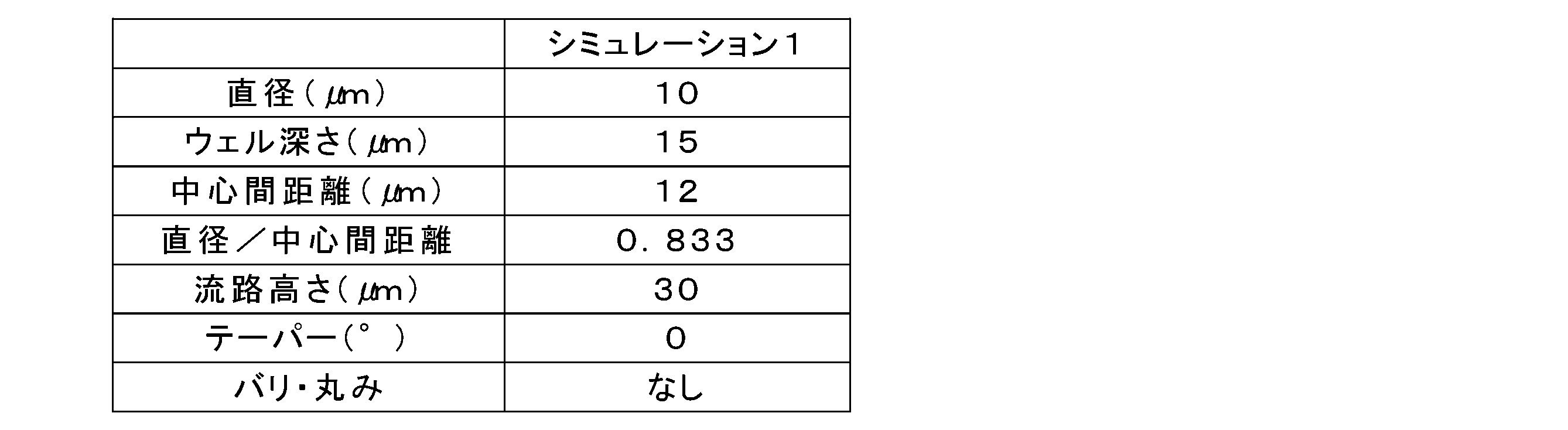
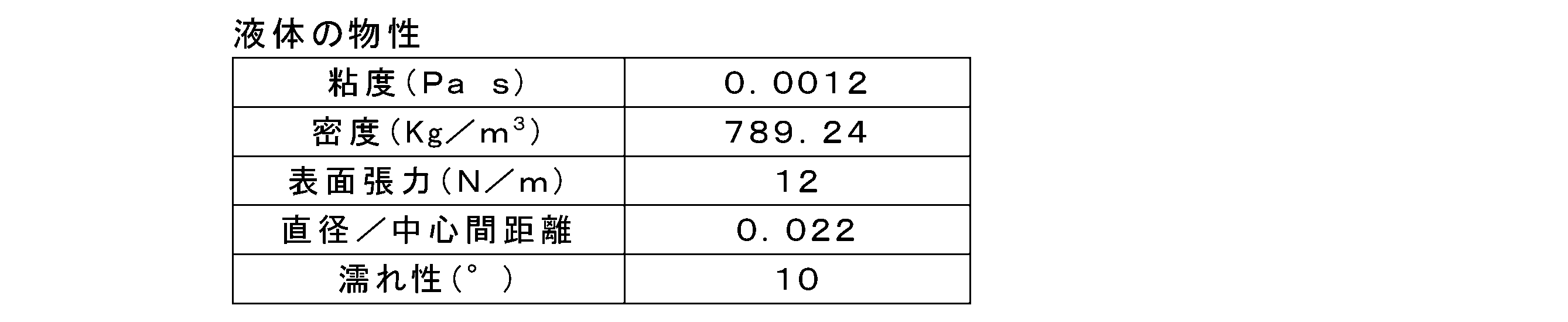
下記表3に示す形状のウェルアレイを有する流体デバイスの流路に下記表4に示す物性の液体を送液した場合についてシミュレーションした。下記表3に、流体デバイスのウェルの直径、ウェルの深さ、ウェルの中心と当該ウェルに最も近接するウェルの中心との間の距離(中心間距離)、中心間距離に対するウェルの直径の割合(直径/中心間距離)、流路高さ、テーパー、及びバリ・丸みの有無を示す。下記表4中、濡れ性は、流体デバイスの物性を反映した値を示す。なお、テーパーとは、ウェルの開口部とウェルの底部の面積が異なり、開口部から底部に向かって先細りになっている形状を意味する。テーパー角とは、ウェルの開口部を含む基板の一面とウェルの側面の角度を示し、テーパー角が0°であるとき、ウェルの開口部を含む基板の一面とウェルの側面の角度は、90°である。
本実験例でシミュレーションを行った流体デバイスは、実施例1の流体デバイスに相当するものであった。
シミュレーションは、送液開始から0.027秒後まで流速33mm/秒で液体を送液し、0.027秒後から0.047秒後まで流速330mm/秒で液体を送液した場合について行った。
図5の(a)~(e)は、シミュレーションの結果を示す流体デバイスの断面図である。図5の(a)は、送液開始前のシミュレーション結果であり、図5の(b)は、送液開始0.02秒後のシミュレーション結果であり、図5の(c)は、送液開始0.03秒後のシミュレーション結果であり、図5の(d)は、送液開始0.04秒後のシミュレーション結果であり、図5の(e)は、送液開始0.047秒後のシミュレーション結果である。図5の(a)~(e)中、スケールは、気泡及び液体の輪郭を示す。
その結果、送液開始後、ウェル内の気泡が集まって合体し、合体した気泡が他の気泡を巻き込みながら流れていくことが明らかとなった。
[実験例3]
(シミュレーション2)
シミュレーションにより、流体デバイスのウェル内の気泡の残留しにくさを検討した。シミュレーションにはソフトウエア(製品名「Ansys Fluent」、ANSYS社製)を使用した。
(シミュレーション2)
シミュレーションにより、流体デバイスのウェル内の気泡の残留しにくさを検討した。シミュレーションにはソフトウエア(製品名「Ansys Fluent」、ANSYS社製)を使用した。
下記表5に示す形状のウェルアレイを有する流体デバイスの流路に上記表4に示す物性の液体を送液した場合についてシミュレーションした。
本実験例でシミュレーションを行った流体デバイスは、比較例1の流体デバイスに相当するものであった。
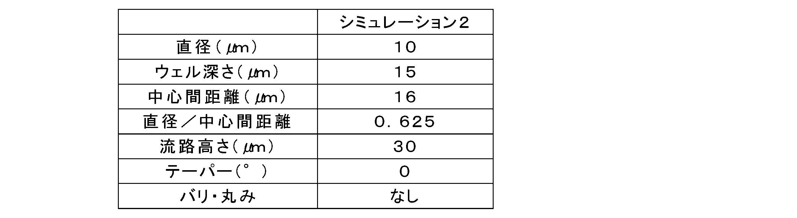
シミュレーションは、送液開始から0.02秒後まで流速33mm/秒で液体を送液し、0.02秒後から流速330mm/秒で液体を送液した場合について行った。
図6の(a)~(c)は、シミュレーションの結果を示す流体デバイスの断面図である。図6の(a)は、送液開始前のシミュレーション結果であり、図6の(b)は、送液開始0.02秒後のシミュレーション結果であり、図6の(c)は送液開始0.03秒後のシミュレーション結果である。図6の(a)~(c)中、スケールは、気泡及び液体の輪郭を示す。
その結果、送液を行っても、ウェル内の気泡が集まって合体することはなく、気泡が残留することが明らかとなった。
[実験例4]
(シミュレーション3)
シミュレーションにより、流体デバイスのウェル内の気泡の残留しにくさを検討した。シミュレーションにはソフトウエア(製品名「Ansys Fluent」、ANSYS社製)を使用した。
(シミュレーション3)
シミュレーションにより、流体デバイスのウェル内の気泡の残留しにくさを検討した。シミュレーションにはソフトウエア(製品名「Ansys Fluent」、ANSYS社製)を使用した。
下記表6に示す形状のウェルアレイを有する流体デバイスの流路に上記表4に示す物性の液体を送液した場合についてシミュレーションした。

シミュレーションは、送液開始から0.02秒後まで流速33mm/秒で液体を送液した場合について行った。
図7の(a)~(c)は、シミュレーションの結果を示す流体デバイスの断面図である。図7の(a)は、送液開始前のシミュレーション結果であり、図7の(b)は、送液開始0.01秒後のシミュレーション結果であり、図7の(c)は、送液開始0.02秒後のシミュレーション結果である。図7の(a)~(c)中、スケールは気泡及び液体の輪郭を示す。
その結果、ウェルの直径が大きいと、ウェル内に気泡が残留しにくいことが明らかとなった。
[実験例5]
(シミュレーション4)
シミュレーションにより、流体デバイスのウェル内の気泡の残留しにくさを検討した。シミュレーションにはソフトウエア(製品名「Ansys Fluent」、ANSYS社製)を使用した。
(シミュレーション4)
シミュレーションにより、流体デバイスのウェル内の気泡の残留しにくさを検討した。シミュレーションにはソフトウエア(製品名「Ansys Fluent」、ANSYS社製)を使用した。
下記表7に示す形状のウェルアレイを有する流体デバイスの流路に上記表4に示す物性の液体を送液した場合についてシミュレーションした。
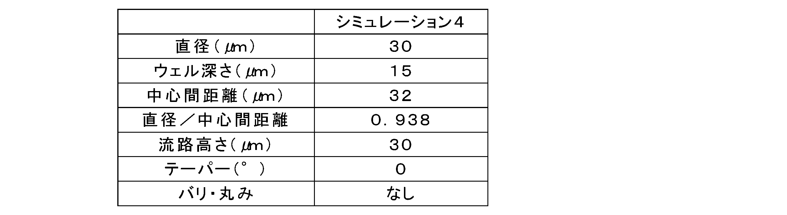
シミュレーションは、送液開始から0.02秒後まで流速33mm/秒で液体を送液した場合について行った。
図8の(a)~(c)は、シミュレーションの結果を示す流体デバイスの断面図である。図8の(a)は、送液開始前のシミュレーション結果であり、図8の(b)は、送液開始0.01秒後のシミュレーション結果であり、図8(c)は、送液開始0.02秒後のシミュレーション結果である。図8の(a)~(c)中、スケールは気泡及び液体の輪郭を示す。
その結果、ウェルの直径が大きいと、ウェル内に気泡が残留しにくいことが明らかとなった。
本発明によれば、ウェルアレイを有する流体デバイスの各ウェルに水性媒体を導入する場合に、ウェル内部の気泡の残留を抑制する技術を提供することができる。また、本発明の検出対象を検出する方法によれば、ウェルアレイを有する流体デバイスの各ウェルに水性媒体を導入して隔離し、シグナルを生じさせて検出する場合に、ウェル内部の気泡の残留を抑制し、検出対象の検出効率を向上させることができる。
100…流体デバイス、110…ウェル、120ウェルアレイ、130…基板、140…蓋部材、131,141…面、150…流路、160…導入口、170…排出口、180…周縁部材、A,B,C…ウェル、Da…直径、Dab…距離、Ca,Cb,Cc…重心。
Claims (14)
- 一方面に開口する複数の同一形状のウェルが規則的に配置されたウェルアレイを少なくとも一部に有する基板と、
前記ウェルアレイと対向して配置された蓋部材と、を備え、
前記ウェルアレイと前記蓋部材との間の空間は流体が流れる流路を形成しており、
前記ウェルアレイの任意のウェルAの開口部の重心Caと、前記ウェルAに最も近接するウェルBの開口部の重心Cbとの間の距離Dabと、前記ウェルAの開口部の面積と同面積の円の直径Daとが、下記式(1)を満たす、流体デバイス。
0.8≦Da/Dab<1 …(1) - 前記ウェルの開口部の面積と同面積の円の直径が、1μm以上50μm以下である、請求項1に記載の流体デバイス。
- 前記一方面におけるウェルアレイの面積に対する、前記ウェルアレイの各ウェルの開口部の面積の合計の割合が、30%以上90%以下である、請求項1又は2に記載の流体デバイス。
- 前記ウェル1つあたりの容積が10fL以上100pL以下である、請求項1~3のいずれか一項に記載の流体デバイス。
- 前記ウェルアレイの各ウェルの容積の合計が0.2μL以上2.0μL以下である、請求項1~4のいずれか一項に記載の流体デバイス。
- 前記流路の容積に対する、前記ウェルアレイの各ウェルの容積の合計の割合が5%以上40%以下である、請求項1~5のいずれか一項に記載の流体デバイス。
- 前記ウェルの深さに対する、前記ウェルの開口部の面積と同面積の円の直径の割合が3%以上200%以下である、請求項1~6のいずれか一項に記載の流体デバイス。
- 前記一方面の水との接触角が70度以上180度以下である、請求項1~7のいずれか一項に記載の流体デバイス。
- 前記蓋部材の前記ウェルアレイに対向する面の水との接触角が70度以上180度以下である、請求項1~8のいずれか一項に記載の流体デバイス。
- 請求項1~9のいずれか一項に記載の流体デバイスの前記流路に水性媒体を導入する工程と、
前記水性媒体を導入した後に、前記流路に封止液を導入して前記水性媒体を前記ウェルアレイの各ウェルに隔離する工程と、を含む、前記水性媒体の隔離方法。 - 請求項10に記載の方法により検出対象及び検出試薬を含む水性媒体を隔離した後に、前記流体デバイスを加熱して前記ウェルの内部で反応を生じさせ、前記検出対象を検出するためのシグナルを生じさせる工程と、
前記シグナルを検出する工程と、を含む、前記検出対象を検出する方法。 - 前記検出対象が生体分子である、請求項11に記載の方法。
- 前記反応が定温反応である、請求項11又は12に記載の方法。
- 前記シグナルが蛍光である、請求項11~13のいずれか一項に記載の方法。
Priority Applications (4)
| Application Number | Priority Date | Filing Date | Title |
|---|---|---|---|
| CN202180050710.3A CN116057386B (zh) | 2020-09-02 | 2021-08-31 | 流体设备及其用途 |
| EP21864305.4A EP4209786A4 (en) | 2020-09-02 | 2021-08-31 | FLUID DEVICE AND ITS USE |
| JP2022546323A JP7831297B2 (ja) | 2020-09-02 | 2021-08-31 | 流体デバイス及びその使用 |
| US18/116,411 US20230201826A1 (en) | 2020-09-02 | 2023-03-02 | Fluidic device and use of the same |
Applications Claiming Priority (2)
| Application Number | Priority Date | Filing Date | Title |
|---|---|---|---|
| JP2020-147507 | 2020-09-02 | ||
| JP2020147507 | 2020-09-02 |
Related Child Applications (1)
| Application Number | Title | Priority Date | Filing Date |
|---|---|---|---|
| US18/116,411 Continuation US20230201826A1 (en) | 2020-09-02 | 2023-03-02 | Fluidic device and use of the same |
Publications (1)
| Publication Number | Publication Date |
|---|---|
| WO2022050247A1 true WO2022050247A1 (ja) | 2022-03-10 |
Family
ID=80492245
Family Applications (1)
| Application Number | Title | Priority Date | Filing Date |
|---|---|---|---|
| PCT/JP2021/031830 Ceased WO2022050247A1 (ja) | 2020-09-02 | 2021-08-31 | 流体デバイス及びその使用 |
Country Status (5)
| Country | Link |
|---|---|
| US (1) | US20230201826A1 (ja) |
| EP (1) | EP4209786A4 (ja) |
| JP (1) | JP7831297B2 (ja) |
| CN (1) | CN116057386B (ja) |
| WO (1) | WO2022050247A1 (ja) |
Cited By (1)
| Publication number | Priority date | Publication date | Assignee | Title |
|---|---|---|---|---|
| WO2025094815A1 (ja) * | 2023-10-30 | 2025-05-08 | Toppanホールディングス株式会社 | 流体デバイス |
Citations (6)
| Publication number | Priority date | Publication date | Assignee | Title |
|---|---|---|---|---|
| JP2007525647A (ja) * | 2003-04-30 | 2007-09-06 | オーロラ ディスカバリー インコーポレイティッド | 高密度保存およびアッセイプラットフォームを提供するマルチウェルプレート |
| WO2015115635A1 (ja) * | 2014-01-31 | 2015-08-06 | 凸版印刷株式会社 | 生体分子解析キット及び生体分子解析方法 |
| WO2016072416A1 (ja) * | 2014-11-04 | 2016-05-12 | 凸版印刷株式会社 | 核酸導入方法、核酸検出方法、生体成分解析方法、生体成分定量用アレイデバイス、及び生体成分解析キット |
| WO2017115863A1 (ja) * | 2015-12-28 | 2017-07-06 | 凸版印刷株式会社 | マイクロ流体デバイスおよび観察方法 |
| WO2019046307A1 (en) * | 2017-08-29 | 2019-03-07 | Celsee Diagnostics, Inc. | SYSTEM AND METHOD FOR ISOLATING AND ANALYZING CELLS |
| JP2020147507A (ja) | 2019-03-11 | 2020-09-17 | シトリンファンデーション リミテッドCitrin Foundation Ltd. | シトリン欠損症治療剤 |
Family Cites Families (3)
| Publication number | Priority date | Publication date | Assignee | Title |
|---|---|---|---|---|
| US6485690B1 (en) * | 1999-05-27 | 2002-11-26 | Orchid Biosciences, Inc. | Multiple fluid sample processor and system |
| KR20150010939A (ko) * | 2012-03-16 | 2015-01-29 | 라이프 테크놀로지스 코포레이션 | 생물학적 샘플을 평가하기 위한 시스템 및 방법 |
| WO2017188441A1 (ja) * | 2016-04-28 | 2017-11-02 | 凸版印刷株式会社 | 解析デバイス、解析キット、及び解析システム |
-
2021
- 2021-08-31 JP JP2022546323A patent/JP7831297B2/ja active Active
- 2021-08-31 CN CN202180050710.3A patent/CN116057386B/zh active Active
- 2021-08-31 EP EP21864305.4A patent/EP4209786A4/en active Pending
- 2021-08-31 WO PCT/JP2021/031830 patent/WO2022050247A1/ja not_active Ceased
-
2023
- 2023-03-02 US US18/116,411 patent/US20230201826A1/en active Pending
Patent Citations (6)
| Publication number | Priority date | Publication date | Assignee | Title |
|---|---|---|---|---|
| JP2007525647A (ja) * | 2003-04-30 | 2007-09-06 | オーロラ ディスカバリー インコーポレイティッド | 高密度保存およびアッセイプラットフォームを提供するマルチウェルプレート |
| WO2015115635A1 (ja) * | 2014-01-31 | 2015-08-06 | 凸版印刷株式会社 | 生体分子解析キット及び生体分子解析方法 |
| WO2016072416A1 (ja) * | 2014-11-04 | 2016-05-12 | 凸版印刷株式会社 | 核酸導入方法、核酸検出方法、生体成分解析方法、生体成分定量用アレイデバイス、及び生体成分解析キット |
| WO2017115863A1 (ja) * | 2015-12-28 | 2017-07-06 | 凸版印刷株式会社 | マイクロ流体デバイスおよび観察方法 |
| WO2019046307A1 (en) * | 2017-08-29 | 2019-03-07 | Celsee Diagnostics, Inc. | SYSTEM AND METHOD FOR ISOLATING AND ANALYZING CELLS |
| JP2020147507A (ja) | 2019-03-11 | 2020-09-17 | シトリンファンデーション リミテッドCitrin Foundation Ltd. | シトリン欠損症治療剤 |
Non-Patent Citations (1)
| Title |
|---|
| See also references of EP4209786A4 |
Cited By (1)
| Publication number | Priority date | Publication date | Assignee | Title |
|---|---|---|---|---|
| WO2025094815A1 (ja) * | 2023-10-30 | 2025-05-08 | Toppanホールディングス株式会社 | 流体デバイス |
Also Published As
| Publication number | Publication date |
|---|---|
| CN116057386B (zh) | 2026-04-14 |
| EP4209786A1 (en) | 2023-07-12 |
| EP4209786A4 (en) | 2024-02-28 |
| JPWO2022050247A1 (ja) | 2022-03-10 |
| CN116057386A (zh) | 2023-05-02 |
| US20230201826A1 (en) | 2023-06-29 |
| JP7831297B2 (ja) | 2026-03-17 |
Similar Documents
| Publication | Publication Date | Title |
|---|---|---|
| JP3749991B2 (ja) | 微量液体秤取構造及び該構造を有するマイクロチップ | |
| JP6483118B2 (ja) | マイクロチャンバープレート | |
| AU2003243080B2 (en) | Micro fluidic structures | |
| US10718776B2 (en) | Method for detecting biological substance | |
| US20050042770A1 (en) | Fluidic functions based on non-wettable surfaces | |
| JP2002502955A (ja) | 高スループットスクリーニングアッセイ用仮想ウェル | |
| US20080317632A1 (en) | Microchannel and Microfluid Chip | |
| JP2009524825A (ja) | 流体ドロップレットの合体 | |
| CN109070080A (zh) | 颗粒分离装置和颗粒分离方法 | |
| JP2008064748A (ja) | 微量液体秤取装置、それを有するマイクロチップ及び微量な液体の秤取方法 | |
| US10139323B2 (en) | Apparatus for separating micro-particles | |
| JP2017072476A (ja) | マイクロウェルアレイ、マイクロ流体デバイス、マイクロウェルアレイのウェル内に水性液体を封入する方法及びマイクロウェルアレイの製造方法 | |
| CN103003450A (zh) | 样本内装微腔板及分析用微腔板的制造方法、分析用微腔板及样本内装微腔板制造装置套件 | |
| JP2024109978A (ja) | マイクロ流体デバイスおよび試料分析方法 | |
| JP2022531688A (ja) | ナノ容器を含むアッセイプレート及びサンプル回収アセンブリ | |
| WO2022050247A1 (ja) | 流体デバイス及びその使用 | |
| JP6821947B2 (ja) | 粒子の収容方法、及び、粒子の封入方法 | |
| KR102036922B1 (ko) | 분석 모듈 및 이의 제조 방법 | |
| JP2013208127A (ja) | マイクロ反応容器及びマイクロ反応容器を用いたポリメラーゼ連鎖反応方法 | |
| JP2024129127A (ja) | ウェルに液体を導入する方法 | |
| JP4892217B2 (ja) | 反応チップおよび物質の検出方法 | |
| Paul et al. | A “dry and wet hybrid” lithography technique for multilevel replication templates: Applications to microfluidic neuron culture and two-phase global mixing | |
| JP7337760B2 (ja) | 生体分子の分析方法 | |
| JP2006254838A (ja) | 検出チップ及びこれを用いた物質の検出方法 | |
| US20060088449A1 (en) | Systems and methods for transferring a fluid sample |
Legal Events
| Date | Code | Title | Description |
|---|---|---|---|
| 121 | Ep: the epo has been informed by wipo that ep was designated in this application |
Ref document number: 21864305 Country of ref document: EP Kind code of ref document: A1 |
|
| ENP | Entry into the national phase |
Ref document number: 2022546323 Country of ref document: JP Kind code of ref document: A |
|
| NENP | Non-entry into the national phase |
Ref country code: DE |
|
| ENP | Entry into the national phase |
Ref document number: 2021864305 Country of ref document: EP Effective date: 20230403 |