WO2022050378A1 - Fluoropolymer and liquid crystal polymer blend - Google Patents
Fluoropolymer and liquid crystal polymer blend Download PDFInfo
- Publication number
- WO2022050378A1 WO2022050378A1 PCT/JP2021/032446 JP2021032446W WO2022050378A1 WO 2022050378 A1 WO2022050378 A1 WO 2022050378A1 JP 2021032446 W JP2021032446 W JP 2021032446W WO 2022050378 A1 WO2022050378 A1 WO 2022050378A1
- Authority
- WO
- WIPO (PCT)
- Prior art keywords
- polymer blend
- lcp
- polymer
- blend
- fep
- Prior art date
- Legal status (The legal status is an assumption and is not a legal conclusion. Google has not performed a legal analysis and makes no representation as to the accuracy of the status listed.)
- Ceased
Links
Images













Classifications
-
- C—CHEMISTRY; METALLURGY
- C09—DYES; PAINTS; POLISHES; NATURAL RESINS; ADHESIVES; COMPOSITIONS NOT OTHERWISE PROVIDED FOR; APPLICATIONS OF MATERIALS NOT OTHERWISE PROVIDED FOR
- C09K—MATERIALS FOR MISCELLANEOUS APPLICATIONS, NOT PROVIDED FOR ELSEWHERE
- C09K19/00—Liquid crystal materials
- C09K19/04—Liquid crystal materials characterised by the chemical structure of the liquid crystal components, e.g. by a specific unit
- C09K19/06—Non-steroidal liquid crystal compounds
- C09K19/08—Non-steroidal liquid crystal compounds containing at least two non-condensed rings
- C09K19/10—Non-steroidal liquid crystal compounds containing at least two non-condensed rings containing at least two benzene rings
- C09K19/12—Non-steroidal liquid crystal compounds containing at least two non-condensed rings containing at least two benzene rings at least two benzene rings directly linked, e.g. biphenyls
-
- C—CHEMISTRY; METALLURGY
- C08—ORGANIC MACROMOLECULAR COMPOUNDS; THEIR PREPARATION OR CHEMICAL WORKING-UP; COMPOSITIONS BASED THEREON
- C08G—MACROMOLECULAR COMPOUNDS OBTAINED OTHERWISE THAN BY REACTIONS ONLY INVOLVING UNSATURATED CARBON-TO-CARBON BONDS
- C08G63/00—Macromolecular compounds obtained by reactions forming a carboxylic ester link in the main chain of the macromolecule
- C08G63/68—Polyesters containing atoms other than carbon, hydrogen and oxygen
- C08G63/682—Polyesters containing atoms other than carbon, hydrogen and oxygen containing halogens
- C08G63/6822—Polyesters containing atoms other than carbon, hydrogen and oxygen containing halogens derived from hydroxy carboxylic acids
-
- C—CHEMISTRY; METALLURGY
- C08—ORGANIC MACROMOLECULAR COMPOUNDS; THEIR PREPARATION OR CHEMICAL WORKING-UP; COMPOSITIONS BASED THEREON
- C08G—MACROMOLECULAR COMPOUNDS OBTAINED OTHERWISE THAN BY REACTIONS ONLY INVOLVING UNSATURATED CARBON-TO-CARBON BONDS
- C08G63/00—Macromolecular compounds obtained by reactions forming a carboxylic ester link in the main chain of the macromolecule
- C08G63/02—Polyesters derived from hydroxycarboxylic acids or from polycarboxylic acids and polyhydroxy compounds
- C08G63/06—Polyesters derived from hydroxycarboxylic acids or from polycarboxylic acids and polyhydroxy compounds derived from hydroxycarboxylic acids
- C08G63/065—Polyesters derived from hydroxycarboxylic acids or from polycarboxylic acids and polyhydroxy compounds derived from hydroxycarboxylic acids the hydroxy and carboxylic ester groups being bound to aromatic rings
-
- C—CHEMISTRY; METALLURGY
- C08—ORGANIC MACROMOLECULAR COMPOUNDS; THEIR PREPARATION OR CHEMICAL WORKING-UP; COMPOSITIONS BASED THEREON
- C08L—COMPOSITIONS OF MACROMOLECULAR COMPOUNDS
- C08L27/00—Compositions of homopolymers or copolymers of compounds having one or more unsaturated aliphatic radicals, each having only one carbon-to-carbon double bond, and at least one being terminated by a halogen; Compositions of derivatives of such polymers
- C08L27/02—Compositions of homopolymers or copolymers of compounds having one or more unsaturated aliphatic radicals, each having only one carbon-to-carbon double bond, and at least one being terminated by a halogen; Compositions of derivatives of such polymers not modified by chemical after-treatment
- C08L27/12—Compositions of homopolymers or copolymers of compounds having one or more unsaturated aliphatic radicals, each having only one carbon-to-carbon double bond, and at least one being terminated by a halogen; Compositions of derivatives of such polymers not modified by chemical after-treatment containing fluorine atoms
-
- C—CHEMISTRY; METALLURGY
- C08—ORGANIC MACROMOLECULAR COMPOUNDS; THEIR PREPARATION OR CHEMICAL WORKING-UP; COMPOSITIONS BASED THEREON
- C08L—COMPOSITIONS OF MACROMOLECULAR COMPOUNDS
- C08L67/00—Compositions of polyesters obtained by reactions forming a carboxylic ester link in the main chain; Compositions of derivatives of such polymers
- C08L67/02—Polyesters derived from dicarboxylic acids and dihydroxy compounds
- C08L67/03—Polyesters derived from dicarboxylic acids and dihydroxy compounds the dicarboxylic acids and dihydroxy compounds having the carboxyl- and the hydroxy groups directly linked to aromatic rings
-
- C—CHEMISTRY; METALLURGY
- C09—DYES; PAINTS; POLISHES; NATURAL RESINS; ADHESIVES; COMPOSITIONS NOT OTHERWISE PROVIDED FOR; APPLICATIONS OF MATERIALS NOT OTHERWISE PROVIDED FOR
- C09K—MATERIALS FOR MISCELLANEOUS APPLICATIONS, NOT PROVIDED FOR ELSEWHERE
- C09K19/00—Liquid crystal materials
- C09K19/04—Liquid crystal materials characterised by the chemical structure of the liquid crystal components, e.g. by a specific unit
- C09K19/06—Non-steroidal liquid crystal compounds
- C09K19/062—Non-steroidal liquid crystal compounds containing one non-condensed benzene ring
-
- C—CHEMISTRY; METALLURGY
- C09—DYES; PAINTS; POLISHES; NATURAL RESINS; ADHESIVES; COMPOSITIONS NOT OTHERWISE PROVIDED FOR; APPLICATIONS OF MATERIALS NOT OTHERWISE PROVIDED FOR
- C09K—MATERIALS FOR MISCELLANEOUS APPLICATIONS, NOT PROVIDED FOR ELSEWHERE
- C09K19/00—Liquid crystal materials
- C09K19/52—Liquid crystal materials characterised by components which are not liquid crystals, e.g. additives with special physical aspect: solvents, solid particles
- C09K19/54—Additives having no specific mesophase characterised by their chemical composition
- C09K19/542—Macromolecular compounds
-
- C—CHEMISTRY; METALLURGY
- C09—DYES; PAINTS; POLISHES; NATURAL RESINS; ADHESIVES; COMPOSITIONS NOT OTHERWISE PROVIDED FOR; APPLICATIONS OF MATERIALS NOT OTHERWISE PROVIDED FOR
- C09K—MATERIALS FOR MISCELLANEOUS APPLICATIONS, NOT PROVIDED FOR ELSEWHERE
- C09K19/00—Liquid crystal materials
- C09K19/04—Liquid crystal materials characterised by the chemical structure of the liquid crystal components, e.g. by a specific unit
- C09K19/06—Non-steroidal liquid crystal compounds
- C09K19/08—Non-steroidal liquid crystal compounds containing at least two non-condensed rings
- C09K19/10—Non-steroidal liquid crystal compounds containing at least two non-condensed rings containing at least two benzene rings
- C09K19/12—Non-steroidal liquid crystal compounds containing at least two non-condensed rings containing at least two benzene rings at least two benzene rings directly linked, e.g. biphenyls
- C09K2019/121—Compounds containing phenylene-1,4-diyl (-Ph-)
- C09K2019/122—Ph-Ph
-
- C—CHEMISTRY; METALLURGY
- C09—DYES; PAINTS; POLISHES; NATURAL RESINS; ADHESIVES; COMPOSITIONS NOT OTHERWISE PROVIDED FOR; APPLICATIONS OF MATERIALS NOT OTHERWISE PROVIDED FOR
- C09K—MATERIALS FOR MISCELLANEOUS APPLICATIONS, NOT PROVIDED FOR ELSEWHERE
- C09K19/00—Liquid crystal materials
- C09K19/52—Liquid crystal materials characterised by components which are not liquid crystals, e.g. additives with special physical aspect: solvents, solid particles
- C09K19/54—Additives having no specific mesophase characterised by their chemical composition
- C09K19/542—Macromolecular compounds
- C09K2019/546—Macromolecular compounds creating a polymeric network
Definitions
- the present disclosure relates generally to polymer blends, methods of making polymer blends, methods of using polymer blends, compatibilizer compositions for use with polymer blends, and articles manufactured from polymer blends.
- PCBs are integral components of many electronics. PCBs mechanically support and electrically connect electrical components using conductive tracks etched from sheet layers of copper laminated onto and/or between sheet layers of a non-conductive substrate.
- a PCB can be rigid, flexible, or rigid-flexible, and contain multiple laminates, each made of thermoplastic or thermoset polymeric materials. The materials used for the laminates in PCBs are often ranked by the value of their dielectric constant (Dk) and their dissipation factor (Df). The highest performing materials have the lowest Dk and Df.
- Dk dielectric constant
- Df dissipation factor
- Low Dk values and low Df values are useful properties for high speed digital and high frequency PCBs that are used in a variety of emerging markets, such as autonomous driving and fifth generation wireless communication (5G) devices (for example, radio frequency components, power amplifiers, and antennas).
- 5G fifth generation wireless communication
- Low Dissipation Factor Df thermoplastic laminates are used in high frequency PCBs to enable high power applications and reduce the loss of energy generated by heat, which can degrade the quality of the signal.
- Low Dielectric Constant Dk laminates are also important in high speed digital PCBs for enabling rapid signal propagation.
- Fluoropolymers generally have excellent heat and chemical resistance and non-stick properties. While fluoropolymers exhibit excellent chemical properties, they have relatively weak mechanical properties when compared to specialty materials used in high performance PCB applications, such as liquid crystal polymers (LCPs) and polyimide (PI). Fluoropolymers also exhibit low surface energy and high coefficient of thermal expansion (CTE), which make it difficult to integrate these materials into PCB laminates.
- LCPs liquid crystal polymers
- PI polyimide
- CTE coefficient of thermal expansion
- the present disclosure describes a blend of LCP and FP that addresses the problems described above by providing superior properties to either of LCP or FP.
- a compatibilizer composition is described for use in such blends.
- Some embodiments of the LCP/FP blend form a thermoplastic alloy with significantly enhanced mechanical properties, significantly reduced coefficient of thermal expansion, while maintaining thermal properties and improved electrical properties (specifically dielectric constant and dissipation factor) over the liquid crystal polymer.
- a copolymer of a fluorine-containing monomer and a liquid crystal monomer is provided.
- a compatibilizer composition comprising: a copolymer of a fluorine-containing monomer and a liquid crystal monomer.
- a polymer blend comprising: a fluoropolymer, a liquid crystal polymer, and a compatibilizer composition, wherein the compatibilizer composition contains a copolymer having a fluorinated or non-fluorinated monomer and a liquid crystal monomer.
- a process for producing a compatibilizer composition comprising: making a copolymer by mixing a fluoropolymer with a functionalized fluorinated molecule and a liquid crystal monomer; and making the compatibilizer composition by mixing the fully fluorinated fluoropolymer, fluorinated molecule, and liquid crystal monomer in an extruder.
- a process for producing a compatibilizer composition comprising: making a copolymer by mixing a non-fluorinated polymer with a liquid crystal monomer, and making the compatibilizer composition by mixing the copolymer constituents in an extruder.
- a process for producing a compatibilized blend of a liquid crystal polymer (LCP) and a fluoropolymer (FP) comprising: combining the LCP and the FP with a compatibilizer composition comprising a copolymer of a fluorine-containing molecule and a liquid crystal monomer.
- a compatibilizer composition is provided that is a product of the process comprising: making a copolymer by mixing the fully fluorinated fluoropolymer with the fluorinated molecule and the liquid crystal monomer; and making the compatibilizer composition by mixing the copolymer blend in an extruder.
- a compatibilizer composition is provided that is a product of the process comprising: making a copolymer by mixing a non-fluorinated polymer with a liquid crystal monomer, and making the compatibilizer composition by mixing the copolymer constituents in an extruder.
- a compatibilized blend of a liquid crystal polymer (LCP) and a fluoropolymer (FP) is provided that is the product of the process comprising: combining the LCP and the FP with a compatibilizer composition comprising a copolymer of a fluorine-containing molecule and a liquid crystal monomer.
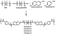
- FIG. 1 An example of a scheme for producing a compatibilizer composition or a reactive polymer compatibilizer containing FEP.
- FIG. 2. Scanning electron micrograph image of an embodiment of the reactive polymer compatibilizer at 1500x magnification.
- FIG. 3. Scanning electron micrograph image of an embodiment of the reactive polymer compatibilizer at 2000x magnification.
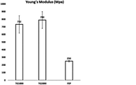
- FIG. 4. Tensile modulus of FEP, LCP, and an embodiment of blended FEP and LCP.
- FIG. 5. Coefficient of thermal expansion (CTE) at 100°C of FEP, LCP, and an embodiment of blended FEP and LCP.
- FIG. 6. Thermal stability as measured by loss in nitrogen of FEP, LCP, and an embodiment of blended FEP and LCP.
- Y axis is the temperature at which 5% weight loss was observed.
- FIG. 8 Flexural stress at maximum flexure load of FEP, LCP, and an embodiment of blended FEP and LCP. Note that the maximum flexure load of the blend is lower than for the unblended LCP.
- FIG. 9. Flexural modulus of FEP, LCP, and an embodiment of blended FEP and LCP. Note that the flexural modulus of the blend is lower than for the unblended LCP.
- FIG. 10. Maximum tensile strength of thin film made from embodiments of the FEP and LCP blend as compared to FEP alone.
- FIG. 13 Flexural modulus of thin film made from embodiments of the FEP and LCP blend as compared to FEP alone.
- FIG. 14 Coefficient of thermal expansion of thin film made from embodiments of the FEP and LCP blend as compared to FEP alone at five temperatures.
- FIG. 15. An example of a scheme for producing a reactive polymer compatibilizer containing PFA.
- FIG. 16. Examples of cyclic olefin copolymer structures.
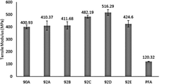
- FIG. 17. Tensile strength of LCP and FP blends according to certain embodiments.
- FIG. 20 CTE of LCP and FP blends according to certain embodiments.
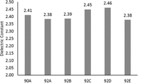
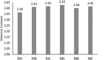
- FIG. 21 Dielectric constant of LCP and FP blends according to certain embodiments.
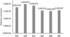
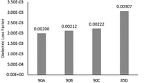
- FIG. 22 Dielectric loss factor of LCP and FP blends according to certain embodiments.
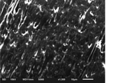
- FIG. 23 SEM micrograph of sample 90A pellet in the flow direction at 1300x magnification.
- FIG. 24 SEM micrograph of sample 92C pellet in the flow direction at 1300x magnification.
- FIG. 25 SEM micrograph of sample 92D pellet in the flow direction at 1300x magnification.
- FIG. 26 Tensile strength of LCP and FP blends according to certain embodiments.
- FIG. 27 Tensile strength of LCP and FP blends according to certain embodiments.
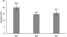
- FIG. 28 Elongation at break of LCP and FP blends according to certain embodiments.
- FIG. 29 The dimension change in the z direction for LCP and FP blends according to certain embodiments.
- FIG. 30 CTE of injection molded parts in the z-direction measured as the slope of the line of best fit for data in the 10-100° C and 100-200° C temperature ranges for LCP and FP blends according to certain embodiments.
- FIG. 31 Dielectric constant measured at 16 GHz using the split cavity method for LCP and FP blends according to certain embodiments.
- FIG. 32 Dielectric loss factor measured at 16 GHz using the split cavity method for LCP and FP blends according to certain embodiments.
- FIG. 33 Tensile strength for certain embodiments.
- FIG. 34 Tensile modulus of certain embodiments.
- FIG. 35 Elongation at break of certain embodiments.
- FIG. 36 Flexural modulus for certain embodiments.
- FIG. 37 Dielectric constant measured at 16 GHz using the split cavity method for certain embodiments.
- FIG. 38 Dielectric loss factor measured at 16 GHz using the split cavity method certain embodiments.
- first”, “second”, and the like are used herein to describe various features or elements, but these features or elements should not be limited by these terms. These terms are only used to distinguish one feature or element from another feature or element. Thus, a first feature or element discussed below could be termed a second feature or element, and similarly, a second feature or element discussed below could be termed a first feature or element without departing from the teachings of the present disclosure.
- any given elements of the disclosed embodiments of the invention may be embodied in a single structure, a single step, a single substance, or the like.
- a given element of the disclosed embodiment may be embodied in multiple structures, steps, substances, or the like.
- a copolymer is described that aids in creating blends of FP and LCP.
- This copolymer is referred to as a reactive polymer compatibilizer (RPC).
- RPC reactive polymer compatibilizer
- the RPC contains at least two types of monomers. In some embodiments, these monomers come from different types of molecules: fluorinated molecules and non-fluorinated monomers.
- RPCs can be made by mixing a functionalized fluoropolymer and a non-fluorinated monomer in an extruder.
- the functional group aids in polymerization of the RPC copolymer.
- the functional group is a moiety having an oxygen and/or a nitrogen.
- Examples of functional groups that are useful to encourage polymerization include carboxyl, hydroxyl, epoxy, amine, carboxyl ester, ester, and COF.
- the functionalized fluoropolymer contains a number of functionalized monomers.
- a given functionalized monomer may have two or more functional groups, which may be of the same kind or different from one another.
- a monomer may contain two carboxyl moieties.
- a fluorine-containing monomer may contain a carboxyl and a hydroxyl, a carboxyl and an epoxy, a carboxyl and an amine, a carboxyl and a carboxyl ester, a carboxyl and an ester, and a carboxyl and a COF.
- a fluorine-containing monomer may contain a hydroxyl and an epoxy, a hydroxyl and an amine, a hydroxyl and a carboxyl ester, a hydroxyl and an ester, and a hydroxyl and a COF.
- a fluorine-containing monomer may contain an epoxy and an amine, an epoxy and a carboxyl ester, an epoxy and an ester, and an epoxy and a COF.
- a fluorine-containing monomer may contain an amine and a carboxyl ester, an amine and an ester, and an amine and a COF.
- a fluorine-containing monomer may contain a carboxyl ester and an ester, and a carboxyl ester and a COF.
- a fluorine-containing monomer may contain an ester and a COF.
- a fluorine-containing monomer has two functional groups. Further embodiments of the fluorine-containing monomer may have 1-6 functional groups. Specific embodiments of the fluorine-containing monomer have 1, 2, 3, 4, 5, or 6 functional groups.
- the fluorine-containing molecule is fully fluorinated (i.e., composed of fluorine and carbon) except for the functional group or groups.
- a fluorine-containing monomer are composed of carbons saturated with fluorine except for the functional group; in other embodiments, one or more double or triple bonds may be present.
- fluoropolymer molecules include fluorinated ethylene propylene (FEP), functionalized FEP, perfluoroalkoxy alkane (PFA), functionalized PFA, tetrafluoroethylene-perfluoroalkyl vinyl ether copolymer, functionalized tetrafluoroethylene-perfluoroalkyl vinyl ether copolymer, ethylene tetrafluoroethylene (ETFE), functionalized ETFE, polychlorotrifluoroethylene (PCTFE), and functionalized PCTFE.
- FEP fluorinated ethylene propylene
- PFA perfluoroalkoxy alkane
- PFA perfluoroalkoxy alkane
- PFA perfluoroalkoxy alkane
- PFA perfluoroalkoxy alkane
- PFA perfluoroalkoxy alkane
- PFA perfluoroalkoxy alkane
- PFA perfluoroalkoxy alkane
- PFA perfluoro
- the non-fluorinated monomer is a monomer of a liquid crystal polymer.
- the monomer of the liquid crystal polymer may be any monomer of any liquid crystal polymer known in the art, or an aromatic compound having at least two functional groups.
- the aromatic compound may be a monoaromatic compound or a polyaromatic compound.
- Specific embodiments of the non-fluorinated monomer are a monoaromatic or diaromatic compound. The following are non-limiting examples of suitable liquid crystal monomers.
- the monomer is a monomer of a specific LCP, such as polyparaphenylene terephthalamide (KEVLAR).
- the RPC copolymer may contain one or both of the monomers 1,4-phenylene-diamine (para-phenylenediamine) and terephthaloyl chloride.
- Alternative embodiments of the copolymer may contain monomers of the aromatic polyester LCP VECTRAN, which has the following structure: where x and y are at least 1.
- the RPC copolymer may contain one or both of the monomers 4-hydroxybenzoic acid and 6-hydroxynaphthalene-2-carboxylic acid.
- the foregoing non-fluorinated monomers may be present in any combinations.
- the RPC copolymer may contain multiple species non-fluorinated or LCP monomers. Various embodiments of the copolymer may contain 1-12 species of non-fluorinated or LCP monomers. Specific embodiments of the RPC copolymer contain one species of non-fluorinated monomer or two species of fluorinated monomer. In some embodiments, the RPC copolymer contains the same species of liquid crystal monomer as the LCP in the LCP/FP blend.
- the RPC copolymer contains three types of molecules: a fluorinated molecule, a non-fluorinated monomer, and a linking molecule.
- the linking molecule is chosen for its molecular flexibility. This linking molecule may contain aliphatic chains or ether functional groups to provide molecular flexibility. In a some embodiments, the linking molecule is sourced from a polymeric rubber. In some embodiments, the linking molecule contains reactive functional groups, such as amine, carboxylic acid, ester, or anhydride. In some embodiments, the linking molecule contains at least 2 reactive functional groups.
- the non-fluorinated monomers may be chosen from the LCP monomer species discussed herein.
- the RPC copolymer contains only non-fluorinated moieties.
- one of these classes of monomer is the LCP monomers discussed previously.
- a molecule containing molecularly flexible linking moieties may be used.
- a non-fluorinated monomer has been functionalized to add reactive functional groups, such as, for example, amine, anhydride, carboxylic acid, or hydroxyl to the polymer.
- functional groups on the non-fluorinated polymer are chosen such that they can react in a facile way with any functional groups present on the flexible linking molecule.
- a fluorine-containing molecule will be present at a certain weight:weight ratio compared to the non-fluorinated molecule. For example, when the fluorine-containing molecule is present at the same mass concentration as the non-fluorinated molecule, the ratio of the fluorine-containing molecule to the non-fluorinated molecule is 1:1. Some embodiments of the copolymer have a ratio of the fluorine-containing molecule to the non-fluorinated molecule of 1:10 to 10:1.
- RPC copolymer has the said ratio of 1:10-3:1, 1:10-1:1, 1:10-1:3, 1:3-1:1, 1:3-3:1, 1:3-10:1, 1:1-3:1, 1:1-10:1, or 3:1-10:1.
- Specific embodiments of the RPC copolymer have a ratio of the fluorine-containing molecule to the non-fluorinated molecule selected from 1:10, 1:3, 1:1, 3:1, and 10:1.
- the “fluorine-containing molecule” can refer to multiple species of fluorine-containing molecule that together constitute a fluorine-containing molecule fraction of the copolymer.
- non-fluorinated molecule can refer to multiple species of non-fluorinated molecule that together constitute a non-fluorinated molecule fraction of the copolymer.
- a compatibilizer composition is described, useful for compatibilizing LCP and FP.
- the composition comprises the RPC copolymer described above.
- the compatibilizer composition is a compatibilizer blend, including a certain amount of a fluoropolymer.
- the fluoropolymer may be chosen based on the identity of the fluoropolymer in the ultimate FP/LCP blend (described in more detail below).
- the fluoropolymer is the same compound as the fluoropolymer in the ultimate FP/LCP blend.
- the fluoropolymer in the compatibilizer blend may be partially fluorinated or fully fluorinated; in a preferred embodiment, it is fully fluorinated.
- the fluoropolymer in the compatibilizer blend has no functional groups, to prevent participation in polymerization reactions during formation of the RPC copolymer.
- “functional groups” refers to the same moieties as described above regarding the fluorinated molecules of the RPC copolymer.
- suitable nonfunctionalized fluoropolymers in the compatibilizer blend are FEP, PFA, ETFE, PTFE, PVF, PVDF, PCTFE, ECTFE, FFPM/FFKM, FPM/FKM, FEPM, PFPE, PFSA, and combinations of two or more of the foregoing.
- the non-functionalized fluoropolymer is FEP.
- the non-functionalized fluoropolymer is PFA.
- a small molecules compatibilizer may be added to the compatibilizer composition, although in some embodiments of the LCP/FP blend a small molecule compatibilizer will be added to the blend after the compatibilizer composition has been prepared.
- Various small molecule compatibilizers may be used, including but not limited to a bis(oxazoline) compound, a carbonyl diimidazole compound, and an epoxy compound.
- the small molecule compatibilizer is 1,1’-carbonyl diimidazole.
- the small molecule compatibilizer is 1,3-phenylene-bis-oxazoline.
- Other suitable small molecule compatibilizers are shown below:
- the small molecule compatibilizer may be present at various concentrations. Measured as the mass percentage of the monomers, fluoropolymer, RPC compatibilizer, and small molecule compatibilizer, the small molecule compatibilizer may be present in the FP/LCP blend at 0.01-5.0%, 0.02-4.5%, 0.03-4.0%, 0.05-3.5%, 0.07-3.0%, 0.1-2.5%, 0.3-2.0%, 0.5-1.5%, 0.8-1.2%, and 1%.
- the compatibilizer composition can be prepared by various approaches.
- a method for producing the compatibilizer composition comprising: making a RPC copolymer by mixing a fully fluorinated fluoropolymer with a fluorinated molecule with reactive groups and a liquid crystal monomer, and making the compatibilizer composition by mixing the copolymer in an extruder. Polymerization of the fluorinated monomer with the liquid crystal monomer occurs during extrusion in such a process.
- Some embodiments of the RPC copolymer are suitable to be stored for later use, although in some embodiments of the process, the RPC copolymer blend is added to a mixture of an LCP and a FP shortly after it is produced.
- the RPC copolymer may contain one or more functionalized fluorinated monomers and one or more LCP monomers. These may be any monomers or molecules that are described above as suitable for incorporation into the LCP/FP RPC. In some embodiments, such monomers or molecules may also be present in relative amounts as described above in the RPC copolymer.
- RPC copolymer and compatibilizers described are useful in a compatibilized blend of an LCP and an FP.
- Many of the polymer blends thus produced have good mechanical properties (similar to pure LCP) combined with good chemical resistance (similar to pure FP).
- Various FP may be used in the blend, including but not limited to FEP, PFA, ETFE, PTFE, PVF, PVDF, PCTFE, ECTFE, FFPM/FFKM, FPM/FKM, FEPM, PFPE, PFSA, and combinations of two or more of the foregoing.
- the FP is FEP.
- the FP is PFA.
- LCP may be used in the blend, including polyparaphenylene terephthalamide (KEVLAR) and LCP VECTRAN.
- Further suitable LCPs may be polymers of 6-hydroxy-2-naphthoic acid, 4-hydroxybenzoic acid, aminobenzoic acid, aminophenol, terephthalic acid, and isoterephthalic acid.
- Further suitable LCPs may be copolymers of one or more of 6-hydroxy-2-naphthoic acid, 4-hydroxybenzoic acid, aminobenzoic acid, aminophenol, terephthalic acid, and isoterephthalic acid.
- Either of the LCP or FP may be independently selected from a random copolymer, a homopolymer, a block copolymer, an alternating copolymer, and a graft copolymer.
- the LCP is a copolymer of 6-hydroxy-2-naphthoic acid and 4-hydroxybenzoic acid.
- Suitable properties have been obtained using various relative proportions of FP to LCP, as illustrated in the examples below.
- Some embodiments of the polymer blend have a ratio of the FP to LCP of no more than 25:75 w/w. Further embodiments of the polymer blend have a ratio of FP:LCP no more than 20:80 w/w. Further embodiments of the polymer blend have a ratio of FP:LCP no more than 15:85 w/w. Further embodiments of the polymer blend have a ratio of FP:LCP no more than 10:90 w/w. Still further embodiments of the polymer blend have a ratio of FP:LCP no more than 5:95 w/w.
- Still further embodiments of the polymer blend have a ratio of FP:LCP of 1:20-1:4. Still further embodiments of the polymer blend have a ratio of FP:LCP of 1:10-1:5. Still further embodiments of the polymer blend have a ratio of FP:LCP of 1:10-1:5. Some embodiments of the polymer blend have a ratio of the FP to LCP of no more than 75:25 w/w. Further embodiments of the polymer blend have a ratio of FP:LCP no more than 80:20 w/w. Further embodiments of the polymer blend have a ratio of FP:LCP no more than 85:15 w/w.
- polymer blends have a ratio of FP:LCP no more than 90:10 w/w. Still further embodiments of the polymer blend have a ratio of FP:LCP no more than 5:95 w/w. Still further embodiments of the polymer blend have a ratio of FP:LCP of 20:1-4:1. Still further embodiments of the polymer blend have a ratio of FP:LCP of 10:1-5:1.
- the polymer blend may contain any of the RPC copolymers described above; in some embodiments of the polymer blend, the RPC copolymer is part of a compatibilizer composition.
- the compatibilizer composition may be any described above.
- the compatibilizer may be present in an amount effective to compatibilize the LCP with the FP in the polymer blend.
- the compatibilizer may be present at up to 30% w/w of the polymer blend.
- the compatibilizer may be present at up to 20% w/w of the polymer blend.
- the compatibilizer may be present at up to 15% w/w of the polymer blend.
- the compatibilizer may be present at 1-30% w/w of the polymer blend.
- the compatibilizer may be present at 2.5-25% w/w of the polymer blend.
- the compatibilizer may be present at 5-15% w/w of the polymer blend.
- the polymer blend may show various physical characteristics, as partially illustrated in the examples below. Some embodiments of the polymer blend show continuous phase and no fibrillation morphology. Some preferred embodiments of the polymer blend have a high Young’s modulus. Embodiments of the polymer blend may have a Young’s modulus of at least 220, 400, 500, 600, 700, or 900 MPa. Preferred embodiments of the polymer blend have a Young’s modulus above that of a pure composition of one or more of the fluoropolymers in the polymer blend. A specific preferred embodiment of the polymer blend has a Young’s modulus at least 200% that of a pure composition of one or more of the fluoropolymers in the polymer blend.
- Embodiments of the polymer blend have shown good maximum tensile strength, as partially illustrated in the examples below.
- Embodiments of the polymer blend may have tensile strengths of at least 20, 30, 35, 38, or 40 MPa.
- the polymer blend has a maximum tensile strength above that of a pure composition of the fluoropolymer.
- Some embodiments of the polymer blend have shown high elongation (% elongation to failure). Some embodiments of the polymer blend have an elongation of at least 3%; further embodiments of the polymer blend have an elongation of at least 5%; further embodiments of the polymer blend have an elongation of at least 8%; further embodiments of the polymer blend have an elongation of at least 70%; further embodiments of the polymer blend have an elongation of at least 74%. In a preferred embodiment, the polymer blend has an elongation at least equal to that of a pure composition of the fluoropolymer.
- Some embodiments of the polymer blend have shown low coefficients of thermal expansion (CTE). Some embodiments of the polymer blend have a CTE at about 80° C of no more than 180, 100, 97, or 95 ppm/°C. In a preferred embodiment, the polymer blend has a CTE at 80° C below that of a pure composition of at least one of the fluoropolymers in the polymer blend. Some embodiments of the polymer blend have a CTE at about 100° C of no more than 200, 195, or 95 ppm/°C. In a preferred embodiment, the polymer blend has a CTE at about 100° C below that of a pure composition of at least one of the fluoropolymers in the polymer blend.
- CTE coefficients of thermal expansion
- the polymer blend have a CTE at 120° C of no more than about 200 or 150 ppm/°C. In a preferred embodiment, the polymer blend has a CTE at about 120° C below that of a pure composition of at least one of the fluoropolymers in the polymer blend. Some embodiments of the polymer blend have a CTE at 180° C of no more than 200 ppm/°C. In a preferred embodiment, the polymer blend has a CTE at about 180° C below that of a pure composition of at least one of the fluoropolymers in the polymer blend.
- the polymer blend has a coefficient of thermal expansion at 80, 100, 120, 150 and 180° C below that of a pure composition of at least one of the fluoropolymers in the polymer blend.
- the polymer blend has a Young’s modulus of at least 500 MPa, an elongation to failure of at least 70%, and a coefficient of thermal expansion at about 100° C of below 100 ppm/°C.
- Some embodiments of the polymer blend have displayed high temperatures at which 5% weight loss occurs. Some embodiments of the polymer blend have a temperature of 5% weight loss in N 2 above 480° C. A preferred embodiment of the polymer blend has a temperature of 5% weight loss in N 2 no more than that of a pure composition of at least one of the fluoropolymers in the blend.
- Embodiments of the polymer blend have shown low glass transition temperatures. Some embodiments of the polymer blend have a glass transition temperature below 100° C. A preferred embodiment of the polymer blend has a glass transition temperature that is the same as a pure composition of at least one of the fluoropolymers in the polymer blend.
- Embodiments of the polymer blend have shown good flexural load characteristics. Some embodiments of the polymer blend have a flexural stress at maximum flexure load that is about the same as a pure composition of at least one of the fluoropolymers in the blend. Further embodiments of the polymer blend have a flexural modulus above 600 MPa. Further embodiments of the polymer blend have a flexural modulus above 1,000 MPa. Further embodiments of the polymer blend have a flexural modulus at least 120% relative to at least one of the pure fluoropolymers in the blend. Still further embodiments of the polymer blend have a flexural modulus at least 200% relative to at least one of the pure fluoropolymers in the blend. Some embodiments of the polymer blend have a flexural modulus of at least 800%, at least 1,000%, at least 1,200%, or at least 1,400% relative to at least one of the pure fluoropolymers in the blend.
- Embodiments of the polymer blend have been observed to have dielectric properties particularly suitable for use in electronics applications. Some embodiments of the polymer blend have a dielectric constant at 10 GHz of 2-3; further embodiments of the polymer blend have a dielectric constant at 10 GHz of about 2.1. Embodiments of the polymer blend have been observed to have low dielectric loss factors as well. Some embodiments of the polymer blend may have a dielectric loss factor at 10 GHz below 0.0050. Further embodiments of the polymer blend may have a dielectric loss factor at 10 GHz of 0.0003-0.0050. Still further embodiments of the polymer blend may have a dielectric loss factor at 10 GHz of 0.0010.
- a preferred embodiment of the polymer blend has a dielectric loss factor at 10 GHz less than that of a pure composition of at least one of the LCP in the blend.
- a further preferred embodiment of the polymer blend has a dielectric loss factor at 10 GHz 20% that of a pure composition of at least one of the LCP in the blend.
- Articles of manufacture of many kinds can be made using various embodiments of the polymer blend.
- Such articles include an extruded fiber comprising the polymer blend.
- Embodiments of such extruded fibers may contain over 50% w/w, at least 75%, at least 80%, at least 85%, at least 90%, at least 95%, at least 96%, at least 97%, at least 98%, at least 99%, or 100% w/w of the polymer blend.
- the polymer also finds use in the form of thin films.
- Embodiments of such thin films may contain over 50% w/w, at least 75%, at least 80%, at least 85%, at least 90%, at least 95%, at least 96%, at least 97%, at least 98%, at least 99%, or 100% w/w of the polymer blend.
- Further articles of manufacture include an insulator for a communications cable, a printed circuit board, a tape, twisted pair high speed cable for automotive, thin film for high temperature capacitors and coating for down-hole oil & gas drilling, fibers for 3D printed article, single and multi-fiber for woven and non-woven substrates for filtration, proton exchange membrane and printed circuit boards, thin film substrate 1-1000 microns thick for printed circuit boards, wire & cable for down-hole cable, tape wrap for electrical insulation, inorganic fillers for tapes (aluminum hydroxide, ceramic glass, SiO 2 , fluorosilicate glass), thermal conductive additives, foam for wire & cable, an automobile comprising any of the foregoing, an electric vehicle comprising any of the foregoing, and an aircraft comprising any of the foregoing.
- Example 1 Preparation of FEP/LCP Reactive Polymer Compatibilizers
- a fully fluorinated FEP, a carboxylated FEP, 6-hydroxy-2-naphthoic acid, and 4-hydroxybenzoic acid were all added to one bag and mixed uniformly.
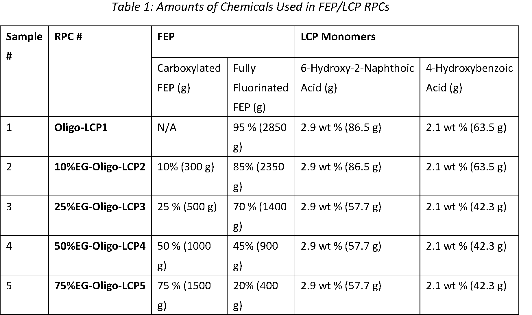
- the amounts of each chemical used in the RPC are shown in Table 1.
- the LCP monomers, 6-hydroxy-2-napthoic acid and 4-hydroxybenzoic acid, were both added at one-to-one molar equivalents and totaled 5 wt % of all formulations.
- the carboxylated FEP was varied in each sample from 10 to 75 wt % in samples 2 to 5, respectively.
- FIG. 1 shows an example of a scheme for producing the FEP/LCP RPC.
- the preparation of the FEP/LCP RPC occurs via polycondensation in the twin screw extruder.
- the step growth polycondensation is driven by the heat of the extruder and the HF produced by the fully fluorinated FEP and/or carboxylated FEP serves a Lewis acid driving the reaction.
- the aromatic monomers, 6-hydroxy-2-naphthic acid and 4-hydroxybenzoic acid, are effective in lowering the interfacial tension between the fully fluorinated FEP and LCP.
- both monomers can polymerize with another molecule of the sample molecular structure or other monomer.
- the corresponding random copolymers, monomers, and oligomers can only react with the end groups of the carboxylated FEP to produce AB or ABA type random block copolymers.
- sample 1 Oligo-LCP1
- sample 5 75%EG-Oligo-LCP5
- SEM scanning electron microscopy
- FIG. 2 is a SEM image of sample 1 (Oligo-LCP1) at 1500x magnification. The image of FIG. 2 shows the presence of fibril morphology.
- FIG. 3 is a SEM image of sample 5 (75%EG-Oligo-LCP5) at 2000x magnification. The image of FIG. 3 shows a continuous phase and no fibrillation morphology observed throughout the sample. This indicates that sample 5 (75%EG-Oligo-LCP5) is a continuous AB and ABA block copolymer.
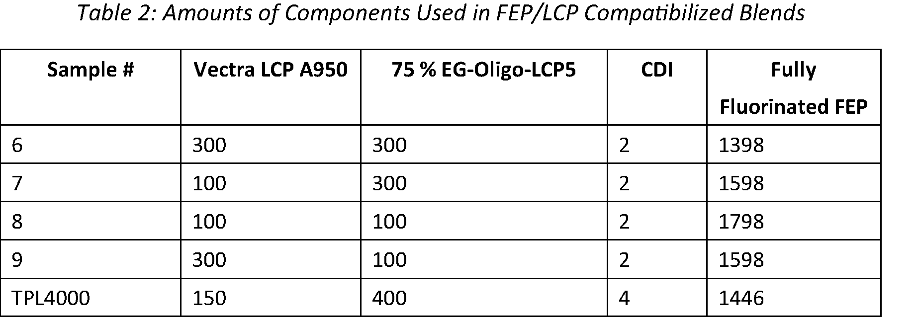
- Example 2 Preparation Of FEP/LCP Compatibilized Blends After the FEP/LCP RPCs were made, the block copolymers were blended in a twin screw extruder with Vectra LCP A950, 75%EG-Oligo-LCP5, fully fluorinated FEP, and 1,1’-Carbonyldiimidazole (CDI). The amounts of each component used in the various samples are shown in Table 2 below.
- the 75%EG-Oligo-LCP4 component served as a compatibilizer by lowering the interfacial tension between the Vectra LCP A950 and the fully fluorinated FEP and increasing the molecular adhesion between the Vectra LCP A950 and the fully fluorinated FEP to achieve a homogeneous blend.
- CDI was employed as a reactive compatibilizer in these formulations due to its ability to react with the alcohol end groups to create a new ester bond and the carboxylic acid end groups to create a new anhydride bond.
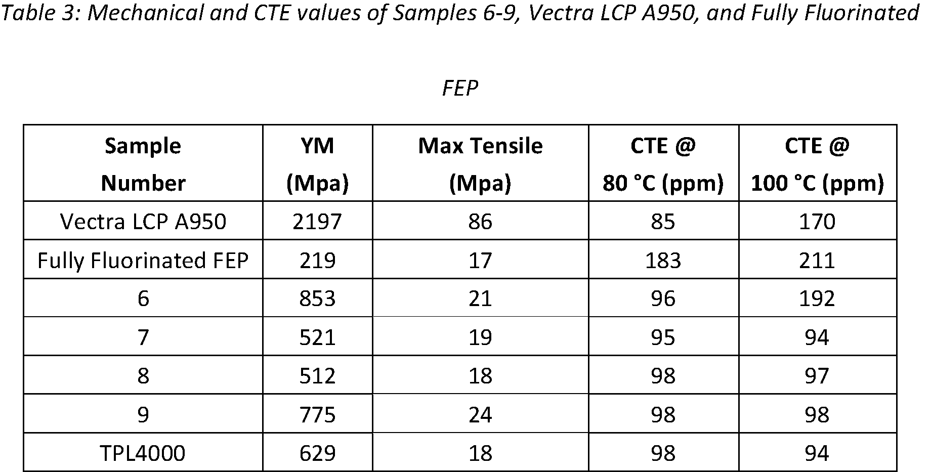
- Example 3 Mechanical and Thermal Properties of the FEP/LCP Compatibilized Blends Mechanical and thermal properties of samples 6-9 and TPL4000 (shown in Table 2 above) were tested and compared to fully fluorinated FEP and Vectra LCP A950. Samples were gravity fed into a Sumitomo SE75DU injection molding machine. The feed zone was kept at 49 °C. Zones 1 to 5 were heated from 304 °C to 327 °C. The filling time was 5.00 seconds while the fill pressure was 10.00 kpsi. The screw was pulled back 0.3 inches at a rate of 0.2 inches/second. The samples were molded into ASTM D638 Type V for tensile testing, ASTM D790 flexural bars for dynamic mechanical analysis (DMA), and 61 mm x 61 mm plaques for thermal mechanical analysis (TMA) testing.
- DMA dynamic mechanical analysis
- TMA thermal mechanical analysis
- Samples 7, 8, and TPL4000 also underwent testing to calculate flexural modulus, maximum flexure load, and flexure stress. All 3-point flexural tests were performed according to ASTM D790-03 using a calibrated Instron and injection molded ASTM D790 flexural bars. The samples were placed on top of two metal rollers 50 mm apart in the Instron. A rod was utilized to provide a load at a rate of 1.35 mm/min. An Instron computer program was used to calculate modulus, maximum flexure load, and flexure stress at maximum flexure load. The results of these tests are shown in Table 4 below. All data represent one flexural bar.
- CTE coefficient of thermal expansion
- sample 8 shows improvement at 80°C, 100°C, 120°C, 150°C, and 180°C.
- the 3-point bend test was employed to determine the compatibility of the LCP in the fully fluorinated FEP.
- a control was run without the addition of an RPC copolymer.
- the LCP control sample showed a maximum flexure load of 166 and a modulus of 1174 Mpa. When the control is compared to sample 7, the maximum flexure load and modulus of sample 7 are much lower than the control. These values indicate an increase in compatibility.
- Sample 8 has lower CTEs than sample 7 but maintains the flexibility of the fully fluorinated FEP.
- Example 4 Mechanical, Electrical, and Thermal Properties of Additional FEP/LCP Compatibilized Blends
- TPL4000 containing 7.5 wt % of Vectra LCP A950 was prepared according to the procedure described in Example 2.
- Mechanical, electrical, and thermal properties of the resulting FEP/LCP compatibilized blend (TPL4000) were tested and compared to FEP and LCP. The tensile, flexural, and CTE tests were performed using the procedures outlined in Example 3.
- CTE was measured by a TA Instruments TMA Q400 using 2.0 to 3.0 ⁇ m samples cut from injection molded 61 mm x 61 mm plaques. Initial sample dimensions were measured using a Mitutoyo series 293 micrometer. All samples were run using the following method: 1: Force 0.100 N. 2: Equilibrate at 45.00° C. 3: Mark end of cycle 0. 4: Ramp 10.00°C/min to 100.00°C. 5: Isothermal for 5.00 min. 6: Mark end of cycle 1. 7: Ramp 10.00°C/min to 55.00° C. 8: Mark end of cycle 2. 9: Ramp 5.00°C/min to 190.00° C. 10: Mark end of cycle 3. 11: Jump to 30.00° C. 12: End of method.
- CTE, ⁇ was calculated using the following equation: where L 0 represents the initial sample height at 25 °C, ⁇ L represents the change in length in microns ( ⁇ m), and ⁇ T represents the change in temperature in degrees Celsius (°C). All samples were measured at change ( ⁇ T) of 5 degrees Celsius.
- the results of the CTE testing are shown in Table 4 above. All values reported are perpendicular, Z direction, to the flow direction of the injection molded sample.
- FIG. 4 is a graph showing the tensile modulus of the FEP/LCP compatibilized blend compared to FEP and LCP. As shown in FIG. 4, the FEP/LCP compatibilized blend shows approximately a threefold increase in tensile modulus when compared to FEP.
- FIG. 5 is a graph showing the CTE of FEP, LCP, and the FEP/LCP compatibilized blend at 100°C.
- the CTE of the FEP/LCP compatibilized blend is lower than both unblended polymers (i.e., the FEP and the LCP).
- the CTE of the FEP/LCP compatibilized blend is nearly two times lower than the CTE of the FEP and the LCP.
- FIG. 6 is a graph showing the thermal stability as measured by loss in nitrogen of the FEP, LCP, and the FEP/LCP compatibilized blend.
- the y-axis is the temperature at which 5% weight loss was observed.
- the FEP/LCP compatibilized blend demonstrates only a slight decrease in weight loss when compared to the FEP.
- FIG. 7 is a graph showing the glass transition temperatures of FEP, LCP, and the FEP/LCP compatibilized blend. As can be seen in FIG. 7, the glass transition temperature of the FEP/LCP compatibilized blend is similar to that of the FEP.
- FIG. 8 and 9 show the results of flexural testing.
- FIG. 8 is a graph showing the flexural stress at maximum flexure load of FEP, LCP, and the FEP/LCP compatibilized blend. As shown in FIG. 8, the maximum flexure load of the FEP/LCP compatibilized blend is lower than for the unblended LCP.
- FIG. 9 is a graph showing the flexural modulus of FEP, LCP, and the FEP/LCP compatibilized blend. The flexural modulus of the FEP/LCP compatibilized blend is lower than for the unblended LCP.
- Example 5 Mechanical and Thermal Properties of Additional FEP/LCP Compatibilized Blends
- Two FEP/LCP compatibilized blends were prepared according to the procedure described in Example 2.
- the FEP/LCP compatibilized blends TG1000 and TG2000 were prepared containing 7.5 wt % and 15.0 wt % of Vectra LCP A950, respectively.
- Mechanical and thermal properties of the resulting FEP/LCP compatibilized blends were tested and compared to FEP. The tensile, flexural, and CTE tests were performed using the procedures outlined in Example 3.
- FIG. 10 and 11 show the results of the mechanical tensile tests.
- FIG. 10 is a graph showing the maximum tensile strength of thin films made from each of the FEP/LCP compatibilized blends as compared to FEP alone.
- the second FEP/LCP compatibilized blend shows an increase in maximum tensile strength when compared to FEP alone.
- FIG. 11 is a graph showing the Young’s modulus of thin films made from each of the FEP/LCP compatibilized blends as compared to FEP alone. As can be seen in FIG. 11, the FEP/LCP compatibilized blends have Young’s modulus values about three times that of the FEP alone.
- FIG. 12 and 13 show the results of the flexural tests.
- FIG. 12 is a graph showing the maximum flexure load of thin films made from each of the FEP/LCP compatibilized blends as compared to FEP alone.
- the first FEP/LCP compatibilized blend (TG1000) had a maximum flexure load nearly the same as FEP.
- FIG. 13 is a graph showing the flexural modulus of thin films made from each of the FEP/LCP compatibilized blends as compared to FEP alone.
- the second FEP/LCP compatibilized blend (TG2000) had the highest flexural modulus, which is between two and three times that of the flexural modulus for FEP.
- FIG. 14 shows the results of the CTE testing.
- FIG. 14 is a graph showing the CTE of thin films made from each of the FEP/LCP compatibilized blends as compared to FEP alone at five temperatures: 80°C, 100°C, 120°C, 150°C, and 180°C.
- the first FEP/LCP compatibilized blend (TG1000) has a lower CTE than FEP at all temperatures.
- the second FEP/LCP compatibilized blend (TG2000) has a lower CTE than FEP at all temperatures except 180°C.
- Example 6 Preparation of PFA/LCP Fibers
- a reactive polymer compatibilizer was made by blending a sheared perfluoroalkoxy alkane (PFA) with a hydroxyl-1-napthoic acid monomer, a hydroxybenzoic acid monomer, and a liquid crystalline polymer (LCP). The percentage of each chemical is shown in Table 5 below. Once the samples were thoroughly mixed, the mixture was fed at 4.0 - 6.0 kg/hr into a Leist ⁇ ritz ZSE-18 HP-PH twin screw extruder and extruded into a pellet form. Zones 1 through 8 were heated from 340°C to 360°C for sample 220E. The screw was kept at a constant of 250 RPM. The compatibilizer blend pellets blend were slight grey in color.
- PFA sheared perfluoroalkoxy alkane
- LCP liquid crystalline polymer
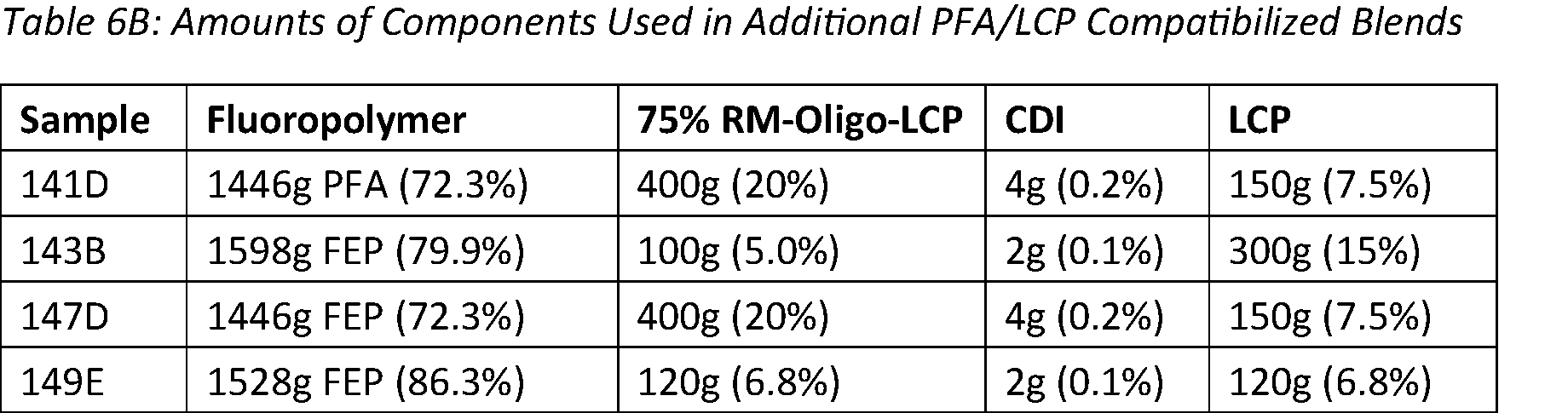
- Blend formulations for the compatibilization with PFA and LCP are shown in Tables 6A and B below.
- the reactive polymer compatibilizer made above (sample 220E), PFA, LCP, 1,1'-carbonyldiimidazole, and silocym-A nanoparticles were added to one bag and mixed until homogeneous. As shown in Table 6, the nanoparticles were not utilized in sample 220F.
- the mixture was fed at 4.0- 6.0 kg/hr into a Leistritz ZSE-18 HP-PH twin screw extruder and the compound was extruded into pellet form. Zones 1 through 8 were heated from 340°C to 360°C and the screw speed was held constant at 250 RPM.
- PFA/LCP blends were obtained as grey pellets.
- the PFA/LCP fibers were produced on a Leistriz ZSE 27 HP twin screw extruder equipped with a 12-hole block die with a 0.7mm hole diameter.
- the screw speed was kept constant at 100 rpms and the feed rate was held constant at 3.0 kg/hr.
- the melt pressure was between 325 to 500 PSI.
- Temperatures from zone 1 to 12 were between 325 °C to 350 °C.
- the fibers were air cooled with a pickup rate of 100ft/min.
- the resulting fibers had diameters measuring from 0.09 mm to 0.2 mm.
- Example 7 Mechanical Properties of PFA/LCP Fibers Individual fibers were attached to paper mounts following ASTM D-3379-75 with a gauge length of 30 mm using Staples Glue Tape Permanent. A secondary line of Staples Glue Tape Permanent and a piece of paper were used to secure the fibers in place and to eliminate direct friction onto the fibers from the Instron grips. For each sample, the diameter of the fiber was measured using a Ziess SteREO Discovery V.12 microscope. The mechanical properties of the fluoropolymer and fluoropolymer alloy fibers were measured using an Instron 5582 Universal Tester. The Instron was equipped with 1kN load cells and wedge action grips.
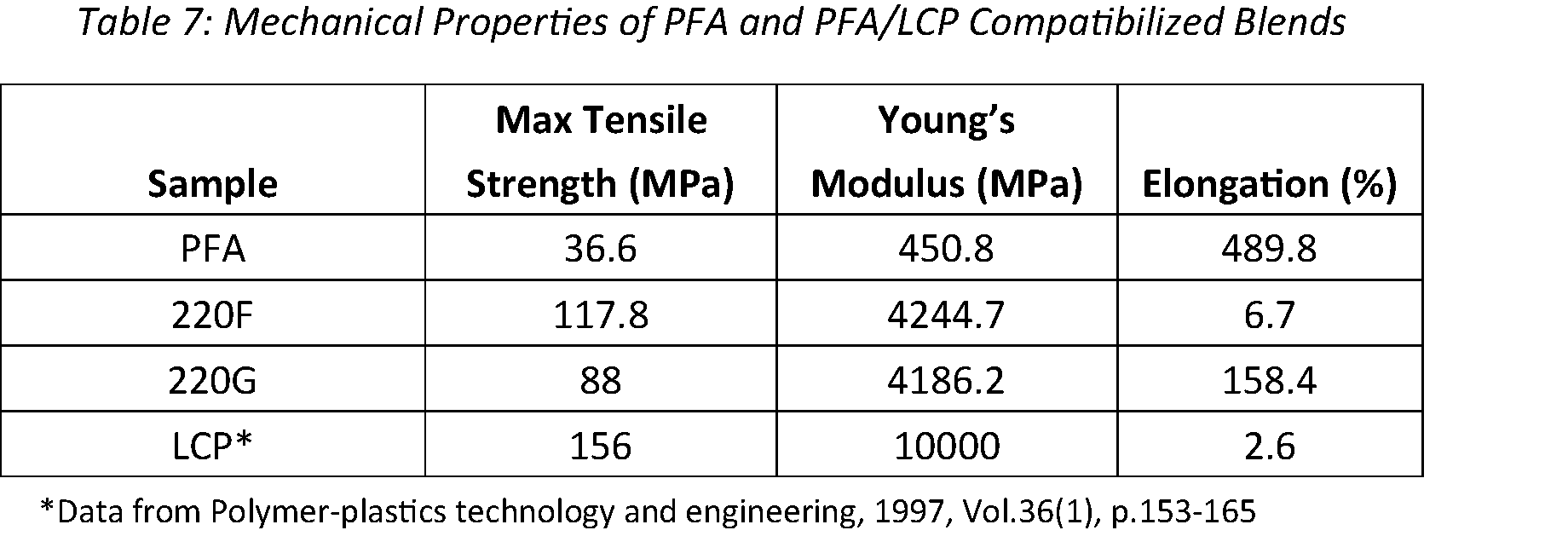
- Table 7 displays the mechanical properties of the fibers produced from pure PFA and the PFA/LCP compatibilized blends (shown in Table 6A) at room temperature.
- Table 7 shows the addition of 7.5 weight % of LCP dramatically increased the tensile strength and tensile modulus.
- the tensile strength of Sample 220F was 3.2 times higher than that of the PFA, while the Young’s Modulus was 9.4 times higher than that of the PFA.
- the elongation of the PFA/LCP blends decreased compared to pure PFA. This is believed to be due to the highly crystalline nature of LCP decreasing the elasticity of blends.
- the small addition of nanoparticles within Sample 220G disrupted the crystalline areas of the LCP polymer within the blend allowing for an increase in elongation compared to Sample 220F which contains no nanoparticles.
- Example 8 Electrical Properties of PFA/LCP Compatibilized Blends
- Samples of pure PFA, Samples 220F and 220G (the formulations of which are described in Table 6A), 141D, 143B, 147D, and 149E (the formulations of which are described in Table 6B).
- a sample thickness was measured at four to five locations using a digital caliper and averaged.
- the samples were then inserted into the cavity. Measurements were made using Keysight P9374A PNA sand NIST SplitC software. In samples having defects, the best area was used to cover the cavity opening.
- Table 8 shows the electrical properties of each sample. More specifically, Table 8 shows the dielectric constant and the dielectric loss factor at 17 GHz of pure PFA and the PFA/LCP compatibilized blends (Samples 220F and 220G). As shown in Table 8, the dielectric constant of the PFA/LCP compatibilized blends is higher than the dielectric constant of the pure PFA. The dielectric loss factor of the PFA/LCP compatibilized blends is also higher than the pure PFA.
- Example 9 Preparation of Additional PFA/LCP Compatibilized Blends
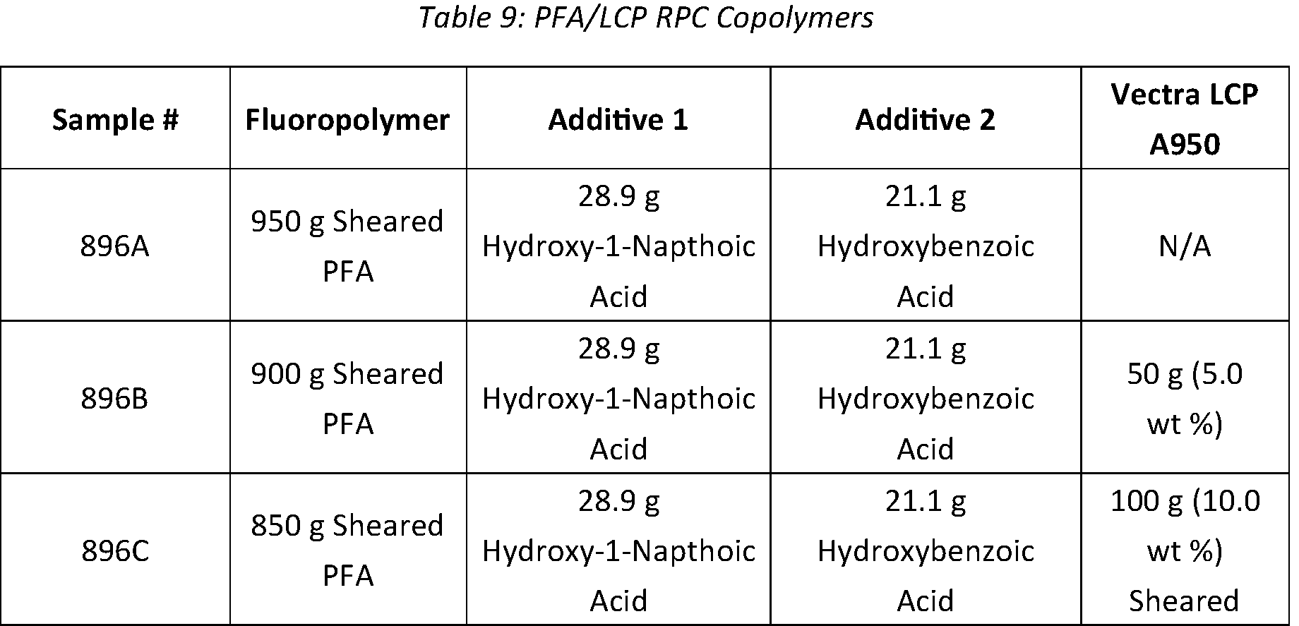
- PFA/LCP RPC copolymers were prepared. Sheared PFA, Vectra LCP A950, 6-hydroxy-2-naphthoic acid, and 4-hydroxybenzoic acid were all added to one bag and mixed uniformly. Amounts of each chemical are shown in Table 9 below. 6-hydroxy-2-napthoic acid and 4-hydroxybenzoic acid, LCP monomers, were both added at one-to-one molar equivalents and totaled 5 weight % of all formulations. Once the samples were thoroughly mixed, the mixture was fed at 4.0 to 6.0 Kg/hr into a Leistritz ZSE 18 HP.
- Zones 1 through 8 were heated from 310°C to 340°C for each sample.
- the screw speed was kept constant at 250 rpm.
- the PFA/LCP RPC copolymers may also be prepared with or without the presence of PFA. All RPC copolymers were obtained as brown pellets.
- FIG. 15 shows an example of a scheme for producing the PFA/LCP RPC copolymers.
- the preparation of the PFA/LCP RPC copolymer occurs via polycondensation in the twin-screw extruder.
- the step growth polycondensation is driven by the heat of the extruder.
- the HF produced by the PFA and/or the sheared PFA serves as a Lewis acid driving the reaction.
- Aromatic monomers, 6-Hydroxy-2-Naphthic acid and 4-Hydroxybenzoic acid are common LCP monomers and are effective in lowering the interfacial tension between PFA and LCP.
- 6-Hydroxy-2-Naphthoic acid and 4-Hydroxybenzoic acid being A-B type functional monomers, they both have the ability to polymerize with another molecule of the sample molecular structure or another monomer.
- the corresponding random copolymers, monomers, and oligomers can react with the end groups of the sheared PFA and Vectra LCP A950 to produce a random block copolymer.
- Example 10 Mechanical Properties of PFA/LCP Compatibilized Blends
- the samples from Example 9 were gravity fed into a Sumitomo SE75DU injection molder. The feed zone was kept at 49 °C. Zones 1 through 5, in the rotating screw, were heated from 310°C to 340°C. Filling time was 5.00 seconds while fill pressure was 10.00 kpsi. The screw was pulled back 0.3 in at a rate of 0.2 in/second. Samples were molded into ASTM D638 Type V for tensile testing, ASTM D790 flexural bars for dynamic mechanical analysis (DMA), and 61 mm x 61 mm plaques for thermal mechanical analysis (TMA) testing.
- DMA dynamic mechanical analysis
- TMA thermal mechanical analysis
- TMA thermal mechanical analysis
- CTE coefficient of thermal expansion
- Table 11 shows the tensile properties of the PFA/LCP compatibilized blends.
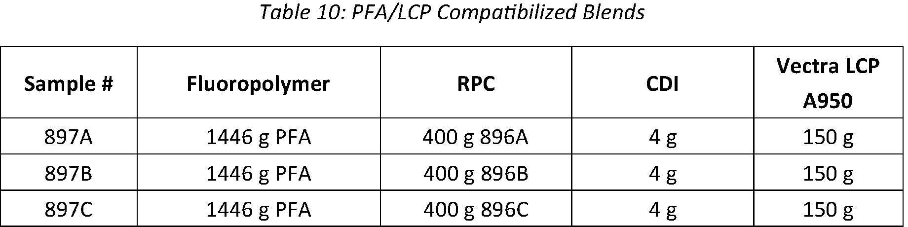
- the formulations of each of Samples 897A-C are shown in Table 10 above. As shown in Table 11 below, Sample 897A displayed the highest max tensile with a value of 21 MPa. While Sample 897B had the highest Young’s Modulus (YM) of 826 MPa, the sample demonstrated a slight improvement in elongation compared to the PFA/LCP formulation of Sample 897C. All formulations demonstrated an increase in YM when compared to pure PFA. Samples 897A and 897B showed a slight improvement in max tensile when compared to pure PFA.
- YM Young’s Modulus
- Table 12 below shows the coefficient of thermal expansion (CTE) values of Samples 897A-C, pure PFA, and LCP Vectra A950.
- CTE values were higher for Samples 897A and 897B at 80°C and 100°C compared to Sample 897C, pure PFA, and LCP Vectra A950. While the CTE values for Sample 897C were 138 ppm/°C and 141 ppm/°C at 100°C and 120°C, respectively, the CTE values increased at the higher temperatures (150°C and 180°C). At 180 °C, Sample 897B had a CTE value of 117 ppm/°C, which is lower than the CTE value of LCP Vectra A950 at 180 °C.
- Tables 13 and 14 below show the storage modulus and the glass transition temperatures, respectively, of PFA and the PFA/LCP compatibilized blends. As demonstrated in Table 13, the PFA/LCP compatibilized blends exhibited higher storage modulus values than the pure PFA. Additionally, as can be seen in Table 14, the glass transition temperatures of the PFA/LCP compatibilized blends were lower than the pure PFA.
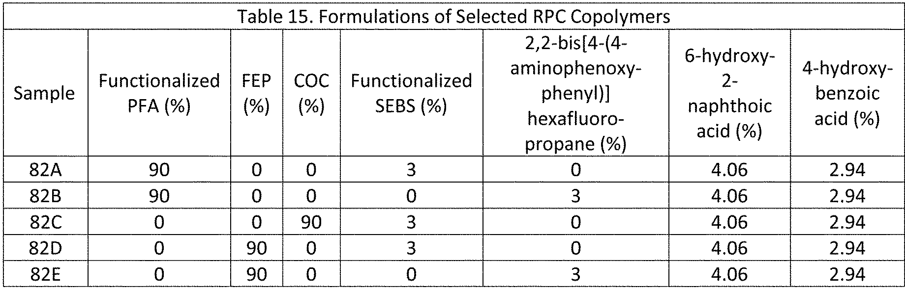
- Example 11 Additional Compatibilizer Formulations
- all reactive polymer compatibilizers utilized fluorinated polymers and non-fluorinated monomers.
- monomers or polymers can be added to provide molecular flexibility to the RPC copolymer.
- These linking molecules include flexible moieties such as aliphatic chains or ether functional groups.
- These linking molecules may also contain a reactive functional group such as amine.
- the linking molecules is used to chemically link the LCP monomers to the polymeric backbone. This allows the molecularly rigid polymerized LCP units, called mesogens, the flexibility to align with one another, thereby providing mechanical strength as well as localized domains that may be compatible with LCP polymers.
- fluorine-free RPC copolymers may also be used to compatibilize LCP/FP blends.
- a non-fluorinated polymer is combined with non-fluorinated monomers.
- a fluorine-free linking molecule may be used.
- the non-fluorinated polymer contains reactive functional groups such as carboxylic acid, hydroxyl, ester, and anhydride; and the non-fluorinated monomers are preferably chosen from LCP monomers such as 6-hydroxy-2-naphthoic acid and 4-hydroxybenzoic acid.
- Non-limiting examples of non-fluorinated polymers suitable for this purpose include the copolymers of cyclic olefins (COCs) shown in Figure 16.
- each polymer contains a reactive functional group, such as, for example, carboxylic acid, hydroxyl, ester, COF, or anhydride. This functional group may be present as an end group, that is, only at the end of the polymer chain, or be present throughout the polymer chain.
- the linking molecules include a SEBS (styrene-ethylene-butadiene-styrene) thermoplastic elastomeric rubber functionalized with amine reactive groups and 2,2-bis[4-(4-aminophenoxyphenyl)] hexafluoropropane.
- LCP monomers 6-hydroxy-2-naphthoic acid and 4-hydroixybenzoic acid are used in a 1:1 molar ratio.
- the components were mixed together and fed into a co-rotating twin screw extruder with the temperature profiles shown in Table 16. Zone 1 is near the feeder, while zone 8 is the die. Materials were fed into the extruder at 5.5 kg/hr and the extruder motor rotated at 300 RPM. The extrudate was cooled in a water bath and pelletized.
- Example 12 Use of Compatibilizer to Blend LCP and Fluoropolymer
- the RPC copolymers described in Example 11 can be used to compatibilize blends of liquid crystalline polymers and fluoropolymers.
- linking molecules such as functionalized SEBS rubber, can be added to the LCP / FP blends.
- another molecule is used in addition to the RPC copolymer to improve the compatibility between the LCP and fluoropolymer.
- this molecule is 1,3-bis(4,5-dihydro-2-oxazolyl) benzene, but molecules with a variety of functional groups are also effective.
- Table 17 shows the composition of some exemplary LCP / FP blends. In these blends, the fluoropolymer may or may not have a reactive functional group.
- Sample 90A showed the most enhanced properties. As already mentioned, 90A has superior mechanical properties to 92E and has lower CTE at 10-100° C than sample 92A. Additionally, SEM micrographs were taken of selected samples. These are shown in Figures 23-25. From these micrographs, it is apparent that the presence of RPC 82A improves the compatibility of LCP / FP blends. The microstructures of 92C and 92D show much larger texture than that of 90A. This indicates that in sample 90A, the surface tension between LCP and PFA is lower, allowing for smaller LCP and PFA domains. The lowered surface tension may be a result of the RPC. Additionally, as seen in Figure 21, the absence of the RPC results in higher dielectric constant. The use of a small molecule compatibilizer alone, as exhibited in sample 92C, does not appear to lower the surface tension between the PFA and LCP.
- Example 13 Use of various reactive polymer compatibilizers in LCP / Fluoropolymer Blends.
- reactive polymer compatibilizers can be useful for effective blending of LCP and fluoropolymers, each of the reactive polymer compatibilizers discussed in Example 11 were used to create exemplary fluoropolymer / LCP blends.
- Table 19 shows the composition of some blends of LCP and fluoropolymer compatibilized using the RPCs discussed in Example 11.
- sample 85A had the highest tensile strength as well as the highest elongation at break.
- sample 88A had the lowest tensile strength and the lowest elongation a break, while 88B and 88C performed similarly to each other.
- Samples 85C and 88A had significant shrinkage above 100° C, suggesting that the presence of 82C reactive polymer compatibilizer causes shrinkage at higher temperatures.
- the CTE at 100-200° C for each of these embodiments is lower than that of the corresponding fluoropolymer alone. Despite this, the CTE in the z direction is still relatively high.
- sample 85A has the lowest Dk and Df of the PFA-based samples. All the FEP-based samples showed lower dielectric loss constants than the PFA-based samples.
- Example 14 Ratio of LCP to Fluoropolymer
- RPCs that may compatibilize LCP and fluoropolymers. However, in example 13, only one ratio of fluoropolymer to LCP was studied.
- the RPCs are capable of compatibilizing a wide range of LCP/fluoropolymer compositions.
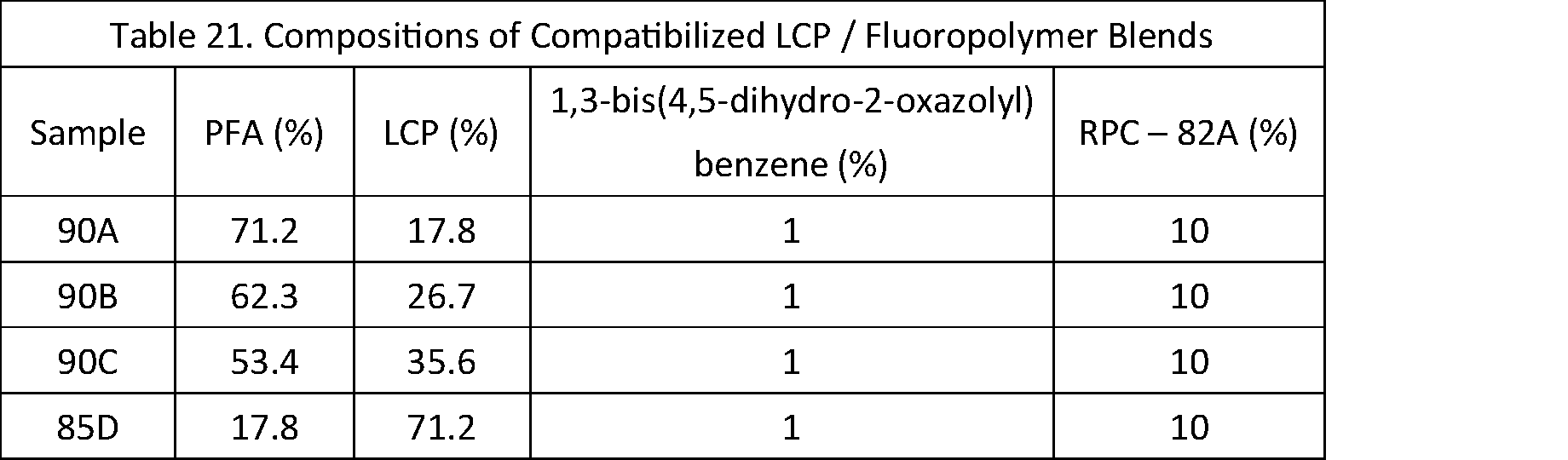
- the compositions of samples in this example 14 are shown in Table 21. Note that sample 90A has the same composition and processing conditions as sample 85A, however, the samples were processed at different times.
- the samples in this example 14 were each mixed together and fed into a twin screw extruder at 5.5 kg/hr; the extruder was run at 300 RPM. The temperatures used were those listed in Table 20 for samples 85A-C.
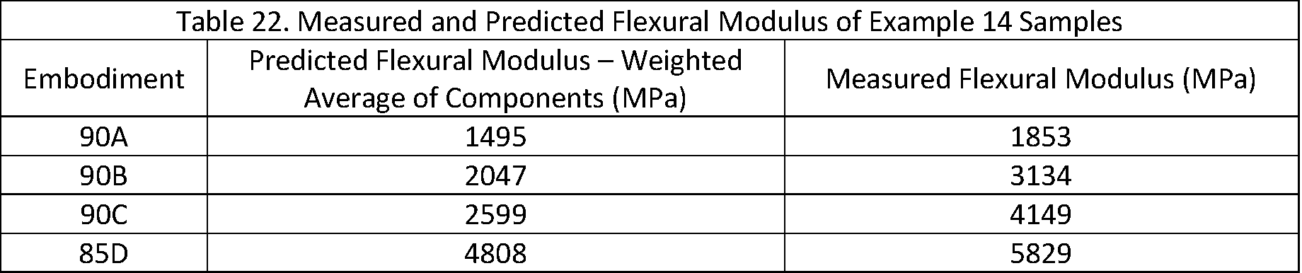
- the flexural modulus of PFA has previously been measured as 399 MPa. Taking this and the measured flexural modulus of LCP as 6602, we can predict what the flexural modulus of LCP / PFA blends would be if the flexural modulus was proportional to the weighted average of only LCP and PFA components.
- the predicted flexural modulus for these embodiments is shown in Table 22. Note that the PFA amount used in this calculation includes the PFA in the reactive polymer compatibilizer, however, the other compatibilizing components (total of 2 wt% of the blends) are not included in this calculation.
- the dielectric properties of these embodiments were measured using the split cavity method at 16 GHz.
- the dielectric constant and dielectric loss factor for these embodiments are shown in Figures 37 and 38, respectively.
- a trend is observed where the higher the LCP content of a sample, the higher the Df of that sample. Therefore, the most desired sample is dependent upon the application for which it will be used. For flexible applications, sample 90A may be desired, while for applications where mechanical strength is needed, sample 85D may be more desirable.
- Embodiments of the disclosed method of blending these polymers includes the synthesis and/or use of a reactive polymer compatibilizer and, in some embodiments, a small molecule compatibilizer.
- Embodiments of the reactive polymer compatibilizers are created by combining at least one polymer with at least one class of monomer.
- one of the polymers is a fluoropolymer that may be a functionalized fluoropolymer containing reactive groups.
- this polymer may also be a non-fluorinated polymer such as a cyclic olefin copolymer.
- non-fluorinated monomers are LCP monomers.
- a linking molecule may be added to enhance the molecular flexibility of the reactive polymer compatibilizer and allow the constructed LCP mesogens to align in a facile manner.
- any given elements of the disclosed embodiments of the invention may be embodied in a single structure, a single step, a single substance, or the like.
- a given element of the disclosed embodiment may be embodied in multiple structures, steps, substances, or the like.
Landscapes
- Chemical & Material Sciences (AREA)
- Organic Chemistry (AREA)
- Health & Medical Sciences (AREA)
- Chemical Kinetics & Catalysis (AREA)
- Medicinal Chemistry (AREA)
- Polymers & Plastics (AREA)
- Crystallography & Structural Chemistry (AREA)
- Engineering & Computer Science (AREA)
- Materials Engineering (AREA)
- Compositions Of Macromolecular Compounds (AREA)
Abstract
Description


To form the FEP/LCP RPCs described in this example 1, a fully fluorinated FEP, a carboxylated FEP, 6-hydroxy-2-naphthoic acid, and 4-hydroxybenzoic acid were all added to one bag and mixed uniformly. The amounts of each chemical used in the RPC are shown in Table 1. The LCP monomers, 6-hydroxy-2-napthoic acid and 4-hydroxybenzoic acid, were both added at one-to-one molar equivalents and totaled 5 wt % of all formulations. The carboxylated FEP was varied in each sample from 10 to 75 wt % in
After the FEP/LCP RPCs were made, the block copolymers were blended in a twin screw extruder with Vectra LCP A950, 75%EG-Oligo-LCP5, fully fluorinated FEP, and 1,1’-Carbonyldiimidazole (CDI). The amounts of each component used in the various samples are shown in Table 2 below.
Mechanical and thermal properties of samples 6-9 and TPL4000 (shown in Table 2 above) were tested and compared to fully fluorinated FEP and Vectra LCP A950. Samples were gravity fed into a Sumitomo SE75DU injection molding machine. The feed zone was kept at 49 °
1: Force 0.100 N
2: Equilibrate at 45.00°C
3: Mark end of
4: Ramp 10.00°C/min to 100.00°C
5: Isothermal for 5.00 min
6: Mark end of
7: Ramp 10.00°C/min to 55.00°C
8: Mark end of
9: Ramp 5.00°C/min to 190.00°C
10: Mark end of cycle 3
11: Jump to 30.00°C
12: End of method.
CTE, α, was calculated using the following equation:


A FEP/LCP compatibilized blend, TPL4000, containing 7.5 wt % of Vectra LCP A950 was prepared according to the procedure described in Example 2. Mechanical, electrical, and thermal properties of the resulting FEP/LCP compatibilized blend (TPL4000) were tested and compared to FEP and LCP. The tensile, flexural, and CTE tests were performed using the procedures outlined in Example 3.
1: Force 0.100 N.
2: Equilibrate at 45.00° C.
3: Mark end of
4: Ramp 10.00°C/min to 100.00°C.
5: Isothermal for 5.00 min.
6: Mark end of
7: Ramp 10.00°C/min to 55.00° C.
8: Mark end of
9: Ramp 5.00°C/min to 190.00° C.
10: Mark end of cycle 3.
11: Jump to 30.00° C.
12: End of method.
CTE, α, was calculated using the following equation:

Step 1: Equilibrate at 45° C.
Step 2: Ramp 10° C/min to 800° C.
From the results the 1% weight loss temperature and 5% weight loss temperature were calculated.
FIG. 4 is a graph showing the tensile modulus of the FEP/LCP compatibilized blend compared to FEP and LCP. As shown in FIG. 4, the FEP/LCP compatibilized blend shows approximately a threefold increase in tensile modulus when compared to FEP.
Two FEP/LCP compatibilized blends were prepared according to the procedure described in Example 2. The FEP/LCP compatibilized blends TG1000 and TG2000 were prepared containing 7.5 wt % and 15.0 wt % of Vectra LCP A950, respectively. Mechanical and thermal properties of the resulting FEP/LCP compatibilized blends were tested and compared to FEP. The tensile, flexural, and CTE tests were performed using the procedures outlined in Example 3.
A reactive polymer compatibilizer was made by blending a sheared perfluoroalkoxy alkane (PFA) with a hydroxyl-1-napthoic acid monomer, a hydroxybenzoic acid monomer, and a liquid crystalline polymer (LCP). The percentage of each chemical is shown in Table 5 below. Once the samples were thoroughly mixed, the mixture was fed at 4.0 - 6.0 kg/hr into a Leistμritz ZSE-18 HP-PH twin screw extruder and extruded into a pellet form.


Individual fibers were attached to paper mounts following ASTM D-3379-75 with a gauge length of 30 mm using Staples Glue Tape Permanent. A secondary line of Staples Glue Tape Permanent and a piece of paper were used to secure the fibers in place and to eliminate direct friction onto the fibers from the Instron grips. For each sample, the diameter of the fiber was measured using a Ziess SteREO Discovery V.12 microscope. The mechanical properties of the fluoropolymer and fluoropolymer alloy fibers were measured using an Instron 5582 Universal Tester. The Instron was equipped with 1kN load cells and wedge action grips. Once each sample was loaded into the wedge action grips, the fiber mounts were cut using scissors. Tensile measurements were carried out with an extension rate of 50 mm/min until break. Using the
The electrical properties of the following samples were tested in this example: Samples of pure PFA, Samples 220F and 220G (the formulations of which are described in Table 6A), 141D, 143B, 147D, and 149E (the formulations of which are described in Table 6B). For each sample, a sample thickness was measured at four to five locations using a digital caliper and averaged. The samples were then inserted into the cavity. Measurements were made using Keysight P9374A PNA sand NIST SplitC software. In samples having defects, the best area was used to cover the cavity opening.

PFA/LCP RPC copolymers were prepared. Sheared PFA, Vectra LCP A950, 6-hydroxy-2-naphthoic acid, and 4-hydroxybenzoic acid were all added to one bag and mixed uniformly. Amounts of each chemical are shown in Table 9 below. 6-hydroxy-2-napthoic acid and 4-hydroxybenzoic acid, LCP monomers, were both added at one-to-one molar equivalents and totaled 5 weight % of all formulations. Once the samples were thoroughly mixed, the mixture was fed at 4.0 to 6.0 Kg/hr into a
The samples from Example 9 were gravity fed into a Sumitomo SE75DU injection molder. The feed zone was kept at 49 °
1: Force 0.100 N
2: Equilibrate at 45.00°C
3: Mark end of
4: Ramp 10.00°C/min to 100.00°C
5: Isothermal for 5.00 min
6: Mark end of
7: Ramp 10.00°C/min to 55.00°C
8: Mark end of
9: Ramp 5.00°C/min to 190.00°C
10: Mark end of cycle 3
11: Jump to 30.00°C
12: End of method.
The CTE, α, was calculated using the following equation:


In the previous examples 1-10, all reactive polymer compatibilizers utilized fluorinated polymers and non-fluorinated monomers. In addition to these categories of materials, monomers or polymers can be added to provide molecular flexibility to the RPC copolymer. These linking molecules include flexible moieties such as aliphatic chains or ether functional groups. These linking molecules may also contain a reactive functional group such as amine. The linking molecules is used to chemically link the LCP monomers to the polymeric backbone. This allows the molecularly rigid polymerized LCP units, called mesogens, the flexibility to align with one another, thereby providing mechanical strength as well as localized domains that may be compatible with LCP polymers.

The RPC copolymers described in Example 11 can be used to compatibilize blends of liquid crystalline polymers and fluoropolymers. Additionally, linking molecules, such as functionalized SEBS rubber, can be added to the LCP / FP blends. In some embodiments, another molecule is used in addition to the RPC copolymer to improve the compatibility between the LCP and fluoropolymer. In some embodiments, this molecule is 1,3-bis(4,5-dihydro-2-oxazolyl) benzene, but molecules with a variety of functional groups are also effective. Table 17 shows the composition of some exemplary LCP / FP blends. In these blends, the fluoropolymer may or may not have a reactive functional group.


As reactive polymer compatibilizers can be useful for effective blending of LCP and fluoropolymers, each of the reactive polymer compatibilizers discussed in Example 11 were used to create exemplary fluoropolymer / LCP blends. Table 19 shows the composition of some blends of LCP and fluoropolymer compatibilized using the RPCs discussed in Example 11.


In example 13, it is shown that there are many RPCs that may compatibilize LCP and fluoropolymers. However, in example 13, only one ratio of fluoropolymer to LCP was studied. The RPCs are capable of compatibilizing a wide range of LCP/fluoropolymer compositions. The compositions of samples in this example 14 are shown in Table 21. Note that
Claims (20)
- A polymer blend comprising a fluoropolymer, a liquid crystal polymer, and a compatibilizer composition, wherein the compatibilizer composition comprises a copolymer having a fluorine-containing molecule and a liquid crystal monomer.
- The polymer blend of claim 1, wherein the compatibilizer composition further comprises a small molecule compatibilizer.
- The polymer blend of claim 1, wherein the compatibilizer composition further comprises a linking molecule.
- The polymer blend of claim 3, wherein the linking molecule is a styrene-ethylene-butadiene-styrene rubber.
- The polymer blend of claim 3, wherein the linking molecule is bound to both the fluorine-containing molecule and the liquid crystal monomer.
- The polymer blend of claim 1, wherein the compatibilizer composition further comprises a fully fluorinated fluoropolymer selected from: fluorinated ethylene propylene (FEP) or perfluoroalkoxy alkane (PFA).
- The polymer blend of claim 1, wherein the polymer blend comprises at least 15% w/w liquid crystal polymer.
- The polymer blend of claim 1, wherein the fluoropolymer is fluorinated ethylene propylene (FEP).
- The polymer blend of claim 1, wherein the fluoropolymer is perfluoroalkoxy alkane (PFA).
- The polymer blend of claim 9, wherein the polymer blend comprises at least 65% w/w PFA and at least 15% w/w liquid crystal polymer.
- The polymer blend of claim 9, wherein the polymer blend comprises between about 68% and 72% w/w PFA, between about 17% and 20% w/w liquid crystal polymer, and between about 8% and 12% w/w compatibilizer composition.
- The polymer blend of claim 1, wherein the liquid crystal polymer is the same species as the liquid crystal monomer of the compatibilizer composition.
- The polymer blend of claim 1, wherein the polymer blend has a flexural modulus of at least 800% of the flexural modulus of the fluoropolymer alone.
- A polymer blend comprising a fluoropolymer, a liquid crystal polymer, and a compatibilizer composition, wherein the compatibilizer composition comprises a copolymer having a perfluoroalkoxy alkane (PFA) molecule and at least two different liquid crystal monomers.
- The polymer blend of claim 14, wherein the liquid crystal monomers comprise 6-hydroxy-2-naphthoic acid and 4-hydroxy-benzoic acid.
- The polymer blend of claim 14, wherein the compatibilizer composition further comprises a styrene-ethylene-butadiene-styrene thermoplastic elastomeric rubber.
- The polymer blend of claim 14, wherein the polymer blend has a maximum tensile strength greater than a pure composition of PFA.
- The polymer blend of claim 14, wherein the polymer blend has a lower coefficient of thermal expansion at 100-200° C than a pure composition of PFA.
- The polymer blend of claim 14, wherein the polymer blend has a % elongation to failure at least 15%.
- A polymer blend comprising a fluoropolymer, a liquid crystal polymer, and reactive polymer compatibilizer copolymer, wherein the reactive polymer compatibilizer copolymer is created from the reaction of a functionalized fluoropolymer, a linking molecule, and at least one LCP monomer.
Priority Applications (5)
| Application Number | Priority Date | Filing Date | Title |
|---|---|---|---|
| EP21864430.0A EP4208508A4 (en) | 2020-09-04 | 2021-09-03 | MIXTURE COMPRISING A FLUOROPOLYMER AND A LIQUID CRYSTAL POLYMER |
| CN202180053531.5A CN116057105A (en) | 2020-09-04 | 2021-09-03 | Fluoropolymer and Liquid Crystal Polymer Blends |
| JP2023514755A JP7623474B2 (en) | 2020-09-04 | 2021-09-03 | Fluoropolymer and Liquid Crystal Polymer Blends |
| KR1020237009166A KR20230053659A (en) | 2020-09-04 | 2021-09-03 | Blends of fluoropolymers and liquid crystal polymers |
| US18/177,828 US12351752B2 (en) | 2020-09-04 | 2023-03-03 | Fluoropolymer and liquid crystal polymer blend |
Applications Claiming Priority (2)
| Application Number | Priority Date | Filing Date | Title |
|---|---|---|---|
| US202063074631P | 2020-09-04 | 2020-09-04 | |
| US63/074,631 | 2020-09-04 |
Related Child Applications (1)
| Application Number | Title | Priority Date | Filing Date |
|---|---|---|---|
| US18/177,828 Continuation US12351752B2 (en) | 2020-09-04 | 2023-03-03 | Fluoropolymer and liquid crystal polymer blend |
Publications (1)
| Publication Number | Publication Date |
|---|---|
| WO2022050378A1 true WO2022050378A1 (en) | 2022-03-10 |
Family
ID=80491038
Family Applications (1)
| Application Number | Title | Priority Date | Filing Date |
|---|---|---|---|
| PCT/JP2021/032446 Ceased WO2022050378A1 (en) | 2020-09-04 | 2021-09-03 | Fluoropolymer and liquid crystal polymer blend |
Country Status (7)
| Country | Link |
|---|---|
| US (1) | US12351752B2 (en) |
| EP (1) | EP4208508A4 (en) |
| JP (1) | JP7623474B2 (en) |
| KR (1) | KR20230053659A (en) |
| CN (1) | CN116057105A (en) |
| TW (1) | TWI908873B (en) |
| WO (1) | WO2022050378A1 (en) |
Cited By (3)
| Publication number | Priority date | Publication date | Assignee | Title |
|---|---|---|---|---|
| WO2025019824A1 (en) * | 2023-07-20 | 2025-01-23 | Axoft, Inc. | Perfluoropolyether copolymers for biomedical applications |
| US12351752B2 (en) | 2020-09-04 | 2025-07-08 | Daikin America, Inc. | Fluoropolymer and liquid crystal polymer blend |
| US12428551B2 (en) | 2019-08-30 | 2025-09-30 | Daikin America, Inc. | Chemically compatibilized fluoropolymer blends |
Families Citing this family (1)
| Publication number | Priority date | Publication date | Assignee | Title |
|---|---|---|---|---|
| JP2025154041A (en) * | 2024-03-29 | 2025-10-10 | ダイキン工業株式会社 | Resin composition, molded body, and compatibilizer |
Citations (7)
| Publication number | Priority date | Publication date | Assignee | Title |
|---|---|---|---|---|
| WO1994014890A1 (en) | 1992-12-21 | 1994-07-07 | Raychem Corporation | Polymeric blends |
| US5767198A (en) * | 1994-04-28 | 1998-06-16 | Daikin Industries, Ltd. | Thermoplastic resin composition |
| US20010006727A1 (en) * | 1999-12-24 | 2001-07-05 | Lee Jeong C. | Melt processible fluoropolymer composites |
| US20050197460A1 (en) | 2004-03-04 | 2005-09-08 | Raman Patel | Compatibilizers for fluoropolymers and polyolefins; blends thereof |
| US20070200274A1 (en) | 2001-10-24 | 2007-08-30 | Lee Jeong C | Fluoropolymer laminates and a process for manufacture thereof |
| US20180015647A1 (en) | 2016-07-18 | 2018-01-18 | Equistar Chemicals, Lp | Polyolefin compatibilizer composition for compounding to improve stiffness and impact balance |
| WO2020226034A1 (en) * | 2019-05-08 | 2020-11-12 | 三菱エンジニアリングプラスチックス株式会社 | Polycarbonate resin composition |
Family Cites Families (18)
| Publication number | Priority date | Publication date | Assignee | Title |
|---|---|---|---|---|
| KR100320251B1 (en) | 1994-06-09 | 2002-01-12 | 이노우에 노리유끼 | Fluorine-containing olefin |
| JPH09309961A (en) | 1996-05-23 | 1997-12-02 | Toray Ind Inc | Polyester film and manufacturing method thereof |
| JPH11209548A (en) | 1998-01-20 | 1999-08-03 | Asahi Glass Co Ltd | Fluorine-containing resin composition |
| US6797781B2 (en) | 2002-04-26 | 2004-09-28 | Teknor Apex Company | Blends of fluoropolymer and plasticized polyvinyl chloride |
| US7625974B2 (en) * | 2005-09-30 | 2009-12-01 | Alphagary Corporation | Highly filled unsaturated fluoropolymer compositions for cables |
| WO2008127767A2 (en) | 2007-04-12 | 2008-10-23 | Ppg Industries Ohio, Inc. | Curable film-forming compositions demonstrating burnish resistance and low gloss |
| JP5684477B2 (en) | 2010-01-05 | 2015-03-11 | ダイキン工業株式会社 | Gelling agent for fluorine-containing organic solvent, and compatibilizing agent for fluorine-containing organic solvent and fluorine-free organic solvent |
| JP2014130215A (en) | 2012-12-28 | 2014-07-10 | Ricoh Co Ltd | Seamless belt, manufacturing method thereof, and image forming apparatus |
| CN104530719A (en) | 2014-12-29 | 2015-04-22 | 中国兵器工业集团第五三研究所 | Vinyl blocked poly(trifluoropropyl)methylsiloxane fluororubber compatibilizer and preparation method thereof |
| JP2018536119A (en) | 2015-09-25 | 2018-12-06 | サン−ゴバン パフォーマンス プラスティックス コーポレイション | Adhesive, bearing having adhesive, and manufacturing method |
| EP3387054B1 (en) | 2015-12-07 | 2020-02-26 | E. I. du Pont de Nemours and Company | Curing agents for fluorinated elastomers |
| US20170226389A1 (en) | 2016-02-10 | 2017-08-10 | Tyco Electronics Corporation | Adhesive Arrangement |
| CN105838160B (en) | 2016-04-08 | 2017-06-27 | 晔重新材料科技(上海)有限公司 | Coating composition and its lubricating and wear-resisting polytetrafluoroethylene (PTFE) rubber coating of preparation |
| US11692090B2 (en) | 2019-08-01 | 2023-07-04 | Daikin America, Inc. | Dielectric cross-linked fluoropolymer |
| EP3986962A4 (en) | 2019-08-30 | 2023-07-19 | Daikin America, Inc. | Chemically compatibilized fluoropolymer blends |
| CN110511533B (en) | 2019-09-06 | 2020-08-04 | 吉林大学 | Polyetheretherketone/tetrafluoroethylene-perfluoroalkoxyvinylether copolymer/chopped quartz fiber material, preparation method and application |
| JP7543548B2 (en) | 2020-09-04 | 2024-09-02 | ダイキン アメリカ インコーポレイティッド | Reactive fluoropolymer compatibilizers and uses thereof |
| EP4208508A4 (en) | 2020-09-04 | 2024-10-09 | Daikin America, Inc. | MIXTURE COMPRISING A FLUOROPOLYMER AND A LIQUID CRYSTAL POLYMER |
-
2021
- 2021-09-03 EP EP21864430.0A patent/EP4208508A4/en active Pending
- 2021-09-03 KR KR1020237009166A patent/KR20230053659A/en not_active Ceased
- 2021-09-03 WO PCT/JP2021/032446 patent/WO2022050378A1/en not_active Ceased
- 2021-09-03 CN CN202180053531.5A patent/CN116057105A/en active Pending
- 2021-09-03 JP JP2023514755A patent/JP7623474B2/en active Active
- 2021-09-03 TW TW110132928A patent/TWI908873B/en active
-
2023
- 2023-03-03 US US18/177,828 patent/US12351752B2/en active Active
Patent Citations (7)
| Publication number | Priority date | Publication date | Assignee | Title |
|---|---|---|---|---|
| WO1994014890A1 (en) | 1992-12-21 | 1994-07-07 | Raychem Corporation | Polymeric blends |
| US5767198A (en) * | 1994-04-28 | 1998-06-16 | Daikin Industries, Ltd. | Thermoplastic resin composition |
| US20010006727A1 (en) * | 1999-12-24 | 2001-07-05 | Lee Jeong C. | Melt processible fluoropolymer composites |
| US20070200274A1 (en) | 2001-10-24 | 2007-08-30 | Lee Jeong C | Fluoropolymer laminates and a process for manufacture thereof |
| US20050197460A1 (en) | 2004-03-04 | 2005-09-08 | Raman Patel | Compatibilizers for fluoropolymers and polyolefins; blends thereof |
| US20180015647A1 (en) | 2016-07-18 | 2018-01-18 | Equistar Chemicals, Lp | Polyolefin compatibilizer composition for compounding to improve stiffness and impact balance |
| WO2020226034A1 (en) * | 2019-05-08 | 2020-11-12 | 三菱エンジニアリングプラスチックス株式会社 | Polycarbonate resin composition |
Non-Patent Citations (1)
| Title |
|---|
| See also references of EP4208508A4 |
Cited By (3)
| Publication number | Priority date | Publication date | Assignee | Title |
|---|---|---|---|---|
| US12428551B2 (en) | 2019-08-30 | 2025-09-30 | Daikin America, Inc. | Chemically compatibilized fluoropolymer blends |
| US12351752B2 (en) | 2020-09-04 | 2025-07-08 | Daikin America, Inc. | Fluoropolymer and liquid crystal polymer blend |
| WO2025019824A1 (en) * | 2023-07-20 | 2025-01-23 | Axoft, Inc. | Perfluoropolyether copolymers for biomedical applications |
Also Published As
| Publication number | Publication date |
|---|---|
| TW202216844A (en) | 2022-05-01 |
| KR20230053659A (en) | 2023-04-21 |
| EP4208508A4 (en) | 2024-10-09 |
| EP4208508A1 (en) | 2023-07-12 |
| CN116057105A (en) | 2023-05-02 |
| TWI908873B (en) | 2025-12-21 |
| JP7623474B2 (en) | 2025-01-28 |
| US20230203375A1 (en) | 2023-06-29 |
| US12351752B2 (en) | 2025-07-08 |
| JP2023540108A (en) | 2023-09-21 |
Similar Documents
| Publication | Publication Date | Title |
|---|---|---|
| US12351752B2 (en) | Fluoropolymer and liquid crystal polymer blend | |
| US20230203292A1 (en) | Reactive fluoropolymer compatibilizer and uses thereof | |
| JP3700178B2 (en) | Thermoplastic resin composition | |
| JP7312767B2 (en) | Resin composition and resin molded article made from the resin composition | |
| EP2881430B1 (en) | Resin composition and molded article | |
| EP2418249A2 (en) | Wholly aromatic liquid crystalline polyester resin compound with improved flowability, and method for preparing same | |
| KR102919129B1 (en) | Resin composition and resin molded product comprising the resin composition | |
| JPH0558453B2 (en) | ||
| Lee et al. | Amphiphilic block co-polymer and silica reinforced epoxy composite with excellent toughness and delamination resistance for durable electronic packaging application | |
| US20240327561A1 (en) | Fluoropolymer and cyclic olefin alloy | |
| JP2023500518A (en) | Blends of polyaryletherketone copolymers | |
| US20230383076A1 (en) | Polymer film and laminate | |
| WO2022202790A1 (en) | Polymer film and layered body | |
| JP4265328B2 (en) | Polyarylene sulfide resin composition and molded article using the same | |
| KR100561095B1 (en) | Multilayer insulated wire | |
| TWI402860B (en) | Cable insulation compositions with enhanced rheology and processability | |
| De Melo et al. | Rheology–Performance Framework for PA6/GO Nanocomposites via a Hybrid Processing Route | |
| JP2002294053A (en) | Thermoplastic polyester resin composition | |
| KR20240116384A (en) | Reactive extrusion composition and PLA/P(3HP) blend manufactured from thereof | |
| WO2006037755A1 (en) | Sulfone polymer composition | |
| JPH05179132A (en) | Polymer composition and its preparation |
Legal Events
| Date | Code | Title | Description |
|---|---|---|---|
| 121 | Ep: the epo has been informed by wipo that ep was designated in this application |
Ref document number: 21864430 Country of ref document: EP Kind code of ref document: A1 |
|
| ENP | Entry into the national phase |
Ref document number: 2023514755 Country of ref document: JP Kind code of ref document: A |
|
| ENP | Entry into the national phase |
Ref document number: 20237009166 Country of ref document: KR Kind code of ref document: A |
|
| NENP | Non-entry into the national phase |
Ref country code: DE |
|
| ENP | Entry into the national phase |
Ref document number: 2021864430 Country of ref document: EP Effective date: 20230404 |
|
| WWR | Wipo information: refused in national office |
Ref document number: 1020237009166 Country of ref document: KR |
|
| WWC | Wipo information: continuation of processing after refusal or withdrawal |
Ref document number: 1020237009166 Country of ref document: KR |