WO2022054214A1 - 鉗子装置 - Google Patents
鉗子装置 Download PDFInfo
- Publication number
- WO2022054214A1 WO2022054214A1 PCT/JP2020/034370 JP2020034370W WO2022054214A1 WO 2022054214 A1 WO2022054214 A1 WO 2022054214A1 JP 2020034370 W JP2020034370 W JP 2020034370W WO 2022054214 A1 WO2022054214 A1 WO 2022054214A1
- Authority
- WO
- WIPO (PCT)
- Prior art keywords
- pulley
- grip
- grip portion
- guide
- support
- Prior art date
- Legal status (The legal status is an assumption and is not a legal conclusion. Google has not performed a legal analysis and makes no representation as to the accuracy of the status listed.)
- Ceased
Links
Images






Classifications
-
- A—HUMAN NECESSITIES
- A61—MEDICAL OR VETERINARY SCIENCE; HYGIENE
- A61B—DIAGNOSIS; SURGERY; IDENTIFICATION
- A61B17/00—Surgical instruments, devices or methods
- A61B17/28—Surgical forceps
- A61B17/29—Forceps for use in minimally invasive surgery
-
- A—HUMAN NECESSITIES
- A61—MEDICAL OR VETERINARY SCIENCE; HYGIENE
- A61B—DIAGNOSIS; SURGERY; IDENTIFICATION
- A61B34/00—Computer-aided surgery; Manipulators or robots specially adapted for use in surgery
- A61B34/70—Manipulators specially adapted for use in surgery
- A61B34/71—Manipulators operated by drive cable mechanisms
-
- A—HUMAN NECESSITIES
- A61—MEDICAL OR VETERINARY SCIENCE; HYGIENE
- A61B—DIAGNOSIS; SURGERY; IDENTIFICATION
- A61B34/00—Computer-aided surgery; Manipulators or robots specially adapted for use in surgery
- A61B34/30—Surgical robots
-
- A—HUMAN NECESSITIES
- A61—MEDICAL OR VETERINARY SCIENCE; HYGIENE
- A61B—DIAGNOSIS; SURGERY; IDENTIFICATION
- A61B17/00—Surgical instruments, devices or methods
- A61B17/28—Surgical forceps
- A61B17/29—Forceps for use in minimally invasive surgery
- A61B2017/2901—Details of shaft
- A61B2017/2902—Details of shaft characterized by features of the actuating rod
- A61B2017/2903—Details of shaft characterized by features of the actuating rod transferring rotary motion
-
- A—HUMAN NECESSITIES
- A61—MEDICAL OR VETERINARY SCIENCE; HYGIENE
- A61B—DIAGNOSIS; SURGERY; IDENTIFICATION
- A61B34/00—Computer-aided surgery; Manipulators or robots specially adapted for use in surgery
- A61B34/30—Surgical robots
- A61B2034/305—Details of wrist mechanisms at distal ends of robotic arms
Definitions
- the present invention relates to a forceps device used in a manipulator of a surgical robot.
- Patent Document 1 Various surgical tools are attached to the tip of the surgical manipulator, and forceps that grip the tissues of the human body during surgery are known as surgical tools.
- two discs having different outer diameters are provided for each of the two jaw portions serving as grip portions, and forceps for opening and closing the jaw portions by pulling a wire hanging on each disc are provided. It has been disclosed.
- a deflection roller for reducing the fleet angle of the wire is provided between the disk on which the wire pulled when bending the jaw portion as a whole is hung and the disk provided in the jaw portion.
- a certain distance is required between the rotation shaft for bending the jaw portion as a whole and the rotation shaft for opening and closing the jaw portion. Therefore, the torque at the tip of the forceps is reduced and the controllability is lowered as compared with the forceps in which the distance between the axes of rotation is short.
- the present invention has been made in view of such a situation, and one of its exemplary purposes is to provide a new forceps device with good controllability.
- the forceps device includes a grip portion, a support for holding the grip portion, a first rotation axis for rotatably supporting the support, and a first rotation.
- the base component that holds the shaft, the plurality of guide pulleys that are arranged coaxially with the first rotating shaft, and the plurality of guide pulleys and the gripping portion are hooked between the plurality of guide pulleys and the gripping portion without using other pulleys to operate the gripping portion.
- the distance between the first rotation axis and the second rotation axis can be shortened, so that the torque due to the grip portion can be increased. As a result, it is possible to provide a forceps device having good controllability of the grip portion.
- the grip portion may have a first grip portion and a second grip portion that grip the object by moving relative to each other.
- the first grip portion is connected to the first grip portion pulley and the second grip portion pulley formed in the bifurcation
- the second grip portion is the third grip portion pulley and the second grip portion formed in the bifurcation.
- a second rotating shaft that is connected to the grip pulley of 4 and rotatably supports the first grip pulley, the third grip pulley, the second grip pulley, and the fourth grip pulley in this order. May be further provided.
- This device includes a grip portion, a support that holds the grip portion, a first rotation shaft that rotatably supports the support, a base component that holds the first rotation shaft, and a first rotation shaft.
- the grip portion has a first grip portion and a second grip portion that grip the object by moving relative to each other.
- the first grip portion is connected to the first grip portion pulley and the second grip portion pulley formed in the bifurcation
- the second grip portion is the third grip portion pulley and the second grip portion formed in the bifurcation.
- a second rotating shaft that is connected to the grip pulley of 4 and rotatably supports the first grip pulley, the third grip pulley, the second grip pulley, and the fourth grip pulley in this order. Further prepare.
- the distance between the first rotation axis and the second rotation axis can be shortened, so that the torque due to the grip portion can be increased. As a result, it is possible to provide a forceps device having good controllability of the grip portion.
- the support may have a cylindrical portion through which the first rotation axis penetrates.
- the plurality of guide pulleys may be rotatably supported on the outer periphery of the tubular portion.
- the plurality of guide pulleys may have first to fourth guide pulleys.
- the plurality of grip wires may be hung between the first to fourth guide pulleys and the first to fourth grip pulleys without interposing other pulleys.
- the plurality of grip wires are provided between the first grip wire hung between the first guide pulley and the third grip pulley, and between the second guide pulley and the first grip pulley.
- the first grip wire is hung on one side of the first guide pulley with reference to a vertical cross section including the first rotation axis and orthogonal to the second rotation axis, and then one side of the vertical cross section.
- the second grip wire is hung on one side of the second guide pulley with respect to the vertical cross section, and then on one side of the vertical cross section.
- Fixed to a first grip pulley the third grip wire is on the other side of the vertical cross section after being hung on the other side of the third guide pulley relative to the vertical cross section. It is fixed to the second grip pulley, and the fourth grip wire is hung on the other side of the fourth guide pulley with respect to the vertical cross section, and then is on the other side of the vertical cross section.
- the four grip wires are fixed to the corresponding four grip pulleys without crossing each other. Further, the four gripping wires hanging on the first to fourth guide pulleys are fixed to the corresponding four gripping pulleys in a state where the fleet hangul is small.
- the forceps device described above is on the upstream side of the first guide pulley and on the other side of the vertical cross section, and on the upstream side of the second guide pulley and on the other side of the vertical cross section.
- An eighth guide pulley on the side may be provided.
- a forceps device with good controllability can be realized.
- FIG. 3 is a front view of the forceps device of FIG. 1 as viewed from the A direction.
- FIG. 3 is a side view of the forceps device of FIG. 1 as viewed from the B direction.
- FIG. 3 is a side view of the forceps device of FIG. 1 as viewed from the C direction.
- FIG. 3 is a cross-sectional view taken along the line DD of the forceps device shown in FIG. It is an enlarged view of the area R of FIG.
- FIG. 7 is a cross-sectional view taken along the line EE of the guide pulley shown in FIG.
- FIG. 3 is a perspective view of the forceps device shown in FIG. 1 as viewed from the H1 direction.
- FIG. 3 is a perspective view of the forceps device shown in FIG. 1 as viewed from the H2 direction.
- FIG. 3 is a perspective view of the forceps device shown in FIG. 1 as viewed from the H3 direction.
- FIG. 3 is a perspective view of the forceps device shown in FIG. 1 as viewed from a direction opposite to the H2 direction. It is the figure which omitted the illustration of the base component of the forceps apparatus shown in FIG. It is the figure which omitted the illustration of the base component of the forceps apparatus shown in FIG.
- FIG. 1 is a perspective view of the forceps device according to the present embodiment.
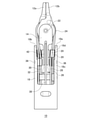
- FIG. 2 is a front view of the forceps device of FIG. 1 as viewed from the A direction.
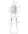
- FIG. 3 is a side view of the forceps device of FIG. 1 as viewed from the B direction.
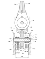
- FIG. 4 is a side view of the forceps device of FIG. 1 as viewed from the C direction.
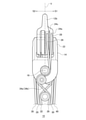
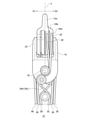
- the forceps device 10 shown in each figure includes a pair of grip portions 12a and 12b, a support 14 that holds the pair of grip portions 12a and 12b, and a first rotation shaft 16 that rotatably supports the support 14.
- a base component 18 for holding the first rotating shaft 16, four guide pulleys 20 arranged coaxially with the first rotating shaft 16, and a pair of grip portions 12a and 12b are rotatably supported and supported.
- the wires 26, 28, 30, 32 and the wires 38, 40 for rotating the support 14 about the first rotation shaft 16 are provided.
- FIG. 5 is a cross-sectional view taken along the line DD of the forceps device 10 shown in FIG.
- FIG. 6 is an enlarged view of the region R of FIG.
- the guide pulley 20 has a first rotating shaft via a cylindrical annular portion 14a that is a part of the support 14 so as to be inclined with respect to the first rotating shaft 16. It is rotatably supported by 16.
- each of the wires 26, 28, 30, and 32 has a substantially smaller fleet angle with respect to the guide pulley 20, and is less likely to interfere with the edge 20b of the guide groove 20a of the guide pulley 20.
- the guide pulley 20 may be directly supported by the first rotating shaft 16 without going through the support body 14.
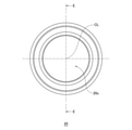
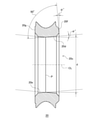
- FIG. 7 is a front view of the guide pulley 20 according to the present embodiment.
- FIG. 8 is a cross-sectional view taken along the line EE of the guide pulley 20 shown in FIG.
- the inner peripheral surface 20d is inclined with respect to the center line CL of the circular opening 20c through which the first rotation shaft 16 penetrates.
- the inner peripheral surface 20d slides with respect to the annular portion 14a of the support 14 into which the first rotation shaft 16 is inserted.
- the guide pulley 20 is autonomously tilted by the force received from the wire having the fleet angle.
- the inner peripheral surface 20d of the guide pulley 20 slides directly on the outer peripheral surface of the first rotating shaft 16.
- the inner peripheral surface 20d is formed so that the inner diameter d gradually expands as the guide pulley 20 is orthogonal to the center line CL and is separated from the plane P having the smallest inner diameter d along the center line CL. ing.
- the inner peripheral surface 20d may be formed as a conical shape, a mortar shape, or a tapered surface.
- the inner peripheral surface 20e on the opposite side of the flat surface P with the inner peripheral surface 20d is also processed into the same shape as the inner peripheral surface 20d.
- the guide pulley 20 has an angle ⁇ formed by the inner peripheral surface 20d and the inner peripheral surface 20e and the center line CL in the range of 3 to 7 °. Further, one end surface 20f of the guide pulley 20 is inclined at an angle ⁇ with respect to the plane P, and the angle formed by the one end surface 20f and the inner peripheral surface 20d is 90 °. Further, the other end surface 20g of the guide pulley 20 is parallel to the plane P (orthogonal to the center line CL). Therefore, the guide pulley 20 is an annular member whose left and right sides are asymmetrical with the plane P in between.
- two guide pulleys 20 are arranged adjacent to each other on both sides of the support 14. Then, as shown in FIG. 6, when the two guide pulleys 20 are arranged side by side and mounted on the annular portion 14a, the other end faces 20g are opposed to each other. As a result, one of the two adjacent guide pulleys 20 (guide pulley 20B) abuts on the support 14 in an inclined state, and the other of the two adjacent guide pulleys 20 (guide pulley 20A) is in an inclined state. It abuts on the base component 18. As a result, when the guide pulley 20 is tilted, the position of the guide pulley 20 in the first rotation axis direction X is accurately determined.
- each guide pulley 20 is inclined with respect to the first rotation shaft 16 so that the plurality of hung wires 26 and 28 spread outward toward the outer circumference of the jaw pulley 24. ..
- the interference of the wire in the guide pulley 20 can be suppressed.
- the base component 18 As shown in FIGS. 2 and 5, the base component 18 according to the present embodiment is held by a pair of arms 18a and 18b that hold both ends of the first rotating shaft 16 and a pair of arms 18a and 18b. It has a third rotating shaft 36 that rotatably supports the four guide pulleys 34 located upstream of the guide pulley 20. The third rotating shaft 36 according to the present embodiment is provided on each of the pair of arms 18a and 18b.
- the arms 18a and 18b have a thinner tip portion 18d that holds the first rotating shaft 16 than a root portion 18c that holds the third rotating shaft 36. In other words, the distance between the tip portions 18d is wider than the distance between the root portions 18c. As a result, as shown in FIG. 3, even when the wires 26 and 28 having the fleet angle are bent around the first rotation axis 16 together with the support 14 (in the direction of arrow F in FIG. 3), the arm 18a , 18b is less likely to interfere.
- the circumferential width W1 of the tip portion 18d of the arm 18a (arm 18b) is narrower than the circumferential width W2 of the root portion 18c.
- the width of the root portion 18c in the circumferential direction is made larger than the width of the tip portion 18d in the circumferential direction while forming a U-shaped relief portion in the tip portion 18d where interference with the wire needs to be considered. It is possible to suppress the decrease in the rigidity of the arm.
- the outer diameter G1 of the jaw pulley 24 according to the present embodiment is larger than the distance G2 between the root portions 18c of the pair of arms 18a and 18b. That is, the forceps device 10 according to the present embodiment can adopt a jaw pulley 24 having a large outer diameter for the size of the inner diameter of the cylindrical base component 18.
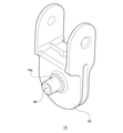
- FIG. 9 is a perspective view of the support according to the present embodiment.
- the forceps device 10 rotates the pair of grip portions 12a and 12b, the support 14 holding the pair of grip portions 12a and 12b, and the support body 14. It includes a first rotating shaft 16 that can be supported, a base component 18 that holds the first rotating shaft 16, and a plurality of guide pulleys 20 that are arranged coaxially with the first rotating shaft 16.
- the support 14 has an annular portion 14a as a cylindrical portion through which the first rotating shaft 16 penetrates.
- the plurality of guide pulleys 20 are rotatably supported on the outer periphery of the annular portion 14a.
- the rotating shaft is not limited to one that rotates by itself, but may be a shaft that is fixed to another member as long as it serves as an axis when the supporting member rotates.
- the support 14 in a state where a plurality of guide pulleys 20 are supported on the outer periphery of the annular portion 14a is held by the base component 18 via the first rotation shaft 16. To. Therefore, it is easy to improve the assembling property as compared with the case where the support 14 is directly held by the base component 18.
- the base component 18 has a pair of arms 18a and 18b facing each other. Further, the first rotating shaft 16 is firmly fixed by press-fitting both ends in the axial direction with respect to the pair of arms 18a and 18b. As a result, the tips of the pair of arms 18a and 18b that can be free ends are fixed to each other by the rotation shaft, so that the rigidity of the entire base component 18 is increased.
- each of the wires 26, 28, 30, and 32 is for transmitting the driving force for operating the grip portion 12a and the grip portion 12b.
- the wire 26 and the wire 32 are hooked on the jaw pulley 24 of the grip portion 12b, and the grip portion 12b moves in the opening direction when the wire 26 is pulled, and moves in the closing direction when the wire 32 is pulled.
- the wire 28 and the wire 30 are hooked on the jaw pulley 24 of the grip portion 12a, and the grip portion 12a moves in the closing direction when the wire 28 is pulled, and moves in the opening direction when the wire 30 is pulled.
- each of the four guide pulleys 20 is hung with the corresponding wires 26, 28, 30, 32.
- the wires 26, 28, 30, 32 are hung on the corresponding guide pulley 20 so that the normal force received by the support 14 from the first rotating shaft 16 when operating the grip portions 12a, 12b is reduced. .. More specifically, the wires 26, 28, 30, 32 pass between the corresponding guide pulley 20 and the guide pulley 34, as shown in FIG. 2, and the lower side of the guide pulley 20 (the first rotating shaft 16). It is sandwiched and hung from the grip portion (opposite side to the grip portions 12a and 12b).
- the tension exerts a force on the support 14 via the guide pulley 20.
- the tension generated by the wires 26, 28, 30, 32 applies a force toward the grip portions 12a, 12b to the support 14.
- the support 14 is integrally formed with a support pulley 42 on which wires 38 and 40 for transmitting a driving force for rotating the support around the first rotation shaft 16 are applied. Therefore, when the support 14 is to be rotated by pulling one of the wires 38 and 40, the support 14 is moved to the first rotation shaft 16 side by the tension of the wires 38 and 40 applied to the support pulley 42. Be pressed. At that time, a normal force received by the support 14 from the first rotation shaft 16 is generated, which contributes to an increase in the frictional force.
- the upward force of FIG. 2 is applied to the guide pulley 20 by the tension of the wires 26, 28, 30, 32 when operating the grip portions 12a and 12b as described above. Occur.
- the frictional force when the support 14 rotates with respect to the first rotating shaft 16 is reduced.
- the operation of the grip portions 12a and 12b becomes smooth, and the controllability of the forceps device 10 is improved.
- FIG. 10 is a diagram showing a flowchart for explaining a method of manufacturing a forceps device according to the present embodiment.
- the support 14 holding the grip portions 12a and 12b is prepared (S10).
- a plurality of guide pulleys 20 are mounted on the outer periphery of the annular portion 14a in which the through hole 44 (see FIG. 5) into which the first rotating shaft 16 that rotatably supports the support 14 is inserted is formed. (S12).
- the support 14 is positioned so that the holes 18e and 18f and the through holes 44 are linearly aligned with respect to the base component 18 in which the holes 18e and 18f into which the first rotation shaft 16 is inserted are formed. (S14). Then, the first rotary shaft 16 is inserted from the hole 18e, and finally both ends of the first rotary shaft 16 are press-fitted into the holes 18 and 18f of the base component 18, so that the first rotary shaft 16 is formed. It is firmly fixed to the base component 18 (S16). The step of hooking the wire to each pulley may be performed at a timing that does not interfere with the above-mentioned manufacturing.
- the process of sandwiching the support between the divided base parts and then joining the base parts to each other becomes unnecessary.
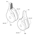
- FIG. 11 is a perspective view showing how a pair of jaw parts according to the present embodiment are combined facing each other.
- the jaw parts 50A and 50B shown in FIG. 11 are parts having substantially the same shape as each other.
- the jaw parts 50A and 50B have a grip portion 12a and a grip portion 12b that grip the object by moving relative to each other.
- the grip portion 12a is connected to the jaw pulley 24a (first grip portion pulley) and the jaw pulley 24b (second grip portion pulley) formed in a bifurcation, and integrally constitutes the jaw component 50A.
- the grip portion 12b is connected to the jaw pulley 24c (third grip portion pulley) and the jaw pulley 24d (fourth grip portion pulley) formed in a bifurcation, and integrally constitutes the jaw component 50B.
- FIG. 12 is a perspective view of the forceps device 10 shown in FIG. 1 as viewed from the H1 direction.
- FIG. 13 is a perspective view of the forceps device 10 shown in FIG. 1 as viewed from the H2 direction.
- FIG. 14 is a perspective view of the forceps device 10 shown in FIG. 1 as viewed from the H3 direction.
- FIG. 15 is a perspective view of the forceps device 10 shown in FIG. 1 as viewed from a direction opposite to the H2 direction.
- the direction from H1 to H3 is a direction in the horizontal plane H including the first rotation axis 16. Further, in each of FIGS. 12 to 15, the base component 18 is not shown.
- the jaw pulley 24a, the jaw pulley 24c, the jaw pulley 24b, and the jaw pulley 24d are rotatably supported by the second rotating shaft 22 in this order.
- the guide pulley 20A, the guide pulley 20B, the guide pulley 20C and the guide pulley 20D are rotatably supported by the first rotating shaft 16 in this order.
- the wires 26, 28, 30 and 32 as gripping wire for transmitting the driving force for opening and closing the gripping portions 12a and 12b have other pulleys between the plurality of guide pulleys 20A to 20D and the gripping portions 12a and 12b. It hangs without going through.
- the driving force is input from the actuator unit outside the forceps device 10.
- the distance between the first rotating shaft 16 and the second rotating shaft 22 can be shortened, so that the torque (operating force) by the grip portions 12a and 12b can be increased.
- the forceps device 10 having good controllability of the grip portions 12a and 12b.
- the wire 26 is hung between the guide pulley 20A and the jaw pulley 24c.
- the wire 28 is hung between the guide pulley 20B and the jaw pulley 24a.
- the wire 30 is hung between the guide pulley 20C and the jaw pulley 24b.
- the wire 32 is hung between the guide pulley 20D and the jaw pulley 24d.
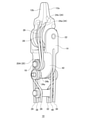
- FIG. 16 is a diagram in which the base component 18 of the forceps device 10 shown in FIG. 3 is not shown.
- FIG. 17 is a diagram in which the base component of the forceps device 10 shown in FIG. 4 is not shown.
- the wire 26 is attached to one side S1 of the guide pulley 20A with reference to the vertical cross section V including the first rotating shaft 16 and orthogonal to the second rotating shaft 22. After being hung, it is fixed to the jaw pulley 24c on one side S1 of the vertical cross section V.
- the wire 28 is hooked on one side S1 of the guide pulley 20B with reference to the vertical cross section V, and then fixed to the jaw pulley 24a on one side S1 of the vertical cross section V.
- the wire 30 is hung on the other side S2 of the guide pulley 20C with reference to the vertical cross section V, and then fixed to the jaw pulley 24b on the other side of the vertical cross section V.
- the wire 32 is hooked on the other side S2 of the guide pulley 20D with reference to the vertical cross section V, and then fixed to the jaw pulley 24d on the other side S2 of the vertical cross section V.
- the four grip wires are fixed to the corresponding four grip pulleys without crossing each other.
- the four gripping wires hanging on the guide pulleys 20A to 20D are fixed to the corresponding four gripping pulleys in a state where the fleet angle is small.
- the forceps device 10 has a guide pulley 34a on the upstream side (opposite side of the grip portion) of the guide pulley 20A and on the other side S2 of the vertical cross section V, and a vertical cross section V on the upstream side of the guide pulley 20B.
- any of the wires 26, 28, 30, 32 comes into contact with any of the guide pulleys 20A to 20D.
- the controllability when rotating the support 14 is stable. More specifically, when the support 14 is bent toward the other side S2 from the state shown in FIG. 16, the wires 26 and 28 come into contact with the guide pulleys 20A and 20B, respectively. Further, when the support 14 is bent toward one side S1 from the state shown in FIG. 17, the wires 30 and 32 come into contact with the guide pulleys 20C and 20D, respectively.
- the present invention has been described above with reference to the above-described embodiment, the present invention is not limited to the above-described embodiment, and the present invention is not limited to the above-described embodiment, and the present invention may be a combination or substitution of the configurations of the embodiments as appropriate. It is included in the present invention. Further, it is also possible to appropriately rearrange the combinations and the order of processing in the embodiment based on the knowledge of those skilled in the art, and to add modifications such as various design changes to the embodiments, and such modifications are added. The embodiments described above may also be included in the scope of the present invention.
- the present invention can be used as a manipulator for a surgical robot.
- 10 forceps device, 12a, 12b grip, 14 support 16 first rotation shaft, 18 base parts, 20, 20A, 20B, 20C, 20D guide pulley, 22 second rotation shaft, 24, 24a, 24b, 24c, 24d jaw pulley, 26, 28, 30, 32 wire, 34, 34a, 34b, 34c, 34d guide pulley, 38 wire, 42 support pulley.
Landscapes
- Health & Medical Sciences (AREA)
- Surgery (AREA)
- Life Sciences & Earth Sciences (AREA)
- Engineering & Computer Science (AREA)
- Medical Informatics (AREA)
- Biomedical Technology (AREA)
- Heart & Thoracic Surgery (AREA)
- Nuclear Medicine, Radiotherapy & Molecular Imaging (AREA)
- Molecular Biology (AREA)
- Animal Behavior & Ethology (AREA)
- General Health & Medical Sciences (AREA)
- Public Health (AREA)
- Veterinary Medicine (AREA)
- Robotics (AREA)
- Ophthalmology & Optometry (AREA)
- Manipulator (AREA)
- Surgical Instruments (AREA)
Abstract
Description
図1は、本実施の形態に係る鉗子装置の斜視図である。図2は、図1の鉗子装置をA方向から見た正面図である。図3は、図1の鉗子装置をB方向から見た側面図である。図4は、図1の鉗子装置をC方向から見た側面図である。
図5は、図3に示す鉗子装置10のD-D断面図である。図6は、図5の領域Rの拡大図である。図5及び図6に示すように、ガイドプーリ20は、第1の回転軸16に対して傾斜するように、支持体14の一部である円筒の環状部14aを介して第1の回転軸16に回転可能に支持されている。これにより、ワイヤ26,28,30,32のそれぞれは、ガイドプーリ20に対する実質的なフリートアングルが小さくなり、ガイドプーリ20のガイド溝20aのエッジ20bと干渉しにくくなる。なお、ガイドプーリ20は、支持体14を介さずに第1の回転軸16に直接支持されていてもよい。
図9は、本実施の形態に係る支持体の斜視図である。図5や図6に示すように、本実施の形態に係る鉗子装置10は、一対の把持部12a,12bと、一対の把持部12a,12bを保持する支持体14と、支持体14を回転可能に支持する第1の回転軸16と、第1の回転軸16を保持するベース部品18と、第1の回転軸16と同軸に配置されている複数のガイドプーリ20と、を備える。支持体14は、図9に示すように、第1の回転軸16が貫通する筒状部としての環状部14aを有する。複数のガイドプーリ20は、環状部14aの外周に回転可能に支持されている。なお、回転軸とは、自身が回転するものだけではなく、支持する部材が回転する際の軸となるものであればよく、他の部材に対して固定されている軸であってもよい。
次に、本実施の形態に係る鉗子装置10の製造方法について説明する。図10は、本実施の形態に係る鉗子装置の製造方法を説明するためのフローチャートを示す図である。この方法は、はじめに、把持部12a,12bを保持している支持体14を準備する(S10)。次に、支持体14を回転可能に支持する第1の回転軸16が挿入される貫通孔44(図5参照)が形成されている環状部14aの外周に、複数のガイドプーリ20を装着する(S12)。次に、第1の回転軸16が挿入される穴18e,18fが形成されているベース部品18に対して、穴18e,18fと貫通孔44とが直線的に並ぶように支持体14を位置決めする(S14)。そして、穴18eから第1の回転軸16を挿入し、最終的に第1の回転軸16の両端をベース部品18の穴18,18fに対して圧入することで、第1の回転軸16がベース部品18に対して強固に固定される(S16)。なお、各プーリにワイヤを掛ける工程は、前述の製造の妨げにならないタイミングで行えばよい。
次に、本実施の形態に係る把持部を構成するジョー部品について詳述する。図11は、本実施の形態に係る一対のジョー部品を向かい合わせに組み合わせる様子を示す斜視図である。図11に示すジョー部品50A,50Bは、互いにほぼ同じ形状の部品である。ジョー部品50A,50Bは、互いが相対的に動くことで対象物を把持する把持部12a及び把持部12bを有している。把持部12aは、二股に形成されているジョープーリ24a(第1の把持部プーリ)及びジョープーリ24b(第2の把持部プーリ)と連なり、一体的にジョー部品50Aを構成する。また、把持部12bは、二股に形成されているジョープーリ24c(第3の把持部プーリ)及びジョープーリ24d(第4の把持部プーリ)と連なり、一体的にジョー部品50Bを構成する。
次に、本実施の形態に係るワイヤ26,28,30,32の各プーリへの掛かり方について詳述する。ワイヤ26は、ガイドプーリ20Aとジョープーリ24cとの間に掛けられている。ワイヤ28は、ガイドプーリ20Bとジョープーリ24aとの間に掛けられている。ワイヤ30は、ガイドプーリ20Cとジョープーリ24bとの間に掛けられている。ワイヤ32は、ガイドプーリ20Dとジョープーリ24dとの間に掛けられている。
Claims (8)
- 把持部と、
前記把持部を保持する支持体と、
前記支持体を回転可能に支持する第1の回転軸と、
前記第1の回転軸を保持するベース部品と、
前記第1の回転軸と同軸に配置されている複数のガイドプーリと、
前記複数のガイドプーリと前記把持部との間に他のプーリを介さずに掛かり、前記把持部を動作させる駆動力を伝達する複数の把持部ワイヤと、
前記支持体に設けられた支持体プーリと、
前記支持体プーリに掛かり、前記支持体を前記第1の回転軸を中心に回転させる駆動力を伝達する支持体ワイヤと、
を備える鉗子装置。 - 前記把持部は、互いが相対的に動くことで対象物を把持する第1の把持部及び第2の把持部を有し、
前記第1の把持部は、二股に形成されている第1の把持部プーリ及び第2の把持部プーリと連なり、
前記第2の把持部は、二股に形成されている第3の把持部プーリ及び第4の把持部プーリと連なり、
前記第1の把持部プーリ、前記第3の把持部プーリ、前記第2の把持部プーリ及び前記第4の把持部プーリを、この順で回転可能に支持する第2の回転軸を更に備えることを特徴とする請求項1に記載の鉗子装置。 - 把持部と、
前記把持部を保持する支持体と、
前記支持体を回転可能に支持する第1の回転軸と、
前記第1の回転軸を保持するベース部品と、
前記第1の回転軸と同軸に配置されている複数のガイドプーリと、
前記複数のガイドプーリと前記把持部との間に他のプーリを介さずに掛かり、前記把持部を動作させる駆動力を伝達する複数の把持部ワイヤと、を備え、
前記把持部は、互いが相対的に動くことで対象物を把持する第1の把持部及び第2の把持部を有し、
前記第1の把持部は、二股に形成されている第1の把持部プーリ及び第2の把持部プーリと連なり、
前記第2の把持部は、二股に形成されている第3の把持部プーリ及び第4の把持部プーリと連なり、
前記第1の把持部プーリ、前記第3の把持部プーリ、前記第2の把持部プーリ及び前記第4の把持部プーリを、この順で回転可能に支持する第2の回転軸を更に備えることを特徴とする鉗子装置。 - 前記支持体は、前記第1の回転軸が貫通する筒状部を有し、
前記複数のガイドプーリは、前記筒状部の外周に回転可能に支持されていることを特徴とする請求項2又は3に記載の鉗子装置。 - 前記複数のガイドプーリは、第1~第4のガイドプーリを有し、
前記複数の把持部ワイヤは、前記第1~第4のガイドプーリと前記第1~第4の把持部プーリとの間に他のプーリを介さずに掛けられていることを特徴とする請求項4に記載の鉗子装置。 - 前記複数の把持部ワイヤは、
前記第1のガイドプーリと前記第3の把持部プーリとの間に掛けられた第1の把持部ワイヤと、
前記第2のガイドプーリと前記第1の把持部プーリとの間に掛けられた第2の把持部ワイヤと、
前記第3のガイドプーリと前記第2の把持部プーリとの間に掛けられた第3の把持部ワイヤと、
前記第4のガイドプーリと前記第4の把持部プーリとの間に掛けられた第4の把持部ワイヤと、
を有することを特徴とする請求項5に記載の鉗子装置。 - 前記第1の把持部ワイヤは、前記第1の回転軸を含み前記第2の回転軸と直交する鉛直断面を基準に、前記第1のガイドプーリの一方の側に掛けられた後に、前記鉛直断面の一方の側にある前記第3の把持部プーリに固定されており、
前記第2の把持部ワイヤは、前記鉛直断面を基準に、前記第2のガイドプーリの一方の側に掛けられた後に、前記鉛直断面の一方の側にある前記第1の把持部プーリに固定されており、
前記第3の把持部ワイヤは、前記鉛直断面を基準に、前記第3のガイドプーリの他方の側に掛けられた後に、前記鉛直断面の他方の側にある前記第2の把持部プーリに固定されており、
前記第4の把持部ワイヤは、前記鉛直断面を基準に、前記第4のガイドプーリの他方の側に掛けられた後に、前記鉛直断面の他方の側にある前記第4の把持部プーリに固定されている、
ことを特徴とする請求項6に記載の鉗子装置。 - 前記第1のガイドプーリの上流側であって前記鉛直断面の他方の側にある第5のガイドプーリと、
前記第2のガイドプーリの上流側であって前記鉛直断面の他方の側にある第6のガイドプーリと、
前記第3のガイドプーリの上流側であって前記鉛直断面の一方の側にある第7のガイドプーリと、
前記第4のガイドプーリの上流側であって前記鉛直断面の一方の側にある第8のガイドプーリと、
を備えることを特徴とする請求項7に記載の鉗子装置。
Priority Applications (5)
| Application Number | Priority Date | Filing Date | Title |
|---|---|---|---|
| CN202080103538.9A CN115916089B (zh) | 2020-09-10 | 2020-09-10 | 钳子装置 |
| JP2021507719A JP6896317B1 (ja) | 2020-09-10 | 2020-09-10 | 鉗子装置 |
| EP20953279.5A EP4205687A4 (en) | 2020-09-10 | 2020-09-10 | PLIERS DEVICE |
| PCT/JP2020/034370 WO2022054214A1 (ja) | 2020-09-10 | 2020-09-10 | 鉗子装置 |
| US18/181,034 US20230210546A1 (en) | 2020-09-10 | 2023-03-09 | Forceps device |
Applications Claiming Priority (1)
| Application Number | Priority Date | Filing Date | Title |
|---|---|---|---|
| PCT/JP2020/034370 WO2022054214A1 (ja) | 2020-09-10 | 2020-09-10 | 鉗子装置 |
Related Child Applications (1)
| Application Number | Title | Priority Date | Filing Date |
|---|---|---|---|
| US18/181,034 Continuation US20230210546A1 (en) | 2020-09-10 | 2023-03-09 | Forceps device |
Publications (1)
| Publication Number | Publication Date |
|---|---|
| WO2022054214A1 true WO2022054214A1 (ja) | 2022-03-17 |
Family
ID=76540437
Family Applications (1)
| Application Number | Title | Priority Date | Filing Date |
|---|---|---|---|
| PCT/JP2020/034370 Ceased WO2022054214A1 (ja) | 2020-09-10 | 2020-09-10 | 鉗子装置 |
Country Status (5)
| Country | Link |
|---|---|
| US (1) | US20230210546A1 (ja) |
| EP (1) | EP4205687A4 (ja) |
| JP (1) | JP6896317B1 (ja) |
| CN (1) | CN115916089B (ja) |
| WO (1) | WO2022054214A1 (ja) |
Families Citing this family (2)
| Publication number | Priority date | Publication date | Assignee | Title |
|---|---|---|---|---|
| CN118555939A (zh) * | 2022-01-17 | 2024-08-27 | 瑞德医疗机器股份有限公司 | 镊子装置 |
| WO2025099560A1 (en) * | 2023-11-08 | 2025-05-15 | Covidien Lp | Surgical instrument with wristed jaws having idler pulley for zero fleet angle |
Citations (5)
| Publication number | Priority date | Publication date | Assignee | Title |
|---|---|---|---|---|
| US20150127045A1 (en) | 2012-07-17 | 2015-05-07 | Richard Wolf Gmbh | Endoscopic instrument |
| CN105212987A (zh) * | 2015-09-29 | 2016-01-06 | 哈尔滨思哲睿智能医疗设备有限公司 | 一种手术微器械的末端执行机构 |
| CN107928792A (zh) * | 2017-12-11 | 2018-04-20 | 哈尔滨思哲睿智能医疗设备有限公司 | 一种用于微创外科机器人用多自由度持针器 |
| US20190099231A1 (en) * | 2017-09-29 | 2019-04-04 | Ethicon Llc | Power axle wrist for robotic surgical tool |
| US20200054405A1 (en) * | 2018-08-17 | 2020-02-20 | Auris Health, Inc. | Bipolar medical instrument |
Family Cites Families (7)
| Publication number | Priority date | Publication date | Assignee | Title |
|---|---|---|---|---|
| EP2204126B1 (en) * | 2006-10-13 | 2011-11-23 | Terumo Kabushiki Kaisha | Manipulator |
| US8771270B2 (en) * | 2008-07-16 | 2014-07-08 | Intuitive Surgical Operations, Inc. | Bipolar cautery instrument |
| JP6701172B2 (ja) * | 2014-08-13 | 2020-05-27 | コヴィディエン リミテッド パートナーシップ | 機械的利益把握のロボット制御 |
| JP2017093818A (ja) * | 2015-11-25 | 2017-06-01 | リバーフィールド株式会社 | 撮像システムおよび固定具 |
| GB201521803D0 (en) * | 2015-12-10 | 2016-01-27 | Cambridge Medical Robotics Ltd | Surgical instrument articulation |
| CN110382179A (zh) * | 2017-02-27 | 2019-10-25 | 朝日英达科株式会社 | 操纵器 |
| JP6850517B1 (ja) * | 2020-09-10 | 2021-03-31 | リバーフィールド株式会社 | 鉗子装置及び鉗子装置の製造方法 |
-
2020
- 2020-09-10 JP JP2021507719A patent/JP6896317B1/ja active Active
- 2020-09-10 EP EP20953279.5A patent/EP4205687A4/en not_active Ceased
- 2020-09-10 CN CN202080103538.9A patent/CN115916089B/zh active Active
- 2020-09-10 WO PCT/JP2020/034370 patent/WO2022054214A1/ja not_active Ceased
-
2023
- 2023-03-09 US US18/181,034 patent/US20230210546A1/en not_active Abandoned
Patent Citations (5)
| Publication number | Priority date | Publication date | Assignee | Title |
|---|---|---|---|---|
| US20150127045A1 (en) | 2012-07-17 | 2015-05-07 | Richard Wolf Gmbh | Endoscopic instrument |
| CN105212987A (zh) * | 2015-09-29 | 2016-01-06 | 哈尔滨思哲睿智能医疗设备有限公司 | 一种手术微器械的末端执行机构 |
| US20190099231A1 (en) * | 2017-09-29 | 2019-04-04 | Ethicon Llc | Power axle wrist for robotic surgical tool |
| CN107928792A (zh) * | 2017-12-11 | 2018-04-20 | 哈尔滨思哲睿智能医疗设备有限公司 | 一种用于微创外科机器人用多自由度持针器 |
| US20200054405A1 (en) * | 2018-08-17 | 2020-02-20 | Auris Health, Inc. | Bipolar medical instrument |
Non-Patent Citations (1)
| Title |
|---|
| See also references of EP4205687A4 |
Also Published As
| Publication number | Publication date |
|---|---|
| JP6896317B1 (ja) | 2021-06-30 |
| US20230210546A1 (en) | 2023-07-06 |
| JPWO2022054214A1 (ja) | 2022-03-17 |
| CN115916089A (zh) | 2023-04-04 |
| EP4205687A4 (en) | 2024-02-21 |
| EP4205687A1 (en) | 2023-07-05 |
| CN115916089B (zh) | 2025-04-18 |
Similar Documents
| Publication | Publication Date | Title |
|---|---|---|
| US12310691B2 (en) | Multi-cable medical instrument | |
| CN100473870C (zh) | 动力传递机构和操纵装置 | |
| JP6896317B1 (ja) | 鉗子装置 | |
| KR101252279B1 (ko) | 수술기구 | |
| WO2018177038A1 (zh) | 手术机器人用蛇形关节、手术器械及内窥镜 | |
| CN109952175B (zh) | 利用线的机器人关节驱动装置、包括此的内窥镜机器人装置及医疗用机器人装置 | |
| JP6850517B1 (ja) | 鉗子装置及び鉗子装置の製造方法 | |
| CN115835828A (zh) | 外科手术机械臂、柔性臂以及柔性关节 | |
| CN116509551A (zh) | 手术器械的末端执行机构及手术器械 | |
| JP6943522B1 (ja) | 鉗子装置及びベース部品 | |
| JPWO2018203425A1 (ja) | 医療用処置具および手術システム | |
| KR20100099817A (ko) | 수술기구 | |
| JP2018187028A (ja) | 駆動部材、駆動機構、および駆動機構の製造方法 | |
| WO2018207809A1 (ja) | ワイヤ操作装置およびそのワイヤの拘束方法 | |
| CN116492020A (zh) | 一种手术器械组件、装置及机器人 | |
| WO2023135792A1 (ja) | 鉗子装置 | |
| JP6867073B1 (ja) | 鉗子装置 | |
| WO2023135793A1 (ja) | 鉗子装置 | |
| WO2023135791A1 (ja) | 鉗子装置 | |
| JP6895007B2 (ja) | 医療用処置具 | |
| WO2021166217A1 (ja) | 鉗子装置 | |
| CN118476843A (zh) | 一种多自由度器械钳用关节机构、器械钳及手术机器人 | |
| FR3160607A3 (fr) | Système automatisé pour la chirurgie mini-invasive assistée par robot |
Legal Events
| Date | Code | Title | Description |
|---|---|---|---|
| ENP | Entry into the national phase |
Ref document number: 2021507719 Country of ref document: JP Kind code of ref document: A |
|
| 121 | Ep: the epo has been informed by wipo that ep was designated in this application |
Ref document number: 20953279 Country of ref document: EP Kind code of ref document: A1 |
|
| ENP | Entry into the national phase |
Ref document number: 2020953279 Country of ref document: EP Effective date: 20230330 |
|
| NENP | Non-entry into the national phase |
Ref country code: DE |
|
| WWG | Wipo information: grant in national office |
Ref document number: 202080103538.9 Country of ref document: CN |
|
| WWW | Wipo information: withdrawn in national office |
Ref document number: 2020953279 Country of ref document: EP |