WO2022054639A1 - 空間充填材およびその製造方法、ならびに空間充填構造体 - Google Patents
空間充填材およびその製造方法、ならびに空間充填構造体 Download PDFInfo
- Publication number
- WO2022054639A1 WO2022054639A1 PCT/JP2021/031888 JP2021031888W WO2022054639A1 WO 2022054639 A1 WO2022054639 A1 WO 2022054639A1 JP 2021031888 W JP2021031888 W JP 2021031888W WO 2022054639 A1 WO2022054639 A1 WO 2022054639A1
- Authority
- WO
- WIPO (PCT)
- Prior art keywords
- space
- space filler
- fiber
- reinforcing fibers
- thermoplastic resin
- Prior art date
- Legal status (The legal status is an assumption and is not a legal conclusion. Google has not performed a legal analysis and makes no representation as to the accuracy of the status listed.)
- Ceased
Links
Images


Classifications
-
- C—CHEMISTRY; METALLURGY
- C08—ORGANIC MACROMOLECULAR COMPOUNDS; THEIR PREPARATION OR CHEMICAL WORKING-UP; COMPOSITIONS BASED THEREON
- C08J—WORKING-UP; GENERAL PROCESSES OF COMPOUNDING; AFTER-TREATMENT NOT COVERED BY SUBCLASSES C08B, C08C, C08F, C08G or C08H
- C08J5/00—Manufacture of articles or shaped materials containing macromolecular substances
- C08J5/04—Reinforcing macromolecular compounds with loose or coherent fibrous material
- C08J5/047—Reinforcing macromolecular compounds with loose or coherent fibrous material with mixed fibrous material
- C08J5/048—Macromolecular compound to be reinforced also in fibrous form
-
- D—TEXTILES; PAPER
- D04—BRAIDING; LACE-MAKING; KNITTING; TRIMMINGS; NON-WOVEN FABRICS
- D04H—MAKING TEXTILE FABRICS, e.g. FROM FIBRES OR FILAMENTARY MATERIAL; FABRICS MADE BY SUCH PROCESSES OR APPARATUS, e.g. FELTS, NON-WOVEN FABRICS; COTTON-WOOL; WADDING ; NON-WOVEN FABRICS FROM STAPLE FIBRES, FILAMENTS OR YARNS, BONDED WITH AT LEAST ONE WEB-LIKE MATERIAL DURING THEIR CONSOLIDATION
- D04H1/00—Non-woven fabrics formed wholly or mainly of staple fibres or like relatively short fibres
- D04H1/40—Non-woven fabrics formed wholly or mainly of staple fibres or like relatively short fibres from fleeces or layers composed of fibres without existing or potential cohesive properties
- D04H1/58—Non-woven fabrics formed wholly or mainly of staple fibres or like relatively short fibres from fleeces or layers composed of fibres without existing or potential cohesive properties by applying, incorporating or activating chemical or thermoplastic bonding agents, e.g. adhesives
-
- D—TEXTILES; PAPER
- D21—PAPER-MAKING; PRODUCTION OF CELLULOSE
- D21H—PULP COMPOSITIONS; PREPARATION THEREOF NOT COVERED BY SUBCLASSES D21C OR D21D; IMPREGNATING OR COATING OF PAPER; TREATMENT OF FINISHED PAPER NOT COVERED BY CLASS B31 OR SUBCLASS D21G; PAPER NOT OTHERWISE PROVIDED FOR
- D21H13/00—Pulp or paper, comprising synthetic cellulose or non-cellulose fibres or web-forming material
- D21H13/10—Organic non-cellulose fibres
- D21H13/20—Organic non-cellulose fibres from macromolecular compounds obtained otherwise than by reactions only involving carbon-to-carbon unsaturated bonds
-
- B—PERFORMING OPERATIONS; TRANSPORTING
- B32—LAYERED PRODUCTS
- B32B—LAYERED PRODUCTS, i.e. PRODUCTS BUILT-UP OF STRATA OF FLAT OR NON-FLAT, e.g. CELLULAR OR HONEYCOMB, FORM
- B32B5/00—Layered products characterised by the non- homogeneity or physical structure, i.e. comprising a fibrous, filamentary, particulate or foam layer; Layered products characterised by having a layer differing constitutionally or physically in different parts
- B32B5/02—Layered products characterised by the non- homogeneity or physical structure, i.e. comprising a fibrous, filamentary, particulate or foam layer; Layered products characterised by having a layer differing constitutionally or physically in different parts characterised by structural features of a fibrous or filamentary layer
- B32B5/022—Non-woven fabric
-
- B—PERFORMING OPERATIONS; TRANSPORTING
- B32—LAYERED PRODUCTS
- B32B—LAYERED PRODUCTS, i.e. PRODUCTS BUILT-UP OF STRATA OF FLAT OR NON-FLAT, e.g. CELLULAR OR HONEYCOMB, FORM
- B32B5/00—Layered products characterised by the non- homogeneity or physical structure, i.e. comprising a fibrous, filamentary, particulate or foam layer; Layered products characterised by having a layer differing constitutionally or physically in different parts
- B32B5/02—Layered products characterised by the non- homogeneity or physical structure, i.e. comprising a fibrous, filamentary, particulate or foam layer; Layered products characterised by having a layer differing constitutionally or physically in different parts characterised by structural features of a fibrous or filamentary layer
- B32B5/08—Layered products characterised by the non- homogeneity or physical structure, i.e. comprising a fibrous, filamentary, particulate or foam layer; Layered products characterised by having a layer differing constitutionally or physically in different parts characterised by structural features of a fibrous or filamentary layer the fibres or filaments of a layer being of different substances, e.g. conjugate fibres, mixture of different fibres
-
- B—PERFORMING OPERATIONS; TRANSPORTING
- B32—LAYERED PRODUCTS
- B32B—LAYERED PRODUCTS, i.e. PRODUCTS BUILT-UP OF STRATA OF FLAT OR NON-FLAT, e.g. CELLULAR OR HONEYCOMB, FORM
- B32B5/00—Layered products characterised by the non- homogeneity or physical structure, i.e. comprising a fibrous, filamentary, particulate or foam layer; Layered products characterised by having a layer differing constitutionally or physically in different parts
- B32B5/02—Layered products characterised by the non- homogeneity or physical structure, i.e. comprising a fibrous, filamentary, particulate or foam layer; Layered products characterised by having a layer differing constitutionally or physically in different parts characterised by structural features of a fibrous or filamentary layer
- B32B5/12—Layered products characterised by the non- homogeneity or physical structure, i.e. comprising a fibrous, filamentary, particulate or foam layer; Layered products characterised by having a layer differing constitutionally or physically in different parts characterised by structural features of a fibrous or filamentary layer characterised by the relative arrangement of fibres or filaments of different layers, e.g. the fibres or filaments being parallel or perpendicular to each other
-
- B—PERFORMING OPERATIONS; TRANSPORTING
- B32—LAYERED PRODUCTS
- B32B—LAYERED PRODUCTS, i.e. PRODUCTS BUILT-UP OF STRATA OF FLAT OR NON-FLAT, e.g. CELLULAR OR HONEYCOMB, FORM
- B32B5/00—Layered products characterised by the non- homogeneity or physical structure, i.e. comprising a fibrous, filamentary, particulate or foam layer; Layered products characterised by having a layer differing constitutionally or physically in different parts
- B32B5/22—Layered products characterised by the non- homogeneity or physical structure, i.e. comprising a fibrous, filamentary, particulate or foam layer; Layered products characterised by having a layer differing constitutionally or physically in different parts characterised by the presence of two or more layers which are next to each other and are fibrous, filamentary, formed of particles or foamed
- B32B5/24—Layered products characterised by the non- homogeneity or physical structure, i.e. comprising a fibrous, filamentary, particulate or foam layer; Layered products characterised by having a layer differing constitutionally or physically in different parts characterised by the presence of two or more layers which are next to each other and are fibrous, filamentary, formed of particles or foamed one layer being a fibrous or filamentary layer
- B32B5/26—Layered products characterised by the non- homogeneity or physical structure, i.e. comprising a fibrous, filamentary, particulate or foam layer; Layered products characterised by having a layer differing constitutionally or physically in different parts characterised by the presence of two or more layers which are next to each other and are fibrous, filamentary, formed of particles or foamed one layer being a fibrous or filamentary layer another layer next to it also being fibrous or filamentary
- B32B5/265—Layered products characterised by the non- homogeneity or physical structure, i.e. comprising a fibrous, filamentary, particulate or foam layer; Layered products characterised by having a layer differing constitutionally or physically in different parts characterised by the presence of two or more layers which are next to each other and are fibrous, filamentary, formed of particles or foamed one layer being a fibrous or filamentary layer another layer next to it also being fibrous or filamentary characterised by one fibrous or filamentary layer being a non-woven fabric layer
- B32B5/266—Layered products characterised by the non- homogeneity or physical structure, i.e. comprising a fibrous, filamentary, particulate or foam layer; Layered products characterised by having a layer differing constitutionally or physically in different parts characterised by the presence of two or more layers which are next to each other and are fibrous, filamentary, formed of particles or foamed one layer being a fibrous or filamentary layer another layer next to it also being fibrous or filamentary characterised by one fibrous or filamentary layer being a non-woven fabric layer next to one or more non-woven fabric layers
-
- C—CHEMISTRY; METALLURGY
- C08—ORGANIC MACROMOLECULAR COMPOUNDS; THEIR PREPARATION OR CHEMICAL WORKING-UP; COMPOSITIONS BASED THEREON
- C08J—WORKING-UP; GENERAL PROCESSES OF COMPOUNDING; AFTER-TREATMENT NOT COVERED BY SUBCLASSES C08B, C08C, C08F, C08G or C08H
- C08J5/00—Manufacture of articles or shaped materials containing macromolecular substances
- C08J5/04—Reinforcing macromolecular compounds with loose or coherent fibrous material
- C08J5/0405—Reinforcing macromolecular compounds with loose or coherent fibrous material with inorganic fibres
- C08J5/043—Reinforcing macromolecular compounds with loose or coherent fibrous material with inorganic fibres with glass fibres
-
- D—TEXTILES; PAPER
- D04—BRAIDING; LACE-MAKING; KNITTING; TRIMMINGS; NON-WOVEN FABRICS
- D04H—MAKING TEXTILE FABRICS, e.g. FROM FIBRES OR FILAMENTARY MATERIAL; FABRICS MADE BY SUCH PROCESSES OR APPARATUS, e.g. FELTS, NON-WOVEN FABRICS; COTTON-WOOL; WADDING ; NON-WOVEN FABRICS FROM STAPLE FIBRES, FILAMENTS OR YARNS, BONDED WITH AT LEAST ONE WEB-LIKE MATERIAL DURING THEIR CONSOLIDATION
- D04H1/00—Non-woven fabrics formed wholly or mainly of staple fibres or like relatively short fibres
- D04H1/40—Non-woven fabrics formed wholly or mainly of staple fibres or like relatively short fibres from fleeces or layers composed of fibres without existing or potential cohesive properties
- D04H1/42—Non-woven fabrics formed wholly or mainly of staple fibres or like relatively short fibres from fleeces or layers composed of fibres without existing or potential cohesive properties characterised by the use of certain kinds of fibres insofar as this use has no preponderant influence on the consolidation of the fleece
- D04H1/4209—Inorganic fibres
- D04H1/4218—Glass fibres
-
- D—TEXTILES; PAPER
- D04—BRAIDING; LACE-MAKING; KNITTING; TRIMMINGS; NON-WOVEN FABRICS
- D04H—MAKING TEXTILE FABRICS, e.g. FROM FIBRES OR FILAMENTARY MATERIAL; FABRICS MADE BY SUCH PROCESSES OR APPARATUS, e.g. FELTS, NON-WOVEN FABRICS; COTTON-WOOL; WADDING ; NON-WOVEN FABRICS FROM STAPLE FIBRES, FILAMENTS OR YARNS, BONDED WITH AT LEAST ONE WEB-LIKE MATERIAL DURING THEIR CONSOLIDATION
- D04H1/00—Non-woven fabrics formed wholly or mainly of staple fibres or like relatively short fibres
- D04H1/40—Non-woven fabrics formed wholly or mainly of staple fibres or like relatively short fibres from fleeces or layers composed of fibres without existing or potential cohesive properties
- D04H1/54—Non-woven fabrics formed wholly or mainly of staple fibres or like relatively short fibres from fleeces or layers composed of fibres without existing or potential cohesive properties by welding together the fibres, e.g. by partially melting or dissolving
- D04H1/541—Composite fibres, e.g. sheath-core, sea-island or side-by-side; Mixed fibres
- D04H1/5418—Mixed fibres, e.g. at least two chemically different fibres or fibre blends
-
- D—TEXTILES; PAPER
- D04—BRAIDING; LACE-MAKING; KNITTING; TRIMMINGS; NON-WOVEN FABRICS
- D04H—MAKING TEXTILE FABRICS, e.g. FROM FIBRES OR FILAMENTARY MATERIAL; FABRICS MADE BY SUCH PROCESSES OR APPARATUS, e.g. FELTS, NON-WOVEN FABRICS; COTTON-WOOL; WADDING ; NON-WOVEN FABRICS FROM STAPLE FIBRES, FILAMENTS OR YARNS, BONDED WITH AT LEAST ONE WEB-LIKE MATERIAL DURING THEIR CONSOLIDATION
- D04H1/00—Non-woven fabrics formed wholly or mainly of staple fibres or like relatively short fibres
- D04H1/40—Non-woven fabrics formed wholly or mainly of staple fibres or like relatively short fibres from fleeces or layers composed of fibres without existing or potential cohesive properties
- D04H1/54—Non-woven fabrics formed wholly or mainly of staple fibres or like relatively short fibres from fleeces or layers composed of fibres without existing or potential cohesive properties by welding together the fibres, e.g. by partially melting or dissolving
- D04H1/542—Adhesive fibres
- D04H1/55—Polyesters
-
- D—TEXTILES; PAPER
- D04—BRAIDING; LACE-MAKING; KNITTING; TRIMMINGS; NON-WOVEN FABRICS
- D04H—MAKING TEXTILE FABRICS, e.g. FROM FIBRES OR FILAMENTARY MATERIAL; FABRICS MADE BY SUCH PROCESSES OR APPARATUS, e.g. FELTS, NON-WOVEN FABRICS; COTTON-WOOL; WADDING ; NON-WOVEN FABRICS FROM STAPLE FIBRES, FILAMENTS OR YARNS, BONDED WITH AT LEAST ONE WEB-LIKE MATERIAL DURING THEIR CONSOLIDATION
- D04H1/00—Non-woven fabrics formed wholly or mainly of staple fibres or like relatively short fibres
- D04H1/40—Non-woven fabrics formed wholly or mainly of staple fibres or like relatively short fibres from fleeces or layers composed of fibres without existing or potential cohesive properties
- D04H1/58—Non-woven fabrics formed wholly or mainly of staple fibres or like relatively short fibres from fleeces or layers composed of fibres without existing or potential cohesive properties by applying, incorporating or activating chemical or thermoplastic bonding agents, e.g. adhesives
- D04H1/587—Non-woven fabrics formed wholly or mainly of staple fibres or like relatively short fibres from fleeces or layers composed of fibres without existing or potential cohesive properties by applying, incorporating or activating chemical or thermoplastic bonding agents, e.g. adhesives characterised by the bonding agents used
-
- D—TEXTILES; PAPER
- D04—BRAIDING; LACE-MAKING; KNITTING; TRIMMINGS; NON-WOVEN FABRICS
- D04H—MAKING TEXTILE FABRICS, e.g. FROM FIBRES OR FILAMENTARY MATERIAL; FABRICS MADE BY SUCH PROCESSES OR APPARATUS, e.g. FELTS, NON-WOVEN FABRICS; COTTON-WOOL; WADDING ; NON-WOVEN FABRICS FROM STAPLE FIBRES, FILAMENTS OR YARNS, BONDED WITH AT LEAST ONE WEB-LIKE MATERIAL DURING THEIR CONSOLIDATION
- D04H1/00—Non-woven fabrics formed wholly or mainly of staple fibres or like relatively short fibres
- D04H1/70—Non-woven fabrics formed wholly or mainly of staple fibres or like relatively short fibres characterised by the method of forming fleeces or layers, e.g. reorientation of fibres
- D04H1/72—Non-woven fabrics formed wholly or mainly of staple fibres or like relatively short fibres characterised by the method of forming fleeces or layers, e.g. reorientation of fibres the fibres being randomly arranged
- D04H1/732—Non-woven fabrics formed wholly or mainly of staple fibres or like relatively short fibres characterised by the method of forming fleeces or layers, e.g. reorientation of fibres the fibres being randomly arranged by fluid current, e.g. air-lay
-
- D—TEXTILES; PAPER
- D21—PAPER-MAKING; PRODUCTION OF CELLULOSE
- D21H—PULP COMPOSITIONS; PREPARATION THEREOF NOT COVERED BY SUBCLASSES D21C OR D21D; IMPREGNATING OR COATING OF PAPER; TREATMENT OF FINISHED PAPER NOT COVERED BY CLASS B31 OR SUBCLASS D21G; PAPER NOT OTHERWISE PROVIDED FOR
- D21H13/00—Pulp or paper, comprising synthetic cellulose or non-cellulose fibres or web-forming material
- D21H13/10—Organic non-cellulose fibres
- D21H13/12—Organic non-cellulose fibres from macromolecular compounds obtained by reactions only involving carbon-to-carbon unsaturated bonds
-
- D—TEXTILES; PAPER
- D21—PAPER-MAKING; PRODUCTION OF CELLULOSE
- D21H—PULP COMPOSITIONS; PREPARATION THEREOF NOT COVERED BY SUBCLASSES D21C OR D21D; IMPREGNATING OR COATING OF PAPER; TREATMENT OF FINISHED PAPER NOT COVERED BY CLASS B31 OR SUBCLASS D21G; PAPER NOT OTHERWISE PROVIDED FOR
- D21H13/00—Pulp or paper, comprising synthetic cellulose or non-cellulose fibres or web-forming material
- D21H13/36—Inorganic fibres or flakes
- D21H13/38—Inorganic fibres or flakes siliceous
- D21H13/40—Inorganic fibres or flakes siliceous vitreous, e.g. mineral wool, glass fibres
-
- D—TEXTILES; PAPER
- D21—PAPER-MAKING; PRODUCTION OF CELLULOSE
- D21H—PULP COMPOSITIONS; PREPARATION THEREOF NOT COVERED BY SUBCLASSES D21C OR D21D; IMPREGNATING OR COATING OF PAPER; TREATMENT OF FINISHED PAPER NOT COVERED BY CLASS B31 OR SUBCLASS D21G; PAPER NOT OTHERWISE PROVIDED FOR
- D21H13/00—Pulp or paper, comprising synthetic cellulose or non-cellulose fibres or web-forming material
- D21H13/36—Inorganic fibres or flakes
- D21H13/46—Non-siliceous fibres, e.g. from metal oxides
- D21H13/50—Carbon fibres
-
- D—TEXTILES; PAPER
- D21—PAPER-MAKING; PRODUCTION OF CELLULOSE
- D21H—PULP COMPOSITIONS; PREPARATION THEREOF NOT COVERED BY SUBCLASSES D21C OR D21D; IMPREGNATING OR COATING OF PAPER; TREATMENT OF FINISHED PAPER NOT COVERED BY CLASS B31 OR SUBCLASS D21G; PAPER NOT OTHERWISE PROVIDED FOR
- D21H27/00—Special paper not otherwise provided for, e.g. made by multi-step processes
-
- F—MECHANICAL ENGINEERING; LIGHTING; HEATING; WEAPONS; BLASTING
- F01—MACHINES OR ENGINES IN GENERAL; ENGINE PLANTS IN GENERAL; STEAM ENGINES
- F01N—GAS-FLOW SILENCERS OR EXHAUST APPARATUS FOR MACHINES OR ENGINES IN GENERAL; GAS-FLOW SILENCERS OR EXHAUST APPARATUS FOR INTERNAL-COMBUSTION ENGINES
- F01N3/00—Exhaust or silencing apparatus having means for purifying, rendering innocuous, or otherwise treating exhaust
- F01N3/08—Exhaust or silencing apparatus having means for purifying, rendering innocuous, or otherwise treating exhaust for rendering innocuous
- F01N3/10—Exhaust or silencing apparatus having means for purifying, rendering innocuous, or otherwise treating exhaust for rendering innocuous by thermal or catalytic conversion of noxious components of exhaust
- F01N3/24—Exhaust or silencing apparatus having means for purifying, rendering innocuous, or otherwise treating exhaust for rendering innocuous by thermal or catalytic conversion of noxious components of exhaust characterised by constructional aspects of converting apparatus
- F01N3/28—Construction of catalytic reactors
- F01N3/2839—Arrangements for mounting catalyst support in housing, e.g. with means for compensating thermal expansion or vibration
- F01N3/2853—Arrangements for mounting catalyst support in housing, e.g. with means for compensating thermal expansion or vibration using mats or gaskets between catalyst body and housing
-
- B—PERFORMING OPERATIONS; TRANSPORTING
- B32—LAYERED PRODUCTS
- B32B—LAYERED PRODUCTS, i.e. PRODUCTS BUILT-UP OF STRATA OF FLAT OR NON-FLAT, e.g. CELLULAR OR HONEYCOMB, FORM
- B32B2250/00—Layers arrangement
- B32B2250/03—3 layers
-
- B—PERFORMING OPERATIONS; TRANSPORTING
- B32—LAYERED PRODUCTS
- B32B—LAYERED PRODUCTS, i.e. PRODUCTS BUILT-UP OF STRATA OF FLAT OR NON-FLAT, e.g. CELLULAR OR HONEYCOMB, FORM
- B32B2250/00—Layers arrangement
- B32B2250/20—All layers being fibrous or filamentary
-
- B—PERFORMING OPERATIONS; TRANSPORTING
- B32—LAYERED PRODUCTS
- B32B—LAYERED PRODUCTS, i.e. PRODUCTS BUILT-UP OF STRATA OF FLAT OR NON-FLAT, e.g. CELLULAR OR HONEYCOMB, FORM
- B32B2262/00—Composition or structural features of fibres which form a fibrous or filamentary layer or are present as additives
- B32B2262/02—Synthetic macromolecular fibres
- B32B2262/0276—Polyester fibres
- B32B2262/0284—Polyethylene terephthalate [PET] or polybutylene terephthalate [PBT]
-
- B—PERFORMING OPERATIONS; TRANSPORTING
- B32—LAYERED PRODUCTS
- B32B—LAYERED PRODUCTS, i.e. PRODUCTS BUILT-UP OF STRATA OF FLAT OR NON-FLAT, e.g. CELLULAR OR HONEYCOMB, FORM
- B32B2262/00—Composition or structural features of fibres which form a fibrous or filamentary layer or are present as additives
- B32B2262/10—Inorganic fibres
- B32B2262/101—Glass fibres
-
- B—PERFORMING OPERATIONS; TRANSPORTING
- B32—LAYERED PRODUCTS
- B32B—LAYERED PRODUCTS, i.e. PRODUCTS BUILT-UP OF STRATA OF FLAT OR NON-FLAT, e.g. CELLULAR OR HONEYCOMB, FORM
- B32B2307/00—Properties of the layers or laminate
- B32B2307/50—Properties of the layers or laminate having particular mechanical properties
- B32B2307/54—Yield strength; Tensile strength
-
- B—PERFORMING OPERATIONS; TRANSPORTING
- B32—LAYERED PRODUCTS
- B32B—LAYERED PRODUCTS, i.e. PRODUCTS BUILT-UP OF STRATA OF FLAT OR NON-FLAT, e.g. CELLULAR OR HONEYCOMB, FORM
- B32B2307/00—Properties of the layers or laminate
- B32B2307/70—Other properties
- B32B2307/718—Weight, e.g. weight per square meter
-
- B—PERFORMING OPERATIONS; TRANSPORTING
- B32—LAYERED PRODUCTS
- B32B—LAYERED PRODUCTS, i.e. PRODUCTS BUILT-UP OF STRATA OF FLAT OR NON-FLAT, e.g. CELLULAR OR HONEYCOMB, FORM
- B32B2307/00—Properties of the layers or laminate
- B32B2307/70—Other properties
- B32B2307/72—Density
-
- B—PERFORMING OPERATIONS; TRANSPORTING
- B32—LAYERED PRODUCTS
- B32B—LAYERED PRODUCTS, i.e. PRODUCTS BUILT-UP OF STRATA OF FLAT OR NON-FLAT, e.g. CELLULAR OR HONEYCOMB, FORM
- B32B2307/00—Properties of the layers or laminate
- B32B2307/70—Other properties
- B32B2307/732—Dimensional properties
- B32B2307/737—Dimensions, e.g. volume or area
- B32B2307/7375—Linear, e.g. length, distance or width
- B32B2307/7376—Thickness
-
- C—CHEMISTRY; METALLURGY
- C08—ORGANIC MACROMOLECULAR COMPOUNDS; THEIR PREPARATION OR CHEMICAL WORKING-UP; COMPOSITIONS BASED THEREON
- C08J—WORKING-UP; GENERAL PROCESSES OF COMPOUNDING; AFTER-TREATMENT NOT COVERED BY SUBCLASSES C08B, C08C, C08F, C08G or C08H
- C08J2379/00—Characterised by the use of macromolecular compounds obtained by reactions forming in the main chain of the macromolecule a linkage containing nitrogen with or without oxygen, or carbon only, not provided for in groups C08J2361/00 - C08J2377/00
- C08J2379/04—Polycondensates having nitrogen-containing heterocyclic rings in the main chain; Polyhydrazides; Polyamide acids or similar polyimide precursors
- C08J2379/08—Polyimides; Polyester-imides; Polyamide-imides; Polyamide acids or similar polyimide precursors
-
- C—CHEMISTRY; METALLURGY
- C08—ORGANIC MACROMOLECULAR COMPOUNDS; THEIR PREPARATION OR CHEMICAL WORKING-UP; COMPOSITIONS BASED THEREON
- C08J—WORKING-UP; GENERAL PROCESSES OF COMPOUNDING; AFTER-TREATMENT NOT COVERED BY SUBCLASSES C08B, C08C, C08F, C08G or C08H
- C08J2467/00—Characterised by the use of polyesters obtained by reactions forming a carboxylic ester link in the main chain; Derivatives of such polymers
- C08J2467/02—Polyesters derived from dicarboxylic acids and dihydroxy compounds
-
- D—TEXTILES; PAPER
- D06—TREATMENT OF TEXTILES OR THE LIKE; LAUNDERING; FLEXIBLE MATERIALS NOT OTHERWISE PROVIDED FOR
- D06C—FINISHING, DRESSING, TENTERING OR STRETCHING TEXTILE FABRICS
- D06C2700/00—Finishing or decoration of textile materials, except for bleaching, dyeing, printing, mercerising, washing or fulling
- D06C2700/17—Flat presses, pressing plates or heating devices for pressing plates
Definitions
- the present invention relates to a space-filling material that fills a predetermined space by heating, a method for producing the same, and a space-filling structure including the space-filling material.
- Patent Document 1 Japanese Unexamined Patent Publication No. 2003-262116
- an organic binder is present in a slurry with respect to inorganic short fibers, or a sheet is formed and then added by spraying to form a sheet.
- a sealing material for a catalyst converter for purifying automobile exhaust gas which is composed of a body and expands 1.3 to 6 times in the thickness direction of a molded body due to burning of an organic binder to generate a restored surface pressure due to inorganic short fibers.
- Patent Document 1 is a sealing material in which the organic binder is burnt down by thermal decomposition and expanded by restoring the shape of the inorganic short fibers, the performance of the organic binder itself cannot be utilized, and the inorganic short fiber is used. It was sealed only with fibers, and the pressing force was insufficient. Further, since the organic binder disappears by thermal decomposition, a large amount of decomposition gas is generated, and it is necessary to discharge the generated decomposition gas to the outside of the system.
- an object of the present invention is to solve such a problem in the prior art, and is a space having excellent strength to reinforce the space when filled in a predetermined space and to fix the material to be fixed. It provides a filler.
- the present inventors are composed of reinforcing fibers and a thermoplastic resin, and the reinforcing fibers have a plurality of intersections, and at least a part of the intersections is present.
- a specific amount of reinforcing fibers having a specific degree of curvature can be obtained by adjusting the mode of the composite sheet which is the precursor material of the space filler and the conditions of hot pressing. It has been found that the existing space filler can be obtained.
- the present invention can be configured in the following aspects.
- Aspect 1 It is a space filler composed of a reinforcing fiber and a thermoplastic resin, the reinforcing fibers have a plurality of intersections, and at least a part of the intersections is adhered with the thermoplastic resin, and the volume of the reinforcing fibers is relative to the total volume.
- the volume content of the reinforcing fiber having a degree of curvature of 1.004 or more defined by the following formula (1) is 20 vol% or more (preferably 30 vol% or more, more preferably 35 vol% or more, still more preferably 40 vol% or more).
- Degree of curvature fiber length / shortest distance between both ends of the fiber (1)
- the CV value of the thickness is 0.2 or less (preferably 0.1 or less, more preferably 0.08 or less, still more preferably 0.06 or less).
- Filler is 0.2 or less (preferably 0.1 or less, more preferably 0.08 or less, still more preferably 0.06 or less).
- the space filler according to aspect 1 or 2 wherein the space filler has an average thickness of 10 to 1000 ⁇ m (preferably 20 to 500 ⁇ m, more preferably 50 to 300 ⁇ m).
- the release rate of the degree of curvature defined by the following formula (2) is 20% or more (preferably 30% or more, more preferably 40% or more).
- the process of preparing a composite sheet containing reinforcing fibers and a thermoplastic resin A step of heating the composite sheet above the softening point of the thermoplastic resin and applying pressure in the thickness direction to heat-press the composite sheet.
- a method of manufacturing a space filler which comprises at least.
- the composite sheet is a mixed paper machine containing reinforcing fibers and thermoplastic fibers.
- the mixed paper is formed from an aqueous slurry containing reinforcing fibers, thermoplastic fibers, and a dispersant.
- the aqueous slurry further contains a thickener to produce a space filler.
- the space filling material of the present invention is excellent in the strength to reinforce the space when filled in a predetermined space and the strength to fix the material to be fixed.
- the method for producing a space filler of the present invention includes a step of preparing a composite sheet containing a reinforcing fiber and a thermoplastic resin, and heating the composite sheet above the softening point of the thermoplastic resin to apply pressure in the thickness direction. It may include at least a step of hot pressing and a step of cooling to a temperature lower than the softening point of the thermoplastic resin while applying pressure.
- a step of hot pressing and a step of cooling to a temperature lower than the softening point of the thermoplastic resin while applying pressure.
- the degree of curvature of the reinforcing fibers can be adjusted by adjusting the ratio of the reinforcing fibers in the composite sheet, the number of composite sheets to be subjected to the hot press, the conditions of the hot press, and the like.
- the composite sheet is a material containing reinforcing fibers and a thermoplastic resin and can form a space filler by a hot pressing process and a cooling process, and various forms of sheets can be used.
- the composite sheet include a mixed non-woven fabric of reinforcing fibers and thermoplastic fibers, or a non-woven fabric of reinforcing fibers in which particulate (or powdery) thermoplastic resin is dispersed, and preferable are reinforcing fibers and thermoplastic fibers. It may be a mixed non-woven fabric with.
- a wet nonwoven fabric containing the reinforcing fibers and the thermoplastic fibers for example, mixed paper, hereinafter, in the present invention, the mixed nonwoven fabric by the wet paper making method is referred to as mixed paper.
- mixed paper for example, mixed paper, hereinafter, in the present invention, the mixed nonwoven fabric by the wet paper making method is referred to as mixed paper.
- the reinforcing fiber used in the present invention is not particularly limited as long as the effect of the present invention is not impaired, and may be an organic fiber, an inorganic fiber, or may be used alone or in combination of two or more. You may.
- the inorganic fiber include glass fiber, carbon fiber, various ceramic fibers (for example, silicon carbide fiber, silicon nitride fiber, silica fiber, alumina fiber, zirconia fiber, boron fiber, genbuiwa fiber, etc.), and various metal fibers (for example, genbuiwa fiber). Gold, silver, copper, iron, nickel, titanium, stainless steel, etc.) and the like.
- the organic fiber is not particularly limited as long as the glass transition temperature or the melting point is higher than the softening point of the thermoplastic resin that adheres the intersection of the reinforcing fibers.
- all aromatic polyester fibers, polyphenylene sulfide fibers, and para-aramids are used. Examples thereof include fibers, polysulfoneamide fibers, phenol resin fibers, polyimide fibers, and fluorine fibers.
- the softening point mainly means the heat distortion temperature in the thermoplastic resin, and may be, for example, the deflection temperature under load (JIS K 7207). In particular, in the case of an amorphous resin, it means the glass transition temperature.
- an inorganic fiber having a high elastic modulus such as glass fiber or carbon fiber.
- insulating fibers for example, glass fiber, silicon nitride fiber, silica fiber, alumina fiber, etc.
- the reinforcing fibers used in the present invention are preferably discontinuous fibers, and the average fiber length thereof is preferably 3 to 100 mm from the viewpoint of increasing the repulsive force of the reinforcing fibers. It may be more preferably 4 to 80 mm, still more preferably 5 to 50 mm.
- the average fiber length is a value measured by the method described in Examples described later.
- the reinforcing fiber used in the present invention preferably has an average fiber diameter of 2 to 40 ⁇ m from the viewpoint of increasing the repulsive force of the reinforcing fiber. It may be more preferably 3 to 30 ⁇ m, still more preferably 4 to 20 ⁇ m.
- the average fiber diameter is a value measured by the method described in Examples described later.
- the reinforcing fiber used in the present invention preferably has a single fiber aspect ratio (average fiber length / average fiber diameter) of 100 to 50,000 from the viewpoint of increasing the repulsive force of the reinforcing fiber. It may be more preferably 300 to 10000, and even more preferably 500 to 5000.
- the reinforcing fiber used in the present invention is preferably one having a tensile elastic modulus of 10 GPa or more from the viewpoint of increasing the repulsive force of the reinforcing fiber. It may be more preferably 30 GPa or more, still more preferably 50 GPa or more. The upper limit is not particularly limited, but may be 1000 GPa or less.
- the tensile modulus should be measured by a method conforming to the standard suitable for each fiber, such as JIS R 7606 for carbon fiber, JIS R 3420 for glass fiber, and JIS L 1013 for organic fiber. Can be done.
- the weight content of the reinforcing fibers may be 15 to 60 wt%, preferably 18 to 55 wt%, based on the total weight of the composite sheet. It may be preferably 20 to 50 wt%, more preferably 25 to 48 wt%. If the content of the reinforcing fibers is too small, the reinforcing fibers are less likely to come into contact with each other, so that the reinforcing fibers tend to be difficult to bend.
- the content of the reinforcing fibers is too large, the amount of the thermoplastic resin is small, so that the reinforcing fibers cannot be held in a curved state, and it tends to be difficult to adjust the degree of curvature of the reinforcing fibers.
- thermoplastic resin used in the present invention it is preferable to use a thermoplastic resin having a glass transition temperature of 100 ° C. or higher in the case of an application in which heat resistance is required in a structure including a space filler after expansion.
- a thermoplastic resin having a glass transition temperature of 100 ° C. or higher a polytetrafluoroethylene resin, a thermoplastic polyimide resin, a polysulfone resin, a semi-aromatic polyamide resin, a polyether ketone resin, a polycarbonate resin, etc.
- thermoplastic resin having a glass transition temperature of 100 ° C. or higher examples include liquid crystal polyester resin.
- the thermoplastic resin is a thermoplastic polyimide resin (preferably a polyetherimide resin) or a polyether ketone resin (preferably a polyether ether ketone resin) from the viewpoint of mechanical properties and moldability.
- the glass transition temperature of the thermoplastic resin may be preferably 105 ° C. or higher, more preferably 110 ° C. or higher.
- the upper limit is not particularly limited, but may be 300 ° C. or lower from the viewpoint of economically using the space filler.
- the glass transition temperature is a value measured by the method described in Examples described later.
- thermoplastic resin used in the present invention may contain various additives as long as the effects of the present invention are not impaired.
- thermoplastic fiber obtained by fiberizing the above-mentioned thermoplastic resin by a known method can be used.
- the mixed nonwoven fabric used in the present invention may have a weight content of thermoplastic fibers of 40 to 85 wt% with respect to the total weight of the mixed nonwoven fabric from the viewpoint of adjusting the degree of curvature of the reinforcing fibers in the obtained space filler. It may be preferably 45 to 82 wt%, more preferably 50 to 80 wt%, still more preferably 52 to 75 wt%.
- the single fiber fineness of the thermoplastic fiber is preferably 0.1 to 20 dtex from the viewpoint of improving the dispersibility of the reinforcing fiber. In order to obtain a space filler having excellent expansion stress during heating, it is desirable to disperse the reinforcing fibers in the mixed nonwoven fabric evenly.
- the single fiber fineness of the thermoplastic fiber may be more preferably 0.5 to 18 dtex, still more preferably 1 to 16 dtex.
- the single fiber fineness is a value measured by the method described in Examples described later.
- the average fiber length of the thermoplastic fiber is preferably 0.5 to 60 mm, more preferably 1 to 55 mm, still more preferably 3 to 50 mm from the viewpoint of improving the dispersibility of the reinforcing fiber. ..
- the average fiber length is a value measured by the method described in Examples described later.
- the cross-sectional shape of the fiber at that time is not particularly limited, and may have a circular, hollow, flat, or star-shaped cross-sectional shape.
- the mixed nonwoven fabric may contain a binder component, if necessary.
- the weight content of the binder component with respect to the mixed nonwoven fabric may be, for example, 10 wt% or less.
- the shape of the binder component may be fibrous, particulate, liquid or the like, but from the viewpoint of forming a non-woven fabric, the binder fiber is preferable.
- the binder component is not particularly limited, and examples thereof include a polyolefin resin, a polyamide resin, a polyester resin, an acrylic resin, a polyvinyl alcohol resin, and a polyurethane resin, but a polyester resin is preferable.
- binder components correspond to the components constituting the thermoplastic resin of the obtained space filler. From the viewpoint that the binder component becomes a part of the matrix as the thermoplastic resin, it is preferable to use the binder component having compatibility with the thermoplastic fiber, and in that case, the space filler obtained is integrated with the matrix. Therefore, it has excellent strength.
- thermoplastic polyimide resin preferably a polyetherimide resin
- a binder is used.
- the polyester resin may contain one or a combination of a small amount (for example, 5 mol% or less) of other dicarboxylic acid components other than terephthalic acid and isophthalic acid as long as the effects of the present invention are not impaired.
- ethylene glycol can be used as the diol component, but a small amount (for example, 5 mol% or less) of other diol components other than ethylene glycol may be used as one or a combination of a plurality of types. May be included.
- the method for producing the non-woven fabric is not particularly limited, and examples thereof include a spunlace method, a needle punch method, a steam jet method, a dry papermaking method, and a wet papermaking method (wet raid process). Above all, the wet papermaking method is preferable from the viewpoint of production efficiency and uniform dispersion of the reinforcing fibers in the non-woven fabric.
- a wet papermaking method an aqueous slurry containing thermoplastic fibers and reinforcing fibers may be prepared and then subjected to a normal papermaking process.
- the aqueous slurry may contain the above-mentioned binder fibers (for example, water-soluble polymer fibers such as polyvinyl alcohol-based fibers and heat-sealed fibers such as polyester-based fibers), if necessary.
- a binder component may be applied by spray drying, or a hot pressing step may be added after the wet papermaking step.
- an aqueous slurry containing a dispersant may be used from the viewpoint of increasing the thickness and the uniformity of the basis weight of the obtained space filler.
- a dispersant capable of dispersing reinforcing fibers or thermoplastic fibers in water can be used.
- a polyalkylene oxide-based dispersant, a polyacrylamide-based dispersant, or a polyacrylic acid-based dispersant can be used.
- examples thereof include polymer-type dispersants such as dispersants and urethane resin-based dispersants.
- an aqueous slurry containing a thickener may be used.
- the thickener include anionic polyacrylamide, nonionic polyethylene oxide and the like. Above all, it is preferable to use anionic polyacrylamide as the thickener. This is because a mixed and focused fiber bundle can be easily obtained when a cationic compound is added.
- the basis weight of the non-woven fabric is not particularly limited, but is preferably 5 to 1500 g / m 2 . It may be more preferably 10 to 1000 g / m 2 , and even more preferably 20 to 500 g / m 2 .
- the composite sheet may be heated above the softening point of the thermoplastic resin and pressure may be applied in the thickness direction for hot pressing.
- the reinforcing fibers are compressed in a state of being in contact with each other, so that the reinforcing fibers can be curved.
- the degree of curvature of the reinforcing fibers is adjusted by adjusting the conditions of the heat press described later according to the content ratio of the reinforcing fibers and the thermoplastic resin in the composite sheet and the basis weight and the number of the composite sheets. Is possible.
- the molding temperature at that time may be set according to the softening point and the decomposition temperature of the thermoplastic resin to be used.
- the heating temperature is preferably equal to or higher than the softening point of the thermoplastic resin.
- the heating temperature is preferably in the range of the melting point of the thermoplastic resin or higher and (melting point +100) ° C. or lower. ..
- the heating temperature is preferably in the range of the glass transition temperature of the thermoplastic resin or higher and (glass transition temperature +200) ° C. or lower. If necessary, preheating may be performed with an IR heater or the like before hot pressing.
- the pressure for hot pressing is not particularly limited, but it is usually performed at a pressure of 0.05 MPa or more. It may be more preferably 0.1 MPa or more, still more preferably 0.5 MPa or more.
- the upper limit is not particularly limited, but may be about 30 MPa.
- the time for hot pressing is also not particularly limited, but it is usually preferably within 30 minutes, more preferably within 25 minutes, because the thermoplastic resin may deteriorate when exposed to high temperatures for a long time. , More preferably within 20 minutes.
- the lower limit is not particularly limited, but may be about 1 minute.
- one or a plurality of the above composite sheets can be laminated and hot pressed.
- the preferable conditions differ depending on the basis weight of the composite sheet, the thickness of the desired space filler, and the like.
- a multilayer body in which a plurality of the above composite sheets (for example, 2 to 100 sheets, preferably 3 to 50 sheets) are laminated may be hot-pressed.
- the type of reinforcing fiber and the pressure applied can be appropriately set.
- the shape of the obtained space filler is not particularly limited and can be appropriately set. Depending on the purpose, it is also possible to stack multiple sheets of mixed non-woven fabrics with different specifications, or to arrange mixed non-woven fabrics with different specifications separately in a mold of a certain size and heat press them. ..
- a space filler having a predetermined shape can be obtained by cooling to a temperature lower than the softening point of the thermoplastic resin while applying the pressure in the hot pressing step.
- By cooling under pressure it is possible to maintain the state of the reinforcing fibers adjusted to a specific degree of curvature in the hot pressing process as described above, and a specific amount of reinforcing fibers having a specific degree of curvature is present.
- a space filler can be obtained.
- the space filler of the present invention is composed of reinforcing fibers and a thermoplastic resin.
- the space filler may contain substances other than reinforcing fibers and thermoplastic resins as long as the effects of the present invention are not impaired.
- the reinforcing fibers have a plurality of intersections, and at least a part of the intersections is bonded with a thermoplastic resin.
- the reinforcing fibers may have a plurality of intersections in a randomly oriented state, and at least a part of the intersections of the reinforcing fibers may be bonded by a thermoplastic resin, preferably centered on the intersections of the reinforcing fibers.
- the thermoplastic resin may be present in the form of a web, or the reinforcing fibers may be embedded in the thermoplastic resin forming a matrix.
- the space filler of the present invention has a volume content of 20 vol% or more of the reinforcing fiber having a degree of curvature defined by the following formula (1) of 1.004 or more with respect to the total volume of the reinforcing fiber.
- Degree of curvature fiber length / shortest distance between both ends of the fiber (1)
- FIG. 1 is a conceptual diagram for explaining the degree of curvature of the reinforcing fiber.
- the reinforcing fibers have a bow shape centered on a substantially central portion in the space filler.
- the fiber length in the above formula (1) indicates a length L along the curved shape of the fiber, and the shortest distance between both ends of the fiber indicates a distance L 0 of a straight line connecting two points at both ends of the fiber.
- the curved reinforcing fiber is not limited to a bow shape as shown in FIG. 1, and may be a chevron shape or a corrugated shape.
- the residual stress due to the bending of the reinforcing fiber contributes to the expansion of the space filler during the flow of the thermoplastic resin, and the reinforcing fiber having a bending degree of 1.004 or more.
- Has a large repulsive force and when a space filler having a specific ratio of reinforcing fibers in such a state is filled in a predetermined space, the strength to reinforce the space and the strength to fix the fixed material are increased. I found that it could be improved.
- the volume content of the reinforcing fiber having a degree of curvature of 1.004 or more with respect to the total volume of the reinforcing fiber may be preferably 30 vol% or more, more preferably 35 vol% or more, and further. It may be preferably 40 vol% or more.
- the upper limit of the volume content of the reinforcing fiber having a degree of curvature of 1.004 or more with respect to the volume of the entire reinforcing fiber is not particularly limited, but may be 100%, for example.
- the degree of curvature of the reinforcing fiber is a value measured by the method described in Examples described later.
- the space filler of the present invention when heated in a predetermined space, the reinforcing fibers that have been curved due to the flow of the surrounding thermoplastic resin matrix are released and the repulsive force (restoring force) that tries to return to a straight state. Is expressed.
- the space filler expands and can be filled at least in the thickness direction by generating expansion stress on the outer member or the like.
- a high pressing force is applied to the outer member due to the expansion stress of the space-filling material, and at the same time, a force that the molten thermoplastic resin matrix is pressed against the outer member and adheres to the outer member can also act. .
- the expansion stress means the stress generated when the space filler expands and is restrained by the outer member surrounding the space.
- the repulsive force of the curved reinforcing fibers is expressed in the thickness direction, so that such a space filler is used. It expands in the thickness direction during heating, and expansion stress occurs in the thickness direction.
- the space filler of the present invention has a volume content of reinforcing fibers having a degree of curvature of 1.004 or more of 3 to 50 vol% with respect to the total volume of the space filler. It may be good, preferably 5 to 45 vol%, and more preferably 10 to 40 vol%.
- the volume content of the reinforcing fiber having a curvature of 1.004 or more with respect to the total volume of the space filler is the ratio of the volume occupied by the reinforcing fiber having a curvature of 1.004 or more to the bulk volume of the space filler. Is a value measured by the method described in Examples described later.
- the space filler of the present invention may have an average degree of curvature of the reinforcing fibers of 1.003 or more, preferably 1.004 or more, and more preferably 1.005 or more. , More preferably 1.006 or more.
- the upper limit of the average degree of curvature of the reinforcing fibers may be, for example, 1.05 or less, preferably 1.04 or less, and more preferably 1.03 or less.
- the average degree of curvature of the reinforcing fibers is a value measured by the method described in Examples described later.
- the space filler of the present invention preferably has a weight content of reinforcing fibers of 15 to 60 wt%, more preferably 18 to 55 wt%, based on the total weight of the space filler. %, More preferably 20 to 50 wt%, and even more preferably 25 to 48 wt%. If the weight content of the reinforcing fibers is too low, the reinforcing fibers are less likely to come into contact with each other, so that the reinforcing fibers tend to be difficult to bend.
- the weight content of the reinforcing fibers is too high, the amount of the thermoplastic resin is small, so that the reinforcing fibers cannot be held in a curved state, and it tends to be difficult to adjust the degree of curvature of the reinforcing fibers.
- the space filler of the present invention preferably has a weight content of the thermoplastic resin of 40 to 85 wt% with respect to the total weight of the space filler. It may be more preferably 45 to 82 wt%, still more preferably 50 to 80 wt%, and even more preferably 52 to 75 wt%. If the amount of the thermoplastic resin is small, the contribution of the adhesion of the molten thermoplastic resin is small, so that the reinforcing force or the fixing force may be insufficient.
- the thermoplastic resin contained in the space filler may contain a binder component used as necessary for producing a nonwoven fabric as a composite sheet.
- the space filler of the present invention has a volume ratio of reinforcing fibers to thermoplastic resin (reinforcing fiber: thermoplastic resin) of 10:90 to 70:30 from the viewpoint of increasing expandability and expansion stress during heating. There may be. If the volume ratio of the thermoplastic resin to the reinforcing fibers is too small, the contact with the thermoplastic resin when the space filler expands in a predetermined space and comes into contact with the wall surface (or the material to be fixed) of the space. Since the area is small, the stress that contributes to the strength to reinforce the outer member or the strength to fix the material to be fixed by the adhesion of the thermoplastic resin may be insufficient.
- the volume ratio of the reinforcing fiber to the thermoplastic resin may be preferably 15:85 to 65:35, more preferably 20:80 to 60:40.
- the space filler of the present invention may have a porosity (before expansion or before use) of 0.5 to 70% from the viewpoint of increasing expandability and expansion stress during heating.
- a porosity before expansion or before use
- the reinforcing fibers are broken or flowed due to the excessive compressive force applied to the reinforcing fibers in the space filler, and the bending of the reinforcing fibers is released during heating.
- the repulsive force is not sufficiently obtained, the expandability and the expansion stress during heating may be insufficient.
- the porosity before expansion is too large, there is little room for expansion, so that the expandability may be insufficient.
- the porosity (before expansion or use) may be preferably 0.8 to 68%, more preferably 1 to 65%, still more preferably 1 to 60%.
- the porosity indicates the ratio of the volume occupied by the voids to the bulk volume of the space filler, and is a value measured by the method described in Examples described later.
- the average thickness of the space filler of the present invention can be various depending on the space to be filled and the application, and can be selected from a wide range of, for example, 0.01 to 20 mm, but a narrow gap. From the viewpoint of being able to fill the gap with high accuracy, it may be 10 to 1000 ⁇ m, preferably 20 to 500 ⁇ m, and more preferably 50 to 300 ⁇ m.
- the average thickness of the space filler is a value measured by the method described in Examples described later.
- the space-filling material of the present invention is particularly thick when the space is a narrow gap (for example, a space having a thickness of about 20 to 5000 ⁇ m) so that it can be easily inserted and the gap can be filled accurately.
- the CV value of the thickness may be 0.2 or less, more preferably 0.1 or less, still more preferably 0.08 or less, still more preferably 0.06 or less. May be.
- the CV value of the thickness of the space filler refers to the ratio of the measured thickness to the average thickness of the standard deviation, and is a value measured by the method described in Examples described later.
- the average basis weight of the space filler of the present invention can be various according to the space to be filled and the application. For example, it can be selected from a wide range of 10 to 10000 g / m 2 , but a narrow space. However, from the viewpoint of enabling accurate filling, it may be 10 to 500 g / m 2 , preferably 20 to 400 g / m 2 , and more preferably 50 to 300 g / m 2 .
- the average basis weight of the space filler is a value measured by the method described in Examples described later.
- the space filler of the present invention may have a basis weight CV value of 0.2 or less, more preferably 0.15 or less, still more preferably 0.1 or less, from the viewpoint of enabling the space to be filled with high accuracy.
- the CV value of the basis weight of the space filler refers to the ratio of the measured standard deviation of the basis weight to the average basis weight, and is a value measured by the method described in Examples described later.
- the density of the space filler of the present invention can be various depending on the space to be filled and the application, but may be 0.5 to 5 g / cm 3 , preferably 0.6 to 0.6. It may be 4 g / cm 3 , more preferably 0.7 to 3 g / cm 3 .
- the density of the space filler is a value measured by the method described in Examples described later.
- the shape of the space filler of the present invention can be various shapes depending on the space to be filled and the intended use, and includes a three-dimensional shape having a three-dimensional structure.
- the direction of thermal expansion is the thickness direction. From the viewpoint of inserting into a narrow gap and filling the gap with high accuracy, a plate shape is preferable.
- the release rate of the degree of curvature defined by the following formula (2) may be 20% or more, preferably 30% or more, more preferably 40% or more, still more preferably 50%. As mentioned above, even more preferably 60% or more may be used.
- the degree of curvature release rate is an index showing how much the space filler has the ability to thermally expand, and the space filler having the degree of curvature release rate as described above is filled in a predetermined space. It has excellent strength to reinforce the space and to fix the material to be fixed.
- the upper limit of the release rate of the degree of curvature is not particularly limited, but may be 100%, for example.
- Release rate of curvature (%) [(X-1)-(Y-1)] / (X-1) x 100 (2) (In the formula, X: represents the average degree of curvature of the reinforcing fibers in the pre-expansion space filler, Y: represents the average degree of curvature of the reinforcing fibers in the space filler after being heated and expanded under no pressure.)
- the space filler of the present invention preferably has a maximum expansion rate of 120% or more in the thickness direction, more preferably 150% or more, still more preferably 170% or more, still more preferably 200% or more. ..
- the upper limit of the maximum expansion rate in the thickness direction is not particularly limited, but may be 700%. When the maximum expansion rate in the thickness direction is in the above range, the strength for reinforcement and / or fixing can be sufficient.
- the maximum expansion rate in the thickness direction of the space filler indicates the expansion rate when heated and expanded under no pressure, and is a value measured by the method described in Examples described later.
- the space filler of the present invention substantially contains volatile substances (for example, low molecular weight compounds having a boiling point lower than the heating temperature), foaming agents, expanded graphite, etc. that volatilize when heated.
- volatile substances for example, low molecular weight compounds having a boiling point lower than the heating temperature
- foaming agents for example, foaming agents, expanded graphite, etc. that volatilize when heated.
- the total amount of volatile substances in the space filler may be less than 0.5 wt%.
- the method of using the space-filling material of the present invention may include a step of expanding the space-filling material in a predetermined space by heating at a softening point or higher of the thermoplastic resin.
- the predetermined space may be a space (gap) surrounded by a single outer member, or a space (gap) formed by a plurality of outer members.
- the space filler may be completely filled in a predetermined space or may be partially filled.
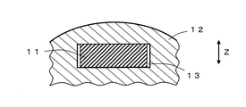
- FIG. 2A shows the state of the space filler 11 before expansion
- FIG. 2B shows the state of the space filler 11 after expansion
- the space filler 11 is inserted in the space 13 surrounded by the outer member 12.
- the space 13 is formed by being completely surrounded by a single outer member 12, but it does not have to be a closed space completely surrounded by the outer member, for example, a U-shape.
- an open space may be partially formed.
- the space may be formed by a plurality of different members.
- a plurality of space fillers 11 may be inserted in the space 13. Note that FIG. 2A shows a part of the outer member 12.
- thermoplastic resin By heating above the softening point of the thermoplastic resin constituting the space filler 11, the thermoplastic resin is softened, and accordingly, the curvature of the reinforcing fiber restrained by the thermoplastic resin is released, whereby the reinforcing fiber is released.
- Repulsive force (restoring force) is expressed in the thickness direction.
- the space filling material 11 irreversibly expands in the thickness direction (Z direction in FIG. 2A) and fills the space 13 as shown in FIG. 2B.
- a high pressing force is applied to the wall surface of the space 13 due to the expansion stress of the space filler 11, and at the same time, the molten thermoplastic resin is pressed against the outer member 12 and adheres to the outer member 12, so that the outer member 12 is sufficiently reinforced. Will be done.
- the heating temperature is not particularly limited unless there is a limitation on the heat resistance of the outer member or the material to be fixed.
- the softening point of the thermoplastic resin it may be (softening point +10) ° C. or higher, preferably (softening point +30) ° C. or higher, and more preferably (softening point +50) ° C. or higher. ..
- the upper limit of the heating temperature may be, for example, (softening point +250) ° C. or lower, preferably (softening point +200) ° C. or lower, and particularly from the viewpoint of suppressing deterioration of the thermoplastic resin, (softening point +150) ° C. or lower. Is more preferable.
- the space filler may expand rapidly, but may have a uniform structure as a whole by expanding slowly, for example, the heating time for expansion may be set, for example. It may be about 1 minute to 1 hour, preferably about 10 to 50 minutes.
- the method of using the space filler of the present invention may include a step of inserting the space filler into a predetermined space prior to the step of expanding the space filler.
- the thickness of the space to be inserted may be 1.01 to 4 times the average thickness of the space filler.
- the thickness may be preferably 1.2 to 3.5 times, more preferably 1.5 to 3 times.
- the porosity of the space filler after expansion may be 30 to 95%.
- the porosity of the expanded space-filling material is within this range, it is possible to sufficiently pass liquid and ventilate the expanded space-filling material.
- the porosity of the space filler after expansion may be preferably 35 to 90%, more preferably 40 to 85%.
- the porosity of the space filler after expansion is a value measured by the method described in Examples described later.
- the space filler after expansion may have a continuous porous structure.
- the voids of the expanded space-filling material are communication holes, it is possible to sufficiently pass liquid and ventilate the expanded space-filling material.
- the expansion rate after filling in the thickness direction may be 101 to 400%, preferably 120. It may be ⁇ 400%, more preferably 130-300%, still more preferably 140-250%.
- the expansion rate in the thickness direction is expressed by the following formula (3).
- Expansion rate after filling (%) Thickness of space filling material after filling (thickness of space to be filled) (mm) / Thickness of space filling material before filling (mm) x 100 (3)
- the ratio of the expansion rate after filling to the maximum expansion rate indicating the expansion capacity of the space filler is (expansion rate after filling-100) / (maximum).
- the expansion rate ⁇ 100) ⁇ 100 may be 1 to 90%, preferably 1.5 to 85%, and more preferably 2 to 83%.
- expansion can be used to obtain a desired size, and the thickness of a predetermined space (thickness of the space filler after expansion (after filling)) is as wide as, for example, 0.02 to 600 mm. It can be selected from the range, but from the viewpoint of filling a narrow gap, it may be, for example, 20 to 5000 ⁇ m, preferably 50 to 4000 ⁇ m, and more preferably 80 to 3000 ⁇ m.
- the CV value of the expanded thickness of the space filler may be 0.1 or less, preferably 0.08 or less, from the viewpoint of enabling the gap to be filled with high accuracy.
- the CV value of the thickness after expansion indicates the CV value of the thickness of the space filler after expansion under no pressure, and is a value measured by the method described in Examples described later. ..
- the punching load described in Examples described later may be 5N or more, preferably 10N or more, more preferably 15N or more, and further preferably 20N or more.
- the upper limit of the punching load is not particularly limited, but may be, for example, about 1000N.
- the punching load is a value measured by the method described in Examples described later. When the punching load in the above range is shown, it is useful as a reinforcing material or a fixing material because it has excellent strength to reinforce the space when filled in a predetermined space and to fix the material to be fixed.
- the method of using the space filler of the present invention may include a step of expanding the space filler in a predetermined space by heating at a softening point or higher of the thermoplastic resin to fix the material to be fixed. ..
- the space filler of the present invention may be used as a fixing material for fixing the material to be fixed.
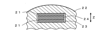
- FIG. 3A shows the state of the space filler 21 before expansion
- FIG. 3B shows the state of the space filler 21 after expansion.
- the fixed material 24 sandwiched between the two space filling materials 21 is inserted as the space filling structure 25 in the space 23 surrounded by the outer member 22.
- the space 23 is formed by being completely surrounded by a single outer member 22, but it does not have to be a closed space completely surrounded by the outer member, for example, a U-shape. As shown in the above, an open space may be partially formed.
- the space may be formed by a plurality of different members.
- the space filler 21 is laminated and inserted one by one on both sides of the fixed material 24, but the number of laminated materials and the insertion location are not limited, and one or one on at least one surface of the fixed material 24. A plurality of sheets may be stacked and inserted.
- the space fillers 21 laminated on both sides of the material to be fixed 24 may be the same or different, but are preferably the same from the viewpoint of enhancing the uniformity of expandability. Note that FIG. 3A shows a part of the outer member 22.
- thermoplastic resin By heating above the softening point of the thermoplastic resin constituting the space filler 21, the thermoplastic resin is softened, and accordingly, the curvature of the reinforcing fiber restrained by the thermoplastic resin is released, whereby the reinforcing fiber is released.
- Repulsive force (restoring force) is expressed in the thickness direction.
- the space filling material 21 irreversibly expands in the thickness direction (Z direction in FIG. 3A), and as shown in FIG. 3B, fills the space 23 together with the fixed material 24.
- a high pressing force is applied to the wall surface of the space 23 and both sides of the fixed material 24 due to the expansion stress of the space filling material 21, and at the same time, the molten thermoplastic resin is pressed against the wall surface of the space 23 and the fixed material 24 to adhere. By doing so, the material to be fixed 24 is sufficiently fixed.
- the method of using the space filler of the present invention may include a step of inserting the space filler and / or the fixed material into a predetermined space prior to the step of expanding and fixing the space filler. ..
- the space filler and the fixed material may be inserted together, or one of the space filler and the fixed material may be inserted first, and then the other may be inserted. Further, the space filler and the material to be fixed may be inserted into a predetermined space in which one is inserted in advance.
- the space-filling structure of the present invention may include a space-filling material and a fixed material that is in contact with and integrated with at least a part thereof.
- the space filling material and the material to be fixed may be integrated by fusion.
- the space-filling material and the material to be fixed are laminated so as to be in contact with each other, and the space-filling material is suppressed from expanding due to pressurization or the like at a temperature equal to or higher than the softening point of the thermoplastic resin in the space-filling material. By the heating method, the space-filling material and the material to be fixed can be fused and manufactured.
- the space-filling structure may be manufactured with reference to the method for manufacturing a space-filling material.
- the space-filling structure is laminated so that the composite sheet for forming the space-filling material and the material to be fixed are in contact with each other, and the space-filling structure is heated at a temperature equal to or higher than the softening point of the thermoplastic resin in the space-filling material.
- the space filler and the material to be fixed may be fused and manufactured by a method of pressurizing in the stacking direction and further cooling while pressurizing.
- the space-filling structure can be manufactured, for example, by laminating the space-filling material and the material to be fixed via an adhesive and adhering them to each other.
- the adhesive is not particularly limited as long as the space filler and the object to be fixed can be adhered, and a known adhesive can be used.
- the material to be fixed may be sandwiched by the space-filling material.
- the material to be fixed may be sandwiched by the space-filling material in at least two opposite directions, for example, may be sandwiched in the thickness direction of the material to be fixed, and is orthogonal to the thickness direction. It may be sandwiched in the direction.
- the direction orthogonal to the thickness direction is parallel to a predetermined side of the material to be fixed and orthogonal to the Z direction.
- the X direction see FIG. 3A
- the Y direction see FIG.
- the space-filling structure may be sandwiched in four directions composed of the Z direction which is the thickness direction of the material to be fixed and the X or Y direction, and is composed of the X direction, the Y direction, and the Z direction6. It may be sandwiched in the direction.
- the material to be fixed may be arranged in both directions facing the space filling material in each of the X direction, the Y direction, and the Z direction, or only in one of the directions.
- the material to be fixed may be arranged.
- the method of using the space-filling structure of the present invention may include a step of expanding the space-filling material in a predetermined space by heating at a softening point or higher of the thermoplastic resin to fix the material to be fixed. ..
- the method of using the space-filling structure of the present invention may include a step of inserting the space-filling structure into a predetermined space prior to the step of expanding and fixing the material to be fixed.
- the space-filling material of the present invention is a space-filling reinforcing material for filling a predetermined space surrounded by members in a means of transportation, a household appliance, an industrial machine, a building, etc. to reinforce the member, or the member. It can be effectively used as a space-filling fixing material for fixing the material to be fixed in a predetermined space surrounded by.
- the space filler has predetermined insulating properties and / or heat resistance
- one aspect of the space filler of the present invention can be usefully used as an insulating and / or heat resistant space filler.
- the space filling material and the space filling structure of the present invention are molds for fixing a permanent magnet (fixed material) in a plurality of holes formed in a rotor in a motor (for example, a motor for driving an automobile).
- the permanent magnet can be fixed with sufficient fixing strength, and the motor can be cooled by passing the cooling liquid through the voids existing as the communication holes, which imparts insulation. It is also possible to do. Further, since the fixing strength is high in spite of having voids, the ratio of the material occupying the space can be reduced, so that the cost can be reduced.
- Average fiber length The fiber lengths of 100 randomly selected fibers were measured, and the average value of the measured values was taken as the average fiber length.
- Average fiber diameter The fiber diameters of 30 randomly selected fibers were measured by microscopic observation, and the average value of the measured values was taken as the average fiber diameter.
- tensile elastic modulus The tensile elastic modulus was measured according to JIS R 3420 for glass fiber (hereinafter, may be abbreviated as GF) and JIS R 7606 for carbon fiber (hereinafter, may be abbreviated as CF).
- Glass transition temperature (Tg) of thermoplastic fiber For the glass transition temperature of the thermoplastic fiber, the temperature dependence of the loss tangent (tan ⁇ ) was measured at a frequency of 10 Hz and a heating rate of 10 ° C./min using a solid dynamic viscoelastic device “Leospectra DVE-V4” manufactured by Rheology. Then, it was obtained from the peak temperature.
- the peak temperature of tan ⁇ is the temperature at which the first derivative value of the amount of change of the value of tan ⁇ with respect to the temperature becomes zero.
- volume ratio The volume ratios of the reinforcing fibers and the thermoplastic resin constituting the space filler were calculated as the volume ratios (reinforcing fibers: thermoplastic resin) of each other by converting the weight ratios by the respective densities.
- Thickness CV value thickness standard deviation ( ⁇ m) / average thickness ( ⁇ m)
- the porosity (%) of the space filler was calculated in accordance with JIS K 7075 "Fiber content and porosity test of carbon fiber reinforced plastic".
- Image analysis conditions > Image analysis software: Aviso (manufactured by Thermo Fisher Scientific) After cutting the 3D image of the space filler sample obtained by X-ray CT measurement to 0.40 mm ⁇ 0.40 mm ⁇ total thickness on image analysis software, NON-LOCAL is required. Noise was removed by the Filter function. The NON-LOCAL Filter function was set under the following conditions. Spatial Standard Deviation Value: 5 Integrity Standard Deviation Value: 0.2 Search window value: 10 Local Neighborhood value: 3 Then, binarization was performed by the Interactive Thresholding function, and all the fibers were extracted.
- the Fiber Tracking function is used to meet the following setting conditions for the data obtained by cutting the image to a size of 0.40 mm ⁇ 0.40 mm ⁇ total thickness or the data from which noise has been removed by NON-LOCAL Filter processing. Fibers with diameter were extracted.
- Cylinder Correlation Cylinder lens value Any value between 2.5 and 3.5 times the fiber diameter
- Angular Sampleing value 5 Mask Cylinder Radius value: Arbitrary value between fiber radius +1 and fiber radius +13
- Outer Cylinder Radius value Fiber radius Inner Cylinder Radius value: 0
- the degree of tortuosity was defined as the "Tortuosity" of each extracted fiber.
- the volume content (vol%) of the reinforcing fibers having a degree of curvature of 1.004 or more with respect to the volume occupied by all the extracted reinforcing fibers was calculated. This was designated as "the ratio of the degree of curvature in the reinforcing fibers to 1.004 or more" in Table 1.
- the volume content of the total reinforced fiber with respect to the total volume of the space filler calculated in accordance with JIS K 7075 "Fiber content and cavity ratio test of carbon fiber reinforced plastic" has the degree of curvature with respect to the volume occupied by the total reinforced fiber.
- the volume content (vol%) of the reinforcing fibers having a degree of curvature of 1.004 or more with respect to the volume of the entire space filler was calculated. This was designated as "volume content of reinforcing fibers having a degree of curvature of 1.004 or more in the space filler" in Table 1.
- Average degree of curvature total degree of curvature of each extracted fiber / number of extracted fibers
- the thickness CV value of the expanded space filler was calculated by the same calculation method as the thickness CV value of the space filler described above.
- FIG. 4A is a schematic perspective view for explaining the preparation of a sample for a punching load test
- FIG. 4B is a schematic cross-sectional view for explaining the preparation of a sample for a punching load test.
- the space-filling material obtained in Examples and Comparative Examples was cut into a length of 50 mm and a width of 15 mm to prepare a space-filling material sample.
- a hollow square lumber (large) 32a having a length of 20 mm, a width of 20 mm, a thickness of 2.15 mm and a length of 100 mm and a hollow lumber (small) 32b having a width of 15 mm, a thickness of 1.5 mm and a length of 100 mm were prepared.
- the hollow square lumber (small) 32b is inserted into the hollow lumber (large) 32a, the gap between the inner side surface of the hollow square lumber (large) 32a and the outer side surface of the hollow square lumber (small) 32b becomes a predetermined height.
- Hollow lumber (small) 32b having a vertical dimension was prepared in each Example and Comparative Example.
- the vertical dimension of the hollow square lumber (small) 32b was adjusted to be (inner vertical dimension (15.7 mm) of the hollow square lumber (large) 32a-gap height h ⁇ 2).
- the hollow lumber (large) 32a A blower constant temperature incubator (Yamato Scientific Co., Ltd.) in which one space-filling material sample 31 is inserted into each of the two gaps between the inner side surface and the outer side surface of the hollow square lumber (small) 32b and set to a predetermined temperature.
- the space filler sample 31 was filled by putting it in the product "DN411H"), heating it for 20 minutes, taking it out, and cooling it to 25 ° C.
- the porosity (%) of the space-filling material after being completely filled was calculated by the same calculation method as the porosity of the space-filling material described above, and used as the porosity after filling.
- a universal tester (“AG-2000A” manufactured by Shimadzu Corporation) is used to apply a load to the obtained punching load test sample only in the hollow square lumber (small) at a compression speed of 2 mm / min in the length direction. , The hollow square lumber (small) was punched out, and the load at the time when the displacement started to occur was defined as the punching load (N).
- PEI polyetherimide
- ULTEM9001 manufactured by Servic Innovative Plastics
- the PEI-based polymer was discharged from a round hole nozzle under the conditions of a spinning head temperature of 390 ° C., a spinning speed of 1500 m / min, and a discharge rate of 50 g / min to prepare a multifilament of 2640 dtex / 1200 f PEI fiber.
- the obtained multifilament was cut to 15 mm to prepare a shortcut fiber of PEI fiber.
- the appearance of the obtained fiber is good without fluff, the single fiber fineness is 2.2 dtex, the average fiber length is 15.0 mm, and the glass transition temperature (softening point in the amorphous thermoplastic resin) is 217 ° C.
- the density was 1.27 g / cm 3 .
- the obtained PET-based polymer is supplied to a vent-type twin-screw extruder heated at 270 ° C. and guided to a spinning head heated to 280 ° C. after a residence time of 2 minutes, and a discharge rate of 45 g / g /
- a multifilament made of a PET-based polymer of 2640 dtex / 1200 f was produced by discharging from a round hole nozzle under the condition of minutes and taking up at a spinning speed of 1200 m / min. The resulting fiber was then cut to 5 mm.
- the appearance of the obtained fibers was good without fluff and the like, the single fiber fineness was 2.2 dtex, the average fiber length was 5.0 mm, and the density was 1.38 g / cm 3 .
- PC polycarbonate
- Iupilon S-3000 Mitsubishi Engineering Plastics “Iupilon S-3000”
- the PC-based polymer was discharged from a round hole nozzle under the conditions of a spinning head temperature of 300 ° C., a spinning speed of 1500 m / min, and a discharge rate of 50 g / min to prepare a multifilament of PC fibers having 2640 dtex / 1200 f.
- the obtained multifilament was cut to 15 mm to prepare a shortcut fiber of PC fiber.
- the appearance of the obtained fiber is good without fluff, the single fiber fineness is 2.2 dtex, the average fiber length is 15.0 mm, and the glass transition temperature (softening point in the amorphous thermoplastic resin) is 150 ° C.
- the specific gravity was 1.2 g / cm 3 .
- Example 1 50 wt% of PEI fiber as a thermoplastic fiber, 45 wt% of a glass fiber with a cut length of 13 mm as a reinforcing fiber (manufactured by Nippon Electric Glass: average fiber diameter 10.5 ⁇ m, specific gravity 2.54 g / cm 3 ), and PET-based binder as a binder fiber. 5 wt% of the fiber was put into 1.5 L of water and 40 mL of the dispersant, and stirred 1500 times at 540 rpm using a disintegrator to prepare a slurry.
- a mixed nonwoven fabric (mixed paper) having a basis weight of 78 g / m 2 was obtained by a wet raid process.
- Three layers of the obtained mixed non-woven fabric were laminated, and using a test press machine (“KVHC-II” manufactured by Kitagawa Seiki Co., Ltd.), 10 at 340 ° C. while pressurizing the surface perpendicular to the laminating direction at 3 MPa.
- the space filler After heating for a minute and impregnating the melted PEI-based polymer and PET-based polymer between the glass fibers, the space filler is cooled to 150 ° C., which is below the glass transition temperature of the PEI-based polymer, while maintaining the pressure.
- the average thickness of the obtained space filler was 144 ⁇ m, the thickness CV value was 0.049, the average grain size was 233.8 g / m 2 , the grain size CV value was 0.024, the density was 1.625 g / cm 3 , and the voids.
- the ratio was 1.4%, and the volume content of the reinforcing fibers having a degree of curvature of 1.004 or more with respect to the total volume of the reinforcing fibers was 82.7 vol%.
- Various evaluations were performed on the obtained space filler, and the evaluation results are shown in Table 1.
- the set temperature of the blower constant temperature incubator in the expansiveness evaluation is 260 ° C.
- the set temperature of the blower constant temperature incubator at the time of preparing the sample for punching load test is 280 ° C.
- the gap height h of the sample for punching load test is 300 ⁇ m. And said.
- Example 2 In the process of producing the space filler, the space filler was produced in the same manner as in Example 1 except that the number of mixed nonwoven fabrics was one.
- the average thickness of the obtained space filler is 63 ⁇ m, the thickness CV value is 0.060, the average grain size is 81.2 g / m 2 , the grain size CV value is 0.024, the density is 1.293 g / cm 3 , and the voids.
- the ratio was 21.5%, and the volume content of the reinforcing fibers having a degree of curvature of 1.004 or more with respect to the total volume of the reinforcing fibers was 81.5 vol%.
- the obtained space filler was evaluated in the same manner as in Example 1 except that the gap height h of the punching load test sample was changed to 100 ⁇ m, and the evaluation results are shown in Table 1.
- Example 3 A mixed nonwoven fabric was produced in the same manner as in Example 1 except that the thickener and the dispersant were not added in the mixed nonwoven fabric manufacturing step. Then, in the process of producing the space filler, the space filler was produced in the same manner as in Example 2. The average thickness of the obtained space filler is 82 ⁇ m, the thickness CV value is 0.230, the average grain size is 77.4 g / m 2 , the grain size CV value is 0.045, the density is 0.942 g / cm 3 , and the voids.
- the ratio was 42.8%, and the volume content of the reinforcing fibers having a degree of curvature of 1.004 or more with respect to the total volume of the reinforcing fibers was 76.1 vol%.
- the obtained space filler was evaluated in the same manner as in Example 2, and the evaluation results are shown in Table 1.
- Example 4 In the process of producing the space filler, the space filler was produced in the same manner as in Example 1 except that the number of mixed nonwoven fabrics was 30.
- the average thickness of the obtained space filler is 1500 ⁇ m, the thickness CV value is 0.021, the average grain size is 2400 g / m 2 , the grain size CV value is 0.018, the density is 1.600 g / cm 3 , and the porosity is.
- the volume content of the reinforcing fibers having a degree of curvature of 1.004 or more with respect to the total volume of the reinforcing fibers was 83.2 vol%.
- the obtained space filler was evaluated in the same manner as in Example 1 except that the gap height h of the punching load test sample was changed to 3000 ⁇ m, and the evaluation results are shown in Table 1.
- Example 5 A space filler was prepared in the same manner as in Example 2 except that a glass fiber having a cut length of 13 mm (manufactured by Nippon Electric Glass: average fiber diameter 6.5 ⁇ m, specific density 2.54 g / cm 3 ) was used as the reinforcing fiber. ..
- the average thickness of the obtained space filler is 62 ⁇ m, the thickness CV value is 0.038, the average grain size is 81.0 g / m 2 , the grain size CV value is 0.024, the density is 1.306 g / cm 3 , and the voids.
- the ratio was 20.7%, and the volume content of the reinforcing fibers having a degree of curvature of 1.004 or more with respect to the total volume of the reinforcing fibers was 83.0 vol%.
- the obtained space filler was evaluated in the same manner as in Example 2, and the evaluation results are shown in Table 1.
- Example 6 A space filler was prepared in the same manner as in Example 2 except that a glass fiber having a cut length of 13 mm (manufactured by Nippon Electric Glass: average fiber diameter 13 ⁇ m, specific density 2.54 g / cm 3 ) was used as the reinforcing fiber.
- the average thickness of the obtained space filler is 68 ⁇ m, the thickness CV value is 0.059, the average grain size is 79.5 g / m 2 , the grain size CV value is 0.031, the density is 1.169 g / cm 3 , and the voids.
- the ratio was 29.0%, and the volume content of the reinforcing fibers having a degree of curvature of 1.004 or more with respect to the total volume of the reinforcing fibers was 81.0 vol%.
- the obtained space filler was evaluated in the same manner as in Example 2, and the evaluation results are shown in Table 1.
- Example 7 In the mixed non-woven fabric manufacturing process, PEI fiber 75 wt% as thermoplastic fiber, glass fiber with a cut length of 13 mm as reinforcing fiber (manufactured by Nippon Denki Glass: average fiber diameter 10.5 ⁇ m, specific gravity 2.54 g / cm 3 ) 15 wt%, and A space filler was prepared in the same manner as in Example 1 except that a slurry was prepared using 5 wt% of PET-based binder fiber as the binder fiber.
- the average thickness of the obtained space filler was 145 ⁇ m, the thickness CV value was 0.035, the average grain size was 203.6 g / m 2 , the grain size CV value was 0.031, the density was 1.404 g / cm 3 , and the voids.
- the ratio was 0.8%, and the volume content of the reinforcing fibers having a degree of curvature of 1.004 or more with respect to the total volume of the reinforcing fibers was 72.0 vol%.
- the obtained space filler was evaluated in the same manner as in Example 1, and the evaluation results are shown in Table 1.
- Example 8 In the process of producing the space filler, the space filler was produced in the same manner as in Example 1 except that a spacer having a thickness of 0.3 mm was arranged during hot pressing.
- the average thickness of the obtained space filler is 295 ⁇ m
- the thickness CV value is 0.020
- the average grain size is 245.0 g / m 2
- the grain size CV value is 0.020
- the density is 0.831 g / cm 3
- the ratio was 49.5%
- the volume content of the reinforcing fibers having a degree of curvature of 1.004 or more with respect to the total volume of the reinforcing fibers was 38.0 vol%.
- the obtained space filler was evaluated in the same manner as in Example 1, and the evaluation results are shown in Table 1.
- Example 9 In the mixed non-woven fabric manufacturing process, 55 wt% of PEI fiber as thermoplastic fiber, 40 wt% of carbon fiber with a cut length of 13 mm as reinforcing fiber (manufactured by Toho Tenax: average fiber diameter 7 ⁇ m, specific gravity 1.82 g / cm 3 ), and as binder fiber. A space filler was prepared in the same manner as in Example 1 except that the slurry was prepared using 5 wt% of PET-based binder fiber.
- the average thickness of the obtained space filler is 165 ⁇ m, the thickness CV value is 0.052, the average grain size is 235.0 g / m 2 , the grain size CV value is 0.025, the density is 1.424 g / cm 3 , and the voids.
- the ratio was 1.9%, and the volume content of the reinforcing fibers having a degree of curvature of 1.004 or more with respect to the total volume of the reinforcing fibers was 83.1 vol%.
- the obtained space filler was evaluated in the same manner as in Example 1, and the evaluation results are shown in Table 1.
- Example 10 A mixed nonwoven fabric was produced in the same manner as in Example 1 except that PC fibers were used as the thermoplastic fibers in the mixed nonwoven fabric manufacturing process. Three layers of the obtained mixed non-woven fabric were laminated, and using a test press machine (“KVHC-II” manufactured by Kitagawa Seiki Co., Ltd.), 10 at 280 ° C. while pressurizing the surface perpendicular to the laminating direction at 3 MPa. After heating for a minute and impregnating the molten PC-based polymer and PET-based polymer between the glass fibers, the space filler is cooled to 130 ° C., which is below the glass transition temperature of the PC-based polymer, while maintaining the pressure. Was produced.
- KVHC-II manufactured by Kitagawa Seiki Co., Ltd.
- the average thickness of the obtained space filler is 142 ⁇ m, the thickness CV value is 0.045, the average grain size is 221.0 g / m 2 , the grain size CV value is 0.023, the density is 1.556 g / cm 3 , and the voids.
- the ratio was 1.9%, and the volume content of the reinforcing fibers having a degree of curvature of 1.004 or more with respect to the total volume of the reinforcing fibers was 79.1 vol%.
- the set temperature of the blower constant temperature incubator in the expansiveness evaluation was 190 ° C, and the set temperature of the blower constant temperature incubator at the time of preparing the sample for the punching load test was 210 ° C. The evaluation was performed in the same manner, and the evaluation results are shown in Table 1.
- Example 1 In the process of producing the space filler, the space filler was produced in the same manner as in Example 1 except that a spacer having a thickness of 0.5 mm was arranged during hot pressing.
- the average thickness of the obtained space filler was 514 ⁇ m
- the thickness CV value was 0.088
- the average grain size was 231.0 g / m 2
- the grain size CV value was 0.030
- the density was 0.449 g / cm 3
- the ratio was 72.7%
- the volume content of the reinforcing fibers having a degree of curvature of 1.004 or more with respect to the total volume of the reinforcing fibers was 13.9 vol%.
- the obtained space filler was evaluated in the same manner as in Example 1 except that the gap height h of the punching load test sample was changed to 600 ⁇ m, and the evaluation results are shown in Table 1.
- the space filler was prepared in the same manner as in Example 1 except that the cooling was performed without maintaining the pressurization when moving to the cooling process after the melting step at the time of hot pressing. Made.
- the average thickness of the obtained space filler was 485 ⁇ m, the thickness CV value was 0.075, the average basis weight was 232.0 g / m 2 , the basis weight CV value was 0.031, the density was 0.478 g / cm 3 , and the voids.
- the rate was 71.0%.
- the obtained space filler was evaluated in the same manner as in Example 1 except that the gap height h of the punching load test sample was changed to 600 ⁇ m, and the evaluation results are shown in Table 1.
- a spacer with a thickness of 70 ⁇ m was placed on the obtained mixed non-woven fabric, and the mixture was added at 1 MPa to the surface perpendicular to the laminating direction. While pressing, it is heated at 340 ° C. for 10 minutes, impregnated with the melted PEI resin between the glass fibers, and then cooled to 150 ° C., which is below the glass transition temperature of PEI, while maintaining the pressure, and the space filler is used. Was produced.
- the average thickness of the obtained space filler is 60 ⁇ m, the thickness CV value is 0.021, the average grain size is 80.0 g / m 2 , the grain size CV value is 0.021, the density is 1.333 g / cm 3 , and the voids.
- the ratio was 0.7%, and the volume content of the reinforcing fibers having a degree of curvature of 1.004 or more with respect to the total volume of the reinforcing fibers was 18.0 vol%.
- the obtained space filler was evaluated in the same manner as in Example 2, and the evaluation results are shown in Table 1.
- the space fillers of Examples 1 to 10 have excellent expandability because a specific amount of reinforcing fibers having a degree of curvature of 1.004 or more is present, and the strength (pushing load) for reinforcing or fixing is high. It can be seen that it is high at 5N or more. It should be noted that, as a method of using the space filler, it is possible to exert a higher expansion stress by filling the gap with an expansion rate relatively low with respect to the maximum expansion rate indicating the expansion capacity of the space filler. In Example 8, it is considered that the space filler having a maximum expansion rate of 194% is used as the expansion rate of 102% after filling, so that the punching load is 231N, which is a very high fixing strength. Further, since the space fillers of Examples 1, 2 and 4 to 6 have a very small thickness CV value of 0.2 or less, the thickness CV value after expansion is 0.1 or less, and the gap is accurate. It can be filled well.
- Comparative Examples 1 to 3 since the abundance of the reinforcing fibers having a degree of curvature of 1.004 or more is less than 20 vol%, the fibers hardly expand and the strength (pushing load) for reinforcing or fixing is very low.
- the space filling material of the present invention is useful for filling a predetermined space surrounded by members in transportation means, home appliances, industrial machines, buildings, and the like.
- the space filling material can be used as a reinforcing material for reinforcing the member or as a fixing material for fixing the fixed material in a predetermined space surrounded by the member.
- the space filler of the present invention can be used as a mold material for fixing a permanent magnet (fixed material) in a plurality of holes formed in a rotor in a motor (for example, a motor for driving an automobile). can.
Landscapes
- Chemical & Material Sciences (AREA)
- Engineering & Computer Science (AREA)
- Textile Engineering (AREA)
- Chemical Kinetics & Catalysis (AREA)
- Inorganic Chemistry (AREA)
- Health & Medical Sciences (AREA)
- Medicinal Chemistry (AREA)
- Manufacturing & Machinery (AREA)
- Materials Engineering (AREA)
- Polymers & Plastics (AREA)
- Organic Chemistry (AREA)
- Combustion & Propulsion (AREA)
- Mechanical Engineering (AREA)
- General Engineering & Computer Science (AREA)
- Toxicology (AREA)
- Reinforced Plastic Materials (AREA)
- Laminated Bodies (AREA)
Abstract
Description
〔態様1〕
強化繊維と熱可塑性樹脂とで構成され、前記強化繊維同士が複数の交点を有し、少なくともその交点の一部が熱可塑性樹脂で接着される空間充填材であり、前記強化繊維全体の体積に対する、下記式(1)で規定される湾曲度が1.004以上の強化繊維の体積含有率が20vol%以上(好ましくは30vol%以上、より好ましくは35vol%以上、さらに好ましくは40vol%以上)である、空間充填材。
湾曲度=繊維長/繊維両端の最短距離 (1)
〔態様2〕
態様1に記載の空間充填材であって、厚さのCV値が0.2以下(好ましくは0.1以下、より好ましくは0.08以下、さらに好ましくは0.06以下)である、空間充填材。
〔態様3〕
態様1または2に記載の空間充填材であって、平均厚さが10~1000μm(好ましくは20~500μm、より好ましくは50~300μm)である、空間充填材。
〔態様4〕
態様1~3のいずれか一態様に記載の空間充填材であって、下記式(2)で規定される湾曲度の解放率が20%以上(好ましくは30%以上、より好ましくは40%以上、さらに好ましくは50%以上、さらにより好ましくは60%以上)である、空間充填材。
湾曲度の解放率(%)=
[(X-1)-(Y-1)]/(X-1)×100 (2)
(式中、X:膨張前空間充填材中の強化繊維の平均湾曲度、Y:無加圧下で加熱膨張させた後の空間充填材中の強化繊維の平均湾曲度)
〔態様5〕
態様1~4のいずれか一態様に記載の空間充填材であって、目付のCV値が0.2以下(好ましくは0.15以下、より好ましくは0.1以下)である、空間充填材。
〔態様6〕
態様1~5のいずれか一態様に記載の空間充填材であって、前記強化繊維の平均繊維長が3~100mm(好ましくは4~80mm、より好ましくは5~50mm)である、空間充填材。
〔態様7〕
態様1~6のいずれか一態様に記載の空間充填材であって、空間充填材全体の体積に対する、湾曲度が1.004以上の強化繊維の体積含有率が3~50vol%(好ましくは5~45vol%、より好ましくは10~40vol%)である、空間充填材。
〔態様8〕
態様1~7のいずれか一態様に記載の空間充填材であって、空間充填材全重量に対する、熱可塑性樹脂の重量含有率が40~85wt%(好ましくは45~82wt%、より好ましくは50~80wt%、さらに好ましくは52~75wt%)である、空間充填材。
〔態様9〕
態様1~8のいずれか一態様に記載の空間充填材と、その少なくとも一部に接して一体化された被固定材とを備える、空間充填構造体。
〔態様10〕
態様1~8のいずれか一態様に記載の空間充填材を製造する方法であって、
強化繊維と熱可塑性樹脂とを含む複合シートを準備する工程と、
前記複合シートを前記熱可塑性樹脂の軟化点以上に加熱し、厚み方向に圧力をかけて熱プレスする工程と、
圧力をかけたまま、前記熱可塑性樹脂の軟化点より低い温度まで冷却する工程と、
を少なくとも備える、空間充填材の製造方法。
〔態様11〕
態様10に記載の製造方法であって、前記複合シートが、強化繊維と熱可塑性繊維とを含む混抄紙である、空間充填材の製造方法。
〔態様12〕
態様11に記載の製造方法であって、前記混抄紙が、強化繊維、熱可塑性繊維および分散剤を含む水性スラリーから形成されている、空間充填材の製造方法。
〔態様13〕
態様12に記載の製造方法であって、前記水性スラリーがさらに増粘剤を含む、空間充填材の製造方法。
本発明の空間充填材の製造方法は、強化繊維と熱可塑性樹脂とを含む複合シートを準備する工程と、前記複合シートを前記熱可塑性樹脂の軟化点以上に加熱し、厚み方向に圧力をかけて熱プレスする工程と、圧力をかけたまま、前記熱可塑性樹脂の軟化点より低い温度まで冷却する工程と、を少なくとも備えていてもよい。特定の湾曲度を有する強化繊維が特定量存在する空間充填材を製造するためには、所望の空間充填材の目付や厚さ等に応じて後述の製造条件を適宜調整する必要があるが、例えば、複合シート中の強化繊維の割合や熱プレスに供する複合シートの枚数、熱プレスの条件等を調整することにより強化繊維の湾曲度を調整することが可能である。
これらのうち、強化繊維の反発力を高くする観点から、ガラス繊維または炭素繊維などの高弾性率の無機繊維を用いるのが好ましい。また、膨張後の空間充填材を含む構造体において絶縁性が要求される用途の場合、絶縁性繊維(例えば、ガラス繊維、窒化ケイ素繊維、シリカ繊維、アルミナ繊維など)であってもよい。
また、ポリエステル系樹脂を構成するジオール成分としては、エチレングリコールをジオール成分として用いることができるが、エチレングリコール以外の少量(例えば、5モル%以下)の他のジオール成分を、一種または複数種類組み合わせて含んでもよい。
本発明の空間充填材は、強化繊維と熱可塑性樹脂とで構成されている。空間充填材は、本発明の効果を損なわない限り、強化繊維および熱可塑性樹脂以外の物質を含んでいてもよい。前記強化繊維同士が複数の交点を有し、少なくともその交点の一部が熱可塑性樹脂で接着されている。例えば、強化繊維同士は、ランダムに配向した状態で複数の交点を有し、少なくとも強化繊維の交点の一部が熱可塑性樹脂により接着されていてもよく、好ましくは、強化繊維同士の交点を中心として熱可塑性樹脂が水掻き状に存在していてもよく、強化繊維がマトリクスを形成する熱可塑性樹脂中に埋入されていてもよい。このような構造を取る事で、空間充填材の構造強度が向上する。
湾曲度=繊維長/繊維両端の最短距離 (1)
湾曲度の解放率(%)=
[(X-1)-(Y-1)]/(X-1)×100 (2)
(式中、X:膨張前空間充填材中の強化繊維の平均湾曲度、Y:無加圧下で加熱膨張させた後の空間充填材中の強化繊維の平均湾曲度を表す。)
本発明の空間充填材の使用方法は、熱可塑性樹脂の軟化点以上で加熱することにより所定の空間内で空間充填材を膨張させる工程を含んでいてもよい。本発明において、所定の空間とは、単一の外方部材に囲まれる空間(隙間)であってもよく、複数の外方部材で形成される空間(隙間)であってもよい。また、空間充填材は、所定の空間を全て充填してもよいし、一部を充填してもよい。
充填後膨張率(%)=充填後の空間充填材の厚さ(充填する空間の厚さ)(mm)/充填前の空間充填材の厚さ(mm)×100 (3)
本発明の空間充填構造体は、空間充填材と、その少なくとも一部に接して一体化した被固定材とを備えていてもよい。
空間充填構造体は、例えば、前記空間充填材と被固定材とを融着により一体化してもよい。例えば、前記空間充填材と被固定材とが接するように積層し、加圧などにより空間充填材が膨張するのを抑制しつつ、空間充填材中の前記熱可塑性樹脂の軟化点以上の温度で加熱する方法により、前記空間充填材と被固定材とを融着させて製造することができる。
または、空間充填構造体は、空間充填材の製造方法を参照して製造してもよい。例えば、空間充填構造体は、空間充填材を形成するための複合シートと被固定材とが接するように積層し、空間充填材中の前記熱可塑性樹脂の軟化点以上の温度で加熱しつつ、積層方向に加圧し、さらに、加圧しながら冷却する方法により、前記空間充填材と被固定材とを融着させて製造してもよい。
または、空間充填構造体は、例えば、空間充填材と被固定材とを接着剤を介して積層して、接着させて製造することができる。この場合、接着剤としては、空間充填材と被固定材とを接着させることができる限り特に限定されず、公知の接着剤を使用することができる。
本発明の空間充填構造体の使用方法は、熱可塑性樹脂の軟化点以上で加熱することにより所定の空間において前記空間充填材を膨張させて、被固定材を固定する工程を含んでいてもよい。
特に、空間充填材が所定の絶縁特性および/または耐熱性を有する場合、本発明の空間充填材の一態様では、絶縁性および/または耐熱性空間充填材として有用に用いることができる。
JIS L 1015:2010「化学繊維ステープル試験方法」の8.5.1のB法に準じて、後述の方法で算出した平均繊維長を用いて、単繊維繊度を測定した。
ランダムに選択した100本の繊維について、その繊維長を測定し、その測定値の平均値を平均繊維長とした。
ランダムに選択した30本の繊維について、顕微鏡観察により繊維径を測定し、その測定値の平均値を平均繊維径とした。
ガラス繊維(以下、GFと略称することがある)の場合はJIS R 3420、炭素繊維(以下、CFと略称することがある)の場合はJIS R 7606に準拠し、引張弾性率を測定した。
熱可塑性繊維のガラス転移温度は、レオロジー社製固体動的粘弾性装置「レオスペクトラDVE-V4」を用い、周波数10Hz、昇温速度10℃/minで損失正接(tanδ)の温度依存性を測定し、そのピーク温度から求めた。ここで、tanδのピーク温度とは、tanδの値の温度に対する変化量の第1次微分値がゼロとなる温度のことである。
空間充填材を構成する強化繊維および熱可塑性樹脂の体積比率は、重量比率を、それぞれの密度により換算して、互いの体積比(強化繊維:熱可塑性樹脂)として算出した。
縦250mm、横250mmの空間充填材サンプルを、縦50mm、横15mmの小片80個に切り出し、全ての小片の重量(g)を計測し、目付(g/m2)を算出し、全小片の目付の平均値を空間充填材の平均目付(g/m2)とした。また、全小片の目付の標準偏差を算出し、以下の式より目付のCV値を算出した。
目付CV値=目付標準偏差(g/m2)/平均目付(g/m2)
縦250mm、横250mmの空間充填材サンプルを、縦50mm、横15mmの小片80個に切り出し、各小片の中央の厚さ(μm)をマイクロメータで計測し、全小片の厚さの平均値を空間充填材の平均厚さ(μm)とした。また、全小片の厚さの標準偏差を算出し、以下の式より厚さのCV値を算出した。
厚さCV値=厚さ標準偏差(μm)/平均厚さ(μm)
密度は、空間充填材サンプルを縦50mm、横15mmに切り出し、その厚さ(cm)と重量(g)を計測し、下記式により算出した。
密度(g/cm3)=重量(g)/(厚さ(cm)×7.5(cm2))
JIS K 7075「炭素繊維強化プラスチックの繊維含有率及び空洞率試験」に準拠し、空間充填材の空隙率(%)を算出した。
空間充填材サンプルを縦50mm、横15mmに切り出し、下記条件でX線CT測定して得られた画像を下記の手順で画像解析することにより湾曲度を測定した。
<X線CT測定条件>
測定装置:Xradia 520 Versa(カールツァイス社製)
X線ターゲット:タングステン
X線管電圧:100kV
出力:9W
対物レンズ:4X
ピクセルサイズ:1μm/pix
ビニング:1
撮像枚数:3201枚
露光時間:6秒/枚
画像解析ソフト:Avizo(サーモフィッシャーサイエンティフィック社製)
X線CT測定により得られた空間充填材サンプルの3次元画像を画像解析ソフトウェア上で、0.40mm×0.40mm×全厚さになるよう画像をカットした後、必要に応じてNON-LOCAL Filter機能によりノイズを除去した。NON-LOCAL Filter機能は以下の条件に設定した。
Spatial Standard Deviation値:5
Intensity Standard Deviation値:0.2
Search window値:10
Local Neighborhood値:3
そして、Interactive Thresholding機能で二値化を行い、全ての繊維を抽出した。
Cylinder CorrelationのCylinder length値:繊維直径の2.5~3.5倍の間の任意の値
Angular Sampling値:5
Mask Cylinder Radius値:繊維半径+1~繊維半径+13の間の任意の値
Outer Cylinder Radius値:繊維半径
Inner Cylinder Radius値:0
Trace Correlation LinesのDirection Coefficient値:0.1~0.5
Minimum Distance値:繊維半径~繊維直径の間の任意の値
平均湾曲度=抽出した各繊維の湾曲度の合計/抽出した繊維本数
実施例および比較例にて得られた空間充填材を、熱可塑性樹脂の軟化点以上の所定の温度に設定した送風定温恒温器(ヤマト科学株式会社製「DN411H」)中に入れて10分加熱後、取り出して25℃まで冷却した。その後、膨張後のサンプルの平均厚さを測定し、加熱前後のサンプルの平均厚さより、下記式を用いて最大膨張率(%)を測定した。
最大膨張率(%)=膨張後の空間充填材の平均厚さ(μm)/膨張前の空間充填材の平均厚さ(μm)×100
湾曲度の解放率(%)=
[(X-1)-(Y-1)]/(X-1)×100
(式中、X:膨張前空間充填材中の強化繊維の平均湾曲度、Y:無加圧下で加熱膨張させた後の空間充填材中の強化繊維の平均湾曲度)
押抜荷重試験用サンプルは下記手順にて作製した。図4Aは押抜荷重試験用サンプルの作製を説明するための概略斜視図であり、図4Bは、押抜荷重試験用サンプルの作製を説明するための概略断面図である。
(1)実施例および比較例で得られた空間充填材を、長さ50mm、幅15mmに切り出し、空間充填材サンプルを作製した。
(2)縦20mm、横20mm、厚さ2.15mm、長さ100mmの中空角材(大)32aと、横15mm、厚さ1.5mm、長さ100mmの中空角材(小)32bを準備した。ここで、中空角材(大)32aに中空角材(小)32bを挿入した時に、中空角材(大)32aの内側横面と中空角材(小)32bの外側横面との隙間が所定の高さとなる縦寸法を有する中空角材(小)32bを、各実施例および比較例で準備した。すなわち、中空角材(小)32bの縦寸法は、(中空角材(大)32aの内側縦寸法(15.7mm)-隙間高さh×2)となるように調整した。
(3)図4Aに示すように、中空角材(大)32aの中に中空角材(小)32bを長さ方向に50mm挿入した状態で、図4Bに示すように、中空角材(大)32aの内側横面と中空角材(小)32bの外側横面との隙間の2か所にそれぞれ空間充填材サンプル31を1枚ずつ挿入し、所定の温度に設定した送風定温恒温器(ヤマト科学株式会社製「DN411H」)中に入れて20分加熱後、取り出して25℃まで冷却することで、空間充填材サンプル31を充填した。
充填後膨張率(%)=充填後の空間充填材の平均厚さ(μm)/充填前の空間充填材の平均厚さ(μm)×100
非晶性樹脂であるポリエーテルイミド(以下、PEIと略称することがある)系ポリマー(サービックイノベイティブプラスチックス製「ULTEM9001」)を150℃で12時間真空乾燥した。前記PEI系ポリマーを紡糸ヘッド温度390℃、紡糸速度1500m/min、吐出量50g/minの条件で丸孔ノズルより吐出し、2640dtex/1200fのPEI繊維のマルチフィラメントを作製した。得られたマルチフィラメントを15mmにカットし、PEI繊維のショートカットファイバーを作製した。得られた繊維の外観は毛羽等なく良好で、単繊維繊度は2.2dtex、平均繊維長は15.0mmであり、ガラス転移温度(非晶性熱可塑性樹脂における軟化点)は217℃であり、密度は1.27g/cm3であった。
重合反応装置を用い、常法により280℃で重縮合反応を行い、ジカルボン酸成分としてテレフタル酸とイソフタル酸の共重合割合(モル比)が70/30、ジオール成分としてエチレングリコール100モル%からなる、固有粘度(η)が0.81であるPET系ポリマーを製造した。得られたポリマーを、重合装置底部よりストランド状に水中に押し出し、ペレット状に切断した。得られたPET系ポリマーを、270℃で加熱された同方向回転タイプのベント式2軸押し出し機に供給し、滞留時間2分を経て280℃に加熱された紡糸ヘッドに導き、吐出量45g/分の条件で丸孔ノズルより吐出し、紡糸速度1200m/分で引き取ることで2640dtex/1200fのPET系ポリマーからなるマルチフィラメントを作製した。次いで得られた繊維を5mmにカットした。得られた繊維の外観は毛羽等なく良好で、単繊維繊度は2.2dtex、平均繊維長は5.0mm、密度は1.38g/cm3であった。
非晶性樹脂であるポリカーボネート(以下、PCと略称することがある)系ポリマー(三菱エンジニアリングプラスチック製「ユーピロンS-3000」)を120℃で6時間真空乾燥した。前記PC系ポリマーを紡糸ヘッド温度300℃、紡糸速度1500m/min、吐出量50g/minの条件で丸孔ノズルより吐出し、2640dtex/1200fのPC繊維のマルチフィラメントを作製した。得られたマルチフィラメントを15mmにカットし、PC繊維のショートカットファイバーを作製した。得られた繊維の外観は毛羽等なく良好で、単繊維繊度は2.2dtex、平均繊維長は15.0mmであり、ガラス転移温度(非晶性熱可塑性樹脂における軟化点)は150℃であり、比重は1.2g/cm3であった。
パムオール(明成化学工業製)2gを水2Lに添加し、完全に溶解するまで攪拌する事で、増粘剤を調製した。
アルコックスCP-B1(明成化学工業製)3.75gを2Lの水に溶解させたものと、パルセットHA(明成化学工業製)3.75gを2Lの水に溶解させたものを分散剤としてそれぞれ調製した。各分散剤を20mLずつスラリーに添加して使用した。
熱可塑性繊維としてPEI繊維50wt%、強化繊維として13mmのカット長のガラス繊維(日本電気硝子製:平均繊維径10.5μm、比重2.54g/cm3)45wt%、およびバインダー繊維としてPET系バインダー繊維5wt%を、水1.5L、分散剤40mL中に投入し、離解機を用いて540rpmで1500回攪拌し、スラリーを調製した。得られたスラリーに増粘剤60~80mLを加え、ウェットレイドプロセスにより目付78g/m2の混合不織布(混抄紙)を得た。
得られた混合不織布を3枚積層し、テストプレス機(北川精機製「KVHC-II」)を用いて、積層方向に対して垂直な面に対して3MPaにて加圧しながら、340℃で10分間加熱し、ガラス繊維の間に溶融したPEI系ポリマー及びPET系ポリマーを含浸させた後、加圧を維持したまま、PEI系ポリマーのガラス転移温度以下である150℃まで冷却し、空間充填材を作製した。得られた空間充填材の平均厚さは144μm、厚さCV値は0.049、平均目付は233.8g/m2、目付CV値は0.024、密度は1.625g/cm3、空隙率は1.4%、強化繊維全体の体積に対する湾曲度が1.004以上の強化繊維の体積含有率は82.7vol%であった。
得られた空間充填材について、各種評価を行い、評価結果を表1に示す。なお、膨張性評価における送風定温恒温器の設定温度は260℃、押抜荷重試験用サンプル作製時の送風定温恒温器の設定温度は280℃、押抜荷重試験用サンプルの隙間高さhを300μmとした。
空間充填材の作製工程にて、混合不織布の枚数を1枚としたこと以外は実施例1と同様にして、空間充填材を作製した。得られた空間充填材の平均厚さは63μm、厚さCV値は0.060、平均目付は81.2g/m2、目付CV値は0.024、密度は1.293g/cm3、空隙率は21.5%、強化繊維全体の体積に対する湾曲度が1.004以上の強化繊維の体積含有率は81.5vol%であった。
得られた空間充填材について、押抜荷重試験用サンプルの隙間高さhを100μmに変更する以外は実施例1と同様に評価を行い、評価結果を表1に示す。
混合不織布製造工程において、増粘剤および分散剤を投入しないこと以外は、実施例1と同様にして、混合不織布を作製した。その後、空間充填材の作製工程にて、実施例2と同様にして、空間充填材を作製した。得られた空間充填材の平均厚さは82μm、厚さCV値は0.230、平均目付は77.4g/m2、目付CV値は0.045、密度は0.942g/cm3、空隙率は42.8%、強化繊維全体の体積に対する湾曲度が1.004以上の強化繊維の体積含有率は76.1vol%であった。
得られた空間充填材について、実施例2と同様に評価を行い、評価結果を表1に示す。
空間充填材の作製工程にて、混合不織布の枚数を30枚としたこと以外は実施例1と同様にして、空間充填材を作製した。得られた空間充填材の平均厚さは1500μm、厚さCV値は0.021、平均目付は2400g/m2、目付CV値は0.018、密度は1.600g/cm3、空隙率は2.9%、強化繊維全体の体積に対する湾曲度が1.004以上の強化繊維の体積含有率は83.2vol%であった。
得られた空間充填材について、押抜荷重試験用サンプルの隙間高さhを3000μmに変更する以外は実施例1と同様に評価を行い、評価結果を表1に示す。
強化繊維として13mmのカット長のガラス繊維(日本電気硝子製:平均繊維径6.5μm、比重2.54g/cm3)を用いた以外は実施例2と同様にして、空間充填材を作製した。得られた空間充填材の平均厚さは62μm、厚さCV値は0.038、平均目付は81.0g/m2、目付CV値は0.024、密度は1.306g/cm3、空隙率は20.7%、強化繊維全体の体積に対する湾曲度が1.004以上の強化繊維の体積含有率は83.0vol%であった。
得られた空間充填材について、実施例2と同様に評価を行い、評価結果を表1に示す。
強化繊維として13mmのカット長のガラス繊維(日本電気硝子製:平均繊維径13μm、比重2.54g/cm3)を用いた以外は実施例2と同様にして、空間充填材を作製した。得られた空間充填材の平均厚さは68μm、厚さCV値は0.059、平均目付は79.5g/m2、目付CV値は0.031、密度は1.169g/cm3、空隙率は29.0%、強化繊維全体の体積に対する湾曲度が1.004以上の強化繊維の体積含有率は81.0vol%であった。
得られた空間充填材について、実施例2と同様に評価を行い、評価結果を表1に示す。
混合不織布製造工程において、熱可塑性繊維としてPEI繊維75wt%、強化繊維として13mmのカット長のガラス繊維(日本電気硝子製:平均繊維径10.5μm、比重2.54g/cm3)15wt%、およびバインダー繊維としてPET系バインダー繊維5wt%を用いてスラリーを調製したこと以外は実施例1と同様にして、空間充填材を作製した。得られた空間充填材の平均厚さは145μm、厚さCV値は0.035、平均目付は203.6g/m2、目付CV値は0.031、密度は1.404g/cm3、空隙率は0.8%、強化繊維全体の体積に対する湾曲度が1.004以上の強化繊維の体積含有率は72.0vol%であった。
得られた空間充填材について、実施例1と同様に評価を行い、評価結果を表1に示す。
空間充填材の作製工程にて、熱プレス時に厚さ0.3mmのスペーサーを配置した以外は実施例1と同様にして、空間充填材を作製した。得られた空間充填材の平均厚さは295μm、厚さCV値は0.020、平均目付は245.0g/m2、目付CV値は0.020、密度は0.831g/cm3、空隙率は49.5%、強化繊維全体の体積に対する湾曲度が1.004以上の強化繊維の体積含有率は38.0vol%であった。
得られた空間充填材について、実施例1と同様に評価を行い、評価結果を表1に示す。
混合不織布製造工程において、熱可塑性繊維としてPEI繊維55wt%、強化繊維として13mmのカット長の炭素繊維(東邦テナックス製:平均繊維径7μm、比重1.82g/cm3)40wt%、およびバインダー繊維としてPET系バインダー繊維5wt%を用いてスラリーを調製したこと以外は実施例1と同様にして、空間充填材を作製した。得られた空間充填材の平均厚さは165μm、厚さCV値は0.052、平均目付は235.0g/m2、目付CV値は0.025、密度は1.424g/cm3、空隙率は1.9%、強化繊維全体の体積に対する湾曲度が1.004以上の強化繊維の体積含有率は83.1vol%であった。
得られた空間充填材について、実施例1と同様に評価を行い、評価結果を表1に示す。
混合不織布製造工程において、熱可塑性繊維としてPC繊維を用いたこと以外は実施例1と同様にして、混合不織布を作製した。
得られた混合不織布を3枚積層し、テストプレス機(北川精機製「KVHC-II」)を用いて、積層方向に対して垂直な面に対して3MPaにて加圧しながら、280℃で10分間加熱し、ガラス繊維の間に溶融したPC系ポリマー及びPET系ポリマーを含浸させた後、加圧を維持したまま、PC系ポリマーのガラス転移温度以下である130℃まで冷却し、空間充填材を作製した。得られた空間充填材の平均厚さは142μm、厚さCV値は0.045、平均目付は221.0g/m2、目付CV値は0.023、密度は1.556g/cm3、空隙率は1.9%、強化繊維全体の体積に対する湾曲度が1.004以上の強化繊維の体積含有率は79.1vol%であった。
得られた空間充填材について、膨張性評価における送風定温恒温器の設定温度は190℃、押抜荷重試験用サンプル作製時の送風定温恒温器の設定温度は210℃とした以外は実施例1と同様に評価を行い、評価結果を表1に示す。
空間充填材の作製工程にて、熱プレス時に厚さ0.5mmのスペーサーを配置した以外は実施例1と同様にして、空間充填材を作製した。得られた空間充填材の平均厚さは514μm、厚さCV値は0.088、平均目付は231.0g/m2、目付CV値は0.030、密度は0.449g/cm3、空隙率は72.7%、強化繊維全体の体積に対する湾曲度が1.004以上の強化繊維の体積含有率は13.9vol%であった。
得られた空間充填材について、押抜荷重試験用サンプルの隙間高さhを600μmに変更する以外は実施例1と同様に評価を行い、評価結果を表1に示す。
空間充填材の作製工程にて、熱プレス時の溶融工程の後、冷却工程に移る際に加圧を維持せずに冷却を行った事以外は実施例1と同様にして、空間充填材を作製した。得られた空間充填材の平均厚さは485μm、厚さCV値は0.075、平均目付は232.0g/m2、目付CV値は0.031、密度は0.478g/cm3、空隙率は71.0%であった。
得られた空間充填材について、押抜荷重試験用サンプルの隙間高さhを600μmに変更する以外は実施例1と同様に評価を行い、評価結果を表1に示す。
混合不織布製造工程において、熱可塑性繊維としてPEI繊維85wt%、強化繊維としてガラス繊維(日本電気硝子製:平均繊維径10.5μm、比重2.54g/cm3)10wt%、およびバインダー繊維としてPET系バインダー繊維5wt%を用いてスラリーを調製した以外は実施例1と同様にして、混合不織布を作製した。
得られた混合不織布1枚を、テストプレス機(北川精機製「KVHC-II」)を用いて、厚さ70μmのスペーサーを配置し、積層方向に対して垂直な面に対して1MPaにて加圧しながら、340℃で10分間加熱し、ガラス繊維の間に溶融したPEI樹脂を含浸させた後、加圧を維持したまま、PEIのガラス転移温度以下である150℃まで冷却し、空間充填材を作製した。得られた空間充填材の平均厚さは60μm、厚さCV値は0.021、平均目付は80.0g/m2、目付CV値は0.021、密度は1.333g/cm3、空隙率は0.7%、強化繊維全体の体積に対する湾曲度が1.004以上の強化繊維の体積含有率は18.0vol%であった。
得られた空間充填材について、実施例2と同様に評価を行い、評価結果を表1に示す。

さらに、実施例1、2および4~6の空間充填材は、厚さCV値が0.2以下で非常に小さいため、膨張後の厚さCV値が0.1以下であり、隙間を精度よく充填することが可能である。
11,21・・・空間充填材
12,22・・・外方部材
13,23・・・空間
24・・・被固定材
25・・・空間充填構造体
31・・・空間充填材サンプル
32a・・・中空角材(大)
32b・・・中空角材(小)
L・・・繊維長
L0・・・繊維両端の最短距離
h・・・隙間高さ
Claims (13)
- 強化繊維と熱可塑性樹脂とで構成され、前記強化繊維同士が複数の交点を有し、少なくともその交点の一部が熱可塑性樹脂で接着される空間充填材であり、前記強化繊維全体の体積に対する、下記式(1)で規定される湾曲度が1.004以上の強化繊維の体積含有率が20vol%以上である、空間充填材。
湾曲度=繊維長/繊維両端の最短距離 (1) - 請求項1に記載の空間充填材であって、厚さのCV値が0.2以下である、空間充填材。
- 請求項1または2に記載の空間充填材であって、平均厚さが10~1000μmである、空間充填材。
- 請求項1~3のいずれか一項に記載の空間充填材であって、下記式(2)で規定される湾曲度の解放率が30%以上である、空間充填材。
湾曲度の解放率(%)=[(X-1)-(Y-1)]/(X-1)×100 (2)
(式中、X:膨張前空間充填材中の強化繊維の平均湾曲度、Y:無加圧下で加熱膨張させた後の空間充填材中の強化繊維の平均湾曲度) - 請求項1~4のいずれか一項に記載の空間充填材であって、目付のCV値が0.2以下である、空間充填材。
- 請求項1~5のいずれか一項に記載の空間充填材であって、前記強化繊維の平均繊維長が3~100mmである、空間充填材。
- 請求項1~6のいずれか一項に記載の空間充填材であって、空間充填材全体の体積に対する、湾曲度が1.004以上の強化繊維の体積含有率が3~50vol%である、空間充填材。
- 請求項1~7のいずれか一項に記載の空間充填材であって、空間充填材全重量に対する、熱可塑性樹脂の重量含有率が40~85wt%である、空間充填材。
- 請求項1~8のいずれか一項に記載の空間充填材と、その少なくとも一部に接して一体化された被固定材とを備える、空間充填構造体。
- 請求項1~8のいずれか一項に記載の空間充填材を製造する方法であって、
強化繊維と熱可塑性樹脂とを含む複合シートを準備する工程と、
前記複合シートを前記熱可塑性樹脂の軟化点以上に加熱し、厚み方向に圧力をかけて熱プレスする工程と、
圧力をかけたまま、前記熱可塑性樹脂の軟化点より低い温度まで冷却する工程と、
を少なくとも備える、空間充填材の製造方法。 - 請求項10に記載の製造方法であって、前記複合シートが、強化繊維と熱可塑性繊維とを含む混抄紙である、空間充填材の製造方法。
- 請求項11に記載の製造方法であって、前記混抄紙が、強化繊維、熱可塑性繊維および分散剤を含む水性スラリーから形成されている、空間充填材の製造方法。
- 請求項12に記載の製造方法であって、前記水性スラリーがさらに増粘剤を含む、空間充填材の製造方法。
Priority Applications (5)
| Application Number | Priority Date | Filing Date | Title |
|---|---|---|---|
| JP2022547515A JP7695944B2 (ja) | 2020-09-08 | 2021-08-31 | 空間充填材およびその製造方法、ならびに空間充填構造体 |
| CN202180061543.2A CN116171340B (zh) | 2020-09-08 | 2021-08-31 | 空间填充材料及其制造方法、以及空间填充结构体 |
| KR1020237008660A KR20230084128A (ko) | 2020-09-08 | 2021-08-31 | 공간 충전재 및 그 제조 방법, 그리고 공간 충전 구조체 |
| EP21866598.2A EP4212668B1 (en) | 2020-09-08 | 2021-08-31 | Space filling material, method for manufacturing same, and space filling structure |
| US18/118,170 US12571163B2 (en) | 2020-09-08 | 2023-03-07 | Space filling material, method for manufacturing same, and space filling structure |
Applications Claiming Priority (2)
| Application Number | Priority Date | Filing Date | Title |
|---|---|---|---|
| JP2020150807 | 2020-09-08 | ||
| JP2020-150807 | 2020-09-08 |
Related Child Applications (1)
| Application Number | Title | Priority Date | Filing Date |
|---|---|---|---|
| US18/118,170 Continuation US12571163B2 (en) | 2020-09-08 | 2023-03-07 | Space filling material, method for manufacturing same, and space filling structure |
Publications (1)
| Publication Number | Publication Date |
|---|---|
| WO2022054639A1 true WO2022054639A1 (ja) | 2022-03-17 |
Family
ID=80631700
Family Applications (1)
| Application Number | Title | Priority Date | Filing Date |
|---|---|---|---|
| PCT/JP2021/031888 Ceased WO2022054639A1 (ja) | 2020-09-08 | 2021-08-31 | 空間充填材およびその製造方法、ならびに空間充填構造体 |
Country Status (7)
| Country | Link |
|---|---|
| US (1) | US12571163B2 (ja) |
| EP (1) | EP4212668B1 (ja) |
| JP (1) | JP7695944B2 (ja) |
| KR (1) | KR20230084128A (ja) |
| CN (1) | CN116171340B (ja) |
| TW (1) | TWI888638B (ja) |
| WO (1) | WO2022054639A1 (ja) |
Cited By (1)
| Publication number | Priority date | Publication date | Assignee | Title |
|---|---|---|---|---|
| WO2025159040A1 (ja) * | 2024-01-23 | 2025-07-31 | 株式会社クラレ | 熱可塑性接着シートおよびその使用方法、ならびに接着構造体 |
Citations (4)
| Publication number | Priority date | Publication date | Assignee | Title |
|---|---|---|---|---|
| JP2003262116A (ja) | 2002-03-08 | 2003-09-19 | Denki Kagaku Kogyo Kk | シール材とその製造方法、及び触媒コンバータ |
| JP2006149059A (ja) * | 2004-11-18 | 2006-06-08 | Toyota Motor Corp | ロータおよびロータの製造方法 |
| WO2015108021A1 (ja) * | 2014-01-17 | 2015-07-23 | 東レ株式会社 | スタンパブルシート |
| WO2019107343A1 (ja) * | 2017-11-28 | 2019-06-06 | 株式会社クラレ | 耐火部材 |
Family Cites Families (9)
| Publication number | Priority date | Publication date | Assignee | Title |
|---|---|---|---|---|
| JP3057616B2 (ja) * | 1991-07-18 | 2000-07-04 | 横浜ゴム株式会社 | ウッドゴルフクラブヘッドの製造方法 |
| JP5276865B2 (ja) | 2008-03-21 | 2013-08-28 | 株式会社豊田中央研究所 | 化学蓄熱材複合体を用いた蓄熱装置及びその製造方法 |
| JP6295938B2 (ja) * | 2013-12-13 | 2018-03-20 | 王子ホールディングス株式会社 | 繊維強化プラスチック成形体用シート |
| JP6528782B2 (ja) | 2015-01-29 | 2019-06-12 | 王子ホールディングス株式会社 | 繊維強化プラスチック成形体用シート |
| JP6627756B2 (ja) * | 2015-02-27 | 2020-01-08 | 東レ株式会社 | 樹脂供給材料、プリフォーム、および繊維強化樹脂の製造方法 |
| WO2016136792A1 (ja) * | 2015-02-27 | 2016-09-01 | 東レ株式会社 | 樹脂供給材料、強化繊維の使用方法、プリフォーム、および繊維強化樹脂の製造方法 |
| CN108602995B (zh) * | 2016-04-13 | 2021-06-22 | 株式会社艾迪科 | 阻燃性聚烯烃系树脂组合物 |
| EP3560694B1 (en) | 2016-12-22 | 2023-03-01 | Toray Industries, Inc. | Production method for composite structures and production method for integrated composite structures |
| CN111164133B (zh) * | 2017-09-29 | 2022-10-14 | 株式会社可乐丽 | 透液构件 |
-
2021
- 2021-08-31 WO PCT/JP2021/031888 patent/WO2022054639A1/ja not_active Ceased
- 2021-08-31 KR KR1020237008660A patent/KR20230084128A/ko active Pending
- 2021-08-31 EP EP21866598.2A patent/EP4212668B1/en active Active
- 2021-08-31 JP JP2022547515A patent/JP7695944B2/ja active Active
- 2021-08-31 CN CN202180061543.2A patent/CN116171340B/zh active Active
- 2021-09-07 TW TW110133153A patent/TWI888638B/zh active
-
2023
- 2023-03-07 US US18/118,170 patent/US12571163B2/en active Active
Patent Citations (4)
| Publication number | Priority date | Publication date | Assignee | Title |
|---|---|---|---|---|
| JP2003262116A (ja) | 2002-03-08 | 2003-09-19 | Denki Kagaku Kogyo Kk | シール材とその製造方法、及び触媒コンバータ |
| JP2006149059A (ja) * | 2004-11-18 | 2006-06-08 | Toyota Motor Corp | ロータおよびロータの製造方法 |
| WO2015108021A1 (ja) * | 2014-01-17 | 2015-07-23 | 東レ株式会社 | スタンパブルシート |
| WO2019107343A1 (ja) * | 2017-11-28 | 2019-06-06 | 株式会社クラレ | 耐火部材 |
Non-Patent Citations (1)
| Title |
|---|
| See also references of EP4212668A4 |
Cited By (1)
| Publication number | Priority date | Publication date | Assignee | Title |
|---|---|---|---|---|
| WO2025159040A1 (ja) * | 2024-01-23 | 2025-07-31 | 株式会社クラレ | 熱可塑性接着シートおよびその使用方法、ならびに接着構造体 |
Also Published As
| Publication number | Publication date |
|---|---|
| TW202225285A (zh) | 2022-07-01 |
| JP7695944B2 (ja) | 2025-06-19 |
| CN116171340B (zh) | 2025-06-24 |
| KR20230084128A (ko) | 2023-06-12 |
| US12571163B2 (en) | 2026-03-10 |
| EP4212668B1 (en) | 2025-12-03 |
| US20230228035A1 (en) | 2023-07-20 |
| TWI888638B (zh) | 2025-07-01 |
| EP4212668A1 (en) | 2023-07-19 |
| CN116171340A (zh) | 2023-05-26 |
| JPWO2022054639A1 (ja) | 2022-03-17 |
| EP4212668A4 (en) | 2024-08-28 |
Similar Documents
| Publication | Publication Date | Title |
|---|---|---|
| JP7129550B2 (ja) | 空間充填材および空間充填構造体、ならびにそれらの使用方法 | |
| CN110603145B (zh) | 层叠复合体及其制造方法 | |
| JP6481778B2 (ja) | 複合構造体およびその製造方法 | |
| JP2024091817A (ja) | 空間充填構造体の製造方法およびモータの製造方法 | |
| WO2016084824A1 (ja) | 炭素繊維マット、プリフォーム、シート材料および成形品 | |
| WO2022054639A1 (ja) | 空間充填材およびその製造方法、ならびに空間充填構造体 | |
| JP7751724B2 (ja) | 絶縁材および絶縁シート | |
| JP7695781B2 (ja) | 空間充填材、空間充填構造体、ならびに空間構造体およびその製造方法 | |
| CN116056850B (zh) | 热塑性预浸料坯、纤维增强塑料及它们的制造方法 | |
| JP7445514B2 (ja) | 空間充填材および空間充填構造体 | |
| TW202339936A (zh) | 成形基材、多孔質體、皮芯結構體和結構構件 | |
| JP7548017B2 (ja) | 繊維強化複合材料およびサンドイッチ構造体 | |
| JP7639345B2 (ja) | プリプレグ、プリフォーム、繊維強化複合材料、およびそれらの製造方法 | |
| JP2016190955A (ja) | 面内等方的な熱寸法安定性を有する耐熱性樹脂複合体 | |
| WO2025159040A1 (ja) | 熱可塑性接着シートおよびその使用方法、ならびに接着構造体 | |
| JP6480135B2 (ja) | シート状積層体の三次元成形体及びその製造方法 | |
| JP2025130910A (ja) | サンドイッチ構造体 |
Legal Events
| Date | Code | Title | Description |
|---|---|---|---|
| 121 | Ep: the epo has been informed by wipo that ep was designated in this application |
Ref document number: 21866598 Country of ref document: EP Kind code of ref document: A1 |
|
| ENP | Entry into the national phase |
Ref document number: 2022547515 Country of ref document: JP Kind code of ref document: A |
|
| NENP | Non-entry into the national phase |
Ref country code: DE |
|
| ENP | Entry into the national phase |
Ref document number: 2021866598 Country of ref document: EP Effective date: 20230411 |
|
| WWG | Wipo information: grant in national office |
Ref document number: 202180061543.2 Country of ref document: CN |
|
| WWG | Wipo information: grant in national office |
Ref document number: 2021866598 Country of ref document: EP |