WO2022054902A1 - ヘッドアップディスプレイシステム - Google Patents
ヘッドアップディスプレイシステム Download PDFInfo
- Publication number
- WO2022054902A1 WO2022054902A1 PCT/JP2021/033289 JP2021033289W WO2022054902A1 WO 2022054902 A1 WO2022054902 A1 WO 2022054902A1 JP 2021033289 W JP2021033289 W JP 2021033289W WO 2022054902 A1 WO2022054902 A1 WO 2022054902A1
- Authority
- WO
- WIPO (PCT)
- Prior art keywords
- resin film
- light
- incident
- head
- transmittance
- Prior art date
- Legal status (The legal status is an assumption and is not a legal conclusion. Google has not performed a legal analysis and makes no representation as to the accuracy of the status listed.)
- Ceased
Links
Images


Classifications
-
- G—PHYSICS
- G02—OPTICS
- G02B—OPTICAL ELEMENTS, SYSTEMS OR APPARATUS
- G02B27/00—Optical systems or apparatus not provided for by any of the groups G02B1/00 - G02B26/00, G02B30/00
- G02B27/01—Head-up displays
-
- G—PHYSICS
- G02—OPTICS
- G02B—OPTICAL ELEMENTS, SYSTEMS OR APPARATUS
- G02B27/00—Optical systems or apparatus not provided for by any of the groups G02B1/00 - G02B26/00, G02B30/00
- G02B27/01—Head-up displays
- G02B27/0101—Head-up displays characterised by optical features
-
- B—PERFORMING OPERATIONS; TRANSPORTING
- B60—VEHICLES IN GENERAL
- B60K—ARRANGEMENT OR MOUNTING OF PROPULSION UNITS OR OF TRANSMISSIONS IN VEHICLES; ARRANGEMENT OR MOUNTING OF PLURAL DIVERSE PRIME-MOVERS IN VEHICLES; AUXILIARY DRIVES FOR VEHICLES; INSTRUMENTATION OR DASHBOARDS FOR VEHICLES; ARRANGEMENTS IN CONNECTION WITH COOLING, AIR INTAKE, GAS EXHAUST OR FUEL SUPPLY OF PROPULSION UNITS IN VEHICLES
- B60K35/00—Instruments specially adapted for vehicles; Arrangement of instruments in or on vehicles
-
- B—PERFORMING OPERATIONS; TRANSPORTING
- B60—VEHICLES IN GENERAL
- B60K—ARRANGEMENT OR MOUNTING OF PROPULSION UNITS OR OF TRANSMISSIONS IN VEHICLES; ARRANGEMENT OR MOUNTING OF PLURAL DIVERSE PRIME-MOVERS IN VEHICLES; AUXILIARY DRIVES FOR VEHICLES; INSTRUMENTATION OR DASHBOARDS FOR VEHICLES; ARRANGEMENTS IN CONNECTION WITH COOLING, AIR INTAKE, GAS EXHAUST OR FUEL SUPPLY OF PROPULSION UNITS IN VEHICLES
- B60K35/00—Instruments specially adapted for vehicles; Arrangement of instruments in or on vehicles
- B60K35/40—Instruments specially adapted for improving the visibility thereof to the user, e.g. fogging prevention or anti-reflection arrangements
- B60K35/425—Anti-reflection arrangements
-
- C—CHEMISTRY; METALLURGY
- C08—ORGANIC MACROMOLECULAR COMPOUNDS; THEIR PREPARATION OR CHEMICAL WORKING-UP; COMPOSITIONS BASED THEREON
- C08J—WORKING-UP; GENERAL PROCESSES OF COMPOUNDING; AFTER-TREATMENT NOT COVERED BY SUBCLASSES C08B, C08C, C08F, C08G or C08H
- C08J5/00—Manufacture of articles or shaped materials containing macromolecular substances
- C08J5/12—Bonding of a preformed macromolecular material to the same or other solid material such as metal, glass, leather, e.g. using adhesives
- C08J5/124—Bonding of a preformed macromolecular material to the same or other solid material such as metal, glass, leather, e.g. using adhesives using adhesives based on a macromolecular component
-
- G—PHYSICS
- G02—OPTICS
- G02B—OPTICAL ELEMENTS, SYSTEMS OR APPARATUS
- G02B1/00—Optical elements characterised by the material of which they are made; Optical coatings for optical elements
- G02B1/10—Optical coatings produced by application to, or surface treatment of, optical elements
- G02B1/11—Anti-reflection coatings
-
- B—PERFORMING OPERATIONS; TRANSPORTING
- B60—VEHICLES IN GENERAL
- B60K—ARRANGEMENT OR MOUNTING OF PROPULSION UNITS OR OF TRANSMISSIONS IN VEHICLES; ARRANGEMENT OR MOUNTING OF PLURAL DIVERSE PRIME-MOVERS IN VEHICLES; AUXILIARY DRIVES FOR VEHICLES; INSTRUMENTATION OR DASHBOARDS FOR VEHICLES; ARRANGEMENTS IN CONNECTION WITH COOLING, AIR INTAKE, GAS EXHAUST OR FUEL SUPPLY OF PROPULSION UNITS IN VEHICLES
- B60K2360/00—Indexing scheme associated with groups B60K35/00 or B60K37/00 relating to details of instruments or dashboards
- B60K2360/20—Optical features of instruments
- B60K2360/23—Optical features of instruments using reflectors
-
- B—PERFORMING OPERATIONS; TRANSPORTING
- B60—VEHICLES IN GENERAL
- B60K—ARRANGEMENT OR MOUNTING OF PROPULSION UNITS OR OF TRANSMISSIONS IN VEHICLES; ARRANGEMENT OR MOUNTING OF PLURAL DIVERSE PRIME-MOVERS IN VEHICLES; AUXILIARY DRIVES FOR VEHICLES; INSTRUMENTATION OR DASHBOARDS FOR VEHICLES; ARRANGEMENTS IN CONNECTION WITH COOLING, AIR INTAKE, GAS EXHAUST OR FUEL SUPPLY OF PROPULSION UNITS IN VEHICLES
- B60K2360/00—Indexing scheme associated with groups B60K35/00 or B60K37/00 relating to details of instruments or dashboards
- B60K2360/20—Optical features of instruments
- B60K2360/33—Illumination features
- B60K2360/334—Projection means
-
- B—PERFORMING OPERATIONS; TRANSPORTING
- B60—VEHICLES IN GENERAL
- B60K—ARRANGEMENT OR MOUNTING OF PROPULSION UNITS OR OF TRANSMISSIONS IN VEHICLES; ARRANGEMENT OR MOUNTING OF PLURAL DIVERSE PRIME-MOVERS IN VEHICLES; AUXILIARY DRIVES FOR VEHICLES; INSTRUMENTATION OR DASHBOARDS FOR VEHICLES; ARRANGEMENTS IN CONNECTION WITH COOLING, AIR INTAKE, GAS EXHAUST OR FUEL SUPPLY OF PROPULSION UNITS IN VEHICLES
- B60K35/00—Instruments specially adapted for vehicles; Arrangement of instruments in or on vehicles
- B60K35/20—Output arrangements, i.e. from vehicle to user, associated with vehicle functions or specially adapted therefor
- B60K35/21—Output arrangements, i.e. from vehicle to user, associated with vehicle functions or specially adapted therefor using visual output, e.g. blinking lights or matrix displays
- B60K35/23—Head-up displays [HUD]
-
- B—PERFORMING OPERATIONS; TRANSPORTING
- B60—VEHICLES IN GENERAL
- B60K—ARRANGEMENT OR MOUNTING OF PROPULSION UNITS OR OF TRANSMISSIONS IN VEHICLES; ARRANGEMENT OR MOUNTING OF PLURAL DIVERSE PRIME-MOVERS IN VEHICLES; AUXILIARY DRIVES FOR VEHICLES; INSTRUMENTATION OR DASHBOARDS FOR VEHICLES; ARRANGEMENTS IN CONNECTION WITH COOLING, AIR INTAKE, GAS EXHAUST OR FUEL SUPPLY OF PROPULSION UNITS IN VEHICLES
- B60K35/00—Instruments specially adapted for vehicles; Arrangement of instruments in or on vehicles
- B60K35/20—Output arrangements, i.e. from vehicle to user, associated with vehicle functions or specially adapted therefor
- B60K35/21—Output arrangements, i.e. from vehicle to user, associated with vehicle functions or specially adapted therefor using visual output, e.g. blinking lights or matrix displays
- B60K35/23—Head-up displays [HUD]
- B60K35/231—Head-up displays [HUD] characterised by their arrangement or structure for integration into vehicles
-
- B—PERFORMING OPERATIONS; TRANSPORTING
- B60—VEHICLES IN GENERAL
- B60K—ARRANGEMENT OR MOUNTING OF PROPULSION UNITS OR OF TRANSMISSIONS IN VEHICLES; ARRANGEMENT OR MOUNTING OF PLURAL DIVERSE PRIME-MOVERS IN VEHICLES; AUXILIARY DRIVES FOR VEHICLES; INSTRUMENTATION OR DASHBOARDS FOR VEHICLES; ARRANGEMENTS IN CONNECTION WITH COOLING, AIR INTAKE, GAS EXHAUST OR FUEL SUPPLY OF PROPULSION UNITS IN VEHICLES
- B60K35/00—Instruments specially adapted for vehicles; Arrangement of instruments in or on vehicles
- B60K35/40—Instruments specially adapted for improving the visibility thereof to the user, e.g. fogging prevention or anti-reflection arrangements
- B60K35/415—Glare prevention
-
- C—CHEMISTRY; METALLURGY
- C08—ORGANIC MACROMOLECULAR COMPOUNDS; THEIR PREPARATION OR CHEMICAL WORKING-UP; COMPOSITIONS BASED THEREON
- C08J—WORKING-UP; GENERAL PROCESSES OF COMPOUNDING; AFTER-TREATMENT NOT COVERED BY SUBCLASSES C08B, C08C, C08F, C08G or C08H
- C08J2367/00—Characterised by the use of polyesters obtained by reactions forming a carboxylic ester link in the main chain; Derivatives of such polymers
- C08J2367/02—Polyesters derived from dicarboxylic acids and dihydroxy compounds
-
- G—PHYSICS
- G02—OPTICS
- G02B—OPTICAL ELEMENTS, SYSTEMS OR APPARATUS
- G02B27/00—Optical systems or apparatus not provided for by any of the groups G02B1/00 - G02B26/00, G02B30/00
- G02B27/01—Head-up displays
- G02B27/0101—Head-up displays characterised by optical features
- G02B2027/0118—Head-up displays characterised by optical features comprising devices for improving the contrast of the display / brillance control visibility
Definitions
- the present invention relates to a head-up display system.
- the head-up display (HUD. Head Up Display) system is a display system that displays information in the field of view of passengers of transportation equipment such as vehicles. By displaying building information, etc., driving safety and comfort are improved.
- the mechanism the simplest method is to project an image from an oblique direction from an image projector onto a projection unit of a windshield of a transportation device and reflect the image, and then put the reflected image in the passenger's field of view.
- Patent Document 1 shows a head-up display in which a reflective polarizing element that reflects only the polarized light emitted from the image projector is incorporated in the projection member.
- the reflection performance changes depending on the reflection axis of the reflection polarizing element, so that when a shadow image is projected over a wide range of the projection portion of the windshield, the brightness of the display image becomes uneven. May occur.
- the passenger wearing polarized sunglasses in the vehicle transmits the display image and the external light because the linear polarization component that differs from the above by 90 ° with respect to the polarization direction of the image from the image projector is transmitted. The visibility of any one of them is significantly reduced.
- the reflected polarizing element and the reflected polarizing element are used.
- a head-up display system equipped with a windshield in which a wave plate is laminated on the observer side and an image projector is disclosed.
- the head-up display system which combines a reflective splitter and a wave plate, is a mechanism that circularly or elliptically polarized the light projected from the image projector by the wavelength plate and reflects the light of the image by the reflected splitter.
- the external light is also transmitted through the reflected splitter and the wave plate and is circularly polarized or elliptically polarized so that the external light can be transmitted and visually recognized even if the observer wears polarized sunglasses.
- the head-up display system disclosed in Patent Document 2 maintains uniform reflection performance even when a shadow image is projected over a wide range on the projection portion of the windshield, and can visually recognize external light.
- the passenger wears polarized sunglasses and visually recognizes the circularly polarized and elliptically polarized external light, there is a possibility that the windshield will be colored like a rainbow, and the passenger's visibility will be deteriorated. was there.
- the present invention is intended to solve the above-mentioned problems, and even when the image is projected over a wide range of the windshield as described above, uniform reflection performance is maintained and polarized sunglasses are worn.
- the challenge is to provide a head-up display system in which the coloring of the windshield is difficult to see.
- a head-up display system including an image projector that projects an image and a resin film that projects an image from the image projector.
- the intensity of the p-polarized component with respect to the incident surface when the resin film is used as the reflecting surface is 51% or more of the intensity of the total light component.
- the incident surface where the maximum value of the absolute value of a * and the maximum value of the absolute value of b * obtained by the following measurement method satisfies the following equations (1) and (2) is 90 ⁇ with respect to the horizontal plane.
- a head-up display system characterized by being arranged within 10 °.
- a variable angle unit attached to a spectrophotometer manufactured by Hitachi, Ltd. and a splitter manufactured by Grantera Co., Ltd. are attached, and polarized light that becomes s-polarized light is incident on the incident surface when the resin film is used as the reflecting surface.
- the light is irradiated at angles of 40 °, 60 ° and 80 °, and the light transmitted through the resin film is transmitted to a polarizing element having the s-polarized light as an absorption axis, and the transmittance in the wavelength range of 400 to 1600 nm is set at each incident angle. Measured at.
- the slit is set to 2 nm (visible) / automatic control (infrared), the gain is set to 2, and the scanning speed is set to 600 nm / min.
- the absolute value of a * and its maximum value at each incident angle, and the absolute value of b * and its maximum value were calculated. ..
- the resin film can be rotated around the point where the light beam reaches the film to perform the same measurement, and the incident surface satisfying the above equations (1) and (2) can be investigated.
- the present invention it is possible to obtain a head-up display system in which uniform reflection performance is maintained even when a shadow image is projected over a wide range of the windshield, and coloring is hard to be visually recognized on the windshield even when wearing polarized sunglasses. be able to.
- the head-up display system of the present invention will be specifically described.
- the present invention is not construed as being limited to embodiments including the following examples, and various changes within the scope of achieving the object of the invention and not deviating from the gist of the invention are of course the present invention. It is included in the range of.
- the head-up display may be referred to as HUD.
- the HUD system of the present invention includes an image projector that projects an image and a resin film that projects an image from the image projector. Further, in the light rays constituting the image from the image projector, it is important that the intensity of the p-polarization component is 51% or more of the intensity of the total light rays component with respect to the incident surface when the resin film is used as the reflection surface.
- p-polarization is an electromagnetic wave whose electric field component is parallel to the incident surface (linear polarization that vibrates parallel to the incident surface)
- s polarization is an electromagnetic wave whose electric field component is perpendicular to the incident surface (straight line that vibrates perpendicular to the incident surface). (Polarization).
- the fact that the light rays that make up the image projected from the image projector contain a large amount of p-polarization components means that the light is reflected on the front and back surfaces of the projection unit (information display unit) of the windshield of the transportation equipment. It is important in that the display image generated by the deviation of the path of the light beam suppresses the multiple image that appears to be multiple.
- the multiple images are visually recognized because reflection occurs on the front and back surfaces of the members constituting the information display unit.
- the multiple images are visually recognized because reflection occurs on the front and back surfaces of the members constituting the information display unit.
- the multiple images are visually recognized because reflection occurs on the front and back surfaces of the members constituting the information display unit.
- Polarized sunglasses block the s-polarized component in order to suppress the reflection of the ground and glare on the windshield, which are dominated by the s-polarized component when the ground surface or water surface is used as the reflective surface, and to secure a clear view. Designed to do. Therefore, the brightness of the displayed image can be maintained even when wearing polarized sunglasses by including a large amount of p-polarized light having a polarization direction different by 90 ° from the light rays constituting the image projected from the image projector. From these viewpoints, the higher the ratio of the p-polarization component to the light rays projected from the image projector, the better, more preferably 90% or more, still more preferably 99% or more. For the above reason, the upper limit of the ratio of the p-polarized component to the light emitted from the projection light source is not particularly limited, and is substantially 100%.
- the incident surface where the maximum value of the absolute value of a * and the maximum value of the absolute value of b * obtained by the following measurement method satisfies the following equations (1) and (2) is 90 with respect to the horizontal plane. It is important that they are arranged so that they are within ° ⁇ 10 °.
- the light is irradiated at angles of 40 °, 60 ° and 80 °, and the light transmitted through the resin film is transmitted to a polarizing element having the s-polarized light as an absorption axis, and the transmittance in the wavelength range of 400 to 1600 nm is set at each incident angle.
- the slit is set to 2 nm (visible) / automatic control (infrared), the gain is set to 2, and the scanning speed is set to 600 nm / min.
- the absolute value of a * and its maximum value at each incident angle, and the absolute value of b * and its maximum value were calculated. ..
- the resin film can be rotated around the point where the light beam reaches the film to perform the same measurement, and the incident surface satisfying the above equations (1) and (2) can be investigated.
- the s-polarization of the above measurement method is not the HUD projection light of the p-polarization emitted from the light source, but is assumed to be the light entering from the outside landscape as described later.
- the angle of incidence refers to the angle formed by the normal of the surface of the resin film and the light incident on the resin film.
- FIG. 1 is a diagram for explaining the measurement of the transmittance by the above-mentioned first measurement method.
- the incident surface when the resin film 1 is used as the reflecting surface is irradiated with polarization to be s-polarized at an incident angle ⁇ (incident light i) to obtain transmitted light t1.
- the detector 3 obtains the transmittance (T ( ⁇ , ⁇ )) of the transmitted light t2 obtained by transmitting the transmitted light t1 through the polarizing element 2 at an incident angle of 0 ° at each wavelength ⁇ .
- T ( ⁇ , ⁇ ) transmittance
- arranging the resin film 1 and the polarizing element 2 in such an embodiment is modeled on an embodiment in which general polarized sunglasses are worn to visually recognize the outside scenery.
- most of the light from the outside landscape is s-polarized component when the ground surface or water surface is used as the reflective surface, and polarized sunglasses block the s-polarized component to ensure a clear view. This is because it is designed to be.
- the chromaticities a * and b * are obtained by using the transmittance T ( ⁇ , ⁇ ) of each wavelength ⁇ obtained at the incident angle ⁇ , the spectral distribution of the D65 light source, and the XYZ-based color matching function. Indicates the chromaticity. In this chromaticity, the more positive the direction of a * is, the stronger the redness is, and the more negative the direction is, the stronger the greenness is. Further, the more positive the direction of b * is, the stronger the yellowness is, and the more negative the direction is, the stronger the bluishness is. When both chromaticity a * and b * are 0, the color is achromatic.
- the absolute values of a * and b * at the incident angles ⁇ 40 °, 60 °, and 80 ° are calculated, and the maximum value among them is obtained. Since the maximum value of the absolute value of the chromaticity a * and the maximum value of the absolute value of the chromaticity b * at these incident angles are both 30 or less, it becomes difficult to visually recognize the coloring of the windshield when wearing polarized sunglasses. ..
- the maximum values are preferably 22 or less, more preferably 20 or less, and particularly preferably 10 or less. When both of these maximum values are 10 or less, the coloring of the windshield when wearing polarized sunglasses is not visible, and a transparent and good field of view can be provided.
- the light beam is used. It can be determined by rotating the resin film around the point where it reaches the film and performing the same measurement.
- a laminated film in which at least two resin layers having different optical properties are laminated is used as a resin film, and each layer constituting the laminated film is used.
- At least one of the thermoplastic resins, which is the main component of the above, is uniaxially stretched or biaxially stretched with a high stretch ratio in either direction, and the direction in which the stretch ratio is high. This can be achieved by arranging the film in a direction perpendicular to the incident surface.
- the direction in which the stretching ratio is high is referred to as the high magnification direction
- the direction in which the stretching ratio is low is referred to as the low magnification direction.
- the stretching ratio in the high magnification direction is further increased, or the stretching ratio in the low magnification direction is lowered, and the stretching ratio in the high magnification direction and the low magnification direction is further reduced.
- the absolute values of a * and b * can be further reduced.
- the magnification difference between the high magnification stretching direction and the low magnification stretching direction is preferably 0.5 times or more, more preferably the magnification difference is 0.8 times or more, and further preferably 1.0 times. That is all.
- the range of the incident angle of 40 ° to 80 ° is an angle corresponding to the installation angle of the windshield of a general HUD system, and the light irradiated at the incident angle of 40 ° to 80 ° is transmitted through the windshield. If the windshield does not show any color when wearing polarized sunglasses, it can be mounted on a wide variety of windshields.
- the high magnification direction of the resin film is investigated by measuring the orientation axis of the resin film in the measurement method (1) described later.
- the transmittance at the incident angle ⁇ and the wavelength ⁇ nm obtained by the first measurement method is T ( ⁇ , ⁇ ) (from the viewpoint of reducing the visual recognition of coloring in the windshield. %)
- the average value of T ( ⁇ , ⁇ ) in the wavelength range of 450 nm to 750 nm is C ( ⁇ ) (%)
- the minimum value of N (40), N (60), and N (80) is preferably 4 or more.
- FIG. 2 shows an example of a graph showing the transmittance T ( ⁇ , ⁇ ) and the average value C ( ⁇ ) of the T ( ⁇ , ⁇ ) in the wavelength range of 450 nm to 750 nm.
- N ( ⁇ ) corresponds to the number of wavelengths of the transmittance T ( ⁇ , ⁇ ) that continuously separate the wavelength band higher than C ( ⁇ ) and the wavelength band lower than C ( ⁇ ).
- N ( ⁇ ) 2
- T ( ⁇ , ⁇ ) having a wavelength of 450 nm to 750 nm the wavelength band higher than C ( ⁇ ) is 1. There are one. Therefore, passengers wearing polarized sunglasses can strongly see the color of light in the wavelength band.
- N ( ⁇ ) is 4 or more
- the color of light in the wavelength band where T ( ⁇ , ⁇ ) is higher than C ( ⁇ ) increases, the visible color becomes achromatic, and polarized sunglasses are worn. Passengers will find it difficult to see the colored windshield.
- the more preferable N ( ⁇ ) is 5 or more
- the more preferable N ( ⁇ ) is 6 or more.
- N ( ⁇ ) is 8 or less from the viewpoint of feasibility.
- the range of the incident angle of 40 ° to 80 ° described here is an angle assuming the installation angle of the windshield of a general HUD system. If the minimum value of N (40), N (60), and N (80) is 4 or more, the HUD system can be mounted on a wide variety of windshields.
- N ( ⁇ ) uniaxial stretching or biaxial stretching with a large difference in stretching ratio is performed by using a resin having birefringence in at least one of the two types of resin layers constituting the laminated structure of the resin film.
- the magnification difference between the high magnification stretching direction and the low magnification stretching direction is preferably 0.5 times or more, more preferably the magnification difference is 0.8 times or more, and further preferably 1 time. That is all.
- N (40), N (60), and N (80) satisfy the relational expression of N (40) ⁇ N (60) ⁇ N (80).
- this relational expression is satisfied, it becomes difficult to visually recognize the coloring of the windshield when wearing polarized sunglasses.
- a method similar to the method for increasing N ( ⁇ ) can be used.
- the relational expression of N (40) ⁇ N (60) ⁇ N (80) is not satisfied, the value is higher than when N (40), N (60), and N (80) satisfy this relational expression, respectively. It is small and colored can be visually recognized depending on the angle of incidence.
- Rp20, Rp40, and Rp70 are set, it is desirable to satisfy the relationship of Rp20 ⁇ Rp40 ⁇ Rp70. It is suitable for evaluating the visibility of information that the incident surface coincides with the incident surface of the light rays constituting the image from the image projector with respect to the resin film surface.
- the resin film is incident at angles of 20 °, 40 °, and 70 °, respectively, with light rays that are p-polarized with respect to the incident surface when the resin film surface is used as the reflecting surface. It is preferable that the relationship of Rp20 ⁇ Rp40 ⁇ Rp70 is satisfied when the respective reflectances (%) are Rp20, Rp40, and Rp70.
- the reflectance here is the average reflectance of light at a wavelength of 450 nm to 650 nm.
- p-polarization which is one of the polarizations
- the reflectance of the brewer decreases, and the reflectance becomes extremely small at an angle called Brewster's angle. Therefore, when a shadow image is projected onto the resin film at an incident angle near the Brewster's angle, the visibility of the displayed image is very poor due to the low reflectance.
- the reflectances (%) when the light rays that are p-polarized with respect to the incident surface when the resin film surface is used as the reflecting surface are incident at 20 °, 40 °, and 70 ° as the incident angles are Rp20 and Rp40, respectively.
- Rp70 if the relationship of Rp20 ⁇ Rp40 ⁇ Rp70 is satisfied, the displayed image can be clearly seen when the image is projected from an oblique direction because the angle corresponding to the Brewster's angle is not provided.
- the difference in refractive index in the direction parallel to the film surface between the two thermoplastic resins is small, and the direction perpendicular to the film surface is small. A method of increasing the difference in refractive index can be used.
- the resin film irradiates a light beam that is p-polarized with respect to the incident surface when the resin film surface is used as a reflecting surface at an incident angle of 60 °, and is 0 to 90 centered on the irradiation point.
- the average reflectance when the film surface is rotated in-plane in the range of ° is 10% or more.
- the "average reflectance when the film surface is rotated in-plane in the range of 0 to 90 ° around the irradiation point" is 0 to 90 in 5 ° increments with reference to the orientation axis of the resin film. It can be measured as an average of the reflectance values of each wavelength in the wavelength range of 450 nm to 650 nm when rotated by °.
- This average reflectance of 10% or more means that even when the image is projected over a wide area of the windshield of the transportation equipment by using the HUD system of the present invention, the reflection is constant within the range where the image is projected. This means that the performance is maintained and a high-brightness display image with few spots can be displayed.
- the average reflectance is less than 10%, when a shadow image is projected over a wide range of the windshield, a spot of brightness to the extent that affects visibility may occur in a part of the displayed image within the projection range.
- the head-up display described in Patent Document 1 is provided with a reflective polarizing element, and the oblique reflectance of incident light is lowered unless the reflection axis direction of the reflected polarizing element and the incident surface direction of projection are matched. Therefore, when a shadow image is projected over a wide range on the windshield of the head-up display described in Patent Document 1, the incident surface of the projection light source and the reflection axis of the reflection polarizing element do not match in any of the projection ranges, and the display image is visually recognized. There is concern about deterioration of sex. Further, from the viewpoint of the azimuth angle dependence of the reflection axis of the reflection deflector, the position of the image projector to be installed is limited.
- this average reflectance is more preferably 30% or more, further preferably 50% or more, and particularly preferably 60% or more.
- the higher the average reflectance the higher the brightness of the displayed image when the image is projected over a wide area of the windshield, but the visibility of external information through the windshield also deteriorates. Therefore, the upper limit is 90%.
- the average reflectance when the surface of the resin film is irradiated with p-polarization at an incident angle of 60 ° and the resin film is rotated in-plane in the range of 0 to 90 ° around the irradiation point is an angle variable unit. It can be measured by a spectrophotometer equipped with a spectrometer, for example, a spectrophotometer manufactured by Hitachi, Ltd. (U-4100 Spectrophotometer).
- the film surface was rotated in-plane in the range of 0 to 90 ° around the irradiation point while irradiating the incident surface with the resin film surface as the reflecting surface with light rays having p-polarization at an incident angle of 60 °.
- the average reflectance of the case can be measured by the following procedure. First, p-polarized light is applied to a resin film whose orientation axis is arranged parallel to the incident surface so that the incident angle is 60 °, and the reflection spectrum in the wavelength range of 400 to 1600 nm is measured, and the obtained reflection is obtained. From the spectrum, the average value of the reflectance in the wavelength range of 450 to 650 nm is obtained.
- the film surface was rotated in-plane in the range of 0 to 90 ° around the irradiation point.
- a method of setting the average reflectance in the case to 10% or more or the above-mentioned preferable range for example, a method of making the component of the resin constituting the resin film preferable, a method of making the structure of the resin film a preferable laminated structure, and a stretching process.
- one of the two types of polyester resin is crystalline polyester and the other is non-crystalline polyester. It is preferably crystalline polyester.
- simultaneous biaxial stretching is preferable to sequential biaxial stretching, but when sequential biaxial stretching is used from the viewpoint of productivity, the stretching speed in the longitudinal direction should be slowed within a range that does not deteriorate the flatness. It is preferable to adjust so that the draw ratio in the width direction is higher than the draw ratio in the longitudinal direction and is not too high.
- the stretching temperature is preferably in the range from the glass transition temperature of the resin having a high inner glass transition temperature of the polyester resin as the main component of each layer to the glass transition temperature of the resin + 100 ° C. Further, when the heat treatment is performed after the stretching, it is also preferable to perform additional stretching in the width direction in the first half of the heat treatment or to perform a relaxation treatment in the latter half of the heat treatment.
- the resin film included in the HUD system of the present invention preferably contains a polyester resin as a main component.
- the polyester resin refers to a polycondensate synthesized by dehydrating and condensing a dicarboxylic acid and a diol to form an ester bond.
- the main component is polyester resin
- the polyester resin constituting the resin film is not particularly limited as long as the effect of the present invention is not impaired, but above all, it can be obtained by polymerization of an aromatic dicarboxylic acid or an aliphatic dicarboxylic acid and a monomer containing a diol as a main component.
- polyester it is preferable to use polyester as a main component.
- the main constituent component is an aromatic dicarboxylic acid or an aliphatic dicarboxylic acid
- the total dicarboxylic acid unit constituting the polyester resin is 100 mol%, and the aromatic dicarboxylic acid unit or the aliphatic dicarboxylic acid is used. It means that the unit contains 80 mol% or more and 100 mol% or less.
- examples of the aromatic dicarboxylic acid include terephthalic acid, isophthalic acid, phthalic acid, 1,4-naphthalenedicarboxylic acid, 1,5-naphthalenedicarboxylic acid, 2,6-naphthalenedicarboxylic acid, and 4,4'-diphenyl.
- examples thereof include a dicarboxylic acid, a 4,4'-diphenyl ether dicarboxylic acid, and a 4,4'-diphenylsulfone dicarboxylic acid.
- aliphatic dicarboxylic acid examples include adipic acid, suberic acid, sebacic acid, dimer acid, dodecandioic acid, cyclohexanedicarboxylic acid and their ester derivatives.
- terephthalic acid, isophthalic acid, and 2,6-naphthalenedicarboxylic acid are particularly preferable. Only one of these acid components may be used, but two or more thereof may be used in combination.
- diol component examples include ethylene glycol, paraxylene glycol, 1,2-propanediol, 1,3-propanediol, neopentyl glycol, 1,3-butanediol, 1,4-butanediol, and 1, 5-Pentanediol, 1,6-hexanediol, 1,2-cyclohexanedimethanol, 1,3-cyclohexanedimethanol, 1,4-cyclohexanedimethanol, diethylene glycol, triethylene glycol, polyalkylene glycol, 2,2- Examples thereof include bis (4-hydroxyethoxyphenyl) propane, isosorbate, spiroglycol, and bisphenoxyethanolfluorene (BPEF). Of these, ethylene glycol, polyalkylene glycol, and paraxylene glycol are particularly preferable. Only one kind of these diol components may be used, or two or more kinds thereof may be used in combination.
- the resin film provided in the HUD system of the present invention is preferably formed by alternately laminating two types of polyester resin layers having different main components among the above-mentioned polyester resins.
- one of the two types of polyester resins is a crystalline polyester and the other is an amorphous polyester.
- the amorphous resin referred to here is a resin heated at a temperature rise rate of 20 ° C./min from 25 ° C. to 300 ° C. at a temperature rise rate of 20 ° C./min (1stRUN) according to JIS K7122 (1999).
- the resin has a crystal melting calorie ⁇ Hm obtained from the peak area of the melting peak of 5 J / g or less.
- the amorphous polyester is preferably composed of three or more kinds of copolymerization components, more preferably polycyclic aromatic compounds such as naphthalene and anthracene as copolymerization components, and a polyalkylene having a number average molecular weight of 200 or more. Contains glycol.
- the resin film included in the HUD system of the present invention can be produced by laminating the resin by, for example, the method shown below.
- two types of thermoplastic resins are prepared in the form of pellets or the like. The pellets are dried in hot air or under vacuum as needed and then fed to a separate extruder. The thermoplastic resin is heated and melted in the extruder at a temperature equal to or higher than the melting point, the extrusion amount is made uniform by a gear pump or the like, the resin is extruded, and foreign substances and denatured resin are removed through a filter or the like.
- the two types of thermoplastic resins are sent to the multilayer laminating device through separate flow paths and laminated alternately.
- the multi-layer stacking device a multi-manifold die, a feed block, a static mixer, or the like can be used, but it is particularly preferable to use a feed block having 50 or more fine slits.
- a feed block having 50 or more fine slits.
- the apparatus does not become extremely large, so that there are few foreign substances due to thermal deterioration, and high-precision stacking is possible even when the number of stacks is extremely large.
- the stacking accuracy in the width direction is significantly improved as compared with the conventional technique.
- the thickness of each layer can be adjusted by the shape (length, width) of the slit, it is easy to achieve an arbitrary layer thickness.
- the laminated molten resin is molded into a sheet shape with a mouthpiece, extruded onto a cooling body such as a casting drum, and cooled and solidified to obtain a casting film.
- a cooling body such as a casting drum
- the casting film thus obtained is preferably biaxially stretched.
- the biaxial stretching means stretching in the longitudinal direction and the width direction
- the longitudinal direction means the traveling direction of the film
- the width direction means the direction orthogonal to the longitudinal direction in the film plane.
- the stretching may be sequentially bidirectional (sequential biaxial stretching) or simultaneously bidirectional (simultaneous biaxial stretching). Further, re-stretching may be performed in the longitudinal direction and / or the width direction.
- the stretching speed is preferably 5 to 80% / sec, more preferably 10 to 50% / sec in order to improve the visibility of the HUD system.
- simultaneous biaxial stretching is carried out while gripping both ends of the film with clips using a tenter, and the stretching ratio is preferably 2 to 5 times in both the longitudinal direction and the width direction.
- the stretching temperature is preferably from the glass transition temperature of the resin having a high inner glass transition temperature of the polyester resin as the main component of each layer constituting the casting film to be stretched to the glass transition temperature of the resin + 100 ° C.
- the biaxially stretched film is heat-treated in the tenter at a temperature of the stretching temperature + 100 ° C. to the stretching temperature + 150 ° C. At that time, it is preferable to perform the relaxation treatment in the longitudinal direction and the width direction at a relaxation rate of 0.01 to 2% / sec.
- the relaxation ratio is preferably 0.90 to 0.99 times the film width immediately before relaxation.
- the resin film thus obtained is then uniformly slowly cooled to room temperature, and then the edge portions at both ends held by the clips of the tenter are cut and wound up.
- the stretching speed in the longitudinal direction is preferably 50 to 300% / sec, more preferably 70 to 150% / sec in order to improve the visibility of the HUD system.
- stretching in the longitudinal direction is performed by the difference in peripheral speed of the roll, and the stretching ratio is preferably 1.5 to 5 times.
- the stretching temperature is preferably the average glass transition temperature to the average glass transition temperature + 100 ° C. of the two types of resins constituting the casting film to be stretched.
- the uniaxially stretched film obtained by stretching in the longitudinal direction is preferably stretched in the width direction at a stretching speed of 5 to 40% / sec, more preferably 8 to 30% / sec.
- stretching in the width direction is carried out by using a tenter and transporting the film while gripping both ends with clips, and the stretching ratio is preferably 1.5 to 6.5 times.
- the difference in stretching ratio in the longitudinal direction and the width direction of the film is 0.5 times or more. ..
- the more preferable magnification difference is 0.8 times or more, and further preferably 1.0 times or more.
- coloring may occur when the projection portion provided with the resin film is visually recognized while wearing polarized sunglasses, depending on the angle of the light incident on the resin film surface.
- the mechanical strength in the low magnification direction is low, so that the draw ratio in the low magnification direction is preferably at least 1.5 times, more preferably. It is 2.0 times or more.
- the stretching temperature is preferably glass transition temperature to glass transition temperature + 100 ° C. of the two types of resins constituting the uniaxially stretched film to be stretched.
- the biaxially stretched film is heat-treated in the tenter at a temperature of the width direction stretching temperature + 100 ° C. to the width direction stretching temperature + 150 ° C.
- the magnification of the additional stretching in the width direction is preferably 1.05 to 1.20 times, and the relaxation magnification is preferably 0.90 to 0.99 times with respect to the film width immediately before relaxation.
- the resin film thus obtained is then uniformly slowly cooled to room temperature, and then the edge portions at both ends held by the clips of the tenter are cut and wound up. In this way, a resin film suitable for the HUD system of the present invention can be obtained.
- the average reflectance in the wavelength range of 450 to 650 nm when the resin film is vertically incident with a light beam to be p-polarized with respect to the incident surface on the resin film, and the incident surface is s. It is preferable that the average reflectance polarization in the wavelength range of 450 to 650 nm when vertically incident light rays to be polarized are both 80% or more.
- the transmittances of p-polarized and s-polarized particles By setting the transmittances of p-polarized and s-polarized particles with wavelengths of 450 to 650 nm to 80% or more, information on external light such as landscapes when the HUD system of the present invention is incorporated as part of the windshield of transportation equipment. Can be clearly seen. From the above viewpoint, the transmittance is more preferably 85% or more. When the transmittance is 85% or more, the information of the outside light can be visually recognized more clearly due to the improvement of the transparency.
- a method of making a resin component constituting the resin film preferable for example, a method of making the resin film a preferable laminated structure, and a method of producing a resin film through a stretching process.
- examples thereof include a stretching method, a stretching speed, a stretching ratio, a stretching condition such as a stretching temperature, and the like within a preferable range. More specifically, it is preferable to include an amorphous resin film as a constituent component of the resin film.
- sequential biaxial stretching is used as the stretching method, it is preferable to reduce the stretching speed and the stretching ratio within a range in which the flatness does not deteriorate.
- the stretching temperature is higher than the average glass transition temperature of the two types of resin layers used, and is as high as possible as long as the film transportability and the flatness of the film are not impaired.
- the resin film used in the HUD system of the present invention preferably has a change in the average transmittance at a wavelength of 450 to 650 nm of 10% or less when the resin film is treated at 100 ° C. for 250 hours.
- the amount of change in the average transmittance at a wavelength of 450 to 650 nm when treated at 100 ° C. for 250 hours means that the resin film is used as a reflective surface at an incident angle of 70 ° with respect to at least one surface of the resin film.
- the incident surface is irradiated with p-polarized light, the average value of the transmittance at a wavelength of 450 nm to 650 nm and the same resin film are placed in an atmosphere of 100 ° C.
- the amount of change in the average transmittance is 10% or less means that the change in the optical characteristics of the resin film due to heat is suppressed to a low level.
- the amount of change in the average transmittance is more preferably 5.0% or less, still more preferably 2.0% or less.
- thermoplastic resins constituting the resin film As a method for setting the amount of change in the average transmittance at a wavelength of 450 to 650 nm of 10% or less or the above-mentioned preferable range when the resin film is treated at 100 ° C. for 250 hours, at least one of the thermoplastic resins constituting the resin film is used. Examples thereof include a method of preparing a polyester resin containing an aromatic dicarboxylic acid unit, an aromatic diol unit, and an alkylene glycol unit having a number average molecular weight of 200 or more. It is more preferable that the total diol unit constituting the polyester resin contains 10 mol% or more and 40 mol% or less of the paraxylene glycol unit, and further preferably 25 mol% or more and 40 mol% or less.
- the BPEF unit is preferably 5 mol% or more and 10 mol% or less.
- the internal haze of the resin film after being treated at 150 ° C. for 2 hours is 1% or less.
- the processability to HUD is improved when the resin film is attached to the windshield of transportation equipment by heat processing.
- the light resistance can be improved.
- the internal haze after the treatment at 150 ° C. for 2 hours is more preferably 0.5% or less. The lower the internal haze, the better the transparency of the windshield, so there is no particular limitation on the lower limit, but from the viewpoint of feasibility, the lower limit is 0.1% or less.
- the average transmittance at a wavelength of 450 to 650 nm when the resin film is treated at 100 ° C. for 250 hours is used.
- Examples thereof include a method similar to the method in which the amount of change in the rate is 10% or less or the above-mentioned preferable range.
- 25 mol% or more of paraxylene glycol units are contained in all the diol units constituting the polyester resin, which particularly contains an aromatic dicarboxylic acid unit, an aromatic diol unit, and an alkylene glycol unit having a number average molecular weight of 200 or more. It is preferably contained in an amount of mol% or less.
- the HUD system of the present invention has a structure in which glass is laminated on one side of a resin film via an adhesive layer (this structure may be referred to as "structure A"), in that the durability of the windshield is enhanced. preferable.
- the HUD system of the present invention may have a configuration A and may further include a support member other than glass. Examples of such a support member include resins, polyethylene terephthalate, polycarbonate, acrylic, polyvinyl chloride, polyethylene, polypropylene, polymethylpentene and its copolymers, acrylonitrile, butadiene, and styrene copolymers. Be done.
- the adhesive layer includes vinyl acetate resin, vinyl chloride / vinyl acetate copolymer, ethylene / vinyl acetate copolymer, polyvinyl alcohol, polyvinyl butyral, polyvinyl acetal, polyvinyl ether, nitrile rubber, styrene / vadadiene rubber, etc.
- Examples thereof include natural rubber-based, chloroprene rubber-based, polyamide-based, epoxy resin-based, polyurethane-based, acrylic resin-based, cellulose-based, polyvinyl chloride, polyacrylic acid ester, and polyisobutylene.
- an adhesiveness adjusting agent a plasticizer, a heat stabilizer, an antioxidant, an ultraviolet absorber, an antistatic agent, a lubricant, a coloring agent, a cross-linking agent and the like may be added to the adhesive layer.
- the unprocessed form of these adhesive layers include liquid, gel, lump, powder, and film.
- the method for solidifying the adhesive layer include solvent volatilization, moisture curing, heat curing, curing agent mixing, anaerobic curing, ultraviolet curing, heat melt cooling, and pressure sensitivity.
- Examples of the laminating method include laminating molding and injection molding, and an information display member is created by heating, pressurizing, and using the above-mentioned solidification method of the adhesive layer.
- a hard coat layer an abrasion resistant layer, a scratch prevention layer, an antireflection layer (hereinafter, may be referred to as “AR layer”), a color correction layer, an ultraviolet absorption layer, and light stabilization. It may have a functional layer such as a layer (HALS), a heat ray absorbing layer, a printing layer, a gas barrier layer, an adhesive layer, and a transparent electrode layer.
- HALS layer
- HALS heat ray absorbing layer
- a printing layer a gas barrier layer
- an adhesive layer an adhesive layer
- a transparent electrode layer a transparent electrode layer
- the HUD system of the present invention includes the configuration A, it is preferable to arrange the image projector on the surface side that is not in contact with the adhesive layer of the resin film. Further, it is preferable to have the AR layer on the surface of the resin film on which the glass is not laminated in order to suppress the generation of multiple images.
- the AR layer refers to a layer having a refractive index lower than that of the surface of the resin film, and reduces the reflectance by the interference effect of light.
- a method for forming the AR layer there are a wet method such as roll coating, gravure coating, spin coating, and spray, and a dry method such as vacuum vapor deposition method, sputtering method, and CVD method, but any of these may be used. The wet method is more preferable from the viewpoint of productivity.
- the HUD system of the present invention has a structure in which glass is laminated on both sides of a resin film via an adhesive layer (this structure may be referred to as "structure B") while enhancing the durability of the windshield. It is preferable to obtain a multiple image suppression effect.
- the HUD system of the present invention may have a configuration B and may further include a support member other than glass. Examples of such a support member include a resin, and examples thereof include polyethylene terephthalate, polycarbonate, acrylic, polyvinyl chloride, polyethylene, polypropylene, polymethylpentene and a copolymer thereof, and an acrylonitrile / butadiene / styrene copolymer.
- the adhesive layer includes vinyl acetate resin, vinyl chloride / vinyl acetate copolymer, ethylene / vinyl acetate copolymer, polyvinyl alcohol, polyvinyl butyral, polyvinyl acetal, polyvinyl ether, nitrile rubber, styrene / budadien rubber, and natural rubber.
- Examples thereof include polyvinyl chloride, polyamide rubber, epoxy resin, polyurethane, acrylic resin, cellulose, polyvinyl chloride, polyacrylic acid ester, and polyisobutylene.
- an adhesiveness adjusting agent a plasticizer, a heat stabilizer, an antioxidant, an ultraviolet absorber, an antistatic agent, a lubricant, a coloring agent, a cross-linking agent and the like may be added to the adhesive layer.
- the unprocessed form of these adhesive layers include liquid, gel, lump, powder, and film.
- the adhesive is more preferably a vinyl-based adhesive having high followability to the shape of the glass surface and excellent workability. More preferably, it is a polyvinyl acetal-based adhesive having a small difference in refractive index with glass and excellent adhesiveness, and among them, polyvinyl butyral resin is particularly preferably used.
- These adhesives may contain an infrared absorber for the purpose of imparting heat shielding properties to the windshield.
- the infrared absorber include heat-shielding particles, a phthalocyanine compound, a naphthalocyanine compound, an anthracyanine compound, and the like.
- the heat-shielding particles here include lanthanum-based particles, antimony-based particles, indium-based particles, tin-based particles, and tungsten oxide-based particles.
- the thickness of the glass used in those configurations should be in the range of 0.5 mm to 6.0 mm, respectively, for the lightness and strength of the windshield. It is preferable from the viewpoint of achieving both. From the above viewpoint, the thickness of the glass is more preferably 1.0 mm to 5.0 mm.
- the thickness of the adhesive layer is preferably 2 ⁇ m to 500 ⁇ m from the viewpoint of enhancing the durability of the windshield. Further, when the HUD system of the present invention adopts the configuration B, the thickness of the adhesive layer is preferably 30 ⁇ m to 800 ⁇ m in order to improve the durability of the windshield and obtain good processability.
- the surface of the resin film or glass is subjected to surface treatment such as corona treatment, plasma treatment, and primer treatment when producing these components. Is preferable in order to increase the adhesion strength of the laminated interface.
- the HUD system of the present invention may have a hard coat layer on the surface of the outermost layer of the laminate containing the resin film for the purpose of surface protection. Further, the hard coat layer may have the function of the AR layer as well.
- the visible / infrared light transmittance T1 of the C1 and the visible / infrared of the C2 are used. It is preferable that the light transmittance T2 satisfies T2 ⁇ T1.
- the visible / infrared light transmittance means the average transmittance at a wavelength of 400 to 1600 nm.
- T2 ⁇ T1 a higher-definition HUD display image can be obtained by projecting a HUD display image from the adhesive layer C2 side, and the projection light source is heated by infrared rays to store heat. It is preferable in that it can suppress the above.
- the ratio of the p-polarizing component contained in the light is preferably 80% or more.
- the ratio of the p-polarization component in the transmitted light is 80% or more, the incident p-polarization is converted into s-polarization in the process of passing through the resin film, and the converted s-polarization constitutes the information display unit. It can be prevented from being reflected at the interface between the member and the atmosphere and visually recognized by the passenger, resulting in a multiple image.
- the ratio of the p-polarized component in the transmitted light is more preferably 85% or more, still more preferably 90% or more.
- the component of the resin constituting the resin film may be preferable, the composition of the resin film may be a preferable laminated composition, or the resin film may be subjected to a stretching process.
- it is preferable that two types of polyester resin layers having different main components are alternately laminated as the composition of the resin film.
- one of the two types of polyester resin is crystalline polyester and the other is non-crystalline polyester.
- the stretching method simultaneous biaxial stretching is preferable to sequential biaxial stretching, but when sequential biaxial stretching is used from the viewpoint of productivity, the stretching speed in the longitudinal direction should be slowed within a range that does not deteriorate the flatness. It is preferable to adjust so that the draw ratio in the width direction is higher than the draw ratio in the longitudinal direction and is not too high.
- the stretching temperature is higher than the average glass transition temperature of the two types of resins used, and it is preferable that the stretching temperature is as high as possible without impairing the film transportability and the flatness of the film.
- the heat treatment when the heat treatment is performed after the stretching, it is also preferable to perform additional stretching in the width direction in the first half of the heat treatment or to perform a relaxation treatment in the latter half of the heat treatment.
- the width range for collecting the film it is preferable that the width is closer to the center in the width direction.
- the HUD system of the present invention is mounted and used in transportation equipment, buildings, digital signage, and the like.
- the transportation device is a means of transportation driven by a passenger, such as an aircraft, a ship, an automobile, or a railroad.
- the information required by the person is projected on the information display unit and used.
- the positional relationship between the projection light source and the windshield is adjusted so that the image projected from the projection light source is reflected by the information display unit and reaches the passenger's field of view.
- the incident angle of the projection is preferably in the range of 40 to 75 °, more preferably 50 to 70 °, from the viewpoint of reducing the size of the HUD system and improving the visibility.
- the resin film of the present invention is a resin film having at least one incident surface where the maximum value of the absolute value of a * and the maximum value of the absolute value of b * obtained by the following measurement method satisfy the following equations (1) and (2). Is.
- the means for obtaining the film of the present invention is as described above.
- a variable angle unit attached to a spectrophotometer manufactured by Hitachi, Ltd. and a splitter manufactured by Grantera Co., Ltd. are attached, and polarized light that becomes s-polarized light is incident on the incident surface when the resin film is used as the reflecting surface.
- the light is irradiated at angles of 40 °, 60 ° and 80 °, and the light transmitted through the resin film is transmitted to a polarizing element having the s-polarized light as an absorption axis, and the transmittance in the wavelength range of 400 to 1600 nm is set at each incident angle. Measured at.
- the slit is set to 2 nm (visible) / automatic control (infrared), the gain is set to 2, and the scanning speed is set to 600 nm / min.
- the absolute value of a * and its maximum value at each incident angle, and the absolute value of b * and its maximum value were calculated. ..
- the resin film can be rotated around the point where the light beam reaches the film to perform the same measurement, and the incident surface satisfying the above equations (1) and (2) can be investigated.
- the incident angle when the transmittance is measured is ⁇
- the transmittance is T ( ⁇ , ⁇ ) (%)
- the average value of the transmittance in the range is C ( ⁇ ) (%)
- ⁇ that satisfies T ( ⁇ , ⁇ ) C ( ⁇ ) within the range.
- the minimum value among N (40), N (60), and N (80) is preferably 4 or more. It is also preferable that the N (40), N (60), and N (80) satisfy the relationship of N (40) ⁇ N (60) ⁇ N (80).
- the resin film irradiates an incident surface having a p-polarized light beam at an incident angle of 60 ° with respect to the incident surface when the surface of the resin film is used as a reflective surface, and in a range of 0 to 90 ° around the irradiation point. It is preferable that the average reflectance when the film surface is rotated is 10% or more.
- the means for obtaining the resin film of such an embodiment is as described above.
- the resin film of the present invention preferably has a change in average transmittance of 10% or less at a wavelength of 450 to 650 nm when treated at 100 ° C. for 250 hours, and has an internal haze of 1 after being treated at 150 ° C. for 2 hours. % Or less is preferable.
- the means for obtaining the resin film of such an embodiment is as described above.
- the HUD system of the present invention will be described with reference to examples.
- the HUD system of the present invention is not limited to the following aspects.
- Orientation axis A phase difference measuring device (KOBRA-21ADH) manufactured by Oji Measuring Instruments Co., Ltd. was used. A film sample cut out at 3.5 cm ⁇ 3.5 cm was placed in the apparatus, and the orientation axis orientation in the film plane at an incident angle of 0 ° was measured.
- KBRA-21ADH phase difference measuring device manufactured by Oji Measuring Instruments Co., Ltd.
- the slit is set to 2 nm (visible) / automatic control (infrared), the gain is set to 2, the scanning speed is set to 600 nm / min, the obtained transmittance, the spectral distribution of the D65 light source, and the XYZ system.
- the a * value and b * value were calculated using the color matching function.
- the a * value and b * value were calculated for each angle by the same operation as above except that the incident angles were 60 ° and 80 °.
- N ( ⁇ ) A variable angle unit attached to a spectrophotometer manufactured by Hitachi, Ltd. and a polarizing element manufactured by Grantera Co., Ltd. are attached, and s-polarized light is applied to the incident surface when the resin film surface, which is the measurement sample, is used as the reflecting surface.
- the slit is set to 2 nm (visible) / automatic control (infrared), the gain is set to 2, the scanning speed is set to 600 nm / min, and a splitter is attached in front of the detector to detect the transmitted light. Only the s-polarized component was allowed to enter the detector.
- the number of intersections of was N (40).
- N (60) and N (80) were obtained by the same operation as above except that the incident angles were 60 ° and 80 °.
- a variable angle unit attached to a spectrophotometer manufactured by Hitachi, Ltd. and a polarizing element manufactured by Grantera, Inc. are attached, and the incident angle is 20 with respect to the resin film surface as the measurement sample.
- Light is incident at each of °, 40 °, and 70 °, and the reflectance in the range of the wavelength range of 400 to 1600 nm of the light to be p-polarized is obtained with respect to the incident surface having the film surface as the reflective surface, and the incident angle is also obtained.
- the transmittance in the range was measured, and the average reflectance and the average transmittance in the wavelength range of 450 nm to 650 nm were obtained, respectively.
- the slit was set to 2 nm (visible)
- the automatic control (infrared) was set
- the gain was set to 2
- the scanning speed was set to 600 nm / min.
- the slit is set to 2 nm (visible) / automatic control (infrared), the gain is set to 2, the scanning speed is set to 600 nm / min, and a splitter is attached in front of the detector to detect the transmitted light. Only the p-polarized component was allowed to enter the detector. From the obtained transmission spectrum, the average value of the transmittance in the wavelength range of 450 to 650 nm was calculated and used as the p-polarized component amount Tpp in the transmitted light. (B2) The same experiment as in (c1) above was carried out by changing the light entering the detector into an s-polarized component, and the amount of s-polarized component Tps in the transmitted light was determined.
- the evaluation criteria are as follows.
- ⁇ The display image projected on the information display unit is highly clear, has no luminance spots, and has no problem in use.
- ⁇ The display image projected on the information display unit has slight luminance spots, but the sharpness is high and there is no problem in use.
- X The display image projected on the information display unit has poor sharpness or has strong luminance spots, which is problematic in use.
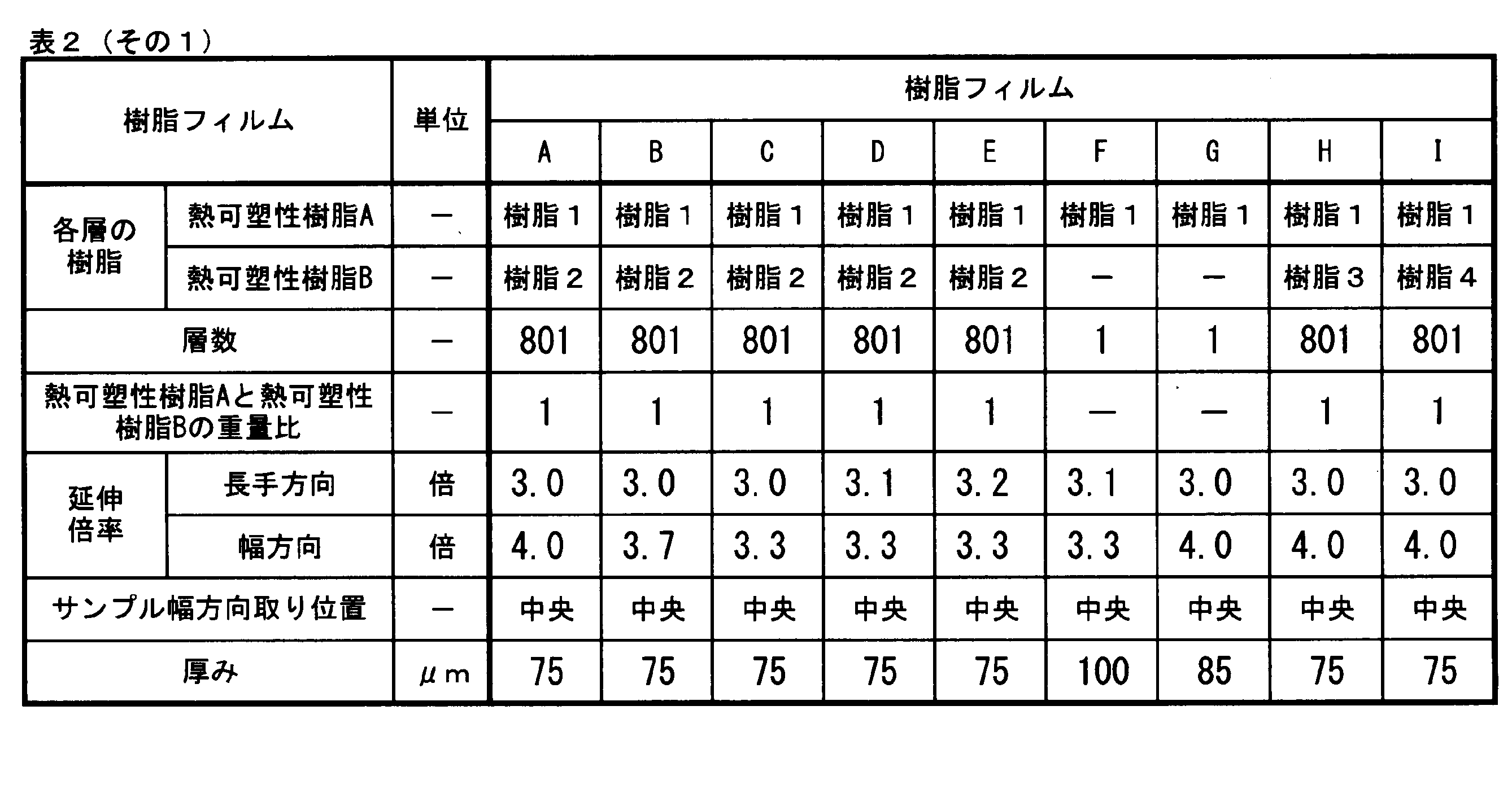
- the resins shown in Table 1 were used to obtain the resin films used in each example and each comparative example.
- the resin 1 is a crystalline resin
- the resins 2 to 10 are amorphous resins.
- "mol%” is a ratio in which the total amount of each of the dicarboxylic acid unit and the diol unit is 100 mol%.
- thermoplastic resin A and thermoplastic resin B were put into two single-screw extruders, respectively, and melted at a temperature of 290 ° C.
- thermoplastic resin A and the thermoplastic resin B are weighed by a gear pump after passing through five FSS type leaf disk filters, respectively, and the weight ratio of the thermoplastic resin A and the thermoplastic resin B becomes 1.
- 801 layers were alternately laminated in the thickness direction so that the thermoplastic resin A was located on the outermost layers on both sides to obtain a molten resin laminate.
- the molten resin laminate was discharged from the mouthpiece, cooled and solidified by a casting drum having a temperature of 25 ° C.
- the obtained cast film was heated in a roll group set at a temperature of 60 ° C., and then stretched 3.0 times at a stretching rate of 50% / sec on a roll set at a temperature of 85 ° C. in the longitudinal direction of the film. After that, it was once cooled.
- the uniaxially stretched film thus obtained was guided to a tenter, preheated with hot air at a temperature of 90 ° C., and then stretched 4.0 times at a temperature of 95 ° C. in the film width direction at a stretching rate of 5% / sec.
- the stretched film was directly heat-treated in a tenter with hot air at 215 ° C., subsequently relaxed by 1% in the width direction under the same temperature conditions, and then cooled to room temperature. Subsequently, both end edges in the width direction were cut and removed evenly to obtain a roll of a resin film having a thickness of 75 ⁇ m and a width of 400 mm.
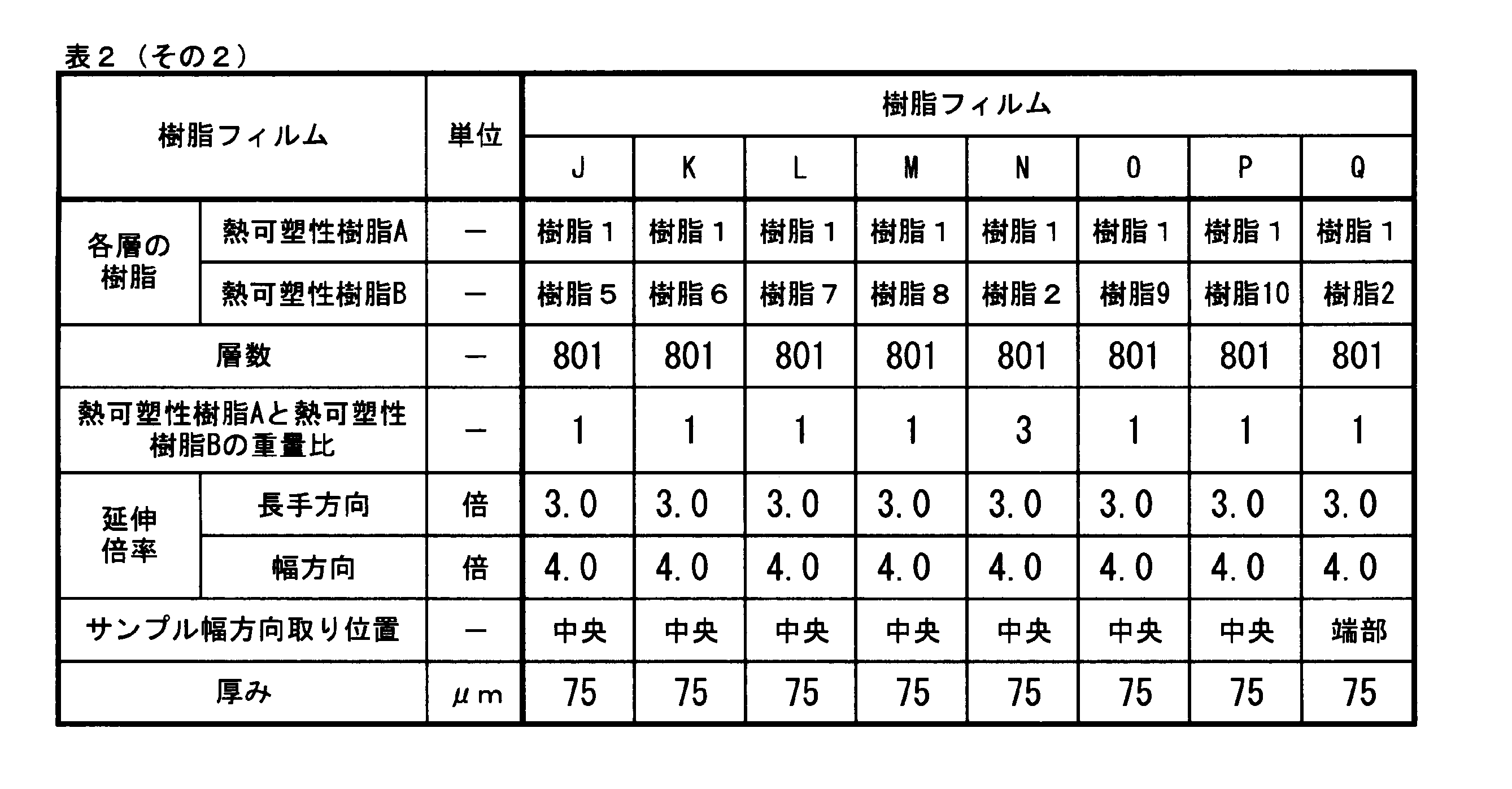
- a resin film A having a thickness of 75 ⁇ m was obtained by collecting 100 mm ⁇ 100 mm at the center position in the film width direction. Similarly, 100 mm ⁇ 100 mm was collected from the widthwise end of the roll to obtain a resin film Q having a thickness of 75 ⁇ m.
- Resin films B to P Resin films B to P were obtained in the same manner as the resin film A except that the number of layers, the resin of each layer, the draw ratio, and the thickness were as shown in Table 2. The thickness was adjusted by adjusting the rotation speed of the casting drum. In the resin film F and the resin film G, the same resin was supplied to two single-screw extruders to form a film.
- Example 1 A projection light source that projects light rays that are p-polarized with respect to the incident surface when the resin film A is used as a reflecting surface, and the resin film A are provided with a high-magnification stretching direction of the resin film A and an incident surface of light from the light source.
- a HUD system was made which was arranged so as to be perpendicular to the light source. The evaluation results are shown in Table 3.
- Example 2 A glass plate having a thickness of 2 mm was bonded to one side of the resin film A via an acrylic adhesive to obtain a laminate having the following constitution.
- a HUD system was produced in which a projection light source that generates and emits p-polarization and a high-magnification stretching direction of the resin film A contained in the obtained laminate are arranged so as to be perpendicular to the incident plane.
- the evaluation results are shown in Table 3.
- Composition Resin film / adhesive layer (thickness 10 ⁇ m) / glass (thickness 2 mm).
- Example 3 A glass plate having a thickness of 2 mm was bonded to both sides of the resin film A via a polyvinyl butyral resin A (adhesive layer) having no heat shielding property to obtain a laminate having the following constitution.
- a HUD system was produced in which a projection light source that generates and emits p-polarization and a high-magnification stretching direction of the resin film A contained in the obtained laminate are arranged so as to be perpendicular to the incident plane.
- the evaluation results are shown in Table 3. Configuration: Glass (thickness 2 mm) / adhesive layer (thickness 350 ⁇ m) / resin film / adhesive layer (thickness 350 ⁇ m) / glass (thickness 2 mm).
- Examples 4 to 16, 21, Comparative Examples 1 to 3 A HUD system was produced in the same manner as in Example 2 except that the relationship between the resin film, the projection light source, and the high-magnification stretching direction and the incident surface (vertical / parallel) was as shown in Table 3. The evaluation results are shown in Table 3.
- Example 17 A magnesium fluoride film was provided as an AR layer on the surface of the resin film of Example 2 on the side where the glass was not laminated by a sputtering method, and a laminate having the following configuration was obtained.
- Example 19 A glass plate having a thickness of 2 mm is attached to one side of the resin film A via the polyvinyl butyral resin A (adhesive layer) of Example 3 and the other side of the resin film A via the polyvinyl butyral resin B (adhesive layer) of Example 18.
- a laminate having the following composition was obtained.
- a HUD system including the obtained laminate and a projection light source that generates and emits p-polarization was produced. The evaluation results are shown in Table 3. In the evaluation of the effect, the light source was placed on the glass side in contact with the polyvinyl butyral A side.
- the head-up display system of the present invention it is possible to provide a head-up display system in which uniform reflection performance is maintained even when a shadow image is projected over a wide range of a windshield, and interference colors are hard to be visually recognized even when wearing polarized sunglasses. can. Since the head-up display system of the present invention has the above-mentioned features, it can be suitably used for transportation equipment such as aircraft, ships, automobiles, railways, buildings, and digital signage.
Landscapes
- Engineering & Computer Science (AREA)
- Physics & Mathematics (AREA)
- Chemical & Material Sciences (AREA)
- General Physics & Mathematics (AREA)
- Optics & Photonics (AREA)
- Combustion & Propulsion (AREA)
- Transportation (AREA)
- Mechanical Engineering (AREA)
- Manufacturing & Machinery (AREA)
- Materials Engineering (AREA)
- Health & Medical Sciences (AREA)
- Chemical Kinetics & Catalysis (AREA)
- Medicinal Chemistry (AREA)
- Polymers & Plastics (AREA)
- Organic Chemistry (AREA)
- Instrument Panels (AREA)
Abstract
Description
影像を投射する影像投射器と、当該影像投射器からの影像が投射される樹脂フィルムとを備えたヘッドアップディスプレイシステムであって、
当該影像投射器からの影像を構成する光線において、前記樹脂フィルムを反射面としたときの入射面に対してp偏光成分の強度が全光線成分の強度の51%以上であり、
前記樹脂フィルムは、下記測定法により求めたa*の絶対値の最大値およびb*の絶対値の最大値が下式(1)および(2)を充足する入射面が水平面に対して90±10°以内となるように配置されていることを特徴とするヘッドアップディスプレイシステム。
b*の絶対値の最大値≦30 (2)
<測定法>
日立製作所製の分光光度計(U-4100 Spectrophotometer)に付属の角度可変ユニットならびにグランテーラ社製偏光子を取り付け、樹脂フィルムを反射面としたときの入射面に対してs偏光となる偏光を、入射角度40°、60°および80°で照射し、さらに該樹脂フィルムを透過した光を前記s偏光を吸収軸とした偏光子に透過させ、波長400~1600nmの範囲の透過率をそれぞれの入射角度において測定する。なおここで、スリットは2nm(可視)/自動制御(赤外)とし、ゲインは2に設定し、走査速度を600nm/分とする。得られた透過スペクトルとD65光源の分光分布とXYZ系の等色関数を用いて、各入射角度におけるa*の絶対値およびその最大値、および、b*の絶対値およびその最大値を算出した。
b*の絶対値の最大値≦30 (2)
<測定法> (この測定法を「第一の測定法」と称することがある)
日立製作所製の分光光度計(U-4100 Spectrophotometer)に付属の角度可変ユニットならびにグランテーラ社製偏光子を取り付け、樹脂フィルムを反射面としたときの入射面に対してs偏光となる偏光を、入射角度40°、60°および80°で照射し、さらに該樹脂フィルムを透過した光を前記s偏光を吸収軸とする偏光子に透過させ、波長400~1600nmの範囲の透過率をそれぞれの入射角度において測定する。なおここで、スリットは2nm(可視)/自動制御(赤外)とし、ゲインは2に設定し、走査速度を600nm/分とする。得られた透過スペクトルとD65光源の分光分布とXYZ系の等色関数を用いて、各入射角度におけるa*の絶対値およびその最大値、および、b*の絶対値およびその最大値を算出した。
b*の絶対値の最大値≦30 (2)
<測定法>
日立製作所製の分光光度計(U-4100 Spectrophotometer)に付属の角度可変ユニットならびにグランテーラ社製偏光子を取り付け、樹脂フィルムを反射面としたときの入射面に対してs偏光となる偏光を、入射角度40°、60°および80°で照射し、さらに該樹脂フィルムを透過した光を前記s偏光を吸収軸とする偏光子に透過させ、波長400~1600nmの範囲の透過率をそれぞれの入射角度において測定する。なおここで、スリットは2nm(可視)/自動制御(赤外)とし、ゲインは2に設定し、走査速度を600nm/分とする。得られた透過スペクトルとD65光源の分光分布とXYZ系の等色関数を用いて、各入射角度におけるa*の絶対値およびその最大値、および、b*の絶対値およびその最大値を算出した。
物性値の評価方法ならびに効果の評価方法は次の通りである。
王子計測機器(株)製 位相差測定装置(KOBRA-21ADH)を用いた。3.5cm×3.5cmで切り出したフィルムサンプルを装置に設置し、入射角0°におけるフィルム面内の配向軸方位を測定した。
日立製作所製の分光光度計(U-4100 Spectrophotometer)に付属の角度可変ユニットならびにグランテーラ社製偏光子を取り付け、測定検体である樹脂フィルム面を反射面としたときの入射面に対してs偏光となる偏光を入射角度40°で照射し、さらに該樹脂フィルムを透過した光を前記s偏光を吸収軸とする偏光子に透過させ、波長400~1600nmの範囲の透過率を測定した。測定条件としては、スリットは2nm(可視)/自動制御(赤外)とし、ゲインは2と設定し、走査速度を600nm/分とし、得られた透過率とD65光源の分光分布とXYZ系の等色関数を用いてa*値、b*値を算出した。入射角60°および80°としたこと以外は上記と同様の操作でa*値、b*値をそれぞれの角度に対して算出した。
日立製作所製の分光光度計(U-4100 Spectrophotometer)に付属の角度可変ユニットならびにグランテーラ社製偏光子を取り付け、測定検体である樹脂フィルム面を反射面としたときの入射面に対してs偏光となる偏光を入射角度40°で照射し、さらに該樹脂フィルムを透過した光を前記s偏光を吸収軸とする偏光子に透過させ、波長λ=450~1600nmの範囲の透過率T(λ)を測定した。測定条件としては、スリットは2nm(可視)/自動制御(赤外)とし、ゲインは2と設定し、走査速度を600nm/分とし、検出器の直前に偏光子を取り付けて透過光のうちのs偏光成分のみを検出器へと入光させた。得られた透過率のうち、波長λ=450nm~650nmの平均透過率をC(40)とすると、波長λ=450nm~650nmの透過スペクトルと、直線T(40,λ)=C(40)との交点の数をN(40)とした。入射角60°および80°としたこと以外は上記と同様の操作でN(60)およびN(80)を得た。
日立製作所製の分光光度計(U-4100 Spectrophotometer)に付属の角度可変ユニットならびにグランテーラ社製偏光子を取り付け、測定検体である樹脂フィルム面に対して入射角度20°、40°および70°のそれぞれで光を入射させ、のフィルム面を反射面とした入射面に対してp偏光となる光の波長400~1600nmの範囲の反射率を求め、また、入射角度を0°として前記p偏光と同偏光軸の光線(便宜上「p偏光」の用語を用いる)およびこれに直交する偏光軸の光線(便宜上「s偏光」の用語を用いる)の波長400~1600nmの範囲の透過率を測定し、それぞれ波長450nm~650nmの平均反射率、平均透過率を求めた。測定条件としては、スリットは2nm(可視)、自動制御(赤外)とし、ゲインは2と設定し、走査速度を600nm/分とした。
下記(a1)~(a4)の手順で求めた。
(a1) (4)と同等の手順、測定条件で、入射面と配向軸が平行となるように配置された測定検体の樹脂フィルム面の入射角度60°のp偏光の波長400~1600nmの範囲の反射スペクトルを測定した。
(a2) 前記(a1)で得た反射スペクトルから、波長450~650nmの範囲の反射率の平均値を算出した。
(a3) 樹脂フィルムを5°刻みで右方向に面内回転させながら、各回転角度おいて前記(a1)および(a2)を繰り返し、合計の回転角度が90°に達したところで測定を終えた。
(a4) 前記(a1)~(a3)の各回転角度において得られた反射率の平均値を足し合わせて平均することで、樹脂フィルムを面内回転させた場合の平均反射率(%)とした。
樹脂フィルムを25℃雰囲気下で250時間おき、入射角度70°にて該フィルム面を反射面とした入射面に対してp偏光となる光を入射したこと以外は、評価方法(5)と同様にして平均透過率を求めた。続いて、前記樹脂フィルムを100℃の雰囲気下で250時間放置し、25℃雰囲気下250時間放置後の平均透過率測定時と同一のフィルム面、同一測定箇所に対して入射角70°で該フィルム面を反射面とした入射面に対してp偏光となる光を入射させ、評価方法(4)と同様にして平均透過率を求めた。これらの値から両者の差を求め、これを波長450~650nmの平均透過率の変化量とした。
樹脂フィルムを150℃の雰囲気下で2時間おき、その後、液体測定用石英セルに入れて流動パラフィンを充填し、スガ試験機(株)製 ヘイズメーター(HGM-2DP)を用いて測定を行うことで、フィルム表面ヘイズを除いた内部ヘイズを測定した。当該測定を、無作為に測定位置を変えて10回繰り返し、その平均値を該フィルムの内部ヘイズ値とした。
下記(b1)~(b3)の手順で求めた。
(b1) 日立製作所製の分光光度計(U-4100 Spectrophotometer)に付属の角度可変ユニットならびにグランテーラ社製偏光子を取り付け、測定検体である樹脂フィルム面を反射面としたときの入射面に対してp偏光となる偏光を入射角度60°となるように入射させ、波長450~1600nmの範囲の透過スペクトルを測定した。測定条件としては、スリットは2nm(可視)/自動制御(赤外)とし、ゲインは2と設定し、走査速度を600nm/分とし、検出器の直前に偏光子を取り付けて透過光のうちのp偏光成分のみを検出器へと入光させた。得られた透過スペクトルから、波長450~650nmの範囲の透過率の平均値を算出し、透過光中のp偏光成分量Tppとした。
(b2) 前記(c1)と同様の実験を、検出器に入光させる光をs偏光成分に変えて実施し、透過光中のs偏光成分量Tpsを求めた。
(b3) 下記式1にてp偏光成分の割合(%)を算出した。
透過光中のp偏光成分の割合(%)=Tpp/(Tpp+Tps)×100 ・・・式1
(9)情報表示性
影像投射器として、ドリームメーカー社製ディスプレイ(SP-133CM)を用い、偏光子を装着して、実施例および比較例で示す樹脂フィルムあるいは積層体(情報表示部)に入射角度60°で該樹脂フィルムあるいは積層体を反射面としたときp偏光またはs偏光となる光線により影像を投射し、表示像の鮮明性と輝度の斑の有無を目視により評価した。評価基準は次の通りである。
◎:情報表示部に投影した表示像は高鮮明であり、輝度の斑もなく、使用上問題ない。
○:情報表示部に投影した表示像はわずかに輝度の斑が見られるものの、鮮明性が高く、使用上問題ない。
×:情報表示部に投影した表示像は鮮明性が悪い、あるいは輝度の斑が強く使用上問題あり。
快晴の屋外で、実施例および比較例で得た樹脂フィルムあるいは積層体を鉛直方向に対して60°傾斜させ、樹脂フィルムあるいは積層体の中心を、300mm離れた位置から偏光サングラスを着用しながら水平に見た場合の色付きの視認性評価を行った。評価基準は次のとおりである。
◎:色付きがほとんど見えない。
○:色付きがごく僅かに見えるが、使用上問題ない。
×:強い色付きが見える。
各実施例、各比較例で使用した樹脂フィルムを得るために表1に示す樹脂を使用した。なお、樹脂1は結晶性樹脂であり、樹脂2~10は非晶性樹脂である。また、「mol%」はジカルボン酸単位、ジオール単位のそれぞれにおいて、その総量を100モル%とした割合である。

樹脂フィルムA、Q:
熱可塑性樹脂AとしてIV=0.65のポリエチレンテレフタレート(樹脂1)を用いた。また、熱可塑性樹脂Bとして、ポリエチレンナフタレートの共重合体(2,6-ナフタレンジカルボン酸成分を酸成分全体に対して80mol%、イソフタル酸成分を酸成分全体に対して20mol%、分子量400のポリエチレングリコールをジオール成分全体に対して4mol%共重合したポリエチレンナフタレート、IV=0.65)(樹脂2)を用いた。準備した熱可塑性樹脂Aと熱可塑性樹脂Bを、2台の単軸押出機にそれぞれ投入し、290℃の温度で溶融させた。次いで、熱可塑性樹脂Aと熱可塑性樹脂Bを、それぞれFSSタイプのリーフディスクフィルタを5枚介した後、ギアポンプにて計量しながら、熱可塑性樹脂Aと熱可塑性樹脂Bの重量比が1となるようスリット数801個の積層装置にて合流させて、熱可塑性樹脂Aが両側の最表層に位置するように厚み方向に交互に801層積層された溶融樹脂積層体を得た。その後、溶融樹脂積層体を口金から吐出し、温度25℃のキャスティングドラムで冷却、固化してキャストフィルムを得た。得られたキャストフィルムを、60℃の温度に設定したロール群で加熱した後、フィルム長手方向に85℃の温度に設定されたロールで50%/秒の延伸速度で3.0倍に延伸し、その後一旦冷却した。このようにして得られた一軸延伸フィルムをテンターに導き、90℃の温度の熱風で予熱後、95℃の温度でフィルム幅方向に5%/秒の延伸速度で4.0倍に延伸した。延伸したフィルムは、そのままテンター内で215℃の熱風にて熱処理を行い、続いて同温度条件下で幅方向に1%の弛緩処理をした後に室温まで冷却した。続いて幅方向の両端エッジ部分を均等に断裁除去して、厚み75μm、幅400mmの樹脂フィルムのロールを得た。フィルム幅方向の中央位置を100mm×100mmを採取し、厚み75μmの樹脂フィルムAを得た。また、同様にロールの幅方向の端部から100mm×100mmを採取し厚み75μmの樹脂フィルムQを得た。
層数、各層の樹脂、延伸倍率、厚みを表2に示すとおりとした以外は樹脂フィルムAと同様に樹脂フィルムB~Pを得た。なお、厚みの調整はキャスティングドラムの回転速度の調節により行った。なお、樹脂フィルムFおよび樹脂フィルムGにおいては、2台の単軸押出機に同一の樹脂を供給して製膜した。
樹脂フィルムAを反射面としたときの入射面に対してp偏光となる光線を投射する投影光源、および樹脂フィルムAを備え、前記樹脂フィルムAの高倍率延伸方向と光源からの光の入射面と垂直な方向となるよう配置されてなるHUDシステムを作製した。評価結果を表3に示す。
樹脂フィルムAの片面に、アクリル系接着剤を介して厚み2mmのガラス板を貼り合わせて、次の構成の積層体を得た。p偏光を発生して放射する投影光源、および得られた積層体に含まれる樹脂フィルムAの高倍率延伸方向を入射面と垂直な方向となるよう配置されてなるHUDシステムを作製した。評価結果を表3に示す。
構成:樹脂フィルム/接着層(厚み10μm)/ガラス(厚み2mm)。
樹脂フィルムAの両面に、遮熱性を有さないポリビニルブチラール樹脂A(接着層)を介して厚み2mmのガラス板を貼り合わせ、次の構成の積層体を得た。p偏光を発生して放射する投影光源、および得られた積層体に含まれる樹脂フィルムAの高倍率延伸方向を入射面と垂直な方向となるよう配置されてなるHUDシステムを作製した。評価結果を表3に示す。
構成:ガラス(厚み2mm)/接着層(厚み350μm)/樹脂フィルム/接着層(厚み350μm)/ガラス(厚み2mm)。
樹脂フィルム、投影光源、高倍率延伸方向を入射面の関係(垂直/平行)を表3のとおりとした以外は実施例2と同様にHUDシステムを作製した。評価結果を表3に示す。
実施例2の積層体の樹脂フィルムのガラスが積層されていない側の面に対し、スパッタリング法によってフッ化マグネシウム膜をAR層として設け、次の構成の積層体を得た。得られた積層体と、p偏光を発生して放射する投影光源とを備えたHUDシステムを作製した。評価結果を表3に示す。なお、効果の評価においては、下記構成のAR層側に光源を置いた。
構成:AR層(厚み0.1μm)/樹脂フィルム(厚み75μm)/接着層(厚み10μm)/ガラス(厚み2mm)
(実施例18)
樹脂フィルムAの両面に、セシウムドープ酸化タングステン粒子0.035重量%と、錫ドープ酸化インジウム粒子0.14重量%を含有する遮熱性を有するポリビニルブチラール樹脂B(接着層)を介して厚み2mmのガラス板を貼り合わせ、次の構成の積層体を得た。得られた積層体と、p偏光を発生して放射する投影光源とを備えたHUDシステムを作製した。評価結果を表3に示す。
構成:ガラス(厚み2mm)/接着層(厚み350μm)/樹脂フィルム(厚み75μm)/接着層(厚み350μm)/ガラス(厚み2mm)。
樹脂フィルムAの片面に実施例3のポリビニルブチラール樹脂A(接着層)を、もう片方の面に実施例18のポリビニルブチラール樹脂B(接着層)をそれぞれ介して厚み2mmのガラス板を貼り合わせ、次の構成の積層体を得た。得られた積層体と、p偏光を発生して放射する投影光源とを備えたHUDシステムを作製した。評価結果を表3に示す。なお、効果の評価においては、ポリビニルブチラールA側と接するガラス側に光源を置いた。
構成:ガラス(厚み2mm)/接着層(厚み350μm)/樹脂フィルム(厚み75μm)/接着層(厚み350μm)/ガラス(厚み2mm)。

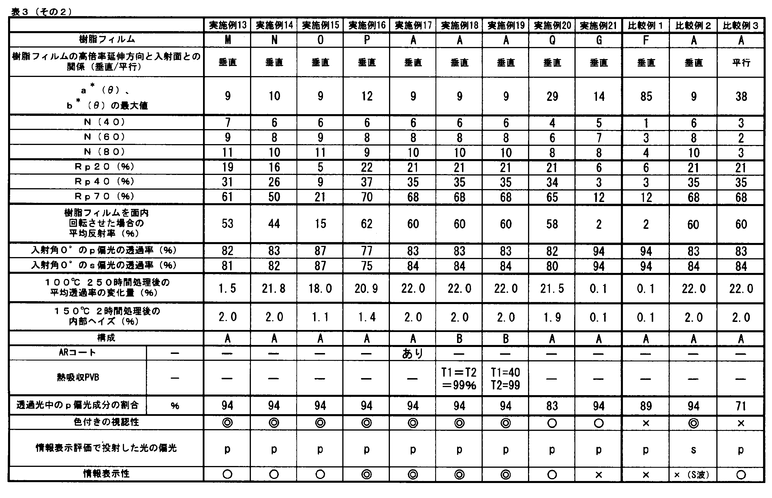
2:偏光子
3:検出器
i:入射光(s偏光)
t1:透過光(投影部透過後)
t2:透過光(投影部と偏光子透過後)
θ:入射角
T(θ,λ):光源から入射角θ°で照射したs偏光が前記樹脂フィルム及び前記偏光子を透過したときに得られる、波長λnmにおける透過率
C(θ):波長450nm~750nmの範囲内におけるT(θ,λ)の平均値
Claims (21)
- 影像を投射する影像投射器と、当該影像投射器からの影像が投射される樹脂フィルムとを備えたヘッドアップディスプレイシステムであって、
当該影像投射器からの影像を構成する光線において、前記樹脂フィルムを反射面としたときの入射面に対してp偏光成分の強度が全光線成分の強度の51%以上であり、
前記樹脂フィルムは、下記測定法により求めたa*の絶対値の最大値およびb*の絶対値の最大値が下式(1)および(2)を充足する入射面が水平面に対して90±10°以内となるように配置されていることを特徴とするヘッドアップディスプレイシステム。
a*の絶対値の最大値≦30 (1)
b*の絶対値の最大値≦30 (2)
<測定法>
日立製作所製の分光光度計(U-4100 Spectrophotometer)に付属の角度可変ユニットならびにグランテーラ社製偏光子を取り付け、樹脂フィルムを反射面としたときの入射面に対してs偏光となる偏光を、入射角度40°、60°および80°で照射し、さらに該樹脂フィルムを透過した光を前記s偏光を吸収軸とする偏光子に透過させ、波長400~1600nmの範囲の透過率をそれぞれの入射角度において測定する。なおここで、スリットは2nm(可視)/自動制御(赤外)とし、ゲインは2に設定し、走査速度を600nm/分とする。得られた透過スペクトルとD65光源の分光分布とXYZ系の等色関数を用いて、各入射角度におけるa*の絶対値およびその最大値、および、b*の絶対値およびその最大値を算出した。
なお、光線がフィルムに到達する点を中心に前記樹脂フィルムを回転させて同様の測定を行い、上記式(1)および式(2)を充足する入射面を調べることができる。 - 前記測定法で求められる透過スペクトルにおいて、透過率測定を行った際の入射角をθとしたとき、入射角θで測定した透過スペクトル中、波長450nm~750nmの範囲内における波長λnmにおける透過率をT(θ,λ)(%)、当該範囲での透過率の平均値をC(θ)(%)、当該範囲内においてT(θ,λ)=C(θ)を満たすλの数をN(θ)としたとき、N(40)、N(60)、N(80)のうち最小値が4以上である請求項1に記載のヘッドアップディスプレイシステム。
- 前記N(40)、N(60)、N(80)が、N(40)≦N(60)≦N(80)の関係を満たす、請求項2に記載のヘッドアップディスプレイシステム。
- 前記樹脂フィルムが、樹脂フィルム面を反射面としたときの入射面に対してp偏光となる光線を入射角としてそれぞれ20°、40°および70°で入射させたときの反射率(%)をRp20, Rp40, Rp70としたとき、Rp20≦Rp40<Rp70の関係を満足する請求項1~3いずれかに記載のヘッドアップディスプレイシステム。
- 前記樹脂フィルムは、樹脂フィルム面を反射面としたときの入射面に対してp偏光となる光線を入射角60°で照射しつつ、照射点を中心に0~90°の範囲でフィルム面を面内回転させた場合の平均反射率が10%以上であるものであることを特徴とする、請求項1~4のいずれかに記載のヘッドアップディスプレイシステム。
- 前記樹脂フィルムが、当該樹脂フィルムにある入射面についてp偏光となる光線を垂直入射させたときの波長450~650nmの範囲での平均反射率と、当該入射面に対してs偏光となる光線を垂直入射させたときの波長450~650nmの範囲での平均反射率が共に80%以上であることを特徴とする、請求項1~5のいずれかに記載のヘッドアップディスプレイシステム。
- 前記樹脂フィルムが、100℃で250時間処理したときの波長450~650nmの平均透過率の変化量が10%以下のフィルムである、請求項1~6のいずれかに記載のヘッドアップディスプレイシステム。
- 前記樹脂フィルムが、150℃で2時間処理した後の内部ヘイズが1%以下のフィルムである、請求項1~7のいずれかに記載のヘッドアップディスプレイシステム。
- 前記樹脂フィルムの片面に接着層を介してガラス板が積層された構成(構成A)を有する、請求項1~8のいずれかに記載のヘッドアップディスプレイシステム。
- 前記樹脂フィルムの両面に接着層を介してガラス板が積層された構成(構成B)を有する、請求項1~8のいずれかに記載のヘッドアップディスプレイシステム。
- 前記樹脂フィルムの、ガラス板が積層されていない側の面に反射防止層を有することを特徴とする、請求項9に記載のヘッドアップディスプレイシステム。
- 前記ガラス板の少なくとも一方のガラス板が、前記接着層と面していない側の面に反射防止層を有することを特徴とする、請求項10に記載のヘッドアップディスプレイシステム。
- 前記樹脂フィルムの両面の接着層をそれぞれC1、C2とした場合に、前記C1の可視・赤外光透過率T1と前記C2の可視・赤外光透過率T2がT2≠T1を満たすことを特徴とする、請求項10または12に記載のヘッドアップディスプレイシステム。
- 前記樹脂フィルムに対して入射角60°でp偏光を照射した場合の透過光に含まれるp偏光成分の割合が80%以上であることを特徴とする、請求項1~13のいずれかに記載のヘッドアップディスプレイシステム。
- 請求項1~14のいずれかに記載のヘッドアップディスプレイシステムを搭載してなることを特徴とする、輸送用機器。
- 下記測定法により求めたa*の絶対値の最大値およびb*の絶対値の最大値が下式(1)および(2)を充足する入射面を少なくともひとつ有する樹脂フィルム。
a*の絶対値の最大値≦30 (1)
b*の絶対値の最大値≦30 (2)
<測定法>
日立製作所製の分光光度計(U-4100 Spectrophotometer)に付属の角度可変ユニットならびにグランテーラ社製偏光子を取り付け、樹脂フィルムを反射面としたときの入射面に対してs偏光となる偏光を、入射角度40°、60°および80°で照射し、さらに該樹脂フィルムを透過した光を前記s偏光を吸収軸とする偏光子に透過させ、波長400~1600nmの範囲の透過率をそれぞれの入射角度において測定する。なおここで、スリットは2nm(可視)/自動制御(赤外)とし、ゲインは2に設定し、走査速度を600nm/分とする。得られた透過スペクトルとD65光源の分光分布とXYZ系の等色関数を用いて、各入射角度におけるa*の絶対値およびその最大値、および、b*の絶対値およびその最大値を算出した。
なお、光線がフィルムに到達する点を中心に前記樹脂フィルムを回転させて同様の測定を行い、上記式(1)および式(2)を充足する入射面を調べることができる。 - 前記測定法で求められる透過スペクトルにおいて、透過率測定を行った際の入射角をθとし、入射角θで測定した透過スペクトル中、波長450nm~750nmの範囲内における波長λnmにおける前記透過率をT(θ,λ)(%)、当該範囲での透過率の平均値をC(θ)(%)、当該範囲内においてT(θ,λ)=C(θ)を満たすλの数をN(θ)としたとき、N(40)、N(60)、N(80)のうち最小値が4以上である、請求項16に記載の樹脂フィルム。
- 前記N(40)、N(60)、N(80)がN(40)≦N(60)≦N(80)の関係を満たす、請求項17に記載の樹脂フィルム。
- 前記樹脂フィルムは、樹脂フィルムの面を反射面としたときの入射面に対してp偏光となる光線を入射角60°で照射しつつ、照射点を中心に0~90°の範囲でフィルム面を回転させた場合の平均反射率が10%以上であることを特徴とする、請求項16~18のいずれかに記載の樹脂フィルム。
- 前記樹脂フィルムは、100℃で250時間処理したときの波長450~650nmの平均透過率の変化量が10%以下である、請求項16~19のいずれかに記載の樹脂フィルム。
- 前記樹脂フィルムは、150℃で2時間処理した後の内部ヘイズが1%以下である、請求項16~20のいずれかに記載の樹脂フィルム。
Priority Applications (5)
| Application Number | Priority Date | Filing Date | Title |
|---|---|---|---|
| CN202180061565.9A CN116096598B (zh) | 2020-09-14 | 2021-09-10 | 平视显示系统 |
| EP21866859.8A EP4212941A4 (en) | 2020-09-14 | 2021-09-10 | HEAD-UP DISPLAY SYSTEM |
| JP2021555203A JP7279814B2 (ja) | 2020-09-14 | 2021-09-10 | ヘッドアップディスプレイシステム |
| KR1020237007158A KR102948776B1 (ko) | 2020-09-14 | 2021-09-10 | 헤드업 디스플레이 시스템 |
| US18/024,077 US12372784B2 (en) | 2020-09-14 | 2021-09-10 | Head-up display system |
Applications Claiming Priority (6)
| Application Number | Priority Date | Filing Date | Title |
|---|---|---|---|
| JP2020-153533 | 2020-09-14 | ||
| JP2020153533 | 2020-09-14 | ||
| JP2020164825 | 2020-09-30 | ||
| JP2020-164825 | 2020-09-30 | ||
| JP2021-011663 | 2021-01-28 | ||
| JP2021011663 | 2021-01-28 |
Publications (1)
| Publication Number | Publication Date |
|---|---|
| WO2022054902A1 true WO2022054902A1 (ja) | 2022-03-17 |
Family
ID=80631639
Family Applications (1)
| Application Number | Title | Priority Date | Filing Date |
|---|---|---|---|
| PCT/JP2021/033289 Ceased WO2022054902A1 (ja) | 2020-09-14 | 2021-09-10 | ヘッドアップディスプレイシステム |
Country Status (6)
| Country | Link |
|---|---|
| US (1) | US12372784B2 (ja) |
| EP (1) | EP4212941A4 (ja) |
| JP (1) | JP7279814B2 (ja) |
| KR (1) | KR102948776B1 (ja) |
| CN (1) | CN116096598B (ja) |
| WO (1) | WO2022054902A1 (ja) |
Citations (6)
| Publication number | Priority date | Publication date | Assignee | Title |
|---|---|---|---|---|
| JP2006512622A (ja) | 2002-12-31 | 2006-04-13 | スリーエム イノベイティブ プロパティズ カンパニー | 偏光光源および広角p偏光反射偏光子を備えたヘッドアップディスプレイ |
| US20140307176A1 (en) * | 2013-04-12 | 2014-10-16 | Bayerische Motoren Werke Aktiengesellschaft | Light-Transmitting Pane for Displaying an Image of a Head-Up Display for Polarized Sunglasses |
| WO2018084076A1 (ja) * | 2016-11-04 | 2018-05-11 | 富士フイルム株式会社 | ウインドシールドガラス、ヘッドアップディスプレイシステム、およびハーフミラーフィルム |
| JP2019113631A (ja) | 2017-12-21 | 2019-07-11 | パナソニック液晶ディスプレイ株式会社 | ヘッドアップディスプレイ装置 |
| WO2019198635A1 (ja) * | 2018-04-10 | 2019-10-17 | 東レ株式会社 | 積層フィルムおよび表示装置 |
| WO2020054529A1 (ja) * | 2018-09-12 | 2020-03-19 | 東レ株式会社 | 積層フィルム |
Family Cites Families (6)
| Publication number | Priority date | Publication date | Assignee | Title |
|---|---|---|---|---|
| US20130328942A1 (en) * | 2012-06-12 | 2013-12-12 | Stephen Chen | Head up display for a vehicle |
| CN104267498B (zh) * | 2014-10-14 | 2017-02-15 | 福耀玻璃工业集团股份有限公司 | 一种抬头显示系统 |
| JP2016153281A (ja) * | 2015-02-20 | 2016-08-25 | 富士フイルム株式会社 | ウインドシールドガラスおよびヘッドアップディスプレイシステム |
| JP6638077B2 (ja) * | 2016-09-06 | 2020-01-29 | マクセル株式会社 | ヘッドアップディスプレイ装置とそのための映像表示装置 |
| JP7378913B2 (ja) * | 2017-12-28 | 2023-11-14 | 大日本印刷株式会社 | 表示部材 |
| EP3885817A4 (en) | 2018-11-20 | 2022-08-17 | Central Glass Company, Limited | HEAD-UP DISPLAY DEVICE |
-
2021
- 2021-09-10 JP JP2021555203A patent/JP7279814B2/ja active Active
- 2021-09-10 CN CN202180061565.9A patent/CN116096598B/zh active Active
- 2021-09-10 KR KR1020237007158A patent/KR102948776B1/ko active Active
- 2021-09-10 WO PCT/JP2021/033289 patent/WO2022054902A1/ja not_active Ceased
- 2021-09-10 US US18/024,077 patent/US12372784B2/en active Active
- 2021-09-10 EP EP21866859.8A patent/EP4212941A4/en active Pending
Patent Citations (6)
| Publication number | Priority date | Publication date | Assignee | Title |
|---|---|---|---|---|
| JP2006512622A (ja) | 2002-12-31 | 2006-04-13 | スリーエム イノベイティブ プロパティズ カンパニー | 偏光光源および広角p偏光反射偏光子を備えたヘッドアップディスプレイ |
| US20140307176A1 (en) * | 2013-04-12 | 2014-10-16 | Bayerische Motoren Werke Aktiengesellschaft | Light-Transmitting Pane for Displaying an Image of a Head-Up Display for Polarized Sunglasses |
| WO2018084076A1 (ja) * | 2016-11-04 | 2018-05-11 | 富士フイルム株式会社 | ウインドシールドガラス、ヘッドアップディスプレイシステム、およびハーフミラーフィルム |
| JP2019113631A (ja) | 2017-12-21 | 2019-07-11 | パナソニック液晶ディスプレイ株式会社 | ヘッドアップディスプレイ装置 |
| WO2019198635A1 (ja) * | 2018-04-10 | 2019-10-17 | 東レ株式会社 | 積層フィルムおよび表示装置 |
| WO2020054529A1 (ja) * | 2018-09-12 | 2020-03-19 | 東レ株式会社 | 積層フィルム |
Non-Patent Citations (1)
| Title |
|---|
| See also references of EP4212941A4 |
Also Published As
| Publication number | Publication date |
|---|---|
| JPWO2022054902A1 (ja) | 2022-03-17 |
| KR102948776B1 (ko) | 2026-04-06 |
| KR20230074118A (ko) | 2023-05-26 |
| US12372784B2 (en) | 2025-07-29 |
| JP7279814B2 (ja) | 2023-05-23 |
| EP4212941A4 (en) | 2024-12-11 |
| CN116096598B (zh) | 2026-02-06 |
| CN116096598A (zh) | 2023-05-09 |
| EP4212941A1 (en) | 2023-07-19 |
| US20230314800A1 (en) | 2023-10-05 |
Similar Documents
| Publication | Publication Date | Title |
|---|---|---|
| TWI809081B (zh) | 積層薄膜及顯示裝置 | |
| JP2021054061A (ja) | 積層フィルム | |
| TWI805838B (zh) | 積層薄膜 | |
| JP6225495B2 (ja) | 多層積層フィルムおよびこれを用いたガラス窓部材 | |
| US12117641B2 (en) | Laminated body and manufacturing method thereof, light guide plate unit, light source unit, display device, projection image display member, projection image display device, and display screen filter | |
| JP7326726B2 (ja) | 積層フィルム | |
| CN117897638A (zh) | 多层叠层膜及投影图像显示构件 | |
| JP6891493B2 (ja) | 多層積層フィルム | |
| EP4692895A1 (en) | Head-up display | |
| JP7279814B2 (ja) | ヘッドアップディスプレイシステム | |
| JP6172027B2 (ja) | ディスプレイ用フィルム | |
| JP2024110078A (ja) | 投影画像表示部材 | |
| JP6291830B2 (ja) | 多層積層フィルム | |
| JP2023121739A (ja) | 多層積層フィルム | |
| JP7687003B2 (ja) | 積層フィルム | |
| JP7848887B2 (ja) | 積層フィルム | |
| JP2026068791A (ja) | 投影画像表示部材、及びヘッドアップディスプレイシステム | |
| WO2025053125A1 (ja) | 多層積層フィルムおよび投影画像表示部材 | |
| JP2025121469A (ja) | 透明ディスプレイシステム | |
| JP2022140986A (ja) | 積層体 | |
| WO2026042605A1 (ja) | 投影画像表示部材、及びヘッドアップディスプレイシステム |
Legal Events
| Date | Code | Title | Description |
|---|---|---|---|
| ENP | Entry into the national phase |
Ref document number: 2021555203 Country of ref document: JP Kind code of ref document: A |
|
| 121 | Ep: the epo has been informed by wipo that ep was designated in this application |
Ref document number: 21866859 Country of ref document: EP Kind code of ref document: A1 |
|
| WWE | Wipo information: entry into national phase |
Ref document number: 2021866859 Country of ref document: EP |
|
| NENP | Non-entry into the national phase |
Ref country code: DE |
|
| ENP | Entry into the national phase |
Ref document number: 2021866859 Country of ref document: EP Effective date: 20230414 |
|
| WWG | Wipo information: grant in national office |
Ref document number: 18024077 Country of ref document: US |