WO2022054958A1 - 射出成形機 - Google Patents
射出成形機 Download PDFInfo
- Publication number
- WO2022054958A1 WO2022054958A1 PCT/JP2021/033653 JP2021033653W WO2022054958A1 WO 2022054958 A1 WO2022054958 A1 WO 2022054958A1 JP 2021033653 W JP2021033653 W JP 2021033653W WO 2022054958 A1 WO2022054958 A1 WO 2022054958A1
- Authority
- WO
- WIPO (PCT)
- Prior art keywords
- injection
- resin
- mold
- screw
- molding machine
- Prior art date
- Legal status (The legal status is an assumption and is not a legal conclusion. Google has not performed a legal analysis and makes no representation as to the accuracy of the status listed.)
- Ceased
Links
Images








Classifications
-
- B—PERFORMING OPERATIONS; TRANSPORTING
- B29—WORKING OF PLASTICS; WORKING OF SUBSTANCES IN A PLASTIC STATE IN GENERAL
- B29C—SHAPING OR JOINING OF PLASTICS; SHAPING OF MATERIAL IN A PLASTIC STATE, NOT OTHERWISE PROVIDED FOR; AFTER-TREATMENT OF THE SHAPED PRODUCTS, e.g. REPAIRING
- B29C45/00—Injection moulding, i.e. forcing the required volume of moulding material through a nozzle into a closed mould; Apparatus therefor
- B29C45/17—Component parts, details or accessories; Auxiliary operations
- B29C45/46—Means for plasticising or homogenising the moulding material or forcing it into the mould
- B29C45/47—Means for plasticising or homogenising the moulding material or forcing it into the mould using screws
- B29C45/50—Axially movable screw
- B29C45/52—Non-return devices
-
- B—PERFORMING OPERATIONS; TRANSPORTING
- B29—WORKING OF PLASTICS; WORKING OF SUBSTANCES IN A PLASTIC STATE IN GENERAL
- B29C—SHAPING OR JOINING OF PLASTICS; SHAPING OF MATERIAL IN A PLASTIC STATE, NOT OTHERWISE PROVIDED FOR; AFTER-TREATMENT OF THE SHAPED PRODUCTS, e.g. REPAIRING
- B29C45/00—Injection moulding, i.e. forcing the required volume of moulding material through a nozzle into a closed mould; Apparatus therefor
- B29C45/17—Component parts, details or accessories; Auxiliary operations
- B29C45/46—Means for plasticising or homogenising the moulding material or forcing it into the mould
- B29C45/47—Means for plasticising or homogenising the moulding material or forcing it into the mould using screws
- B29C45/50—Axially movable screw
-
- B—PERFORMING OPERATIONS; TRANSPORTING
- B29—WORKING OF PLASTICS; WORKING OF SUBSTANCES IN A PLASTIC STATE IN GENERAL
- B29C—SHAPING OR JOINING OF PLASTICS; SHAPING OF MATERIAL IN A PLASTIC STATE, NOT OTHERWISE PROVIDED FOR; AFTER-TREATMENT OF THE SHAPED PRODUCTS, e.g. REPAIRING
- B29C45/00—Injection moulding, i.e. forcing the required volume of moulding material through a nozzle into a closed mould; Apparatus therefor
- B29C45/17—Component parts, details or accessories; Auxiliary operations
- B29C45/46—Means for plasticising or homogenising the moulding material or forcing it into the mould
- B29C45/57—Exerting after-pressure on the moulding material
-
- B—PERFORMING OPERATIONS; TRANSPORTING
- B29—WORKING OF PLASTICS; WORKING OF SUBSTANCES IN A PLASTIC STATE IN GENERAL
- B29C—SHAPING OR JOINING OF PLASTICS; SHAPING OF MATERIAL IN A PLASTIC STATE, NOT OTHERWISE PROVIDED FOR; AFTER-TREATMENT OF THE SHAPED PRODUCTS, e.g. REPAIRING
- B29C45/00—Injection moulding, i.e. forcing the required volume of moulding material through a nozzle into a closed mould; Apparatus therefor
- B29C45/17—Component parts, details or accessories; Auxiliary operations
- B29C45/46—Means for plasticising or homogenising the moulding material or forcing it into the mould
- B29C45/58—Details
- B29C45/60—Screws
-
- B—PERFORMING OPERATIONS; TRANSPORTING
- B29—WORKING OF PLASTICS; WORKING OF SUBSTANCES IN A PLASTIC STATE IN GENERAL
- B29C—SHAPING OR JOINING OF PLASTICS; SHAPING OF MATERIAL IN A PLASTIC STATE, NOT OTHERWISE PROVIDED FOR; AFTER-TREATMENT OF THE SHAPED PRODUCTS, e.g. REPAIRING
- B29C45/00—Injection moulding, i.e. forcing the required volume of moulding material through a nozzle into a closed mould; Apparatus therefor
- B29C45/17—Component parts, details or accessories; Auxiliary operations
- B29C45/76—Measuring, controlling or regulating
-
- B—PERFORMING OPERATIONS; TRANSPORTING
- B29—WORKING OF PLASTICS; WORKING OF SUBSTANCES IN A PLASTIC STATE IN GENERAL
- B29C—SHAPING OR JOINING OF PLASTICS; SHAPING OF MATERIAL IN A PLASTIC STATE, NOT OTHERWISE PROVIDED FOR; AFTER-TREATMENT OF THE SHAPED PRODUCTS, e.g. REPAIRING
- B29C45/00—Injection moulding, i.e. forcing the required volume of moulding material through a nozzle into a closed mould; Apparatus therefor
- B29C45/17—Component parts, details or accessories; Auxiliary operations
- B29C45/76—Measuring, controlling or regulating
- B29C45/7653—Measuring, controlling or regulating mould clamping forces
-
- B—PERFORMING OPERATIONS; TRANSPORTING
- B29—WORKING OF PLASTICS; WORKING OF SUBSTANCES IN A PLASTIC STATE IN GENERAL
- B29C—SHAPING OR JOINING OF PLASTICS; SHAPING OF MATERIAL IN A PLASTIC STATE, NOT OTHERWISE PROVIDED FOR; AFTER-TREATMENT OF THE SHAPED PRODUCTS, e.g. REPAIRING
- B29C45/00—Injection moulding, i.e. forcing the required volume of moulding material through a nozzle into a closed mould; Apparatus therefor
- B29C45/17—Component parts, details or accessories; Auxiliary operations
- B29C45/76—Measuring, controlling or regulating
- B29C45/77—Measuring, controlling or regulating of velocity or pressure of moulding material
-
- B—PERFORMING OPERATIONS; TRANSPORTING
- B29—WORKING OF PLASTICS; WORKING OF SUBSTANCES IN A PLASTIC STATE IN GENERAL
- B29C—SHAPING OR JOINING OF PLASTICS; SHAPING OF MATERIAL IN A PLASTIC STATE, NOT OTHERWISE PROVIDED FOR; AFTER-TREATMENT OF THE SHAPED PRODUCTS, e.g. REPAIRING
- B29C45/00—Injection moulding, i.e. forcing the required volume of moulding material through a nozzle into a closed mould; Apparatus therefor
- B29C45/17—Component parts, details or accessories; Auxiliary operations
- B29C45/1761—Means for guiding movable mould supports or injection units on the machine base or frame; Machine bases or frames
- B29C2045/1762—Means for guiding movable mould supports or injection units on the machine base or frame; Machine bases or frames compensating frame distortion proportional to the mould clamping force
-
- B—PERFORMING OPERATIONS; TRANSPORTING
- B29—WORKING OF PLASTICS; WORKING OF SUBSTANCES IN A PLASTIC STATE IN GENERAL
- B29C—SHAPING OR JOINING OF PLASTICS; SHAPING OF MATERIAL IN A PLASTIC STATE, NOT OTHERWISE PROVIDED FOR; AFTER-TREATMENT OF THE SHAPED PRODUCTS, e.g. REPAIRING
- B29C45/00—Injection moulding, i.e. forcing the required volume of moulding material through a nozzle into a closed mould; Apparatus therefor
- B29C45/17—Component parts, details or accessories; Auxiliary operations
- B29C45/18—Feeding the material into the injection moulding apparatus, i.e. feeding the non-plastified material into the injection unit
- B29C45/1816—Feeding auxiliary material, e.g. colouring material
- B29C2045/185—Feeding auxiliary material, e.g. colouring material controlling the amount of auxiliary material
-
- B—PERFORMING OPERATIONS; TRANSPORTING
- B29—WORKING OF PLASTICS; WORKING OF SUBSTANCES IN A PLASTIC STATE IN GENERAL
- B29C—SHAPING OR JOINING OF PLASTICS; SHAPING OF MATERIAL IN A PLASTIC STATE, NOT OTHERWISE PROVIDED FOR; AFTER-TREATMENT OF THE SHAPED PRODUCTS, e.g. REPAIRING
- B29C45/00—Injection moulding, i.e. forcing the required volume of moulding material through a nozzle into a closed mould; Apparatus therefor
- B29C45/17—Component parts, details or accessories; Auxiliary operations
- B29C45/46—Means for plasticising or homogenising the moulding material or forcing it into the mould
- B29C45/56—Means for plasticising or homogenising the moulding material or forcing it into the mould using mould parts movable during or after injection, e.g. injection-compression moulding
- B29C45/561—Injection-compression moulding
- B29C2045/5625—Closing of the feed opening before or during compression
-
- B—PERFORMING OPERATIONS; TRANSPORTING
- B29—WORKING OF PLASTICS; WORKING OF SUBSTANCES IN A PLASTIC STATE IN GENERAL
- B29C—SHAPING OR JOINING OF PLASTICS; SHAPING OF MATERIAL IN A PLASTIC STATE, NOT OTHERWISE PROVIDED FOR; AFTER-TREATMENT OF THE SHAPED PRODUCTS, e.g. REPAIRING
- B29C45/00—Injection moulding, i.e. forcing the required volume of moulding material through a nozzle into a closed mould; Apparatus therefor
- B29C45/17—Component parts, details or accessories; Auxiliary operations
- B29C45/46—Means for plasticising or homogenising the moulding material or forcing it into the mould
- B29C45/56—Means for plasticising or homogenising the moulding material or forcing it into the mould using mould parts movable during or after injection, e.g. injection-compression moulding
- B29C45/561—Injection-compression moulding
- B29C2045/566—Reducing compression pressure during cooling of the moulded material
-
- B—PERFORMING OPERATIONS; TRANSPORTING
- B29—WORKING OF PLASTICS; WORKING OF SUBSTANCES IN A PLASTIC STATE IN GENERAL
- B29C—SHAPING OR JOINING OF PLASTICS; SHAPING OF MATERIAL IN A PLASTIC STATE, NOT OTHERWISE PROVIDED FOR; AFTER-TREATMENT OF THE SHAPED PRODUCTS, e.g. REPAIRING
- B29C45/00—Injection moulding, i.e. forcing the required volume of moulding material through a nozzle into a closed mould; Apparatus therefor
- B29C45/17—Component parts, details or accessories; Auxiliary operations
- B29C45/46—Means for plasticising or homogenising the moulding material or forcing it into the mould
- B29C45/57—Exerting after-pressure on the moulding material
- B29C45/572—Exerting after-pressure on the moulding material using movable mould wall or runner parts
- B29C2045/575—Exerting after-pressure on the moulding material using movable mould wall or runner parts preventing backflow of moulding material to the injection means during after-pressure
-
- B—PERFORMING OPERATIONS; TRANSPORTING
- B29—WORKING OF PLASTICS; WORKING OF SUBSTANCES IN A PLASTIC STATE IN GENERAL
- B29C—SHAPING OR JOINING OF PLASTICS; SHAPING OF MATERIAL IN A PLASTIC STATE, NOT OTHERWISE PROVIDED FOR; AFTER-TREATMENT OF THE SHAPED PRODUCTS, e.g. REPAIRING
- B29C2945/00—Indexing scheme relating to injection moulding, i.e. forcing the required volume of moulding material through a nozzle into a closed mould
- B29C2945/76—Measuring, controlling or regulating
- B29C2945/76822—Phase or stage of control
- B29C2945/76846—Metering
-
- B—PERFORMING OPERATIONS; TRANSPORTING
- B29—WORKING OF PLASTICS; WORKING OF SUBSTANCES IN A PLASTIC STATE IN GENERAL
- B29C—SHAPING OR JOINING OF PLASTICS; SHAPING OF MATERIAL IN A PLASTIC STATE, NOT OTHERWISE PROVIDED FOR; AFTER-TREATMENT OF THE SHAPED PRODUCTS, e.g. REPAIRING
- B29C2945/00—Indexing scheme relating to injection moulding, i.e. forcing the required volume of moulding material through a nozzle into a closed mould
- B29C2945/76—Measuring, controlling or regulating
- B29C2945/76822—Phase or stage of control
- B29C2945/76876—Switch-over
- B29C2945/76886—Switch-over holding-metering
Definitions
- the present invention relates to an injection molding machine that injects and fills a mold that has been molded by a predetermined mold clamping force with a resin at a predetermined injection pressure to perform molding.
- This injection molding machine ensures a high degree of quality and homogeneity of molded products even for low-viscosity resins that are sensitive to temperature, pressure, etc., and simplifies molding conditions and makes setting easy.
- the purpose is to improve mass productivity and economic efficiency by facilitating quality control and shortening the molding cycle time.
- a mold clamping device By using a mold clamping device that enables natural compression of the resin at least as the resin in the mold solidifies, a predetermined mold gap is created between the movable mold and the fixed mold at the time of injection filling in advance, and good product molding is possible.
- the molding injection pressure and the molding mold clamping force are obtained and set, and at the time of production, the mold clamping device is molded by the molding mold clamping force, the molding injection pressure is set as the limiter pressure, and the injection device is driven to drive the mold.
- the injection filling of the resin is performed.
- a molded product when a molded product is produced by an injection molding machine, it is usually molded by setting various molding conditions such as injection speed, injection pressure, resin temperature, etc., which match the type of molded product.
- the obtained molded product has some molding defects, and in particular, there are some molded products in which molding defects are likely to occur depending on the type of the molded product and the like.
- molding using recycled pellet material which has a tendency to have a non-uniform pellet shape compared to normal pellets due to the mixing of high-cycle molded products, crushed materials, etc., which have a short plasticization time and do not easily transfer sufficient heat to the resin.
- Products, molded products with a large injection capacity that require large-capacity plasticization at one time, etc. are particularly prone to molding defects and a decrease in yield rate (non-defective product rate).
- the present invention aims to provide an injection molding machine that solves the problems existing in such background technology.
- the injection molding machine M includes a mold clamping device Mc that clamps a mold 2 composed of a fixed mold 2c and a movable mold 2 m with a predetermined mold clamping force in order to solve the above-mentioned problems.
- An injection molding machine including an injection device Mi that injects and fills a resin with a predetermined injection pressure into the molded mold 2 and a molding machine controller C that controls the mold clamping device Mc and the injection device Mi.
- the resin R in front of the screw head portion 4s is injection-filled in the mold 2 and at the same time, a predetermined amount of resin is injected.
- the injection molding machine M according to the first embodiment has a predetermined amount in the range of 10-60 [%] with respect to the capacity of the resin R to be injection-filled in the mold 2 according to a preferred embodiment of the invention. It is desirable to select.
- the screw head portion 4s is provided with at least one recirculation passage 11 ... It can be configured by providing an injection pressure additional setting function unit Fs that sets a predetermined amount higher than the injection pressure Pi when the screw does not return, or a reverse rotation control function unit Fc that reversely rotates the screw 4 is provided.
- the reverse rotation control function unit Fc may be provided with the reverse rotation setting function unit Fcs for the period in which the screw 4 is rotated in the reverse direction and the rotation speed.
- a mold clamping device a mold clamping device Mc that enables natural compression of the resin R at least as the resin R in the mold 2 is solidified is used, and a movable mold is previously used in the molding machine controller C at the time of injection filling.
- a predetermined mold gap Lm is generated between the 2m and the fixed mold 2c, and the injection pressure (hereinafter, molding injection pressure) Pi that can be molded into a good product and the mold clamping force (hereinafter, molding mold clamping force) Pc that can be molded into a good product are obtained.
- the mold clamping device Mc is molded by the molding mold clamping force Pc, and the molding injection pressure Pi is set as the limiter pressure Ps to drive the injection device Mi to drive the resin R with respect to the mold 2.
- a control function for injection filling can be provided.
- the injection molding machine M is a mold clamping device that clamps a mold 2 composed of a fixed mold 2c and a movable mold 2 m by a predetermined mold clamping force in order to solve the above-mentioned problems.
- An injection molding machine including Mc, an injection device Mi that injects and fills a resin with a predetermined injection pressure to the molded mold 2, and a molding machine controller C that controls the mold clamping device Mc and the injection device Mi.
- the injection molding machine M according to the second embodiment can use an injection device provided with a shut-off nozzle (or valve nozzle) 51 as the injection device Mi according to a preferred embodiment of the invention.
- a mold clamping device a mold clamping device Mc that enables natural compression of the resin R at least as the resin R in the mold 2 is solidified is used, and a movable mold is previously used in the molding machine controller C at the time of injection filling.
- a predetermined mold gap Lm is generated between 2 m and the fixed mold 2c, and the molding injection pressure Pi capable of forming a good product and the molding mold clamping force Pc capable of forming a good product are obtained and set.
- the clamping device Mc By molding the clamping device Mc and setting the molding injection pressure Pi as the limiter pressure Ps, it is possible to provide a control function for driving the injection device Mi to inject and fill the mold 2 with the resin R.
- the plasticization promotion step Wi3 when the plasticized storage resin R is refluxed, it may be refluxed by the forward pressure control function for the screw 4 or it may be refluxed by the reverse rotation control function for the screw 4. good.
- an auxiliary plasticizing treatment (S121) for securing the amount of the reflux resin Rm can be performed before the substantial plasticization promoting treatment (S122) is carried out.
- an auxiliary plasticizing treatment part for performing the auxiliary plasticizing treatment and a plasticization promoting treatment part for performing the plasticization promoting treatment are set, and the auxiliary plasticizing treatment part (S201) and the plasticization promoting treatment part (S202) based on this setting are set.
- the combination step of the above can be repeated within a preset number of times N or within an allowable time of the plasticization promoting step Wi3.
- the amount (predetermined amount) of the reflux resin Rm is 10-60 [with respect to the capacity of the resin R to be injected and filled in the mold 2. %] Can be selected to achieve a good balance between production efficiency and yield rate in the production of molded products. Therefore, both should be optimized from the viewpoint of ensuring production efficiency and yield rate. be able to.
- At least one reflux passage 11 in which the resin Rm is refluxed to the screw head portion 4s when the partial reflux injection function portion 5 is configured is configured. If the screw head portion 4s is provided, it can be realized by changing the screw head portion 4s or by performing additional processing, so that it can be easily and inexpensively carried out, and can be easily applied to an existing injection molding machine. can.
- the injection pressure Pi at the time of molding is set to the injection pressure Pi when the resin R does not recirculate.
- the injection pressure additional setting function unit Fs which is set higher by a predetermined size, is provided, the amount of the recirculation resin Rm (recirculation amount) can be injected even when the recirculation passage 11 ... Is provided. Since it can be arbitrarily set by the pressure additional setting function unit Fs, the recirculation amount can be easily set and the influence on the original amount (filling amount) of the resin R to be injected and filled in the mold 2 is avoided. can do.
- the reverse rotation control function unit Fc that rotates the screw 4 in the reverse direction is provided. Since it is not necessary to change the shape of the screw 4 itself, it becomes possible to recirculate the screw 4 by the control process, further facilitating the implementation, and further enhancing the versatility.
- the reverse rotation control function unit Fc when the reverse rotation control function unit Fc is provided, if the reverse rotation setting function unit Fcs for setting the period for reverse rotation of the screw 4 and the rotation speed is provided, the recirculation amount of the recirculation resin Rm can be reduced. Since it can be set by the reverse rotation setting function unit Fcs, an arbitrary recirculation amount can be easily set, and it is possible to avoid an influence on the original filling amount to be injected and filled with respect to the mold 2.
- a mold clamping device Mc that enables natural compression of the resin R at least as the resin R in the mold 2 is solidified is used as the mold clamping device, and the molding machine controller C is used in advance.
- a predetermined mold gap Lm is generated between the movable mold 2m and the fixed mold 2c at the time of injection filling, and the injection pressure (hereinafter, molding injection pressure) Pi that can mold a good product and the mold clamping force that can mold a good product (hereinafter, molding mold clamping). Force) Pc is obtained and set, and at the time of molding, the mold clamping device Mc is molded by the molding mold clamping force Pc, and the molding injection pressure Pi is set as the limiter pressure Ps to drive the injection device Mi.
- the injection molding machine M according to the second embodiment if an injection device provided with a shut-off nozzle (or valve nozzle) 51 is used for the injection device Mi, the nozzle port 3ne is required. Can be shut off, so that the plasticization promotion step Wi3 can be performed during the cooling step Wc4, the mold opening step Wc5, and the molded product taking-out step Wc6. As a result, it becomes possible to carry out a sufficient plasticization promotion treatment in terms of time, and the injection molding machine M according to the present invention can be carried out more reliably and satisfactorily.
- the injection process Wi2 is completed if the resin R is recirculated by the forward pressure control function for the screw 4. Later, after the resin in the mold 2 is sufficiently solidified, the forward pressing force on the screw 4 can be increased in a state where the molded product in the mold 2 is not affected. It can be recirculated using pressure. Therefore, it can be easily carried out by providing the screw head portion 4s with a slight reflux passage or a reflux passage having an opening / closing function, which does not cause reflux depending on the molding injection pressure Pi.
- the resin R when the resin R is recirculated in the injection molding machine M according to the second embodiment, the resin R is recirculated by the forward pressure control function and the reverse rotation control function for the screw 4. Since the recirculation amount can be adjusted by controlling the reverse rotation of the screw 4, any recirculation amount of the resin Rm can be easily and accurately set by selecting conditions such as the period for reverse rotation and the rotation speed.
- the amount of the reflux resin Rm is before the substantial plasticization promoting treatment (S122) is executed.
- the auxiliary plasticizing treatment (S121) to secure Only by performing the auxiliary plasticizing treatment (S121), the required amount of reflux resin Rm can be secured.
- the auxiliary plasticization treatment part for performing the auxiliary plasticization treatment and the plasticization promotion for carrying out the plasticization promotion treatment are performed.
- a processing part is set, and the combination process of the auxiliary plasticization processing part (S201) and the plasticization promotion processing part (S202) based on this setting is performed within a preset number of times N or within the allowable time of the plasticization promotion process Wi3.
- the cooling time is relatively long, for example, as in a large molded product, the cooling time can be effectively utilized by performing such a repeating process.
- the plasticization treatment for the resin R can be performed more uniformly and precisely, which can contribute to further quality improvement and yield rate improvement of the molded product.
- FIG. 1 A cross-sectional side view showing a part of an injection device (virtual line circle A part in FIG. 1) provided in the injection molding machine according to the first embodiment of the same embodiment.
- a bar graph showing the magnitude of various physical quantities with and without reflux by the injection molding machine.
- a flowchart for explaining a molding procedure by an injection molding method using the injection molding machine Explanatory drawing showing the behavior of the resin in the plasticization process of the injection molding machine, Explanatory drawing showing the behavior of the resin in the molding process of the injection molding machine, Relationship diagram of time vs.
- a cross-sectional side view showing a part of an injection device (virtual line circle A part in FIG. 1) provided in the injection molding machine according to the second embodiment of the same embodiment.
- Relationship diagram of screw reverse rotation and recirculation rate when using the same injection molding machine A cross-sectional side view showing a part of the injection device (virtual line circle A part in FIG. 1) according to the modified example of the first embodiment of the same embodiment.
- M is an injection molding machine, which includes an injection device Mi and a mold clamping device Mc.
- the injection device Mi is provided with a heating cylinder 3 having an injection nozzle 3n at the front end and a hopper 21 at the rear, and a screw 4 is inserted inside the heating cylinder 3 and a screw is driven at the rear end of the heating cylinder 3.
- the portion 23 is arranged.
- the screw drive unit 23 includes an injection cylinder (hydraulic cylinder) 24 containing a single rod type injection ram 24r, and the ram rod 24rs projecting forward of the injection cylinder 24 is coupled to the rear end of the screw 4.
- a shaft of a metering motor (oil motor) 25 attached to the injection cylinder 24 is spline-coupled to the rear end of the injection ram 24r.
- Reference numeral 26 denotes an injection device moving cylinder that moves the injection device Mi forward and backward to touch the nozzle with respect to the mold 2 or release the nozzle. As a result, the injection device Mi can touch the injection nozzle 3n to the mold 2 and inject and fill the molten (plasticized) resin R (FIG. 5) in the cavity of the mold 2.
- the mold clamping device Mc is a direct pressure type hydraulic mold clamping device that displaces the movable mold 2 m by the drive ram 27r of the mold clamping cylinder (hydraulic cylinder) 27.
- This mold clamping device Mc is provided with a fixed plate 28 whose position is fixed and is arranged apart from each other, and is a movable plate slidably mounted on a plurality of tie bars 29 ... erected between the fixed plate 28 and the mold clamping cylinder 27. 30 is provided.
- the tip of the ram rod 27rs protruding forward from the mold clamping cylinder 27 is fixed to the movable plate 30.
- the fixed mold 2c is attached to the fixed plate 28, and the movable mold 2m is attached to the movable plate 30.
- the fixed mold 2c and the movable mold 2m form the mold 2.
- the mold clamping cylinder 27 can open and close the mold 2 and perform mold clamping.
- this mold clamping device Mc can naturally compress the resin R at least as the resin R in the mold 2 solidifies. be.
- the injection molding machine M includes the hydraulic circuit 35 shown in FIG. 1, and the hydraulic circuit 35 includes a variable discharge type hydraulic pump 36 and a valve circuit 37 which are hydraulic drive sources, and drives and controls the hydraulic pump 36.
- a pump circuit 38 is provided. Since the hydraulic pump 36 has a built-in swash plate (not shown), if the inclination angle (swash plate angle) of the swash plate is increased, the stroke of the pump piston is increased, the discharge flow rate can be increased, and the swash plate can be increased. If the angle is made small, the stroke of the pump piston becomes small, and the discharge flow rate can be reduced. Therefore, if the swash plate angle is set to a predetermined angle, it is possible to set a fixed discharge flow rate in which the discharge flow rate (maximum capacity) is fixed to a predetermined size.
- the discharge port of the hydraulic pump 36 is connected to the primary side of the valve circuit 37, and the secondary side of the valve circuit 37 is the injection cylinder 24, the measuring motor 25, the mold clamping cylinder 27, and the ejector in the injection molding machine M. It is connected to the cylinder 31 and the injection device moving cylinder 26. Therefore, the valve circuit 37 includes a switching valve (solenoid valve) connected to the injection cylinder 24, the measuring motor 25, the mold clamping cylinder 27, the ejector cylinder 31, and the injection device moving cylinder 26, respectively. Each switching valve is composed of one or more valve parts, necessary accessory hydraulic parts, etc., and at least the injection cylinder 24, the measuring motor 25, the mold clamping cylinder 27, the ejector cylinder 31, and the injection device movement. It has a switching function related to supply, stop, and discharge of hydraulic oil to the cylinder 26.
- the pump circuit 38 can change the discharge flow rate and the discharge pressure by controlling the pump motor (servo motor) of the variable discharge type hydraulic pump 36, and based on this, the above-mentioned injection cylinder 24, measuring motor 25, It is possible to control the drive of the mold clamping cylinder 27, the ejector cylinder 31, and the injection device moving cylinder 26, and also to control each operation process in the molding cycle.
- the pump capacity can be set to the fixed discharge flow rate (maximum capacity) of a predetermined size, and the fixed discharge flow rate can be set. Since the discharge flow rate and the discharge pressure can be changed based on the flow rate, easy and smooth control can be performed.
- the injection molding machine M includes a control system 41 shown in FIG.
- the control system 41 has a control function for executing a molding process in a specific molding mode.
- a predetermined mold gap Lm is generated between the movable mold 2m and the fixed mold 2c at the time of injection filling, and the molding injection pressure Pi capable of molding a good product and the molding mold clamping force Pc capable of molding a good product are obtained in advance.
- the mold clamping device Mc is molded by the molding mold clamping force Pc, the molding injection pressure Pi is set as the limiter pressure Ps, and the injection device Mi is driven to inject the resin R into the mold 2. It is a molding method that fills.
- the control system 41 includes a molding machine controller main body 42c and a molding machine controller C having a display 42d attached to the molding machine controller main body 42c.
- the molding machine controller main body 42c has a computer function having built-in hardware such as a CPU and an internal memory, and a control program (software) for executing various arithmetic processing and various control processing (sequence control) in the attached internal memory 42m. ) Is included in the program area 42mp for storing various programs, and the data area 42md for storing various data (databases) is included. Therefore, the software for executing the above-mentioned specific molding mode is stored in the program area 42mp, and can be made to function as the specific molding mode function unit Fa.
- the display 42d includes a display main body 42dd and a touch panel 42dt attached to the display main body 42dd, and the display main body 42dd and the touch panel 42dt are connected to the molding machine controller main body 42c via a display interface (not shown). Therefore, various setting operations, selection operations, and the like can be performed by the touch panel 42dt.
- various sensors 43 including a mold gap sensor for detecting at least the mold gap Lm and various switches 44 are connected to the molding machine controller main body 42c, and the pump circuit 38 and the valve circuit 37 described above are connected to the molding machine controller main body 42c. do.
- the injection molding machine M advances a partial recirculation injection function unit 5, that is, a screw 4 housed in a heating cylinder 3 of the injection device Mi, which constitutes a main part of the present invention.
- a partial recirculation injection function unit 5 that recirculates through the inner side and / or the outer peripheral portion side of the screw head portion 4s to the screw main body portion 4 m side behind the screw head portion 4s.
- the molding machine controller C stores software for partially functioning the reflux injection function unit 5, and the software allows the injection pressure additional setting function unit Fs, which will be described later, to be stored.
- the reverse rotation control function unit Fc and the reverse rotation setting function unit Fc can be made to function respectively.
- FIG. 2 is an extraction enlarged view of a part of the injection device Mi in the injection molding machine M shown in FIG. 1, that is, the virtual line circle A part, and includes the partial reflux injection function part 5 according to the first embodiment. A part of the injection device Mi is shown.
- reference numeral 4 denotes a screw, which has a spiral screw flight 4f on the peripheral surface of the screw main body 4 m and a screw head portion 4s at the front end of the screw 4.
- the illustrated screw head portion 4s has a conical tip portion 4sc at the front end, and the rear end surface of the conical tip portion 4sc is attached to the front end surface of the screw main body portion 4m via the mounting shaft portion 4sj arranged in the axial direction Ds.
- a cylindrical check valve portion 4sn that can be moved back and forth is arranged between the conical tip portion 4sc and the screw main body portion 4m.
- the function of the check valve in the molding mode by a general injection molding machine is as follows. First, in the weighing step, the check valve moves to the front open position as the resin moves because the measuring is performed so that the resin moves from the screw main body side to the front of the screw head portion. That is, the resin is allowed to move forward. Further, in the injection process, the measured resin pressure acts backward, so that the check valve moves to the rear closed position. As a result, the backflow of the resin is blocked by the check valve. Therefore, the shape of the check valve is cylindrical, and the outer peripheral surface of the check valve comes into contact with the inner peripheral surface of the heating cylinder so that there is almost no gap and the check valve is inwardly formed. , The flowable resin passage of the resin is blocked.
- the entire check valve portion 4sn is formed into a cylindrical shape, and the reflux resin Rm is formed on the outer peripheral surface thereof.
- the reflux passage 11 is formed by a linear groove parallel to the axial direction Ds, and the size of the cross-sectional area of the reflux passage 11 is such that the amount of the reflux resin Rm (reflux amount) is injection-filled in the mold 2. It is desirable to select it so that it is in the range of 10-60 [%] with respect to the capacity of the resin R. With this selection, it is possible to strike a good balance between production efficiency and yield rate in the production of molded products. Therefore, it is possible to optimize both from the viewpoint of ensuring production efficiency and yield rate. can.
- 12 indicates a resin passage provided between the inner peripheral surface of the check valve portion 4sn and the outer peripheral surface of the mounting shaft portion 4sj, and 13 ... Are a plurality formed on the outer peripheral surface of the conical tip portion 4sc.
- the resin passage of is shown. Therefore, the resin passages 13 ... Are notched at equidistant positions in the circumferential direction.
- the resin passage 12 and the resin passage 13 are blocked.
- the molding machine controller C is provided with an injection pressure additional setting function unit Fs capable of changing the molding injection pressure Pi (limiter pressure Ps) described later.
- the injection pressure additional setting function unit Fs has at least a function of setting the injection pressure Pi at the time of molding higher by a predetermined magnitude with respect to the molding injection pressure Pi when the resin R does not recirculate.
- the recirculation amount of the recirculation resin Rm can be arbitrarily set by the injection pressure additional setting function unit Fs even when the recirculation passage 11 ... Is provided. Therefore, the recirculation amount can be easily set, and the influence on the original amount (filling amount) of the resin R to be injection-filled with respect to the mold 2 can be avoided. Therefore, it is desirable that the injection pressure Pi at the time of recirculating molding is set so as not to affect the original molding by the molding injection pressure Pi at the time of non-refluxing.
- FIG. 3 shows the magnitudes of various physical quantities at the time of molding when the resin R does not reflux (without reflux) and when a predetermined amount of refluxed resin Rm refluxes (with reflux).
- the injection peak pressure Pp corresponds to the limiter pressure Ps described later. Therefore, in the example, the injection peak pressure Pp (limiter pressure Ps) when there is no reflux is 50.5 [MPa], whereas the injection molding machine M according to the present embodiment is used with reflux.
- the injection molding method the case where the value is set to 52.5 [MPa], which is a slightly larger value than that without reflux, is shown.
- the injection peak pressure Pp (limiter pressure Ps) can be set by the injection pressure additional setting function unit Fs.
- the injection capacity Qi with no reflux increased to 71.2 [cubic centimeters]
- the injection stroke Xi of the screw at the time of injection is 44.8 [mm] when there is no reflux, whereas it becomes 61.4 [mm] when there is reflux. The result is shown.
- the injection pressure additional setting function for setting the injection pressure Pi at the time of molding higher by a predetermined magnitude with respect to the injection pressure Pi when the resin R does not recirculate. If the part Fs is provided, the recirculation amount of the recirculation resin Rm can be arbitrarily set by the injection pressure additional setting function unit Fs even when the recirculation passage 11 ... Is provided, so that the recirculation amount can be easily set. In addition, it is possible to avoid an influence on the original amount (filling amount) of the resin R to be injection-filled with respect to the mold 2.
- the specific molding mode used in the injection molding method of the injection molding machine M according to the present embodiment is preset.
- the basic molding procedure of this specific molding mode is the same as the procedure described in the above-mentioned Patent Document 1 (International Publication WO2011 / 161899) already proposed by the present applicant.
- the injection pressure which is the injection condition on the injection device Mi side
- the injection pressure can be set based on the ability (driving force) of the injection device Mi.
- the mold clamping force which is the mold clamping condition on the mold clamping device Mc side
- the mold clamping force can be set based on the capacity (driving force) of the mold clamping device Mc.
- the molding injection pressure Pi to be used at the time of production is obtained by performing the optimization processing for the initially set injection pressure
- the molding mold clamping force Pc to be used at the time of production is obtained by performing the optimization processing for the initially set mold clamping force.
- the mold clamping force and injection pressure can be optimized as follows. First, trial molding is performed using the initially set mold clamping force and injection pressure. When the mold clamping force is set to a large value, burrs do not occur, and sink marks, warpage, and degassing conditions tend to be defective or defective.
- the size of the mold gap Lm between the fixed mold 2c and the movable mold 2 m is not shown. It is acquired by a mold gap sensor (reflection type optical sensor or the like), displayed on the waveform display unit on the screen of the display 42d, and the quality of the molded product is observed.
- a mold gap sensor reflection type optical sensor or the like
- FIG. 7 shows the change state of the mold gap Lm displayed on this waveform display unit.
- the mold 2 starts to open at the to time point, and the maximum mold gap Lmp is generated at the tp time point. After that, it is gradually displaced in the closing direction, and finally settles in the remaining mold gap Lmr and stabilizes.
- the above-mentioned predetermined mold gap Lm (about 0.03-0.30 [mm]) is generated between the mobile mold 2m and the fixed mold 2c at the time of injection filling, and good product molding becomes possible.
- the molding injection pressure Pi can be set on the condition that Specifically, the injection pressure can be appropriately changed to select a size before the resin R does not normally fill the mold 2. Further, the obtained molding injection pressure Pi is set as the limiter pressure Ps with respect to the injection pressure at the time of production.
- the injection pressure additional setting function unit Fs is used to set the injection pressure Pi at the time of molding higher than the injection pressure Pi at the time of no reflux by a predetermined magnitude.
- a slightly larger value (52.5 [MPa]) was set as the injection pressure Pis at the time of molding with respect to the injection pressure Pi of 50.5 [MPa], and this injection pressure Pis was set as the limiter pressure Ps.
- the mold clamping force satisfying the above-mentioned conditions can be selected.
- the selected mold clamping force is set as the molding mold clamping force Pc when the mold is compacted with the mold 2 at the time of production.
- the magnitudes of the mold clamping force and the injection pressure may be arbitrarily set by the operator, or may be automatically or semi-automatically obtained while using the auto-tuning function provided in the injection molding machine M and the like.
- the resin R is plasticized based on the processing procedure of the specific molding mode, which is the basic molding method of the injection molding machine M according to the present embodiment (step S1).
- this plasticization treatment includes a plasticization promotion treatment.
- the metering motor 25 of the injection device Mi is rotationally driven by the control of the hydraulic pump 36 and the switching of the valve circuit 37.
- the specific molding mode does not require a weighing step for accurately measuring the resin R as in the molding method using a general molding mode. That is, since the injection treatment in the specific molding mode only needs to perform the injection operation until the cavity is filled with the resin R, it is sufficient to carry out a large amount of the resin R in the plasticizing step. In other words, the weighing operation in a general weighing process is performed, but the weighing control for obtaining an accurate weighing value becomes unnecessary.
- a partial recirculation operation by the recirculation injection function unit 5 is included, and a part of the remaining portion of the plastically accumulated resin R (recirculation resin Rm), that is, the injection resin amount (R). ), In order to recirculate the reflux amount (Rm) in the range of 10-60 [%], secure a plasticization treatment amount that is more than double the volume (1 shot amount) of the molded product. Is desirable.
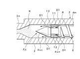
- FIG. 5 shows the behavior of the resin R during the plasticization treatment.
- the screw 4 rotates at a set rotation speed and period. Since the resin R is transferred forward by the rotation of the screw 4, the resin R on the 4 m side of the screw main body portion 4 m is accumulated forward through the screw head portion 4s as shown by arrows D1 ...
- the check valve portion 4 sn moves to the front open position shown in FIG. 5, so that the resin R on the screw main body 4 m side is a check valve. It reaches the front of the conical tip portion 4sc through the resin passage 12 inside the portion 4sn and the resin passage 13 of the conical tip portion 4sc.
- the plasticized resin R is gradually accumulated in the heating cylinder 3 in front of the conical tip portion 4sc, and the screw 4 moves backward with the accumulation.
- step S2 the mold clamping cylinder 27 of the mold clamping device Mc is driven, and the mold clamping force becomes the set molding mold clamping force Pc. Tighten (step S2).
- the injection cylinder 24 of the injection device Mi is driven by switching the valve circuit 37 and controlling the hydraulic pump 36, and the injection process of the resin R is started for the mold 2 (step S3).
- the screw 4 may be advanced by the rated operation, and the speed control for the screw 4 is unnecessary.
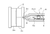
- the plasticized and melted resin R in the heating cylinder 3 is filled into the cavity of the mold 2 through the injection nozzle 3n as shown by the arrow D2 in FIG. 6 (step S4).
- injection pressure Pis injection pressure
- the injection pressure Pis injection pressure
- the injection pressure is maintained (limited) at the limiter pressure Ps.
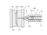
- step S3 the resin R accumulated in front of the screw 4 is injected and filled in the mold 2 and at the same time, the partial reflux injection function unit 5 is used. Due to the function, a predetermined amount of the reflux resin Rm that becomes a part of the resin R is gradually refluxed to the screw main body 4m side behind the screw head portion 4s (step SN). That is, since the screw 4 moves forward at the time of injection, the check valve portion 4sn moves to the rear closed position due to the resin pressure in the front.
- the resin passage 12 inside the check valve portion 4sn is blocked, but the reflux resin Rm, which is a part of the resin R accumulated in front of the screw head portion 4s, is shown in FIG. 6 due to the injection pressure Pis.
- the screw passes through the gap between the outer peripheral surface of the conical tip portion 4sc of the screw head portion 4s and the inner peripheral surface of the heating cylinder 3, and further, the reflux passage 11 ... on the outer peripheral surface of the check valve portion 4sn. It is refluxed to the 4 m side of the main body.
- step S7 when the cavity of the mold 2 is filled with the resin R, the mold 2 is pressed against the resin R, and a mold gap Lm (FIG. 7) is generated between the fixed mold 2c and the movable mold 2m (step S7). ).
- This mold gap Lm is generated based on the molding mold clamping force Pc and the molding injection pressure Pi (injection pressure Pis) set in advance.
- the injection time set in advance elapses from the start of injection, the injection filling of the resin R to the mold 2 is completed, so that the application of the molding injection pressure Pi (injection pressure Pis) is stopped or reduced.
- the substantial injection step is completed, and the reflux action is also terminated accordingly (step S8).
- the resin R Upon completion of the injection step (refluxing action), the resin R is plasticized (step S9).
- a predetermined amount of refluxed resin Rm is mixed on the front side of the screw main body 4 m, that is, a part of the reflux resin Rm of the primary plasticized resin R accumulated in front of the screw 4 is mixed. Since the screw is returned to the 4 m side and mixed, the resin R in which the reflux resin Rm is mixed is subjected to the plasticization treatment. Therefore, even when the resin R having insufficient plasticization is accumulated in front of the screw 4, the replasticization treatment is performed, and the plasticization is further promoted.
- step S10 the resin R is solidified with the passage of time, and the resin R is naturally compressed with the solidification (step S10). That is, since the capacity decreases due to the solidification of the resin R, natural compression is performed by the pressure action due to the elastic return of the mold 2 (particularly the movable mold 2 m) so as to follow the decrease in the capacity.
- the mold clamping cylinder 27 is driven by the switching of the valve circuit 37 and the control of the hydraulic pump 36, the mold is opened by retracting the movable mold 2 m, and the ejector cylinder 31 is opened. It is driven and the molded product adhered to the movable mold 2 m is projected (steps S11 and S12). As a result, the molded product is taken out, and one molding cycle is completed. After that, when the next molding is continued, processing such as mold clamping, injection, and cooling is performed in the same manner (steps S13, S2 ).
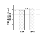
- FIG. 8 shows the variation in the amount of mold displacement when reflux is performed by the injection molding method using the injection molding machine M according to the present embodiment (first embodiment) and the mold displacement when reflux is not performed (without reflux).
- a comparison diagram of the standard deviation values of the amount variation is shown. That is, FIG. 8 shows the variation of the maximum value Lmp of the mold gap Lm in FIG. 7 when 30 molded products are molded. According to this, the standard deviation value without reflux is 4.2 [ ⁇ m], while the standard deviation value with reflux is 3.8 [ ⁇ m], which is about 11 [%]. Improvement was seen. This means that the homogenization of the plasticized resin R was further enhanced, and the yield rate corresponding to the rate of improvement was obtained for the yield rate of the molded product.
- the screw 4 housed in the heating cylinder 3 of the injection device Mi is moved forward.
- the resin R in front of the screw head portion 4s at the front end portion of the screw 4 is injection-filled into the mold 2, and at the same time, a predetermined amount of the reflux resin Rm that becomes a part of the resin R is injected into the reflux passage 11 in the screw head portion 4s. Since the return is made to return to the screw main body 4 m side behind the screw head portion 4s through ..., the yield rate of the final molded product can be significantly increased, and in particular, the conventional limit yield rate can be further increased.
- a mold clamping device Mc capable of spontaneously compressing the resin R at least as the resin R in the mold 2 solidifies.
- a predetermined mold gap Lm is generated between the movable mold 2m and the fixed mold 2c at the time of injection filling, and the molding injection pressure Pi that can be molded into a good product and the molding mold clamping force Pc that can be molded into a good product are obtained and set in advance.
- the mold clamping device Mc is molded by the molding mold clamping force Pc, the molding injection pressure Pi is set as the limiter pressure Ps, and the injection device Mi is driven to inject and fill the mold 2 with resin.
- the injection molding method by the injection molding machine M according to the present invention can be applied to the specific molding mode in which the weighing process does not exist, that is, the specific molding mode which is hardly affected by the state on the injection device Mi side. It can be implemented as an optimum form from the viewpoint of improving the production efficiency and reducing the production cost as described above, and further contributing to the avoidance of resource loss and the avoidance of waste of energy consumption.
- FIG. 9 is an extraction enlarged view of a part of the injection device Mi in the injection molding machine M shown in FIG. 1, that is, the virtual line circle A part, and includes the partial reflux injection function part 5 according to the second embodiment. A part of the injection device Mi is shown.
- the injection device Mi of the second embodiment has the same basic configuration as the injection device Mi provided in the injection molding machine M shown in FIG. 2 of the first embodiment.
- the reflux resin is additionally provided with the reverse rotation control function unit Fc that rotates the screw 4 in the reverse direction to the molding machine controller C shown in FIG. It enables the promotion of reflux and quantitative control of Rm. Therefore, software for realizing the reverse rotation control function unit Fc is stored in the program area 42mp of the internal memory 42m. If such a reverse rotation control function unit Fc is provided when the partial reflux injection function unit 5 is configured, it is not necessary to change the shape of the screw 4 itself. It can be realized, further facilitated implementation, and can be more versatile.
- the reverse rotation control function unit Fc is provided with a reverse rotation setting function unit Fcs for setting the period and rotation speed for rotating the screw 4 in the reverse direction. If such a reverse rotation setting function unit Fcs is provided, the recirculation amount of the recirculation resin Rm can be set by the reverse rotation setting function unit Fcs, so that an arbitrary recirculation amount can be easily set and the mold 2 can be set. On the other hand, it is possible to avoid the influence on the original filling amount of injection filling.
- the screw 4 when setting the period for reverse rotation of the screw 4 and the rotation speed, the screw 4 is moved forward by the molding injection pressure Pi, and the resin R in front of the screw head portion 4s is injected into the mold 2 at the same time.
- a predetermined amount of recirculated resin Rm that becomes a part of the resin R that is, an amount of recirculated resin Rm selected in the range of 10-60 [%] with respect to the capacity of the resin R to be injection-filled in the mold 2 is screwed. It is desirable to set the period and the rotation speed at which the resin passage 12 on the inner side of the head portion 4s can be returned to the screw main body portion 4m side behind the screw head portion 4s.
- FIG. 9 the same parts as those in FIGS. 1 and 2 are designated by the same reference numerals to clarify their configurations and omit detailed description thereof.
- the flowchart shown in FIG. 10 shows specific processing in step SN in the flowchart shown in FIG. 4, and the entire molding procedure is performed according to the flowchart shown in FIG. That is, the injection molding method using the injection molding machine M according to the second embodiment is preset in the same manner as the specific molding mode in the first embodiment, and the specific processing procedure at the time of production is shown in FIG. Except for the processing content of step SN shown, steps S1-S11 are basically the same. Therefore, in the following, only the processing portion according to the second embodiment in the step SN will be described in detail with reference to FIG.
- step S3 in the flowchart shown in FIG. 4 is being performed.
- the injection cylinder 24 of the injection device Mi is driven to start the injection process of the resin R on the mold 2, and the resin R accumulated in front of the screw 4 is filled in the mold 2 (step). S4).
- the screw 4 is controlled to rotate in the reverse direction by the reverse rotation control function unit Fc at a predetermined timing, for example, the timing when the injection process starts or the timing when the predetermined set time has elapsed (step SN1).
- a predetermined timing for example, the timing when the injection process starts or the timing when the predetermined set time has elapsed (step SN1).
- the screw 4 rotates in the reverse direction in the direction of the arrow Drn at the rotation speed set by the reverse rotation setting function unit Fcs.
- the reflux of a part of the resin R existing on the screw head portion 4s side accumulated in front of the screw head portion 4s to the screw main body portion 4m side is promoted (step SN2).
- step SN3 and SN4 the reverse rotation control is stopped.
- a mold gap Lm is generated by injection filling, and when the injection process is completed, solidification of the resin R progresses with the passage of time, and the resin R naturally accompanies this solidification.
- the same processing (behavior) as in the first embodiment is performed, such as compression (steps S5, S6, S7 ).
- the partial reflux injection function unit 5 can perform the same operation (function) as that of the first embodiment. In addition to being able to enjoy the same basic effects as those of the first embodiment, it is possible to enjoy the effects of promoting the reflux action, which is more than that of the first embodiment.
- FIG. 11 shows the relationship between the screw rotation and the recirculation amount when the injection molding method of the injection molding machine M in the second embodiment is used.
- the reflux amount can be arbitrarily controlled such that the screw rotation and the reflux amount can be proportional to each other. can.
- FIG. 12 and 13 show modified examples of the first embodiment and the second embodiment.
- the first embodiment shown in FIG. 2 illustrates the screw head portion 4s using the cylindrical check valve portion 4sn, but the screw head using the ball-shaped check valve portion 4sn as shown in FIG. 12 is illustrated.
- the portion 4s may be used, and various forms of the check valve portion 4sn and the screw head portion 4s can be applied, and the configuration and type thereof are not limited.
- 51 indicates a resin passage.
- FIG. 12 is a modification of the first embodiment, and the basic configuration of the injection molding machine M and the basic processing procedure of the injection molding method are the same as those of the first embodiment described above.
- FIG. 13 is a modified example of the first embodiment or the second embodiment, and the basic configuration of the injection molding machine M and the basic processing procedure of the injection molding method are described in the first embodiment or the second embodiment described above. It will be the same as the embodiment.
- the third embodiment is the injection molding machine M according to the second embodiment of the present invention.
- the first embodiment or the second embodiment including the above-mentioned modification shows the injection molding machine M when the "injection step” and the "recirculation step” are executed at the same time, while the third embodiment shows the "injection step”.
- the injection molding machine M in the case where only the “recirculation step” is independently executed after the completion of the injection molding machine M is shown.
- the molding machine controller C controls the injection device Mi at the time of molding, and the screw 4 in the heating cylinder 3 is rotated to plasticize the resin in the heating cylinder 3 Wi1.
- Wi2 equipped with a control function for sequentially executing the plasticization promotion step Wi3 in which a part of the remaining portion of the resin R plasticized and accumulated after the completion of this injection step Wi2 is refluxed to the rear of the screw head portion 4s as a reflux resin Rm. ing.
- the molding machine controller C has a function of refluxing the plasticized and accumulated resin R in the plasticization promotion step Wi3, that is, a part of the resin R accumulated in front of the screw head portion 4s (reflux resin).
- Software for realizing control functions is stored.
- the pressurization control function is a reflux method in which the resin R flows backward by performing pressurization control to increase the forward pressing force on the screw 4.
- the pressurization control function the molded product in the mold 2 (after the gate seal) or after the cooling step after the injection step Wi2 is completed, such as after the resin R in the mold 2 is sufficiently solidified (after the gate seal). In the solidified state where the resin) is not affected, the pressure of the resin R accumulated in front of the screw head portion 4s can be increased to a size required for reflux.
- the screw head portion 4s may be provided with a slight recirculation passage that does not cause recirculation depending on the molding injection pressure Pi, or may be provided with a recirculation passage having an opening / closing function. Therefore, the amount of resin to be refluxed (the amount of refluxed resin) can be relatively easily implemented by increasing or decreasing the pressing force or setting the pressurizing time.
- the reverse rotation control function is a reflux method in which the resin R is returned to the rear by rotating the screw 4 in the reverse direction, and basically functions in combination with the above-mentioned pressurization control function.
- the amount of recirculation can be adjusted by controlling the screw 4 to rotate in the reverse direction. Therefore, the amount of recirculated resin can be set by selecting conditions such as the period for reverse rotation and the rotation speed, which can be more easily carried out, and can be arbitrarily changed by changing the period for reverse rotation of the screw 4 and the rotation speed. The amount of recirculation can be set easily and accurately. It is also possible to select and use either the pressurization control function or the reverse rotation control function.
- the injection pressure which is the injection condition on the injection device Mi side
- the injection pressure can be set based on the ability (driving force) of the injection device Mi.
- the mold clamping force which is the mold clamping condition on the mold clamping device Mc side
- the mold clamping force can be set based on the capacity (driving force) of the mold clamping device Mc.
- the molding injection pressure Pi to be used at the time of production is obtained by performing the optimization processing for the initially set injection pressure
- the molding mold clamping force Pc to be used at the time of production is obtained by performing the optimization processing for the initially set mold clamping force.
- the mold clamping force and injection pressure can be optimized as follows. First, trial molding is performed using the initially set mold clamping force and injection pressure. When the mold clamping force is set to a large value, burrs do not occur, and sink marks, warpage, and degassing conditions tend to be defective or defective.
- the size of the mold gap Lm between the fixed mold 2c and the movable mold 2 m is not shown. It is acquired by a mold gap sensor (reflection type optical sensor or the like), displayed on the waveform display unit on the screen of the display 42d, and the quality of the molded product is observed.
- a mold gap sensor reflection type optical sensor or the like
- FIG. 14 shows change data of the mold gap Lm displayed on this waveform display unit.
- FIG. 14 shows a range (band) of the maximum value and the minimum value in 30 molding shots.
- the basic change is that the mold 2 starts to open at the to time point after the start of injection, and the maximum mold gap Lmp occurs at the tp time point. After that, it gradually changes in the closing direction, and finally settles in the remaining mold gap Lme and stabilizes.
- the above-mentioned predetermined mold gap Lm (about 0.03-0.30 [mm]) is generated between the mobile mold 2m and the fixed mold 2c at the time of injection filling, and good product molding becomes possible.
- the molding injection pressure Pi can be set on the condition that Specifically, the injection pressure can be appropriately changed to select a size before the resin R does not normally fill the mold 2. Further, the obtained molding injection pressure Pi is set as the limiter pressure Ps with respect to the injection pressure at the time of production. On the other hand, by repeating these trial moldings by changing the conditions, the mold clamping force satisfying the above-mentioned conditions can be selected.
- the selected mold clamping force is set as the molding mold clamping force Pc when mold clamping is performed by the mold 2 at the time of production.
- the magnitudes of the mold clamping force and the injection pressure may be arbitrarily set by the operator, or may be automatically or semi-automatically obtained while using the auto-tuning function provided in the injection molding machine M and the like.
- a plasticizing treatment is performed on the resin (material) (step S21).
- the step of performing this plasticizing process is the plasticizing step Wi1 shown in FIG.
- the metering motor 25 of the injection device Mi is rotationally driven by the control of the hydraulic pump 36 and the switching of the valve circuit 37.
- the screw 4 shown in FIG. 9 rotates forward over the set rotation speed and period. Since the resin R is transferred forward by the forward rotation of the screw 4, the resin R on the side of the screw main body 4 m is accumulated forward through the screw head portion 4s while being plasticized. At this time, the resin R moves forward from the screw body 4 m side, so that the check valve portion 4sn moves to the front open position. Therefore, the resin R on the screw body 4 m side is the check valve portion 4sn. It reaches the front of the conical tip 4sc through the inner resin passage 12 and the resin passage 13 of the conical tip 4sc. As a result, the plasticized resin R is gradually accumulated as the plasticized resin R in the heating cylinder 3 in front of the conical tip portion 4sc, and the screw 4 moves backward with this accumulation. ..
- the specific molding mode does not require a weighing step for accurately measuring the resin R as in the molding method using a general molding mode. That is, since the injection treatment in the specific molding mode only needs to perform the injection operation until the cavity is filled with the resin R, it is sufficient to carry out a large amount of the resin R in the plasticizing step. In other words, the weighing operation in a general weighing process is performed, but the weighing control for obtaining an accurate weighing value becomes unnecessary.
- step S22 by controlling the hydraulic pump 36 and switching the valve circuit 37, the mold clamping cylinder 27 of the mold clamping device Mc is driven, and the movable mold 2 m is moved in the mold closing direction (step S22).
- This operation is the mold closing step Wc1 shown in FIG.
- the mold clamping process is executed for the mold 2 so that the mold clamping force becomes the set molding mold clamping force Pc (step S23).
- This operation is the mold clamping step Wc2 shown in FIG. Further, FIG. 18 shows this state.
- the injection cylinder 24 of the injection device Mi is driven by switching the valve circuit 37 and controlling the hydraulic pump 36, and the injection process of the resin R is started for the mold 2 (step S24).
- the injection step Wi2 shown in FIG. 15 is performed.
- the screw 4 may be advanced by the rated operation, and speed control and pressure control for the screw 4 are unnecessary.
- the plasticized and melted resin R in the heating cylinder 3 is filled in the cavity of the mold 2 through the injection nozzle 3n (step S25).
- the injection pressure increases with the filling of the resin R (step S26).
- control for maintaining the limiter pressure Ps that is, control for preventing overshoot is performed, and the injection pressure is maintained (limited) to the limiter pressure Ps (step). S27). Therefore, in the injection operation, substantial one-pressure control is performed.
- step S28 the natural gap generation step Wc3 shown in FIG. 15 proceeds.
- This mold gap Lm is generated based on the molding mold clamping force Pc and the molding injection pressure Pi set in advance. This state is shown in FIG. The figure shows an image in which the maximum mold gap Lmp is generated as the mold gap Lm.
- the mold 2 side shifts to the cooling process Wc4 in which the cooling process is performed for the preset cooling time.
- the resin R is solidified with the passage of time, and the resin R is naturally compressed with the solidification (steps S30 and S31). That is, since the capacity decreases due to the solidification of the resin R, natural compression is performed by the pressure action due to the elastic return of the mold 2 (particularly the movable mold 2 m) so as to follow the decrease in the capacity.
- FIG. The figure shows an image in which the residual mold gap Lme is generated as the mold gap Lm.
- the plasticization promotion step Wi3 shown in FIG. 15 is executed at a preset timing (step S32).
- the auxiliary plasticization treatment for the resin (material) is performed for the predetermined auxiliary plasticization time T1 set in advance (step S121).
- the reason for this is that at the end stage of the injection process, the amount of the thermoplastic accumulation resin R accumulated in front of the screw 4 becomes small, so that the amount of recirculation is secured by performing the auxiliary plasticization treatment for the auxiliary plasticization time T1.
- the auxiliary plasticizing treatment may be an amount (total amount) in the plasticizing step Wi1 or may be a part thereof.
- the auxiliary plasticization time T1 to be set may be set according to a predetermined auxiliary plasticization position with respect to the screw 4.
- the resin R in the mold 2 (including the gate and the like) is solidified to some extent, and even if a high forward pressure is applied to the screw 4 by the pressurizing control function, the front is forwarded. It is possible to set a length at which the resin R does not flow, or a length that does not affect the resin R (molded product) in the mold 2 even if the screw 4 is controlled to rotate in the reverse direction by the reverse rotation control function. desirable.
- the substantial plasticization promotion step Wi3 is performed. That is, the reverse rotation control function and / or the pressurization control function described above for the screw 3 is executed (step S122).
- the pressurization control function drives the injection cylinder 24 to control the screw 4 to apply a forward pressing force.
- the pressing force at this time is set higher than the molding injection pressure Pi (limiter pressure Ps), so that it is possible to return to the rear.
- the start of applying the pressing force is the timing at which the resin R does not flow forward even if a high pressing force is applied forward, that is, at least by starting the cooling step Wc4 in the mold 2, the gate seal or the like. Is performed, and the molded product (resin R) is not affected.
- the plasticized and accumulated resin R is refluxed to the rear of the screw head portion 4s through the gap between the screw head portion 4s and the heating cylinder 3. Then, the reflux resin Rm that has flowed back to the rear of the screw head portion 4s is added to and mixed with the resin R on the screw main body portion 4m side. After that, when the plasticization promotion processing time T2 has elapsed, the plasticization promotion control (pressurization control) is stopped (steps S123 and S124). That is, the plasticization promotion step Wi3 using the pressurization control function is completed.
- the plasticization promotion treatment time T2 and the pressing pressure are preferably higher than the completion of the cooling treatment and the injection pressure Pi from the viewpoint of ensuring the production efficiency and the yield rate.
- the screw head portion 4s be provided with a slight reflux passage or a reflux passage with an opening / closing function in which reflux does not occur depending on the molding injection pressure Pi.
- step S122 when the reverse rotation control function is performed, in addition to the pressurization control function, the measuring motor 25 is driven and the screw 4 is controlled to rotate in the reverse direction at a preset rotation speed (step S122).
- the reflux of the plasticized storage resin R through the screw head portion 4s, which is a backflow, to the rear of the screw head portion 4s is promoted.
- the reflux resin Rm that has flowed back through the screw head portion 4s is added to and mixed with the resin R on the screw main body portion 4m side behind the screw head portion 4s.
- the plasticization promotion control reverse rotation control
- FIG. 20 shows a state in which the screw 4 is advanced and the target return amount is returned to the rear of the screw head portion 4s.
- step S33 the plasticization process by the plasticization step Wi1 is performed (step S33).
- the reflux resin Rm is mixed on the front side of the screw main body 4 m, that is, a part of the resin R that has been subjected to the primary plasticization treatment accumulated in front of the screw 4 is used as the reflux resin Rm and the screw main body 4 m. Since it is returned to the side and mixed, the resin R in which the reflux resin Rm is mixed is subjected to the plasticization treatment. Therefore, even when the insufficiently plasticized resin R and the refluxed resin Rm are accumulated in front of the screw 4, the replasticization treatment is performed, and the plasticization is further promoted.
- step S34 the mold opening step Wc5 shown in FIG.
- step S35 the molded product take-out step Wc6 shown in FIG.
- each process such as mold closing, mold clamping, injection, and cooling is performed in the same manner. It is performed sequentially (steps S36, S22 ).
- FIG. 14 shows the relationship between the time t [t] and the mold gap Lm [mm] in the injection step Wi2 by the injection molding method using the injection molding machine M according to the third embodiment, and in particular, 30 molded products are shown.
- the change data of each mold gap Lm ... During molding that is, the range (band) of the maximum value and the minimum value in 30 molding shots is shown, and the band Bi shown by the solid line corresponds to the third embodiment.
- the band Br shown by the virtual line indicates the case without recirculation, so to speak. According to this, when there is reflux, the variation of the mold gap Lm ...
- the relationship between the reverse rotation of the screw and the amount of recirculation by the injection molding method using the injection molding machine M according to the third embodiment is the same as in FIG. 11 described above.
- the recirculation of the resin R can be promoted and quantitatively controlled, so that the reverse rotation amount of the screw and the recirculation amount can be made proportional to each other. Can be controlled arbitrarily.
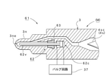
- This modification uses an injection molding machine M (injection device Mi) provided with the shut-off nozzle 61 shown in FIG. 22.
- the exemplary shut-off nozzle 61 has a known structure, in FIG. 22, 37 is the valve circuit shown in FIG. 1, and 62 is the nozzle port at the tip of the injection nozzle 3n due to the switching operation of the valve circuit 37.
- a shut-off valve that opens and closes 3ne, 62v is a shaft-shaped valve body, 62c is a drive cylinder that moves the valve body 62v forward and backward in the opening direction (rear) or closing direction (front), and 63 is a resin passage.
- the same parts as those in FIG. 9 described above are designated by the same reference numerals to clarify their configurations and omit detailed description thereof.
- the nozzle opening 3ne can be shut off as needed, so that the plasticization promotion step Wi3 is also performed during the cooling step Wc4, the mold opening step Wc5, and the molded product take-out step Wc6. It can be performed. As a result, it becomes possible to carry out a sufficient plasticization promotion treatment in terms of time, and the injection molding method using the injection molding machine M according to the present invention can be carried out more reliably and satisfactorily.
- the shut-off nozzle 61 can be replaced by various nozzle structures having the same function such as a valve nozzle.
- FIG. 21 is a flowchart showing a processing procedure of the injection molding method according to the modified embodiment, and specifically shows step S32 in the flowchart shown in FIG.
- the modification is basically performed based on the same processing procedure as the flowchart shown in FIG. 16, except for the processing content of step S32.
- the auxiliary plasticization processing part for performing the auxiliary plasticization treatment and the plasticization promotion processing part for performing the plasticization promotion treatment in FIG. 17 described above are set in advance.
- the auxiliary plasticization processing part sets the unit time for performing the auxiliary plasticization treatment as a predetermined auxiliary plasticization time T1e
- the plasticization promotion processing part sets the unit time for performing the plasticization promotion treatment as a predetermined unit time. Is set as the plasticization promotion processing time T2e.
- step S29 shown in FIG. 16 (FIG. 21) is completed.
- the shut-off valve 62 is driven and controlled, and the valve 62 is switched to the closed side (step S-SC). That is, in this case, the valve body 62v advances and the nozzle port 3ne is shut off.
- step S201 the auxiliary plasticization processing part in which the auxiliary plasticization processing in FIG. 17 described above is performed over the auxiliary plasticization time T1e is executed.
- the plasticization promotion processing part in which the plasticization promotion treatment is performed over the plasticization promotion processing time T2e is subsequently executed (steps S202 and S203).
- the combination step of the auxiliary plasticization processing part and the plasticization promotion processing part is repeated for a preset number of times N (steps S204, S201 ).
- the processing time of the plasticization promotion step Wi3 is simply set. Not only can it be lengthened, but it is also possible to repeat such a combination process multiple times (N times). The number of repetitions can be set arbitrarily.
- FIG. 21 illustrates the case where the combination step is executed a plurality of times (N times), it can be repeated within the allowable time of the plasticization promotion step Wi3.
- the cooling time when the cooling time is relatively long, for example, as in a large molded product, the cooling time can be effectively utilized by performing such repeated processing.
- the plasticization treatment for the resin R can be performed more uniformly and precisely, which can contribute to further quality improvement and yield rate improvement of the molded product.
- step S33 the plasticization process by the plasticization step Wi1 is performed. Further, the shut-off valve 62 is driven and controlled at a predetermined timing, and the valve 62 is switched to the open side (step S-SO). The position on the open side is the position shown in FIG. After that, when the next molding is continued, each process (each step) such as mold closing, mold clamping, injection, and cooling is performed in the same manner (steps S36, S22, S23 ... (See FIG. 16)). ..
- the screw 4 in the heating cylinder 3 is rotated during molding to form the inside of the heating cylinder 3.
- a part of the remaining portion of the plasticized accumulated resin R is used as a reflux resin Rm to the rear of the screw head portion 4s after the completion of the injection step Wi2.
- the molding method can be provided as a feasible injection molding machine. As a result, it becomes possible to improve the production efficiency and reduce the production cost in the production of large-sized molded products and special resin molded products, and it is possible to effectively contribute to avoiding the occurrence of resource loss and avoiding waste of energy consumption.
- the mold clamping device Mc a mold clamping device that enables natural compression of the resin at least as the resin in the mold 2 solidifies is used, and a predetermined mold is previously placed between the movable mold 2m and the fixed mold 2c at the time of injection filling.
- a mold gap Lm is generated, and the molding injection pressure Pi capable of forming a good product and the molding mold clamping force Pc capable of forming a good product are obtained and set, and at the time of molding, the mold clamping device Mc is molded by the molding mold clamping force Pc.
- the injection molding machine according to the present invention can be applied to a specific molding mode in which there is no weighing process that is hardly affected by the state of the injection device Mi, and thus the production efficiency. It can be implemented as an optimum form from the viewpoint of contributing to the avoidance of resource loss and the avoidance of waste of energy consumption.
- the predetermined amount of reflux resin Rm to be refluxed is preferably selected in the range of 10-60 [%] with respect to the capacity of the resin R to be injected and filled in the mold 2, but the type of the resin R and the molded product. Any range can be selected according to the type of plastic.
- the partial reflux injection function portion 5 when the partial reflux injection function portion 5 is configured, the configuration in which at least one reflux passage 11 for refluxing the reflux resin Rm is provided in the screw head portion 4s is illustrated, but the outer diameter of the screw head portion 4s is specified. It is a concept included in the reflux passage 11 when it is selected to be small, the inner diameter of the heating cylinder 3 is increased, or a part of the inner wall of the heating cylinder 3 is grooved.
- the injection pressure additional setting function unit Fs is not an indispensable element, and for example, depending on the form of the reflux passage 11, it is not always necessary to provide the injection pressure additional setting function unit Fs.
- a type that passes through the inner side of the screw head portion 4s a type that passes through the outer peripheral portion side of the screw head portion 4s, and an inner side of the screw head portion 4s. And either of the forms in which both the screw head portion 4s and the outer peripheral portion side of the screw head portion 4s are passed through may be used.
- the injection molding machine M may be a hydraulic injection molding machine or an electric injection molding machine, and the drive method thereof does not matter.
- the mold clamping device Mc a mold clamping device capable of spontaneously compressing the resin at least as the resin in the mold 2 solidifies is used, and the movable mold 2 m and the fixed mold 2c are used in advance at the time of injection filling. A predetermined mold gap Lm is generated between them, and the molding injection pressure Pi that can be molded into a good product and the molding mold clamping force Pc that can be molded into a good product are obtained and set.
- a specific molding mode which is a molding method for mold clamping and setting the molding injection pressure Pi as the limiter pressure Ps, but for an injection molding machine M or an injection molding method that uses a general molding mode. Is also applicable.
- the injection molding machine M may be a hydraulic injection molding machine or an electric injection molding machine, and the drive method thereof does not matter.
- the pressurization control function and the reverse rotation control function are exemplified as the functions for refluxing the thermoplastic storage resin R, but the case where the thermoplastic storage resin R is refluxed by other functions is not excluded.
- the specific methods for functioning the pressurization control function and the reverse rotation control function are not limited to the exemplary methods, and other methods capable of similarly functioning may be used.
- the present invention can be used in various injection molding machines that inject and fill a mold compacted by a predetermined mold clamping force with a resin by a predetermined injection pressure to perform molding.
Landscapes
- Engineering & Computer Science (AREA)
- Manufacturing & Machinery (AREA)
- Mechanical Engineering (AREA)
- Injection Moulding Of Plastics Or The Like (AREA)
Abstract
Description
Claims (14)
- 固定型と可動型からなる金型を所定の型締力により型締する型締装置と、型締された金型に対して所定の射出圧力により樹脂を射出充填する射出装置と、前記型締装置及び前記射出装置に対する制御を行う成形機コントローラとを備える射出成形機において、前記射出装置の加熱筒に収容したスクリュを前進移動させることにより当該スクリュの前端部におけるスクリュヘッド部の前方の樹脂を金型に射出充填し、かつ当該樹脂の一部となる所定量の樹脂を、還流樹脂として前記スクリュヘッド部の後方におけるスクリュ本体部側に還流させるに際し、前記スクリュヘッド部の前方の樹脂を金型に射出充填すると同時に、前記所定量の樹脂を、還流樹脂としてスクリュヘッド部の内部側及び/又はスクリュヘッド部の外周部側を通して当該スクリュヘッド部の後方におけるスクリュ本体部側に還流させる一部還流射出機能部を設けたことを特徴とする射出成形機。
- 前記所定量は、前記金型に射出充填する樹脂の容量に対して、10-60〔%〕の範囲に選定することを特徴とする請求項1記載の射出成形機。
- 前記一部還流射出機能部は、前記スクリュヘッド部に、樹脂が還流する少なくとも一つの還流通路を設けて構成することを特徴とする請求項1又は2記載の射出成形機。
- 前記一部還流射出機能部には、成形時の射出圧力を、前記樹脂が還流しないときの射出圧力に対して所定の大きさだけ高く設定する射出圧力追加設定機能部を設けることを特徴とする請求項3記載の射出成形機。
- 前記一部還流射出機能部は、前記スクリュを逆回転させる逆回転制御機能部を設けて構成することを特徴とする請求項1又は2記載の射出成形機。
- 前記逆回転制御機能部には、前記スクリュを逆回転させる期間及び回転速度の逆回転設定機能部を設けることを特徴とする請求項5記載の射出成形機。
- 前記型締装置として少なくとも金型内の樹脂の固化に伴って樹脂の自然圧縮が可能となる型締装置を使用するとともに、前記成形機コントローラは、予め、射出充填時に可動型と固定型間に所定の型隙間が生じ、かつ良品成形可能な射出圧力(以下、成形射出圧力)と良品成形可能な型締力(以下、成形型締力)を求めて設定し、成形時に、前記成形型締力により型締装置を型締し、かつ前記成形射出圧力をリミッタ圧力として設定することにより、前記射出装置を駆動して金型に対する樹脂の射出充填を行う制御機能を備えることを特徴とする請求項1記載の射出成形機。
- 固定型と可動型からなる金型を所定の型締力により型締する型締装置と、型締された金型に対して所定の射出圧力により樹脂を射出充填する射出装置と、前記型締装置及び前記射出装置に対する制御を行う成形機コントローラとを備える射出成形機において、前記射出装置の加熱筒に収容したスクリュを前進移動させることにより当該スクリュの前端部におけるスクリュヘッド部の前方の樹脂を金型に射出充填し、かつ当該樹脂の一部となる所定量の樹脂を、還流樹脂として前記スクリュヘッド部の後方におけるスクリュ本体部側に還流させるに際し、加熱筒内のスクリュを回転させることにより当該加熱筒内の樹脂を可塑化処理する可塑化工程,この可塑化工程の終了後に前記スクリュを前進移動させることにより当該スクリュにおけるスクリュヘッド部の前方に可塑化蓄積された樹脂の一部を前記金型に対して射出充填する射出工程,この射出工程の終了後に前記樹脂の残部の一部を、還流樹脂として前記スクリュヘッド部の後方へ還流させる可塑化促進工程,を順次実行する成形機コントローラを備えることを特徴とする射出成形機。
- 前記射出装置は、シャットオフノズル又はバルブノズルを備えることを特徴とする請求項8記載の射出成形機。
- 前記型締装置として少なくとも金型内の樹脂の固化に伴って樹脂の自然圧縮が可能となる型締装置を使用するとともに、前記成形機コントローラは、予め、射出充填時に可動型と固定型間に所定の型隙間が生じ、かつ良品成形可能な射出圧力(以下、成形射出圧力)と良品成形可能な型締力(以下、成形型締力)を求めて設定し、成形時に、前記成形型締力により型締装置を型締し、かつ前記成形射出圧力をリミッタ圧力として設定することにより、前記射出装置を駆動して金型に対する樹脂の射出充填を行う制御機能を備えることを特徴とする請求項8記載の射出成形機。
- 前記可塑化促進工程では、前記スクリュに対する前方への加圧制御機能により前記可塑化蓄積樹脂を還流させることを特徴とする請求項8記載の射出成形機。
- 前記可塑化促進工程では、前記スクリュに対する逆回転制御機能により前記可塑化蓄積樹脂を還流させることを特徴とする請求項8記載の射出成形機。
- 前記可塑化促進工程では、実質的な可塑化促進処理を実行する前に、前記還流樹脂の量を確保する補助可塑化処理を行うことを特徴とする請求項8記載の射出成形機。
- 前記可塑化促進工程では、前記補助可塑化処理を行う補助可塑化処理パートと可塑化促進処理を行う可塑化促進処理パートを設定し、この設定に基づく前記補助可塑化処理パートと前記可塑化促進処理パートの組み合わせ工程を、予め設定した回数N,又は前記可塑化促進工程の許容される時間内において、繰り返して行うことを特徴とする請求項13記載の射出成形機。
Priority Applications (3)
| Application Number | Priority Date | Filing Date | Title |
|---|---|---|---|
| US18/026,078 US12583156B2 (en) | 2020-09-14 | 2021-09-14 | Injection molding machine |
| EP21866914.1A EP4212307A4 (en) | 2020-09-14 | 2021-09-14 | INJECTION MOLDING MACHINE |
| CN202180062591.3A CN116113530A (zh) | 2020-09-14 | 2021-09-14 | 注射成型机 |
Applications Claiming Priority (4)
| Application Number | Priority Date | Filing Date | Title |
|---|---|---|---|
| JP2020153482A JP7165167B2 (ja) | 2020-09-14 | 2020-09-14 | 射出成形機及び射出成形方法 |
| JP2020-153482 | 2020-09-14 | ||
| JP2020167970A JP7196141B2 (ja) | 2020-10-02 | 2020-10-02 | 射出成形方法及び射出成形機 |
| JP2020-167970 | 2020-10-02 |
Publications (1)
| Publication Number | Publication Date |
|---|---|
| WO2022054958A1 true WO2022054958A1 (ja) | 2022-03-17 |
Family
ID=80631722
Family Applications (1)
| Application Number | Title | Priority Date | Filing Date |
|---|---|---|---|
| PCT/JP2021/033653 Ceased WO2022054958A1 (ja) | 2020-09-14 | 2021-09-14 | 射出成形機 |
Country Status (4)
| Country | Link |
|---|---|
| US (1) | US12583156B2 (ja) |
| EP (1) | EP4212307A4 (ja) |
| CN (1) | CN116113530A (ja) |
| WO (1) | WO2022054958A1 (ja) |
Citations (5)
| Publication number | Priority date | Publication date | Assignee | Title |
|---|---|---|---|---|
| JPS60135224A (ja) * | 1983-12-23 | 1985-07-18 | Fanuc Ltd | 射出成形機における混練方法 |
| JPH0336819U (ja) * | 1989-08-23 | 1991-04-10 | ||
| JPH05138703A (ja) * | 1991-11-20 | 1993-06-08 | Meiki Co Ltd | 射出成形機の逆流防止弁 |
| JP2010173183A (ja) * | 2009-01-29 | 2010-08-12 | Fanuc Ltd | 射出成形機の制御装置 |
| WO2011161899A1 (ja) | 2010-06-25 | 2011-12-29 | 日精樹脂工業株式会社 | 射出成形機の成形方法 |
Family Cites Families (5)
| Publication number | Priority date | Publication date | Assignee | Title |
|---|---|---|---|---|
| JP4264427B2 (ja) * | 2005-05-30 | 2009-05-20 | 日精樹脂工業株式会社 | 射出成形機の計量方法 |
| JP4137975B2 (ja) * | 2006-12-26 | 2008-08-20 | ファナック株式会社 | 射出成形機、及び射出成形機における逆回転工程の制御条件調整方法 |
| WO2017011530A1 (en) * | 2015-07-15 | 2017-01-19 | iMFLUX Inc. | Injection molding with a leaking check ring |
| CN107787270B (zh) * | 2015-07-20 | 2020-08-25 | 克劳斯玛菲科技有限公司 | 用于运行注塑成型机的方法 |
| JP2025135224A (ja) | 2024-03-05 | 2025-09-18 | ニチコン株式会社 | 機器設置用基礎ブロック |
-
2021
- 2021-09-14 EP EP21866914.1A patent/EP4212307A4/en active Pending
- 2021-09-14 CN CN202180062591.3A patent/CN116113530A/zh active Pending
- 2021-09-14 WO PCT/JP2021/033653 patent/WO2022054958A1/ja not_active Ceased
- 2021-09-14 US US18/026,078 patent/US12583156B2/en active Active
Patent Citations (5)
| Publication number | Priority date | Publication date | Assignee | Title |
|---|---|---|---|---|
| JPS60135224A (ja) * | 1983-12-23 | 1985-07-18 | Fanuc Ltd | 射出成形機における混練方法 |
| JPH0336819U (ja) * | 1989-08-23 | 1991-04-10 | ||
| JPH05138703A (ja) * | 1991-11-20 | 1993-06-08 | Meiki Co Ltd | 射出成形機の逆流防止弁 |
| JP2010173183A (ja) * | 2009-01-29 | 2010-08-12 | Fanuc Ltd | 射出成形機の制御装置 |
| WO2011161899A1 (ja) | 2010-06-25 | 2011-12-29 | 日精樹脂工業株式会社 | 射出成形機の成形方法 |
Non-Patent Citations (1)
| Title |
|---|
| See also references of EP4212307A4 |
Also Published As
| Publication number | Publication date |
|---|---|
| US12583156B2 (en) | 2026-03-24 |
| EP4212307A4 (en) | 2024-10-30 |
| CN116113530A (zh) | 2023-05-12 |
| US20230364841A1 (en) | 2023-11-16 |
| EP4212307A1 (en) | 2023-07-19 |
Similar Documents
| Publication | Publication Date | Title |
|---|---|---|
| JP5801924B2 (ja) | 射出成形機の成形方法 | |
| JP5290388B2 (ja) | 薄肉成形品の成形方法 | |
| US6488490B1 (en) | Thermoplastic resin injection molding machine with the injecting unit including a rotary pump and torque limiter | |
| US3773451A (en) | Screw-type injection-molding machine | |
| CN103358497A (zh) | 注射成型机 | |
| JP5022734B2 (ja) | 射出成形機 | |
| CN100482444C (zh) | 注射成型机的控制器 | |
| JP7165167B2 (ja) | 射出成形機及び射出成形方法 | |
| JP7196141B2 (ja) | 射出成形方法及び射出成形機 | |
| JP6868654B2 (ja) | 射出成形方法及び射出成形機 | |
| CN121175170A (zh) | 注射成型机的塑化控制方法和装置 | |
| JP4022157B2 (ja) | プリプラ式射出成形機の制御方法 | |
| CN116113530A (zh) | 注射成型机 | |
| JP2000263607A (ja) | 射出成形機および射出成形方法 | |
| JP6429923B2 (ja) | 可塑化装置とプランジャ式射出装置とからなる射出装置の運転方法 | |
| JP3232550B2 (ja) | 射出圧縮成形における型締圧力の制御方法 | |
| JP3232547B2 (ja) | 射出圧縮成形方法 | |
| CN121871056A (zh) | 注射成型机的塑化控制方法和装置 | |
| JP2008207562A (ja) | 多数回射出成形方法 | |
| JP2022089627A (ja) | プリプラ式射出成形機及びその成形方法 | |
| KR101394846B1 (ko) | 박육 성형품의 성형 방법 | |
| WO2022102643A1 (ja) | プリプラ式射出成形機の成形方法 | |
| JP2022077118A (ja) | プリプラ式射出成形機の成形方法 | |
| CN119820776A (zh) | 注射成型机 | |
| JP2012143927A (ja) | 射出成形機の成形方法 |
Legal Events
| Date | Code | Title | Description |
|---|---|---|---|
| 121 | Ep: the epo has been informed by wipo that ep was designated in this application |
Ref document number: 21866914 Country of ref document: EP Kind code of ref document: A1 |
|
| WWE | Wipo information: entry into national phase |
Ref document number: 2021866914 Country of ref document: EP |
|
| NENP | Non-entry into the national phase |
Ref country code: DE |
|
| ENP | Entry into the national phase |
Ref document number: 2021866914 Country of ref document: EP Effective date: 20230414 |
|
| WWG | Wipo information: grant in national office |
Ref document number: 18026078 Country of ref document: US |