WO2022059092A1 - レンズ部品及び信号表示灯 - Google Patents
レンズ部品及び信号表示灯 Download PDFInfo
- Publication number
- WO2022059092A1 WO2022059092A1 PCT/JP2020/035077 JP2020035077W WO2022059092A1 WO 2022059092 A1 WO2022059092 A1 WO 2022059092A1 JP 2020035077 W JP2020035077 W JP 2020035077W WO 2022059092 A1 WO2022059092 A1 WO 2022059092A1
- Authority
- WO
- WIPO (PCT)
- Prior art keywords
- light
- angle range
- radiation
- incident
- radiation angle
- Prior art date
- Legal status (The legal status is an assumption and is not a legal conclusion. Google has not performed a legal analysis and makes no representation as to the accuracy of the status listed.)
- Ceased
Links
Images









Classifications
-
- F—MECHANICAL ENGINEERING; LIGHTING; HEATING; WEAPONS; BLASTING
- F21—LIGHTING
- F21K—NON-ELECTRIC LIGHT SOURCES USING LUMINESCENCE; LIGHT SOURCES USING ELECTROCHEMILUMINESCENCE; LIGHT SOURCES USING CHARGES OF COMBUSTIBLE MATERIAL; LIGHT SOURCES USING SEMICONDUCTOR DEVICES AS LIGHT-GENERATING ELEMENTS; LIGHT SOURCES NOT OTHERWISE PROVIDED FOR
- F21K9/00—Light sources using semiconductor devices as light-generating elements, e.g. using light-emitting diodes [LED] or lasers
- F21K9/60—Optical arrangements integrated in the light source, e.g. for improving the colour rendering index or the light extraction
- F21K9/69—Details of refractors forming part of the light source
-
- F—MECHANICAL ENGINEERING; LIGHTING; HEATING; WEAPONS; BLASTING
- F21—LIGHTING
- F21V—FUNCTIONAL FEATURES OR DETAILS OF LIGHTING DEVICES OR SYSTEMS THEREOF; STRUCTURAL COMBINATIONS OF LIGHTING DEVICES WITH OTHER ARTICLES, NOT OTHERWISE PROVIDED FOR
- F21V5/00—Refractors for light sources
- F21V5/04—Refractors for light sources of lens shape
- F21V5/043—Refractors for light sources of lens shape the lens having cylindrical faces, e.g. rod lenses, toric lenses
-
- F—MECHANICAL ENGINEERING; LIGHTING; HEATING; WEAPONS; BLASTING
- F21—LIGHTING
- F21V—FUNCTIONAL FEATURES OR DETAILS OF LIGHTING DEVICES OR SYSTEMS THEREOF; STRUCTURAL COMBINATIONS OF LIGHTING DEVICES WITH OTHER ARTICLES, NOT OTHERWISE PROVIDED FOR
- F21V33/00—Structural combinations of lighting devices with other articles, not otherwise provided for
-
- F—MECHANICAL ENGINEERING; LIGHTING; HEATING; WEAPONS; BLASTING
- F21—LIGHTING
- F21V—FUNCTIONAL FEATURES OR DETAILS OF LIGHTING DEVICES OR SYSTEMS THEREOF; STRUCTURAL COMBINATIONS OF LIGHTING DEVICES WITH OTHER ARTICLES, NOT OTHERWISE PROVIDED FOR
- F21V5/00—Refractors for light sources
- F21V5/02—Refractors for light sources of prismatic shape
-
- F—MECHANICAL ENGINEERING; LIGHTING; HEATING; WEAPONS; BLASTING
- F21—LIGHTING
- F21V—FUNCTIONAL FEATURES OR DETAILS OF LIGHTING DEVICES OR SYSTEMS THEREOF; STRUCTURAL COMBINATIONS OF LIGHTING DEVICES WITH OTHER ARTICLES, NOT OTHERWISE PROVIDED FOR
- F21V5/00—Refractors for light sources
- F21V5/04—Refractors for light sources of lens shape
-
- F—MECHANICAL ENGINEERING; LIGHTING; HEATING; WEAPONS; BLASTING
- F21—LIGHTING
- F21V—FUNCTIONAL FEATURES OR DETAILS OF LIGHTING DEVICES OR SYSTEMS THEREOF; STRUCTURAL COMBINATIONS OF LIGHTING DEVICES WITH OTHER ARTICLES, NOT OTHERWISE PROVIDED FOR
- F21V5/00—Refractors for light sources
- F21V5/04—Refractors for light sources of lens shape
- F21V5/046—Refractors for light sources of lens shape the lens having a rotationally symmetrical shape about an axis for transmitting light in a direction mainly perpendicular to this axis, e.g. ring or annular lens with light source disposed inside the ring
-
- F—MECHANICAL ENGINEERING; LIGHTING; HEATING; WEAPONS; BLASTING
- F21—LIGHTING
- F21V—FUNCTIONAL FEATURES OR DETAILS OF LIGHTING DEVICES OR SYSTEMS THEREOF; STRUCTURAL COMBINATIONS OF LIGHTING DEVICES WITH OTHER ARTICLES, NOT OTHERWISE PROVIDED FOR
- F21V7/00—Reflectors for light sources
- F21V7/0091—Reflectors for light sources using total internal reflection
-
- F—MECHANICAL ENGINEERING; LIGHTING; HEATING; WEAPONS; BLASTING
- F21—LIGHTING
- F21V—FUNCTIONAL FEATURES OR DETAILS OF LIGHTING DEVICES OR SYSTEMS THEREOF; STRUCTURAL COMBINATIONS OF LIGHTING DEVICES WITH OTHER ARTICLES, NOT OTHERWISE PROVIDED FOR
- F21V9/00—Elements for modifying spectral properties, polarisation or intensity of the light emitted, e.g. filters
- F21V9/08—Elements for modifying spectral properties, polarisation or intensity of the light emitted, e.g. filters for producing coloured light, e.g. monochromatic; for reducing intensity of light
-
- F—MECHANICAL ENGINEERING; LIGHTING; HEATING; WEAPONS; BLASTING
- F21—LIGHTING
- F21V—FUNCTIONAL FEATURES OR DETAILS OF LIGHTING DEVICES OR SYSTEMS THEREOF; STRUCTURAL COMBINATIONS OF LIGHTING DEVICES WITH OTHER ARTICLES, NOT OTHERWISE PROVIDED FOR
- F21V9/00—Elements for modifying spectral properties, polarisation or intensity of the light emitted, e.g. filters
- F21V9/40—Elements for modifying spectral properties, polarisation or intensity of the light emitted, e.g. filters with provision for controlling spectral properties, e.g. colour, or intensity
-
- F—MECHANICAL ENGINEERING; LIGHTING; HEATING; WEAPONS; BLASTING
- F21—LIGHTING
- F21V—FUNCTIONAL FEATURES OR DETAILS OF LIGHTING DEVICES OR SYSTEMS THEREOF; STRUCTURAL COMBINATIONS OF LIGHTING DEVICES WITH OTHER ARTICLES, NOT OTHERWISE PROVIDED FOR
- F21V2200/00—Use of light guides, e.g. fibre optic devices, in lighting devices or systems
-
- F—MECHANICAL ENGINEERING; LIGHTING; HEATING; WEAPONS; BLASTING
- F21—LIGHTING
- F21W—INDEXING SCHEME ASSOCIATED WITH SUBCLASSES F21K, F21L, F21S and F21V, RELATING TO USES OR APPLICATIONS OF LIGHTING DEVICES OR SYSTEMS
- F21W2111/00—Use or application of lighting devices or systems for signalling, marking or indicating, not provided for in codes F21W2102/00 – F21W2107/00
-
- F—MECHANICAL ENGINEERING; LIGHTING; HEATING; WEAPONS; BLASTING
- F21—LIGHTING
- F21Y—INDEXING SCHEME ASSOCIATED WITH SUBCLASSES F21K, F21L, F21S and F21V, RELATING TO THE FORM OR THE KIND OF THE LIGHT SOURCES OR OF THE COLOUR OF THE LIGHT EMITTED
- F21Y2103/00—Elongate light sources, e.g. fluorescent tubes
- F21Y2103/10—Elongate light sources, e.g. fluorescent tubes comprising a linear array of point-like light-generating elements
-
- F—MECHANICAL ENGINEERING; LIGHTING; HEATING; WEAPONS; BLASTING
- F21—LIGHTING
- F21Y—INDEXING SCHEME ASSOCIATED WITH SUBCLASSES F21K, F21L, F21S and F21V, RELATING TO THE FORM OR THE KIND OF THE LIGHT SOURCES OR OF THE COLOUR OF THE LIGHT EMITTED
- F21Y2107/00—Light sources with three-dimensionally disposed light-generating elements
- F21Y2107/90—Light sources with three-dimensionally disposed light-generating elements on two opposite sides of supports or substrates
-
- F—MECHANICAL ENGINEERING; LIGHTING; HEATING; WEAPONS; BLASTING
- F21—LIGHTING
- F21Y—INDEXING SCHEME ASSOCIATED WITH SUBCLASSES F21K, F21L, F21S and F21V, RELATING TO THE FORM OR THE KIND OF THE LIGHT SOURCES OR OF THE COLOUR OF THE LIGHT EMITTED
- F21Y2115/00—Light-generating elements of semiconductor light sources
- F21Y2115/10—Light-emitting diodes [LED]
Definitions
- the present invention relates to a lens component and a signal indicator lamp.
- the signal indicator lamp disclosed in Patent Document 1 includes a lens component provided with a tubular light guide radiating portion so as to include an LED mounting substrate.
- the LED is mounted at a position deviated from the center position in the lateral direction of the LED mounting board toward the end side.
- the light guide radiation portion is formed with a slit portion notched in the axial direction.
- the lens component includes the LED mounting substrate, the LED is arranged in the slit portion.
- the light incident on the lens component from the incident surface which is a pair of opposite end faces of the slit portion is guided by the light guide radiation portion and is radiated outward in most of the circumferential direction of the light guide radiation portion.
- the irradiation light leaking from the slit portion without being incident on the incident surface is incident on the auxiliary lens portion and radiated as emitted light from the auxiliary lens portion. Will be done.
- the light that is incident from the incident part and is guided through the light guide radiation part to the circumferential part relatively far from the light source and then radiated is guided to the circumferential part relatively close to the light source.
- the amount of light is lower than that of the emitted light, and the visibility is reduced. This is because, as in the former case, when the light is guided to the circumferential portion on the side relatively far from the light source, the loss of light at the time of light guidance becomes large.
- One embodiment of the present invention provides a lens component and a signal indicator lamp that can suppress the influence of light loss at the time of guiding light and improve visibility.
- One embodiment of the present invention provides a lens component for radiating light generated by a light source having an orientation characteristic in which the luminous intensity decreases as the distance from the optical axis increases.
- the lens component has a cylindrical shape or a partial cylindrical shape having a central axis, has an outer peripheral portion and an inner peripheral portion, guides light from a light source, and directs the light from the light source toward the periphery of the central axis. It is provided with a light guide emitting unit that radiates light in a radial manner away from the light source.
- the light source is the second light source at a predetermined light source position separated from the second axis in the direction of the first axis among the first axis and the second axis orthogonal to the central axis and orthogonal to each other.
- the optical axis is aligned with the optical axis parallel to the axis.
- the light guide radiating portion includes a light incident portion having an incident surface on which light from a light source arranged at the light source position is incident, and a plurality of light incident portions centered on the central axis by guiding the light incident from the light incident portion. Includes a plurality of radiation mechanisms, each radiating into a plurality of radiation angle ranges, each defined by a central angle of.
- the incident surface includes a plurality of incident regions that collect light from a light source arranged at the light source position and are incident on the plurality of radiation mechanisms.
- the plurality of incident regions include a near-side incident region close to the optical axis and a remote-side incident region arranged farther from the optical axis than the near region.
- the plurality of radiation angle ranges are closer to the first axis side than the second axis side, and the proximity side radiation angle range is closer than the proximity side radiation angle range.
- the radiation mechanism includes a proximity radiation mechanism that radiates light into the proximity radiation range and a remote radiation mechanism that radiates light into the remote radiation angle range.
- the light incident on the near-side incident region is emitted to the remote-side radiation angle range via the corresponding remote-side radiation mechanism, and the light incident on the remote-side incident region is the corresponding near-side radiation. It is radiated to the proximity side emission angle range via the mechanism.
- the light guide for radiating to the near-side radiation angle range which is closer to the first axis, has a relatively short light guide distance in the light guide radiation section, and the light loss during light guide is relative. Small.
- the light guide for radiating to the remote side radiation angle range which is close to the second axis side and far from the first axis line has a relatively long light guide distance in the light guide radiation section, and is light at the time of light guide. Loss is relatively large.
- the length of the optical path in the light guide emitting portion until the light incident on the near-side incident region is radiated into the remote-side radiation angle range via the corresponding remote-side radiation mechanism is the said. It is longer than the optical path length in the light guide emitting portion until the light incident on the remote side incident region is radiated into the near side radiation angle range through the corresponding near side radiation mechanism.
- light with a relatively high luminous intensity incident on the incident region on the near side is radiated to the side where the optical path length is relatively long and the loss of light is relatively large, that is, the radiation angle range on the remote side. It is guided to the optical path on the side to be radiated. Further, the side where the light having a relatively low luminous intensity incident on the remote side incident region has a relatively short optical path length and the light loss is relatively small, that is, the side where the light is emitted in the near radiation angle range. It is guided to the optical path of. Therefore, it is possible to radiate a uniform amount of light over the entire area in the circumferential direction, and it is possible to improve visibility.
- the remote incident region includes a first incident region and a second incident region arranged on opposite sides of the optical axis.
- the proximity side incident region is a third incident region arranged between the first incident region and the optical axis, and a fourth incident region arranged between the second incident region and the optical axis. ,including.
- the proximity side radiation angle range is on the opposite side of the first axis line with respect to the first radiation angle range adjacent to the first axis line and the first radiation angle range. Includes a second radiation angle range adjacent to it.
- the remote side radiation angle range is the third radiation angle range adjacent to the opposite side of the first radiation angle range with respect to the second radiation angle range, and the second radiation angle range.
- the incident light from the first incident region, the second incident region, the third incident region, and the fourth incident region is guided through the corresponding radiation mechanism, and the first radiation angle range, respectively, It is radiated to the second radiation angle range, the third radiation angle range, and the fourth radiation angle range.
- the first incident region and the second incident region as the remote incident region are arranged on both sides of the optical axis. Further, the third incident region and the fourth incident region as the proximity side incident region are arranged on both sides of the optical axis line, and are arranged between the first incident region and the second incident region. As a result, the incident region can be effectively used.
- each incident area and each radiation angle range can be practically made to correspond. That is, the incident light from the first incident region and the second incident region, which are the remote incident regions, is guided through the corresponding radiation mechanism, and the first radiation angle range and the near radiation angle range, respectively, are guided. It is radiated to the second radiation angle range. Further, the incident light from the third incident region and the fourth incident region, which are the proximity side incident regions, is guided through the corresponding radiation mechanism, and the third radiation angle range and the remote radiation angle range, respectively, are guided. It is radiated to the 4th radiation angle range.
- the proximity radiation mechanism emits light to a first radiation angle range as the proximity radiation angle range adjacent to the first axis when viewed in the direction of the central axis.
- the first radiation mechanism is an internal reflection surface along the first inner surface facing the back side of the incident surface among the inner surfaces of the outer axial groove formed on the outer peripheral portion, and the remote side incident region of the incident surface.
- a first reflecting surface that totally reflects the incident light from the first incident region, and a first emitting surface that is provided on the outer peripheral portion and transmits and emits the reflected light from the first reflecting surface to the first radiation angle range. And, including.
- the incident light from the first incident region is totally reflected by the first reflecting surface by the first radiation mechanism, and the reflected light from the first reflecting surface is generally reflected from the first emitting surface with respect to the optical axis. It is transmitted and emitted to the first radiation angle range on the orthogonal side.
- the light incident on the auxiliary lens portion for radiating to the side substantially orthogonal to the optical axis is the direct irradiation light leaking from the slit portion, which is the farthest and narrowest from the optical axis. It is the light in the irradiation range.
- the first reflecting surface is an internal reflecting surface along the first inner surface facing the back side of the incident surface among the inner surfaces of the outer axial groove of the outer peripheral portion.
- the first reflective surface when viewed in the direction of the central axis, covers the second radiation angle range adjacent to the opposite side of the first radiation angle range with respect to the first radiation angle range. It is located within the specified central angle range.
- the degree of freedom in setting the width of the first reflecting surface, the inclination of the first reflecting surface with respect to the optical axis, and the like is improved. Therefore, light having a wide irradiation range from the light source can be guided to the first reflecting surface and reflected toward the first emitting surface side. The amount of light in the first radiation angle range can be increased to improve visibility.
- the first reflecting surface includes a condensing surface, and the first emitting surface prompts the reflected light from the first reflecting surface toward the center of the first radiation angle range. Includes a refracting surface to be refracted. In this embodiment, the visibility of the first radiation angle range can be improved.
- the proximity radiation mechanism serves as the proximity radiation angle range adjacent to the opposite side of the first axis with respect to the first radiation angle range when viewed in the direction of the central axis.
- the second radiation mechanism is an internal reflection surface along the inner peripheral portion, and is a second reflection surface that totally reflects incident light from the second incident region as the remote side incident region of the incident surface, and the outer periphery thereof.
- a second emission surface provided in the portion and transmitting and emitting the reflected light from the second reflection surface into the second emission angle range is included.
- the second radiation mechanism totally reflects the incident light from the second incident region on the second reflecting surface, and the reflected light from the second reflecting surface is from the second emitting surface to the second emission angle range. It is transmitted and emitted.
- the second emitting surface includes a refracting surface that refracts and emits light reflected from the second reflecting surface so as to be directed toward the center side of the second radiation angle range. In this embodiment, visibility from the second radiation angle range can be improved.
- the remote radiation angle range is adjacent to the opposite side of the first radiation angle range with respect to the second radiation angle range when the remote radiation mechanism is viewed in the direction of the central axis.
- the third radiation mechanism includes a first light guide surface that is a light guide surface along the outer peripheral portion and that completely reflects incident light from the third incident region as the proximity side incident region of the incident surface.
- a second light guide surface along the peripheral portion that completely reflects the reflected light from the first light guide surface, and an inside along the first inner surface of the inner axial groove formed in the inner peripheral portion.
- a third reflecting surface which is a reflecting surface and totally reflects the reflected light from the second light guide surface, and a third reflecting surface provided on the outer peripheral portion, and the reflected light from the third reflecting surface is transmitted and emitted in the third radiation angle range. Includes a third exit surface to be made to.
- the light incident from the third incident region is emitted from the first light guide surface along the outer peripheral portion, the second light guide surface along the inner peripheral portion, and the third reflection surface. All are sequentially reflected, and the reflected light from the third reflection surface is transmitted and emitted from the third emission surface of the outer peripheral portion to the third emission angle range. Since the third reflecting surface is formed by the internal reflecting surface along the first inner surface of the inner axial groove formed in the inner peripheral portion, the desired third reflecting surface can be obtained without increasing the size of the light guide emitting portion. It can be easily obtained.
- the first light guide surface is arranged along the second exit surface of the second radiation mechanism, and the second light guide surface and the third reflection surface have the third radiation angle. It is located within the range of the central angle that defines the range.
- the second emission surface of the second radiation mechanism and the first light guide surface of the third radiation mechanism are configured in common, and the second light guide surface and the third reflection surface of the third radiation mechanism are formed. Since and are arranged together, miniaturization can be achieved. Further, the optical path length in the light guide radiation portion in the third radiation mechanism can be shortened to reduce the loss of light.
- the remote radiation mechanism is a fourth as the remote radiation angle range adjacent to the third radiation angle range side with respect to the second axis when viewed in the direction of the central axis.
- the fourth radiation mechanism functions as a reflection surface that totally reflects the incident light from the fourth incident region as the proximity side incident region of the incident surface.
- the third reflective surface that functions as a transmission surface for transmitting the reflected light of the inner axial groove into the inner axial groove, and the second inner surface of the inner surface of the inner axial groove that faces the first inner surface and that is the third.
- a re-incident surface that re-incidents the transmitted light transmitted through the reflection surface, and a fourth reflection surface that is an internal reflection surface along the inner peripheral portion of the light guide emitting portion and that totally reflects the re-incident light incident from the re-incident surface.
- the surface includes a surface and a fourth emission surface provided on the outer peripheral portion thereof to transmit and emit the reflected light from the fourth reflection surface into the fourth radiation angle range.
- the incident light from the fourth incident region is totally reflected by the first light guide surface along the outer peripheral portion by the function of the fourth radiation mechanism, and the reflected light from the first light guide surface is transmitted.
- a third reflective surface that functions as a surface is transmitted into the inner axial groove.
- the transmitted light transmitted through the third reflecting surface is re-incidented from the re-incident surface formed on the second inner surface of the inner axial groove.
- the reincident light from the reincident surface is totally reflected by the fourth reflecting surface along the inner peripheral portion.
- the reflected light from the fourth reflecting surface is transmitted and emitted from the fourth emitting surface of the outer peripheral portion to the fourth radiation angle range.
- the third reflection surface of the third radiation mechanism functions as a transmission surface. Therefore, the inside of the light guide radiation unit can be effectively used as an optical path of the third radiation mechanism and the fourth radiation mechanism without increasing the size of the light guide radiation unit.
- the reincident surface and the fourth reflection surface are arranged within a range of a central angle that defines the fourth radiation angle range.
- the reincident surface and the fourth reflection surface are collectively arranged, so that miniaturization can be achieved. Further, the optical path length in the light guide radiation portion in the fourth radiation mechanism can be shortened to reduce the loss of light.
- the third reflecting surface functions as a light-collecting reflection surface in the third radiation mechanism and functions as a diffusion transmission surface in the fourth radiation mechanism.
- the third reflecting surface functions as a light-collecting reflection surface in the third radiation mechanism
- the third reflection surface functions as a diffusion transmission surface in the fourth radiation mechanism. Therefore, when the re-incident surface includes the condensing surface, a greater effect can be obtained in order to suppress the diffusion of light and improve the visibility in the fourth radiation angle range.
- one embodiment of the present invention provides a signal indicator lamp including the lens component and a light source arranged at a light source position of the lens component.
- this signal indicator lamp the above-mentioned effects can be obtained in relation to the lens component.
- the light sources include a first pair of light sources and / or a second pair of light sources that share an optical axis with each other and emit light in opposite directions of each other. And / or the second pair of light sources are located on opposite sides of the central axis in the direction of the first axis.
- each light source corresponds to a radiation angle range of 1/4 of the entire circumference, and the amount of light can be improved to improve visibility.
- a substrate is further included in which the direction of the central axis is the longitudinal direction and the direction of the first axis is the lateral direction, and each pair of light sources is mounted on both surfaces of the substrate.
- a pair of axial directions in which the lens component is formed in a cylindrical shape, and a pair of edges of the substrate in the lateral direction are accommodated and held in the inner peripheral portion of the light source emitting portion of the lens component.
- a holding groove is formed, and each pair of light sources is arranged at light source positions on both sides of the substrate via the substrate.
- a pair of edges in the lateral direction are held by holding grooves in the axial direction of the light guide radiating portion, whereby a signal indicator lamp is used.
- the lens component comprises each pair of light source accommodating recesses adjacent to each of the pair of retaining grooves and accommodating light sources on either side of the substrate, at the bottom of each light source accommodating recess.
- a convex lens surface is formed as the incident surface that projects toward the corresponding light source.
- the light can be condensed and incident on the incident surface on which the convex lens surface is formed.
- the substrate is arranged offset with respect to the central axis in the direction of the second axis.
- the degree of freedom in design can be increased.
- a space can be secured on the opposite side of the offset side.
- a plurality of cylindrical lens components can be connected in the axial direction, and each lens component includes a cylindrical or partially cylindrical connecting portion inside the light guide emitting portion. , The connecting portions of the adjacent lens components are fitted and connected to each other. In this embodiment, a required number of lens components can be connected in the axial direction to realize signal indicator lamps having different lengths.
- the lens component includes a plurality of divided bodies that are divided in the circumferential direction and coupled to each other.
- the divided body of the lens component is easy to manufacture because the shape is simplified as compared with the case where the lens component is not divided. Further, it is possible to realize a lens component corresponding to various angle ranges by using a small number of basic components.
- the lens component forms a partial cylinder with the second axis as a string when viewed in the direction of the central axis.
- the lens component when viewed in the direction of the central axis, forms a partial cylinder with the first axis as a string, and the light sources are the first to each other with respect to the central axis. It includes a pair of light sources that are located on the opposite side of the axis direction and emit light on the same side in the direction parallel to the second axis line. In this embodiment, it is possible to radiate from a pair of light sources emitting light on the same side to a radiation angle range of 90 ° on each side, for a total of 180 °, on both sides of the second axis.
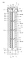
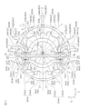
- FIG. 1 is a front view of a signal indicator lamp according to an embodiment of the present invention.
- FIG. 2 is a vertical sectional view of a signal indicator lamp.
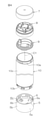
- FIG. 3 is an exploded view of the signal indicator lamp.
- FIG. 4 is an exploded perspective view of a component of a signal indicator lamp.
- 5A is a front view of a substrate which is a component of a signal indicator lamp, and
- FIG. 5B is a rear view of the substrate.
- FIG. 6 is a perspective view of the substrate.
- FIG. 7 is a schematic cross-sectional view of the substrate.
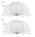
- 8A and 8B are characteristic diagrams showing an example of light distribution characteristics of an LED as a light source.
- 9A and 9B are perspective views and side views of the lens component.
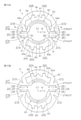
- FIG. 10A and 10B are a plan view and a bottom view of the lens component.
- FIG. 11 is a schematic cross-sectional view of a lens component including a substrate.
- FIG. 12 is an explanatory diagram for explaining the irradiation range of the LED with respect to the incident portion, and is a schematic diagram in which a part of FIG. 11 is enlarged.
- 13A and 13B are explanatory views illustrating an incident region of a light incident portion with respect to one and the other LED of the first pair of light sources.
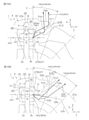
- 14A and 14B are enlarged cross-sectional views of the main part of the lens component, showing the radiation characteristics of the first radiation mechanism and the second radiation mechanism on one side.
- 15A and 15B are enlarged cross-sectional views of the main part of the lens component, showing the radiation characteristics of the third radiation mechanism and the fourth radiation mechanism on one side.
- 16A and 16B are enlarged cross-sectional views of the main part of the lens component, showing the radiation characteristics of the first radiation mechanism and the second radiation mechanism on the other side.
- 17A and 17B are enlarged cross-sectional views of the main part of the lens component, showing the radiation characteristics of the third radiation mechanism and the fourth radiation mechanism on the other side.
- FIG. 18 is a cross-sectional view of a main part of a signal indicator lamp showing a modified example of a lens component.
- FIG. 19 is a cross-sectional view of a main part of a signal indicator lamp showing another modification of the lens component.
- FIG. 20 is a cross-sectional view of a main part of a signal indicator lamp showing still another modification of the lens component.
- FIG. 1 is a front view of the signal indicator lamp 1 according to the first embodiment of the present invention.
- FIG. 2 is a vertical sectional view of the signal indicator lamp 1.
- FIG. 3 is an exploded view of the signal indicator lamp 1.
- FIG. 4 is an exploded perspective view of the main components of the signal indicator lamp 1.
- 5A is a front view of the substrate 3 which is a component of the signal indicator lamp 1
- FIG. 5B is a rear view of the substrate 3.
- FIG. 6 is a perspective view of the substrate 3.
- FIG. 7 is a schematic cross-sectional view of the substrate 3.
- the signal indicator lamp 1 is used at a manufacturing site of a factory or the like, and has an elongated cylindrical shape.
- the posture of the signal indicator lamp 1 at the time of use can be arbitrarily set according to the usage conditions.
- the signal indicator lamp 1 when it is arranged vertically so that the vertical direction of the paper surface in each of FIGS. 1 to 6 coincides with the longitudinal direction of the signal indicator lamp 1 will be described as a reference. ..
- the upper side of the paper surface will be described as the upper side of the signal indicator lamp 1
- the lower side of the paper surface will be described as the lower side of the signal indicator lamp 1.
- the signal indicator 1 includes a substrate 3 on which an LED 2 as a light source is mounted, a lens component 4, a body 5, a plate 6, a head cover 7, an outer top 8, and a waterproof cap 9. ,
- the outer case 10 and the like are included. In the following, each component will be described individually.
- the outer case 10 has a long cylindrical shape and is arranged so as to include the lens component 4.
- the outer case 10 is made of, for example, a translucent material, and allows light from the LED 2 to pass through the lens component 4 to the surroundings.
- the outer case 10 is not formed with a lens cut portion.
- the outer case 10 includes an upper end portion 10a, a lower end portion 10b, and an intermediate portion 10c which is a main body arranged between the upper end portion 10a and the lower end portion 10b. It was
- the head cover 7 is a cylindrical container that opens downward.
- the outer top 8 is a cylindrical member connected to the head cover 7 and the outer case 10.
- the outer top 8 has a support groove 8d (see FIG. 2) that fits and supports the upper end edge (first end edge 3c) of the substrate 3.
- the waterproof cap 9 is contained in the outer top 8.
- the waterproof cap 9 is a ring-shaped packing made of rubber or the like, and seals between the inner peripheral portion of the outer top 8 and the outer peripheral portion of the upper end portion 10a of the outer case 10 (see FIG. 2). ..
- the body 5 has a cylindrical shape that opens upward, and includes a bottom wall 5a and a peripheral side wall 5b.
- the plate 6 is a disk-shaped member received by the inner peripheral step portion 5e (see FIG. 2) of the peripheral side wall 5b of the body 5. As shown in FIGS. 2 to 4, a pair of block-shaped support portions 6b that support the lower end edge of the substrate 3 are attached to the upper surface 6a of the plate 6. Each support portion 6b forms a fitting groove 6c that inserts and fits and holds the corresponding supported projection 3e of the substrate 3.
- the substrate 3 is a substantially rectangular thin plate having a longitudinal direction L in the vertical direction and a lateral direction S in the horizontal direction.
- the direction orthogonal to the longitudinal direction L and the lateral direction S is the thickness direction T of the substrate 3.
- the substrate 3 has a front surface 3a and a back surface 3b forming both side surfaces in the thickness direction T.
- the dimension of the substrate 3 in the longitudinal direction L is slightly smaller than the dimension in the longitudinal direction of the signal indicator lamp 1 (see FIG. 2).
- the substrate 3 has a first edge 3c and a second edge 3d in the longitudinal direction L.
- the first edge 3c corresponds to the upper edge
- the second edge 3d corresponds to the lower edge.
- a pair of supported protrusions 3e projecting downward are provided on the second edge 3d in the longitudinal direction L.
- Each supported projection 3e is supported by the support portion 6b of the plate 6.
- the substrate 3 has a first edge 3f and a second edge 3g in the lateral direction S.
- An LED (light emitting diode) 2 as a light source is mounted on each of the front surface 3a and the back surface 3b at positions close to the first edge 3f and the second edge 3g in the lateral direction S, respectively.
- the LED 2 mounted on the front surface 3a and the LED 2 mounted on the back surface 3b are at the same position in the lateral direction S (see FIG. 7).
- a plurality of LEDs 2 are mounted side by side in two rows along the longitudinal direction L. Specifically, in each row, five LEDs 2 arranged at equal intervals along the longitudinal direction L are arranged in order from the top, one set GA, GB, GC, GD (generally speaking, simply set G). The four sets G are arranged at equal intervals along the longitudinal direction L. That is, on the substrate 3, a plurality of sets of LEDs 2 are mounted in the longitudinal direction L at predetermined intervals. Further, each LED 2 has a small piece shape. Then, in each row of each set G, the LED 2 on the front surface 3a and the LED 2 on the back surface 3b are arranged one by one at the same position in the longitudinal direction L.
- the LED 2 arranged on the front surface 3a and the back surface 3b at a position close to the first edge 3f in the lateral direction S at each position in the longitudinal direction L is the first.
- the LEDs 2 forming the first pair P1 share an optical axis AX with each other and emit light in opposite directions to each other.
- the LEDs 2 arranged on the front surface 3a and the back surface 3b form a second pair P2 at a position close to the second edge 3g in the lateral direction S.
- the LEDs 2 forming the second pair P2 arrange their optical axes AX on the same optical axis line AX1 and emit light in opposite directions.
- Each light source (LED2) is arranged at the light source position Q of the lens component.
- the central position Q0 between the pair of light source positions Q where the light sources (LED2) forming the first pair P1 are arranged is at the central position of the substrate 3 in the thickness direction T (the central position between the front surface 3a and the back surface 3b). Equivalent to.
- the central position Q0 between the pair of light source positions Q where the light sources (LED2) forming the second pair P2 are arranged is the central position in the thickness direction T of the substrate 3 (the central position between the front surface 3a and the back surface 3b).
- the terminal 12 is mounted on the back surface 3b at a position close to the second end edge 3d (lower end edge) in the longitudinal direction L.
- a cable (not shown) for supplying a control signal and electric power is connected to the terminal 12.
- the terminal 12 and each LED 2 are electrically connected to each other. Each LED 2 emits light when a control signal or electric power is supplied from the cable via the terminal 12.
- FIG. 8A is a characteristic diagram showing an example of the light distribution characteristics of the light source (LED2) applicable to the lens component 4.
- the luminous intensity is highest in the direction along the optical axis (direction in which the radiation angle is 0 °), and the luminous intensity decreases monotonically as the distance from the optical axis increases, with respect to the direction along the optical axis (direction in which the radiation angle is 0 °).
- Luminous intensities in orthogonal directions are substantially zero.
- a direction forming a certain angle with respect to a direction along the optical axis (direction in which the radiation angle is 0 °).
- the one having the highest luminous intensity can be used.
- the lens components 4 are provided in the same number (that is, four) as the set G of the LEDs 2 described above, and the form (shape and size) of each lens component 4 is the same.
- These four lens components 4 are connected and used in the vertical direction (longitudinal direction L of the substrate 3). That is, each lens component 4 is used by connecting another lens component 4 having the same shape as itself in the longitudinal direction L, and in the signal indicator 1, a plurality (4) lens components 4 are used. It is installed continuously.
- the lens components 4A, 4B, 4C, and 4D are the set GA of the LED2, respectively.
- the lens components 4A, 4B, 4C, and 4D are the set GA of the LED2, respectively.
- the lens components 4A, 4B, 4C, and 4D are the set GA of the LED2, respectively.
- the lens components 4A, 4B, 4C, and 4D are the set GA of the LED2, respectively.
- the lens components 4A, 4B, 4C, and 4D are the set GA of the LED2, respectively.
- GB, GC, GD corresponds to GB, GC, GD.
- Each lens component 4 has the same form, but may be colored in a different color from each other. Alternatively, while each lens component 4 has the same color, the emission color of the LED 2 that emits light toward each lens component 4 may be different for each lens component 4. Further, in each lens component 4, the five LEDs 2 arranged in the longitudinal direction L may be turned on in sequence from above or below, and then turned off repeatedly.
- FIG. 9A is a perspective view of the lens component 4.
- FIG. 9B is a side view of the lens component 4.
- FIG. 10A is a plan view of the lens component 4.
- FIG. 10B is a bottom view of the lens component 4.
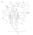
- FIG. 11 is a schematic cross-sectional view of a lens component including a substrate.
- FIG. 12 is an explanatory diagram for explaining the irradiation range of the LED 2 with respect to the incident portion, and is a schematic diagram in which a part of FIG. 11 is enlarged.
- FIG. 13A is an explanatory diagram illustrating an incident region of a light incident portion on one of the LEDs 2 of the first pair P1.
- FIG. 13B is an explanatory diagram illustrating an incident region of a light incident portion with respect to the other LED 2 of the LED 2 of the first pair P1.
- lens component 4 will be described with reference to FIGS. 9 to 13B.
- the lens component 4 has a substantially cylindrical shape.
- the entire lens component 4 is made of a transparent resin (including translucent and colored transparent, the same applies hereinafter), and is molded by injection molding or the like using a mold. Each part (described later) in the lens component 4 is integrated.
- the resin include acrylic resin.
- the lens component 4 is first connected to a top surface 4e, a bottom surface 4f, a light guide radiating unit 20 arranged in a plurality of stages vertically, for example, five stages, and a connecting structure unit 30 for connecting the light guide radiating units 20 to each other.
- the portion 41 and the second connecting portion 42 are mainly included.
- the upper surface 4e of the lens component 4 is the upper surface of the light guide emitting portion 20 at the uppermost stage.
- the lower surface 4f of the lens component 4 is the lower surface of the light guide emitting portion 20 in the lowermost stage.
- Each light guide emitting unit 20 has a central axis C1 and is formed in a short cylindrical shape in the vertical direction.
- a gap 4s at a predetermined interval is provided between the light guide emitting portions 20 adjacent to each other in the vertical direction.
- the light guide radiating portions 20 arranged vertically correspond to the LEDs 2 arranged vertically (longitudinal direction L of the substrate 3) in the set G of the LEDs 2 (see FIGS. 5A and 5B).
- four LEDs 2 (see FIGS. 7 and 11) arranged at the same vertical position (height position) as each light guide radiation unit 20 correspond to each light guide radiation unit 20.
- the light guide radiating portion 20 includes an outer peripheral portion 20a, an inner peripheral portion 20b, four outer axial grooves 21A, 21B, 21C, 21D formed in the outer peripheral portion 20a, and four formed in the inner peripheral portion 20b. It includes inner axial grooves 22A, 22B, 22C, 22D, a first slit portion 23, and a second slit portion 24.
- the outer peripheral portion 20a is formed by a substantially cylindrical surface centered on the central axis C1. Specifically, it includes a portion formed by a cylindrical surface and a portion formed by a curved surface or a plane similar to the cylindrical surface.
- the inner peripheral portion 20b includes a portion formed by a cylindrical surface centered on the central axis C1 and a portion of a concave groove or a ridge extending in the radial direction and extending in the axial direction.
- the first slit portion 23 and the second slit portion 24 are grooves formed in the inner peripheral portion 20b and extending in the axial direction X, and have a groove bottom close to the outer peripheral portion 20a side.
- the first slit portion 23 and the second slit portion 24 are formed so as to face each other in a direction parallel to the radial direction R.
- Each of the first slit portion 23 and the second slit portion 24 includes a holding groove 25 and a pair of light source accommodating recesses 26.
- the holding groove 25 of the first slit portion 23 and the holding groove 25 of the second slit portion 24 are arranged on the groove bottom side of each of the slit portions 23 and 24, and the first end edge 3f and the first edge 3f in the lateral direction S of the substrate 3 are arranged. Holds 3 g of each of the two edge edges.
- the light source accommodating recess 26 of the first slit portion 23 and the second slit portion 24 is arranged adjacent to the central axis C1 side with respect to the holding groove 25 in each of the slit portions 23 and 24.
- Each light source accommodating recess 26 is a recess formed on a pair of inner side surfaces of the corresponding slit portions 23, 24.
- the LED 2 as a corresponding light source is accommodated in the pair of light source accommodating recesses 26 of the slit portions 23 and 24.
- a pair of incident surfaces 27 constituting the light incident portion N are formed by the bottoms of the pair of light source accommodating recesses 26 of the slit portions 23 and 24.
- the pair of incident surfaces 27 one (left side in FIG. 11) is referred to as the incident surface 27A, and the other (right side in FIG. 11) is referred to as the incident surface 27B.
- These incident surfaces 27 are arranged so as to face each other with the corresponding slit portions 23 and 24 interposed therebetween.
- These incident surfaces 27 may be flat surfaces extending in parallel, or may bulge in a substantially arc shape in a direction approaching each other as shown in FIGS. 11 and 12. That is, a convex lens surface that protrudes toward the corresponding LED2 side may be formed on the incident surface 27.
- the light from the LED 2 can be condensed and incident on the incident surface 27 formed by the convex lens surface.
- the connecting structure portion 30 is a cylindrical member in which a first slit portion 31 and a second slit portion 32 extending in the axial direction X are formed.
- the connecting structure portion 30 and the light guide emitting portion 20 share a central axis C1. That is, the connecting structure portion 30 is concentric with the light guide radiation unit 20 and has a smaller diameter than the light guide radiation unit 20.
- the first slit portion 31 of the connecting structure portion 30 communicates with the first slit portion 23 of the light guide radiation portion 20.
- the second slit portion 32 of the connecting structure portion 30 communicates with the second slit portion 24 of the light guide radiation portion 20.
- the connecting structure portion 30 is composed of a first C-shaped member 33 and a second C-shaped member 34 divided by both slit portions 31 and 32.
- the first C-shaped member 33 includes connecting portions 33a and 33b connected to the light guide radiating portion 20 of each stage at both ends in the circumferential direction.
- the second C-shaped member 34 includes connecting portions 34a and 34b connected to each light guide radiating portion 20 at both ends in the circumferential direction.
- the light guide radiating portions 20 in the upper and lower five stages are connected to each other by the action of the connecting portions 33a, 33b; 34a, 34b of both C-shaped members 33, 34.
- the inner side surfaces of the slit portions 31 and 32 of the connecting structure portion 30 face each other with the substrate 3 interposed therebetween, and have a function of restricting the position of the substrate 3.
- the first connecting portion 41 is a pair of fitting protrusions formed so as to protrude from the upper end of the connecting structure portion 30 so as to protrude from the upper surface 4e of the lens component 4.
- Each fitting protrusion as the first connecting portion 41 is an arcuate protrusion concentric with the corresponding C-shaped members 33, 34.
- the second connecting portion 42 is a pair of protrusions formed so as to protrude from the lower end of the connecting structure portion 30 so as to protrude from the lower surface 4f of the lens component 4.
- Each protrusion as the second connecting portion 42 is an arcuate protrusion concentric with the corresponding C-shaped members 33 and 34, and each first connecting portion 41 of the corresponding lens component 4 is fitted to the inner peripheral portion.
- the fitting groove 43 is formed.
- the corresponding lens parts 4 are radially and axially aligned with each other. They are connected so that the relative displacements in the directional and circumferential directions are regulated.
- the light guide emitting unit 20 has a first axis Y and a second axis Z orthogonal to the central axis C1 and orthogonal to each other.
- the LED 2 mounted on the substrate 3 held in the holding groove 25 of the light guide radiation unit 20 has the first axis with respect to the second axis Z.
- the optical axis AX is aligned with the optical axis AX1 parallel to the second axis Z.
- the light guide emitting unit 20 guides the light from the LED 2 and radiates the light radially toward the periphery of the central axis C1 in a direction away from the central axis C1.
- the central position Q0 (the central position in the thickness direction T of the substrate 3) between the light source positions Q of the light sources (LED2) forming the first pair P1 is. It is arranged so as to be offset in a direction parallel to the second axis Z (left side in FIG. 11) with respect to the first axis Y. That is, the substrate 3 is arranged offset with respect to the central axis C1 in the direction of the second axis Z.
- the light guide emitting unit 20 includes a light incident unit N having an incident surface 27 (27A, 27B) and a plurality of radiation mechanisms H1, H2, H3, H4; H1b, H2b, H3b, H4b; H1c, H2c, H3c, H4c.
- Includes H1d, H2d, H3d, H4d (collectively referred to simply as radiation mechanism H).
- the plurality of radiation mechanisms H guide the light incident from the light incident portion and have a plurality of radiation angle ranges HA1, HA2, HA3, HA4; HA1b, HA2b, defined by a plurality of central angles centered on the central axis C1.
- HA3b, HA4b HA1c, HA2c, HA3c, HA4c; HA1d, HAA2d, HA3d, HA4d (collectively, simply referred to as radiation angle range HA).
- the incident surfaces 27A and 27B (27) collect the light from the LED 2 arranged at the light source position Q and incident on the plurality of radiation mechanisms H, respectively.
- the plurality of incident region NAs include a near-side incident region KNA close to the optical axis AX1 and a remote-side incident region ENA located farther from the optical axis AX1 than the near-side incident region KNA.
- a plurality of radiation angle ranges HA are closer to the first axis Y side than the second axis Z side, and the proximity side radiation angle range KHA and the proximity side radiation angle range KHA.
- the boundary between the near-side radiation angle range KHA and the remote-side radiation angle range EHA passes through the central axis C1 and is 45 degrees with respect to the first axis Y and the second axis Z. It is a line that makes up.
- the remote incident region ENA includes a first incident region NA1 and a second incident region NA2 arranged on opposite sides of the optical axis AX1. Further, the proximity side incident region KNA is arranged between the first incident region NA1 and the optical axis AX1 and the third incident region NA3, and the second incident region NA2 and the optical axis AX1. Includes incident region NA4.
- Each of the first incident region NA1 and the second incident region NA2, which are the remote incident region ENA, is set to a wider angle range than each of the third incident region NA3 and the fourth incident region NA4, which are the close incident region KNA. ing.
- the proximity side radiation angle range KHA When viewed in the direction of the central axis C1, the proximity side radiation angle range KHA is on the opposite side of the first axis Y with respect to the first radiation angle range HA1 adjacent to the first axis Y and the first radiation angle range HA1. Includes a second radiation angle range HA2 adjacent to.
- the mechanism that radiates light to the proximity side radiation angle range KHA is the proximity side radiation mechanism KH.
- the proximity side radiation mechanism KH includes a first radiation mechanism H1 that emits light to the first radiation angle range HA1 and a second radiation mechanism H2 that emits light to the second radiation angle range HA2.
- the remote radiation angle range EHA When viewed in the direction of the central axis C1, the remote radiation angle range EHA is the third radiation angle range HA3 and the second radiation angle range HA3 adjacent to the opposite side of the first radiation angle range HA1 with respect to the second radiation angle range HA2. Includes a fourth radiation angle range HA4 adjacent to the third radiation angle range HA3 side with respect to the axis Z.
- the mechanism that radiates light to the remote radiation angle range EHA is the remote radiation mechanism EH.
- the remote radiation mechanism EH includes a third radiation mechanism H3 that emits light to the third radiation angle range HA3 and a fourth radiation mechanism H4 that emits light to the fourth radiation angle range HA4.
- Incident light from the first incident region NA1, the second incident region NA2, the third incident region NA3, and the fourth incident region NA4 is guided via the corresponding radiation mechanism H.
- the incident light from the first incident region NA1 is guided through the first radiation mechanism H1 and radiated to the first radiation angle range HA1.
- the incident light from the second incident region NA2 is guided through the second radiation mechanism H2 and radiated to the second radiation angle range HA2.
- the incident light from the third incident region NA3 is guided through the third radiation mechanism H3 and radiated to the third radiation angle range HA3.
- the incident light from the fourth incident region NA4 is guided through the fourth radiation mechanism H4 and radiated to the fourth radiation angle range HA4.
- the length of the optical path in the light guide radiator 20 until the light incident on the near-side incident region KNA is radiated to the remote-side radiation angle range EHA via the corresponding radiation mechanism H is set to the remote-side incident region ENA.
- the incident light is made longer than the optical path length in the light guide radiation unit 20 until it is radiated to the proximity side radiation angle range KHA via the corresponding radiation mechanism H.
- each radiation mechanism H1 to H4 emits light with the same amount of light.
- the first radiation mechanism H1 as the proximity side radiation mechanism KH will be described with reference to FIG. 14A.
- the first radiation mechanism H1 includes the first reflection surface 51 and the first emission surface 52, and is adjacent to the first axis Y when viewed in the direction of the central axis C1. Light is emitted to the first radiation angle range HA1 as the radiation angle range KHA.
- the outer axial groove 21A formed in the outer peripheral portion 20a of the light guide radiation portion 20 has a substantially triangular cross section.
- the outer axial groove 21A includes, as an inner surface, a first inner surface 211 facing the back side of the incident surface 27A and a second inner surface 212 inclined and opposed to the first inner surface 211.
- the first reflecting surface 51 is an internal reflecting surface along the first inner surface of the outer axial groove 21A.
- the first reflecting surface 51 totally reflects the incident light from the first incident region NA1 as the remote incident region ENA of the incident surface 27A.
- the first exit surface 52 is provided on the outer peripheral portion 20a.
- the first emission surface 52 transmits and emits the reflected light from the first reflection surface 51 to the first radiation angle range HA1.
- the first radiation mechanism H1 has the following advantages over the prior art.
- the light incident on the auxiliary lens portion for radiating to the side substantially orthogonal to the optical axis is the direct irradiation light leaking from the slit portion, which is the farthest and narrowest from the optical axis. It is the light in the irradiation range.
- the first reflecting surface 51 is an internal reflecting surface along the first inner surface 211 facing the back side of the incident surface 27A among the inner surfaces of the outer axial groove 21A of the outer peripheral portion 20a. be.
- the first reflecting surface 51 is preferably a condensing surface (for example, a concave lens surface), and when the first reflecting surface 51 is a condensing surface, it suppresses the diffusion of light and is visually recognized from the first radiation angle range HA1.
- the sex can be improved.
- the first reflecting surface 51 When viewed in the direction of the central axis C1, the first reflecting surface 51 defines a second radiation angle range HA2, which is a radiation angle range adjacent to the opposite side of the first axis Y with respect to the first radiation angle range HA1. It is located within the range of the central angle.
- the degree of freedom in setting the width of the first reflecting surface 51 and the inclination of the first emitting surface 52 with respect to the optical axis AX is set. Is improved. Therefore, light having a wide irradiation range can be guided from the LED 2 as a light source to the first reflecting surface 51 and reflected on the first emitting surface 52 side.
- the amount of light in the first radiation angle range HA1 can be increased to improve visibility.
- the first emission surface 52 includes a refraction surface that refracts and emits the reflected light from the first reflection surface 51 so as to be directed toward the center side of the first radiation angle range HA1. In that case, the visibility of the first radiation angle range HA1 can be improved.
- the second radiation mechanism H2 as the proximity side radiation mechanism KH will be described with reference to FIG. 14B.
- the second radiation mechanism H2 includes the second reflection surface 53 and the second emission surface 54 with respect to the first radiation angle range HA1 when viewed in the direction of the central axis C1.
- Light is emitted to the second radiation angle range HA2 as the proximity side radiation angle range adjacent to the opposite side of the first axis Y.
- the second reflecting surface 53 is an internal reflecting surface along the inner peripheral portion 20b of the light guide emitting portion 20, and totally reflects the incident light from the second incident region NA2 as the remote incident region of the incident surface 27A.
- the second emission surface 54 is provided on the outer peripheral portion 20a of the light guide emitting portion 20, and transmits and emits the reflected light from the second reflecting surface 53 to the second emission angle range HA2.
- the second reflecting surface 53 is preferably a condensing surface (for example, a concave lens surface), and when the second reflecting surface 53 is a condensing surface, it suppresses the diffusion of light and is visually recognized from the second radiation angle range HA2.
- the sex can be improved.
- the second reflecting surface 53 is arranged within the range of the central angle that defines the second radiation angle range HA2.
- the optical path length in the light guide radiation unit 20 can be shortened, and the loss of light in the light guide radiation unit 20 can be reduced. Therefore, the amount of light emitted to the second radiation angle range HA2 can be increased to improve the visibility of the second radiation angle range HA2.
- the second exit surface 54 includes a refracting surface that refracts and emits the reflected light from the second reflecting surface 53 toward the center side of the second radiation angle range HA2. In that case, the visibility from the second radiation angle range HA2 can be improved.
- the second reflecting surface 53 is arranged on the inner surface of the outer axial groove 21A and behind the second inner surface 212 that is inclined and opposed to the first inner surface 211. There is.
- a light guide plate portion 55 connecting the incident surface 27A (light incident portion) of the light guide emitting portion 20 and the outer peripheral portion 20a is formed between the second inner surface 212 and the second reflecting surface 53.
- the light guide plate portion 55 formed between the second inner surface 212 and the second reflecting surface 53 of the outer axial groove 21A of the outer peripheral portion 20a is formed on the outer periphery from the incident surface 27A (light incident portion). It can be used for guiding light to the portion 20a side.
- the light guide plate portion 55 guides the incident light from the incident regions NA2, NA3, and NA4 excluding the first incident region NA1 among the plurality of incident regions NA1 to NA4 of the incident surface 27A (FIG. 14B, FIG. 15A, 15B). That is, the light guide plate portion 55 can be used to guide the incident light from the incident region other than the first incident region NA1.
- the third radiation mechanism H3 as the remote radiation mechanism EH will be described with reference to FIG. 15A.
- the third radiation mechanism H3 includes a first light guide surface 56, a second light guide surface 57, a third reflection surface 58, and a third emission surface 59, and has a central axis C1.
- the third radiation angle range HA3 as the remote side radiation angle range EHA adjacent to the opposite side of the first radiation angle range HA1 with respect to the second radiation angle range HA2.
- the first light guide surface 56 is a light guide surface along the outer peripheral portion 20a of the light guide radiation portion 20, and totally reflects the incident light from the third incident region NA3 as the proximity side incident region KNA of the incident surface 27A.
- the second light guide surface 57 is a light guide surface along the inner peripheral portion 20b of the light guide radiation unit 20, and totally reflects the light reflected from the first light guide surface 56.
- An inner axial groove 22A extending in the axial direction is formed in the inner peripheral portion 20b of the light guide radiating portion 20.
- the inner axial groove 22A has a cross-sectional groove shape, and is partitioned by a first inner surface 221 and a second inner surface 222 facing each other and a groove bottom surface 223.
- the third reflecting surface 58 is an internal reflecting surface along the first inner surface 221 of the inner axial groove 22A formed in the inner peripheral portion 20b, and totally reflects the reflected light from the second light guide surface 57.
- the third emission surface 59 is provided on the outer peripheral portion 20a of the light guide emitting portion 20, and transmits and emits the reflected light from the third reflecting surface 58 to the third emission angle range HA3.
- the light incident from the third incident region NA3 is the first light guide surface 56 along the outer peripheral portion 20a, the second light guide surface 57 along the inner peripheral portion 20b, and the third.
- the light is totally reflected in the order of the reflecting surface 58, and the reflected light from the third reflecting surface 58 is transmitted and emitted from the third emitting surface 59 of the outer peripheral portion 20a to the third emission angle range HA3.
- the third reflection surface 58 is formed by the internal reflection surface along the first inner surface 221 of the inner axial groove 22A formed in the inner peripheral portion 20b of the light guide radiation portion 20, the light guide radiation portion 20 is enlarged.
- the desired third reflecting surface 58 can be easily obtained without doing so.
- first light guide surface 56 is arranged along the second emission surface 54 of the second radiation mechanism H2. Since the second emission surface 54 of the second radiation mechanism H2 and the first light guide surface 56 of the third radiation mechanism H3 are formed in a common portion, miniaturization can be achieved.
- the second light guide surface 57 and the third reflection surface 58 are arranged within the range of the central angle defining the third radiation angle range HA3. Therefore, since the second light guide surface 57 and the third reflection surface 58 are collectively arranged, miniaturization can be achieved. Further, the optical path length in the light guide radiation unit 20 in the third radiation mechanism H3 can be shortened to reduce the loss of light.
- At least one of the first light guide surface 56, the second light guide surface 57, and the third reflection surface 58 is a condensing surface (for example, a concave lens surface).
- the visibility from the radiation angle range HA3 can be improved.
- the fourth radiation mechanism H4 as the remote radiation mechanism EH will be described with reference to FIG. 15B.
- the fourth radiation mechanism H4 has a first light guide surface 56 that functions as a reflection surface, a third reflection surface 58 that functions as a transmission surface, a re-incident surface 60, and a fourth reflection surface 61. And the fourth exit surface 62.
- the fourth radiation mechanism H4 emits light to the fourth radiation angle range HA4 as the remote side radiation angle range EHA adjacent to the third radiation angle range HA3 side with respect to the second axis Z when viewed in the direction of the central axis C1. Radiate.
- the first light guide surface 56 in the fourth radiation mechanism H4 functions as a reflection surface that totally reflects the incident light from the fourth incident region NA4 as the proximity side incident region KNA.
- the third reflecting surface 58 in the fourth radiation mechanism H4 functions as a transmitting surface for transmitting the reflected light from the first light guide surface 56 into the inner axial groove 22A.
- the re-incident surface 60 is a second inner surface 222 of the inner surface of the inner axial groove 22A facing the first inner surface 221, and the transmitted light transmitted through the third reflecting surface 58 is re-incident into the light guide emitting unit 20.
- the fourth reflecting surface 61 is an internal reflecting surface along the inner peripheral portion 20b of the light guide emitting portion 20, and totally reflects the reincident light incident from the reincident surface 60.
- the fourth exit surface 62 is provided on the outer peripheral portion 20a of the light guide emitting portion 20, and transmits and emits the reflected light from the fourth reflecting surface 61 to the fourth radiation angle range HA4.
- the incident light from the fourth incident region NA4 is totally reflected by the first light guide surface 56 along the outer peripheral portion 20a, and the reflected light from the first light guide surface 56 is reflected. , It is transmitted into the inner axial groove 22A through the third reflection surface 58 which functions as a transmission surface.
- the transmitted light transmitted through the third reflecting surface 58 is re-incidented into the light guide emitting portion 20 from the re-incident surface 60 formed by the second inner surface 222 of the inner axial groove 22A.
- the reincident light from the reincident surface 60 is totally reflected by the fourth reflecting surface 61 along the inner peripheral portion 20b.
- the reflected light from the fourth reflecting surface 61 is transmitted and emitted from the fourth emitting surface 62 of the outer peripheral portion 20a to the fourth emission angle range HA4.
- the third reflection surface 58 of the third radiation mechanism H3 functions as a transmission surface. Therefore, the inside of the light guide radiation unit 20 can be effectively used as an optical path for the third radiation mechanism H3 and the fourth radiation mechanism H4 without increasing the size of the light guide radiation unit 20.
- the re-incident surface 60 and the fourth reflecting surface 61 are arranged within the range of the central angle defining the fourth radiation angle range HA4. Since the re-incident surface 60 and the fourth reflecting surface 61 are collectively arranged, miniaturization can be achieved. Further, the optical path length in the light guide radiation unit 20 in the fourth radiation mechanism H4 can be shortened to reduce the loss of light.
- the re-incident surface 60 is a condensing surface (for example, a concave lens surface), and it is possible to suppress the diffusion of light and improve the visibility from the fourth radiation angle range HA4.
- the third reflecting surface 58 functions as a light-collecting reflection surface in the third radiation mechanism H3 and functions as a diffusion transmission surface in the fourth radiation mechanism H4. That is, since the third reflecting surface 58 functions as a light-collecting reflection surface in the third radiation mechanism H3, the third reflection surface 58 functions as a diffusion transmission surface in the fourth radiation mechanism H4. Therefore, when the re-incident surface 60 includes a condensing surface, a greater effect can be obtained in order to suppress the diffusion of light and improve the visibility of the fourth radiation angle range HA4.
- the light guide emitting unit 20 when viewed in the direction of the central axis C1, the light guide emitting unit 20 is on the upper side of the second axis Z (the light source side of the first pair P1) and on the right side of the first axis Y.
- the first radiation mechanism H1b that emits light to the first radiation angle range HA1b
- the second radiation mechanism H2b that emits light to the second radiation angle range HA2b
- the second radiation mechanism H2b in the range of 90 ° (on the incident surface 27B side).
- the third radiation mechanism H3b that emits light to the third radiation angle range HA3b and the fourth radiation mechanism H4d that emits light to the fourth radiation angle range HA4b are included.
- the configurations and functions of the first radiation mechanism H1b, the second radiation mechanism H2b, the third radiation mechanism H3b, and the fourth radiation mechanism H4b are the first radiation mechanism H1, the second radiation mechanism H2, and the third radiation described above, respectively. It is almost the same as the configuration and function of the mechanism H3 and the fourth radiation mechanism H4.
- the first reflection surface 51b and the first emission surface 52b in the first radiation mechanism H1b are the first reflection surface 51 and the first reflection surface 51 in the first radiation mechanism H1 (see FIG. 14A) described above. It corresponds to each of the emission surfaces 52. Further, the outer axial groove 21B corresponds to the outer axial groove 21A (see FIG. 14A).
- the first radiation mechanism H1b the light incident from the first incident region NA1 which is the remote incident region ENA is totally reflected by the first reflecting surface 51b, transmitted and emitted from the first emitting surface 52b, and the radiation angle on the near side is emitted. It is radiated to the first radiation angle range HA1b, which is the range KHA.
- the second reflection surface 53b and the second emission surface 54b in the second radiation mechanism H2b are the second reflection surface 53 and the second emission surface in the second radiation mechanism H2 (see FIG. 14B) described above. Each corresponds to 54.
- the light incident from the second incident region NA2 which is the remote incident region ENA, is totally reflected by the second reflecting surface 53b, and the near radiation angle range KHA passes through the second emitting surface 54b. It is radiated to the second radiation angle range HA2b.
- the first light guide surface 56b, the second light guide surface 57b, the third reflection surface 58b, and the third emission surface 59b in the third radiation mechanism H3b are the above-mentioned third radiation mechanism H3 (FIG. 15A). It corresponds to the first light guide surface 56, the second light guide surface 57, the third reflection surface 58, and the third emission surface 59, respectively. Further, the inner axial groove 22B corresponds to the inner axial groove 22A (FIG. 15A).
- the light incident from the third incident region NA3, which is the proximity side incident region KNA is totally reflected by the first light guide surface 56b, the second light guide surface 57b, and the third reflection surface 58b in that order. Then, it is radiated to the third radiation angle range HA3b, which is the remote radiation angle range EHA, via the third emission surface 59b.
- the first light guide surface 56b, the third reflection surface 58b, the reincident surface 60b, the fourth reflection surface 61b, and the fourth emission surface 62b in the fourth radiation mechanism H4b are the fourth radiation mechanism described above. It corresponds to the first light guide surface 56, the third reflection surface 58, the reincident surface 60, the fourth reflection surface 61, and the fourth emission surface 62 in H4 (see FIG. 15B), respectively.
- the light incident from the fourth incident region NA4 which is the incident region KNA on the near side, is reflected by the first light guide surface 56b that functions as the reflecting surface, and then functions as the transmitting surface.
- the reflection surface 58b is transmitted to the inner axial groove 22B side, then re-incident from the re-incident surface 60 and totally reflected by the fourth reflection surface 61b, and is totally reflected by the fourth emission surface 62b in the remote side emission angle range EHA. It is emitted to a certain fourth radiation angle range HA4b.
- the configuration of the light guide emitting unit 20 in a range of 180 ° below the second axis Z (the light source side of the second pair P2) and The configuration of the light guide emitting unit 20 in the range of 180 ° above the second axis Z (the light source side of the first pair P1) is symmetrical with respect to the second axis Z.
- the first radiation mechanism H1c that emits light to the first radiation angle range HA1c
- the second radiation mechanism H2c that emits light to the second radiation angle range HA2c
- the third radiation angle range HA3c The third radiation mechanism H3c and the fourth radiation mechanism H4c that emits light to the fourth radiation angle range HA4c are the first radiation mechanism H1, the second radiation mechanism H2, the third radiation mechanism H3, and the fourth radiation mechanism H4, respectively.
- the first radiation mechanism H1c that emits light to the first radiation angle range HA1c
- the second radiation mechanism H2c that emits light to the second radiation angle range HA2c
- the third radiation angle range HA3c the fourth radiation mechanism H4c
- the first radiation mechanism H1d that emits light to the first radiation angle range HA1d the second radiation mechanism H2d that emits light to the second radiation angle range HA2d, and the third radiation that emits light to the third radiation angle range HA3d.
- the mechanism H3d and the fourth radiation mechanism H4d that emits light to the fourth radiation angle range HA4d correspond to the first radiation mechanism H1b, the second radiation mechanism H2b, the third radiation mechanism H3b, and the fourth radiation mechanism H4b, respectively. ..
- the lens component 4 of this embodiment has the following effects.
- the light guide for radiating to the proximity side radiation angle range KHA on the side close to the first axis Y has a relatively short light guide distance in the light guide radiation unit 20, and is guided.
- the loss of light during light is relatively small.
- the light guide for radiating to the remote side radiation angle range EHA which is close to the second axis Z side and far from the first axis Y has a relatively long light guide distance in the light guide radiation unit 20.
- the light loss during light guiding is relatively large.
- light with a relatively high luminous intensity incident on the near-side incident region KNA radiates to the side where the optical path length is relatively long and the light loss is relatively large, that is, the remote side emission angle range EHA. It is guided to the optical path on the side to be radiated. Further, light having a relatively low luminous intensity incident on the remote side incident region ENA is emitted to the side where the optical path length is relatively short and the light loss is relatively small, that is, the near side emission angle range KHA. It is guided to the optical path on the side of the light. Therefore, it is possible to radiate a uniform amount of light over the entire area in the circumferential direction, and it is possible to improve visibility.
- the third incident region NA3 and the fourth incident region NA4 as the near-side incident region KNA are arranged on both sides of the optical axis AX1, and the first incident region NA1 and the second incident region are arranged. It is placed between NA2. Therefore, the incident region can be effectively used.
- the incident light from the first incident region NA1 and the second incident region NA2, which are the remote incident region ENA is guided via the corresponding radiation mechanism H, and each has a radiation angle range KHA on the close side. It is radiated to one radiation angle range HA1 and a second radiation angle range HA2.
- the incident light from the third incident region NA3 and the fourth incident region NA4, which are the proximity side incident region KNA is guided via the corresponding radiation mechanism H, and each has a remote side emission angle range EHA. It is radiated to the 3 radiation angle range HA3 and the 4th radiation angle range HA4. This makes it possible to practically correspond each incident region with each radiation angle range.
- a plurality of radiation mechanisms H are configured to emit light with the same amount of light as each other. Therefore, the unevenness of visibility in the circumferential direction of the lens component 4 can be suppressed to be small, and the visibility can be further improved.
- the action and effect related to the lens component 4 described above can be obtained.
- the light source includes a first pair of P1 light sources (LED2) that share the optical axes AX of each other and emit light in opposite directions to each other, so that the light source is wide in the circumferential direction. Visibility can be improved in the range.
- a second pair of P2 light sources (LED2) that share each other's optical axes AX and emit light in opposite directions are included, and the first pair of P1 light sources and the second pair of P2 light sources are centered. They are located on opposite sides of the axis C1 in the direction of the first axis Y. Therefore, each light source corresponds to a radiation angle range of 1/4 of the entire circumference, and the amount of light can be improved to improve visibility.
- a substrate 3 having a central axis C1 in the longitudinal direction L and a first axis Y in the lateral direction S is included, and each pair of P1 and P2.
- the light source is mounted on the front surface 3a and the back surface 3b of the substrate 3, respectively.
- the lens component 4 is formed in a cylindrical shape, and a pair of axial directions that accommodate and hold a pair of edge edges 3f and 3g in the lateral direction S of the substrate 3 in the inner peripheral portion 20b of the light guide radiation portion 20 of the lens component 4, respectively. Holding groove 25 is formed.
- the light sources of each pair P1 and P2 are arranged at the light source positions Q on both sides of the substrate 3 via the substrate 3.
- the pair of edge edges 3f and 3 g in the lateral direction S are held in the axial holding groove 25 of the light guide radiation unit 20.
- the signal indicator lamp 1 can be realized with a practical structure.
- the substrate 3 is arranged offset with respect to the central axis C1 in the direction of the second axis Z. Therefore, the degree of freedom in design can be increased. In addition, a space can be secured on the opposite side of the offset side.
- a plurality of cylindrical lens parts 4 can be connected in the axial direction X, and the connecting portions (first connecting portion 41 and second connecting portion 42) of adjacent lens parts 4 can be connected. , Fitted and connected to each other. Therefore, a required number of lens components 4 can be connected in the axial direction X to realize signal indicator lamps 1 having different lengths.
- FIG. 18 is a cross-sectional view showing a modified example of the lens component 4 of the signal indicator lamp 1.
- the lens component 4 includes a plurality of divided bodies 4V1 and 4V2 that are divided in the circumferential direction and coupled to each other.
- the lens component 4 may be divided along the second axis Z, for example. Since the shape of the divided body of the lens component 4 is simplified as compared with the case where the lens component 4 is not divided, it is easy to manufacture. Further, it is possible to realize the lens component 4 corresponding to various angle ranges by using a small number of basic components.
- FIG. 19 is a cross-sectional view showing still another modification of the lens component 4 of the signal indicator lamp 1.
- the lens component 4 when viewed in the direction of the central axis C1, the lens component 4 has a partial cylindrical shape with the second axis Z as a string.
- the lens component 4 includes a support plate portion 28 extending along the strings, and the support plate portion 28 connects the light guide radiation portion 20 and the connecting structure portion 30, both of which form a partially cylindrical shape.
- the support plate portion 28 includes a holding groove 28a that holds the second edge 3g of the substrate 3.
- radiation can be emitted from the light source (LED2) of the first pair P1 on both sides of the first axis Y with 90 ° on each side, for a total emission angle range of 180 °.
- LED2 light source
- FIG. 20 is a cross-sectional view showing still another modification of the lens component 4 of the signal indicator lamp 1.
- the lens component 4 when viewed in the direction of the central axis C1, the lens component 4 forms a partial cylinder having the first axis as a string.
- the lens component 4 includes a support plate portion 29 extending along the chord, and the support plate portion 29 connects the portions facing in the direction of the first axis Y in the light guide radiation portion 20.
- the light source includes a pair of light sources (LED2) that are located on opposite sides of the central axis C1 in the direction of the first axis Y and emit light on the same side in a direction parallel to the second axis Z. In this case, it is possible to radiate from a pair of light sources (LED2) that emit light on the same side to a radiation angle range of 180 ° in total, 90 ° on each side on both sides of the second axis Z.
- the present invention is not limited to the above embodiment, and for example, the central position of the substrate 3 in the thickness direction T may be arranged on the central axis C1 when viewed in the direction of the central axis C1. That is, the substrate 3 does not have to be arranged at an offset. In this case, the symmetry of the lens component is increased, so that the structure can be simplified.
- the present invention may be modified in various ways within the scope of the claims.
Landscapes
- Engineering & Computer Science (AREA)
- General Engineering & Computer Science (AREA)
- Physics & Mathematics (AREA)
- Spectroscopy & Molecular Physics (AREA)
- Microelectronics & Electronic Packaging (AREA)
- Optics & Photonics (AREA)
- Non-Portable Lighting Devices Or Systems Thereof (AREA)
- Planar Illumination Modules (AREA)
- Lenses (AREA)
Abstract
Description
2 LED(光源)
3 基板
3a 表面
3b 裏面
3f 第1端縁
3g 第2端縁
4;4A~4D レンズ部品
4V1;4V2 分割体
20 導光放射部
20a 外周部
20b 内周部
21A~21D 外側軸方向溝
22A~22D 内側軸方向溝
25 保持溝
26 光源収容凹部
27;27A;27B 入射面
30 連結構造部
41 第1連結部
42 第2連結部
43 嵌合溝
51;51b 第1反射面
52;52b 第1出射面
53;53b 第2反射面
54;54b 第2出射面
55 導光板部
56;56b 第1導光面
57;57b 第2導光面
58;58b 第3反射面
59;59b 第3出射面
60;60b 再入射面
61;61b 第4反射面
62;62b 第4出射面
211 第1内面
212 第2内面
221 第1内面
222 第2内面
AX 光軸
AX1 光軸線
C1 中心軸線
EH 遠隔側放射機構
EHA 遠隔側放射角範囲
ENA 遠隔側入射領域
H1;H1b~H1d 第1放射機構
H2;H2b~H2d 第2放射機構
H3;H3b~H3d 第3放射機構
H4;H4b~H4d 第4放射機構
HA1;HA1b~HA1d 第1放射角範囲
HA2;HA2b~HA2d 第2放射角範囲
HA3;HA3b~HA3d 第3放射角範囲
HA4;HA4b~HA4d 第4放射角範囲
KH 近接側放射機構
KHA 近接側放射角範囲
KNA 近接側入射領域
L 長手方向
N 光入射部
NA 入射領域
NA1 第1入射領域
NA2 第2入射領域
NA3 第3入射領域
NA4 第4入射領域
P1 第1の対
P2 第2の対
Q 光源位置
Q0 中央位置
S 短手方向
T 厚さ方向
X 軸方向
Y 第1軸線
Z 第2軸線
Claims (17)
- 光軸から離れるに従って光度が減少する配向特性を有する光源が発生する光を周囲に放射するためのレンズ部品であって、
中心軸線を有する円筒状又は部分円筒状をなし、外周部と内周部とを有し、前記中心軸線に対して直交し且つ互いに直交する第1軸線及び第2軸線のうち前記第2軸線に対して前記第1軸線の方向に離隔した所定の光源位置において前記第2軸線に平行な光軸線に光軸を整合させて配置される光源からの光を導光して、前記中心軸線の周囲に向けて前記中心軸線から離れる放射状に光を放射する導光放射部を備え、
前記導光放射部が、前記光源位置に配置された光源からの光を入射する入射面を有する光入射部と、前記光入射部から入射された光を導いて前記中心軸線を中心とする複数の中心角によってそれぞれ規定される複数の放射角範囲にそれぞれ放射する複数の放射機構と、を含み、
前記入射面が、前記光源位置に配置された光源からの光を集光して前記複数の放射機構にそれぞれ入射する複数の入射領域を含み、前記複数の入射領域は、前記光軸線に近接する近接側入射領域と、前記近接側領域よりも前記光軸線から離れて配置される遠隔側入射領域と、を含み、
前記中心軸線の方向に見たときに、前記複数の放射角範囲が、前記第2軸線側よりも前記第1軸線側に近接する近接側放射角範囲と、前記近接側放射角範囲よりも前記第1軸線側から遠く且つ前記第2軸線側に近い遠隔側放射角範囲と、を含み、
前記放射機構が、前記近接側放射範囲に光を放射する近接側放射機構と、前記遠隔側放射角範囲に光を放射する遠隔側放射機構と、を含み、
前記近接側入射領域に入射される光が、対応する前記遠隔側放射機構を介して前記遠隔側放射角範囲に放射され、
前記遠隔側入射領域に入射される光が、対応する前記近接側放射機構を介して前記近接側放射角範囲に放射される、レンズ部品。 - 前記近接側入射領域に入射される光が対応する前記遠隔側放射機構を介して前記遠隔側放射角範囲に放射されるまでの前記導光放射部内の光路長が、前記遠隔側入射領域に入射される光が対応する前記近接側放射機構を介して前記近接側放射角範囲に放射されるまでの前記導光放射部内の光路長よりも長い、請求項1に記載のレンズ部品。
- 前記遠隔側入射領域が、前記光軸線に対して互いに反対側に配置される第1入射領域と第2入射領域とを含み、前記近接側入射領域が、前記第1入射領域と前記光軸線との間に配置される第3入射領域と、前記第2入射領域と前記光軸線との間に配置される第4入射領域と、を含み、
前記中心軸線の方向に見たときに、前記近接側放射角範囲が、前記第1軸線に隣接する第1放射角範囲と、前記第1放射角範囲に対して前記第1軸線の反対側に隣接する第2放射角範囲と、を含み、
前記中心軸線の方向に見たときに、前記遠隔側放射角範囲が、前記第2放射角範囲に対して前記第1放射角範囲の反対側に隣接する第3放射角範囲と、前記第2軸線に対して前記第3放射角範囲側に隣接する第4放射角範囲と、を含み、前記第1入射領域、前記第2入射領域、前記第3入射領域および前記第4入射領域からの入射光が、対応する放射機構を介して導光されて、それぞれ、前記第1放射角範囲、前記第2放射角範囲、前記第3放射角範囲及び前記第4放射角範囲に放射される、請求項1又は2に記載のレンズ部品。 - 前記近接側放射機構が、前記中心軸線の方向に見たときに前記第1軸線に隣接する前記近接側放射角範囲としての第1放射角範囲に光を放射する第1放射機構を含み、
前記第1放射機構が、前記外周部に形成された外側軸方向溝の内面のうち前記入射面の裏側に対向する第1内面に沿う内部反射面であって前記入射面の前記遠隔側入射領域としての第1入射領域からの入射光を全反射する第1反射面と、前記外周部に設けられ前記第1反射面からの反射光を前記第1放射角範囲に透過出射させる第1出射面と、を含む、1~3の何れか一項に記載のレンズ部品。 - 前記中心軸線の方向に見たときに、前記第1反射面が、前記第1放射角範囲に対して前記第1軸線の反対側に隣接する前記第2放射角範囲を規定する中心角の範囲内に配置されている、請求項4に記載のレンズ部品。
- 前記第1反射面が、集光面を含み、前記第1出射面が、当前記第1反射面からの反射光を前記第1放射角範囲の中央側に促すように屈折出射させる屈折面を含む、請求項4又は5に記載のレンズ部品。
- 前記近接側放射機構が、前記中心軸線の方向に見たときに前記第1放射角範囲に対して前記第1軸線の反対側に隣接する前記近接側放射角範囲としての第2放射角範囲に光を放射する第2放射機構を含み、
前記第2放射機構が、前記内周部に沿う内部反射面であって前記入射面の前記遠隔側入射領域としての第2入射領域からの入射光を全反射する第2反射面と、前記外周部に設けられ前記第2反射面からの反射光を前記第2放射角範囲に透過出射させる第2出射面と、を含む、請求項4~6の何れか一項に記載のレンズ部品。 - 前記第2出射面が、前記第2反射面からの反射光を前記第2放射角範囲の中央側へ促すように屈折出射させる屈折面を含む、請求項7に記載のレンズ部品。
- 前記遠隔側放射機構が、前記中心軸線の方向に見たときに前記第2放射角範囲に対して前記第1放射角範囲の反対側に隣接する前記遠隔側放射角範囲としての第3放射角範囲に光を放射する第3放射機構を含み、
前記第3放射機構が、前記外周部に沿う導光面であって前記入射面の前記近接側入射領域としての第3入射領域からの入射光を全反射させる第1導光面と、前記内周部に沿う導光面であって前記第1導光面からの反射光を全反射させる第2導光面と、前記内周部に形成された内側軸方向溝の第1内面に沿う内部反射面であって前記第2導光面からの反射光を全反射させる第3反射面と、前記外周部に設けられ前記第3反射面からの反射光を前記第3放射角範囲に透過出射させる第3出射面と、を含む、請求項7または請求項8に記載のレンズ部品。 - 前記第1導光面が、前記第2放射機構の前記第2出射面に沿って配置され、前記第2導光面及び前記第3反射面が、前記第3放射角範囲を規定する中心角の範囲内に配置されている、請求項9に記載のレンズ部品。
- 前記遠隔側放射機構が、前記中心軸線の方向に見たときに前記第2軸線に対して前記第3放射角範囲側に隣接する前記遠隔側放射角範囲としての第4放射角範囲に光を放射する第4放射機構を含み、
前記第4放射機構が、前記入射面の前記近接側入射領域としての第4入射領域からの入射光を全反射させる反射面として機能する前記第1導光面と、前記第1導光面からの反射光を前記内側軸方向溝内へ透過させる透過面として機能する前記第3反射面と、前記内側軸方向溝の内面のうち前記第1内面に対向する第2内面であって前記第3反射面を透過した透過光を再入射させる再入射面と、前記導光放射部の内周部に沿う内部反射面であって前記再入射面から入射した再入射光を全反射する第4反射面と、前記外周部に設けられ前記第4反射面からの反射光を前記第4放射角範囲に透過出射させる第4出射面と、を含む、請求項9又は10に記載のレンズ部品。 - 前記再入射面及び前記第4反射面が、前記第4放射角範囲を規定する中心角の範囲内に配置されている、請求項11に記載のレンズ部品。
- 前記第3反射面が、前記第3放射機構における集光反射面として機能し、前記第4放射機構における拡散透過面として機能する、請求項11又は12に記載のレンズ部品。
- 請求項1~13の何れか一項に記載のレンズ部品と、
前記レンズ部品の光源位置に配置される光源と、を含む信号表示灯。 - 前記光源が、互いの光軸を共有し、互いに正反対の方向に発光する第1の対の光源及び/又は第2の対の光源を含み、
前記第1の対の光源及び/又は前記第2の対の光源が、前記中心軸線に対して互いに前記第1軸線の方向の反対側に位置する、請求項14に記載の信号表示灯。 - 前記中心軸線の方向に見たときに、前記レンズ部品が、前記第2軸線を弦とする部分円筒状をなす、請求項15に記載の信号表示灯。
- 前記中心軸線の方向に見たときに、前記レンズ部品が、前記第1軸線を弦とする部分円筒状をなし、
前記光源が、前記中心軸線に対して互いに前記第1軸線の方向の反対側に位置し、前記第2軸に平行な方向で同側に発光する一対の光源を含む、請求項14に記載の信号表示灯。
Priority Applications (6)
| Application Number | Priority Date | Filing Date | Title |
|---|---|---|---|
| KR1020237008499A KR102822661B1 (ko) | 2020-09-16 | 2020-09-16 | 렌즈 부품 및 신호 표시등 |
| CN202080063149.8A CN114521221B (zh) | 2020-09-16 | 2020-09-16 | 透镜部件以及信号显示灯 |
| US17/783,349 US11781734B2 (en) | 2020-09-16 | 2020-09-16 | Lens component and signal display lamp |
| JP2021512953A JP7316533B2 (ja) | 2020-09-16 | 2020-09-16 | レンズ部品及び信号表示灯 |
| EP20954078.0A EP4056891B1 (en) | 2020-09-16 | 2020-09-16 | Lens component and signal display lamp |
| PCT/JP2020/035077 WO2022059092A1 (ja) | 2020-09-16 | 2020-09-16 | レンズ部品及び信号表示灯 |
Applications Claiming Priority (1)
| Application Number | Priority Date | Filing Date | Title |
|---|---|---|---|
| PCT/JP2020/035077 WO2022059092A1 (ja) | 2020-09-16 | 2020-09-16 | レンズ部品及び信号表示灯 |
Publications (1)
| Publication Number | Publication Date |
|---|---|
| WO2022059092A1 true WO2022059092A1 (ja) | 2022-03-24 |
Family
ID=80776556
Family Applications (1)
| Application Number | Title | Priority Date | Filing Date |
|---|---|---|---|
| PCT/JP2020/035077 Ceased WO2022059092A1 (ja) | 2020-09-16 | 2020-09-16 | レンズ部品及び信号表示灯 |
Country Status (6)
| Country | Link |
|---|---|
| US (1) | US11781734B2 (ja) |
| EP (1) | EP4056891B1 (ja) |
| JP (1) | JP7316533B2 (ja) |
| KR (1) | KR102822661B1 (ja) |
| CN (1) | CN114521221B (ja) |
| WO (1) | WO2022059092A1 (ja) |
Families Citing this family (2)
| Publication number | Priority date | Publication date | Assignee | Title |
|---|---|---|---|---|
| US11796138B2 (en) | 2020-11-30 | 2023-10-24 | Patlite Corporation | Indicator light |
| DE102023135286A1 (de) | 2023-12-15 | 2025-06-18 | Werma Holding Gmbh + Co. Kg | Signalgeber-Segment mit Innenfläche zur homogenen Ausleuchtung |
Citations (3)
| Publication number | Priority date | Publication date | Assignee | Title |
|---|---|---|---|---|
| JP2005251689A (ja) * | 2004-03-08 | 2005-09-15 | Patoraito:Kk | 光源装置 |
| JP5954600B2 (ja) | 2013-10-02 | 2016-07-20 | 株式会社パトライト | 信号表示灯 |
| WO2017022143A1 (ja) * | 2015-08-05 | 2017-02-09 | 株式会社パトライト | レンズ部品および発光装置 |
Family Cites Families (8)
| Publication number | Priority date | Publication date | Assignee | Title |
|---|---|---|---|---|
| JP2010049867A (ja) | 2008-08-20 | 2010-03-04 | Sharp Corp | 光源モジュールおよびそれを備えた照明装置 |
| EP2187113A1 (en) * | 2008-11-18 | 2010-05-19 | Toshiba Lighting & Technology Corporation | Lighting device including translucent cover for diffusing light from light source |
| US20100315811A1 (en) * | 2009-06-10 | 2010-12-16 | Shih-Chou Chen | Curved light guiding illuminator |
| WO2013024836A1 (ja) * | 2011-08-12 | 2013-02-21 | シチズン電子株式会社 | レンズ部材及びこのレンズ部材を使用した発光装置 |
| JP2016157640A (ja) | 2015-02-25 | 2016-09-01 | 三菱化学株式会社 | 照明装置及び光学レンズ |
| KR102038945B1 (ko) * | 2015-12-28 | 2019-10-31 | 가부시키가이샤 파토라이토 | 신호표시등용 적층 유닛 및 신호표시등 |
| JP2018014279A (ja) | 2016-07-22 | 2018-01-25 | スタンレー電気株式会社 | 光学レンズ |
| JP6827301B2 (ja) | 2016-11-16 | 2021-02-10 | 三菱電機株式会社 | 光学レンズ、光源装置および照明装置 |
-
2020
- 2020-09-16 KR KR1020237008499A patent/KR102822661B1/ko active Active
- 2020-09-16 US US17/783,349 patent/US11781734B2/en active Active
- 2020-09-16 EP EP20954078.0A patent/EP4056891B1/en active Active
- 2020-09-16 JP JP2021512953A patent/JP7316533B2/ja active Active
- 2020-09-16 CN CN202080063149.8A patent/CN114521221B/zh active Active
- 2020-09-16 WO PCT/JP2020/035077 patent/WO2022059092A1/ja not_active Ceased
Patent Citations (3)
| Publication number | Priority date | Publication date | Assignee | Title |
|---|---|---|---|---|
| JP2005251689A (ja) * | 2004-03-08 | 2005-09-15 | Patoraito:Kk | 光源装置 |
| JP5954600B2 (ja) | 2013-10-02 | 2016-07-20 | 株式会社パトライト | 信号表示灯 |
| WO2017022143A1 (ja) * | 2015-08-05 | 2017-02-09 | 株式会社パトライト | レンズ部品および発光装置 |
Also Published As
| Publication number | Publication date |
|---|---|
| EP4056891A1 (en) | 2022-09-14 |
| JPWO2022059092A1 (ja) | 2022-03-24 |
| KR20230068396A (ko) | 2023-05-17 |
| EP4056891B1 (en) | 2024-04-17 |
| US11781734B2 (en) | 2023-10-10 |
| US20230020496A1 (en) | 2023-01-19 |
| KR102822661B1 (ko) | 2025-06-19 |
| CN114521221B (zh) | 2025-09-09 |
| EP4056891A4 (en) | 2023-08-09 |
| CN114521221A (zh) | 2022-05-20 |
| JP7316533B2 (ja) | 2023-07-28 |
Similar Documents
| Publication | Publication Date | Title |
|---|---|---|
| US7967477B2 (en) | Compact optical system and lenses for producing uniform collimated light | |
| EP2276076B1 (en) | Light emitting unit with lens | |
| US9157602B2 (en) | Optical element for a light source and lighting system using same | |
| EP3290980B1 (en) | Optical lens assembly and illumination device comprising the same | |
| US9709242B2 (en) | Shell integrator | |
| US10775554B2 (en) | Illumination device having light pipe with concentric annular portions | |
| WO2013111534A1 (ja) | 光束制御部材および発光装置 | |
| JP2011192494A (ja) | 照明装置及びフレネルレンズ | |
| JP5245545B2 (ja) | 光源装置および照明器具 | |
| EP2279374B1 (en) | Optical element for asymmetric light distribution | |
| JP2013513198A (ja) | 照明モジュール | |
| WO2022059092A1 (ja) | レンズ部品及び信号表示灯 | |
| EP3094920B1 (en) | Shell integrator | |
| JP2012185955A (ja) | 照明装置 | |
| JP5784366B2 (ja) | 照明装置 | |
| US20190146136A1 (en) | Lighting arrangement with light guide | |
| JP5307717B2 (ja) | 自発光型の発光装置 | |
| JP2013168269A (ja) | 車両用灯具 | |
| KR101837431B1 (ko) | 광품질 개선구조를 갖는 엘이디 조명기구 | |
| US9052418B2 (en) | Light source module | |
| JP2008288413A (ja) | 発光モジュール、発光モジュールアレイ、バックライトユニット、および液晶表示装置 | |
| KR20240102652A (ko) | 램프 | |
| TWI499806B (zh) | 具有側向導光柱的透鏡及由數個該透鏡所構成的側向發光模組 | |
| KR20230101578A (ko) | 엘이디 모듈 | |
| JP2012119251A (ja) | 灯具 |
Legal Events
| Date | Code | Title | Description |
|---|---|---|---|
| ENP | Entry into the national phase |
Ref document number: 2021512953 Country of ref document: JP Kind code of ref document: A |
|
| 121 | Ep: the epo has been informed by wipo that ep was designated in this application |
Ref document number: 20954078 Country of ref document: EP Kind code of ref document: A1 |
|
| ENP | Entry into the national phase |
Ref document number: 2020954078 Country of ref document: EP Effective date: 20220609 |
|
| NENP | Non-entry into the national phase |
Ref country code: DE |
|
| WWG | Wipo information: grant in national office |
Ref document number: 202080063149.8 Country of ref document: CN |