WO2022059483A1 - 無線通信装置および方法 - Google Patents
無線通信装置および方法 Download PDFInfo
- Publication number
- WO2022059483A1 WO2022059483A1 PCT/JP2021/032046 JP2021032046W WO2022059483A1 WO 2022059483 A1 WO2022059483 A1 WO 2022059483A1 JP 2021032046 W JP2021032046 W JP 2021032046W WO 2022059483 A1 WO2022059483 A1 WO 2022059483A1
- Authority
- WO
- WIPO (PCT)
- Prior art keywords
- wireless communication
- transmission
- communication device
- control signal
- information
- Prior art date
- Legal status (The legal status is an assumption and is not a legal conclusion. Google has not performed a legal analysis and makes no representation as to the accuracy of the status listed.)
- Ceased
Links
Images














Classifications
-
- H—ELECTRICITY
- H04—ELECTRIC COMMUNICATION TECHNIQUE
- H04W—WIRELESS COMMUNICATION NETWORKS
- H04W72/00—Local resource management
- H04W72/12—Wireless traffic scheduling
- H04W72/1263—Mapping of traffic onto schedule, e.g. scheduled allocation or multiplexing of flows
- H04W72/1268—Mapping of traffic onto schedule, e.g. scheduled allocation or multiplexing of flows of uplink data flows
-
- H—ELECTRICITY
- H04—ELECTRIC COMMUNICATION TECHNIQUE
- H04L—TRANSMISSION OF DIGITAL INFORMATION, e.g. TELEGRAPHIC COMMUNICATION
- H04L5/00—Arrangements affording multiple use of the transmission path
- H04L5/003—Arrangements for allocating sub-channels of the transmission path
- H04L5/0032—Distributed allocation, i.e. involving a plurality of allocating devices, each making partial allocation
- H04L5/0035—Resource allocation in a cooperative multipoint environment
-
- H—ELECTRICITY
- H04—ELECTRIC COMMUNICATION TECHNIQUE
- H04L—TRANSMISSION OF DIGITAL INFORMATION, e.g. TELEGRAPHIC COMMUNICATION
- H04L5/00—Arrangements affording multiple use of the transmission path
- H04L5/003—Arrangements for allocating sub-channels of the transmission path
- H04L5/0053—Allocation of signalling, i.e. of overhead other than pilot signals
-
- H—ELECTRICITY
- H04—ELECTRIC COMMUNICATION TECHNIQUE
- H04L—TRANSMISSION OF DIGITAL INFORMATION, e.g. TELEGRAPHIC COMMUNICATION
- H04L5/00—Arrangements affording multiple use of the transmission path
- H04L5/0091—Signalling for the administration of the divided path, e.g. signalling of configuration information
-
- H—ELECTRICITY
- H04—ELECTRIC COMMUNICATION TECHNIQUE
- H04W—WIRELESS COMMUNICATION NETWORKS
- H04W72/00—Local resource management
- H04W72/20—Control channels or signalling for resource management
- H04W72/23—Control channels or signalling for resource management in the downlink direction of a wireless link, i.e. towards a terminal
-
- H—ELECTRICITY
- H04—ELECTRIC COMMUNICATION TECHNIQUE
- H04W—WIRELESS COMMUNICATION NETWORKS
- H04W72/00—Local resource management
- H04W72/20—Control channels or signalling for resource management
- H04W72/23—Control channels or signalling for resource management in the downlink direction of a wireless link, i.e. towards a terminal
- H04W72/232—Control channels or signalling for resource management in the downlink direction of a wireless link, i.e. towards a terminal the control data signalling from the physical layer, e.g. DCI signalling
-
- H—ELECTRICITY
- H04—ELECTRIC COMMUNICATION TECHNIQUE
- H04W—WIRELESS COMMUNICATION NETWORKS
- H04W74/00—Wireless channel access
- H04W74/002—Transmission of channel access control information
-
- H—ELECTRICITY
- H04—ELECTRIC COMMUNICATION TECHNIQUE
- H04B—TRANSMISSION
- H04B7/00—Radio transmission systems, i.e. using radiation field
- H04B7/02—Diversity systems; Multi-antenna system, i.e. transmission or reception using multiple antennas
- H04B7/022—Site diversity; Macro-diversity
- H04B7/024—Co-operative use of antennas of several sites, e.g. in co-ordinated multipoint or co-operative multiple-input multiple-output [MIMO] systems
-
- H—ELECTRICITY
- H04—ELECTRIC COMMUNICATION TECHNIQUE
- H04W—WIRELESS COMMUNICATION NETWORKS
- H04W84/00—Network topologies
- H04W84/02—Hierarchically pre-organised networks, e.g. paging networks, cellular networks, WLAN [Wireless Local Area Network] or WLL [Wireless Local Loop]
- H04W84/10—Small scale networks; Flat hierarchical networks
- H04W84/12—WLAN [Wireless Local Area Networks]
Definitions
- the present technology relates to wireless communication devices and methods, and particularly to wireless communication devices and methods that enable optimum data transmission depending on the situation.
- C-SR Coordinated Spatial Reuse
- BSS Basic Set Service
- Non-Patent Document 1 discloses a technique for carrying out C-SR at the time of UL transmission by using the uplink (UpLink, hereinafter UL) OFDMA (Orthogonal Frequency Division Multiple Access) of IEEE802.11ax. ..
- Uplink transmission means transmission from a station (hereinafter referred to as STA), which is a terminal under the AP, to the AP.
- STA station
- DownLink downlink
- Sharing AP transmits information to inform other APs that can cooperate (hereinafter, Shared AP) that C-SR will be performed.
- shared AP transmits Trigger Frame, which is one of the DL control frames required for UL C-SR, and induce UL transmission from STA.
- Non-Patent Document 1 enables STAs in a plurality of BSSs to perform data transmission using the same resource at the same time, and a significant improvement in wireless capacity can be expected.
- Non-Patent Document 1 does not even mention a method of transmitting a DL control frame.
- the DL control frame is a transmission method by NonDuplicate in which different data is transmitted at the same time and using the same resource as much as possible. It is better to be able to transmit using.
- NonDuplicate there may be a case where the signals interfere with each other depending on the reception position and the frame cannot be correctly decoded by low SINR (Signal to Interference and Noise Ratio). It is desirable to use the transmission method and other transmission methods properly.
- This technology was made in view of such a situation, and makes it possible to perform optimum data transmission according to the situation.
- the wireless communication device of one aspect of the present technology is a wireless communication unit that performs uplink transmission, which is transmission from a wireless communication terminal, in cooperation with other wireless communication devices, and a control signal required for the uplink transmission. It includes a transmission method information indicating a transmission method of a downlink control signal, or a communication control unit that acquires information necessary for determining the transmission method from the other wireless communication device.
- uplink transmission which is transmission from a wireless communication terminal, is performed in cooperation with other wireless communication devices. Further, transmission method information indicating a transmission method of the downlink control signal, which is a control signal required for the uplink transmission, or information necessary for determining the transmission method is acquired from the other wireless communication device.
- FIG. 1 is a diagram showing a configuration example of a wireless communication system according to an embodiment of the present technology.
- the solid line arrow indicates that the devices are connected to each other, and the broken line arrow indicates that power is exchanged between the devices.
- AP Access Point
- STA Selection
- the wireless communication system of FIG. 1 is configured by connecting AP1 and AP2 by wire communication or wireless communication.
- the wireless communication device 11-1 and the wireless communication device 11-2 are devices that operate as AP1 and AP2, respectively.
- the wireless communication system is configured by connecting STA1 and STA2 to AP1 by wireless communication and connecting STA3 and STA4 to AP2 by wireless communication.
- the wireless communication terminals 12-1 to 12-4 are devices that operate as STA1 to STA4, respectively.
- STA1 and STA2 connected to AP1 by wireless communication belong to the same BSS (synonymous with cell) as AP1 and are called STAs under AP1.
- STA3 and STA4 connected to AP2 by wireless communication belong to the same BSS and are called STAs under AP2.
- STA2 and STA3 are also close to the AP other than the connection destination, they can receive signals transmitted from the AP other than the connection destination with stronger reception power than STA1 and STA4, which are far from the AP other than the connection destination. is assumed.
- the target system configuration is not limited to the example of FIG. 1, and if there are a plurality of APs for which connection has been established and STA is connected to each AP as a peripheral terminal, the target system configuration is not limited to that of FIG. It may have any configuration.
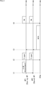
- FIG. 2 is a diagram showing a basic sequence of C-SR at the time of UL transmission, which is a technique disclosed in Non-Patent Document 1.
- the process shown in FIG. 2 is a process performed by AP1, AP2, and STAs.
- STAs represent at least one STA out of STA1 to STA4.
- AP1 is a Sharing AP that has acquired a transmission opportunity
- AP2 is a Shared AP that is permitted to transmit from AP1. That is, AP2 is an AP that can share a transmission opportunity from AP1.
- AP1 sends a C-SR Announcement Frame to AP2.
- the C-SR Announcement Frame contains an interference power value (referred to as an allowable interference power value) that allows AP1 to ensure sufficient communication quality in its own UL transmission, and AP1 scheduling information.
- Scheduling information is information that describes which resource is allocated to which STA under the control.
- AP2 determines UL scheduling consisting of STA that induces UL transmission (transmits Trigger Frame), its resources, transmission power, MCS (Modulation and Coding Scheme), etc., based on the received C-SR Announcement Frame. do.
- These UL scheduling are determined in the order of priority that (1) the interference power value given to AP1 is less than or equal to the allowable interference power value, and (2) the data can be acquired by UL transmission from STA without any problem.
- AP1 / AP2 each transmit a Trigger Frame that induces UL transmission to the subordinate STA.
- the Trigger Frame contains a combination of STA and resource information that induces UL transmission, as described in IEEE802.11ax / D6.0.
- each STA performs UL transmission of DATA to the corresponding AP based on the Trigger Frame.
- AP1 / AP2 sends a BlockAckFrame (hereinafter, BA) that conveys the reception status to the subordinate STA.
- BA may be a Multi-STA Block Ack that stores response signals to a plurality of STAs in a Frame, or may be transmitted to a plurality of STAs using a DL OFDMA signal.
- Non-Patent Document 1 does not mention a method for transmitting DL control signals such as Trigger Frame and BA transmitted from AP1 and AP2.
- DL control signals such as Trigger Frame and BA transmitted from AP1 and AP2.
- the following four transmission methods can be mentioned as transmission methods for DL control signals such as Trigger Frame and BA.
- FIG. 3 is a diagram showing a transmission method of a DL control signal.
- Trigger Frame cannot perform time-division transmission, so that there are substantially four transmission methods. Is a candidate for the transmission method of the DL control signal.
- a of FIG. 3 a configuration example of a channel and a frame used when the transmission method of the DL control signal is Duplicate Frame Tx is shown.
- Duplicate Frame Tx is a transmission method in which AP1 / AP2 generate exactly the same frame and transmit at the same time.
- a of FIG. 3 an example is shown in which AP1 / AP2 simultaneously transmit the same frame to STA1 to STA4 using a plurality of channels of CH1 and CH2.
- the DL control signal can be transmitted to the STA without interference even if the same resources (channel and time information, etc.) are used.
- Duplicate Frame Tx is easy to transmit over a wide band, it must have the same information between APs. Therefore, the use of DuplicateFrameTx creates an overhead for exchanging information.
- B of FIG. 3 a configuration example of a channel and a frame used when the transmission method of the DL control signal is Channel Switching is shown.
- Channel Switching is one of the frequency division multiplexing methods, in which either AP1 / AP2 temporarily moves the Primary Channel (PCH) and transmits the DL control signal in a frequency-divisioned state.
- PCH Primary Channel
- the frame is transmitted to STA1 and STA2 using CH1 in which AP1 is PCH, and AP2 moves the PCH to CH2 and transmits the frame to STA3 and STA4 using CH2.
- Channel Switching for the transmission of DL control signals, the signals can be separated reliably, but overhead for channel movement occurs. Note that Channel Switching cannot be applied when the channel that has acquired the transmission opportunity is only 20 MHz.
- C of FIG. 3 a configuration example of a channel and a frame used when the transmission method of the DL control signal is Coordinated OFDMA is shown.
- Coordinated OFDM is one of the frequency division multiplexing methods, and is a transmission method that uses Coordinated OFDM discussed in IEEE802.11be to transmit DL control signals in a frequency-divisioned state from the preambled data unit.
- AP1 / AP2 uses CH1 and CH2 to transmit a preamble having the same configuration to STA1 to STA4, and after the preamble, AP1 uses CH1 to transmit a frame to STA1 and STA2.
- AP2 uses CH2 to send frames to STA3 and STA4.
- Coordinated OFDMA For the transmission of the DL control signal, the signal can be reliably separated, but it is necessary to transmit the synchronization signal (Multi-AP Trigger) for cooperative transmission, which causes overhead. Coordinated OFDMA cannot be applied when the channel that has acquired the transmission opportunity is only 20 MHz.
- NonDuplicateTx is a transmission method in which signals generated by each AP are simultaneously transmitted using the same resource.
- AP1 transmits the generated frame to STA1 and STA2 using multiple channels of CH1 and CH2, and at the same time, AP2 transmits the generated frame to the same multiple channels of CH1 and CH2.
- An example of sending to STA3 and STA4 is shown using.
- NonDuplicateTx is the simplest method, but since the signals of each other interfere with each other, there is no guarantee that the STA can receive it correctly.
- E of FIG. 3 a configuration example of a channel and a frame used when the transmission method of the DL control signal is TDD (Time Division Duplex) is shown.
- TDD is a transmission method that transmits the signals generated by each AP in a time-division manner.
- AP1 transmits the generated frame to STA1 and STA2 using multiple channels of CH1 and CH2, and then AP2 transmits the generated frame to the same multiple channels of CH1 and CH2.
- An example of sending to STA3 and STA4 is shown using.
- the Trigger Frame is a mechanism in which UL transmission is started after the SIFS period in which the Trigger Frame is received, the Trigger Frame cannot be time-division-transmitted at present.
- the interference signal will overlap with the signal to be transmitted and the communication quality will deteriorate.
- the DL control signal is often set with a relatively low MCS as compared with the time of data transmission, and there is a high possibility that interference to some extent is acceptable.
- the AP can use the multiple transmission methods described above according to the situation to reduce the overhead of ULC. -SR transmission can be realized.
- the present technology is characterized in that the Sharing AP exchanges information with the Shared AP before data transmission, and determines the transmission method of the DL control signal based on the exchanged information.
- the exchanged information may be, for example, information necessary for the Sharing AP to determine the transmission method, or transmission method information indicating the transmission method determined by the Shared AP.
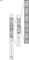
- FIG. 4 is a diagram showing a sequence for explaining the entire processing of the wireless communication system.
- the process shown in FIG. 4 is a process performed by AP1, AP2, and STAs.
- STAs indicate STA1 to STA4.
- the processing of the wireless communication system is divided into three phases: Assocaition Phase, RSSI Measurement Phase, and UL C-SR Tx Phase.
- Phase Ph1 is the Assocaition Phase.
- Assocaition Phase AP-STA connection processing within the same BSS and connection processing between APs for cooperative operation are performed.
- Assocaition Phase STA information in each BSS and Capability information of each AP and each STA are exchanged between APs.
- Phase Ph2 is RSSI Measurement Phase.
- RSSI Measurement Phase RSSI information between each AP and STA is measured and the propagation loss value of each link is calculated.
- a link is a resource such as a frequency band.
- the measuring method is not particularly limited, and the STA may measure the signal transmitted from the AP and feed it back, or the STA may transmit the signal and the AP may measure the signal. Further, the AP may constantly measure the received signal from each STA and calculate the propagation loss value from the statistical information.
- the AP can obtain information indicating the propagation loss value between at least all of its own STAs, but by exchanging information with other APs, the propagation loss information between the other APs and the STAs can be obtained. May be obtained.
- Phase Ph3 is UL C-SR Tx Phase.
- information is exchanged with AP2 before data transmission by AP1, the transmission method is determined based on the exchanged information, and the determined transmission method is the DL control signal Trigger Frame.
- BA are sent to STA by AP1 and AP2. At that time, STA performs UL transmission to AP1 and AP2.
- phase Ph3 is composed of steps S11 to S17.
- step S11 for example, after backoff, AP1 performs carrier sense, which is a process of detecting a carrier wave, and acquires a transmission opportunity based on the carrier sense result.
- step S12 AP1 transmits C-SR Announcement Frame, which is a signal requesting cooperative transmission of C-SR, to AP2.
- step S13 AP2 transmits C-SR Response Frame, which is a response signal of C-SR Announcement Frame.
- AP1 is a DL control signal based on Phase Ph1 and Phase Ph2, and the information exchanged here.
- step S14 AP1 transmits a MAP Trigger Frame including information indicating the determined transmission method to AP2.
- step S15 AP1 and AP2 transmit the Trigger Frame to the subordinate STA by the transmission method determined based on the MAP Trigger Frame.
- each STA under AP1 and AP2 performs UL transmission of DATAFrame to AP1 and AP2 based on the received TriggerFrame.
- step S17 AP1 and AP2 transmit BA to the STA that has performed UL transmission based on the MAP Trigger Frame.
- FIG. 5 is a diagram showing a frame configuration example of the C-SR Announcement Frame according to the first embodiment.
- the C-SR Announcement Frame is a frame transmitted from AP1 to AP2 in step S12 of FIG.
- the C-SR Announcement Frame is composed of FrameControl, Duration, RA, TA, DialogToken, SharingAPInfo, CandidateAPInfo.1, ..., CandidateAPInfo.n, and FCS fields.
- the field of Frame Control contains information indicating that this Frame is a C-SR Announcement Frame.
- the information indicating that this Frame is a frame for which cooperation is requested is included, and the information indicating that the cooperation method is C-SR in another field (for example, CoordinationType) is included. It may be included.
- the Duration field contains information indicating the transmission time of this Frame.
- the RA field contains the destination MAC (Media Access Control) address of this Frame. Normally, the transmission of this Frame is broadcast, but if there is only one Candidate AP Info described later, the MAC address of that AP may be shown.
- MAC Media Access Control
- the TA field contains the source MAC address of this Frame. Normally, the TA field contains the BSSID, which is the identification information of the BSS of the Sharing AP.
- the Dialog Token field contains the Token number of the process started by this Frame.
- the Sharing AP Info field contains information about Sharing AP.
- the Sharing AP Info field is composed of BW Info, Duration Info, UL / DL flag, and Sharing AP Info Variant sub fields.
- BWInfo subfield contains bandwidth information that has acquired a transmission opportunity.
- the subfield of DurationInfo contains the time information when the transmission opportunity was acquired.
- the UL / DL flag subfield contains information indicating whether it is UL cooperation or DL cooperation.
- Sharing AP Info Variant subfield contains different information depending on the cooperation method.
- at least the subfield of this Variant contains information on its own allowable interference power value (TolerableMaxInterferenceSignalStrengthInfo).
- Each Candidate AP Info field contains information about candidate APs that will be Shared APs.
- the Candidate APInfo field is composed of APID, CoordinationType, CCARequestInfo, ResponseSchedulingInfo, and CandidateAPInfoVariant subfields.
- the AP ID subfield contains the ID information of the candidate AP that will be a Shared AP.
- Coordination Type subfield contains information on how to collaborate. For example, in the present specification, C-SR is specified.
- the subfield of CCARequestInfo includes information on whether or not to implement CCA (ClearChannelAssessment), or information on the channel.
- CCA is synonymous with career sense.
- C-SR Response Scheduling Info's subfield contains C-SR Response scheduling information. For example, when there are multiple Candidate APs, the Sharing AP allocates resources to each AP so that the C-SR Response Frame is transmitted by OFDMA.
- the subfield of Candidate APInfoVariant contains different information depending on the cooperation method.
- at least this Variant includes the estimated value of the interference power (Estimated Interference Signal Strength Info) that the Candidate AP will receive in the UL transmission received by the Sharing AP.
- FCS Full Check Sequence
- FIG. 6 is a diagram showing a frame configuration example of the C-SR Response Frame according to the first embodiment.
- the C-SR Response Frame is a frame transmitted from AP2 to AP1 in step S13 of FIG.
- the C-SR Response Frame is composed of FrameControl, Duration, RA, TA, DialogToken, CCAResult, STAInfo1, ... STAInfon, and FCS fields.
- the field of Frame Control contains information indicating that this Frame is a C-SR Response Frame. Even if the information indicating that this Frame is a frame that responds to the cooperation request is included in the field of FrameControl, and the information indicating that the cooperation method is C-SR is included in other fields. good.
- the Duration field contains information indicating the transmission time of this Frame.
- the RA field contains the destination MAC address of this Frame. Normally, the RA field contains the BSSID, which is the identification information of the BSS of the Sharing AP.
- the TA field contains the source MAC address of this Frame. Normally, the TA field contains the BSSID, which is the identification information of the BSS of itself (Shared AP).
- the Dialog Token field contains the Token number of the process that this Frame responds to.
- the CCA Result field contains the CCA result (career sense result).
- the CCAResult field contains the result of performing CCA on each channel in response to the CCARequest requested by the Sharing AP. For example, when CCA of CH1 to CH4 is requested by CCA Request, Shared AP notifies each channel as "1" if it is in the Idle state and "0" if it is in the busy state.
- Sharing AP determines whether or not there is a possibility of frequency division based on the CCA Result of Shared AP. For example, if Primary CH is set to CH1 for both Sharing AP and Shared AP, and CH1 and adjacent CH2 are Idle for both Sharing AP / Shared AP, Sharing AP / Shared AP uses CH1 / CH2 and C-OFDMA. Is determined to be performed.
- Sharing AP temporarily switches the channel to CH2. Is determined.
- each STA Info contains information about the STA that induces UL transmission by itself.
- this field may include at least STAID information.
- the FCS field contains an error correction code.
- FIG. 7 is a diagram showing a frame configuration example of the MAP Trigger Frame.
- the MAP Trigger Frame is a frame transmitted from AP1 to AP2 in step S14 of FIG.
- the MAP Trigger Frame is composed of Frame Control, Duration, RA, TA, Dialog Token, Shared AP Info # 1, ..., Shared AP Info # n, and FCS fields.
- the field of Frame Control contains information indicating that this Frame is a MAP Trigger Frame.
- the Duration field contains information indicating the transmission time of this Frame.
- the RA field contains the destination MAC address of this Frame. Normally, the RA field contains the BSSID, which is the identification information of the BSS of the Shared AP.
- the TA field contains the source MAC address of this Frame. Normally, the TA field contains the BSSID, which is the identification information of the BSS of itself (Sharing AP).
- the Dialog Token field contains the Token number of the process that this Frame responds to.
- the field of each Shared AP Info contains information about the Shared AP that requests cooperation.
- the Shared APInfo field is composed of APID, CoordinationType, DLControlTxType, and DLControlTxVariant subfields.
- the AP ID field contains the Shared AP ID information.
- the Coordination Type field contains information on how to collaborate.
- the DLControlTxType field contains information on the transmission method of the DL control signal (only during UL transmission).
- the DLControlTxVariant field contains information according to the transmission method of the DL control signal. That is, the types of information included differ depending on the transmission method of the DL control signal.
- the bandwidth information (BWInfo) of the DL control signal the transmission power information (TxPowerInfo), the MCS information (MCSInfo), the frame length information (LengthInfo), and the transmission channel information (PCH) Info), resource information (RUInfo), TriggerFrame information (TriggerInfo) that the user is trying to send, etc. are included.
- Variant field may be transmitted in a form in which only one field is provided in the Frame separately from the Shared AP Info as Common Info.
- TriggerInfo includes both CommonInfo / UserInfo of IEEE802.11ax / TriggerFrame.
- the FCS field contains an error correction code.
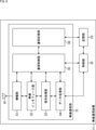
- FIG. 8 is a block diagram showing a configuration example of a wireless communication device.
- the wireless communication device 11 shown in FIG. 8 is a wireless communication device that operates as an AP (Sharing AP or Shared AP).
- the wireless communication device 11 is composed of a wireless communication unit 31, a control unit 32, a storage unit 33, and an antenna 41.
- the wireless communication unit 31 transmits and receives data.
- the wireless communication unit 31 is configured to include an amplification unit 51, a wireless interface unit 52, a signal processing unit 53, a data processing unit 54, a communication control unit 55, and a communication storage unit 56.
- the amplification unit 51 amplifies the analog signal supplied from the wireless interface unit 52 to a predetermined power, and outputs the amplified analog signal to the antenna 41.
- the amplification unit 51 amplifies the analog signal supplied from the antenna 41 to a predetermined electric power, and outputs the amplified analog signal to the wireless interface unit 52.
- a part of the function of the amplification unit 51 may be included in the wireless interface unit 52. Further, a part of the function of the amplification unit 51 may be a component outside the wireless communication unit 31.
- the wireless interface unit 52 converts the transmission symbol stream from the signal processing unit 53 into an analog signal, performs filtering, up-conversion to a carrier frequency, and phase control, and amplifies the analog signal after the phase control. Output to 51.
- the wireless interface unit 52 performs phase control, down-conversion, and reverse filtering on the analog signal supplied from the amplification unit 51, and outputs the received symbol stream as a result of converting to a digital signal to the signal processing unit 53. do.
- the signal processing unit 53 performs signal processing to be subjected to spatial separation on the data symbol stream supplied from the data processing unit 54, if necessary, and one or more obtained as a result of the signal processing.
- the transmission symbol stream is output to each wireless interface unit 52.
- the signal processing unit 53 performs signal processing on the received symbol stream supplied from each wireless interface unit 52, spatially separates the stream as necessary, and performs spatial separation of the stream, and the data symbol stream obtained as a result of the spatial separation. Is output to the data processing unit 54.
- the data processing unit 54 manages the sequence of the data held in the communication storage unit 56 and the control information and management information received from the communication control unit 55. Further, the data processing unit 54 generates a data unit by performing encryption processing of control information and management information, and adds a MAC header and an error detection code to the generated data unit, and a data unit. Perform multiple concatenation processing.
- the data processing unit 54 performs reconnection processing, analysis and error detection of the MAC header of the received data unit, and retransmission request reorder processing.
- the communication control unit 55 controls the operation of each unit of the wireless communication unit 31 and the information transmission between each unit. Further, the communication control unit 55 controls to pass control information and management information to be notified to other communication devices to the data processing unit 54.
- the communication control unit 55 exchanges information between APs and determines a transmission method of the DL control signal based on the exchanged information.
- the communication storage unit 56 holds information used by the communication control unit 55. Further, the communication storage unit 56 holds data to be transmitted and data to be received.
- the control unit 32 is composed of a CPU (Central Processing Unit), a ROM (Read Only Memory), a RAM (Random Access Memory), and the like.
- the control unit 32 executes a program stored in ROM or the like, and controls the wireless communication unit 31 and the communication control unit 55. Further, the control unit 32 may perform a part of the operation of the communication control unit 55 instead. Further, the communication control unit 55 and the control unit 32 may be configured as one block.
- the storage unit 33 holds information used by the wireless communication unit 31 and the control unit 32. Further, the storage unit 33 may perform a part of the operation of the communication storage unit 56 instead.
- the storage unit 33 and the communication storage unit 56 may be configured as one block.
- the wireless communication unit 31 is realized by one or more ICs, but the IC configuration of this technology is not limited to this.
- the wireless interface unit 52 may be configured as another IC.
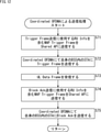
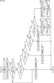
- FIG. 9 is a flowchart illustrating the processing of the Sharing AP (AP1) in the first embodiment.
- step S31 AP1 acquires a transmission opportunity (TXOP) (step S11 in FIG. 4).
- TXOP transmission opportunity
- step S32 AP1 transmits a C-SR Announcement Frame as a Sharing AP (step S12 in FIG. 4).
- Sharing AP the subject will be described as Sharing AP.
- step S33 the Sharing AP determines whether or not the C-SR Response Frame has been acquired from one or more Candidate APs. If it is determined in step S33 that the C-SR Response Frame has been acquired from one or more Candidate APs, the process proceeds to step S34.
- Shared AP is selected from the Candidate AP (AP2) that sent the C-SR Response Frame.
- step S34 the Sharing AP determines whether or not the DL control signal (DL Control Frame) can be transmitted Non-Duplicate based on the C-SR Response Frame.
- DL is performed in step S34. It is determined that the control signal can be transmitted Non-Duplicate.
- the permissible value is the SINR value that guarantees a PER (Packet Error Rate) below a certain level for MCS.
- the SINRs of all STAs that induce UL transmission in the Trigger are obtained, for example, in Phase Ph2 of FIG.
- the Sharing AP may adjust the transmission power value of each AP and the transmission parameters such as MCS so as to satisfy the above-mentioned allowable value.
- the adjusted transmission parameter is notified for each Shared AP as a MAP Trigger Frame in step S35 described later.
- step S34 If it is determined in step S34 that the DL control signal can be transmitted in a non-duplicate manner, the process proceeds to step S35.
- step S35 the Sharing AP transmits the MAP Trigger Frame to the Shared AP (step S14 in FIG. 4). After that, the process proceeds to step S36.
- step S33 If it is determined in step S33 that the C-SR Response Frame has not been acquired from one or more Candidate APs, the process proceeds to step S36.
- Sharing AP performs transmission processing by NonDuplicate.
- the transmission process by NonDuplicate will be described later with reference to FIG.
- the Sharing AP transmits the DL control signal in cooperation with the Shared AP by NonDuplicate, and receives the UL Data Frame from the STA.
- NonDuplicate here includes the fact that SharedAP does not exist and only AP1 sends TriggerFrame.
- step S34 If it is determined in step S34 that the DL control signal cannot be transmitted in a non-duplicate manner, the process proceeds to step S37.
- step S37 the Sharing SP determines whether or not the DL control signal can be transmitted by FDD (Frequency Division Duplex), that is, by the frequency division method.
- FDD Frequency Division Duplex
- step S37 it is determined in step S37 that the DL control signal cannot be transmitted by FDD, and the process proceeds to step S38.
- Sharing AP performs transmission processing by Duplicate.
- the transmission process by Duplicate will be described later with reference to FIG.
- Sharing AP transmits DL control signal in cooperation with Shared AP by Duplicate, and receives UL Data Frame from STA.
- step S37 If it is determined in step S37 that the DL control signal can be transmitted by FDD, the process proceeds to step S39.
- step S39 Sharing AP determines whether or not Coordinated OFDMA is possible. For this determination, the Capability information acquired in the phase Ph1 of FIG. 4 and the CCA Result of the C-SR Response Frame are used.
- step S37 it is determined in step S37 that Coordinated OFDM is possible, and the process is performed in step S40. Proceed to.
- Sharing AP performs transmission processing by Coordinated OFDMA.
- the transmission process by Coordinated OFDMA will be described later with reference to FIG.
- the Sharing AP transmits the DL control signal in cooperation with the Shared AP by Coordinated OFDMA, and receives the UL Data Frame from the STA.
- step S39 If it is determined in step S39 that Coordinated OFDMA is not possible, the process proceeds to step S41.
- step S41 the Sharing AP determines whether or not it performs Channel Switching.
- step S41 if the Primary Channel (PCH) of the Shared AP is in the "Busy" state based on the CCA Result of the C-SR Response Frame, it is determined in step S41 that the channel switching itself is performed, and the process is step S42. Proceed to.
- PCH Primary Channel
- step S42 the Sharing AP transmits a MAP Trigger Frame including the PCH Info indicating the current PCH to the Shared AP.
- Sharing AP performs transmission processing by its own Channel Switching.
- the transmission process by its own Channel Switching will be described later with reference to FIG.
- the Sharing AP transmits the DL control signal in cooperation with the Shared AP by its own Channel Switching, and receives the UL Data Frame from the STA.
- step S41 if the Primary Channel of the Shared AP is in the "Busy" state based on the CCA Result of the C-SR Response Frame, it is determined in step S41 that the channel switching itself is not performed, and the process proceeds to step S44. ..
- step S44 the Sharing AP transmits a MAP Trigger Frame including the PCH Info indicating the CH after switching to the Shared AP.
- step S45 the Sharing AP performs transmission processing by Channel Switching of another AP (in this case, Shared AP).
- the transmission process by Channel Switching of other APs will be described later with reference to FIG.
- the Sharing AP transmits the DL control signal in cooperation with the Shared AP by the Channel Switching of the Shared AP, and receives the UL Data Frame from the STA.
- FIG. 10 is a flowchart illustrating a transmission process by NonDuplicate in step S36 of FIG.
- step S51 the Sharing AP transmits a Trigger Frame to the STA in its own BSS (step S15 in FIG. 4).
- the STA specified by Trigger Frame sends UL Data Frame (step S16 in FIG. 4).
- step S52 the Sharing AP receives the UL Data Frame transmitted from the STA.
- step S53 Sharing AP sends BA to STA in its own BSS.
- FIG. 11 is a flowchart illustrating a transmission process by Duplicate in step S38 of FIG.
- Sharing AP needs to acquire Trigger Info from Shared AP. Therefore, in step S61, the Sharing AP transmits a MAP Trigger Frame including the Trigger Info addressed to the STA in its own BSS to the Shared AP (step S14 in FIG. 4).
- step S62 the Sharing AP receives a Response Frame including a Trigger Info addressed to the STA in the BSS of the Shared AP from the Shared AP.
- step S63 the Sharing AP transmits a Trigger Frame containing information on all STAs that induce UL transmission to the STAs in its own BSS and in the BSS of the Shared AP (step S15 in FIG. 4).
- the STA specified by Trigger Frame sends UL Data Frame (step S16 in FIG. 4).
- step S64 the Sharing AP receives the UL Data Frame transmitted from the STA.
- step S65 Sharing AP transmits BA to STA in its own BSS (step S17 in FIG. 4).
- step S66 the Sharing AP waits for the transmission of the BA of the Shared AP.
- FIG. 12 is a flowchart illustrating a transmission process by Coordinated OFDMA in step S40 of FIG.
- MAP Trigger is transmitted even before BA transmission because Sharing AP establishes synchronization with Shared AP.
- step S71 the Sharing AP transmits a MAP Trigger Frame including RUInfo, which is resource information used for Trigger Frame transmission (step S14 in FIG. 4).
- step S72 the Sharing AP transmits a Trigger Frame to the STA in its own BSS by Coordinated OFDMA (step S15 in FIG. 4).
- step S73 the Sharing AP receives the UL Data Frame.
- step S74 the Sharing AP transmits a MAP Trigger Frame including the RU Info used for BA transmission to the Shared AP.
- step S75 Sharing AP transmits BA to STA in its own BSS by Coordinated OFDMA (step S17 in FIG. 4).
- FIG. 13 is a flowchart illustrating a transmission process to its own Channel Swiching in step S43 of FIG.
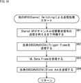
- Sharing AP or Shared AP sends a channel switching request signal indicating channel switching to the subordinate STA, and then sends a Trigger Frame to induce UL transmission. ..
- the channel switching request signal may be included in the MAP Trigger.
- step S81 the Sharing AP transmits a channel switching request signal to the STA in its own BSS.
- step S82 the Sharing AP transmits a Trigger Frame to the STA in its own BSS on the switched channel (step S15 in FIG. 4).
- step S83 the Sharing AP receives the UL Data Frame.
- step S84 the Sharing AP transmits BA to the STA in its own BSS on the switched channel (step S17 in FIG. 4).
- FIG. 14 is a flowchart illustrating a transmission process to Channel Swiching of another AP in step S45 of FIG.
- step S91 the Sharing AP waits until the Shared AP finishes transmitting the channel switching request signal.
- step S92 the Sharing AP transmits a Trigger Frame to the STA in its own BSS (step S15 in FIG. 4).
- step S93 the Sharing AP receives the UL Data Frame.
- step S94 the Sharing AP transmits BA to the STA in its own BSS on the switched channel (step S17 in FIG. 4).
- FIG. 15 is a flowchart illustrating the processing of Shared AP (AP2) in the first embodiment.
- process of FIG. 15 is the process at the time of receiving the C-SR Announcement Frame transmitted in step S12 of FIG.
- step S101 AP2 receives the C-SR Announcement Frame.
- step S102 AP2 determines whether or not it has its own APID and whether or not UL can cooperate based on the C-SR Announcement Frame. If it is determined in step S102 that there is its own APID and UL cooperation is possible, the process proceeds to step S103.
- step S103 AP2 performs UL scheduling as a Shared AP.
- UL scheduling is the process of allocating resources to the STA and the process of setting the transmit power value so that it is less than or equal to the allowable interference power value of Sharing AP.
- Shared AP the subject will be described as Shared AP.
- step S104 the Shared AP transmits a C-SR Response Frame.
- step S105 the Shared AP waits for the MAP Trigger Frame from the Sharing AP.
- step S102 If it is determined in step S102 that there is no own APID or UL cooperation is not possible, the process proceeds to step S106.
- step S106 AP2 sets NAV (Network Allocation Vector, transmission prohibition period).
- step S105 or S106 the process of FIG. 15 ends.
- FIG. 16 is a flowchart illustrating the processing of Shared AP (AP2) in the first embodiment.
- FIG. 16 is the process at the time of receiving the MAP Trigger Frame transmitted in step S14 of FIG.
- step S131 the Shared AP receives the MAP Trigger Frame.
- step S132 the Shared AP determines whether or not the DLControlTxType included in the MAPTriggerFrame is NonDuplicate. If it is determined in step S132 that DLControlTxType is NonDuplicate, the process proceeds to step S133.
- step S133 the Shared AP performs a transmission process by NonDuplicate.
- the transmission process by NonDuplicate is the same process as the above-described process with reference to FIG.
- the Shared AP transmits the DL control signal in cooperation with the Sharing AP by NonDuplicate, and receives the UL Data Frame from the STA.
- step S132 If it is determined in step S132 that DLControlTxType is not NonDuplicate, the process proceeds to step S134.
- step S134 the Shared AP determines whether or not the DLControlTxType is Duplicate. If it is determined in step S134 that DLControlTxType is Duplicate, the process proceeds to step S135.
- step S135 the Shared AP sends a Response Frame including a Trigger Info addressed to the STA in its own BSS to the Sharing AP.
- step S136 the Shared AP performs a transmission process by Duplicate.
- the transmission process by Duplicate will be described later with reference to FIG.
- the Shared AP transmits the DL control signal in cooperation with the Sharing AP by Duplicate, and receives the UL Data Frame from the STA.
- step S134 If it is determined in step S134 that DLControlTxType is not Duplicate, the process proceeds to step S137.
- step S137 the Shared AP determines whether or not the DLControlTxType is CoordinatedOFDMA. If it is determined in step S137 that DLControlTxType is CoordinatedOFDMA, the process proceeds to step S138.
- step S138 the Shared AP performs a transmission process by Coordinated OFDMA.
- the transmission process by Coordinated OFDMA will be described later with reference to FIG.
- the Shared AP transmits the DL control signal in cooperation with the Sharing AP by Coordinated OFDMA, and receives the UL Data Frame from the STA.
- step S137 If it is determined in step S137 that DLControlTxType is not CoordinatedOFDMA, the process proceeds to step S139.
- step S139 the Shared AP determines whether or not the PCHInfo included in the MAPTriggerFrame is the current PCH. If it is determined in step S139 that the PCHInfo included in the MAPTriggerFrame is not the current PCH, the process proceeds to step S140.
- step S140 the Shared AP performs transmission processing by its own Channel Switching.
- the transmission process by its own Channel Switching is the same process as the process described above with reference to FIG.
- the Shared AP transmits the DL control signal in cooperation with the Sharing AP by its own Channel Switching, and receives the UL Data Frame from the STA.
- step S139 If it is determined in step S139 that the PCHInfo included in the MAPTriggerFrame is the current PCH, the process proceeds to step S141.
- step S141 the Shared AP performs transmission processing by Channel Switching of another AP (in this case, Sharing AP).
- the transmission process by Channel Switching of other APs will be described later with reference to FIG.
- the Shared AP transmits the DL control signal in cooperation with the Sharing AP by Channel Switching of the other AP, and receives the UL Data Frame from the STA.
- FIG. 17 is a flowchart illustrating a transmission process by Duplicate in step S136 of FIG.
- step S161 the Shared AP transmits a Trigger Frame to the STA in its own BSS and in the BSS of the Sharing AP.
- the STA specified by Trigger Frame sends UL Data Frame.
- step S162 the Shared AP receives the UL Data Frame transmitted from the STA.
- step S163 the Shared AP waits for the transmission of the BA of the Sharing AP.
- step S164 the Shared AP sends a BA to the STA in its own BSS.
- FIG. 18 is a flowchart illustrating a transmission process by Coordinated OFDMA in step S138 of FIG.
- step S181 the Shared AP transmits a Trigger Frame to the STA in its own BSS by Coordinated OFDMA.
- step S182 the Shared AP receives the UL Data Frame.
- the Sharing AP sends the MAP Trigger Frame including the RU Info used for BA transmission to the Shared AP.
- step S183 the Shared AP receives the MAP Trigger Frame.
- step S184 the Shared AP transmits BA to the STA in its own BSS by Coordinated OFDMA.
- FIG. 19 is a flowchart illustrating a transmission process to Channel Swiching of another AP in step S141 of FIG.
- step S191 the Shared AP waits until the Sharing AP finishes transmitting the channel switching request signal.
- step S192 the Shared AP sends a Trigger Frame to the STA in its own BSS.
- step S193 the Shared AP receives the UL Data Frame.
- step S194 the Shared AP transmits BA to the STA in its own BSS on the switched channel.
- FIG. 20 is a diagram showing the effect of the first embodiment of the present technology.
- FIGS. 20A to 20D an image of a frame sequence by each transmission method of Duplicate, Channel Switching, Coordinated OFDMA, and NonDuplicate and the time required for them is shown in order.
- hatching is performed on a frame or a part of the frame whose required time is increased as compared with other transmission methods.
- Channel Switching in FIG. 20B, an additional signal (Channel Switch Request Frame) for channel switching is required, and the number of frames increases.
- Channel Switch Request Frame In the case of Coordinated OFDMA of C in FIG. 20, MAP Trigger Frame transmission before BA is additionally required, and the number of frames increases.
- NonDuplicate of D in FIG. 20 the number of frames required is the smallest, and since Trigger and BA can be transmitted in a wide band, it can be expected that the frame transmission time will be shorter than other methods.
- the transmission of NonDuplicate is prioritized and the transmission method of the DL control signal is determined. Therefore, the transmission time (that is, overhead) of the control signal with respect to the data transmission time can be shortened. can.
- Sharing AP can only transmit in the 20MHz band
- DL control to all STAs can be performed while reducing the overhead as much as possible by using Duplicate and NonDuplicate other than Channel Switching and Coordinated OFDMA.
- the transmission of signals can be guaranteed.
- one transmission method is determined from two or three transmission methods among the four transmission methods. You may try to do it.
- the sharing AP determines the transmission method of the DL control signal.
- the Sharing AP in order for the Sharing AP to determine whether or not the DL control signal can be transmitted by, for example, Duplicate, the Sharing AP needs to know the information necessary for the transmission decision.
- the information required for transmission determination is the propagation loss value between all APs and all STAs acquired in the phase Ph2 (RSSI Measurement Phase) of FIG. 4 and the phase Ph1 (Assocaition Phase) described above. Capability information of AP and STA to be acquired, CCA Result (information indicating carrier sense result) acquired by C-SR Response Frame, etc.
- the transmission method of the DL control signal is determined based on information exchange between the Sharing AP and the Shared AP.
- the Sharing AP finally determines the optimum transmission method based on the transmission method determined by the Shared AP.
- the Sharing AP can obtain at least the transmission loss information between all APs and all STAs without knowing the transmission loss value between all APs and all STAs. , It can be determined whether or not the DL control signal can be Duplicate transmitted.
- the Shared AP determines the transmission method of the DL control signal, in the above-mentioned C-SR Response, the determined DL control signal transmission method and the information required according to the transmission method are transmitted from the Shared AP to the Sharing AP. Can be transmitted to. Therefore, in the second embodiment, depending on the transmission method, it is not necessary to transmit another frame for transmitting necessary information depending on the transmission method, so that it is compared with the first embodiment. , It is possible to further shorten the overhead.
- the entire processing sequence is basically the same as the entire processing sequence of the first embodiment described above with reference to FIG.
- the second embodiment a part different from the first embodiment will be described.
- FIG. 21 is a diagram showing a frame configuration example of the C-SR Announcement Frame in the second embodiment.
- FIG. 21 is a field containing information characteristic of the present technology, and shows that it is a part different from the case of the first embodiment. The same applies to the subsequent figures in the second embodiment.
- DLControlFrameInfo is included in Sharing APInfoVariant and CandidateAPInfoVariant, and here, the transmission parameters used by each AP for transmission of DL control signal.
- a certain bandwidth (BWInfo), transmission power information (TxPowerInfo) and MCS information (MCSInfo) are stored.
- the Shared AP which will be described later with reference to FIG. 23, determines the transmission method of the DL control signal using these transmission parameters.
- the Shared AP also sets the transmission parameter of the DL control signal based on the DLControlFrameInfo in the SharingAPInfoVariant.
- FIG. 22 is a diagram showing a frame configuration example of the C-SR Response Frame in the second embodiment.
- the difference from the first embodiment is that the DlControlTxType information is included in the Frame, and not only the STAID but also the Shared AP is transmitted to the STA in the STAInfo. It is possible to include the Trigger Info that is planned to be used.
- the information contained in this field differs depending on the transmission method of the DL control signal determined by Shared AP. Further, depending on the transmission method of the DL control signal determined by the Shared AP, the STA Info itself may not be notified.
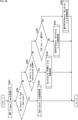
- FIG. 23 is a flowchart illustrating the processing of the Sharing AP (AP1) in the second embodiment.
- FIG. 23 the differences from the first embodiment (FIG. 9) are as follows.
- the transmission method of the DL control signal is determined by each Shared AP, and is finally determined by the Sharing AP based on the DL Control Tx Type in the C-SR Response returned from the Shared AP.
- Sharing AP When sending by Non Duplicate, Sharing AP does not send MAP Trigger, but sends Trigger Frame to STA in the same BSS as it is. This is because the transmission parameters of Trigger / BA are already shared between Sharing AP and Shared AP, and it has been confirmed that there is no problem even if they are transmitted at the same time.
- Sharing AP transmits Trigger Frame to STA in the same BSS after MAP Trigger transmission (Shared AP receives MAP Trigger). This is because the Shared AP responds by including the Trigger Info in the C-SR Response, so if the Trigger Info of the Sharing AP is shared in the MAP Trigger, duplicate transmission becomes possible.
- step S201 of FIG. 23 AP1 acquires a transmission opportunity (TXOP).
- step S202 AP1 transmits a C-SR Announcement Frame as a Sharing AP.
- Sharing AP the subject will be described as Sharing AP.
- step S203 the Sharing AP determines whether or not the C-SR Response Frame has been acquired from one or more Candidate APs. If it is determined in step S203 that the C-SR Response Frame has been acquired from one or more Candidate APs, the process proceeds to step S204.
- the Shared AP is selected from the Candidate APs that have sent the C-SR Response Frame.
- step S204 the Sharing AP determines whether or not the DLControlTxType of the C-SRResponseFrame is NonDuplicate. If it is determined in step S204 that DLControlTxType is NonDuplicate, the process proceeds to step S205.
- step S203 Even if it is determined in step S203 that the C-SR Response Frame has not been acquired from one or more Candidate APs, the process proceeds to step S205.
- Sharing AP performs transmission processing by NonDuplicate.
- the transmission process by NonDuplicate is the same process as the above-described process with reference to FIG.
- the Sharing AP transmits the DL control signal in cooperation with the Shared AP by NonDuplicate, and receives the UL Data Frame from the STA.
- NonDuplicate here includes the fact that SharedAP does not exist and only AP1 sends TriggerFrame.
- step S204 If it is determined in step S204 that DLControlTxType is not NonDuplicate, the process proceeds to step S206.
- step S206 the Sharing AP determines whether or not the DLControlTxType of the C-SRResponseFrame is Duplicate. If it is determined in step S206 that DLControlTxType is Duplicate, the process proceeds to step S207.
- Sharing AP performs transmission processing by Duplicate.
- the transmission process by Duplicate will be described later with reference to FIG. 24.
- Sharing AP transmits DL control signal in cooperation with Shared AP by Duplicate, and receives UL Data Frame from STA.
- step S206 if the Sharing AP determines that the DLControlTxType of the C-SRResponseFrame is not Duplicate, the process proceeds to step S208.
- step S208 the Sharing AP determines whether or not the DLControlTxType of the C-SRResponseFrame is CoordinatedOFDMA. If it is determined in step S208 that DLControlTxType is CoordinatedOFDMA, the process proceeds to step S209.
- Sharing AP performs transmission processing by Coordinated OFDMA.
- the transmission process by Coordinated OFDMA is the same process as the process described above with reference to FIG.
- the Sharing AP transmits the DL control signal in cooperation with the Shared AP by Coordinated OFDMA, and receives the UL Data Frame from the STA.
- step S208 If it is determined in step S208 that DLControlTxType is not capable of coordinated OFDMA, the process proceeds to step S210.
- step S210 the Sharing AP determines whether or not it performs Channel Switching. If it is determined in step S210 that the user performs Channel Switching, the process proceeds to step S211.
- step S211 the Sharing AP transmits a MAP Trigger Frame including the PCH Info indicated by the current PCH to the Shared AP.
- step S212 the Sharing AP performs transmission processing by its own Channel Switching.
- the transmission process by its own Channel Switching is the same process as the process described above with reference to FIG.
- the Sharing AP transmits the DL control signal in cooperation with the Shared AP by its own Channel Switching, and receives the UL Data Frame from the STA.
- step S210 If it is determined in step S210 that it does not perform Channel Switching, the process proceeds to step S213.
- step S213 the Sharing AP transmits a MAP Trigger Frame including PCH Info indicating the CH after switching to the Shared AP.
- step S214 the Sharing AP performs transmission processing by Channel Switching of another AP (in this case, Shared AP).
- the transmission process by Channel Switching of the other AP is the same process as the process described above with reference to FIG.
- the Sharing AP transmits the DL control signal in cooperation with the Shared AP by the Channel Switching of the Shared AP, and receives the UL Data Frame from the STA.
- FIG. 23 an example in which the Sharing AP determines the transmission method based on the DLControlTxType of the C-SRResponseFrame is shown, but when the transmission method of the DL control signal is other than NonDuplicate, The transmission method may be determined by its own determination. That is, in the MAP Trigger Frame, a DL Control Tx Type different from the Shared AP may be specified for transmission.
- FIG. 24 is a flowchart illustrating a transmission process by Duplicate in step S207 of FIG. 23.
- step S231 the Sharing AP sends a MAP Trigger Frame including a Trigger Info addressed to the STA in its own BSS to the Shared AP.
- step S232 the Sharing AP transmits a Trigger Frame to the STA in its own BSS and in the BSS of the Shared AP.
- the STA specified by Trigger Frame sends UL Data Frame.
- step S233 the Sharing AP receives the UL Data Frame transmitted from the STA.
- step S234 the Sharing AP sends a BA to the STA in its own BSS.
- step S235 the Sharing AP waits for the transmission of the BA of the Shared AP.
- BA is Trigger Frame.
- it may be transmitted as a Duplicate Frame.
- FIG. 25 is a flowchart illustrating the processing of Shared AP (AP2) in the second embodiment.
- process of FIG. 25 is the process at the time of receiving the C-SR Announcement Frame transmitted in step S12 of FIG.
- the difference from the first embodiment (FIG. 15) is that after UL scheduling, the Shared AP determines and determines the transmission method of the DL control signal based on the acquired information, and the DL in the C-SR Response. It is a point to notify in TxType.
- the information required for each determination is the information acquired in Phase Ph1 or Phase Ph2 of the previous stage or notified by the C-SR Announcement Frame.
- step S251 of FIG. 25 AP2 receives the C-SR Announcement Frame.
- step S252 AP2 determines whether or not it has its own APID and whether or not UL can cooperate based on the C-SR Announcement Frame. If it is determined in step S252 whether or not there is its own AP ID and UL cooperation is possible, the process proceeds to step S253.
- step S253 AP2 performs UL scheduling as a Shared AP.
- step S252 If it is determined in step S252 that there is no own APID or UL cooperation is not possible, the process proceeds to step S254.
- step S254 AP2 sets the NAV. After step S254, the process of FIG. 25 ends.
- step S253 the process proceeds to step S255.
- the subject will be described as Shared AP.
- step S255 the Shared AP determines whether or not the DL control signal can be transmitted Non-Duplicate.
- the SINR of the STA in the same BSS that they are trying to induce UL transmission with Trigger Frame is the allowable value.
- the SINR of the STA in the same BSS that itself is trying to induce UL transmission in the Trigger Frame is acquired, for example, in Phase Ph2 of FIG.
- step S255 If it is determined in step S255 that the DL control signal can be transmitted in a non-duplicate manner, the process proceeds to step S256.
- step S257 the Shared AP transmits a Trigger Frame after SIFS.
- step S255 If it is determined in step S255 that the DL control signal cannot be transmitted in a non-duplicate manner, the process proceeds to step S258.
- step S258 the Shared AP determines whether or not the DL control signal can be transmitted by FDD.
- step S258 if the Sharing AP has acquired a transmission opportunity with a bandwidth of 40 MHz or more, it is determined in step S258 that the DL control signal cannot be transmitted by FDD, and the process is performed in step S259. move on.
- step S259 the Shared AP transmits a C-SR Response Frame containing Trigger Info in the STA Info to the Sharing AP with the DLControlType being Duplicate.
- step S258 If it is determined in step S258 that the Shared AP can transmit the DL control signal by FDD, the process proceeds to step S260.
- step S260 the Shared AP determines whether or not Coordinated OFDMA is possible. For this determination, the Capability information acquired in Phase Ph1 of FIG. 4 and its own carrier sense result are used.
- step S260 If Coordinated OFDM is feasible in the Capability information acquired in Phase Ph1 of FIG. 4 for both Sharing AP and Shared AP, it is determined in step S260 that Coordinated OFDM is possible, and the process proceeds to step S261. ..
- step S261 the Shared AP transmits a C-SR Response Frame containing the STA ID in the STA Info to the Sharing AP with the DLControlType being CoordinatedOFDMA.
- step S260 If it is determined in step S260 that Coordinated OFDMA is not possible, the process proceeds to step S262.
- step S262 the Shared AP transmits a C-SR Response Frame whose DL Control Type is Channel Switching to the Sharing AP based on its own carrier sense result.
- step S259, S261, or S262 the process proceeds to step S263.
- step S263 the Shared AP waits for the MAP Trigger Frame from the Sharing AP.
- step S257 or S263 the process of FIG. 25 ends.
- FIG. 26 is a flowchart illustrating another process of Shared AP (AP2) in the second embodiment.
- FIG. 26 is the process at the time of receiving the MAP Trigger Frame transmitted in step S14 of FIG.
- step S281 of FIG. 26 the Shared AP receives the MAP Trigger Frame.
- step S282 the Shared AP determines whether or not the DLControlTxType included in the MAPTriggerFrame is Duplicate. If it is determined in step S282 that DLControlTxType is Duplicate, the process proceeds to step S283.
- step S283 the Shared AP performs transmission processing by Duplicate.
- the transmission process by Duplicate is the same process as the process described above with reference to FIG.
- the Shared AP transmits the DL control signal in cooperation with the Sharing AP by Duplicate, and receives the UL Data Frame from the STA.
- the Shared AP responds by including the Trigger Info in the C-SR Response, and the Trigger Info of the Sharing AP is shared in the MAP Trigger, so that duplicate transmission is possible. It has become.
- step S282 If it is determined in step S282 that DLControlTxType is not Duplicate, the process proceeds to step S284.
- step S284 the Shared AP determines whether or not the DLControlTxType is CoordinatedOFDMA. If it is determined in step S284 that DLControlTxType is CoordinatedOFDMA, the process proceeds to step S285.
- step S285 the Shared AP performs a transmission process by Coordinated OFDMA.
- the transmission process by Coordinated OFDMA is the same process as the process described above with reference to FIG.
- the Shared AP transmits the DL control signal in cooperation with the Sharing AP by Coordinated OFDMA, and receives the UL Data Frame from the STA.
- step S284 If it is determined in step S284 that DLControlTxType is not CoordinatedOFDMA, the process proceeds to step S286.
- step S286 the Shared AP determines whether or not the PCHInfo included in the MAPTriggerFrame is the current PCH. If it is determined in step S286 that the PCHInfo included in the MAPTriggerFrame is not the current PCH, the process proceeds to step S287.
- step S287 the Shared AP performs transmission processing by its own Channel Switching.
- the transmission process by its own Channel Switching is the same process as the process described above with reference to FIG.
- the Shared AP transmits the DL control signal in cooperation with the Sharing AP by its own Channel Switching, and receives the UL Data Frame from the STA.
- step S286 If it is determined in step S286 that the PCHInfo included in the MAP Trigger Frame is the current PCH, the process proceeds to step S288.
- step S288 the Shared AP performs transmission processing by Channel Switching of another AP (in this case, Sharing AP).
- the transmission process by Channel Switching of the other AP is the same process as the process described above with reference to FIG.
- the Shared AP transmits the DL control signal in cooperation with the Sharing AP by Channel Switching of the other AP, and receives the UL Data Frame from the STA.
- FIG. 27 is a diagram showing the effect of the second embodiment of the present technology.
- FIGS. 27A to 27D an image of a frame sequence by each method of Duplicate, Channel Switching, Coordinated OFDMA, and NonDuplicate and the time required for them is shown in order.
- the frames that are increased as compared with the other methods are hatched.
- the DL control signal transmission method determined by Sharing in the first embodiment is determined by the Shared AP in the second embodiment.
- the number of frames exchanged during transmission by Duplicate or transmission by NonDuplicate can be reduced from the example of FIG. 20.
- NonDuplicate in FIG. 27 since it is not necessary to replace the MAP Trigger Frame, the number of frames exchanged during transmission by NonDuplicate can be further reduced as compared with the example in FIG. 20, and overhead reduction can be expected.
- the Shared AP requests the control of the transmission parameter (mainly the transmission power) of the DL control signal of the Sharing AP, so that the DL control signal is more Non. Opportunities for Duplicate transmission can be increased.
- the entire processing sequence is basically the same as the entire processing sequence of the first embodiment described above with reference to FIG.
- the parts different from those in the first and second embodiments will be described.
- FIG. 28 is a diagram showing a frame configuration example of the C-SR Announcement Frame according to the third embodiment.
- FIG. 28 is a field containing information characteristic of the present technology, and indicates that it is a part different from the case of the first and second embodiments. The same applies to the subsequent figures in the third embodiment.
- the difference from the second embodiment is that the DLControlFrameAdjustmentTypefield is added in the DLControlFrameInfo of the SharingAPInfoVariant.
- the Sharing AP writes information about whether or not the transmission parameter of its DL control signal can be adjusted in this field, and notifies the Shared AP.
- FIG. 29 is a diagram showing a frame configuration example of the C-SR Response Frame according to the third embodiment.
- the difference from the second embodiment is that DlControlTxParameterReqfield is added in this Frame, and the Shared AP is the allowable transmission power information of the DL control signal transmitted by the Sharing AP.
- the point is to request the Sharing AP to control the transmission power.
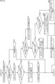
- FIG. 30 is a flowchart illustrating the processing of the Sharing AP (AP1) in the third embodiment.
- the transmission parameter changeable here is the requested transmission parameter, and the STA that induces UL transmission in its own BSS can receive the DL control signal without any problem (that is, the SINR estimate satisfies the required value). Means that.
- step S301 of FIG. 30 AP1 acquires a transmission opportunity (TXOP).
- step S302 AP1 transmits a C-SR Announcement Frame as a Sharing AP.
- Sharing AP the subject will be described as Sharing AP.
- step S303 the Sharing AP determines whether or not the C-SR Response Frame has been acquired from one or more Candidate APs. If it is determined in step S303 that the C-SR Response Frame has been acquired from one or more Candidate APs, the process proceeds to step S304.
- the Shared AP is selected from the Candidate APs that have sent the C-SR Response Frame.
- step S304 the Sharing AP determines whether or not the DLControlTxType of the C-SRResponseFrame is NonDuplicate. If it is determined in step S304 that DLControlTxType is not NonDuplicate, the process proceeds to step S305.
- step S305 Sharing AP determines whether or not there is a transmission parameter control request and it can be changed. If it is determined in step S305 that there is a transmission parameter control request and it can be changed, the process proceeds to step S306.
- step S306 the Sharing AP includes the transmission parameter information of the Trigger Frame for transmission to the STA in its own BSS, and transmits the MAP Trigger Frame with the DL Tx Type as Non Duplicate. After that, the process proceeds to step S307.
- step S303 Processing even when it is determined in step S303 that the C-SR Response Frame has not been acquired from one or more Candidate APs, or when it is determined in step S304 that the DLControlTxType is NonDuplicate. Goes to step S307.
- Sharing AP performs transmission processing by NonDuplicate.
- the transmission process by NonDuplicate is the same process as the above-described process with reference to FIG.
- the Sharing AP transmits the DL control signal in cooperation with the Shared AP by NonDuplicate, and receives the UL Data Frame from the STA.
- NonDuplicate here includes the fact that SharedAP does not exist and only AP1 sends TriggerFrame. After that, the process of FIG. 30 ends.
- step S305 If it is determined in step S305 that there is no transmission parameter control request or it cannot be changed, the process proceeds to step S308.
- steps S308 to S316 in FIG. 30 are basically the same as the processes of steps S206 to S214 of FIG. 23, the description thereof will be repeated and will be omitted.
- FIG. 31 is a flowchart illustrating the processing of Shared AP (AP2) in the third embodiment.
- the process of FIG. 31 is the process at the time of receiving the C-SR Announcement Frame transmitted in step S12 of FIG.
- steps S351 to S354, S356, S357, and steps S360 to S365 in FIG. 31 is basically the same as the processing of steps S251 to S257 and steps S258 to S263 in FIG. It will be repeated, so it will be omitted.
- step S355 of FIG. 31 If it is determined in step S355 of FIG. 31 that the DL control signal cannot be transmitted in a non-duplicate manner, the process proceeds to step S358.
- step S358 the Shared AP determines whether or not to request the change of the transmission parameter to the Sharing AP. If it is determined in step S358 that the change of the transmission parameter to the Sharing AP is requested, the process proceeds to step S359.
- step S359 the Shared AP sets DLControlTxParameterReq. After that, the process proceeds to step S360.
- step S359 determines whether the change of the transmission parameter to the Sharing AP is not requested. If it is determined in step S359 that the change of the transmission parameter to the Sharing AP is not requested, the process proceeds to step S360.
- the Shared AP determines that the non-Duplicate transmission of the DL control signal is impossible, and then the Non-Duplicate transmission is possible by changing the transmission parameter of the Sharing AP, the DL of the C-SR Response.
- the process proceeds to the determination of another transmission method as in the case of the second embodiment.
- NonDuplicate transmission is not possible even if the transmission parameter of Sharing AP is changed, or if Sharing AP does not allow its own transmission parameter control (DL Control Frame Adjustment Type in C-SR Announcement).
- the notification also shifts to the determination of another transmission method as in the case of the second embodiment.
- FIG. 32 is a diagram showing the effect of the third embodiment of the present technology.
- FIG. 32 the frame sequence by each method of Duplicate, Channel Switching, Coordinated OFDMA, NonDuplicate, and NonDuplicate (with change of transmission parameter) and An image of the time required for them is shown.
- FIG. 32 the frames that are increased as compared with the other methods are hatched.
- the case of changing the transmission parameter and performing Non-Duplicate transmission (D'in FIG. 32) can be newly selected.
- uplink transmission which is transmission from a wireless communication terminal, is performed in cooperation with other wireless communication devices. Further, transmission method information indicating a transmission method of the downlink control signal, which is a control signal required for uplink transmission, or information necessary for determining the transmission method is acquired from another wireless communication device.
- the transmission time (that is, overhead) of the control signal with respect to the data transmission time can be shortened.
- FIG. 33 is a block diagram showing a configuration example of computer hardware that executes the above-mentioned series of processes programmatically.
- the CPU Central Processing Unit
- ROM Read Only Memory
- RAM Random Access Memory
- the input / output interface 305 is further connected to the bus 304.
- An input unit 306 including a keyboard, a mouse, and the like, and an output unit 307 including a display, a speaker, and the like are connected to the input / output interface 305.
- the input / output interface 305 is connected to a storage unit 308 made of a hard disk, a non-volatile memory, etc., a communication unit 309 made of a network interface, etc., and a drive 310 for driving the removable media 311.
- the CPU 301 loads the program stored in the storage unit 308 into the RAM 303 via the input / output interface 305 and the bus 304, and executes the above-mentioned series of processes. Is done.
- the program executed by the CPU 301 is recorded on the removable media 311 or provided via a wired or wireless transmission medium such as a local area network, the Internet, or digital broadcasting, and installed in the storage unit 308.
- the program executed by the computer may be a program in which processing is performed in chronological order according to the order described in the present specification, in parallel, or at a necessary timing such as when a call is made. It may be a program in which processing is performed.
- the system means a set of a plurality of components (devices, modules (parts), etc.), and it does not matter whether all the components are in the same housing. Therefore, a plurality of devices housed in separate housings and connected via a network, and a device in which a plurality of modules are housed in one housing are both systems. ..
- this technology can take a cloud computing configuration in which one function is shared by multiple devices via a network and processed jointly.
- each step described in the above flowchart can be executed by one device or shared by a plurality of devices.
- the plurality of processes included in the one step can be executed by one device or shared by a plurality of devices.
- the present technology can also have the following configurations.
- a wireless communication unit that performs uplink transmission which is transmission from a wireless communication terminal, in cooperation with other wireless communication devices.
- a communication control unit that acquires transmission method information indicating a transmission method of a downlink control signal, which is a control signal required for uplink transmission, or information necessary for determining the transmission method from the other wireless communication device.
- a wireless communication device equipped with (2) It is a wireless communication device that has acquired a transmission opportunity, The communication control unit acquires information about the wireless communication terminal in which the other wireless communication device induces the uplink transmission as information necessary for determining the transmission method, and determines the transmission method (1). ).
- the wireless communication device acquires information about the wireless communication terminal in which the other wireless communication device induces the uplink transmission as information necessary for determining the transmission method, and determines the transmission method (1). ).
- the wireless communication device acquires information about the wireless communication terminal in which the other wireless communication device induces the uplink transmission as information necessary for determining the transmission method, and determines the transmission
- the communication control unit causes the self and the other wireless communication device to go down based on the information regarding the propagation loss between itself and the other wireless communication device and all the wireless communication terminals performing the uplink transmission.
- the wireless communication device according to (2) above which determines whether or not a link control signal can be transmitted simultaneously with the same resource.
- the communication control unit determines that the downlink control signal can be frequency-multiplexed and transmitted, it is based on the carrier sense result of the other wireless communication device and the Capability information indicating the function of the other wireless communication device.
- the wireless communication device which determines a suitable frequency division method.
- the wireless communication device which determines a suitable frequency division method.
- the frequency multiplexing method is Coordinated OFDMA or Channel Switching.
- the communication control unit determines that the other wireless communication device cannot simultaneously transmit the downlink control signal with the same resource and cannot transmit the downlink control signal by frequency multiplexing, the downlink control signal.
- Information is exchanged with the other wireless communication device, the same downlink control signal is generated by itself and the other wireless communication device, and the generated downlink control signal is simultaneously transmitted by the same resource.
- the wireless communication device according to any one of (2) to (6) above.
- the wireless communication unit transmits information indicating the determined transmission method to the other wireless communication device, and transmits the downlink control signal to the wireless communication terminal using the determined transmission method. 2) The wireless communication device according to any one of (7). (9) It is a wireless communication device that has acquired a transmission opportunity, The wireless communication device according to any one of (1) to (8), wherein the wireless communication unit transmits the downlink control signal to the wireless communication terminal by using the transmission method indicated by the transmission method information. (10) It is a wireless communication device that shares the transmission opportunities of the other wireless communication devices. The communication control unit uses the downlink control signal as information necessary for determining the transmission method, based on the transmission parameter information of the downlink control signal notified from the other wireless communication device that has acquired the transmission opportunity.
- the wireless communication device which determines the transmission method of the above.
- the communication control unit causes the self and the other wireless communication device to go down based on the information regarding the propagation loss between itself and the other wireless communication device and all the wireless communication terminals performing the uplink transmission.
- the wireless communication device which determines whether or not a link control signal can be simultaneously transmitted by the same resource.
- the communication control unit causes the self and the other wireless communication device to go down based on the information regarding the propagation loss between itself and the other wireless communication device and all the wireless communication terminals performing the uplink transmission.
- the transmission parameters of the other wireless communication device are determined, and the determined transmission parameters are transmitted to the other wireless communication device in the above (10) or (11).
- the communication control unit determines whether or not the downlink control signal for each wireless communication device can be frequency-multiplexed and transmitted based on the bandwidth obtained by the other wireless communication device.
- the wireless communication device according to any one of (10) to (12).
- the communication control unit determines an appropriate frequency-multiplexing method based on its own carrier sense result and Capability information indicating its own function.
- the wireless communication device according to 13).
- the wireless communication device according to (14) above, wherein the frequency multiplexing method is C-OFDMA or Channel Switching.
- the communication control unit determines that itself and the other wireless communication device cannot simultaneously transmit the downlink control signal with the same resource and cannot transmit the downlink control signal by frequency multiplexing
- the downlink control unit determines that the downlink control signal cannot be transmitted by frequency multiplexing.
- the information of the control signal is exchanged with the other wireless communication device, and the information is exchanged with the other wireless communication device.
- the radio according to any one of (10) to (15), wherein the wireless communication unit acquires the same downlink control signal generated for transmission with the same resource in itself and the other wireless communication device. Communication device.
- the wireless communication unit transmits information indicating the determined transmission method to the other wireless communication device, and transmits the downlink control signal to the wireless communication terminal using the determined transmission method.
- Wireless communication device A wireless communication unit that performs uplink transmission, which is transmission from a wireless communication terminal, in cooperation with other wireless communication devices.
Landscapes
- Engineering & Computer Science (AREA)
- Signal Processing (AREA)
- Computer Networks & Wireless Communication (AREA)
- Mobile Radio Communication Systems (AREA)
Abstract
本技術は、状況に応じて最適なデータ伝送を行うことができるようにする無線通信装置および方法に関する。 無線通信装置は、無線通信端末からの伝送であるアップリンク伝送を、他の無線通信装置と協調して行い、アップリンク伝送に必要な制御信号であるダウンリンク制御信号の伝送方法を示す伝送方法情報、または、伝送方法の決定に必要な情報を、他の無線通信装置から取得する。本技術は、無線通信システムに適用することができる。
Description
本技術は、無線通信装置および方法に関し、特に、状況に応じて最適なデータ伝送を行うことができるようにした無線通信装置および方法に関する。
近年、スタジアムや家庭内に複数の無線LANアクセスポイント(Access Point, 以下、AP)が置かれる環境が増えており、AP間で協調し、システムのスループット向上や信頼性向上を目指すMulti-AP Coordination技術が注目を浴びている。その中の1つであるCoordinated Spatial Reuse(C-SR)は、互いのBSS(Basic Set Service)が送信電力制御を行いつつ同時に通信を行うことで、与干渉による通信品質劣化を防ぎつつ、複数BSS同時送信による無線キャパシティ向上を実現することが期待される。
非特許文献1において、IEEE802.11axのアップリンク(Up Link、以下、UL) OFDMA(Orthogonal Frequency Division Multiple Access)を利用することで、UL伝送時におけるC-SRを実施する技術が開示されている。アップリンク伝送とは、AP配下の端末であるステーション(以下、STA)からAPへの伝送を意味する。反対に、APからSTAへの伝送は、ダウンリンク(Down Link、以下、DL)伝送と呼ばれる。
非特許文献1に記載の技術によれば、複数APがすべてのAP-STA間の伝搬損失の情報を取得できている前提のもと、バックオフを行うなどして、送信機会を獲得したAP(以下、Sharing AP)が、協調可能である他のAP(以下、Shared AP)へC-SRを行う旨と伝える情報を伝送する。その後、Sharing APとShared APの両方は、UL C-SRに必要なDL制御フレームの1つであるTrigger Frameを送信し、STAからのUL伝送を誘起する。
STAが、Trigger Frameに含まれる情報に基づいて、自身の送信電力を設定し、送信を開始するため、Sharing APとShared APは、互いに与える干渉量を抑制すべくSTAの送信電力制御を実施することが可能である。非特許文献1に記載の技術によって、同時に複数のBSS内のSTAが同じリソースを使用して、データ伝送を行うことを可能とし、大幅な無線キャパシティ向上が期待できる。
Yongho Seok,"Coordinated Spatial Reuse (C-SR) Protocol",[online],令和2年5月7日,IEEE,[令和2年8月13日検索],インターネット,<URL:https://mentor.ieee.org/802.11/documents?is_dcn=576&is_year=2020>
しかしながら、非特許文献1には、DL制御フレームの送信方法についてまで言及されていない。大きく分けてDL制御フレームの送信方法は、5つの方法が考えられる。これらのうち、周波数利用効率の観点やMAC(Media Access Control)オーバヘッドの観点などから、DL制御フレームは、可能な限り、同じ時刻に同じリソースを用いて異なるデータが伝送されるNon Duplicateによる伝送方法を用いて伝送できたほうがよい。
ただし、Non Duplicateによる伝送方法では、受信位置によって互いの信号が干渉し合い、低SINR(Signal to Interference and Noise Ratio)により正しくフレームを復号することができないケースも考えられ、APは、Non Duplicateによる伝送方法と他の伝送方法を使い分けることが望ましい。
本技術はこのような状況に鑑みてなされたものであり、状況に応じて最適なデータ伝送を行うことができるようにするものである。
本技術の一側面の無線通信装置は、無線通信端末からの伝送であるアップリンク伝送を、他の無線通信装置と協調して行う無線通信部と、前記アップリンク伝送に必要な制御信号であるダウンリンク制御信号の伝送方法を示す伝送方法情報、または、前記伝送方法の決定に必要な情報を、前記他の無線通信装置から取得する通信制御部とを備える。
本技術の一側面においては、無線通信端末からの伝送であるアップリンク伝送が、他の無線通信装置と協調して行われる。また、前記アップリンク伝送に必要な制御信号であるダウンリンク制御信号の伝送方法を示す伝送方法情報、または、前記伝送方法の決定に必要な情報が、前記他の無線通信装置から取得される。
以下、本技術を実施するための形態について説明する。説明は以下の順序で行う。
1.システム構成と従来技術
2.第1の実施の形態(伝送方法の決定者がSharing APであり、送信パラメータが調整可能である場合)
3.第2の実施の形態(伝送方法の決定者がSharing APとShared APであり、送信パラメータが調整不可能である場合)
4.第3の実施の形態(伝送方法の決定者がSharing APとShared APであり、送信パラメータが調整可能である場合)
5.その他
1.システム構成と従来技術
2.第1の実施の形態(伝送方法の決定者がSharing APであり、送信パラメータが調整可能である場合)
3.第2の実施の形態(伝送方法の決定者がSharing APとShared APであり、送信パラメータが調整不可能である場合)
4.第3の実施の形態(伝送方法の決定者がSharing APとShared APであり、送信パラメータが調整可能である場合)
5.その他
<1.システム構成と従来技術>
<無線通信システムの構成例>
図1は、本技術の実施の形態に係る無線通信システムの構成例を示す図である。
<無線通信システムの構成例>
図1は、本技術の実施の形態に係る無線通信システムの構成例を示す図である。
図1において、実線矢印は装置同士が接続されていることを示し、破線矢印は、装置間でお互いに電力の授受が行われることを示す。AP(Access Point)は、無線LAN(Local Area Network)の基地局を表す。STA(Station)は、無線通信端末を表す。
図1の無線通信システムは、AP1およびAP2が、有線通信または無線通信により接続されることによって構成される。無線通信装置11-1および無線通信装置11-2は、それぞれAP1およびAP2として動作する装置である。また、無線通信システムは、STA1とSTA2とが、AP1に無線通信により接続され、STA3とSTA4とが、AP2に無線通信により接続されることによって構成される。無線通信端末12-1乃至無線通信端末12-4は、それぞれ、STA1乃至STA4として動作する装置である。
AP1に無線通信により接続されているSTA1およびSTA2は、AP1と同じBSS(セルと同義)に属しており、AP1の配下のSTAと称する。AP2に無線通信により接続されているSTA3およびSTA4は、同じBSSに属しており、AP2の配下のSTAと称する。
STA2およびSTA3は、接続先以外のAPからの距離も近いため、接続先以外のAPからの距離が遠いSTA1およびSTA4より、接続先以外のAPから送信される信号を強い受信電力で受けることが想定される。
なお、対象となるシステム構成は、図1の例に限定されるものではなく、接続が確立された複数のAPが存在し、それぞれのAPに対し、周囲端末としてSTAが接続されていれば、どのような構成であってもよい。
<従来技術>
図2は、非特許文献1において開示されている技術である、UL伝送時におけるC-SRの基本的なシーケンスを示す図である。
図2は、非特許文献1において開示されている技術である、UL伝送時におけるC-SRの基本的なシーケンスを示す図である。
なお、図2に示される処理は、AP1、AP2、およびSTAsにより行われる処理である。STAsは、STA1乃至STA4のうち少なくとも1つのSTAを表す。
図2において、AP1が、送信機会を獲得したSharing APであり、AP2が、AP1から送信を許可されるShared APである。すなわち、AP2は、AP1から、送信機会を共有してもらえるAPである。
時刻t1において、AP1は、AP2に対してC-SR Announcement Frameを送信する。C-SR Announcement Frame内には、AP1が自身のUL伝送において十分な通信品質を確保できる干渉電力値(許容干渉電力値と称する)、およびAP1のスケジューリング情報などが含まれる。スケジューリング情報は、配下のどのSTAにどのリソースを割当てるかなどが記載されている情報である。
AP2は、受信したC-SR Announcement Frameに基づいて、UL伝送を誘起する(Trigger Frameを送信する)STAと、そのリソース、および送信電力やMCS(Modulation and Coding Scheme)などからなるULスケジューリングを決定する。
これらULスケジューリングは、(1)AP1へ与える干渉電力値が許容干渉電力値以下となること、(2)自身が問題なくSTAからのUL伝送によるデータを取得できること、の優先順に決定される。
その後、時刻t2において、AP1/AP2はそれぞれ配下STAへUL伝送を誘起するTrigger Frameを送信する。Trigger Frameには、IEEE802.11ax/D6.0に記載されているように、UL伝送を誘起するSTAとリソース情報の組合せが含まれる。
時刻t3において、各STAは、Trigger Frameに基づいて、対応するAPに対して、DATAのUL伝送を行う。
UL伝送が完了した後、時刻t4において、AP1/AP2は、配下STAへ受信状況を伝えるBlock Ack Frame(以下、BA)を送信する。BAは、Frame内に複数STAへの応答信号を格納するMulti-STA Block Ackであってもよいし、また、複数STA宛てへDL OFDMA信号を用いて伝送されてもよい。
しかしながら、上述したように、非特許文献1には、AP1およびAP2から送信されるTrigger FrameおよびBAといったDL制御信号の伝送方法について言及されていない。現状、Trigger FrameやBAといったDL制御信号の伝送方法について、以下の4つの伝送方法が挙げられる。
<DL制御信号の伝送方法>
図3は、DL制御信号の伝送方法を示す図である。
図3は、DL制御信号の伝送方法を示す図である。
なお、図3においては、5つの伝送方法が示されているが、現状、STAと時刻同期の問題から、Trigger Frameは、時分割送信が不可能であるために、実質的に4つの伝送方法がDL制御信号の伝送方法の候補となる。
図3のAにおいては、DL制御信号の伝送方法がDuplicate Frame Txである場合に用いられるチャンネルとフレームの構成例が示されている。
Duplicate Frame Txは、AP1/AP2が、全く同じフレームを生成し、同時送信を行う送信方法である。図3のAにおいては、AP1/AP2が、全く同じフレームを、CH1およびCH2の複数チャンネルを用いて、STA1乃至STA4に同時送信する例が示されている。
DL制御信号の伝送に、Duplicate Frame Txが用いられることにより、同じリソース(チャンネルと時刻情報など)を用いても干渉することなく、STAへDL制御信号を伝送することができる。
なお、Duplicate Frame Txは、広帯域で伝送が行いやすい反面、AP間で同じ情報を保有していなければならない。したがって、Duplicate Frame Txが用いられることにより、情報交換のためのオーバヘッドが生じる。
図3のBにおいては、DL制御信号の伝送方法がChannel Switchingである場合に用いられるチャンネルとフレームの構成例が示されている。
Channel Switchingは、周波数多重方法の1つであり、AP1/AP2のどちらかが一時的にPrimary Channel(PCH)を移動させて、周波数分割した状態でDL制御信号の伝送を行う方法である。図3のBにおいては、AP1がPCHであるCH1を用いて、フレームをSTA1およびSTA2に送信し、AP2が、PCHをCH2に移動させて、CH2を用いて、フレームをSTA3およびSTA4に送信する例が示されている。
DL制御信号の伝送に、Channel Switchingが用いられることにより、確実に信号を分離できるが、チャンネル移動のためのオーバヘッドが生じる。なお、Channel Switchingは、送信機会を獲得したチャンネルが20MHzしかない場合には適用することができない。
図3のCにおいては、DL制御信号の伝送方法がCoordinated OFDMAである場合に用いられるチャンネルとフレームの構成例が示されている。
Coordinated OFDMAは、周波数多重方法の1つであり、IEEE802.11beで議論されているCoordinated OFDMAを利用し、プリアンブル後のデータユニットから周波数分割した状態でDL制御信号の伝送を行う伝送方法である。図3のCにおいては、AP1/AP2が、CH1とCH2を用いて、同じ構成のプリアンブルを、STA1乃至STA4に送信し、プリアンブル後に、AP1がCH1を用いて、フレームをSTA1およびSTA2に送信し、AP2がCH2を用いて、フレームをSTA3およびSTA4に送信する例が示されている。
DL制御信号の伝送に、Coordinated OFDMAが用いられることにより、信号を確実に分離できるが、協調送信のための同期信号(Multi-AP Trigger)を送信する必要があり、オーバヘッドが生じてしまう。なお、Coordinated OFDMAは、送信機会を獲得したチャンネルが20MHzしかない場合には適用することができない。
図3のDにおいては、DL制御信号の伝送方法がNon Duplicate Txである場合に用いられるチャンネルとフレームの構成例が示されている。
Non Duplicate Txは、各APがそれぞれ生成した信号を、同時に同じリソースを用いて送信する伝送方法である。図3のDにおいては、AP1が、生成したフレームを、CH1およびCH2の複数チャンネルを用いて、STA1とSTA2に送信し、同時に、AP2が、生成したフレームを、同じCH1およびCH2の複数チャンネルを用いて、STA3とSTA4に送信する例が示されている。
Non Duplicate Txは、最も簡単な方法ではあるが、互いの信号が干渉し合うため、STAが正しく受信できる保障が得られない。
図3のEにおいては、DL制御信号の伝送方法がTDD(Time Division Duplex)である場合に用いられるチャンネルとフレームの構成例が示されている。
TDDは、各APが各々生成した信号を、時分割で送信する伝送方法である。図3のEにおいては、AP1が、生成したフレームを、CH1およびCH2の複数チャンネルを用いて、STA1とSTA2に送信し、その後、AP2が、生成したフレームを、同じCH1およびCH2の複数チャンネルを用いて、STA3とSTA4に送信する例が示されている。
Trigger Frameは、Trigger Frameを受信したSIFS期間の後にUL伝送が開始される仕組みであるため、現状、Trigger Frameは、時分割送信不可とされている。
以上のことから、TDDを除く4つの伝送方法を比較した際、最もオーバヘッドが少なく簡単に実施できるのは、図3のDに示されたNon Duplicate Txである。
確かに、APが同時に異なるフレームを送信することで、送信すべき信号に干渉信号が重なり通信品質が悪化することが考えられる。しかしながら、DL制御信号は、データ伝送時と比べ比較的低いMCSが設定されていることが多く、ある程度の干渉であれば許容できる可能性が高い。
ただし、APから見たSTAの位置や送信パラメータによっては、干渉を許容できない状況も起こり得るため、APは、状況に応じて、上述した複数の伝送方法を使い分けることで、オーバヘッドのより少ないUL C-SR伝送を実現することができる。
以上のように、本技術においては、Sharing APが、データ送信前にShared APと情報を交換し、交換した情報に基づいて、DL制御信号の伝送方法を決定することを特徴とする。なお、交換した情報は、例えば、Sharing APが伝送方法を決めるために必要な情報であったり、Shared APが決めた伝送方法を示す伝送方法情報であったりする。
以下、第1乃至第3の実施の形態に分けて、本技術について、それぞれの例を説明する。
<2.第1の実施の形態>
第1の実施の形態においては、DL制御信号の伝送方法の決定者がSharing APであり、かつ、DL制御信号の送信パラメータがAP毎に調整可能である場合の例について説明する。
第1の実施の形態においては、DL制御信号の伝送方法の決定者がSharing APであり、かつ、DL制御信号の送信パラメータがAP毎に調整可能である場合の例について説明する。
<全体の処理シーケンス例>
図4は、無線通信システムの全体の処理について説明するシーケンスを示す図である。
図4は、無線通信システムの全体の処理について説明するシーケンスを示す図である。
なお、図4に示される処理は、AP1、AP2、およびSTAsにより行われる処理である。STAsは、STA1乃至STA4を示している。
無線通信システムの処理は、Assocaition Phase、RSSI Measurement Phase、UL C-SR Tx Phaseの3つのフェーズに分けられる。
フェーズPh1は、Assocaition Phaseである。Assocaition Phaseにおいては、同一BSS内でのAP-STAの接続処理、および協調動作のためのAP間の接続処理が行われる。Assocaition Phaseにより、AP間において、各BSS内におけるSTAの情報、および、各APおよび各STAのCapability情報が交換される。
フェーズPh2は、RSSI Measurement Phaseである。RSSI Measurement Phaseにおいては、各AP-STA間のRSSI情報が測定され、各リンクの伝搬損失値が計算される。リンクとは、例えば、周波数帯などのリソースである。測定方法は、特に限定されず、APから送信した信号をSTAが測定し、フィードバックしても、STAに信号を送信させ、APが測定してもよい。また、APが定常的に各STAからの受信信号を測定し、統計情報から伝搬損失値を算出してもよい。
なお、APは、少なくとも自身のすべてのSTAとの間の伝搬損失値を示す情報を入手できていればよいが、他APとの情報交換を行うことで、他APとSTAとの伝搬損失情報を入手してもよい。
フェーズPh3は、UL C-SR Tx Phaseである。UL C-SR Tx Phaseにおいては、AP1により、データ送信前にAP2と情報が交換され、交換された情報に基づいて伝送方法が決定され、決定された伝送方法で、DL制御信号であるTrigger FrameやBAがAP1とAP2によりSTAに送信される。その際、STAは、AP1とAP2にUL伝送を行う。
図4においては、フェーズPh3は、ステップS11乃至S17により構成される。
ステップS11において、AP1は、例えば、backoffの後、搬送波を検知する処理であるキャリアセンスを行い、キャリアセンス結果に基づいて、送信機会を獲得する。ステップS12において、AP1は、AP2に対して、C-SRの協調送信を依頼する信号であるC-SR Announcement Frameを送信する。
ステップS13において、AP2は、C-SR Announcement Frameの応答信号であるC-SR Response Frameを送信する。
C-SR Announcement FrameとC-SR Response Frameとのやり取りにより、AP1-AP2間で、情報が交換され、AP1は、フェーズPh1やフェーズPh2、および、ここで交換した情報に基づいて、DL制御信号の伝送方法を決定する。すなわち、フェーズPh1やフェーズPh2、および、C-SR Announcement FrameとC-SR Response Frameとのやり取りで交換した情報は、Sharing APが伝送方法を決めるために必要な情報であり、DL制御信号の伝送方法の決定に用いられる。
ステップS14において、AP1は、決定した伝送方法を示す情報を含むMAP Trigger FrameをAP2に送信する。
ステップS15において、AP1およびAP2は、MAP Trigger Frameに基づいて、決定した伝送方法で、Trigger Frameを、配下のSTAに送信する。
ステップS16において、AP1およびAP2の配下の各STAは、受信したTrigger Frameに基づいて、AP1およびAP2に対して、DATA FrameのUL伝送を行う。
ステップS17において、AP1およびAP2は、MAP Trigger Frameに基づいて、UL伝送を行ってきたSTAに、BAを送信する。
以上のようにして、UL C-SR Tx Phaseが実行される。なお、このUL C-SR Tx Phaseについては、DL制御信号の伝送方法によって多少異なるため、フローチャートを参照して詳しく後述される。
<C-SR Announcement Frameのフレーム構成例>
図5は、第1の実施の形態におけるC-SR Announcement Frameのフレーム構成例を示す図である。
図5は、第1の実施の形態におけるC-SR Announcement Frameのフレーム構成例を示す図である。
C-SR Announcement Frameは、図4のステップS12においてAP1からAP2に対して送信されるフレームである。
図5において、C-SR Announcement Frameは、Frame Control、Duration、RA、TA、Dialog Token、Sharing AP Info、Candidate AP Info.1、…、Candidate AP Info.n、FCSの各fieldにより構成される。
Frame Controlのfieldには、本FrameがC-SR Announcement Frameであることを示す情報が含まれる。なお、Frame Controlのfieldにおいて、本Frameが協調を依頼するフレームであることを示す情報を含めておき、他のfield(例えば、Coordination Type)において協調方法がC-SRであることを示す情報を含めるようにしてもよい。
Durationのfieldには、本Frameの伝送時間を示す情報が含まれる。
RAのfieldには、本Frameの送信先MAC(Media Access Control)アドレスが含まれる。通常、本Frameの送信は、ブロードキャストだが、後述するCandidate AP Infoが1つだけの場合、そのAPのMACアドレスが示されてもよい。
TAのfieldには、本Frameの送信元MACアドレスが含まれる。通常、TAのfieldには、Sharing APのBSSの識別情報であるBSSIDが含まれる。
Dialog Tokenのfieldには、本Frameにより開始される処理のToken番号が含まれる。
Sharing AP Infoのfieldには、Sharing APに関する情報が含まれる。
Sharing AP Infoのfieldは、BW Info、Duration Info、UL/DL flag、Sharing AP Info Variantの各sub fieldにより構成される。
BW Infoのsub fieldには、送信機会を獲得した帯域幅情報が含まれる。
Duration Infoのsub fieldには、送信機会を獲得した時間情報が含まれる。
UL/DL flagのsub fieldには、UL協調かDL協調かを示す情報が含まれる。
Sharing AP Info Variantのsub fieldには、協調方法により異なる情報が含まれる。C-SRの場合、少なくとも本Variantのsub fieldには、自身の許容干渉電力値の情報(Tolerable Max Interference Signal Strength Info)が含まれる。
各Candidate AP Infoのfieldには、Shared APとなる候補のAPに関する情報が含まれる。
Candidate AP Infoのfieldは、AP ID、Coordination Type、CCA Request Info、Response Scheduling Info、Candidate AP Info Variantの各sub fieldにより構成される。
AP IDのsub fieldには、Shared APとなる候補のAPのID情報が含まれる。
Coordination Typeのsub fieldには、協調方法情報が含まれる。例えば、本明細書においては、C-SRが指定される。
CCA Request Infoのsub fieldには、CCA(Clear Channel Assessment)を実施するか否かの情報、またはそのチャンネル情報が含まれる。CCAは、キャリアセンスと同義である。
Response Scheduling Infoのsub fieldには、C-SR Responseのスケジューリング情報が含まれる。例えば、Candidate APが複数存在する場合、Sharing APは、OFDMAでC-SR Response Frameを送信してもらうよう、各APにリソースを割り当てる。
Candidate AP Info Variantのsub fieldには、協調方法により異なる情報が含まれる。C-SRの場合、少なくとも本Variantに、Sharing APが受信するUL伝送にてCandidate APが受けるだろう干渉電力の推定値(Estimated Interference Signal Strength Info)が含まれる。
FCS(Frame Check Sequence)のfieldには、誤り訂正符号が含まれる。
<C-SR Response Frameのフレーム構成例>
図6は、第1の実施の形態におけるC-SR Response Frameのフレーム構成例を示す図である。
図6は、第1の実施の形態におけるC-SR Response Frameのフレーム構成例を示す図である。
なお、図6におけるハッチングは、本技術において特徴となる情報が含まれるfieldであることを示す。第1の実施の形態における以降の図においても同様である。
C-SR Response Frameは、図4のステップS13においてAP2からAP1に対して送信されるフレームである。
図6において、C-SR Response Frameは、Frame Control、Duration、RA、TA、Dialog Token、CCA Result、STA Info 1、…STA Info n、FCSの各fieldにより構成される。
Frame Controlのfieldには、本FrameがC-SR Response Frameであることを示す情報が含まれる。なお、Frame Controlのfieldにおいて、本Frameが協調依頼に応答するフレームであることを示す情報を含めておき、他のfieldにおいて協調方法がC-SRであることを示す情報を含めるようにしてもよい。
Durationのfieldには、本Frameの伝送時間を示す情報が含まれる。
RAのfieldには、本Frameの送信先MACアドレスが含まれる。通常、RAのfieldには、Sharing APのBSSの識別情報であるBSSIDが含まれる。
TAのfieldには、本Frameの送信元MACアドレスが含まれる。通常、TAのfieldには、自身(Shared AP)のBSSの識別情報であるBSSIDが含まれる。
Dialog Tokenのfieldには、本Frameが応答する処理のToken番号が含まれる。
CCA Resultのfieldには、CCAの結果(キャリアセンス結果)が含まれる。CCA Resultのfieldには、Sharing APから要求されたCCA Requestに対し、各チャンネルでCCAを実施した結果が含まれる。例えばCCA RequestにてCH1からCH4のCCAが要求された場合、Shared APはチャネル毎にIdle状態なら”1”、ビジー状態なら”0”として通知する。
具体的には、Sharing APは、Shared APのCCA Resultに基づいて、周波数多重の可能性の有無を判定する。例えば、Sharing APおよびShared APともPrimary CHをCH1と設定していた場合、Sharing AP/Shared APともCH1と隣接CH2がIdleであるとき、Sharing AP/Shared APは、CH1/CH2を使いC-OFDMAを行うと判定される。
Sharing APおよびShared APともPrimary CHをCH1と設定していた場合、Sharing APがCH1と隣接CH2がIdle、Shared APはCH1のみIdleであるとき、Sharing APは、一時的にCH2へチャネル切替を行うと判定される。
Sharing APおよびShared APともPrimary CHをCH1と設定していた場合、Sharing APがCH1のみIdle、Shared APはCH1と隣接CH2がIdleであるとき、Shared APは、一時的にCH2へチャネル切替を行うと判定される。
Sharing APおよびShared APともPrimary CHをCH1と設定していた場合、Sharing AP/Shared APともCH1のみIdleであるとき、周波数多重は不可能であると判定される。
各STA Infoのfieldには、自身がUL伝送を誘起するSTAに関する情報が含まれる。本明細書においては、本fieldには、少なくともSTA ID情報が含まれていればよい。
FCSのfieldには、誤り訂正符号が含まれる。
<MAP Trigger Frameのフレーム構成例>
図7は、MAP Trigger Frameのフレーム構成例を示す図である。
図7は、MAP Trigger Frameのフレーム構成例を示す図である。
MAP Trigger Frameは、図4のステップS14においてAP1からAP2に対して送信されるフレームである。
図7において、MAP Trigger Frameは、Frame Control、Duration、RA、TA、Dialog Token、Shared AP Info #1、…、Shared AP Info #n、FCSの各fieldにより構成される。
Frame Controlのfieldには、本FrameがMAP Trigger Frameであることを示す情報が含まれる。
Durationのfieldには、本Frameの伝送時間を示す情報が含まれる。
RAのfieldには、本Frameの送信先MACアドレスが含まれる。通常、RAのfieldには、Shared APのBSSの識別情報であるBSSIDが含まれる。
TAのfieldには、本Frameの送信元MACアドレスが含まれる。通常、TAのfieldには、自身(Sharing AP)のBSSの識別情報であるBSSIDが含まれる。
Dialog Tokenのfieldには、本Frameが応答する処理のToken番号が含まれる。
各Shared AP Infoのfieldには、協調を要求するShared APに関する情報が含まれる。
Shared AP Infoのfieldは、AP ID、Coordination Type、DL Control Tx Type、DL Control Tx Variantの各sub fieldにより構成される。
AP IDのfieldには、Shared APのID情報が含まれる。
Coordination Typeのfieldには、協調方法に関する情報が含まれる。
DL Control Tx Typeのfieldには、(UL伝送時のみ)DL制御信号の伝送方法に関する情報が含まれる。
DL Control Tx Variantのfieldには、DL制御信号の伝送方法に応じた情報が含まれる。すなわち、DL制御信号の伝送方法に応じて含まれる情報種別が異なる。
例えば、このVariantのfieldには、DL制御信号の帯域幅情報(BW Info)、送信電力情報(Tx Power Info)、MCS情報(MCS Info)、フレーム長情報(Length Info)、送信チャンネル情報(PCH Info)、リソース情報(RU Info)、自身が送信しようとしているTrigger Frameの情報(Trigger Info)などが含まれる。
なお、Variantのfieldに含まれる、上述した一部の情報は、Common InfoとしてShared AP Infoとは別に1つだけFrame内にfieldが設けられる形で伝送されてもよい。
また、Trigger Infoには、IEEE802.11ax/Trigger FrameのCommon Info/User Info両方が含まれる。
FCSのfieldには、誤り訂正符号が含まれる。
<無線通信装置の構成例>
図8は、無線通信装置の構成例を示すブロック図である。
図8は、無線通信装置の構成例を示すブロック図である。
図8に示す無線通信装置11は、AP(Sharing APまたはShared AP)として動作する無線通信装置である。
無線通信装置11は、無線通信部31、制御部32、記憶部33、並びにアンテナ41から構成される。
無線通信部31は、データの送信および受信を行う。無線通信部31は、増幅部51、無線インタフェース部52、信号処理部53、データ処理部54、通信制御部55、および通信記憶部56を含むように構成される。
増幅部51は、送信時、無線インタフェース部52から供給されるアナログ信号を所定の電力まで増幅し、電力を増幅したアナログ信号をアンテナ41に出力する。増幅部51は、受信時、アンテナ41から供給されるアナログ信号を所定の電力まで増幅し、電力を増幅したアナログ信号を無線インタフェース部52に出力する。
増幅部51は、機能の一部が無線インタフェース部52に内包されていてもよい。また、増幅部51の機能の一部が無線通信部31外の構成要素となってもよい。
無線インタフェース部52は、送信時、信号処理部53からの送信シンボルストリームをアナログ信号に変換し、フィルタリング、搬送波周波数へのアップコンバート、および位相制御を行い、位相制御の後のアナログ信号を増幅部51に出力する。
無線インタフェース部52は、受信時、増幅部51から供給されるアナログ信号に対して、位相制御、ダウンコンバート、逆フィルタリングを行い、デジタル信号に変換した結果の受信シンボルストリームを信号処理部53に出力する。
信号処理部53は、送信時、必要に応じて、データ処理部54から供給されるデータシンボルストリームに対して、空間分離に供される信号処理を行い、信号処理の結果得られる1つ以上の送信シンボルストリームをそれぞれの無線インタフェース部52に出力する。
信号処理部53は、受信時、それぞれの無線インタフェース部52から供給される受信シンボルストリームに対して信号処理を行い、必要に応じてストリームの空間分離を行い、空間分離の結果得られるデータシンボルストリームをデータ処理部54に出力する。
データ処理部54は、送信時には、通信記憶部56に保持されたデータおよび通信制御部55から受け取った制御情報および管理情報のシーケンス管理を行う。また、データ処理部54は、制御情報や管理情報の暗号化処理などを行って、データユニットを生成し、生成したデータユニットに対して、MACヘッダの付加および誤り検出符号の付加、およびデータユニットの複数連結処理を行う。
データ処理部54は、受信したデータユニットのMACヘッダの連結解除処理、解析および誤り検出、並びに、再送要求リオーダ処理を行う。
通信制御部55は、無線通信部31の各部の動作および各部間の情報伝達の制御を行う。また、通信制御部55は、他の通信装置へ通知する制御情報および管理情報を、データ処理部54に受け渡す制御を行う。
通信制御部55は、本技術においては、AP間の情報を交換し、交換した情報に基づいて、DL制御信号の伝送方法を決定する。
通信記憶部56は、通信制御部55が使用する情報を保持する。また、通信記憶部56は、送信するデータおよび受信したデータを保持する。
制御部32は、CPU(Central Processing Unit)、ROM(Read Only Memory)、RAM(Random Access Memory)などにより構成される。制御部32は、ROMなどに記憶されているプログラムを実行し、無線通信部31および通信制御部55の制御を行う。また、制御部32は、通信制御部55の一部の動作を代わりに行ってもよい。また、通信制御部55と制御部32は、1つのブロックとして構成されてもよい。
記憶部33は、無線通信部31および制御部32が使用する情報を保持する。また、記憶部33は、通信記憶部56の一部の動作を代わりに行ってもよい。記憶部33と通信記憶部56は、1つのブロックとして構成されてもよい。
なお、無線通信部31は、1つ以上のICによって実現されるが、本技術のIC構成はこれに限らない。例えば、無線インタフェース部52が別のICとして構成されていてもよい。
<C-SR Tx Phaseにおける各APの処理>
図9は、第1の実施の形態におけるSharing AP(AP1)の処理を説明するフローチャートである。
図9は、第1の実施の形態におけるSharing AP(AP1)の処理を説明するフローチャートである。
ステップS31において、AP1は、送信機会(TXOP)を獲得する(図4のステップS11)。
ステップS32において、AP1は、Sharing APとしてC-SR Announcement Frameを送信する(図4のステップS12)。以下、主語を、Sharing APとして説明する。
ステップS33において、Sharing APは、1台以上のCandidate APからC-SR Response Frameを取得したか否かを判定する。1台以上のCandidate APからC-SR Response Frameを取得したと、ステップS33において判定された場合、処理は、ステップS34に進む。
ここで、C-SR Response Frameを送信してきたCandidate AP(AP2)の中から、Shared APが選ばれる。
ステップS34において、Sharing APは、C-SR Response Frameに基づいて、DL制御信号(DL Control Frame)をNon Duplicate送信できるか否かを判定する。
例えば、すべてのAPが同時にDL制御信号を送信した場合に、TriggerにてUL伝送を誘起するすべてのSTAのSINR(Signal to Interference and Noise Ratio)が許容値を満足するとき、ステップS34において、DL制御信号をNon Duplicate送信できると判定される。
なお、許容値は、MCSに対し、一定以下のPER(Packet Error Rate)を担保でいるSINR値のことである。TriggerにてUL伝送を誘起するすべてのSTAのSINRは、例えば、図4のフェーズPh2で取得されている。
また、このとき、Sharing APは、各APの送信電力値やMCSなどの送信パラメータを調整して、上述した許容値を満足するようにしてもよい。その際、調整された送信パラメータは、後述するステップS35において、MAP Trigger Frameとして、Shared AP毎に通知される。
ステップS34において、DL制御信号をNon Duplicate送信できると判定された場合、処理は、ステップS35に進む。
ステップS35において、Sharing APは、MAP Trigger FrameをShared APに送信する(図4のステップS14)。その後、処理は、ステップS36に進む。
また、ステップS33において、1台以上のCandidate APからC-SR Response Frameを取得していないと判定された場合、処理は、ステップS36に進む。
ステップS36において、Sharing APは、Non Duplicateによる送信処理を行う。Non Duplicateによる送信処理は、図10を参照して後述される。この処理により、Sharing APは、Non Duplicateにより、Shared APと協調して、DL制御信号を送信し、STAからのUL Data Frameを受信する。なお、ここでいうNon Duplicateとは、Shared APが存在せず、AP1のみがTrigger Frameを送信することも含む。
ステップS34において、DL制御信号をNon Duplicate送信できないと判定された場合、処理は、ステップS37に進む。
ステップS37において、Sharing SPは、DL制御信号をFDD(周波数分割複信 / Frequency Division Duplex)送信、すなわち、周波数多重方法による送信ができるか否かを判定する。
例えば、Sharing APが40MHz以上の帯域幅で送信機会を獲得できていない場合、DL制御信号をFDD送信できないと、ステップS37において判定され、処理は、ステップS38に進む。
ステップS38において、Sharing APは、Duplicateによる送信処理を行う。Duplicateによる送信処理は、図11を参照して後述される。この処理により、Sharing APは、Duplicateにより、Shared APと協調して、DL制御信号を送信し、STAからのUL Data Frameを受信する。
ステップS37において、DL制御信号をFDD送信できると判定された場合、処理は、ステップS39に進む。
ステップS39において、Sharing APは、Coordinated OFDMAが可能であるか否かを判定する。この判定には、図4のフェーズPh1で取得されたCapability情報やC-SR Response Frame のCCA Resultなどが用いられる。
例えば、Sharing APとShared APともに、図4のフェーズPh1で取得されたCapability情報において、Coordinated OFDMAが実行可能である場合、ステップS37において、Coordinated OFDMAが可能であると判定され、処理は、ステップS40に進む。
ステップS40において、Sharing APは、Coordinated OFDMAによる送信処理を行う。Coordinated OFDMAによる送信処理は、図12を参照して後述される。この処理により、Sharing APは、Coordinated OFDMAにより、Shared APと協調して、DL制御信号を送信し、STAからのUL Data Frameを受信する。
ステップS39において、Coordinated OFDMAが可能ではないと判定された場合、処理は、ステップS41に進む。
ステップS41において、Sharing APは、自身がChannel Switchingを行うか否かを判定する。
例えば、C-SR Response Frame のCCA Resultに基づいて、Shared APのPrimary Channel(PCH)が”Busy”状態である場合、ステップS41において、自身がChannel Switchingを行うと判定され、処理は、ステップS42に進む。
ステップS42において、Sharing APは、現PCHを示すPCH Infoを含むMAP Trigger FrameをShared APに送信する。
ステップS43において、Sharing APは、自身のChannel Switchingによる送信処理を行う。自身のChannel Switchingによる送信処理は、図13を参照して後述される。この処理により、Sharing APは、自身のChannel Switchingにより、Shared APと協調して、DL制御信号を送信し、STAからのUL Data Frameを受信する。
例えば、C-SR Response Frame のCCA Resultに基づいて、Shared APのPrimary Channelが”Busy”状態である場合、ステップS41において、自身がChannel Switchingを行わないと判定され、処理は、ステップS44に進む。
ステップS44において、Sharing APは、切替後のCHを示すPCH Infoを含むMAP Trigger FrameをShared APに送信する。
ステップS45において、Sharing APは、他のAP(いまの場合、Shared AP)のChannel Switchingによる送信処理を行う。他のAPのChannel Switchingによる送信処理は、図14を参照して後述される。この処理により、Sharing APは、Shared APのChannel Switchingにより、Shared APと協調して、DL制御信号を送信し、STAからのUL Data Frameを受信する。
ステップS36、S38、S40、S43、またはS45の後、図9の処理は終了となる。
図10は、図9のステップS36におけるNon Duplicateによる送信処理を説明するフローチャートである。
ステップS51において、Sharing APは、自身のBSS内のSTAにTrigger Frameを送信する(図4のステップS15)。
Trigger Frameにて指定されたSTAが、UL Data Frameを送信してくる(図4のステップS16)。
ステップS52において、Sharing APは、STAから送信されてくるUL Data Frameを受信する。
ステップS53において、Sharing APは、自身のBSS内のSTAにBAを送信する。
図11は、図9のステップS38におけるDuplicateによる送信処理を説明するフローチャートである。
Duplicateによる送信の場合、AP間でTrigger Frameの情報を同期させる必要があるため、Sharing APは、Shared APからTrigger Infoを取得する必要がある。したがって、ステップS61において、Sharing APは、自身のBSS内のSTA宛のTrigger Infoを含むMAP Trigger FrameをShared APに送信する(図4のステップS14)。
ステップS62において、Sharing APは、Shared APから、Shared APのBSS内のSTA宛てのTrigger Infoを含むResponse Frameを受信する。
ステップS63において、Sharing APは、自身のBSS内とShared APのBSS内のSTAに対して、UL伝送を誘起するすべてのSTAに関する情報を含むTrigger Frameを送信する(図4のステップS15)。
Trigger Frameにて指定されたSTAが、UL Data Frameを送信してくる(図4のステップS16)。
ステップS64において、Sharing APは、STAから送信されてくるUL Data Frameを受信する。
ステップS65において、Sharing APは、自身のBSS内のSTAにBAを送信する(図4のステップS17)。
ステップS66において、Sharing APは、Shared APのBAの送信を待機する。
なお、Duplicate送信時、現状BAの情報をAP間で共有するのが難しいため、ここでは、BAのみTDDにて送信する例を説明したが、BAは、Trigger Frame同様、Duplicate Frameとして送信されてもよい。
図12は、図9のステップS40のCoordinated OFDMAによる送信処理を説明するフローチャートである。
Coordinated OFDMAによる送信の場合、Sharing APは、Shared APとの同期確立のため、BA送信前にもMAP Triggerが送信される。
ステップS71において、Sharing APは、Trigger Frame送信に使用するリソース情報であるRU Infoを含むMAP Trigger Frameを送信する(図4のステップS14)。
ステップS72において、Sharing APは、Coordinated OFDMAにて、自身のBSS内のSTAにTrigger Frameを送信する(図4のステップS15)。
ステップS73において、Sharing APは、UL Data Frameを受信する。
ステップS74において、Sharing APは、BA送信に使用するRU Infoを含むMAP Trigger Frameを、Shared APに送信する。
ステップS75において、Sharing APは、Coordinated OFDMAにて、自身のBSS内のSTAにBAを送信する(図4のステップS17)。
図13は、図9のステップS43における自身のChannel Swichingに送信処理を説明するフローチャートである。
Channel Swichingによる送信の場合、MAP Trigger送信後、Sharing APまたはShared APのどちらかが、配下STAにチャンネル切替を示すチャンネル切替要求信号を送信した後、UL送信を誘起するためのTrigger Frameを送信する。なお、チャンネル切替要求信号はMAP Triggerに含まれていてもよい。
ステップS81において、Sharing APは、自身のBSS内のSTAに、チャンネル切替要求信号を送信する。
ステップS82において、Sharing APは、切り替えたチャンネルにおいて、自身のBSS内のSTAにTrigger Frameを送信する(図4のステップS15)。
ステップS83において、Sharing APは、UL Data Frameを受信する。
ステップS84において、Sharing APは、切り替えたチャンネルにおいて、自身のBSS内のSTAにBAを送信する(図4のステップS17)。
図14は、図9のステップS45における他のAPのChannel Swichingに送信処理を説明するフローチャートである。
ステップS91において、Sharing APは、Shared APが、チャンネル切替要求信号の送信を終えるまで待機する。
ステップS92において、Sharing APは、自身のBSS内のSTAにTrigger Frameを送信する(図4のステップS15)。
ステップS93において、Sharing APは、UL Data Frameを受信する。
ステップS94において、Sharing APは、切り替えたチャンネルにおいて、自身のBSS内のSTAにBAを送信する(図4のステップS17)。
図15は、第1の実施の形態におけるShared AP(AP2)の処理を説明するフローチャートである。
なお、図15の処理は、図4のステップS12において送信されてくるC-SR Announcement Frame受信時の処理である。
ステップS101において、AP2は、C-SR Announcement Frameを受信する。
ステップS102において、AP2は、C-SR Announcement Frameに基づいて、自身のAP IDがあるか否か、かつ、UL協調可能であるか否かを判定する。自身のAP IDがある、かつ、UL協調可能であると、ステップS102において判定された場合、処理は、ステップS103に進む。
ステップS103において、AP2は、Shared APとして、ULスケジューリングを行う。ULスケジューリングは、STAへのリソースの割り当ての処理や、Sharing APの許容干渉電力値以下となるように送信電力値を設定する処理である。以下、主語を、Shared APとして説明する。
ステップS104において、Shared APは、C-SR Response Frameを送信する。
ステップS105において、Shared APは、Sharing APからのMAP Trigger Frameを待機する。
ステップS102において、自身のAP IDがない、または、UL協調可能ではないと判定された場合、処理は、ステップS106に進む。
ステップS106において、AP2は、NAV(Network Allocation Vector、送信禁止期間)設定を行う。
ステップS105またはS106の後、図15の処理は終了となる。
図16は、第1の実施の形態におけるShared AP(AP2)の処理を説明するフローチャートである。
なお、図16の処理は、図4のステップS14において送信されてくるMAP Trigger Frame受信時の処理である。
ステップS131において、Shared APは、MAP Trigger Frameを受信する。
ステップS132において、Shared APは、MAP Trigger Frameに含まれるDL Control Tx TypeがNon Duplicateであるか否かを判定する。DL Control Tx TypeがNon Duplicateであると、ステップS132において判定された場合、処理は、ステップS133に進む。
ステップS133において、Shared APは、Non Duplicateによる送信処理を行う。Non Duplicateによる送信処理は、図10を参照して上述した処理と同様の処理である。この処理により、Shared APは、Non Duplicateにより、Sharing APと協調して、DL制御信号を送信し、STAからのUL Data Frameを受信する。
ステップS132において、DL Control Tx TypeがNon Duplicateではないと判定された場合、処理は、ステップS134に進む。
ステップS134において、Shared APは、DL Control Tx TypeがDuplicateであるか否かを判定する。DL Control Tx TypeがDuplicateであると、ステップS134において判定された場合、処理は、ステップS135に進む。
ステップS135において、Shared APは、Sharing APに、自身のBSS内のSTA宛てのTrigger Infoを含むResponse Frameを送信する。
ステップS136において、Shared APは、Duplicateによる送信処理を行う。Duplicateによる送信処理は、図17を参照して後述される。この処理により、Shared APは、Duplicateにより、Sharing APと協調して、DL制御信号を送信し、STAからのUL Data Frameを受信する。
ステップS134において、DL Control Tx TypeがDuplicateではないと判定された場合、処理は、ステップS137に進む。
ステップS137において、Shared APは、DL Control Tx TypeがCoordinated OFDMAであるか否かを判定する。DL Control Tx TypeがCoordinated OFDMAであるとステップS137において判定された場合、処理は、ステップS138に進む。
ステップS138において、Shared APは、Coordinated OFDMAによる送信処理を行う。Coordinated OFDMAによる送信処理は、図18を参照して後述される。この処理により、Shared APは、Coordinated OFDMAにより、Sharing APと協調して、DL制御信号を送信し、STAからのUL Data Frameを受信する。
ステップS137において、DL Control Tx TypeがCoordinated OFDMAではないと判定された場合、処理は、ステップS139に進む。
ステップS139において、Shared APは、MAP Trigger Frameに含まれるPCH Infoが現在のPCHであるか否かを判定する。MAP Trigger Frameに含まれるPCH Infoが現在のPCHではないと、ステップS139において判定された場合、処理は、ステップS140に進む。
ステップS140において、Shared APは、自身のChannel Switchingによる送信処理を行う。自身のChannel Switchingによる送信処理は、図13を参照して上述した処理と同様の処理である。この処理により、Shared APは、自身のChannel Switchingにより、Sharing APと協調して、DL制御信号を送信し、STAからのUL Data Frameを受信する。
ステップS139において、MAP Trigger Frameに含まれるPCH Infoが現在のPCHであると判定された場合、処理は、ステップS141に進む。
ステップS141において、Shared APは、他のAP(いまの場合、Sharing AP)のChannel Switchingによる送信処理を行う。他のAPのChannel Switchingによる送信処理は、図19を参照して後述される。この処理により、Shared APは、他のAPのChannel Switchingにより、Sharing APと協調して、DL制御信号を送信し、STAからのUL Data Frameを受信する。
ステップS133、S136、S138、S140、またはS141の後、図16の処理は終了となる。
図17は、図16のステップS136におけるDuplicateによる送信処理を説明するフローチャートである。
ステップS161において、Shared APは、自身のBSS内とSharing APのBSS内のSTAにTrigger Frameを送信する。
Trigger Frameにて指定されたSTAが、UL Data Frameを送信してくる。
ステップS162において、Shared APは、STAから送信されてくるUL Data Frameを受信する。
ステップS163において、Shared APは、Sharing APのBAの送信を待機する。
ステップS164において、Shared APは、自身のBSS内のSTAにBAを送信する。
図18は、図16のステップS138のCoordinated OFDMAによる送信処理を説明するフローチャートである。
ステップS181において、Shared APは、Coordinated OFDMAにて、自身のBSS内のSTAにTrigger Frameを送信する。
ステップS182において、Shared APは、UL Data Frameを受信する。
そこで、Sharing APは、BA送信に使用するRU Infoを含むMAP Trigger Frameを、Shared APに送信してくる。
ステップS183において、Shared APは、MAP Trigger Frameを受信する。
ステップS184において、Shared APは、Coordinated OFDMAにて、自身のBSS内のSTAにBAを送信する。
図19は、図16のステップS141における他のAPのChannel Swichingに送信処理を説明するフローチャートである。
ステップS191において、Shared APは、Sharing APが、チャンネル切替要求信号の送信を終えるまで、待機する。
ステップS192において、Shared APは、自身のBSS内のSTAにTrigger Frameを送信する。
ステップS193において、Shared APは、UL Data Frameを受信する。
ステップS194において、Shared APは、切り替えたチャンネルにおいて、自身のBSS内のSTAにBAを送信する。
<第1の実施の形態における効果>
図20は、本技術の第1の実施の形態における効果を示す図である。
図20は、本技術の第1の実施の形態における効果を示す図である。
図20のA乃至図20のDにおいては、順に、Duplicate、Channel Switching、Coordinated OFDMA、および、Non Duplicateの各送信方法によるフレームシーケンス並びにそれらにかかる所要時間のイメージが示されている。図20においては、他の送信方法と比較して所要時間が増加されているフレームやフレームの一部にハッチングがなされている。
図20のAのDuplicateの場合、Shared APから一度、MAP Triggerの応答であるMAP Response情報を取得する必要があり、MAP Triggerにおいても他より多くの情報を交換しなければならない。したがって、それらの分、所要時間やフレーム数が増加するため、他の送信方法よりも所要時間を要する。
図20のBのChannel Switchingの場合、チャンネル切替のための信号(Channel SwitchRequest Frame)が追加で必要となり、フレーム数が増加する。図20のCのCoordinated OFDMAの場合、BA前のMAP Trigger Frame送信が追加で必要となり、フレーム数が増加する。
図20のDのNon Duplicateの場合、必要となるフレーム数は最も少なく、さらにTriggerやBAを広帯域で送信できるため、他の方法よりも、フレーム伝送時間の短縮化も期待できる。
以上のように、本技術において、Non Duplicateの伝送を優先し、DL制御信号の伝送方法を決定するようにしたので、データ伝送時間に対する制御信号の伝送時間(すなわち、オーバヘッド)を短縮することができる。
また、仮に、Sharing APが20MHz帯域しか送信できなかった場合、Channel SwitchingとCoordinated OFDMA以外の、DuplicateとNon Duplicateとを使い分けることにより、オーバヘッドを可能な限り削減しつつ、すべてのSTAへのDL制御信号の伝送を保障することができる。
以上により、本技術によれば、状況に応じて最適なデータ伝送を行うことができる。
なお、上記説明においては、4つの伝送方法の中から1つの伝送方法を決定する例が示されていたが、4つの伝送方法のうち2つや3つの伝送方法の中から1つの伝送方法を決定するようにしてもよい。
<3.第2の実施の形態>
第1の実施の形態においては、Sharing APによりDL制御信号の伝送方法が決定された。第1の実施の形態の場合、Sharing APがDL制御信号を、例えば、Duplicateで伝送可能か否かを判定するためには、Sharing APが、伝送の決定に必要な情報を知る必要がある。伝送の決定に必要な情報とは、上述した、図4のフェーズPh2(RSSI Measurement Phase)において取得されるすべてのAPとすべてのSTAとの間の伝搬損失値や、フェーズPh1(Assocaition Phase)において取得されるAPおよびSTAのCapability情報、C-SR Response Frameで取得されるCCA Result(キャリアセンス結果を示す情報)などである。
第1の実施の形態においては、Sharing APによりDL制御信号の伝送方法が決定された。第1の実施の形態の場合、Sharing APがDL制御信号を、例えば、Duplicateで伝送可能か否かを判定するためには、Sharing APが、伝送の決定に必要な情報を知る必要がある。伝送の決定に必要な情報とは、上述した、図4のフェーズPh2(RSSI Measurement Phase)において取得されるすべてのAPとすべてのSTAとの間の伝搬損失値や、フェーズPh1(Assocaition Phase)において取得されるAPおよびSTAのCapability情報、C-SR Response Frameで取得されるCCA Result(キャリアセンス結果を示す情報)などである。
そこで、第2の実施の形態においては、DL制御信号の伝送方法について、Sharing APと共に、Shared APも情報交換に基づいて決定する例を紹介する。具体的には、Shared APが決定した伝送方法に基づいて、Sharing APが最適な伝送方法を最終的に決定する。
第2の実施の形態の場合、Sharing APは、すべてのAP-すべてのSTA間の伝搬損失値を知らなくとも、少なくとも自身のすべてのSTAとの間の伝搬損失情報だけを入手できていれば、DL制御信号がDuplicate伝送可能か否かを判定することができる。
さらに、Shared APがDL制御信号の伝送方法を決定するので、上述したC-SR Responseにおいて、決定したDL制御信号の伝送方法と、その伝送方法に応じて必要な情報を、Shared APからSharing APへ伝送することができる。したがって、第2の実施の形態においては、伝送方法によっては、伝送方法に応じて必要な情報を送るための他のフレームを送信しなくてもよいので、第1の実施の形態と比較して、よりオーバヘッドを短縮することが可能となる。
第2の実施の形態において、全体の処理シーケンスについては、図4を参照して上述した第1の実施の形態の全体の処理シーケンスと基本的に同様である。以下、第2の実施の形態においては、第1の実施の形態と異なる部分について説明する。
<C-SR Announcement Frameのフレーム構成例>
図21は、第2の実施の形態におけるC-SR Announcement Frameのフレーム構成例を示す図である。
図21は、第2の実施の形態におけるC-SR Announcement Frameのフレーム構成例を示す図である。
なお、図21におけるハッチングは、本技術において特徴となる情報が含まれるfieldであり、また、第1の実施の形態の場合と異なる部分であることを示す。第2の実施の形態における以降の図においても同様である。
すなわち、第1の実施の形態との違いは、Sharing AP Info Variant内およびCandidate AP Info Variantに、DL Control Frame Infoが含まれ、ここに、各APがDL制御信号の伝送に使用する送信パラメータである、帯域幅(BW Info)、送信電力情報(Tx Power Info)およびMCS情報(MCS Info)が格納される。
Shared APは、図23を参照して後述するが、これらの送信パラメータを用いてDL制御信号の伝送方法を決定する。
なお、もしDL制御信号がすべてのAPで同一の送信パラメータを用いて送信することが前提となる場合、Candidate AP Info Variant内のDL Control Frame Infoは省略されてもよい。この場合、Shared APも、Sharing AP Info Variant内のDL Control Frame Infoに基づいて、DL制御信号の送信パラメータを設定する。
<C-SR Response Frameのフレーム構成例>
図22は、第2の実施の形態におけるC-SR Response Frameのフレーム構成例を示す図である。
図22は、第2の実施の形態におけるC-SR Response Frameのフレーム構成例を示す図である。
図22において、第1の実施の形態との違いは、本Frame内に、Dl Control Tx Type情報が含まれている点、またSTA Info内にSTA IDだけでなく、Shared APが本STAへ送信する予定のTrigger Infoを含むことが可能となる点である。
これらは、図23を参照して後述するが、Shared APが決定したDL制御信号の伝送方法によって、本fieldに含まれる情報が異なる。また、Shared APが決定したDL制御信号の伝送方法によっては、STA Info自体が通知されない場合もある。
<C-SR Tx Phaseにおける各APの処理>
図23は、第2の実施の形態におけるSharing AP(AP1)の処理を説明するフローチャートである。
図23は、第2の実施の形態におけるSharing AP(AP1)の処理を説明するフローチャートである。
図23において、第1の実施の形態(図9)との違いは、以下のとおりである。
・DL制御信号の送信方法は、各Shared APが決定し、Shared APから応答されたC-SR Response内のDL Control Tx Typeに基づいて、Sharing APにより最終的に決定される。
・Non Duplicateによる送信時、Sharing APは、MAP Triggerを送信せず、そのまま同一BSS内のSTAへTrigger Frameを送信する。なお、これは、既にSharing APとShared APとの間でTrigger/BAの送信パラメータが共有されており、同時に送信しても問題ないことが確認できているからである。
・Duplicate送信時、Sharing APは、MAP Trigger送信後(Shared APはMAP Trigger受信後)に同一のBSS内のSTAへTrigger Frameを送信する。これは、Shared APがC-SR Response内にTrigger Infoを含めて応答するため、MAP Trigger内にSharing APのTrigger Infoが共有されれば、Duplicate伝送が可能となるからである。
すなわち、図23のステップS201において、AP1は、送信機会(TXOP)を獲得する。
ステップS202において、AP1は、Sharing APとしてC-SR Announcement Frameを送信する。以下、主語を、Sharing APとして説明する。
ステップS203において、Sharing APは、1台以上のCandidate APからC-SR Response Frameを取得したか否かを判定する。1台以上のCandidate APからC-SR Response Frameを取得したと、ステップS203において判定された場合、処理は、ステップS204に進む。
ここで、C-SR Response Frameを送信してきたCandidate APの中から、Shared APが選ばれる。
ステップS204において、Sharing APは、C-SR Response FrameのDL Control Tx TypeがNon Duplicateであるか否かを判定する。DL Control Tx TypeがNon DuplicateであるとステップS204において判定された場合、処理は、ステップS205に進む。
ステップS203において、1台以上のCandidate APからC-SR Response Frameを取得していないと判定された場合も、処理は、ステップS205に進む。
ステップS205において、Sharing APは、Non Duplicateによる送信処理を行う。Non Duplicateによる送信処理は、図10を参照して上述した処理と同様の処理である。この処理により、Sharing APは、Non Duplicateにより、Shared APと協調して、DL制御信号を送信し、STAからのUL Data Frameを受信する。なお、ここでいうNon Duplicateとは、Shared APが存在せず、AP1のみがTrigger Frameを送信することも含む。
ステップS204において、DL Control Tx TypeがNon Duplicateではないと判定された場合、処理は、ステップS206に進む。
ステップS206において、Sharing APは、C-SR Response FrameのDL Control Tx TypeがDuplicateであるか否かを判定する。DL Control Tx TypeがDuplicateであるとステップS206において判定された場合、処理は、ステップS207に進む。
ステップS207において、Sharing APは、Duplicateによる送信処理を行う。Duplicateによる送信処理は、図24を参照して後述される。この処理により、Sharing APは、Duplicateにより、Shared APと協調して、DL制御信号を送信し、STAからのUL Data Frameを受信する。
ステップS206において、Sharing APは、C-SR Response FrameのDL Control Tx TypeがDuplicateではないと判定された場合、処理は、ステップS208に進む。
ステップS208において、Sharing APは、C-SR Response FrameのDL Control Tx TypeがCoordinated OFDMAであるか否かを判定する。DL Control Tx TypeがCoordinated OFDMAであると、ステップS208において判定された場合、処理は、ステップS209に進む。
ステップS209において、Sharing APは、Coordinated OFDMAによる送信処理を行う。Coordinated OFDMAによる送信処理は、図12を参照して上述した処理と同様の処理である。この処理により、Sharing APは、Coordinated OFDMAにより、Shared APと協調して、DL制御信号を送信し、STAからのUL Data Frameを受信する。
ステップS208において、DL Control Tx TypeがCoordinated OFDMAが可能ではないと判定された場合、処理は、ステップS210に進む。
ステップS210において、Sharing APは、自身がChannel Switchingを行うか否かを判定する。自身がChannel Switchingを行うとステップS210において判定された場合、処理は、ステップS211に進む。
ステップS211において、Sharing APは、現在のPCHの示すPCH Infoを含むMAP Trigger FrameをShared APに送信する。
ステップS212において、Sharing APは、自身のChannel Switchingによる送信処理を行う。自身のChannel Switchingによる送信処理は、図13を参照して上述された処理と同様の処理である。この処理により、Sharing APは、自身のChannel Switchingにより、Shared APと協調して、DL制御信号を送信し、STAからのUL Data Frameを受信する。
ステップS210において、自身がChannel Switchingを行わないと判定された場合、処理は、ステップS213に進む。
ステップS213において、Sharing APは、切替後のCHを示すPCH Infoを含むMAP Trigger FrameをShared APに送信する。
ステップS214において、Sharing APは、他のAP(いまの場合、Shared AP)のChannel Switchingによる送信処理を行う。他のAPのChannel Switchingによる送信処理は、図14を参照して上述した処理と同様の処理である。この処理により、Sharing APは、Shared APのChannel Switchingにより、Shared APと協調して、DL制御信号を送信し、STAからのUL Data Frameを受信する。
ステップS205、S207、S209、S212、またはS214の後、図23の処理は終了となる。
なお、図23において、Sharing APが、C-SR Response FrameのDL Control Tx Type に基づいて、伝送方法を判定する例が示されているが、DL制御信号の伝送方法がNon Duplicate以外の時、自身の判定で伝送方法を判定するようにしてもよい。すなわち、MAP Trigger Frameにおいて、Shared APと異なるDL Control Tx Typeを指定し伝送するようにしてもよい。
図24は、図23のステップS207におけるDuplicateによる送信処理を説明するフローチャートである。
ステップS231において、Sharing APは、自身のBSS内のSTA宛のTrigger Infoを含むMAP Trigger FrameをShared APに送信する。
ステップS232において、Sharing APは、自身のBSS内とShared APのBSS内のSTAにTrigger Frameを送信する。
Trigger Frameにて指定されたSTAが、UL Data Frameを送信してくる。
ステップS233において、Sharing APは、STAから送信されてくるUL Data Frameを受信する。
ステップS234において、Sharing APは、自身のBSS内のSTAにBAを送信する。
ステップS235において、Sharing APは、Shared APのBAの送信を待機する。
なお、図11の例と同様に、Duplicate送信時、現状BAの情報をAP間で共有するのが難しいため、ここでは、BAのみTDDにて送信する例を説明したが、BAは、Trigger Frame同様、Duplicate Frameとして送信されてもよい。
図25は、第2の実施の形態におけるShared AP(AP2)の処理を説明するフローチャートである。
なお、図25の処理は、図4のステップS12において送信されてくるC-SR Announcement Frame受信時の処理である。
第1の実施の形態(図15)との違いは、ULスケジューリング後、Shared APは、取得した情報に基づいて、DL制御信号の伝送方法を判定して決定し、C-SR Response内のDL Tx Typeにおいて通知する点である。なお、各判定に必要な情報は、前段のフェーズPh1またはフェーズPh2において取得されているか、または、C-SR Announcement Frameにて通知された情報である。
図25のステップS251において、AP2は、C-SR Announcement Frameを受信する。
ステップS252において、AP2は、C-SR Announcement Frameに基づいて、自身のAP IDがあるか否か、かつ、UL協調可能であるか否かを判定する。自身のAP IDがあるか否か、かつ、UL協調可能であるとステップS252において判定された場合、処理は、ステップS253に進む。
ステップS253において、AP2は、Shared APとして、ULスケジューリングを行う。
ステップS252において、自身のAP IDがない、または、UL協調可能ではないと判定された場合、処理は、ステップS254に進む。
ステップS254において、AP2は、NAV設定を行う。ステップS254の後、図25の処理は終了となる。
ステップS253の後、処理は、ステップS255に進む。以下、主語を、Shared APとして説明する。
ステップS255において、Shared APは、DL制御信号をNon Duplicate送信できるか否かを判定する。
例えば、すべてのAPが同時に指定した、または指定された送信パラメータで、DL制御信号を送信した場合に、自身がTrigger FrameにてUL伝送を誘起しようとしている同一BSS内のSTAのSINRが許容値を満足するとき、DL制御信号をNon Duplicate送信できると判定される。自身がTrigger FrameにてUL伝送を誘起しようとしている同一BSS内のSTAのSINRは、例えば、図4のフェーズPh2で取得されている。
ステップS255において、DL制御信号をNon Duplicate送信できると判定された場合、処理は、ステップS256に進む。
ステップS256において、Shared APは、DL Control Tx Type=Non DuplicateにしたC-SR Response FrameをSharing APに送信する。その後、処理は、ステップS257に進む。
ステップS257において、Shared APは、SIFS後、Trigger Frameを送信する。
ステップS255において、DL制御信号をNon Duplicate送信できないと判定された場合、処理は、ステップS258に進む。
ステップS258において、Shared APは、DL制御信号をFDD送信できるか否かを判定する。
例えば、C-SR Announcement Frameに基づいて、Sharing APが40MHz以上の帯域幅で送信機会を獲得できている場合、DL制御信号をFDD送信できないと、ステップS258において判定され、処理は、ステップS259に進む。
ステップS259において、Shared APは、DL Control TypeがDuplicateであり、STA InfoにTrigger Infoを含むC-SR Response FrameをSharing APに送信する。
ステップS258において、Shared APは、DL制御信号をFDD送信できると判定された場合、処理は、ステップS260に進む。
ステップS260において、Shared APは、Coordinated OFDMAが可能であるか否かを判定する。この判定には、図4のフェーズPh1で取得されたCapability情報や自身のキャリアセンス結果などが用いられる。
Sharing APとShared APともに、図4のフェーズPh1で取得されたCapability情報において、Coordinated OFDMAが実行可能である場合、ステップS260において、Coordinated OFDMAが可能であると判定され、処理は、ステップS261に進む。
ステップS261において、Shared APは、DL Control TypeがCoordinated OFDMAであり、STA InfoにSTA IDを含むC-SR Response FrameをSharing APに送信する。
ステップS260において、Coordinated OFDMAが可能ではないと判定された場合、処理は、ステップS262に進む。
ステップS262において、Shared APは、自身のキャリアセンス結果に基づいて、DL Control TypeがChannel SwitchingであるC-SR Response FrameをSharing APに送信する。
ステップS259、S261、またはS262の後、処理は、ステップS263に進む。
ステップS263において、Shared APは、Sharing APからのMAP Trigger Frameを待機する。
ステップS257またはS263の後、図25の処理は終了となる。
図26は、第2の実施の形態におけるShared AP(AP2)の他の処理を説明するフローチャートである。
なお、図26の処理は、図4のステップS14において送信されてくるMAP Trigger Frame受信時の処理である。
第1の実施の形態(図16)との違いは、図26のフローチャートにおいて、Non Duplicateの伝送方法に関する処理が省略されている点である。これは、上述したように、Non Duplicateによる伝送時は、MAP Triggerが送信されないからである。
図26のステップS281において、Shared APは、MAP Trigger Frameを受信する。
ステップS282において、Shared APは、MAP Trigger Frameに含まれるDL Control Tx TypeがDuplicateであるか否かを判定する。DL Control Tx TypeがDuplicateであるとステップS282において判定された場合、処理は、ステップS283に進む。
ステップS283において、Shared APは、Duplicateによる送信処理を行う。Duplicateによる送信処理は、図17を参照して上述した処理と同様の処理である。この処理により、Shared APは、Duplicateにより、Sharing APと協調して、DL制御信号を送信し、STAからのUL Data Frameを受信する。なお、この場合、図25のステップS259においてShared APがC-SR Response内にTrigger Infoを含めて応答し、また、MAP Trigger内にSharing APのTrigger Infoが共有されているので、Duplicate伝送が可能となっている。
ステップS282において、DL Control Tx TypeがDuplicateではないと判定された場合、処理は、ステップS284に進む。
ステップS284において、Shared APは、DL Control Tx TypeがCoordinated OFDMAであるか否かを判定する。DL Control Tx TypeがCoordinated OFDMAであるとステップS284において判定された場合、処理は、ステップS285に進む。
ステップS285において、Shared APは、Coordinated OFDMAによる送信処理を行う。Coordinated OFDMAによる送信処理は、図18を参照して上述した処理と同様の処理である。この処理により、Shared APは、Coordinated OFDMAにより、Sharing APと協調して、DL制御信号を送信し、STAからのUL Data Frameを受信する。
ステップS284において、DL Control Tx TypeがCoordinated OFDMAではないと判定された場合、処理は、ステップS286に進む。
ステップS286において、Shared APは、MAP Trigger Frameに含まれるPCH Infoが現在のPCHであるか否かを判定する。MAP Trigger Frameに含まれるPCH Infoが現在のPCHではないと、ステップS286において判定された場合、処理は、ステップS287に進む。
ステップS287において、Shared APは、自身のChannel Switchingによる送信処理を行う。自身のChannel Switchingによる送信処理は、図13を参照して上述した処理と同様の処理である。この処理により、Shared APは、自身のChannel Switchingにより、Sharing APと協調して、DL制御信号を送信し、STAからのUL Data Frameを受信する。
ステップS286において、MAP Trigger Frameに含まれるPCH Infoが現在のPCHであると判定された場合、処理は、ステップS288に進む。
ステップS288において、Shared APは、他のAP(いまの場合、Sharing AP)のChannel Switchingによる送信処理を行う。他のAPのChannel Switchingによる送信処理は、図19を参照して上述した処理と同様の処理である。この処理により、Shared APは、他のAPのChannel Switchingにより、Sharing APと協調して、DL制御信号を送信し、STAからのUL Data Frameを受信する。
ステップS283、S285、S287、またはS288の後、図26の処理は終了となる。
<第2の実施の形態における効果>
図27は、本技術の第2の実施の形態における効果を示す図である。
図27は、本技術の第2の実施の形態における効果を示す図である。
図27のA乃至図27のDにおいては、順に、Duplicate、Channel Switching、Coordinated OFDMA、および、Non Duplicateの各方法によるフレームシーケンス並びにそれらにかかる所要時間のイメージが示されている。図27においては、他の方法と比較して増加しているフレームにハッチングがなされている。
第1の実施の形態において、Sharingが決定していたDL制御信号の伝送方法を、第2の実施の形態においては、Shared APが決定する点が異なっている。このようにすることで、第2の実施の形態においては、Duplicateによる伝送やNon Duplicateによる伝送時に交換されるフレームの数を、図20の例より削減することができる。
例えば、図27のDuplicateの場合、C-SR Response Frameにおいては、図20の例よりフレーム数が増えるが、その代わり、MAP Response Frameの交換を必要としないので、Duplicateによる伝送時に交換されるフレーム数が削減される。
また、図27のNon Duplicateの場合、MAP Trigger Frameの交換を必要としないので、Non Duplicateによる伝送時に交換されるフレームの数は、図20の例よりさらに削減するとともに、オーバヘッド低減が期待できる。
<4.第3の実施の形態>
第3の実施の形態においては、第2の実施の形態に加え、Shared APがSharing APのDL制御信号の送信パラメータ(主に送信電力)の制御を要求することで、よりDL制御信号のNon Duplicate伝送の機会を増やすことができる。
第3の実施の形態においては、第2の実施の形態に加え、Shared APがSharing APのDL制御信号の送信パラメータ(主に送信電力)の制御を要求することで、よりDL制御信号のNon Duplicate伝送の機会を増やすことができる。
第3の実施の形態において、全体の処理シーケンスについては、図4を参照して上述した第1の実施の形態の全体の処理シーケンスと基本的に同様である。以下、第3の実施の形態においては、第1および第2の実施の形態と異なる部分について説明する。
<C-SR Announcement Frameのフレーム構成例>
図28は、第3の実施の形態におけるC-SR Announcement Frameのフレーム構成例を示す図である。
図28は、第3の実施の形態におけるC-SR Announcement Frameのフレーム構成例を示す図である。
なお、図28におけるハッチングは、本技術において特徴となる情報が含まれるfieldであり、また、第1および第2の実施の形態の場合と異なる部分であることを示す。第3の実施の形態における以降の図においても同様である。
すなわち、第2の実施の形態との違いは、Sharing AP Info VariantのDL Control Frame Info内に、DL Control Frame Adjustment Type fieldが追加される。Sharing APは、本field内に、自身のDL制御信号の送信パラメータが調整可能か否かについての情報を書き込み、Shared APに通知する。
なお、本fieldにて、最大XdBの送信電力を抑制可能といった情報が通知されるようにしてもよい。
<C-SR Response Frameのフレーム構成例>
図29は、第3の実施の形態におけるC-SR Response Frameのフレーム構成例を示す図である。
図29は、第3の実施の形態におけるC-SR Response Frameのフレーム構成例を示す図である。
図29において、第2の実施の形態との違いは、本Frame内に、Dl Control Tx Parameter Req fieldが追加されている点、Shared APが、Sharing APが送信するDL制御信号の許容送信電力情報(Allowable Tx Power)と共に、Sharing APへ送信電力制御の要求を行う点である。
<C-SR Tx Phaseにおける各APの処理>
図30は、第3の実施の形態におけるSharing AP(AP1)の処理を説明するフローチャートである。
図30は、第3の実施の形態におけるSharing AP(AP1)の処理を説明するフローチャートである。
図30において、第2の実施の形態(図23)との違いは、Sharing APは、Shared APからC-SR Response Frameにて送信パラメータ変更の要求があり、かつ変更可能であるとき、DL Tx Type=Non DuplicateにしてMAP Trigger Frameを送信する点である。
ここでいう送信パラメータ変更可能とは、要求された送信パラメータで、自身のBSS内のUL伝送を誘起するSTAが問題なくDL制御信号を受信できる(すなわち、SINR推定値が要求値を満足する)ことを意味する。
もし送信パラメータ変更ができない場合、第2の実施の形態の場合と同様、他の伝送方法を選択することとなる。
図30のステップS301において、AP1は、送信機会(TXOP)を獲得する。
ステップS302において、AP1は、Sharing APとしてC-SR Announcement Frameを送信する。以下、主語を、Sharing APとして説明する。
ステップS303において、Sharing APは、1台以上のCandidate APからC-SR Response Frameを取得したか否かを判定する。1台以上のCandidate APからC-SR Response Frameを取得したと、ステップS303において判定された場合、処理は、ステップS304に進む。
ここで、C-SR Response Frameを送信してきたCandidate APの中から、Shared APが選ばれる。
ステップS304において、Sharing APは、C-SR Response FrameのDL Control Tx TypeがNon Duplicateであるか否かを判定する。DL Control Tx TypeがNon DuplicateではないとステップS304において判定された場合、処理は、ステップS305に進む。
ステップS305において、Sharing APは、送信パラメータ制御要求があり、かつ、変更可能であるか否かを判定する。送信パラメータ制御要求があり、かつ、変更可能であると、ステップS305において判定された場合、処理は、ステップS306に進む。
ステップS306において、Sharing APは、自身のBSS内のSTAに送信するためのTrigger Frameの送信パラメータ情報を含み、DL Tx TypeをNon DuplicateとしたMAP Trigger Frameを送信する。その後、処理は、ステップS307に進む。
ステップS303において、1台以上のCandidate APからC-SR Response Frameを取得していないと判定された場合、または、ステップS304において、DL Control Tx TypeがNon Duplicateであると判定された場合も、処理は、ステップS307に進む。
ステップS307において、Sharing APは、Non Duplicateによる送信処理を行う。Non Duplicateによる送信処理は、図10を参照して上述した処理と同様の処理である。この処理により、Sharing APは、Non Duplicateにより、Shared APと協調して、DL制御信号を送信し、STAからのUL Data Frameを受信する。なお、ここでいうNon Duplicateとは、Shared APが存在せず、AP1のみがTrigger Frameを送信することも含む。その後、図30の処理は終了となる。
ステップS305において、送信パラメータ制御要求がない、または、変更可能ではないと判定された場合、処理は、ステップS308に進む。
図30のステップS308乃至S316の処理は、図23のステップS206乃至S214の処理と基本的に同様であるため、その説明が繰り返しになるので、省略される。
図31は、第3の実施の形態におけるShared AP(AP2)の処理を説明するフローチャートである。
図31の処理は、図4のステップS12において送信されてくるC-SR Announcement Frame受信時の処理である。
なお、図31のステップS351乃至S354、S356、S357、およびステップS360乃至S365の処理は、図25のステップS251乃至S257、およびステップS258乃至S263の処理と基本的に同様であるため、その説明が繰り返しになるので、省略される。
図31のステップS355において、DL制御信号をNon Duplicate送信できないと判定された場合、処理は、ステップS358に進む。
ステップS358において、Shared APは、Sharing APへの送信パラメータの変更を要求するか否かを判定する。Sharing APへの送信パラメータの変更を要求すると、ステップS358において判定された場合、処理は、ステップS359に進む。
ステップS359において、Shared APは、DL Control Tx Parameter Reqを設定する。その後、処理は、ステップS360に進む。
また、ステップS359において、Sharing APへの送信パラメータの変更を要求しないと判定された場合も、処理は、ステップS360に進む。
すなわち、Shared APがDL制御信号のNon Duplicate伝送が不可能であると判定し、次に、Sharing APの送信パラメータを変更することで、Non Duplicate伝送が可能となる場合、C-SR ResponseのDL Control Tx ParameterReqを設定した後、第2の実施の形態の場合と同様に、他の伝送方法の判定に移る。
一方、Sharing APの送信パラメータを変更しても、Non Duplicate伝送が可能とならない場合、また、Sharing APが自身の送信パラメータ制御を許可しない場合(C-SR Announcement内のDL Control Frame Adjustment Typeにて通知)も、第2の実施の形態の場合と同様に、他の伝送方法の判定に移る。
<第3の実施の形態における効果>
図32は、本技術の第3の実施の形態における効果を示す図である。
図32は、本技術の第3の実施の形態における効果を示す図である。
図32のA乃至図32のD、および図32のD´においては、順に、Duplicate、Channel Switching、Coordinated OFDMA、Non Duplicate、および、Non Duplicate(送信パラメータの変更あり)の各方法によるフレームシーケンス並びにそれらにかかる所要時間のイメージが示されている。図32においては、他の方法と比較して増加しているフレームにハッチングがなされている。
第3の実施の形態においては、第2の実施の形態の場合に加えて、送信パラメータの変更を行って、Non Duplicate伝送する場合(図32のD´)が新たに選択できるようになる。
送信パラメータの変更を行って、Non Duplicate伝送する場合は、送信パラメータの変更を行わずに、Non Duplicate伝送する場合と比較して、Frame交換の数は、1つ(MAP Trigger Frame)増える。しかしながら、送信パラメータの変更を行って、Non Duplicate伝送する場合は、Trigger/BAを広帯域で伝送しやすくなることから、依然として、他の伝送方法と比較して、オーバヘッド低減を実現することが可能である。
<5.その他>
<本技術の効果>
以上のように、本技術においては、無線通信端末からの伝送であるアップリンク伝送が、他の無線通信装置と協調して行われる。また、アップリンク伝送に必要な制御信号であるダウンリンク制御信号の伝送方法を示す伝送方法情報、または、伝送方法の決定に必要な情報が、他の無線通信装置から取得される。
<本技術の効果>
以上のように、本技術においては、無線通信端末からの伝送であるアップリンク伝送が、他の無線通信装置と協調して行われる。また、アップリンク伝送に必要な制御信号であるダウンリンク制御信号の伝送方法を示す伝送方法情報、または、伝送方法の決定に必要な情報が、他の無線通信装置から取得される。
これにより、状況に応じて最適なデータ伝送を行うことが可能となる。
さらに、本技術において、Non Duplicateの伝送を優先し、DL制御信号の伝送方法を決定するようにしたので、データ伝送時間に対する制御信号の伝送時間(すなわち、オーバヘッド)を短縮することができる。
<コンピュータの構成例>
上述した一連の処理は、ハードウェアにより実行することもできるし、ソフトウェアにより実行することもできる。一連の処理をソフトウェアにより実行する場合には、そのソフトウェアを構成するプログラムが、専用のハードウェアに組み込まれているコンピュータ、または汎用のパーソナルコンピュータなどに、プログラム記録媒体からインストールされる。
上述した一連の処理は、ハードウェアにより実行することもできるし、ソフトウェアにより実行することもできる。一連の処理をソフトウェアにより実行する場合には、そのソフトウェアを構成するプログラムが、専用のハードウェアに組み込まれているコンピュータ、または汎用のパーソナルコンピュータなどに、プログラム記録媒体からインストールされる。
図33は、上述した一連の処理をプログラムにより実行するコンピュータのハードウェアの構成例を示すブロック図である。
CPU(Central Processing Unit)301、ROM(Read Only Memory)302、RAM(Random Access Memory)303は、バス304により相互に接続されている。
バス304には、さらに、入出力インタフェース305が接続されている。入出力インタフェース305には、キーボード、マウスなどよりなる入力部306、ディスプレイ、スピーカなどよりなる出力部307が接続される。また、入出力インタフェース305には、ハードディスクや不揮発性のメモリなどよりなる記憶部308、ネットワークインタフェースなどよりなる通信部309、リムーバブルメディア311を駆動するドライブ310が接続される。
以上のように構成されるコンピュータでは、CPU301が、例えば、記憶部308に記憶されているプログラムを入出力インタフェース305及びバス304を介してRAM303にロードして実行することにより、上述した一連の処理が行われる。
CPU301が実行するプログラムは、例えばリムーバブルメディア311に記録して、あるいは、ローカルエリアネットワーク、インターネット、デジタル放送といった、有線または無線の伝送媒体を介して提供され、記憶部308にインストールされる。
なお、コンピュータが実行するプログラムは、本明細書で説明する順序に沿って時系列に処理が行われるプログラムであっても良いし、並列に、あるいは呼び出しが行われたとき等の必要なタイミングで処理が行われるプログラムであっても良い。
なお、本明細書において、システムとは、複数の構成要素(装置、モジュール(部品)等)の集合を意味し、すべての構成要素が同一筐体中にあるか否かは問わない。したがって、別個の筐体に収納され、ネットワークを介して接続されている複数の装置、及び、1つの筐体の中に複数のモジュールが収納されている1つの装置は、いずれも、システムである。
また、本明細書に記載された効果はあくまで例示であって限定されるものでは無く、また他の効果があってもよい。
本技術の実施の形態は、上述した実施の形態に限定されるものではなく、本技術の要旨を逸脱しない範囲において種々の変更が可能である。
例えば、本技術は、1つの機能を、ネットワークを介して複数の装置で分担、共同して処理するクラウドコンピューティングの構成をとることができる。
また、上述のフローチャートで説明した各ステップは、1つの装置で実行する他、複数の装置で分担して実行することができる。
さらに、1つのステップに複数の処理が含まれる場合には、その1つのステップに含まれる複数の処理は、1つの装置で実行する他、複数の装置で分担して実行することができる。
<構成の組み合わせ例>
本技術は、以下のような構成をとることもできる。
(1)
無線通信端末からの伝送であるアップリンク伝送を、他の無線通信装置と協調して行う無線通信部と、
前記アップリンク伝送に必要な制御信号であるダウンリンク制御信号の伝送方法を示す伝送方法情報、または、前記伝送方法の決定に必要な情報を、前記他の無線通信装置から取得する通信制御部と
を備える無線通信装置。
(2)
自身は、送信機会を獲得した無線通信装置であり、
前記通信制御部は、前記伝送方法の決定に必要な情報として、前記他の無線通信装置が前記アップリンク伝送を誘起する前記無線通信端末に関する情報を取得し、前記伝送方法を決定する
前記(1)に記載の無線通信装置。
(3)
前記通信制御部は、自身および前記他の無線通信装置と前記アップリンク伝送を行うすべての前記無線通信端末との間の伝搬損失に関する情報に基づいて、自身および前記他の無線通信装置が前記ダウンリンク制御信号を同時に同じリソースで伝送できるか否かを判定する
前記(2)に記載の無線通信装置。
(4)
前記通信制御部は、自身が前記送信機会を獲得した帯域幅に基づいて、前記ダウンリンク制御信号を周波数多重して伝送できるか否かを判定する
前記(2)または(3)に記載の無線通信装置。
(5)
前記通信制御部は、前記ダウンリンク制御信号を周波数多重して伝送できると判定した場合、前記他の無線通信装置のキャリアセンス結果、および前記他の無線通信装置の機能を示すCapability情報に基づいて、適する周波数多重方法を判定する
前記(4)に記載の無線通信装置。
(6)
前記周波数多重方法は、Coordinated OFDMAまたはChannel Switchingである
前記(5)に記載の無線通信装置。
(7)
前記通信制御部は、前記他の無線通信装置が前記ダウンリンク制御信号を同時に同じリソースで伝送できない、かつ、前記ダウンリンク制御信号を周波数多重して伝送できないと判定した場合、前記ダウンリンク制御信号の情報を前記他の無線通信装置と交換し、自身と前記他の無線通信装置において同一の前記ダウンリンク制御信号を生成し、生成した前記ダウンリンク制御信号を、同時に同じリソースで伝送する制御を行う
前記(2)乃至(6)のいずれかに記載の無線通信装置。
(8)
前記無線通信部は、決定した前記伝送方法を示す情報を、前記他の無線通信装置に送信し、決定した前記伝送方法を用いて、前記ダウンリンク制御信号を前記無線通信端末に送信する
前記(2)乃至(7)のいずれかに記載の無線通信装置。
(9)
自身は、送信機会を獲得した無線通信装置であり、
前記無線通信部は、前記伝送方法情報が示す伝送方法を用いて、前記ダウンリンク制御信号を前記無線通信端末に送信する
前記(1)乃至(8)のいずれかに記載の無線通信装置。
(10)
自身は、前記他の無線通信装置の送信機会を共有してもらう無線通信装置であり、
前記通信制御部は、前記伝送方法の決定に必要な情報として、前記送信機会を取得した他の無線通信装置から通知される前記ダウンリンク制御信号の送信パラメータ情報に基づいて、前記ダウンリンク制御信号の伝送方法を決定する
前記(1)に記載の無線通信装置。
(11)
前記通信制御部は、自身および前記他の無線通信装置と前記アップリンク伝送を行うすべての前記無線通信端末との間の伝搬損失に関する情報に基づいて、自身および前記他の無線通信装置が前記ダウンリンク制御信号を同時に同じリソースで伝送できるか否かを判定する
前記(10)に記載の無線通信装置。
(12)
前記通信制御部は、自身および前記他の無線通信装置と前記アップリンク伝送を行うすべての前記無線通信端末との間の伝搬損失に関する情報に基づいて、自身および前記他の無線通信装置が前記ダウンリンク制御信号を同時に同じリソースで伝送するために、前記他の無線通信装置の送信パラメータを決定し、決定した前記送信パラメータを前記他の無線通信装置に送信させる
前記(10)または(11)に記載の無線通信装置。
(13)
前記通信制御部は、前記他の無線通信装置が前記送信機会を獲得した帯域幅に基づいて、前記無線通信装置ごとの前記ダウンリンク制御信号を周波数多重して伝送できるか否かを判定する
前記(10)乃至(12)のいずれかに記載の無線通信装置。
(14)
前記通信制御部は、前記ダウンリンク制御信号を周波数多重して伝送できると判定した場合、自身のキャリアセンス結果、および自身の機能を示すCapability情報に基づいて、適する周波数多重方法を判定する
前記(13)に記載の無線通信装置。
(15)
前記周波数多重方法は、C-OFDMAまたはChannel Switchingである
前記(14)に記載の無線通信装置。
(16)
前記通信制御部は、自身および前記他の無線通信装置が前記ダウンリンク制御信号を同時に同じリソースで伝送できない、かつ、前記ダウンリンク制御信号を周波数多重して伝送できないと判定した場合、前記ダウンリンク制御信号の情報を前記他の無線通信装置と交換し、
前記無線通信部は、自身と前記他の無線通信装置において同じリソースで伝送するために生成された同一の前記ダウンリンク制御信号を取得する
前記(10)乃至(15)のいずれかに記載の無線通信装置。
(17)
前記無線通信部は、決定した前記伝送方法を示す情報を、前記他の無線通信装置に送信し、決定した前記伝送方法を用いて、前記ダウンリンク制御信号を前記無線通信端末に送信する
前記(10)乃至(16)のいずれかに記載の無線通信装置。
(18)
自身は、送信機会を共有してもらう無線通信装置であり、
前記無線通信部は、前記伝送方法情報が示す伝送方法を用いて、前記ダウンリンク制御信号を前記無線通信端末に送信する
前記(1)乃至(17)のいずれかに記載の無線通信装置。
(19)
無線通信装置が、
無線通信端末からの伝送であるアップリンク伝送を、他の無線通信装置と協調して行う無線通信部と、
前記アップリンク伝送に必要な制御信号であるダウンリンク制御信号の伝送方法を示す伝送方法情報、または、前記伝送方法の決定に必要な情報を、前記他の無線通信装置から取得する
無線通信方法。
本技術は、以下のような構成をとることもできる。
(1)
無線通信端末からの伝送であるアップリンク伝送を、他の無線通信装置と協調して行う無線通信部と、
前記アップリンク伝送に必要な制御信号であるダウンリンク制御信号の伝送方法を示す伝送方法情報、または、前記伝送方法の決定に必要な情報を、前記他の無線通信装置から取得する通信制御部と
を備える無線通信装置。
(2)
自身は、送信機会を獲得した無線通信装置であり、
前記通信制御部は、前記伝送方法の決定に必要な情報として、前記他の無線通信装置が前記アップリンク伝送を誘起する前記無線通信端末に関する情報を取得し、前記伝送方法を決定する
前記(1)に記載の無線通信装置。
(3)
前記通信制御部は、自身および前記他の無線通信装置と前記アップリンク伝送を行うすべての前記無線通信端末との間の伝搬損失に関する情報に基づいて、自身および前記他の無線通信装置が前記ダウンリンク制御信号を同時に同じリソースで伝送できるか否かを判定する
前記(2)に記載の無線通信装置。
(4)
前記通信制御部は、自身が前記送信機会を獲得した帯域幅に基づいて、前記ダウンリンク制御信号を周波数多重して伝送できるか否かを判定する
前記(2)または(3)に記載の無線通信装置。
(5)
前記通信制御部は、前記ダウンリンク制御信号を周波数多重して伝送できると判定した場合、前記他の無線通信装置のキャリアセンス結果、および前記他の無線通信装置の機能を示すCapability情報に基づいて、適する周波数多重方法を判定する
前記(4)に記載の無線通信装置。
(6)
前記周波数多重方法は、Coordinated OFDMAまたはChannel Switchingである
前記(5)に記載の無線通信装置。
(7)
前記通信制御部は、前記他の無線通信装置が前記ダウンリンク制御信号を同時に同じリソースで伝送できない、かつ、前記ダウンリンク制御信号を周波数多重して伝送できないと判定した場合、前記ダウンリンク制御信号の情報を前記他の無線通信装置と交換し、自身と前記他の無線通信装置において同一の前記ダウンリンク制御信号を生成し、生成した前記ダウンリンク制御信号を、同時に同じリソースで伝送する制御を行う
前記(2)乃至(6)のいずれかに記載の無線通信装置。
(8)
前記無線通信部は、決定した前記伝送方法を示す情報を、前記他の無線通信装置に送信し、決定した前記伝送方法を用いて、前記ダウンリンク制御信号を前記無線通信端末に送信する
前記(2)乃至(7)のいずれかに記載の無線通信装置。
(9)
自身は、送信機会を獲得した無線通信装置であり、
前記無線通信部は、前記伝送方法情報が示す伝送方法を用いて、前記ダウンリンク制御信号を前記無線通信端末に送信する
前記(1)乃至(8)のいずれかに記載の無線通信装置。
(10)
自身は、前記他の無線通信装置の送信機会を共有してもらう無線通信装置であり、
前記通信制御部は、前記伝送方法の決定に必要な情報として、前記送信機会を取得した他の無線通信装置から通知される前記ダウンリンク制御信号の送信パラメータ情報に基づいて、前記ダウンリンク制御信号の伝送方法を決定する
前記(1)に記載の無線通信装置。
(11)
前記通信制御部は、自身および前記他の無線通信装置と前記アップリンク伝送を行うすべての前記無線通信端末との間の伝搬損失に関する情報に基づいて、自身および前記他の無線通信装置が前記ダウンリンク制御信号を同時に同じリソースで伝送できるか否かを判定する
前記(10)に記載の無線通信装置。
(12)
前記通信制御部は、自身および前記他の無線通信装置と前記アップリンク伝送を行うすべての前記無線通信端末との間の伝搬損失に関する情報に基づいて、自身および前記他の無線通信装置が前記ダウンリンク制御信号を同時に同じリソースで伝送するために、前記他の無線通信装置の送信パラメータを決定し、決定した前記送信パラメータを前記他の無線通信装置に送信させる
前記(10)または(11)に記載の無線通信装置。
(13)
前記通信制御部は、前記他の無線通信装置が前記送信機会を獲得した帯域幅に基づいて、前記無線通信装置ごとの前記ダウンリンク制御信号を周波数多重して伝送できるか否かを判定する
前記(10)乃至(12)のいずれかに記載の無線通信装置。
(14)
前記通信制御部は、前記ダウンリンク制御信号を周波数多重して伝送できると判定した場合、自身のキャリアセンス結果、および自身の機能を示すCapability情報に基づいて、適する周波数多重方法を判定する
前記(13)に記載の無線通信装置。
(15)
前記周波数多重方法は、C-OFDMAまたはChannel Switchingである
前記(14)に記載の無線通信装置。
(16)
前記通信制御部は、自身および前記他の無線通信装置が前記ダウンリンク制御信号を同時に同じリソースで伝送できない、かつ、前記ダウンリンク制御信号を周波数多重して伝送できないと判定した場合、前記ダウンリンク制御信号の情報を前記他の無線通信装置と交換し、
前記無線通信部は、自身と前記他の無線通信装置において同じリソースで伝送するために生成された同一の前記ダウンリンク制御信号を取得する
前記(10)乃至(15)のいずれかに記載の無線通信装置。
(17)
前記無線通信部は、決定した前記伝送方法を示す情報を、前記他の無線通信装置に送信し、決定した前記伝送方法を用いて、前記ダウンリンク制御信号を前記無線通信端末に送信する
前記(10)乃至(16)のいずれかに記載の無線通信装置。
(18)
自身は、送信機会を共有してもらう無線通信装置であり、
前記無線通信部は、前記伝送方法情報が示す伝送方法を用いて、前記ダウンリンク制御信号を前記無線通信端末に送信する
前記(1)乃至(17)のいずれかに記載の無線通信装置。
(19)
無線通信装置が、
無線通信端末からの伝送であるアップリンク伝送を、他の無線通信装置と協調して行う無線通信部と、
前記アップリンク伝送に必要な制御信号であるダウンリンク制御信号の伝送方法を示す伝送方法情報、または、前記伝送方法の決定に必要な情報を、前記他の無線通信装置から取得する
無線通信方法。
11-1,11-2,11 無線通信装置, 12-1乃至12-4,12 無線通信端末, 31 無線通信部, 32 制御部, 33 記憶部, 41 アンテナ, 51 増幅部, 52 無線インタフェース部, 53 信号処理部, 54 データ処理部, 55 通信制御部, 56 通信記憶部
Claims (19)
- 無線通信端末からの伝送であるアップリンク伝送を、他の無線通信装置と協調して行う無線通信部と、
前記アップリンク伝送に必要な制御信号であるダウンリンク制御信号の伝送方法を示す伝送方法情報、または、前記伝送方法の決定に必要な情報を、前記他の無線通信装置から取得する通信制御部と
を備える無線通信装置。 - 自身は、送信機会を獲得した無線通信装置であり、
前記通信制御部は、前記伝送方法の決定に必要な情報として、前記他の無線通信装置が前記アップリンク伝送を誘起する前記無線通信端末に関する情報を取得し、前記伝送方法を決定する
請求項1に記載の無線通信装置。 - 前記通信制御部は、自身および前記他の無線通信装置と前記アップリンク伝送を行うすべての前記無線通信端末との間の伝搬損失に関する情報に基づいて、自身および前記他の無線通信装置が前記ダウンリンク制御信号を同時に同じリソースで伝送できるか否かを判定する
請求項2に記載の無線通信装置。 - 前記通信制御部は、自身が前記送信機会を獲得した帯域幅に基づいて、前記ダウンリンク制御信号を周波数多重して伝送できるか否かを判定する
請求項2に記載の無線通信装置。 - 前記通信制御部は、前記ダウンリンク制御信号を周波数多重して伝送できると判定した場合、前記他の無線通信装置のキャリアセンス結果、および前記他の無線通信装置の機能を示すCapability情報に基づいて、適する周波数多重方法を判定する
請求項4に記載の無線通信装置。 - 前記周波数多重方法は、Coordinated OFDMAまたはChannel Switchingである
請求項5に記載の無線通信装置。 - 前記通信制御部は、前記他の無線通信装置が前記ダウンリンク制御信号を同時に同じリソースで伝送できない、かつ、前記ダウンリンク制御信号を周波数多重して伝送できないと判定した場合、前記ダウンリンク制御信号の情報を前記他の無線通信装置と交換し、自身と前記他の無線通信装置において同一の前記ダウンリンク制御信号を生成し、生成した前記ダウンリンク制御信号を、同時に同じリソースで伝送する制御を行う
請求項2に記載の無線通信装置。 - 前記無線通信部は、決定した前記伝送方法を示す情報を、前記他の無線通信装置に送信し、決定した前記伝送方法を用いて、前記ダウンリンク制御信号を前記無線通信端末に送信する
請求項2に記載の無線通信装置。 - 自身は、送信機会を獲得した無線通信装置であり、
前記無線通信部は、前記伝送方法情報が示す伝送方法を用いて、前記ダウンリンク制御信号を前記無線通信端末に送信する
請求項1に記載の無線通信装置。 - 自身は、前記他の無線通信装置の送信機会を共有してもらう無線通信装置であり、
前記通信制御部は、前記伝送方法の決定に必要な情報として、前記送信機会を取得した他の無線通信装置から通知される前記ダウンリンク制御信号の送信パラメータ情報に基づいて、前記ダウンリンク制御信号の伝送方法を決定する
請求項1に記載の無線通信装置。 - 前記通信制御部は、自身および前記他の無線通信装置と前記アップリンク伝送を行うすべての前記無線通信端末との間の伝搬損失に関する情報に基づいて、自身および前記他の無線通信装置が前記ダウンリンク制御信号を同時に同じリソースで伝送できるか否かを判定する
請求項10に記載の無線通信装置。 - 前記通信制御部は、自身および前記他の無線通信装置と前記アップリンク伝送を行うすべての前記無線通信端末との間の伝搬損失に関する情報に基づいて、自身および前記他の無線通信装置が前記ダウンリンク制御信号を同時に同じリソースで伝送するために、前記他の無線通信装置の送信パラメータを決定し、決定した前記送信パラメータを前記他の無線通信装置に送信させる
請求項10に記載の無線通信装置。 - 前記通信制御部は、前記他の無線通信装置が前記送信機会を獲得した帯域幅に基づいて、前記無線通信装置ごとの前記ダウンリンク制御信号を周波数多重して伝送できるか否かを判定する
請求項10に記載の無線通信装置。 - 前記通信制御部は、前記ダウンリンク制御信号を周波数多重して伝送できると判定した場合、自身のキャリアセンス結果、および自身の機能を示すCapability情報に基づいて、適する周波数多重方法を判定する
請求項13に記載の無線通信装置。 - 前記周波数多重方法は、C-OFDMAまたはChannel Switchingである
請求項14に記載の無線通信装置。 - 前記通信制御部は、自身および前記他の無線通信装置が前記ダウンリンク制御信号を同時に同じリソースで伝送できない、かつ、前記ダウンリンク制御信号を周波数多重して伝送できないと判定した場合、前記ダウンリンク制御信号の情報を前記他の無線通信装置と交換し、
前記無線通信部は、自身と前記他の無線通信装置において同じリソースで伝送するために生成された同一の前記ダウンリンク制御信号を取得する
請求項10に記載の無線通信装置。 - 前記無線通信部は、決定した前記伝送方法を示す情報を、前記他の無線通信装置に送信し、決定した前記伝送方法を用いて、前記ダウンリンク制御信号を前記無線通信端末に送信する
請求項10に記載の無線通信装置。 - 自身は、送信機会を共有してもらう無線通信装置であり、
前記無線通信部は、前記伝送方法情報が示す伝送方法を用いて、前記ダウンリンク制御信号を前記無線通信端末に送信する
請求項1に記載の無線通信装置。 - 無線通信装置が、
無線通信端末からの伝送であるアップリンク伝送を、他の無線通信装置と協調して行う無線通信部と、
前記アップリンク伝送に必要な制御信号であるダウンリンク制御信号の伝送方法を示す伝送方法情報、または、前記伝送方法の決定に必要な情報を、前記他の無線通信装置から取得する
無線通信方法。
Priority Applications (4)
| Application Number | Priority Date | Filing Date | Title |
|---|---|---|---|
| CN202180055151.5A CN116076133A (zh) | 2020-09-15 | 2021-09-01 | 无线通信设备和方法 |
| EP21869170.7A EP4216635A4 (en) | 2020-09-15 | 2021-09-01 | WIRELESS COMMUNICATION DEVICE AND METHOD |
| US18/042,600 US12464519B2 (en) | 2020-09-15 | 2021-09-01 | Wireless communication devices and methods for uplink transmission |
| US19/377,142 US20260067886A1 (en) | 2020-09-15 | 2025-11-03 | Wireless communication devices and methods for uplink transmission |
Applications Claiming Priority (2)
| Application Number | Priority Date | Filing Date | Title |
|---|---|---|---|
| JP2020-154331 | 2020-09-15 | ||
| JP2020154331 | 2020-09-15 |
Related Child Applications (2)
| Application Number | Title | Priority Date | Filing Date |
|---|---|---|---|
| US18/042,600 A-371-Of-International US12464519B2 (en) | 2020-09-15 | 2021-09-01 | Wireless communication devices and methods for uplink transmission |
| US19/377,142 Continuation US20260067886A1 (en) | 2020-09-15 | 2025-11-03 | Wireless communication devices and methods for uplink transmission |
Publications (1)
| Publication Number | Publication Date |
|---|---|
| WO2022059483A1 true WO2022059483A1 (ja) | 2022-03-24 |
Family
ID=80775984
Family Applications (1)
| Application Number | Title | Priority Date | Filing Date |
|---|---|---|---|
| PCT/JP2021/032046 Ceased WO2022059483A1 (ja) | 2020-09-15 | 2021-09-01 | 無線通信装置および方法 |
Country Status (5)
| Country | Link |
|---|---|
| US (2) | US12464519B2 (ja) |
| EP (1) | EP4216635A4 (ja) |
| CN (1) | CN116076133A (ja) |
| TW (1) | TWI904226B (ja) |
| WO (1) | WO2022059483A1 (ja) |
Cited By (2)
| Publication number | Priority date | Publication date | Assignee | Title |
|---|---|---|---|---|
| WO2024162249A1 (ja) * | 2023-02-03 | 2024-08-08 | キヤノン株式会社 | 通信装置、その制御方法、及び、プログラム |
| WO2025018671A1 (ko) * | 2023-07-20 | 2025-01-23 | 엘지전자 주식회사 | 무선랜 시스템에서 협력 액세스 포인트들이 참여하는 전송 기회 공유 절차 |
Families Citing this family (2)
| Publication number | Priority date | Publication date | Assignee | Title |
|---|---|---|---|---|
| CN114205826A (zh) * | 2020-09-18 | 2022-03-18 | 华为技术有限公司 | 一种无线局域网的协作传输方法及装置 |
| JPWO2023100657A1 (ja) * | 2021-12-03 | 2023-06-08 |
Citations (1)
| Publication number | Priority date | Publication date | Assignee | Title |
|---|---|---|---|---|
| WO2019153756A1 (zh) * | 2018-02-08 | 2019-08-15 | 华为技术有限公司 | 一种多接入点ap协调传输的方法以及相关装置 |
Family Cites Families (7)
| Publication number | Priority date | Publication date | Assignee | Title |
|---|---|---|---|---|
| US9253653B2 (en) * | 2007-11-09 | 2016-02-02 | Qualcomm Incorporated | Access point configuration based on received access point signals |
| EP2689610B1 (en) * | 2011-03-24 | 2020-07-01 | BlackBerry Limited | Device-empowered radio resource selection |
| US10034295B2 (en) * | 2015-07-15 | 2018-07-24 | Nokia Solutions And Networks Oy | Coordination of downlink channel assignments for communication with cluster of access points in wireless network |
| CN107770867A (zh) * | 2016-08-19 | 2018-03-06 | 中兴通讯股份有限公司 | 无线接入点间协作控制方法及装置 |
| US20180205429A1 (en) * | 2017-01-17 | 2018-07-19 | Qualcomm Incorporated | Methods and systems for simultaneous multi access point transmissions on a wireless channel |
| CN110719599A (zh) * | 2018-07-11 | 2020-01-21 | 华为技术有限公司 | 多接入点ap协作传输方法、相关装置及系统 |
| EP4106467A4 (en) * | 2020-02-10 | 2023-07-26 | LG Electronics Inc. | METHOD AND DEVICE FOR TRANSMITTING OR RECEIVING A DOWNLINK CHANNEL OF MULTIPLE TRANSMISSION/RECEPTION POINTS IN A WIRELESS COMMUNICATION SYSTEM |
-
2021
- 2021-08-30 TW TW110132027A patent/TWI904226B/zh active
- 2021-09-01 WO PCT/JP2021/032046 patent/WO2022059483A1/ja not_active Ceased
- 2021-09-01 CN CN202180055151.5A patent/CN116076133A/zh active Pending
- 2021-09-01 EP EP21869170.7A patent/EP4216635A4/en active Pending
- 2021-09-01 US US18/042,600 patent/US12464519B2/en active Active
-
2025
- 2025-11-03 US US19/377,142 patent/US20260067886A1/en active Pending
Patent Citations (1)
| Publication number | Priority date | Publication date | Assignee | Title |
|---|---|---|---|---|
| WO2019153756A1 (zh) * | 2018-02-08 | 2019-08-15 | 华为技术有限公司 | 一种多接入点ap协调传输的方法以及相关装置 |
Non-Patent Citations (3)
| Title |
|---|
| See also references of EP4216635A4 |
| YONGHO SEOK: "Coordinated Spatial Reuse (C-SR) Protocol", 7 May 2020, IEEE |
| YUGUO JASON YUCHEN, GUOGANG HUANG, BO (BOYCE) YANG: "A unified transmission procedure for multi-AP coordination ", 2 July 2019 (2019-07-02), XP055912123, Retrieved from the Internet <URL:https://mentor.ieee.org/802.11/dcn/19/11-19-1102-00-00be-a-unified-transmission-procedure-for-multi-ap-coordination.pptx> * |
Cited By (2)
| Publication number | Priority date | Publication date | Assignee | Title |
|---|---|---|---|---|
| WO2024162249A1 (ja) * | 2023-02-03 | 2024-08-08 | キヤノン株式会社 | 通信装置、その制御方法、及び、プログラム |
| WO2025018671A1 (ko) * | 2023-07-20 | 2025-01-23 | 엘지전자 주식회사 | 무선랜 시스템에서 협력 액세스 포인트들이 참여하는 전송 기회 공유 절차 |
Also Published As
| Publication number | Publication date |
|---|---|
| TWI904226B (zh) | 2025-11-11 |
| CN116076133A (zh) | 2023-05-05 |
| US20230337226A1 (en) | 2023-10-19 |
| EP4216635A1 (en) | 2023-07-26 |
| EP4216635A4 (en) | 2024-03-13 |
| TW202215886A (zh) | 2022-04-16 |
| US12464519B2 (en) | 2025-11-04 |
| US20260067886A1 (en) | 2026-03-05 |
Similar Documents
| Publication | Publication Date | Title |
|---|---|---|
| KR102925887B1 (ko) | 무선랜 통신 시스템에서 다중 링크 전송을 위한 링크 설정 방법 및 장치 | |
| US10582566B2 (en) | Method and apparatus for triggering uplink data in wireless LAN | |
| WO2022059483A1 (ja) | 無線通信装置および方法 | |
| US20220287121A1 (en) | Link setting method and device for multi-link transmission in wireless lan communication system | |
| JP6816039B2 (ja) | 通信装置、通信方法及び記憶媒体 | |
| US9974098B2 (en) | Method and apparatus for space division multiple access for wireless local area network system | |
| US10623133B2 (en) | Method and apparatus for changing operating mode in wireless local area network system | |
| JP7685997B2 (ja) | 端末、通信方法、及び、集積回路 | |
| JP7361880B2 (ja) | マルチユーザ送信における送信パラメータ値を選択するための方法および装置 | |
| JP2023522545A (ja) | 最適化されたマルチap協調のための方法および装置 | |
| JP2017509236A (ja) | 無線lanにおけるフレームを送信する方法及び装置 | |
| US20240251389A1 (en) | Access point apparatus, communication method, communication system, and computer-readable storage medium | |
| KR20240019141A (ko) | 액세스 포인트, 단말, 및 통신 방법 | |
| WO2021090718A1 (ja) | 通信装置、情報処理方法 | |
| JPWO2019155753A1 (ja) | 通信装置及び通信方法 | |
| US12615677B2 (en) | Communication apparatus, communication control method, communication method, and computer-readable storage medium | |
| US20250374204A1 (en) | Communication devices, information processing device, control methods, and non-transitory computer readable storage medium | |
| CN115442898B (zh) | 通信设备、控制方法和存储介质 | |
| WO2019220946A1 (ja) | 無線通信装置及び無線通信方法 | |
| JP2021184570A (ja) | 通信装置、通信方法及びプログラム | |
| US11483730B2 (en) | Communication apparatus, communication MElHOD, and storage medium | |
| CN119213848A (zh) | 用于在指示的频域中进行反馈响应传输的通信装置和通信方法 | |
| KR20260052831A (ko) | 무선랜 통신 시스템에서 다중 링크 전송을 위한 링크 설정 방법 및 장치 | |
| WO2025094702A1 (ja) | 通信装置、制御方法、及び、プログラム | |
| WO2024262264A1 (ja) | 端末、アクセスポイント、及び、通信方法 |
Legal Events
| Date | Code | Title | Description |
|---|---|---|---|
| 121 | Ep: the epo has been informed by wipo that ep was designated in this application |
Ref document number: 21869170 Country of ref document: EP Kind code of ref document: A1 |
|
| NENP | Non-entry into the national phase |
Ref country code: DE |
|
| ENP | Entry into the national phase |
Ref document number: 2021869170 Country of ref document: EP Effective date: 20230417 |
|
| NENP | Non-entry into the national phase |
Ref country code: JP |
|
| WWG | Wipo information: grant in national office |
Ref document number: 18042600 Country of ref document: US |