WO2022064706A1 - 電動機、圧縮機、冷凍サイクル装置および電動機の製造方法 - Google Patents
電動機、圧縮機、冷凍サイクル装置および電動機の製造方法 Download PDFInfo
- Publication number
- WO2022064706A1 WO2022064706A1 PCT/JP2020/036684 JP2020036684W WO2022064706A1 WO 2022064706 A1 WO2022064706 A1 WO 2022064706A1 JP 2020036684 W JP2020036684 W JP 2020036684W WO 2022064706 A1 WO2022064706 A1 WO 2022064706A1
- Authority
- WO
- WIPO (PCT)
- Prior art keywords
- core
- sheet
- rotor
- core sheet
- stator
- Prior art date
- Legal status (The legal status is an assumption and is not a legal conclusion. Google has not performed a legal analysis and makes no representation as to the accuracy of the status listed.)
- Ceased
Links
Images












Classifications
-
- H—ELECTRICITY
- H02—GENERATION; CONVERSION OR DISTRIBUTION OF ELECTRIC POWER
- H02K—DYNAMO-ELECTRIC MACHINES
- H02K15/00—Processes or apparatus specially adapted for manufacturing, assembling, maintaining or repairing of dynamo-electric machines
- H02K15/02—Processes or apparatus specially adapted for manufacturing, assembling, maintaining or repairing of dynamo-electric machines of stator or rotor bodies
-
- H—ELECTRICITY
- H02—GENERATION; CONVERSION OR DISTRIBUTION OF ELECTRIC POWER
- H02K—DYNAMO-ELECTRIC MACHINES
- H02K1/00—Details of the magnetic circuit
- H02K1/06—Details of the magnetic circuit characterised by the shape, form or construction
- H02K1/12—Stationary parts of the magnetic circuit
- H02K1/16—Stator cores with slots for windings
- H02K1/165—Shape, form or location of the slots
-
- F—MECHANICAL ENGINEERING; LIGHTING; HEATING; WEAPONS; BLASTING
- F25—REFRIGERATION OR COOLING; COMBINED HEATING AND REFRIGERATION SYSTEMS; HEAT PUMP SYSTEMS; MANUFACTURE OR STORAGE OF ICE; LIQUEFACTION SOLIDIFICATION OF GASES
- F25B—REFRIGERATION MACHINES, PLANTS OR SYSTEMS; COMBINED HEATING AND REFRIGERATION SYSTEMS; HEAT PUMP SYSTEMS
- F25B31/00—Compressor arrangements
- F25B31/02—Compressor arrangements of motor-compressor units
- F25B31/026—Compressor arrangements of motor-compressor units with compressor of rotary type
-
- H—ELECTRICITY
- H02—GENERATION; CONVERSION OR DISTRIBUTION OF ELECTRIC POWER
- H02K—DYNAMO-ELECTRIC MACHINES
- H02K1/00—Details of the magnetic circuit
- H02K1/06—Details of the magnetic circuit characterised by the shape, form or construction
- H02K1/12—Stationary parts of the magnetic circuit
- H02K1/14—Stator cores with salient poles
- H02K1/146—Stator cores with salient poles consisting of a generally annular yoke with salient poles
-
- H—ELECTRICITY
- H02—GENERATION; CONVERSION OR DISTRIBUTION OF ELECTRIC POWER
- H02K—DYNAMO-ELECTRIC MACHINES
- H02K1/00—Details of the magnetic circuit
- H02K1/06—Details of the magnetic circuit characterised by the shape, form or construction
- H02K1/12—Stationary parts of the magnetic circuit
- H02K1/14—Stator cores with salient poles
- H02K1/146—Stator cores with salient poles consisting of a generally annular yoke with salient poles
- H02K1/148—Sectional cores
-
- H—ELECTRICITY
- H02—GENERATION; CONVERSION OR DISTRIBUTION OF ELECTRIC POWER
- H02K—DYNAMO-ELECTRIC MACHINES
- H02K1/00—Details of the magnetic circuit
- H02K1/06—Details of the magnetic circuit characterised by the shape, form or construction
- H02K1/22—Rotating parts of the magnetic circuit
- H02K1/27—Rotor cores with permanent magnets
- H02K1/2706—Inner rotors
-
- H—ELECTRICITY
- H02—GENERATION; CONVERSION OR DISTRIBUTION OF ELECTRIC POWER
- H02K—DYNAMO-ELECTRIC MACHINES
- H02K1/00—Details of the magnetic circuit
- H02K1/06—Details of the magnetic circuit characterised by the shape, form or construction
- H02K1/22—Rotating parts of the magnetic circuit
- H02K1/27—Rotor cores with permanent magnets
- H02K1/2706—Inner rotors
- H02K1/272—Inner rotors the magnetisation axis of the magnets being perpendicular to the rotor axis
- H02K1/274—Inner rotors the magnetisation axis of the magnets being perpendicular to the rotor axis the rotor consisting of two or more circumferentially positioned magnets
- H02K1/2753—Inner rotors the magnetisation axis of the magnets being perpendicular to the rotor axis the rotor consisting of two or more circumferentially positioned magnets the rotor consisting of magnets or groups of magnets arranged with alternating polarity
- H02K1/276—Magnets embedded in the magnetic core, e.g. interior permanent magnets [IPM]
-
- H—ELECTRICITY
- H02—GENERATION; CONVERSION OR DISTRIBUTION OF ELECTRIC POWER
- H02K—DYNAMO-ELECTRIC MACHINES
- H02K15/00—Processes or apparatus specially adapted for manufacturing, assembling, maintaining or repairing of dynamo-electric machines
- H02K15/02—Processes or apparatus specially adapted for manufacturing, assembling, maintaining or repairing of dynamo-electric machines of stator or rotor bodies
- H02K15/021—Magnetic cores
-
- H—ELECTRICITY
- H02—GENERATION; CONVERSION OR DISTRIBUTION OF ELECTRIC POWER
- H02K—DYNAMO-ELECTRIC MACHINES
- H02K7/00—Arrangements for handling mechanical energy structurally associated with dynamo-electric machines, e.g. structural association with mechanical driving motors or auxiliary dynamo-electric machines
- H02K7/14—Structural association with mechanical loads, e.g. with hand-held machine tools or fans
-
- H—ELECTRICITY
- H02—GENERATION; CONVERSION OR DISTRIBUTION OF ELECTRIC POWER
- H02K—DYNAMO-ELECTRIC MACHINES
- H02K2213/00—Specific aspects, not otherwise provided for and not covered by codes H02K2201/00 - H02K2211/00
- H02K2213/03—Machines characterised by numerical values, ranges, mathematical expressions or similar information
Definitions
- This disclosure relates to a motor, a compressor, a refrigeration cycle device, and a method for manufacturing the motor.
- the permanent magnet is inserted in the magnet insertion hole formed in the rotor core.
- a bridge portion is formed between the magnet insertion hole and the outer periphery of the rotor core.
- Patent Document 1 discloses a method of etching an electromagnetic steel sheet to form a narrow bridge portion.
- the present disclosure has been made to solve the above-mentioned problems, and an object thereof is to suppress a short circuit of magnetic flux via a bridge portion while suppressing an increase in manufacturing cost.
- the motor according to the present disclosure is formed of a press-processed first core sheet, and is composed of a rotor having an annular rotor core centered on an axis, a permanent magnet embedded in the rotor core, and a press-processed second core sheet. It has a formed stator core and a stator that surrounds the rotor from the outside in the radial direction around the axis.
- the thickness of the first core sheet is thicker than the thickness of the second core sheet.
- the rotor core has an outer circumference, a magnet insertion hole into which a permanent magnet is inserted, and a bridge portion between the outer circumference and the magnet insertion hole. The minimum radial width of the bridge portion is less than the thickness of the first core sheet.
- the minimum width of the bridge portion is less than the thickness of the first core sheet, it is possible to suppress a short circuit of the magnetic flux through the bridge portion. Further, since the thickness of the first core sheet is thicker than the thickness of the second core sheet, deformation of the bridge portion during press working can be suppressed. Since press working is possible, it is possible to suppress an increase in manufacturing cost.
- FIG. 4 is an enlarged view showing a portion of FIG. 4 where the magnetic pole of the rotor and the tooth of the stator face each other. It is a figure for demonstrating the short circuit of the magnetic flux in the bridge part of Embodiment 1.
- FIG. 1 It is a schematic diagram which shows the machined end face of the electromagnetic steel sheet. It is a figure (A) which shows the state which the magnet insertion hole of the 1st core sheet is formed, and the figure (B) which shows the state which the bridge part of the 1st core sheet is formed. It is a figure (A) which shows the formation process of a bridge part, and the figure which shows the formation process of the bridge part of a reference example. It is a vertical sectional view which shows the electric motor of the comparative example. It is a figure which shows the part of the electric motor of the comparative example in an enlarged manner. It is a figure which shows the relationship between the magnetic pole of the rotor of the comparative example, and the tooth of a stator.
- FIG. 1 is a cross-sectional view showing the electric motor 100 of the first embodiment.
- the motor 100 shown in FIG. 1 is a permanent magnet embedded motor, and is used, for example, in a compressor 300 (FIG. 24). Further, the electric motor 100 is driven by an inverter.
- the motor 100 has a rotor 1 having a shaft 25 which is a rotation shaft, and a stator 5 provided so as to surround the rotor 1.
- An air gap of, for example, 0.3 to 1.0 mm is formed between the stator 5 and the rotor 1.
- the stator 5 is incorporated inside the cylindrical shell 6 of the compressor 300 (FIG. 24), which will be described later.
- the direction of the axis Ax which is the rotation center axis of the rotor 1 is referred to as the "axial direction".
- the radial direction centered on the axis Ax is defined as the "diameter direction”.
- the circumferential direction centered on the axis Ax is defined as the "circumferential direction”, and is indicated by an arrow R1 in FIG. 1 and the like.
- a cross-sectional view on a plane parallel to the axis Ax is a vertical cross-sectional view
- a cross-sectional view on a plane orthogonal to the axis Ax is a cross-sectional view.
- the rotor 1 has an annular rotor core 10 centered on the axis Ax and a permanent magnet 20 embedded in the rotor core 10.
- the rotor core 10 is formed by stacking the first core sheets 101 (FIG. 2) in the axial direction and fixing them by the caulking portion 105.
- a central hole 15 is formed in the radial center of the rotor core 10.
- the shaft 25 is fixed to the center hole 15 of the rotor core 10 by shrink fitting, press fitting, or the like.
- the rotor core 10 also has a circumferential outer circumference 10a.
- a plurality of magnet insertion holes 11 are formed along the outer circumference 10a of the rotor core 10.
- One permanent magnet 20 is inserted into each magnet insertion hole 11.
- One magnet insertion hole 11 corresponds to one magnetic pole. Since the rotor core 10 has six magnet insertion holes 11, the number of poles of the rotor 1 is six. However, the number of poles of the rotor 1 is not limited to 6, and may be 2 or more.
- the permanent magnet 20 is a flat plate-shaped member that is long in the axial direction of the rotor core 10, has a width in the circumferential direction, and has a thickness in the radial direction.
- the thickness of the permanent magnet 20 is constant in the width direction, for example, 2.0 mm.
- the permanent magnet 20 is composed of, for example, a rare earth magnet containing neodymium (Nd), iron (Fe) and boron (B).
- Each permanent magnet 20 is magnetized in the thickness direction.
- the permanent magnets 20 inserted into the adjacent magnet insertion holes 11 have magnetic pole surfaces opposite to each other on the radial outer side. Two or more permanent magnets 20 may be inserted in each magnet insertion hole 11.
- the stator 5 has a stator core 50 that surrounds the rotor core 10 from the outside in the radial direction, and a coil 55 that is wound around the stator core 50.
- the stator core 50 is formed by stacking second core sheets 501 (FIG. 2) in the axial direction and fixing them by caulking portions 58a and 58b.
- the stator core 50 has an annular yoke portion 51 centered on the axis Ax, and a plurality of teeth 52 extending radially inward from the yoke portion 51.
- the teeth 52 are arranged at regular intervals in the circumferential direction.
- the number of teeth 52 is 9 here. However, the number of teeth 52 is not limited to 9, and may be 2 or more.
- a slot 53 which is a space for accommodating the coil 55, is formed between the teeth 52 adjacent to each other in the circumferential direction.
- the number of slots 53 is 9, which is the same as the number of teeth 52. That is, the ratio of the number of poles of the rotor 1 to the number of slots of the stator 5 is 2: 3. However, it is not limited to 2: 3.
- the second core sheet 501 constituting the stator core 50 is fixed by caulking portions 58a and 58b.
- the caulking portion 58a is formed on the yoke portion 51, and the caulking portion 58b is formed on the teeth 52.
- the arrangement of the caulked portions 58a and 58b is not limited to these positions.
- the stator core 50 is a combination of a plurality of divided cores 50A in the circumferential direction.
- Each split core 50A is a block containing one tooth 52.
- Each split core 50A is a split surface 54 formed on the yoke portion 51 and is joined by welding. However, the divided cores 50A may be connected to each other by a thin portion formed on the outer peripheral portion of the divided surface 54.
- the coil 55 is formed of a magnet wire and is wound around each tooth 52 in a concentrated manner.
- the wire diameter of the magnet wire is, for example, 0.8 mm.
- the number of turns of the coil 55 around one tooth 52 is, for example, 70 turns.
- the number of turns and the wire diameter of the coil 55 are determined according to the required specifications such as the rotation speed and torque of the motor 100, the supply voltage, and the cross-sectional area of the slot 53.
- the coil 55 has three-phase winding portions of U-phase, V-phase, and W-phase, and is connected by Y connection.
- a resin such as polyethylene terephthalate (PET)
- PBT polybutylene terephthalate
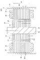
- FIG. 2 is a vertical cross-sectional view showing the motor 100.
- the axial length H1 of the rotor core 10 is longer than the axial length H2 of the stator core 50.
- the rotor core 10 protrudes from the stator core 50 on both sides in the axial direction.
- the length H1 of the rotor core 10 is 50 mm, and the length H2 of the stator core 50 is 45 mm.
- the length in the axial direction is also referred to as the height in the stacking direction.
- Balance weights for increasing inertia may be provided at both ends of the rotor core 10 in the axial direction.
- the rotor core 10 is a laminated body in which the first core sheet 101 is laminated in the axial direction.
- the first core sheet 101 is formed by pressing an electromagnetic steel sheet.
- the thickness T1 of the first core sheet 101 is 0.50 mm.
- the silicon content of the first core sheet 101 is 3.3%.
- the silicon content is the silicon (Si) content (wt%) in the first core sheet 101.
- the Vickers hardness Hv of the first core sheet 101 is 180.
- the iron loss density of the first core sheet 101 is 1.18 W / kg.
- the iron loss density is a measurement result when a magnetic flux density of 1.0 T is induced at a frequency of 50 Hz by a test based on JIS_C2550.
- the stator core 50 is a laminated body in which the second core sheet 501 is laminated in the axial direction.
- the second core sheet 501 is formed by pressing an electromagnetic steel sheet.
- the thickness T2 of the second core sheet 501 is 0.35 mm.
- the silicon content of the second core sheet 501 is 3.5%.
- the Vickers hardness Hv of the second core sheet 501 is 205.
- the iron loss density of the second core sheet 501 is 0.98 W / kg.
- the thickness T1 of the first core sheet 101 is thicker than the thickness T2 of the second core sheet 501.
- the silicon content of the first core sheet 101 is lower than the silicon content of the second core sheet 501.
- the Vickers hardness Hv of the first core sheet 101 is lower than the Vickers hardness Hv of the second core sheet 501.
- the iron loss density of the first core sheet 101 is higher than the iron loss density of the second core sheet 501.
- the first core sheet 101 has a characteristic that it is easy to press, that is, has good workability, as compared with the second core sheet 501.
- Such a first core sheet 101 and a second core sheet 501 can be obtained by changing the type and grade of the electromagnetic steel sheet. The effects of the differences in the characteristics of the core sheets 101 and 501 will be described later.
- the thickness, silicon content, Vickers hardness, and iron loss density of the core sheets 101 and 501 described above are merely examples.
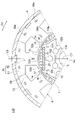
- FIG. 3 is an enlarged view showing a portion facing the rotor 1 and the stator 5.
- the permanent magnet 20 is inserted into each magnet insertion hole 11 of the rotor 1.
- the circumferential center of the magnet insertion hole 11 is the polar center.
- An interpole portion M is formed between the adjacent magnet insertion holes 11.
- the magnet insertion hole 11 extends linearly along a radial straight line passing through the pole center, that is, orthogonal to the magnetic pole center line C1. However, the magnet insertion hole 11 may extend in a V shape that is convex toward the axis Ax side.
- a plurality of slits 13 are formed on the radial outer side of each magnet insertion hole 11.
- Each of the slits 13 extends in the radial direction and has a width of, for example, 1 mm in the circumferential direction.
- the slit 13 is formed to bring the magnetic flux distribution of the permanent magnet 20 closer to a sine wave.
- the seven slits 13 are formed symmetrically with respect to the magnetic pole center line C1.
- the number and arrangement of the slits 13 are arbitrary.
- Through holes 102, 103 and slits 104 are formed inside the rotor core 10 in the radial direction of each magnet insertion hole 11.
- the through holes 102, 103 and the slit 104 are used as holes for inserting a refrigerant flow path or a jig through which the refrigerant passes.
- the through hole 102 is formed on the magnetic pole center line C1.
- the through hole 103 is formed on the inner side in the radial direction of the interpole portion M.
- the slit 104 is formed inside the through hole 102 in the radial direction and extends in an arc shape in the circumferential direction.
- the through holes 102, 103 and the slit 104 do not necessarily have to be provided.
- the caulking portion 105 for fixing the first core sheet 101 of the rotor core 10 is formed on the radial inside of the interpole portion M.
- the caulking portion 105 is not limited to this position, and may be formed at a position that does not block the magnetic path in the rotor core 10 as much as possible.
- the magnet insertion hole 11 has flux barriers 12 at both ends in the circumferential direction.
- the flux barrier 12 is a gap portion formed at both ends in the circumferential direction of the magnet insertion hole 11 and located outside the permanent magnet 20 in the circumferential direction.
- a bridge portion 14 is formed between the flux barrier 12 and the outer circumference 10a of the rotor core 10.
- the bridge portion 14 is a thin-walled portion extending in the circumferential direction along the outer peripheral portion 10a.
- the tooth 52 of the stator 5 has a tooth tip portion 52a facing the outer peripheral portion 10a of the rotor core 10.
- the width of the tooth tip portion 52a in the circumferential direction is wider than that of the other portion of the tooth 52.
- the radial straight line passing through the circumferential center of the teeth 52 is referred to as a teeth center line C5.
- the magnetic flux generated from the permanent magnet 20 is distributed in a sinusoidal shape that peaks on the magnetic pole center line C1. Therefore, as shown in FIG. 3, when the center of the permanent magnet 20 faces the tooth 52 of the stator 5, that is, when the magnetic pole center line C1 coincides with the tooth center line C5, the magnetic flux emitted from the permanent magnet 20 Flows most to the teeth 52 and interlinks with the coil 55.
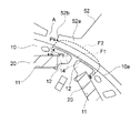
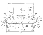
- FIG. 4 is a diagram showing a facing portion between the magnetic pole of the rotor 1 and the teeth 52. End faces 52b are formed at both ends of the tooth tip portion 52a of the teeth 52 in the circumferential direction. A slot opening A is formed between the end faces 52b of the adjacent teeth 52. The slot opening A is the entrance of the slot 53 facing the rotor 1.
- the magnet insertion holes 11 face the two slot openings A on both sides of the teeth 52.
- the two bridge portions 14 at both ends of the magnet insertion hole 11 face the tooth tips 52a of the teeth 52 on both sides of the teeth 52 with which the permanent magnet 20 faces.
- FIG. 5 is an enlarged view of the bridge portion 14 and its surroundings.
- the bridge portion 14 extends in the circumferential direction along the outer peripheral portion 10a of the rotor core 10.
- the radial width of the bridge portion 14 is here uniform in the extending direction of the bridge portion 14. However, the radial width of the bridge portion 14 may change.
- the minimum width in the radial direction of the bridge portion 14 is Hb.
- the length of the bridge portion 14 in the circumferential direction is defined as the length Wb.
- the minimum width Hb of the bridge portion 14 is set to a width capable of suppressing a short circuit of magnetic flux between adjacent permanent magnets 20.
- the minimum width Hb of the bridge portion 14 is set to be less than the thickness T1 of the first core sheet 101 (FIG. 2) (Hb ⁇ T1).
- the minimum width Hb of the bridge portion 14 is 0.30 mm.
- the length Wb of the bridge portion 14 is longer than the minimum width Hb.
- the minimum distance between the two bridge portions 14 at both ends of the magnet insertion hole 11 is Lb.
- the minimum distance Lb is the distance between the two end points Pb closest to each other in the two bridge portions 14 at both ends of the magnet insertion hole 11.
- the maximum distance between the two slot openings A facing the magnet insertion hole 11 is Ls.
- the maximum distance Ls is the distance between the two end points Ps on the inner peripheral side of the two slot openings A facing the magnet insertion hole 11 and on the side separated from each other.
- the minimum distance Lb of the two bridge portions 14 at both ends of the magnet insertion hole 11 is narrower than the maximum distance Ls of the two slot openings A facing the magnet insertion hole 11 (Lb ⁇ Ls).
- FIG. 6 is a diagram for explaining a short circuit of magnetic flux between adjacent permanent magnets 20.
- the magnetic flux between the adjacent permanent magnets 20 flows through the bridge portion 14, as indicated by the arrow F1.
- the method of forming the narrow bridge portion 14 having the minimum width Hb will be described later.
- the minimum distance Lb of the two bridge portions 14 at both ends of the magnet insertion hole 11 is made narrower than the maximum distance Ls of the two slot openings A facing the magnet insertion hole 11 (Lb ⁇ Ls).
- the first core sheet 101 constituting the rotor core 10 and the second core sheet 501 constituting the stator core 50 are formed by pressing separate electromagnetic steel sheets.
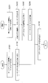
- FIG. 7A is a flowchart showing a press working process for forming the first core sheet 101.
- FIG. 8 is a plan view showing the electrical steel sheet 10S from which the first core sheet 101 is punched out.
- the electrical steel sheet 10S is a strip-shaped steel sheet long in one direction, and is also referred to as a first electrical steel sheet.
- the electrical steel sheet 10S has a thickness of 0.50 mm, a silicon content of 3.3%, a Vickers hardness Hv of 180, and an iron loss density of 1.18 W / kg.
- the electromagnetic steel sheet 10S is conveyed in the longitudinal direction (step S11), and the first core sheet 101 is formed by dividing it into a plurality of stages and punching it with a press die (step S12).
- the electrical steel sheet 10S is punched into the shapes of the center hole 15, the through holes 102, 103, the slit 104, the slit 13, the magnet insertion hole 11 (including the flux barrier 12), and the outer circumference 10a.
- the die clearance of the press die at this time is 5% of the thickness T1 of the electromagnetic steel sheet 10S, specifically 0.025 mm. This will be described later with reference to FIGS. 12A and 12B.
- FIG. 7B is a flowchart showing a press working process for forming the second core sheet 501.
- FIG. 9 is a plan view showing an electromagnetic steel sheet 50S from which the second core sheet 501 is punched.
- the electrical steel sheet 50S is a strip-shaped steel sheet long in one direction, and is also referred to as a second electrical steel sheet.
- the electrical steel sheet 50S has a thickness of 0.35 mm, a silicon content of 3.5%, a Vickers hardness Hv of 205, and an iron loss density of 0.98 W / kg.
- the electromagnetic steel sheet 50S is conveyed in the longitudinal direction (step S21) and punched out with a press die to form the second core sheet 501 (step S22).
- the electromagnetic steel sheet 50S is punched into a shape in which the split core 50A is linearly developed.
- the die clearance of the press die at this time is 8% of the thickness T2 of the electromagnetic steel sheet 50S, specifically 0.028 mm.
- FIG. 10 is a flowchart showing the assembly process of the electric motor 100.
- the first core sheets 101 obtained in the step of FIG. 7A are laminated in the axial direction to form the rotor core 10 (step S101).
- the permanent magnet 20 is embedded in the rotor core 10. That is, the permanent magnet 20 is inserted into the magnet insertion hole 11 of the rotor core 10 (step S102). Further, if necessary, the balance weight is fixed to the rotor core 10. As a result, the rotor 1 is completed.
- the second core sheet 501 obtained in the step of FIG. 7B is laminated in the axial direction to form the split core 50A (step S201).
- the split cores 50A are connected in an annular shape and joined by welding or the like to form the stator core 50 (step S202).
- the insulating portion is attached to the stator core 50 (step S203), and the coil 55 is wound around the stator core 50 (step S204). This completes the stator 5.
- the rotor 1 is incorporated inside the stator 5 thus formed (step S110). This completes the motor 100.
- the coil 55 is wound after forming the annular stator core 50, but the coil 55 may be wound in the state of the split core 50A, and then the split core 50A may be combined in a ring shape.
- the stator core 50 is not necessarily limited to the one in which the split cores 50A are connected, and may have an annular integrated configuration.
- the inner portion (indicated by reference numeral D) of the second core sheet 501 of the electrical steel sheet 50S is used. It is useless. That is, the electromagnetic steel sheet 50S cannot be effectively used.
- the waste of the magnetic steel sheet 50S is reduced by punching the split core 50A into a linearly arranged shape, for example. can do. That is, the material of the electrical steel sheet 50S can be effectively used.
- FIG. 12A is a schematic view showing how the electromagnetic steel sheet 10S is punched to form the first core sheet 101.
- the first core sheet 101 is shown as a disk shape.
- FIG. 12B is a schematic view showing the press die 8.
- the first core sheet 101 is punched out by shearing by pressing the electromagnetic steel sheet 10S in the thickness direction thereof.
- the press die 8 has a die 81 that supports the electrical steel sheet 10S from below, and a punch 82 that applies pressure P to the electrical steel sheet 10S from above.
- the inner dimension of the die 81 is Dd, and the outer dimension of the punch 82 is Dp.
- a shear force is applied to the electrical steel sheet 10S between the tooth surface 81a of the die 81 and the tooth surface 82a of the punch 82.
- a clearance is set between the tooth surface 81a of the die 81 and the tooth surface 82a of the punch 82. This clearance is referred to as mold clearance C.
- the die clearance C of the press die 8 is set to 5% of the thickness T1 of the electrical steel sheet 10S.
- the die clearance C when punching a portion other than the bridge portion 14 does not necessarily have to be 5% of the thickness T1, and may be, for example, 8% of the thickness T1.
- the mold clearance C between the die 81 and the punch 82 is set to 8% of the thickness of the electrical steel sheet 50S.
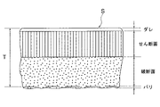
- FIG. 13 is a diagram showing a state of a machined surface of a general electrical steel sheet (referred to as electrical steel sheet S).
- the cut surface of the electrical steel sheet S by punching (indicated by reference numeral E in FIG. 12A) is referred to as a machined surface. Dripping, shearing surfaces, fracture surfaces, and burrs are formed on the machined surface in the shearing direction.
- the sagging is a curved surface in which the surface of the electrical steel sheet S is pushed down by the punch 82 and deformed.
- the shear surface is a flat surface generated by being rubbed by the punch 82, and scratches are formed in the shear direction.
- the fracture surface is a surface that is cracked and broken, and is a surface that is rougher than the sheared surface.
- the burrs are protrusions formed by pushing down the electromagnetic steel sheet S against the punch 82.
- the die clearance C is small, but if the die clearance C is small, wear of the press die 8, that is, die wear may occur. .. As the mold wear progresses, it develops into abnormal wear called mold galling.
- FIG. 14A is a diagram showing a state immediately before forming the bridge portion 14 by punching the electromagnetic steel sheet 10S.
- a magnet insertion hole 11 including a flux barrier 12 is formed.
- FIG. 14B is a diagram showing a state in which the bridge portion 14 is formed by punching the electromagnetic steel sheet 10S.
- the outer circumference 10a of the rotor core 10 is formed by punching the electromagnetic steel sheet 10S.
- a bridge portion 14 is formed between the outer circumference 10a and the flux barrier 12.
- FIG. 15A is a diagram showing a process of forming the bridge portion 14 shown in FIG. 14B.
- the electromagnetic steel sheet 10S is cut at the outer circumference 10a of the rotor core 10.
- the die clearance C in the press die 8 forming the bridge portion 14 is 5% of the thickness T1 of the electrical steel sheet 10S.
- the bending of the electromagnetic steel sheet 10S pressed by the punch 82 may cause deformation such as tilting (warping) of the bridge portion 14. There is sex. The narrower the width of the bridge portion 14, the more easily deformation occurs.
- the width of the bridge portion 14 is the narrowest, and therefore high processing accuracy is required.
- the magnet insertion hole 11, the slit 13, the center hole 15, and the like of the rotor core 10 are not required to have high processing accuracy like the bridge portion 14.
- the die clearance C in the press die 8 is set to 5% of the thickness T1 of the electromagnetic steel sheet 10S. It is not necessary and may be set to 8%, for example.
- FIG. 16 is a vertical cross-sectional view showing the motor 100D of the comparative example.
- the first core sheet 101 constituting the rotor core 10 and the second core sheet 501 constituting the stator core 50 are made of the same electrical steel sheet.
- the thickness T of the electrical steel sheet is 3.5 mm
- the silicon content is 3.5%
- the Vickers hardness Hv is 205
- the iron loss density is 0.98 W / kg.
- the axial length H1 of the rotor core 10 is 50 mm, and the axial length H2 of the stator core 50 is 45 mm.
- FIG. 17 is an enlarged view showing the facing portion between the rotor 1 and the stator 5 in the comparative example.
- the rotor 1 of the comparative example is configured in the same manner as the rotor 1 of the first embodiment except for the bridge portion 14.
- the stator 5 of the comparative example is configured in the same manner as the stator 5 of the first embodiment.
- FIG. 18 is a diagram showing a facing portion between the magnetic pole of the rotor 1 and the teeth 52.
- the minimum distance between the two bridge portions 14 at both ends of the magnet insertion hole 11 is Lb.
- This minimum distance Lb is the distance between the end points Pb closest to each other at the two bridge portions 14 at both ends of the magnet insertion hole 11.
- the maximum distance between the two slot openings A facing the magnet insertion hole 11 is Ls.
- the maximum distance Ls is the distance between the two end points Ps on the inner peripheral side of the two slot openings A facing the magnet insertion hole 11 and on the side separated from each other.
- the minimum distance Lb of the two bridge portions 14 at both ends of the magnet insertion hole 11 is wider than the maximum distance Ls of the two slot openings A facing the magnet insertion hole 11 (Lb> Ls).
- FIG. 19 is an enlarged view of the bridge portion 14 and its surroundings. Since the thickness T of the first core sheet 101 is 0.35 mm, the minimum width Hb of the bridge portion 14 is set to 0.40 mm so that the bridge portion 14 is not deformed during press working.
- FIG. 20 is a diagram for explaining a short circuit of magnetic flux between adjacent permanent magnets 20.
- the minimum width Hb of the bridge portion 14 of the comparative example is 0.40 mm, which is wider than the minimum width Hb (0.30 mm) of the bridge portion 14 of the first embodiment. Therefore, as compared with the first embodiment, the magnetic flux flowing through the bridge portion 14 increases as shown by the arrow F1. That is, the short-circuit magnetic flux between the adjacent permanent magnets 20 increases.
- the minimum distance Lb of the two bridge portions 14 at both ends of the magnet insertion hole 11 is wider than the maximum distance Ls of the two slot openings A facing the magnet insertion hole 11 (Lb> Ls). Therefore, as shown in FIG. 20, with the center of the permanent magnet 20 facing the teeth 52, the end point Ps of the tooth tip portion 52a of the teeth 52 is located closer to the polar center side than the end point Pb of the bridge portion 14. do.
- the magnetic flux tends to flow in the radial direction between the permanent magnet 20 and the tooth tip portion 52a. That is, a short circuit of the magnetic flux between the permanent magnets 20 via the tooth tip portion 52a is likely to occur.
- the first core sheet 101 and the second core sheet 501 are formed by punching the same electrical steel sheet.
- FIG. 21 is a flowchart showing a process of punching out an electromagnetic steel sheet 100S to form a first core sheet 101 and a second core sheet 501.
- FIG. 22 is a plan view showing the electrical steel sheet 100S from which the core sheets 101 and 501 are punched out.
- the electrical steel sheet 100S has a thickness of 0.35 mm, a silicon content of 3.5%, a Vickers hardness Hv of 205, and an iron loss density of 0.98 W / kg.
- the electromagnetic steel sheet 100S is a strip-shaped steel sheet that is long in one direction.
- the electrical steel sheet 100S is conveyed in the longitudinal direction (step S301), and the electrical steel sheet 100S is punched into the shape of the rotor core 10 by a press die to form the first core sheet 101 (step S302).
- the mold clearance at this time is 8% of the thickness of the electrical steel sheet 100S.
- the electromagnetic steel sheet 100S is punched into the shape of the stator core 50 to form the second core sheet 501 (step S303).
- the mold clearance at this time is also 8% of the thickness of the electrical steel sheet 100S.
- first core sheet 101 and the second core sheet 501 are formed of the same electromagnetic steel sheet 100S, as shown in FIG. 22, after the electromagnetic steel sheet 100S is punched out to form the first core sheet 101, An annular second core sheet 501 can be formed by punching the periphery thereof, and the material yield is good.
- the rotor 1 and the stator 5 are assembled as described with reference to FIG. 10, and the electric motor 100 is manufactured.
- the minimum width Hb of the bridge portion 14 is thin. However, if the minimum width Hb of the bridge portion 14 is narrowed, the bridge portion 14 may be deformed during press working. Therefore, the minimum width Hb of the bridge portion 14 is generally set to be equal to or larger than the thickness of the electrical steel sheet, for example, 0.40 mm.
- the mold clearance C is reduced, mold wear or mold galling may occur. Mold wear and mold galling are more likely to occur as the mold clearance C is smaller, and are more likely to occur as the hardness of the electrical steel sheet is higher. Therefore, the mold clearance C is generally set to 5 to 15% of the thickness of the electrical steel sheet.
- the iron loss generated in the cores such as the rotor core 10 and the stator core 50 includes a hysteresis loss and a vortex current loss.
- Hysteresis loss is the loss that occurs when the magnetic domain of the core changes direction of the magnetic field due to an alternating magnetic field.
- the hysteresis loss Ph is expressed by the following Steinmetz empirical formula (1).
- P h k h fB m 1.6 ... (1)
- kh is a proportionality constant
- f is a frequency
- B m is the maximum magnetic flux density.
- Eddy current loss is caused by eddy currents generated inside the core.
- the eddy current loss Pe is expressed by the following equation (2).
- P e ke ( tfB m ) 2 / ⁇ ... (2)
- ke is a proportionality constant
- t is the thickness of the electrical steel sheet
- f is the frequency
- B m the maximum magnetic flux density
- ⁇ is the electrical resistivity of the electrical steel sheet.
- the eddy current loss is smaller as the electrical resistivity ⁇ of the electromagnetic steel sheet is higher, it can be reduced by increasing the electrical resistivity ⁇ by using an electromagnetic steel sheet in which silicon (Si) is added to iron (Fe).
- Si silicon
- Fe iron
- the hardness of the electrical steel sheet increases and becomes brittle as the silicon content increases. If the hardness of the electrical steel sheet is too high, the electrical steel sheet is easily cracked and press working becomes difficult.
- the rotor core 10 and the stator core 50 are made of an electromagnetic steel sheet containing 3 to 4% of silicon. If the silicon content exceeds 4%, press working is difficult, so the upper limit of the silicon content is 4%.
- the eddy current loss is proportional to the square of the thickness T of the electrical steel sheet. Therefore, the thinner the thickness T of the electrical steel sheet, the smaller the eddy current loss and the smaller the iron loss density.
- the rotor core 10 and the stator core 50 are made of an electromagnetic steel sheet having a thickness of 0.2 to 1.0 mm. If the thickness of the electrical steel sheet is less than 0.2 mm, rolling processing becomes difficult and the manufacturing cost of the electrical steel sheet increases. Therefore, the lower limit of the thickness of the electrical steel sheet is 0.2 mm.
- the thinner the magnetic steel sheet the smaller the volume of the bridge portion 14 of the rotor core 10.
- the bridge portion 14 is likely to be deformed during press working.
- the deformation of the bridge portion 14 is the collapse of the bridge portion 14 shown in FIG. 15 (B).
- the bridge portion 14 is likely to break due to the centrifugal force during rotation of the rotor 1.
- the first core sheet 101 of the rotor core 10 and the second core sheet 501 of the stator core 50 are formed by punching the same electrical steel sheet as described in Comparative Example (FIG. 22).
- an electromagnetic steel sheet having a thickness of 0.35 mm and a silicon content of 3.5% is often used.
- the die clearance C of the press die is set to 8% of the thickness of the electrical steel sheet.
- the first core sheet 101 of the rotor core 10 and the second core sheet 501 of the stator core 50 are formed of different electrical steel sheets.
- the thickness of the second core sheet 501 is 0.35 mm, the silicon content is 3.5%, and the Vickers hardness Hv is 205, whereas the thickness of the first core sheet 101 is 0.50 mm and the silicon content is 3.3%, Vickers hardness Hv is 180.
- the die clearance C when the electromagnetic steel sheet 10S is punched out to form the first core sheet 101 and the die clearance C when the electromagnetic steel sheet 50S is punched out to form the second core sheet 501. Is different.
- the mold clearance C when the electromagnetic steel sheet 10S is punched to form the first core sheet 101 is set to 5% of the thickness T1 of the first core sheet 101.
- the die clearance C when the electromagnetic steel sheet 50S is punched to form the second core sheet 501 is set to 8% of the thickness T2 of the second core sheet 501.
- the hardness of the first core sheet 101 is lowered, so that mold wear and mold galling are less likely to occur even if the mold clearance C is small. Therefore, even if the ratio of the mold clearance C to the thickness T1 of the first core sheet 101 is reduced to, for example, 5%, mold wear and mold galling are unlikely to occur.
- the volume of the bridge portion 14 becomes large, and the bridge portion 14 is less likely to be deformed during press working.
- the minimum width Hb of the bridge portion 14 can be reduced to 0.30 mm, which is less than the thickness T1 of the first core sheet 101.
- the minimum width Hb of the bridge portion 14 can be narrowed by press working in this way, it is possible to suppress a short circuit of the magnetic flux between the permanent magnets 20. That is, it is possible to suppress a short circuit of the magnetic flux between the permanent magnets 20 via the bridge portion 14 while suppressing an increase in manufacturing cost.
- the thickness of the first core sheet 101 of the first embodiment is, for example, 0.50 mm, which is thicker than 0.35 mm of the comparative example.
- the silicon content of the first core sheet 101 of the first embodiment is, for example, 3.3%, which is lower than 3.5% of the comparative example. Therefore, the iron loss density of the first core sheet 101 of the first embodiment is larger than the iron loss density of the first core sheet 101 of the comparative example.
- the iron loss density of the first core sheet 101 is 0.98 W / kg in the comparative example, whereas it is an embodiment. In 1, it is 1.18 W / kg.
- the iron loss density of the second core sheet 501 is 0.98 W / kg in both Comparative Example and Embodiment 1.
- the iron loss that occurs while driving the motor 100 occurs more in the stator core 50 than in the rotor core 10.
- the ratio of the iron loss generated in the rotor core 10 to the iron loss generated in the stator core 50 is 2: 8.
- the reason is as follows. That is, since the permanent magnet 20 is fixed to the rotor core 10 and a constant magnetic flux is always generated from the permanent magnet 20, the change in the magnetic flux in the rotor core 10 with the rotation of the rotor 1 is small. On the other hand, in the stator core 50, the magnetic flux flowing in from the rotor 1 changes depending on the rotation position of the rotor 1, so that the change in the magnetic flux is large. Therefore, the iron loss generated in the rotor core 10 is smaller than the iron loss generated in the stator core 50.
- the iron loss density of the first core sheet 101 is 0.98 W / kg in the comparative example, and 1.18 W / kg in the first embodiment.
- the iron loss generated in the stator core 50 which accounts for 80% of the total iron loss, is the same in the comparative example and the first embodiment.
- the minute is 4%.
- the minimum distance Lb between the two bridge portions 14 at both ends of the magnet insertion hole 11 and the maximum distance between the two slot openings A facing the magnet insertion hole 11 Ls satisfies Lb ⁇ Ls.
- the end point Pb of the bridge portion 14 is located on the pole center side of the end point Ps of the tooth tip portion 52a in a state where the center of the permanent magnet 20 faces the teeth 52. Therefore, the magnetic flux between the permanent magnet 20 and the tooth tip portion 52a wraps around to the pole center side (see FIG. 6), and a short circuit of the magnetic flux via the tooth tip portion 52a is less likely to occur.
- the short circuit of the magnetic flux between the permanent magnets 20 can be effectively suppressed. can.
- the amount of magnetic flux interlinking with the coil 55 of the stator 5 increases.
- the comparison that the minimum width Hb of the bridge portion 14 is 0.40 mm and satisfies Lb> Ls.
- the magnet torque of the rotor 1 is determined by the product of the magnetic flux interlinking the coil 55 of the stator 5 and the current flowing through the coil 55. Therefore, by increasing the amount of magnetic flux interlinking with the coil 55, the current for generating the whirlpool net torque can be reduced, and thereby the copper loss generated in the coil 55 can be reduced.
- the rotor core 10 uses the first core sheet 101 having a higher iron loss density than the second core sheet 501 of the stator core 50, and the minimum width Hb of the bridge portion 14 is set to be less than the thickness T1 of the first core sheet 101.
- iron loss increases, but copper loss can be reduced.
- the copper loss of the rotor core 10 is reduced by 8% as compared with the comparative example, while the increase of the iron loss of the motor 100 is 4%. That is, the decrease in copper loss is larger than the increase in iron loss. This makes it possible to improve the motor efficiency.
- the thicker the electrical steel sheet and the larger the iron loss density the lower the price per unit weight.
- the thickness of the first core sheet 101 of the rotor core 10 is thick and the iron loss density is large, an inexpensive electromagnetic steel sheet can be used, and the manufacturing cost of the motor 100 can be reduced.
- the thickness T1 of the first core sheet 101 is thicker than that of the comparative example, but the length H1 of the rotor core 10 is the same as that of the comparative example.
- the number of sheets is smaller than that of the comparative example. As the number of laminated first core sheets 101 is smaller, the number of times the electromagnetic steel sheet 10S is punched out is smaller, so that the manufacturing cost can be reduced.
- the axial length of the bridge portion 14 per one of the first core sheets 101 becomes longer. Therefore, even if the minimum width Hb of the bridge portion 14 is narrowed, the volume of the bridge portion 14 per one of the first core sheets 101 becomes large. As a result, it is possible to suppress breakage of the bridge portion 14 due to centrifugal force during rotation of the rotor 1.
- the size of the permanent magnet 20 can be reduced by the increase of the amount of magnetic flux.
- the amount of magnetic flux interlinking with the coil 55 of the stator 5 is increased by 4% as compared with the comparative example, the same torque as in the comparative example can be generated even if the axial length of the permanent magnet 20 is reduced by 4%.
- the electric motor 100 can be miniaturized and the manufacturing cost can be reduced.
- the permanent magnet 20 arranged in the protruding portion of the rotor core 10 does not face the stator core 50. Therefore, the magnetic flux from the permanent magnet 20 arranged in the protruding portion of the rotor core 10 tends to flow to the adjacent permanent magnet 20.
- the above configuration for suppressing a short circuit of the magnetic flux via the bridge portion 14 is particularly useful for the motor motor 100 in which the rotor core 10 protrudes in the axial direction from the stator core 50.
- the electromagnetic steel sheet 10S is punched to form the magnet insertion hole 11 as shown in FIG. 14 (A), and then the electromagnetic steel sheet 10S is punched to form the rotor core as shown in FIG. 14 (B).
- the outer circumference 10a of 10 is formed.
- the deformation of the bridge portion 14 can be suppressed by suppressing the bridge portion 14 with the plate retainer 83 as shown in FIG. 15 (A). That is, the formation of the narrow bridge portion 14 having the minimum width Hb becomes easy.
- the first core sheet 101 and the second core sheet 501 are formed of a common electromagnetic steel sheet 100S. Therefore, the plate presser 83 that presses the bridge portion 14 must be arranged in consideration of the position of the press die that punches the electromagnetic steel sheet 100S into the shape of the stator core 50, and it is difficult to arrange the plate presser 83.
- first core sheet 101 and the second core sheet 501 are formed of separate electrical steel sheets 10S and 50S, it is easy to arrange the plate retainer 83 that presses the bridge portion 14.
- the thickness T1 of the first core sheet 101 of the rotor core 10 is thicker than the thickness T2 of the second core sheet 501 of the stator core 50.
- the iron loss density of the first core sheet 101 is higher than the iron loss density of the second core sheet 501.
- the silicon content of the first core sheet 101 is lower than the silicon content of the second core sheet 501.
- the hardness of the first core sheet 101 is lower than the hardness of the second core sheet 501.
- the rotor core 10 is composed of the first core sheet 101
- the stator core 50 is composed of the second core sheet 501
- the thickness T1 of the first core sheet 101 is the first.
- the thickness of the 2-core sheet 501 is thicker than T2.
- a bridge portion 14 is formed between the outer peripheral portion 10a of the rotor core 10 and the magnet insertion hole 11, and the minimum radial width Hb of the bridge portion 14 is less than the thickness T1 of the first core sheet 101.
- the minimum width Hb of the bridge portion 14 is less than the thickness T1 of the first core sheet 101, it is possible to suppress a short circuit of the magnetic flux between the adjacent permanent magnets 20. Further, since the thickness T1 of the first core sheet 101 is thicker than the thickness T2 of the second core sheet 501, the volume of the bridge portion 14 per one of the first core sheets 101 becomes large. As a result, even if the minimum width Hb of the bridge portion 14 is narrowed, the deformation of the bridge portion 14 during press working can be suppressed. Further, it is possible to suppress the breakage of the bridge portion 14 due to the centrifugal force during the rotation of the rotor 1.
- the iron loss density of the first core sheet 101 is higher than the iron loss density of the second core sheet 501. This is because the thickness T1 of the first core sheet 101 is thicker than the thickness T2 of the second core sheet 501, and the silicon content of the first core sheet 101 is lower than the silicon content of the second core sheet 501. It depends. Therefore, it is possible to suppress the deformation of the bridge portion 14 during press working and to reduce the mold clearance C without causing mold wear and mold galling. As a result, a thin bridge portion 14 having a minimum width Hb can be formed by press working, and a short circuit of magnetic flux between the permanent magnets 20 can be suppressed.
- the silicon content of the first core sheet 101 is lower than the silicon content of the second core sheet 501, the hardness of the first core sheet 101 is higher than the hardness of the second core sheet 501. Therefore, the mold clearance C can be reduced without causing mold wear and mold galling during press working of the first core sheet 101. As a result, a thin bridge portion 14 having a minimum width Hb can be formed by press working, and a short circuit of magnetic flux between the permanent magnets 20 can be suppressed.
- the mold clearance C is provided without causing mold wear and mold galling during press working of the first core sheet 101. It can be made smaller. As a result, it becomes possible to form a narrow bridge portion 14 having a minimum width Hb by press working and suppress a short circuit of magnetic flux between the permanent magnets 20.
- the minimum distance Lb of the two bridge portions 14 at both ends of the magnet insertion hole 11 and the maximum distance Ls of the distance between the two slot openings A facing the magnet insertion hole 11 satisfy Lb ⁇ Ls, they are permanent. With the center of the magnet 20 facing the teeth 52, it is possible to suppress a short circuit of the magnetic flux between the permanent magnets 20 via the tooth tip portion 52a of the teeth 52.
- the minimum width Hb of the bridge portion 14 is less than the thickness T2 of the second core sheet 501, it is difficult for the magnetic flux to flow through the bridge portion 14, and therefore it is possible to suppress a short circuit of the magnetic flux between the adjacent permanent magnets 20. can.
- the stator core 50 is a combination of a plurality of divided cores 50A in the circumferential direction
- the electromagnetic steel sheet 50S can be punched into a shape in which the divided cores 50A are arranged in a straight line. Therefore, the electromagnetic steel sheet 50S can be effectively used, and the manufacturing cost of the electric motor 100 can be reduced.
- the thickness of the first core sheet 101 is thicker than 0.35 mm and the thickness of the second core sheet 501 is 0.35 mm or less, deformation of the bridge portion 14 during press working is suppressed and the stator core is suppressed.
- the increase in iron loss at 50 can be suppressed.
- the silicon content of the first core sheet 101 is less than 3.5% and the silicon content of the second core sheet 501 is 3.5% or more, the gold at the time of press working of the first core sheet 101 is obtained. It is possible to suppress mold wear and mold galling, and to suppress an increase in iron loss in the stator core 50.
- the Vickers hardness of the first core sheet 101 is lower than 200 and the Vickers hardness of the core sheet 500 is 200 or more, the mold wear and galling during press working on the first core sheet 101 are suppressed, and the mold galling is suppressed.
- the rigidity of the stator core 50 can be increased.
- FIG. 23 is a vertical sectional view showing the electric motor 100A of the second embodiment.
- the stator core 50 of the stator 5 is annealed to improve the magnetic characteristics.
- the electric motor 100A of the second embodiment is configured in the same manner as the electric motor 100 of the first embodiment except that the stator core 50 is annealed.
- the machined surface is distorted by the shearing force and remains as residual strain. Residual strain can change the magnetic properties of the second core sheet 501.
- the second core sheet 501 punched from the electromagnetic steel sheet 50S is annealed to eliminate the residual strain caused by the punching and improve the magnetic characteristics of the second core sheet 501.
- iron loss in the stator core 50 can be reduced and motor efficiency can be improved.
- stator core 50 As compared with the stator core 50, the change in magnetic flux is small and the iron loss is small in the rotor core 10. Further, when the residual strain remains in the bridge portion 14 of the rotor core 10, the effect of suppressing the short circuit of the magnetic flux between the permanent magnets 20 becomes large, which is desirable. Therefore, it is desirable that the stator core 50 is annealed and the rotor core 10 is not annealed.
- the iron loss in the stator core 50 can be reduced and the motor efficiency can be improved.
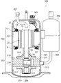
- FIG. 24 is a vertical sectional view showing a compressor 300 to which the electric motor of each embodiment is applicable.
- the compressor 300 is a rotary compressor and is used, for example, in the refrigeration cycle device 400 (FIG. 25).
- the compressor 300 includes a compression mechanism unit 310, an electric motor 100 for driving the compression mechanism unit 310, a shaft 25 for connecting the compression mechanism unit 310 and the electric motor 100, and a closed container 301 for accommodating these.
- the closed container 301 is a container made of a steel plate, and has a cylindrical shell and an upper part of the container that covers the upper part of the shell.
- the stator 5 of the electric motor 100 is incorporated inside the shell of the closed container 301 by shrink fitting, press fitting, welding, or the like.
- a discharge pipe 307 for discharging the refrigerant to the outside and a terminal 305 for supplying electric power to the motor 100 are provided. Further, an accumulator 302 for storing the refrigerant gas is attached to the outside of the closed container 301. Refrigerating machine oil that lubricates the bearing portion of the compression mechanism portion 310 is stored in the bottom of the closed container 301.
- the compression mechanism unit 310 includes a cylinder 311 having a cylinder chamber 312, a rolling piston 314 fixed to the shaft 25, a vane that divides the inside of the cylinder chamber 312 into a suction side and a compression side, and both ends in the axial direction of the cylinder chamber 312. It has an upper frame 316 and a lower frame 317 that close the frame.
- Both the upper frame 316 and the lower frame 317 have a bearing portion that rotatably supports the shaft 25.
- An upper discharge muffler 318 and a lower discharge muffler 319 are attached to the upper frame 316 and the lower frame 317, respectively.
- the cylinder 311 is provided with a cylindrical cylinder chamber 312 centered on the axis Ax.
- An eccentric shaft portion 25a of the shaft 25 is located inside the cylinder chamber 312.
- the eccentric shaft portion 25a has a center eccentric with respect to the axis Ax.
- a rolling piston 314 is fitted on the outer periphery of the eccentric shaft portion 25a. When the electric motor 100 rotates, the eccentric shaft portion 25a and the rolling piston 314 rotate eccentrically in the cylinder chamber 312.
- the cylinder 311 is formed with a suction port 313 for sucking the refrigerant gas in the cylinder chamber 312.
- a suction pipe 303 communicating with the suction port 313 is attached to the closed container 301, and the refrigerant gas is supplied from the accumulator 302 to the cylinder chamber 312 via the suction pipe 303.
- a low-pressure refrigerant gas and a liquid refrigerant are mixedly supplied to the compressor 300 from the refrigerant circuit of the refrigeration cycle device 400 (FIG. 25), but when the liquid refrigerant flows into the compression mechanism unit 310 and is compressed. , It causes a failure of the compression mechanism unit 310. Therefore, the accumulator 302 separates the liquid refrigerant and the refrigerant gas, and supplies only the refrigerant gas to the compression mechanism unit 310.
- refrigerant for example, R410A, R407C, R22, etc. may be used, but from the viewpoint of preventing global warming, it is desirable to use a refrigerant having a low GWP (global warming potential).
- GWP global warming potential
- the refrigerant having a low GWP for example, the following refrigerants can be used.
- the GWP of HFO-1234yf is 4.
- a hydrocarbon having a carbon double bond in the composition for example, R1270 (propylene) may be used.
- the GWP of R1270 is 3, which is lower than HFO-1234yf, but more flammable than HFO-1234yf.
- a mixture containing at least one of a halogenated hydrocarbon having a carbon double bond in the composition or a hydrocarbon having a carbon double bond in the composition for example, a mixture of HFO-1234yf and R32.
- the operation of the compressor 300 is as follows.
- the refrigerant gas supplied from the accumulator 302 is supplied into the cylinder chamber 312 of the cylinder 311 through the suction pipe 303.
- the shaft 25 rotates together with the rotor 1.
- the rolling piston 314 fitted to the shaft 25 rotates eccentrically in the cylinder chamber 312, and the refrigerant is compressed in the cylinder chamber 312.
- the compressed refrigerant passes through the discharge mufflers 318 and 319, further passes through the through holes 102 and 103 of the motor 100 (FIG. 1), rises in the closed container 301, and is discharged from the discharge pipe 307.
- the electric motor of each embodiment has high motor efficiency by suppressing a short circuit of magnetic flux between the permanent magnets 20. Therefore, the operating efficiency of the compressor 300 can be improved.
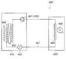
- FIG. 25 is a diagram showing the configuration of the refrigeration cycle device 400.
- the refrigerating cycle device 400 is, but is not limited to, an air conditioner here, and may be, for example, a refrigerator.
- the refrigeration cycle device 400 includes a compressor 401, a condenser 402, a decompression device 403, and an evaporator 404.
- the compressor 401, the condenser 402, the decompression device 403 and the evaporator 404 are connected by a refrigerant pipe 407 to form a refrigeration cycle. That is, the refrigerant circulates in the order of the compressor 401, the condenser 402, the decompression device 403, and the evaporator 404.
- the compressor 401, the condenser 402 and the decompression device 403 are provided in the outdoor unit 410.
- the compressor 401 is composed of the compressor 300 described with reference to FIG. 24.
- the outdoor unit 410 is provided with an outdoor blower 405.
- the evaporator 404 is provided in the indoor unit 420.
- the indoor unit 420 is provided with an indoor blower 406.
- the operation of the refrigeration cycle device 400 is as follows.
- the compressor 401 compresses and sends out the sucked refrigerant.
- the condenser 402 exchanges heat between the refrigerant sent out from the compressor 401 and the outdoor air, condenses the refrigerant, and sends it out as a liquid refrigerant.
- the decompression device 403 expands the liquid refrigerant sent out from the condenser 402 and sends it out as a low-temperature low-pressure liquid refrigerant.
- the evaporator 404 exchanges heat between the low-temperature low-pressure liquid refrigerant sent from the decompression device 403 and the indoor air, evaporates the refrigerant, and sends it out as a refrigerant gas.
- the air whose heat has been taken away by the evaporator 404 is supplied to the room by the indoor blower 406.
- the refrigerating cycle device 400 includes the compressor 300 having high operating efficiency, so that the operating efficiency of the refrigerating cycle device 400 can be improved.
Landscapes
- Engineering & Computer Science (AREA)
- Power Engineering (AREA)
- Manufacturing & Machinery (AREA)
- Physics & Mathematics (AREA)
- Mechanical Engineering (AREA)
- Thermal Sciences (AREA)
- General Engineering & Computer Science (AREA)
- Iron Core Of Rotating Electric Machines (AREA)
- Manufacture Of Motors, Generators (AREA)
- Permanent Field Magnets Of Synchronous Machinery (AREA)
- Compressor (AREA)
Abstract
Description
<電動機の構成>
図1は、実施の形態1の電動機100を示す横断面図である。図1に示す電動機100は、永久磁石埋込型電動機であり、例えば圧縮機300(図24)に用いられる。また、電動機100は、インバータによって駆動される。
次に、実施の形態1の電動機100の製造方法について説明する。ロータコア10を構成する第1コアシート101と、ステータコア50を構成する第2コアシート501とは、別々の電磁鋼板のプレス加工により形成される。
次に、実施の形態1に対する比較例について説明する。図16は、比較例の電動機100Dを示す縦断面図である。
次に、実施の形態1の作用について、比較例と対比して説明する。ロータ1では、ロータコア10の外周10aと磁石挿入孔11との間のブリッジ部14を介して、隣接する永久磁石20間の磁束の短絡が生じる可能性がある。
Ph=khfBm 1.6…(1)
ここで、khは比例定数、fは周波数、Bmは最大磁束密度である。
Pe=ke(tfBm)2/ρ…(2)
ここで、keは比例定数、tは電磁鋼板の厚さ、fは周波数、Bmは最大磁束密度、ρは電磁鋼板の電気抵抗率である。
(1)ロータコア10の第1コアシート101の厚さT1が、ステータコア50の第2コアシート501の厚さT2よりも厚い。
(2)第1コアシート101の鉄損密度が、第2コアシート501の鉄損密度よりも高い。
(3)第1コアシート101のケイ素含有量が、第2コアシート501のケイ素含有量よりも少ない。
(4)第1コアシート101の硬度が、第2コアシート501の硬度よりも低い。
以上説明したように、実施の形態1の電動機100では、ロータコア10が第1コアシート101で構成され、ステータコア50が第2コアシート501で構成され、第1コアシート101の厚さT1が第2コアシート501の厚さT2よりも厚い。ロータコア10の外周10aと磁石挿入孔11との間にブリッジ部14が形成され、ブリッジ部14の径方向の最小幅Hbが、第1コアシート101の厚さT1未満である。
図23は、実施の形態2の電動機100Aを示す縦断面図である。実施の形態2では、ステータ5のステータコア50に焼鈍処理が施して、磁気特性を向上させている。実施の形態2の電動機100Aは、ステータコア50に焼鈍処理が施されている点を除き、実施の形態1の電動機100と同様に構成されている。
図24は、各実施の形態の電動機が適用可能な圧縮機300を示す縦断面図である。圧縮機300は、ロータリ圧縮機であり、例えば冷凍サイクル装置400(図25)に用いられる。
(2)また、組成中に炭素の二重結合を有する炭化水素、例えばR1270(プロピレン)を用いてもよい。R1270のGWPは3であり、HFO-1234yfより低いが、可燃性はHFO-1234yfより高い。
(3)また、組成中に炭素の二重結合を有するハロゲン化炭化水素または組成中に炭素の二重結合を有する炭化水素の少なくとも何れかを含む混合物、例えばHFO-1234yfとR32との混合物を用いてもよい。上述したHFO-1234yfは低圧冷媒のため圧損が大きくなる傾向があり、冷凍サイクル(特に蒸発器)の性能低下を招く可能性がある。そのため、HFO-1234yfよりも高圧冷媒であるR32またはR41との混合物を用いることが実用上は望ましい。
次に、各実施の形態の電動機が適用可能な冷凍サイクル装置400について説明する。図25は、冷凍サイクル装置400の構成を示す図である。冷凍サイクル装置400は、ここでは空気調和装置であるが、これに限定されるものではなく、例えば冷蔵庫であってもよい。
Claims (18)
- プレス加工された第1コアシートで形成され、軸線を中心とする環状のロータコアと、前記ロータコアに埋め込まれた永久磁石とを有するロータと、
プレス加工された第2コアシートで形成されたステータコアを有し、前記軸線を中心とする径方向の外側から前記ロータを囲むステータと
を有し、
前記第1コアシートの厚さは、前記第2コアシートの厚さよりも厚く、
前記ロータコアは、外周と、前記永久磁石が挿入される磁石挿入孔と、前記外周と前記磁石挿入孔との間のブリッジ部とを有し、
前記ブリッジ部の前記径方向の最小幅は、前記第1コアシートの厚さ未満である
電動機。 - プレス加工された第1コアシートで形成され、軸線を中心とする環状のロータコアと、前記ロータコアに埋め込まれた永久磁石とを有するロータと、
プレス加工された第2コアシートで形成されたステータコアを有し、前記軸線を中心とする径方向の外側から前記ロータを囲むステータと
を有し、
前記第1コアシートの鉄損密度は、前記第2コアシートの鉄損密度よりも高く、
前記ロータコアは、外周と、前記永久磁石が挿入される磁石挿入孔と、前記外周と前記磁石挿入孔との間のブリッジ部とを有し、
前記ブリッジ部の前記径方向の最小幅は、前記第1コアシートの厚さ未満である
電動機。 - プレス加工された第1コアシートで形成され、軸線を中心とする環状のロータコアと、前記ロータコアに埋め込まれた永久磁石とを有するロータと、
プレス加工された第2コアシートで形成されたステータコアを有し、前記軸線を中心とする径方向の外側から前記ロータを囲むステータと
を有し、
前記第1コアシートのケイ素含有量は、前記第2コアシートのケイ素含有量よりも少なく、
前記ロータコアは、外周と、前記永久磁石が挿入される磁石挿入孔と、前記外周と前記磁石挿入孔との間のブリッジ部とを有し、
前記ブリッジ部の前記径方向の最小幅は、前記第1コアシートの厚さ未満である
電動機。 - プレス加工された第1コアシートで形成され、軸線を中心とする環状のロータコアと、前記ロータコアに埋め込まれた永久磁石とを有するロータと、
プレス加工された第2コアシートで形成されたステータコアを有し、前記軸線を中心とする径方向の外側から前記ロータを囲むステータと
を有し、
前記第1コアシートの硬度は、前記第2コアシートの硬度よりも低く、
前記ロータコアは、外周と、前記永久磁石が挿入される磁石挿入孔と、前記外周と前記磁石挿入孔との間のブリッジ部とを有し、
前記ブリッジ部の前記径方向の最小幅は、前記第1コアシートの厚さ未満である
電動機。 - 前記ロータコアは、前記軸線を中心とする周方向において前記磁石挿入孔の両側に2つのブリッジを有し、
前記ステータは、前記軸線を中心とする環状のヨーク部と、前記ヨーク部から前記ロータに向かって延在するティースと、前記ティースの前記周方向の両側に形成された2つのスロット開口部とを有し、
前記2つのスロット開口部の最大間隔Lsと、前記2つのブリッジの最小間隔Lbとが、Lb<Lsを満足する
請求項1から4までの何れか1項に記載の電動機。 - 前記ブリッジ部の前記径方向の最小幅は、前記第2コアシートの厚さ未満である
請求項1から5までの何れか1項に記載の電動機。 - 前記ステータコアは、環状に組み合わせられた複数の分割コア50Aを有する
請求項1から6までの何れか1項に記載の電動機。 - 前記ステータコアは、焼鈍処理を施されている
請求項1から7までの何れか1項に記載の電動機。 - 前記ロータコアの前記軸線の方向の長さが、前記ステータコアの前記軸線の方向の長さよりも長い
請求項1から8までの何れか1項に記載の電動機。 - 前記第1コアシートの厚さは、0.35mmよりも厚く、
前記第2コアシートの厚さは、0.35mm以下である
請求項1から9までの何れか1項に記載の電動機。 - 前記第1コアシートのケイ素含有量は、3.5%よりも少なく、
前記第2コアシートのケイ素含有量は、3.5%以上である
請求項1から10までの何れか1項に記載の電動機。 - 前記第1コアシートのビッカース硬度は、200よりも低く、
前記第2コアシートのビッカース硬度は、200以上である
請求項1から11までの何れか1項に記載の電動機。 - 請求項1から12までの何れか1項に記載の電動機と、
前記電動機によって駆動される圧縮機構部と
を備えた圧縮機。 - 請求項13に記載の圧縮機と、凝縮器と、減圧装置と、蒸発器とを備えた
冷凍サイクル装置。 - 第1の電磁鋼板を打ち抜いて第1コアシートを形成する工程と、
第2の電磁鋼板を打ち抜いて第2コアシートを形成する工程と、
前記第1コアシートにより環状のロータコアを形成する工程と、
前記ロータコアに永久磁石を埋め込んでロータを得る工程と、
前記第2コアシートによりステータコアを形成する工程と、
前記ステータコアにコイルを巻き付けてステータを得る工程と
を有し、
前記ロータコアは、外周と、磁石挿入孔と、前記外周と前記磁石挿入孔との間のブリッジ部とを有し、
前記第1の電磁鋼板を打ち抜く工程では、少なくとも前記ブリッジ部を形成する際の金型クリアランスが、前記第2の電磁鋼板を打ち抜く工程における金型クリアランスよりも小さい
電動機の製造方法。 - 前記ロータコアの径方向における前記ブリッジ部の最小幅は、前記第1コアシートの厚さ未満である
請求項15に記載の電動機の製造方法。 - 前記ステータコアは、環状に組み合わせられた複数の分割コアを有し、
前記第1の電磁鋼板を打ち抜く工程では、前記第1の電磁鋼板を前記複数の分割コアが直線状に並んだ形状に打ち抜く
請求項15または16に記載の電動機の製造方法。 - 前記ステータコアを形成する工程の後に、前記ステータコアを焼鈍処理する工程をさらに有する
請求項15から17までの何れか1項に記載の電動機の製造方法。
Priority Applications (6)
| Application Number | Priority Date | Filing Date | Title |
|---|---|---|---|
| EP20955299.1A EP4220897A4 (en) | 2020-09-28 | 2020-09-28 | Motor, compressor, refrigeration cycle device, and method for manufacturing motor |
| AU2020469336A AU2020469336B2 (en) | 2020-09-28 | 2020-09-28 | Motor, compressor, refrigeration cycle apparatus, and manufacturing method of motor |
| US18/042,094 US20230318368A1 (en) | 2020-09-28 | 2020-09-28 | Motor, compressor, refrigeration cycle apparatus, and manufacturing method of motor |
| JP2022551106A JPWO2022064706A1 (ja) | 2020-09-28 | 2020-09-28 | |
| CN202080105338.7A CN116195171A (zh) | 2020-09-28 | 2020-09-28 | 电动机、压缩机、制冷循环装置以及电动机的制造方法 |
| PCT/JP2020/036684 WO2022064706A1 (ja) | 2020-09-28 | 2020-09-28 | 電動機、圧縮機、冷凍サイクル装置および電動機の製造方法 |
Applications Claiming Priority (1)
| Application Number | Priority Date | Filing Date | Title |
|---|---|---|---|
| PCT/JP2020/036684 WO2022064706A1 (ja) | 2020-09-28 | 2020-09-28 | 電動機、圧縮機、冷凍サイクル装置および電動機の製造方法 |
Publications (1)
| Publication Number | Publication Date |
|---|---|
| WO2022064706A1 true WO2022064706A1 (ja) | 2022-03-31 |
Family
ID=80845140
Family Applications (1)
| Application Number | Title | Priority Date | Filing Date |
|---|---|---|---|
| PCT/JP2020/036684 Ceased WO2022064706A1 (ja) | 2020-09-28 | 2020-09-28 | 電動機、圧縮機、冷凍サイクル装置および電動機の製造方法 |
Country Status (6)
| Country | Link |
|---|---|
| US (1) | US20230318368A1 (ja) |
| EP (1) | EP4220897A4 (ja) |
| JP (1) | JPWO2022064706A1 (ja) |
| CN (1) | CN116195171A (ja) |
| AU (1) | AU2020469336B2 (ja) |
| WO (1) | WO2022064706A1 (ja) |
Cited By (1)
| Publication number | Priority date | Publication date | Assignee | Title |
|---|---|---|---|---|
| WO2025028215A1 (ja) * | 2023-07-28 | 2025-02-06 | 三菱重工サーマルシステムズ株式会社 | 電動機ロータ、及び電動機 |
Citations (6)
| Publication number | Priority date | Publication date | Assignee | Title |
|---|---|---|---|---|
| JPH10271716A (ja) * | 1997-03-21 | 1998-10-09 | Matsushita Electric Ind Co Ltd | 電動機の固定子鉄心及びその製造方法 |
| JP2004096807A (ja) * | 2002-08-29 | 2004-03-25 | Mitsubishi Electric Corp | Dcブラシレスモータ及び圧縮機及び冷凍サイクル装置及びdcブラシレスモータの組込着磁方法 |
| JP2008113531A (ja) * | 2006-10-31 | 2008-05-15 | Hitachi Ltd | 回転電機 |
| JP2011114927A (ja) | 2009-11-26 | 2011-06-09 | Mitsubishi Electric Corp | 回転子、磁石埋込型電動機、及び、電動圧縮機 |
| WO2014128938A1 (ja) * | 2013-02-22 | 2014-08-28 | 三菱電機株式会社 | 永久磁石埋込型電動機、圧縮機、および冷凍空調装置 |
| JP2015173582A (ja) * | 2014-02-24 | 2015-10-01 | 株式会社三井ハイテック | 鉄心片の打ち抜き方法及びそれを積層した積層鉄心 |
Family Cites Families (16)
| Publication number | Priority date | Publication date | Assignee | Title |
|---|---|---|---|---|
| JP2001268873A (ja) * | 2000-03-21 | 2001-09-28 | Matsushita Electric Ind Co Ltd | 圧縮機用モータ及びその応用機器 |
| KR101065991B1 (ko) * | 2007-02-21 | 2011-09-19 | 미쓰비시덴키 가부시키가이샤 | 영구자석 동기 전동기 및 밀폐형 압축기 |
| US7845065B2 (en) * | 2007-11-07 | 2010-12-07 | Gm Global Technology Operations, Inc. | Method of making a rotating electric machine stator core |
| JP2010045870A (ja) * | 2008-08-08 | 2010-02-25 | Fuji Electric Systems Co Ltd | 回転機 |
| JP5235912B2 (ja) * | 2010-01-14 | 2013-07-10 | 三菱電機株式会社 | リラクタンスモータ |
| JP5258944B2 (ja) * | 2011-09-06 | 2013-08-07 | 三菱電機株式会社 | 電動機及び分割固定子鉄心の製造方法 |
| JP5889235B2 (ja) * | 2013-03-22 | 2016-03-22 | 三菱電機株式会社 | 回転電機の電機子およびその製造方法 |
| WO2017056383A1 (ja) * | 2015-10-02 | 2017-04-06 | Jfeスチール株式会社 | 無方向性電磁鋼板およびその製造方法 |
| DE112015007084T5 (de) * | 2015-11-02 | 2018-07-26 | Mitsubishi Electric Corporation | Motor, Rotor, Kompressor und Kühl- und Klimagerät |
| CN108702075A (zh) * | 2016-01-20 | 2018-10-23 | 三菱电机株式会社 | 永久磁铁同步电动机、压缩机及空气调节机 |
| CN106130224A (zh) * | 2016-08-18 | 2016-11-16 | 南京高传电机制造有限公司 | 永磁调速汽车驱动电机 |
| US10916977B2 (en) * | 2016-10-11 | 2021-02-09 | Mitsubishi Electric Corporation | Stator, motor, driving device, compressor, refrigeration air conditioner, and method of producing stator |
| US10978923B2 (en) * | 2017-01-31 | 2021-04-13 | Mitsubishi Electric Corporation | Electric motor, compressor, air blower, and air conditioner |
| KR102549047B1 (ko) * | 2018-07-27 | 2023-06-28 | 미쓰비시덴키 가부시키가이샤 | 전동기, 압축기 및 공기 조화 장치 |
| US11973373B2 (en) * | 2018-10-30 | 2024-04-30 | Mitsubishi Electric Corporation | Rotor, motor, compressor, and refrigeration and air-conditioning device |
| WO2020170390A1 (ja) * | 2019-02-21 | 2020-08-27 | 三菱電機株式会社 | モータ、圧縮機および空気調和装置 |
-
2020
- 2020-09-28 EP EP20955299.1A patent/EP4220897A4/en not_active Withdrawn
- 2020-09-28 CN CN202080105338.7A patent/CN116195171A/zh active Pending
- 2020-09-28 US US18/042,094 patent/US20230318368A1/en active Pending
- 2020-09-28 JP JP2022551106A patent/JPWO2022064706A1/ja active Pending
- 2020-09-28 WO PCT/JP2020/036684 patent/WO2022064706A1/ja not_active Ceased
- 2020-09-28 AU AU2020469336A patent/AU2020469336B2/en not_active Expired - Fee Related
Patent Citations (6)
| Publication number | Priority date | Publication date | Assignee | Title |
|---|---|---|---|---|
| JPH10271716A (ja) * | 1997-03-21 | 1998-10-09 | Matsushita Electric Ind Co Ltd | 電動機の固定子鉄心及びその製造方法 |
| JP2004096807A (ja) * | 2002-08-29 | 2004-03-25 | Mitsubishi Electric Corp | Dcブラシレスモータ及び圧縮機及び冷凍サイクル装置及びdcブラシレスモータの組込着磁方法 |
| JP2008113531A (ja) * | 2006-10-31 | 2008-05-15 | Hitachi Ltd | 回転電機 |
| JP2011114927A (ja) | 2009-11-26 | 2011-06-09 | Mitsubishi Electric Corp | 回転子、磁石埋込型電動機、及び、電動圧縮機 |
| WO2014128938A1 (ja) * | 2013-02-22 | 2014-08-28 | 三菱電機株式会社 | 永久磁石埋込型電動機、圧縮機、および冷凍空調装置 |
| JP2015173582A (ja) * | 2014-02-24 | 2015-10-01 | 株式会社三井ハイテック | 鉄心片の打ち抜き方法及びそれを積層した積層鉄心 |
Non-Patent Citations (1)
| Title |
|---|
| See also references of EP4220897A4 |
Cited By (1)
| Publication number | Priority date | Publication date | Assignee | Title |
|---|---|---|---|---|
| WO2025028215A1 (ja) * | 2023-07-28 | 2025-02-06 | 三菱重工サーマルシステムズ株式会社 | 電動機ロータ、及び電動機 |
Also Published As
| Publication number | Publication date |
|---|---|
| AU2020469336A1 (en) | 2023-04-06 |
| JPWO2022064706A1 (ja) | 2022-03-31 |
| AU2020469336B2 (en) | 2024-05-02 |
| EP4220897A4 (en) | 2023-11-08 |
| EP4220897A1 (en) | 2023-08-02 |
| CN116195171A (zh) | 2023-05-30 |
| US20230318368A1 (en) | 2023-10-05 |
Similar Documents
| Publication | Publication Date | Title |
|---|---|---|
| CN110622393B (zh) | 定子、电动机、压缩机、制冷空调装置及定子的制造方法 | |
| JP7362801B2 (ja) | 電動機、圧縮機、送風機、及び冷凍空調装置 | |
| CN105637732B (zh) | 永久磁铁嵌入式电动机、压缩机和制冷空调装置 | |
| US11018535B2 (en) | Motor, rotor, compressor, and refrigeration and air conditioning apparatus | |
| CN102638118B (zh) | 转子及封闭式压缩机以及冷冻循环装置 | |
| JP6689449B2 (ja) | 回転子、電動機、圧縮機、送風機、および空気調和装置 | |
| CN106256079A (zh) | 永磁体埋入式电动机、压缩机、制冷空调装置 | |
| JPWO2014128938A1 (ja) | 永久磁石埋込型電動機、圧縮機、および冷凍空調装置 | |
| CN113812069A (zh) | 电动机、压缩机、空调装置及电动机的制造方法 | |
| JPWO2020021693A1 (ja) | 電動機、圧縮機、及び空気調和機 | |
| JPWO2018138866A1 (ja) | 固定子、電動機、圧縮機、および冷凍空調装置 | |
| WO2020213081A1 (ja) | ロータ、モータ、圧縮機、及び空気調和機 | |
| JP6961106B2 (ja) | 回転子、電動機、圧縮機、空気調和装置および回転子の製造方法 | |
| US11973373B2 (en) | Rotor, motor, compressor, and refrigeration and air-conditioning device | |
| AU2020469336B2 (en) | Motor, compressor, refrigeration cycle apparatus, and manufacturing method of motor | |
| WO2021070353A1 (ja) | ロータ、電動機、圧縮機、及び空気調和機 | |
| JPWO2020174647A1 (ja) | 電動機、圧縮機、及び空気調和機 | |
| KR102447683B1 (ko) | 전동기, 압축기, 송풍기, 및 냉동 공조 장치 | |
| JPWO2020026431A1 (ja) | ステータ、モータ、圧縮機、及び冷凍空調装置 | |
| JP7286019B2 (ja) | 固定子、電動機、圧縮機、冷凍サイクル装置及び空気調和装置 | |
| JP7778279B1 (ja) | ロータ、モータ、圧縮機および冷凍サイクル装置 | |
| CN118369834A (zh) | 定子、马达、压缩机和制冷循环装置 | |
| WO2021124501A1 (ja) | ステータ、電動機、圧縮機および空気調和装置 |
Legal Events
| Date | Code | Title | Description |
|---|---|---|---|
| 121 | Ep: the epo has been informed by wipo that ep was designated in this application |
Ref document number: 20955299 Country of ref document: EP Kind code of ref document: A1 |
|
| ENP | Entry into the national phase |
Ref document number: 2022551106 Country of ref document: JP Kind code of ref document: A |
|
| WWE | Wipo information: entry into national phase |
Ref document number: 202327010523 Country of ref document: IN |
|
| ENP | Entry into the national phase |
Ref document number: 2020469336 Country of ref document: AU Date of ref document: 20200928 Kind code of ref document: A |
|
| WWE | Wipo information: entry into national phase |
Ref document number: 2020955299 Country of ref document: EP |
|
| NENP | Non-entry into the national phase |
Ref country code: DE |
|
| ENP | Entry into the national phase |
Ref document number: 2020955299 Country of ref document: EP Effective date: 20230428 |