WO2022064750A1 - 電動機制御装置および車両、電動機制御方法 - Google Patents
電動機制御装置および車両、電動機制御方法 Download PDFInfo
- Publication number
- WO2022064750A1 WO2022064750A1 PCT/JP2021/016036 JP2021016036W WO2022064750A1 WO 2022064750 A1 WO2022064750 A1 WO 2022064750A1 JP 2021016036 W JP2021016036 W JP 2021016036W WO 2022064750 A1 WO2022064750 A1 WO 2022064750A1
- Authority
- WO
- WIPO (PCT)
- Prior art keywords
- motor control
- value
- dead time
- current
- voltage
- Prior art date
- Legal status (The legal status is an assumption and is not a legal conclusion. Google has not performed a legal analysis and makes no representation as to the accuracy of the status listed.)
- Ceased
Links
Images



Classifications
-
- H—ELECTRICITY
- H02—GENERATION; CONVERSION OR DISTRIBUTION OF ELECTRIC POWER
- H02P—CONTROL OR REGULATION OF ELECTRIC MOTORS, ELECTRIC GENERATORS OR DYNAMO-ELECTRIC CONVERTERS; CONTROLLING TRANSFORMERS, REACTORS OR CHOKE COILS
- H02P21/00—Arrangements or methods for the control of electric machines by vector control, e.g. by control of field orientation
- H02P21/14—Estimation or adaptation of machine parameters, e.g. flux, current or voltage
-
- H—ELECTRICITY
- H02—GENERATION; CONVERSION OR DISTRIBUTION OF ELECTRIC POWER
- H02P—CONTROL OR REGULATION OF ELECTRIC MOTORS, ELECTRIC GENERATORS OR DYNAMO-ELECTRIC CONVERTERS; CONTROLLING TRANSFORMERS, REACTORS OR CHOKE COILS
- H02P21/00—Arrangements or methods for the control of electric machines by vector control, e.g. by control of field orientation
- H02P21/22—Current control, e.g. using a current control loop
-
- B—PERFORMING OPERATIONS; TRANSPORTING
- B60—VEHICLES IN GENERAL
- B60L—PROPULSION OF ELECTRICALLY-PROPELLED VEHICLES; SUPPLYING ELECTRIC POWER FOR AUXILIARY EQUIPMENT OF ELECTRICALLY-PROPELLED VEHICLES; ELECTRODYNAMIC BRAKE SYSTEMS FOR VEHICLES IN GENERAL; MAGNETIC SUSPENSION OR LEVITATION FOR VEHICLES; MONITORING OPERATING VARIABLES OF ELECTRICALLY-PROPELLED VEHICLES; ELECTRIC SAFETY DEVICES FOR ELECTRICALLY-PROPELLED VEHICLES
- B60L50/00—Electric propulsion with power supplied within the vehicle
- B60L50/50—Electric propulsion with power supplied within the vehicle using propulsion power supplied by batteries or fuel cells
- B60L50/51—Electric propulsion with power supplied within the vehicle using propulsion power supplied by batteries or fuel cells characterised by AC-motors
-
- H—ELECTRICITY
- H02—GENERATION; CONVERSION OR DISTRIBUTION OF ELECTRIC POWER
- H02M—APPARATUS FOR CONVERSION BETWEEN AC AND AC, BETWEEN AC AND DC, OR BETWEEN DC AND DC, AND FOR USE WITH MAINS OR SIMILAR POWER SUPPLY SYSTEMS; CONVERSION OF DC OR AC INPUT POWER INTO SURGE OUTPUT POWER; CONTROL OR REGULATION THEREOF
- H02M1/00—Details of apparatus for conversion
- H02M1/38—Means for preventing simultaneous conduction of switches
-
- H—ELECTRICITY
- H02—GENERATION; CONVERSION OR DISTRIBUTION OF ELECTRIC POWER
- H02M—APPARATUS FOR CONVERSION BETWEEN AC AND AC, BETWEEN AC AND DC, OR BETWEEN DC AND DC, AND FOR USE WITH MAINS OR SIMILAR POWER SUPPLY SYSTEMS; CONVERSION OF DC OR AC INPUT POWER INTO SURGE OUTPUT POWER; CONTROL OR REGULATION THEREOF
- H02M7/00—Conversion of AC power input into DC power output; Conversion of DC power input into AC power output
- H02M7/42—Conversion of DC power input into AC power output without possibility of reversal
- H02M7/44—Conversion of DC power input into AC power output without possibility of reversal by static converters
- H02M7/48—Conversion of DC power input into AC power output without possibility of reversal by static converters using discharge tubes with control electrode or semiconductor devices with control electrode
- H02M7/53—Conversion of DC power input into AC power output without possibility of reversal by static converters using discharge tubes with control electrode or semiconductor devices with control electrode using devices of a triode or transistor type requiring continuous application of a control signal
- H02M7/537—Conversion of DC power input into AC power output without possibility of reversal by static converters using discharge tubes with control electrode or semiconductor devices with control electrode using devices of a triode or transistor type requiring continuous application of a control signal using semiconductor devices only, e.g. single switched pulse inverters
- H02M7/5387—Conversion of DC power input into AC power output without possibility of reversal by static converters using discharge tubes with control electrode or semiconductor devices with control electrode using devices of a triode or transistor type requiring continuous application of a control signal using semiconductor devices only, e.g. single switched pulse inverters in a bridge configuration
- H02M7/53871—Conversion of DC power input into AC power output without possibility of reversal by static converters using discharge tubes with control electrode or semiconductor devices with control electrode using devices of a triode or transistor type requiring continuous application of a control signal using semiconductor devices only, e.g. single switched pulse inverters in a bridge configuration with automatic control of output voltage or current
-
- H—ELECTRICITY
- H02—GENERATION; CONVERSION OR DISTRIBUTION OF ELECTRIC POWER
- H02P—CONTROL OR REGULATION OF ELECTRIC MOTORS, ELECTRIC GENERATORS OR DYNAMO-ELECTRIC CONVERTERS; CONTROLLING TRANSFORMERS, REACTORS OR CHOKE COILS
- H02P21/00—Arrangements or methods for the control of electric machines by vector control, e.g. by control of field orientation
- H02P21/06—Rotor flux based control involving the use of rotor position or rotor speed sensors
-
- H—ELECTRICITY
- H02—GENERATION; CONVERSION OR DISTRIBUTION OF ELECTRIC POWER
- H02P—CONTROL OR REGULATION OF ELECTRIC MOTORS, ELECTRIC GENERATORS OR DYNAMO-ELECTRIC CONVERTERS; CONTROLLING TRANSFORMERS, REACTORS OR CHOKE COILS
- H02P27/00—Arrangements or methods for the control of AC motors characterised by the kind of supply voltage
- H02P27/04—Arrangements or methods for the control of AC motors characterised by the kind of supply voltage using variable-frequency supply voltage, e.g. inverter or converter supply voltage
- H02P27/06—Arrangements or methods for the control of AC motors characterised by the kind of supply voltage using variable-frequency supply voltage, e.g. inverter or converter supply voltage using DC to AC converters or inverters
Definitions
- the present invention relates to a configuration of a motor control device and a control method thereof, and particularly relates to a technique effective for application to noise reduction control of a motor.
- sensorless control is applied in which the rotation angle of the motor is estimated from the flowing high frequency current by superimposing a high frequency voltage that does not directly contribute to the torque of the motor.
- Patent Document 1 As a background technology in this technical field, for example, there is a technology such as Patent Document 1.
- Patent Document 1 a high frequency voltage is superimposed for estimating the rotation angle separately from the current control system.
- a method of calculating the dead time compensation amount from the three-phase fundamental wave current command value of the motor is used.
- a reactive current that does not contribute to torque is passed at a low current in order to prevent the dead time compensation from being appropriately disabled due to the harmonic current.
- Patent Document 1 it is possible to accurately detect the rotational state of the rotor without using a sensor for detecting the rotational state of the rotor while continuing the operation of the motor even during high torque operation.
- Patent Document 2 it is possible to appropriately perform dead time compensation even in a state where a high frequency voltage is superimposed, but on the other hand, power loss increases due to reactive current.
- an object of the present invention is a reliability capable of compensating for dead time of an inverter with the minimum necessary configuration in a motor control device and a motor control method capable of low noise control (or sensorless control) by superimposing a high frequency voltage. It is an object of the present invention to provide a highly effective motor control device and a motor control method.
- the present invention estimates a high-frequency current value from a high-frequency voltage superimposition unit that adds a high-frequency voltage command value to a fundamental wave voltage command value and outputs a voltage command value, and the high-frequency voltage command value.
- the high-frequency current estimation value calculation unit, the dead-time compensation current estimation value calculation unit that adds the high-frequency current estimation value estimated by the high-frequency current estimation value calculation unit to the fundamental wave current command value, and the dead-time compensation current estimation value It is characterized by including a dead time compensation voltage calculation unit that compensates the output voltage of the inverter according to the dead time compensation current estimated value calculated by the calculation unit.
- the high frequency voltage command value is added to the fundamental wave voltage command value to output the voltage command value, the high frequency current value is estimated from the high frequency voltage command value, and the estimated high frequency current current value is used as the fundamental wave. It is characterized in that it is added to the current command value and the output voltage of the inverter is compensated according to the added result.
- the reliability is such that the dead time of the inverter can be compensated with the minimum necessary configuration.
- a high motor control device and a motor control method can be realized.
- FIG. 1 It is a block diagram which shows the whole structure of the motor control device which concerns on Example 1 of this invention. It is a figure which shows the definition of a dead time. It is a figure which shows the comparative example of the current waveform by superimposition of a high frequency voltage. It is a figure which shows the comparative example of the dead time compensation by the presence or absence of consideration of a high frequency current. It is a figure which shows the modification of the dead time compensator. (Modification 1) It is a figure which shows the relationship between the dead time compensation U phase current estimated value and the dead time compensation value in FIG. It is a figure which shows another modification of the dead time compensator. (Modification 2) It is a figure which shows the relationship between the dead time compensation U phase current estimated value and the dead time compensation value in FIG. 7. It is a figure which shows the schematic structure of the vehicle which concerns on Example 2 of this invention.
- PMSM Permanent Magnet Synchronous Motor
- the present invention is not limited to this, and the present invention is not limited to this, and a synchro reluctance motor, a permanent magnet synchronous generator, and a winding type synchronous motor are used.
- Induction motors, induction generators, and other AC machines can achieve the same effect.
- the semiconductor switching element of the inverter device is intended for an IGBT, but the present invention is not limited to this, and a MOSFET may be used or another semiconductor element for electric power may be used.
- FIG. 1 is a block diagram showing the overall configuration of the motor control device in this embodiment.
- the motor control device of this embodiment includes a power converter 2, a phase current detecting means 3, a magnetic pole position detector 4, a frequency calculation unit 5, a DC voltage detection unit 6, and coordinates.
- the power converter 2 converts the DC power from the DC voltage source 9 (for example, a battery) into AC power according to a gate signal described later, and drives the permanent magnet synchronous motor (PMSM) 1.
- the DC voltage source 9 for example, a battery
- PMSM permanent magnet synchronous motor
- the phase current detecting means 3 is composed of a Hall CT (Current Transformer) or the like, and detects the three-phase current waveforms Iuc, Ivc, and Iwc flowing from the power converter 2 to the PMSM1.
- Hall CT Current Transformer
- the magnetic pole position detector 4 is composed of a resolver or the like, detects the magnetic pole position of PMSM1 and outputs the magnetic pole position information ⁇ .
- the frequency calculation unit 5 outputs the velocity information ⁇ 1 from the magnetic pole position information ⁇ detected by the magnetic pole position detector 4, for example, by differential calculation.
- the coordinate conversion unit 7 coordinates-converts the current waveforms Iuc, Ivc, and Iwc detected by the phase current detecting means 3 with the magnetic pole position information ⁇ detected by the magnetic pole position detector 4, and outputs the dq-axis current detection values Idc and Iqc. ..
- the current controller 10 is composed of, for example, a PI controller or the like, and the dq-axis fundamental wave voltage command value Vd *, so that the dq-axis fundamental wave current command values Id *, Iq * and the dq-axis current detection values Idc, Iqc match. Output Vq *.
- the high frequency voltage superimposing unit 12 adds the dq axis high frequency voltage command values Vdh * and Vqh * to the dq axis fundamental wave voltage command values Vd * and Vq *, and outputs the dq axis voltage command values Vd ** and Vq **. ..
- the phase delay compensator 14 corrects the control delay by using the velocity information ⁇ 1 with respect to the magnetic pole position information ⁇ , and outputs the voltage magnetic pole position ⁇ v.
- the control delay is the time from the detection of the magnetic pole position to the reflection in the three-phase voltage.
- the control cycle is 1.5 with respect to the control cycle ⁇ t as shown in the equation (1). Compensate for delays for each cycle.
- the coordinate conversion unit 16 coordinates-converts the dq-axis voltage command values Vd ** and Vq ** output by the high-frequency voltage superimposition unit 12 at the voltage magnetic pole position ⁇ v calculated by the phase delay compensator 14, and the three-phase fundamental wave.
- the voltage command values Vu *, Vv *, Vw * are output.
- the coordinate conversion unit 18 coordinates the dq-axis fundamental wave current command values Id * and Iq * at the voltage magnetic pole position ⁇ v and outputs the three-phase fundamental wave current command values Iu *, Iv *, Iw *.
- the high-frequency current estimation value calculation unit 22 calculates the high-frequency current estimation values Idh * and Iqh * from the dq-axis high-frequency voltage command values Vdh * and Vqh * using, for example, the inverse model of the motor as shown in equation (2). It can be easily calculated by using the inverse model.
- the high frequency phase delay compensator 20 uses the velocity information ⁇ 1 with respect to the magnetic pole position information ⁇ to correct the control delay and output the high frequency magnetic pole position ⁇ h.
- the control delay is the time from the detection of the magnetic pole position to the reflection in the three-phase voltage. For example, in the triangular wave comparison PWM, the delay compensation for the control cycle of 1.5 cycles is performed for the control cycle.
- the difference from the phase delay compensator 14 is that the high frequency phase delay compensator 20 performs delay compensation in consideration of the high frequency frequency ⁇ h as shown in the equation (3).
- the coordinate conversion unit 24 converts the dq-axis high-frequency current estimates Idh * and Iqh * calculated by the high-frequency current estimation value calculation unit 22 into coordinates at the high-frequency magnetic pole position ⁇ h calculated by the high-frequency phase delay compensator 20.
- the phase high frequency current estimated values Iuh *, Ivh *, and Iwh * are output.
- phase used in the coordinate conversion unit 18 for coordinate-converting the dq-axis fundamental wave current command values Id * and Iq * and the phase used in the coordinate conversion unit 24 for coordinate-converting the dq-axis high-frequency current estimated values Id * and Iqh * are , It is desirable to use different values. By using different values, the phase lag can be appropriately compensated.
- the dead time compensation current estimation value calculation unit 26 adds the three-phase fundamental wave current command values Iu *, Iv *, Iw * and the three-phase high-frequency current estimation values Iuh *, Ivh *, Iwh * to the three-phase current command.
- the values Iu **, Iv **, Iw ** are output.
- the dead time compensation voltage calculation unit (dead time compensator) 28 uses the three-phase current command values Iu **, Iv **, and Iw ** as shown in equation (4) to generate a dead time compensation three-phase voltage command.
- the values ⁇ Vu *, ⁇ Vv *, and ⁇ Vw * are output.
- Vdc represents the inverter DC voltage information
- Td represents the dead time
- fc represents the PWM carrier frequency
- Sign represents the code.
- the dead time compensation unit 30 adds the dead time compensation three-phase voltage command values ⁇ Vu *, ⁇ Vv *, ⁇ Vw * to the three-phase fundamental wave voltage command values Vu *, Vv *, Vw *, and the three-phase voltage command value Vu *. *, Vv **, Vw ** are output.
- the DC voltage detection unit 6 detects the voltage of the DC voltage source 9 and outputs the DC voltage information Vdc.
- the PWM controller 32 outputs a gate signal by performing, for example, a triangular wave comparison using the three-phase voltage command values Vu **, Vv **, Vw ** and the DC voltage information Vdc.
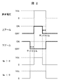
- FIG. 2 is a diagram showing a definition of dead time.
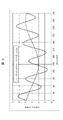
- FIG. 3 is a diagram showing a comparative example of a current waveform depending on whether or not a high frequency voltage is superimposed, and
- FIG. 4 is a diagram showing a comparative example of dead time compensation depending on whether or not a high frequency current is considered.
- the inverter In the inverter, if the upper arm and the lower arm are turned on at the same time, the DC voltage Vdc is directly applied to the IGBT, and the IGBT may be damaged. In order to prevent this, it is necessary to provide a time (dead time) for turning off both arms so that the upper arm and the lower arm do not turn on at the same time as shown in FIG.
- the voltage during the dead time is determined by the sign of the current of the motor.
- the sign of the current When the sign of the current is positive, the inverter output voltage becomes small, and conversely, when the sign of the current is negative, the inverter output voltage becomes large.
- the output voltage of the inverter is compensated according to the sign of the three-phase current.
- the dead time compensation cannot be appropriately performed due to the harmonics included in the detected current, so the current command value is used.
- high frequency voltage may be superimposed to reduce noise in the low speed range where there is a margin in output voltage.
- a high frequency current flows due to the superimposed high frequency voltage.
- the sign of the current changes due to this high frequency current, and the problem is that dead time compensation cannot be performed properly.
- the fundamental wave current is small, as shown in FIGS. 3 and 4, the sign of the current originally changes due to the high frequency current, but when the dead time compensation is performed according to the fundamental wave current command value, the dead time compensation is performed. Dead time compensation is off.
- the high frequency current value flowing by using the reverse model of the motor is estimated from the superimposed high frequency voltage, and the high frequency is higher than the fundamental wave current command value when determining the sign of the current in the dead time compensation. Add the current estimates.
- the calculation is performed using the inverse model of the motor.
- the reverse model of the motor it is possible to estimate the high frequency current with a simple calculation.
- the dead time compensation can be appropriately performed by the method of estimating the high frequency current by referring to the table.
- the dq-axis high-frequency voltage command values Vdh * and Vqh * superimpose a high-frequency component on the d-axis as in the equation (5), for example.
- the present invention may be configured by holding the amplitude Ih * and the phase ⁇ ih as a map with respect to the frequency ⁇ h of the high frequency voltage and referencing the table. The same result as is obtained.
- the magnetic pole position information is used according to the superimposed frequency ⁇ h by using a coordinate conversion means different from the fundamental wave current command value.
- the phase delay can be appropriately compensated. This makes it possible to prevent the phase of the dead time compensation from being out of phase due to the phase delay.
- the output voltage of the inverter may be compensated according to ** (estimated current for compensation for dead time). Since the high frequency voltage is superimposed to reduce noise in the low speed range where the output voltage has a margin, the dead time compensation of the inverter can be effectively performed.
- FIG. 5 is a diagram showing a modification of the dead time compensator
- FIG. 6 is a diagram showing a relationship between a dead time compensation U-phase current estimated value and a dead time compensation value in the dead time compensator of FIG. ..
- the dead time compensator (dead time compensating voltage calculation unit) 28 shown in FIG. 5 is a divider 41, 51, corresponding to each phase of the input three-phase current command values Iu **, Iv **, Iw **. It has 61, limiters 43, 53, 63 and dividers 45, 55, 65, respectively, and is dead with a predetermined inclination with respect to the three-phase current command values Iu **, Iv **, Iw **. Time compensation Three-phase voltage command values ⁇ Vu *, ⁇ Vv *, ⁇ Vw * are output.
- the dead time compensation voltage calculation unit (dead time compensator) 28 calculates according to the codes of the three-phase current command values Iu **, Iv **, and Iw **, but the dead time compensation voltage is calculated. As shown in FIGS. 5 and 6, the dead time compensation voltage is inclined with respect to the three-phase current command values Iu **, Iv **, and Iw ** so that the voltage does not switch suddenly at zero cross. It may be set as follows.
- FIG. 7 is a diagram showing another modification of the dead time compensator
- FIG. 8 is a diagram showing the relationship between the dead time compensation U-phase current estimated value and the dead time compensation value in the dead time compensator of FIG. 7. Is.
- the dead time compensator (dead time compensating voltage calculation unit) 28 shown in FIG. 7 is a divider 41, 51, corresponding to each phase of the input three-phase current command values Iu **, Iv **, Iw **. It has 61, dead zone setting units 47, 57, 67, and dividers 45, 55, 65, respectively, and the absolute values of the three-phase current command values Iu **, Iv **, and Iw ** are greater than the predetermined values. When it is small, the dead time compensation three-phase voltage command value ⁇ Vu *, ⁇ Vv *, ⁇ Vw * with a dead zone set to 0 is output.
- the three-phase current command values Iu **, Iv **, and Iw ** A method may be used in which a dead zone is provided in which the absolute value is set to 0 when the absolute value is smaller than a predetermined value.
- FIG. 9 is a diagram showing a schematic configuration of a vehicle in this embodiment.
- the vehicle of this embodiment includes a permanent magnet synchronous motor (PMSM) 1, a power converter (INV) 2, a direct current voltage source (BAT) 9, a motor control device 100, and a transmission ( The TM) 101, the differential gear (DEF) 103, the drive shaft 105, and the wheels 107 are provided.
- PMSM permanent magnet synchronous motor
- IVS power converter
- BAT direct current voltage source
- the TM the motor control device described in the first embodiment (FIG. 1) is used.
- the motor control device 100 controls the electric power supplied from the power converter (INV) 2 to the permanent magnet synchronous motor (PMSM) 1.
- a direct current voltage source (BAT) 9 such as a battery supplies power to the power converter (INV) 2.
- the permanent magnet synchronous motor (PMSM) 1 is connected to the transmission (TM) 101.
- the transmission (TM) 101 is connected to the drive shaft 105 via the differential gear (DEF) 103 to power the wheels 107.
- a method of superimposing a high frequency voltage may be used in order to reduce electromagnetic noise from the motor in the low speed range.
- the carrier frequency is high, the ratio of dead time to one cycle of PWM is relatively large, and it is also an application in which the importance of dead time compensation is high.
- the present invention is not limited to the above-described embodiment, but includes various modifications.
- the above embodiments have been described in detail to aid in understanding of the present invention and are not necessarily limited to those comprising all of the described configurations.
- it is possible to replace a part of the configuration of one embodiment with the configuration of another embodiment and it is also possible to add the configuration of another embodiment to the configuration of one embodiment.
Landscapes
- Engineering & Computer Science (AREA)
- Power Engineering (AREA)
- Life Sciences & Earth Sciences (AREA)
- Sustainable Development (AREA)
- Sustainable Energy (AREA)
- Transportation (AREA)
- Mechanical Engineering (AREA)
- Control Of Ac Motors In General (AREA)
- Inverter Devices (AREA)
Abstract
Description


図5及び図6を参照して、デッドタイム補償電圧演算部(デッドタイム補償器)28の変形例を説明する。図5は、デッドタイム補償器の変形例を示す図であり、図6は、図5のデッドタイム補償器におけるデッドタイム補償用U相電流推定値とデッドタイム補償値の関係を示す図である。
図7及び図8を参照して、デッドタイム補償電圧演算部(デッドタイム補償器)28の別の変形例を説明する。図7は、デッドタイム補償器の別の変形例を示す図であり、図8は、図7のデッドタイム補償器におけるデッドタイム補償用U相電流推定値とデッドタイム補償値の関係を示す図である。
Claims (13)
- 基本波電圧指令値に高周波電圧指令値を加算して電圧指令値を出力する高周波電圧重畳部と、
前記高周波電圧指令値から高周波電流値を推定する高周波電流推定値演算部と、
前記高周波電流推定値演算部で推定した高周波電流推定値を基本波電流指令値に加算するデッドタイム補償用電流推定値演算部と、
前記デッドタイム補償用電流推定値演算部で算出したデッドタイム補償用電流推定値に応じてインバータの出力電圧を補償するデッドタイム補償電圧演算部と、
を備える電動機制御装置。 - 請求項1に記載の電動機制御装置において、
前記高周波電流推定値演算部は、制御の対象となる電動機の逆モデルを用いて前記高周波電圧指令値から高周波電流推定値を算出する電動機制御装置。 - 請求項1または2に記載の電動機制御装置において、
座標変換に用いる位相を前記基本波電流指令値と前記高周波電流推定値で異なる値を用いる電動機制御装置。 - 請求項1に記載の電動機制御装置において、
前記デッドタイム補償電圧演算部は、入力される三相電流指令値の各相に対応するリミッタを各々有し、
前記三相電流指令値に対して所定の傾きを持たせたデッドタイム補償電圧を出力する電動機制御装置。 - 請求項1に記載の電動機制御装置において、
前記デッドタイム補償電圧演算部は、入力される三相電流指令値の各相に対応する不感帯設定部を各々有し、
前記三相電流指令値の絶対値が所定の値よりも小さい時には0にする不感帯を持たせたデッドタイム補償電圧を出力する電動機制御装置。 - 請求項1に記載の電動機制御装置において、
基本波電流が一定値以下の低電流時のみ前記デッドタイム補償用電流推定値演算部で算出したデッドタイム補償用電流推定値に応じてインバータの出力電圧を補償する電動機制御装置。 - 電動機を駆動する電動機制御装置を搭載する車両において、
請求項1から6のいずれか1項に記載の電動機制御装置を用いる車両。 - 基本波電圧指令値に高周波電圧指令値を加算して電圧指令値を出力し、
前記高周波電圧指令値から高周波電流値を推定し、
前記推定した高周波電流推定値を基本波電流指令値に加算し、
前記加算した結果に応じてインバータの出力電圧を補償する電動機制御方法。 - 請求項8に記載の電動機制御方法において、
制御の対象となる電動機の逆モデルを用いて前記高周波電圧指令値から高周波電流推定値を算出する電動機制御方法。 - 請求項8または9に記載の電動機制御方法において、
座標変換に用いる位相を前記基本波電流指令値と前記高周波電流推定値で異なる値を用いる電動機制御方法。 - 請求項8に記載の電動機制御方法において、
三相電流指令値に対して所定の傾きを持たせたデッドタイム補償電圧を出力し、前記基本波電圧指令値に加算する電動機制御方法。 - 請求項8に記載の電動機制御方法において、
三相電流指令値の絶対値が所定の値よりも小さい時には0にする不感帯を持たせたデッドタイム補償電圧を出力し、前記基本波電圧指令値に加算する電動機制御方法。 - 請求項8に記載の電動機制御方法において、
基本波電流が一定値以下の低電流時のみ前記加算した結果に応じてインバータの出力電圧を補償する電動機制御方法。
Priority Applications (3)
| Application Number | Priority Date | Filing Date | Title |
|---|---|---|---|
| CN202180049271.4A CN115843415B (zh) | 2020-09-25 | 2021-04-20 | 电动机控制装置和车辆、电动机控制方法 |
| EP21871885.6A EP4220930B1 (en) | 2020-09-25 | 2021-04-20 | Electric motor control device, vehicle, and electric motor control method |
| US18/012,419 US12212255B2 (en) | 2020-09-25 | 2021-04-20 | Electric motor control device, vehicle, and electric motor control method |
Applications Claiming Priority (2)
| Application Number | Priority Date | Filing Date | Title |
|---|---|---|---|
| JP2020-160381 | 2020-09-25 | ||
| JP2020160381A JP7525349B2 (ja) | 2020-09-25 | 2020-09-25 | 電動機制御装置および車両、電動機制御方法 |
Publications (1)
| Publication Number | Publication Date |
|---|---|
| WO2022064750A1 true WO2022064750A1 (ja) | 2022-03-31 |
Family
ID=80845166
Family Applications (1)
| Application Number | Title | Priority Date | Filing Date |
|---|---|---|---|
| PCT/JP2021/016036 Ceased WO2022064750A1 (ja) | 2020-09-25 | 2021-04-20 | 電動機制御装置および車両、電動機制御方法 |
Country Status (5)
| Country | Link |
|---|---|
| US (1) | US12212255B2 (ja) |
| EP (1) | EP4220930B1 (ja) |
| JP (1) | JP7525349B2 (ja) |
| CN (1) | CN115843415B (ja) |
| WO (1) | WO2022064750A1 (ja) |
Families Citing this family (2)
| Publication number | Priority date | Publication date | Assignee | Title |
|---|---|---|---|---|
| CN111817618B (zh) * | 2020-06-17 | 2021-07-23 | 北京航空航天大学宁波创新研究院 | 无刷电机无位置传感器换相误差补偿系统及方法 |
| JP2024022201A (ja) * | 2022-08-05 | 2024-02-16 | 日立グローバルライフソリューションズ株式会社 | インバータ装置、並びにモータ駆動装置 |
Citations (4)
| Publication number | Priority date | Publication date | Assignee | Title |
|---|---|---|---|---|
| JP2012165608A (ja) * | 2011-02-09 | 2012-08-30 | Denso Corp | 回転機の制御装置 |
| JP5401500B2 (ja) | 2011-04-19 | 2014-01-29 | 株式会社日立産機システム | 電力変換装置、電動機制御システム |
| WO2018016356A1 (ja) * | 2016-07-20 | 2018-01-25 | 日本精工株式会社 | 電動パワーステアリング装置 |
| WO2018016476A1 (ja) * | 2016-07-20 | 2018-01-25 | 日本精工株式会社 | 電動パワーステアリング装置 |
Family Cites Families (6)
| Publication number | Priority date | Publication date | Assignee | Title |
|---|---|---|---|---|
| JP3805336B2 (ja) * | 2003-10-22 | 2006-08-02 | ファナック株式会社 | 磁極位置検出装置及び方法 |
| JP5561550B2 (ja) * | 2010-11-30 | 2014-07-30 | アイシン・エィ・ダブリュ株式会社 | 回転電機制御装置 |
| JP5348153B2 (ja) * | 2011-02-14 | 2013-11-20 | 株式会社デンソー | 回転機の制御装置 |
| JP5625008B2 (ja) * | 2012-03-13 | 2014-11-12 | 株式会社日立産機システム | 電力変換装置、電動機駆動システム、搬送機、昇降装置 |
| JP2015126641A (ja) | 2013-12-27 | 2015-07-06 | 日立オートモティブシステムズ株式会社 | 電動機の制御装置 |
| JP6767213B2 (ja) * | 2016-09-05 | 2020-10-14 | 東芝インフラシステムズ株式会社 | インバータ制御装置および電動機駆動システム |
-
2020
- 2020-09-25 JP JP2020160381A patent/JP7525349B2/ja active Active
-
2021
- 2021-04-20 EP EP21871885.6A patent/EP4220930B1/en active Active
- 2021-04-20 CN CN202180049271.4A patent/CN115843415B/zh active Active
- 2021-04-20 WO PCT/JP2021/016036 patent/WO2022064750A1/ja not_active Ceased
- 2021-04-20 US US18/012,419 patent/US12212255B2/en active Active
Patent Citations (4)
| Publication number | Priority date | Publication date | Assignee | Title |
|---|---|---|---|---|
| JP2012165608A (ja) * | 2011-02-09 | 2012-08-30 | Denso Corp | 回転機の制御装置 |
| JP5401500B2 (ja) | 2011-04-19 | 2014-01-29 | 株式会社日立産機システム | 電力変換装置、電動機制御システム |
| WO2018016356A1 (ja) * | 2016-07-20 | 2018-01-25 | 日本精工株式会社 | 電動パワーステアリング装置 |
| WO2018016476A1 (ja) * | 2016-07-20 | 2018-01-25 | 日本精工株式会社 | 電動パワーステアリング装置 |
Non-Patent Citations (1)
| Title |
|---|
| See also references of EP4220930A4 |
Also Published As
| Publication number | Publication date |
|---|---|
| US12212255B2 (en) | 2025-01-28 |
| EP4220930A4 (en) | 2024-10-16 |
| JP2022053640A (ja) | 2022-04-06 |
| EP4220930A1 (en) | 2023-08-02 |
| US20230246579A1 (en) | 2023-08-03 |
| EP4220930B1 (en) | 2026-02-25 |
| CN115843415B (zh) | 2025-09-09 |
| CN115843415A (zh) | 2023-03-24 |
| JP7525349B2 (ja) | 2024-07-30 |
Similar Documents
| Publication | Publication Date | Title |
|---|---|---|
| JP3746377B2 (ja) | 交流電動機の駆動制御装置 | |
| EP2779414B1 (en) | Motor control system having bandwidth compensation | |
| CN103636117B (zh) | 逆变器控制装置及逆变器控制方法 | |
| JP7270391B2 (ja) | 電力変換装置の制御装置および電動機駆動システム | |
| JP3783695B2 (ja) | モーター制御装置 | |
| WO2008004294A1 (en) | Induction motor vector control device, induction motor vector control method, and induction motor drive control device | |
| CN101884164A (zh) | 交流电动机的控制装置 | |
| JP2011147287A (ja) | 電動機の磁極位置推定装置 | |
| JP7158573B2 (ja) | 電力変換装置およびそれを備えた電動車両システム | |
| US9419555B2 (en) | Synchronous machine control apparatus | |
| JP2013172594A (ja) | 交流電動機の制御装置 | |
| JP7525349B2 (ja) | 電動機制御装置および車両、電動機制御方法 | |
| JP3939481B2 (ja) | 交流モータの制御装置 | |
| JP2004289927A (ja) | モーター制御装置 | |
| WO2024190624A1 (ja) | モータ制御装置および電気車 | |
| JP7053335B2 (ja) | モータ制御装置、電動車両 | |
| JP2010268599A (ja) | 永久磁石モータの制御装置 | |
| JP7855139B2 (ja) | モータ制御装置 | |
| JP7385776B2 (ja) | 電動機の制御装置 | |
| EP4686078A1 (en) | Motor control device | |
| US20260045896A1 (en) | Ac motor control device, electric vehicle, and ac motor control method | |
| WO2025013499A1 (ja) | 交流モータ制御装置および電気車 | |
| JP2024122139A (ja) | 制御装置 | |
| JP2026007199A (ja) | 電動コンプレッサのモータ制御装置 | |
| WO2024043244A1 (ja) | モータ制御装置 |
Legal Events
| Date | Code | Title | Description |
|---|---|---|---|
| 121 | Ep: the epo has been informed by wipo that ep was designated in this application |
Ref document number: 21871885 Country of ref document: EP Kind code of ref document: A1 |
|
| NENP | Non-entry into the national phase |
Ref country code: DE |
|
| ENP | Entry into the national phase |
Ref document number: 2021871885 Country of ref document: EP Effective date: 20230425 |
|
| WWG | Wipo information: grant in national office |
Ref document number: 202180049271.4 Country of ref document: CN |
|
| WWG | Wipo information: grant in national office |
Ref document number: 2021871885 Country of ref document: EP |