WO2022064969A1 - 自動積込システム - Google Patents
自動積込システム Download PDFInfo
- Publication number
- WO2022064969A1 WO2022064969A1 PCT/JP2021/031755 JP2021031755W WO2022064969A1 WO 2022064969 A1 WO2022064969 A1 WO 2022064969A1 JP 2021031755 W JP2021031755 W JP 2021031755W WO 2022064969 A1 WO2022064969 A1 WO 2022064969A1
- Authority
- WO
- WIPO (PCT)
- Prior art keywords
- controller
- loading
- work machine
- control
- external system
- Prior art date
- Legal status (The legal status is an assumption and is not a legal conclusion. Google has not performed a legal analysis and makes no representation as to the accuracy of the status listed.)
- Ceased
Links
Images


Classifications
-
- E—FIXED CONSTRUCTIONS
- E02—HYDRAULIC ENGINEERING; FOUNDATIONS; SOIL SHIFTING
- E02F—DREDGING; SOIL-SHIFTING
- E02F3/00—Dredgers; Soil-shifting machines
- E02F3/04—Dredgers; Soil-shifting machines mechanically-driven
- E02F3/28—Dredgers; Soil-shifting machines mechanically-driven with digging tools mounted on a dipper- or bucket-arm, i.e. there is either one arm or a pair of arms, e.g. dippers, buckets
- E02F3/36—Component parts
- E02F3/42—Drives for dippers, buckets, dipper-arms or bucket-arms
- E02F3/43—Control of dipper or bucket position; Control of sequence of drive operations
- E02F3/435—Control of dipper or bucket position; Control of sequence of drive operations for dipper-arms, backhoes or the like
- E02F3/439—Automatic repositioning of the implement, e.g. automatic dumping, auto-return
-
- E—FIXED CONSTRUCTIONS
- E02—HYDRAULIC ENGINEERING; FOUNDATIONS; SOIL SHIFTING
- E02F—DREDGING; SOIL-SHIFTING
- E02F9/00—Component parts of dredgers or soil-shifting machines, not restricted to one of the kinds covered by groups E02F3/00 - E02F7/00
- E02F9/20—Drives; Control devices
- E02F9/2025—Particular purposes of control systems not otherwise provided for
- E02F9/205—Remotely operated machines, e.g. unmanned vehicles
-
- E—FIXED CONSTRUCTIONS
- E02—HYDRAULIC ENGINEERING; FOUNDATIONS; SOIL SHIFTING
- E02F—DREDGING; SOIL-SHIFTING
- E02F9/00—Component parts of dredgers or soil-shifting machines, not restricted to one of the kinds covered by groups E02F3/00 - E02F7/00
- E02F9/26—Indicating devices
- E02F9/261—Surveying the work-site to be treated
- E02F9/262—Surveying the work-site to be treated with follow-up actions to control the work tool, e.g. controller
-
- E—FIXED CONSTRUCTIONS
- E02—HYDRAULIC ENGINEERING; FOUNDATIONS; SOIL SHIFTING
- E02F—DREDGING; SOIL-SHIFTING
- E02F9/00—Component parts of dredgers or soil-shifting machines, not restricted to one of the kinds covered by groups E02F3/00 - E02F7/00
- E02F9/26—Indicating devices
- E02F9/264—Sensors and their calibration for indicating the position of the work tool
- E02F9/265—Sensors and their calibration for indicating the position of the work tool with follow-up actions (e.g. control signals sent to actuate the work tool)
Definitions
- the present invention relates to an automatic loading system for a work machine to automatically load a transported object into a carrier.
- Patent Document 1 describes a conventional automatic loading system.
- the controller that controls the work machine puts the work machine into a loading mode in which the work machine is operated so as to load the work machine when the approach of the carrier to the work machine is detected. (See claim 1 of the same document).
- the present invention can create room for a judgment subject other than the controller to determine whether or not the loading control can be started before the loading control is started.
- the purpose is to provide.
- the automatic loading system includes a work machine, a position detector, a controller, and an external system.
- the work machine performs a capture operation for capturing the transported object and an opening operation for loading the captured object into the transport vehicle.
- the position detection unit detects the position of the carrier with respect to the work machine.
- the controller is mounted on the work machine and can perform loading control based on the detection result of the position detection unit.
- the external system can be arranged outside the work machine and can communicate with the controller.
- the loading control is a control for causing the work machine to repeatedly perform a series of operations including the capture operation and the opening operation.
- the external system can output a loading control start signal for starting the loading control.
- the controller starts the loading control on condition that the loading control start signal is input to the controller from the external system.
- FIG. 4 is a diagram corresponding to FIG. 4, showing a display unit 71 when the position of the carrier 2 is erroneously detected. It is a figure which shows the display part 71 shown in FIG.
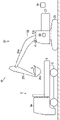
- the automatic loading system 10 for loading the transported object L into the transport vehicle 2 shown in FIG. 1 will be described with reference to FIGS. 1 to 3.
- the carrier 2 is a vehicle provided with a loading platform 5.
- the transport vehicle 2 is a vehicle for transporting the transported material L loaded by the work machine 20.
- the carrier 2 may be a dump truck or a truck.
- the carrier 2 includes a carrier main body 3 and a loading platform 5.
- the transport vehicle main body 3 is movable and supports the loading platform 5.
- the carrier main body 3 includes a carrier driver's cab 3a.
- the loading platform 5 accommodates the transported object L.
- the transported object L accommodated in the loading platform 5 may be, for example, earth and sand, stone, waste, or the like.
- the loading platform 5 may be movable with respect to the carrier main body 3, or may be fixed to the carrier main body 3.
- the automatic loading system 10 is a system that causes the work machine 20 to automatically load the transported object L into the transport vehicle 2.
- the automatic loading system 10 includes a work machine 20, a position detection unit 41, an instruction unit 42 shown in FIG. 2, a controller 50, and an external system 70.
- the work machine 20 is a machine that performs work, for example, a construction machine that performs construction work, such as a shovel.
- the work machine 20 performs a capture operation for capturing the transported object L and an opening operation for loading the captured transported object L into the transport vehicle 2 (details of the capturing operation and the opening operation will be described later).
- the work machine 20 includes a lower traveling body 21, an upper swivel body 23, an attachment 25, a drive control unit 31 shown in FIG. 2, and a posture detecting unit 33.
- the lower traveling body 21 travels the work machine 20 shown in FIG.
- the lower traveling body 21 includes, for example, a crawler.
- the upper swivel body 23 is mounted on the lower traveling body 21 so as to be swivelable.
- the upper swivel body 23 includes a work machine operation room 23a.
- the attachment 25 is undulatingly attached to the upper swivel body 23.
- the attachment 25 is a device for capturing, moving, and opening the transported object L.
- the attachment 25 includes a boom 25a, an arm 25b, and a tip attachment 25c.
- the boom 25a is attached to the upper swing body 23 so as to be undulating (rotatable up and down).
- the arm 25b is rotatably (push-pullable) attached to the boom 25a.
- the tip attachment 25c is provided at the tip of the attachment 25 and is rotatably attached to the arm 25b.
- the tip attachment 25c may be a bucket for scooping the transported object L (for example, earth and sand), or may be a device for sandwiching and grasping the transported object L (for example, a grapple).
- the drive control unit 31 controls an actuator (not shown) that drives the work machine 20. More specifically, the drive control unit 31 controls a motor for traveling the lower traveling body 21 and a motor for rotating the upper rotating body 23 with respect to the lower traveling body 21.
- the drive control unit 31 controls a cylinder that undulates the boom 25a with respect to the upper swing body 23, a cylinder that rotates the arm 25b with respect to the boom 25a, and a cylinder that rotates the tip attachment 25c with respect to the arm 25b.
- the tip attachment 25c itself operates (for example, opens and closes)
- the drive control unit 31 controls the actuator that operates the tip attachment 25c.
- the posture detection unit 33 detects the posture of the work machine 20 in order to perform the standby control C1 (step S12 in FIG. 3) and the loading control C2 (step S32 in FIG. 3) described later. More specifically, the posture detecting unit 33 detects the turning angle of the upper turning body 23 with respect to the lower traveling body 21. The posture detection unit 33 detects the rotation angle (undulation angle) of the boom 25a with respect to the upper swing body 23, the rotation angle of the arm 25b with respect to the boom 25a, and the rotation angle of the tip attachment 25c with respect to the arm 25b.
- the posture detection unit 33 may include, for example, an angle sensor for detecting the turning angle and a plurality of angle sensors for detecting the rotation angle.
- the position detection unit 41 detects the position of the carrier 2 with respect to the work machine 20. More specifically, the position detection unit 41 detects the three-dimensional position information of the carrier 2 and detects the three-dimensional shape information of the carrier 2. The position detection unit 41 may detect the position of the carrier 2 based on the three-dimensional information and the two-dimensional information (image). The position detection unit 41 may detect the position of only a part of the carrier 2, for example, the position of only the loading platform 5 of the carrier 2.
- Only one position detection unit 41 may be provided, or a plurality of position detection units 41 may be provided.
- the position detection unit 41 may be mounted on the work machine 20 or may be arranged outside the work machine 20 (for example, a work site). When the position detection unit 41 is arranged outside the work machine 20, it is possible to detect a position that cannot be detected when the position detection unit 41 is mounted only on the work machine 20 (for example, a portion behind the attachment 25). In some cases. Further, when the position detection unit 41 is arranged outside the work machine 20, the automatic loading system 10 of the present embodiment can be applied even if the position detection unit 41 is not mounted on the work machine 20. ..
- the position detection unit 41 may be provided with a device for detecting three-dimensional information using a laser beam, and may be provided with, for example, LiDAR (Light Detection and Ringing or Laser Imaging Detection and Ranking), or TOF (Time Of). A Flight) sensor may be provided.
- the position detection unit 41 may include a device (for example, a millimeter wave radar) that detects three-dimensional information using radio waves.
- the position detection unit 41 may include a stereo camera. When the position detection unit 41 detects the position of the carrier 2 based on the three-dimensional information and the two-dimensional information, the position detection unit 41 may include a camera capable of detecting a two-dimensional image.
- the instruction unit 42 gives an instruction to be described later.
- the instruction unit 42 may give an instruction perceptible to an operator (person), or may output an instruction by an electric signal (for example, an instruction for control).
- the indicator 42 gives an instruction perceptible to the operator, the indicator 42 outputs at least one of sound, light, and vibration instructions to the operator.
- the instruction unit 42 may be mounted on the work machine 20 or may be arranged outside the work machine 20.
- the indicator 42 may be provided in the external system 70.
- the indicator 42 may be a horn (for example, a horn mounted on the work machine 20), a speaker, a light, or a display device (monitor, etc.).
- the controller 50 is a computer that inputs / outputs signals, performs calculations such as determination and calculation, and stores information.
- the controller 50 is mounted on the work machine 20.
- the controller 50 can perform standby control C1 (step S12 in FIG. 3) and loading control C2 (step S32 in FIG. 3), which will be described later.
- the controller 50 controls the operation of the work machine 20 by outputting a command to the drive control unit 31 (see FIG. 2).
- the external system 70 is a computer provided separately from the controller 50.
- the external system 70 can communicate with the controller 50.
- the external system 70 can be arranged outside the work machine 20.
- the external system 70 may be, for example, one installed outside the work machine 20 (such as a server) or a portable device (such as a mobile terminal or tablet terminal).
- the external system 70 may be arranged inside the work machine 20 (for example, inside the work machine operation room 23a) as long as it can be arranged outside the work machine 20.
- the communication between the external system 70 and the controller 50 may be wireless communication or wired communication.
- the external system 70 includes a display unit 71, a standby control start instruction unit 73, a loading control start instruction unit 75, and an interruption instruction unit 77.
- the external system 70 may include an automatic determination unit 79.
- the display unit 71 displays various information.
- the display unit 71 displays for the operator to determine whether or not the controller 50 can start automatic control (specifically, the standby control C1 and the loading control C2 shown in FIG. 3) (FIG. 4). -See FIG. 6).
- the standby control start instruction unit 73 outputs the standby control start signal 73s to the external system 70.
- the standby control start signal 73s is a signal for causing the controller 50 to start the standby control C1 (see FIG. 3).
- the standby control start instruction unit 73 causes the external system 70 to output the standby control start signal 73s according to the operation of the operator.
- the operator's operation performed on the standby control start instruction unit 73 may be, for example, a touch panel operation, a physical switch operation, or a voice operation.
- the loading control start instruction unit 75 outputs the loading control start signal 75s to the external system 70.
- the loading control start signal 75s is a signal for causing the controller 50 to start the loading control C2 (see FIG. 3).
- the loading control start instruction unit 75 causes the external system 70 to output the loading control start signal 75s in response to the operation of the operator.
- the operator's operation performed on the loading control start instruction unit 75 may be, for example, a touch panel operation, a physical switch operation, or a voice operation.
- the interruption instruction unit 77 causes the controller 50 to output the interruption signal 77s for interrupting the automatic control to the external system 70.
- the interruption instruction unit 77 causes the external system 70 to output the interruption signal 77s in response to the operation of the operator.
- the operator's operation performed on the interruption instruction unit 77 may be, for example, a touch panel operation, a physical switch operation, or a voice operation.
- the interruption instruction unit 77 may cause the controller 50 to output the interruption signal 77s (standby control interruption signal) for interrupting the standby control C1 (see FIG. 3) to the external system 70.
- the interruption instruction unit 77 may cause the controller 50 to output the interruption signal 77s (loading control interruption signal) for interrupting the loading control C2 (see FIG. 3) to the external system 70.
- the automatic determination unit 79 will be described later.
- the work machine 20 shown in FIG. 1 performs a capture operation, a lift movement operation, an opening operation, and a return movement operation.
- the capture operation is an operation in which the tip attachment 25c captures the transported object L.
- the capture operation may be an operation (excavation operation) in which the bucket, which is the tip attachment 25c, excavates and scoops the earth and sand which is the transported object L.
- the capture operation may be an operation in which the tip attachment 25c sandwiches and grips the transported object L.
- the lift movement operation is an operation in which the tip attachment 25c moves (moves the transported object L) from the position where the capture operation is performed to the position where the opening operation is performed.
- the lift movement operation is an operation in which the tip attachment 25c moves along a target locus (see the target locus Qa shown in FIG. 6).
- the lift movement operation is an operation in which the upper swivel body 23 turns with respect to the lower traveling body 21 and an operation in which the tip attachment 25c moves (for example, moves upward) with respect to the upper swivel body 23. It is an operation including (lifting turning operation).
- the opening operation is an operation in which the tip attachment 25c opens the carrier L on the carrier 2 (more specifically, the loading platform 5) and loads the carrier L into the carrier 2.
- the opening operation may be an operation in which the bucket, which is the tip attachment 25c, drops the earth and sand, which is the transported object L, onto the loading platform 5 (earth removal operation).
- the opening operation may be an operation in which the tip attachment 25c releases the transported object L held by the tip attachment 25c and drops it onto the loading platform 5.
- the return movement operation is an operation in which the tip attachment 25c moves (returns) from the position where the opening operation is performed to the position where the capturing operation is performed.
- the return movement operation is an operation in which the tip attachment 25c moves along a target locus (see the target locus Qa shown in FIG. 6).
- the return movement operation includes an operation in which the upper swivel body 23 turns with respect to the lower traveling body 21 and an operation in which the tip attachment 25c moves (for example, moves downward) with respect to the upper swivel body 23. It is an operation including (return turning operation).
- the controller 50 controls the work machine 20 to operate automatically (automatic control).
- the automatic control performed by the controller 50 includes standby control C1 (see step S12 shown in FIG. 3) and loading control C2 (see step S32 shown in FIG. 3).
- standby control C1 see step S12 shown in FIG. 3
- loading control C2 see step S32 shown in FIG. 3.
- the standby control C1 (see step S12 shown in FIG. 3) is a control in which the work machine 20 shown in FIG. 1 is made to perform a capture operation, and then the work machine 20 is made to stand by in the standby posture. More specifically, the standby control C1 is a control in which the work machine 20 is made to perform a capture operation (for example, excavation), a lift movement operation (for example, turning, etc.), and is made to stand by in a standby posture.
- the above-mentioned "standby posture” is a posture for loading the captured carrier L into the carrier 2, and is a posture for waiting for an opening operation (preparatory posture).
- the standby posture is such that the work machine 20 can immediately perform the opening operation if the controller 50 outputs a command to perform the opening operation.
- the standby posture is a posture in which the tip attachment 25c (for example, a bucket containing earth and sand) that captures the transported object L is stopped at a position (in the air) where the opening operation is scheduled to be performed. (For example, the posture of waiting for soil removal).
- the posture of the work machine 20 shown in FIG. 1 is an example of a standby posture.
- the loading control C2 (see step S32 shown in FIG. 3) is a control for causing the work machine 20 to repeatedly perform a series of operations including a capture operation and an opening operation. More specifically, the loading control C2 performs a series of operations in which an opening operation (for example, soil removal), a return movement operation (for example, turning), a capturing operation (for example, excavation), and a lifting movement operation (for example, turning) are performed in this order. It is a control to be repeatedly performed by the work machine 20.
- the loading control C2 is performed based on the detection result of the position detection unit 41. At least a part of each of the loading operations (opening operation, return movement operation, capture operation, lifting operation) is performed based on the detection result of the position detection unit 41.
- the opening operation is performed as follows.
- the controller 50 calculates the three-dimensional position and shape of the loading platform 5 based on the detection result of the position detection unit 41. Then, the controller 50 causes the tip attachment 25c to open the transported object L at a specific position on the loading platform 5.
- the capture operation is performed as follows.
- the controller 50 calculates, for example, the three-dimensional position and shape of the transported object L (for example, earth and sand mountain) before capture shown in FIG. 6 based on the detection result of the position detecting unit 41.
- the controller 50 causes the tip attachment 25c to capture the transported object L at a specific position (for example, a point Qc shown in FIG. 6) before the captured object L.
- the controller 50 is based on the state of the work machine 20 immediately before the start of the loading control C2 (see FIG. 3), and the operations at the start of the loading control C2 are the opening operation, the return movement operation, the capturing operation, and the lifting operation. Determine which of the movement movements is. For example, when the loading control C2 is started while the work machine 20 is stopped in the standby posture due to the controller 50 performing the standby control C1 (see FIG. 3), the controller 50 loads the product.
- the control C2 is started from the opening operation. For example, if the loading control C2 is started in a state where the tip attachment 25c does not capture the transported object L (for example, the bucket is empty), the controller 50 returns the loading control C2 or captures the loading control C2. You may start from the operation.
- the controller 50 starts the standby control C1 on condition that the standby control start signal 73s is input from the external system 70 shown in FIG. 2 to the controller 50.
- the controller 50 starts the loading control C2 on condition that the loading control start signal 75s is input from the external system 70 to the controller 50.
- the operator confirms whether or not the standby control C1 can be started (validity). For example, the operator may confirm the presence or absence of obstacles around the position where the work machine 20 shown in FIG. 1 performs the work. For example, the operator may confirm the validity of the transported object L to be captured by the work machine 20 (the transported object L before capture shown in FIG. 6). For example, the operator may confirm the position of the transported object L before capture, or may confirm the presence / absence and the amount of the transported object L. For example, the worker may confirm the presence or absence of the transported object L carried from a belt conveyor (not shown), a machine different from the working machine 20, and the like. As shown in FIG. 6, the external system 70 may output information (for example, displayed on the display unit 71) for causing the operator to determine whether or not the standby control C1 can be started (specific example is See [Example B] to [Example E] described later).
- the operator determines that the standby control C1 (see FIG. 3) can be started, the operator operates the standby control start instruction unit 73 shown in FIG. 2 to start the standby control from the external system 70 to the controller 50.
- the signal 73s is output.
- the external system 70 does not cause the controller 50 to output the standby control start signal 73s.
- the controller 50 determines whether or not the standby control start signal 73s has been input (step S11 shown in FIG. 3).
- the controller 50 starts the standby control C1 on condition that the standby control start signal 73s is input from the external system 70 to the controller 50 (step S12 shown in FIG. 3).
- the above "condition” may be a necessary condition or a sufficient condition.
- the controller 50 may start the standby control C1 when a condition different from the input of the standby control start signal 73s is further satisfied.
- the condition for the controller 50 to start the standby control C1 shown in step S12 shown in FIG. 3 includes the input of the standby control start signal 73s from the external system 70 to the controller 50.
- the controller 50 determines the position of the carrier 2 with respect to the work machine 20 shown in FIG. 1 (step S21 shown in FIG. 3). For example, the controller 50 determines whether or not the position of the carrier 2 with respect to the work machine 20 is within a predetermined range. This "predetermined range” is set in advance in the controller 50 (prior to the determination in step S21). For example, the controller 50 determines whether or not the distance from the work machine 20 to the carrier 2 is equal to or less than the threshold value. This "threshold value" is set in advance in the controller 50 (prior to the determination in step S21). The position and distance of the carrier 2 with respect to the work machine 20 are detected by the position detection unit 41.
- step S22 If the position of the carrier 2 with respect to the work machine 20 is within a predetermined range (for example, the distance is equal to or less than the threshold value), the flow proceeds to step S22.
- the controller 50 determines the position of the carrier 2 with respect to the work machine 20 (determination in step S21 shown in FIG. 3). ) Continue.
- the timing at which the determination in step S21 shown in FIG. 3 is performed may be after the standby control C1 (step S12), before the standby control C1, or at the same time as the standby control C1.
- the timing at which the determination in step S21 is performed is before the loading control C2 (step S32).
- the carrier 2 shown in FIG. 1 may be moving toward the work machine 20.
- the controller 50 is the indicator 42 (FIG. 2) is instructed to stop.
- the above-mentioned "stop instruction" is an instruction for stopping the transport vehicle 2 moving toward the work machine 20.
- the instruction unit 42 gives a stop instruction perceptible to a person
- the driver in the carrier driver's cab 3a who perceives the stop instruction (for example, the sound of a horn) stops the carrier 2. ..
- the instruction unit 42 outputs a stop instruction by an electric signal
- the carrier 2 that has received the stop instruction may automatically stop.
- the operator confirms whether or not the loading control C2 can be started (validity).
- the operator may confirm the validity of the detection result of the position detection unit 41.
- the operator may confirm the validity of the position of the carrier 2 with respect to the work machine 20.
- the operator may confirm the validity of the position of the transported object L (see FIG. 6) before capture with respect to the working machine 20.
- the operator may confirm the validity of at least one of the target locus Qa (see FIG. 6) and the target position (for example, points Qc, point Qb, etc. shown in FIG. 6) of the tip attachment 25c in the loading control C2. ..
- the external system 70 outputs information for asking the operator to confirm whether or not the loading control C2 can be started, and displays it on, for example, the display unit 71 (step shown in FIG. 3). S23). Specific examples of the output in the external system 70 and the confirmation by the operator are as follows [Example A] to [Example E].
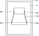
- the external system 70 shown in FIG. 1, and more specifically, the display unit 71 shown in FIG. 4 has information regarding the position of the carrier 2 (for example, the loading platform 5) with respect to the work machine 20 detected by the position detection unit 41.
- Detection position information of the carrier 2 may be displayed.
- the detection position information of the carrier 2 displayed by the external system 70 may be, for example, a point representing a specific position of the loading platform 5, a straight line or a figure indicating the range of the loading platform 5.
- the points representing the specific positions of the loading platform 5 may include, for example, four points P5a, P5b, P5c, and P5d indicating the four corners of the loading platform 5.
- the external system 70 may display a value related to the detection position information of the carrier 2.
- the value regarding the detection position information of the carrier 2 may include, for example, at least one of the coordinates and the distance of the carrier 2 with respect to the work machine 20.
- the external system 70 superimposes and displays the detection position information of the carrier 2 and the two-dimensional image of the carrier 2 (for example, the image of the loading platform 5). The operator who sees this display determines the validity of the detected position information by comparing the detected position information of the carrier 2 with the two-dimensional image.
- the operator has a portion corresponding to the detection position information of the carrier 2 (for example, four points P5a, P5b, P5c, P5d) and the detection position information in the two-dimensional image of the carrier 2 (for example, a loading platform). (Positions of the four corners of 5) and check whether they match or substantially match. When these match or substantially match, the operator can determine that the detection result of the position detection unit 41 shown in FIG. 1 is appropriate. When these are largely deviated (see FIG. 5), the operator can determine that the detection result of the position detection unit 41 is not valid.
- the detection position information of the carrier 2 for example, four points P5a, P5b, P5c, P5d
- the detection position information in the two-dimensional image of the carrier 2 for example, a loading platform.
- the external system 70 may display information (detection position information of the transported object L) regarding the position of the transported object L with respect to the work machine 20 detected by the position detecting unit 41 (see FIG. 1). ..
- the external system 70 may display information regarding the position of the transported object L (for example, a landslide) before being captured by the work machine 20.
- the detected position information of the transported object L displayed by the external system 70 may be, for example, a point representing a specific position of the transported object L, or a figure indicating the range of the transported object L.
- the point representing the specific position of the transported object L may include, for example, the point Ra representing the apex.
- the external system 70 may display a value related to the detection position information of the transported object L.
- the value regarding the detection position information of the transported object L may include at least one of the coordinates and the distance of the transported object L with respect to the work machine 20. Similar to the above [Example A], the external system 70 superimposes and displays the detection position information of the transported object L and the two-dimensional image of the transported object L. The operator who sees this display can judge the validity of the detection result of the position detection unit 41.
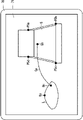
- the external system 70 may display information regarding the target locus Qa in the loading control C2 (see FIG. 3).
- the target locus Qa is a target locus of the tip attachment 25c between the position where the capture operation is performed (point Qc) and the position where the opening operation is performed (point Qb), and is calculated by the controller 50.
- the external system 70 may display information about the target locus Qa in the lift movement operation, or may display information about the target locus Qa in the return movement operation.
- the external system 70 sets the target locus. The correction result of Qa may be displayed.
- the external system 70 may superimpose and display the information about the target locus Qa and the two-dimensional image of the position where the attachment 25 is expected to pass. The operator who sees this display can judge the validity of the information regarding the target locus Qa as in the above [Example A].
- the external system 70 may display information regarding the target loading position (point Qb) in the loading control C2.
- the target loading position (point Qb) is a target position where the work machine 20 shown in FIG. 1 performs an opening operation, and is calculated by the controller 50.
- the external system 70 may display the target loading position (point Qb).
- the external system 70 automatically corrects the target loading position (point Qb) according to the position of the transport vehicle 2 detected by the position detection unit 41, or manually corrects the target loading position (point Qb). When is corrected, the correction result of the target loading position (point Qb) may be displayed.
- the external system 70 may superimpose and display the information on the target loading position (point Qb) and the two-dimensional image of the carrier 2 (for example, the loading platform 5). A worker who sees this display can determine whether or not the target loading position (point Qb) is appropriate (for example, whether or not it is an appropriate position on the loading platform 5).
- the external system 70 may display information regarding the target acquisition position (point Qc) in the loading control C2.
- the target capture position (point Qc) is a target position where the work machine 20 shown in FIG. 1 performs a capture operation, and is calculated by the controller 50.
- the external system 70 may display the target acquisition position (point Qc).
- the external system 70 automatically corrects the target acquisition position (point Qc) according to the position of the transported object L detected by the position detection unit 41, or manually corrects the target acquisition position (point Qc). If so, the correction result of the target acquisition position (point Qc) may be displayed.
- the external system 70 may superimpose and display the information regarding the target acquisition position (point Qc) and the two-dimensional image of the transported object L before acquisition. The operator who sees this display can determine whether or not the target acquisition position (point Qc) is appropriate (for example, whether or not it is an appropriate position in the transported object L before acquisition).
- step S32 When the operator determines that the loading control C2 (step S32) shown in FIG. 3 can be started, the operator operates the loading control start instruction unit 75 shown in FIG. 2 to control the controller from the external system 70.
- the loading control start signal 75s is output to 50.
- the external system 70 does not cause the controller 50 to output the loading control start signal 75s.
- the controller 50 determines whether or not the loading control start signal 75s has been input (step S31 shown in FIG. 3).
- the controller 50 starts the loading control C2 on condition that the loading control start signal 75s is input from the external system 70 to the controller 50 (step S32 shown in FIG. 3).
- the above "condition” may be a necessary condition or a sufficient condition.
- the controller 50 may start the loading control C2 when a condition (additional condition) different from the input of the loading control start signal 75s is further satisfied.
- the condition for the controller 50 to start the loading control C2 includes that the loading control start signal 75s is input to the controller 50 from the external system 70.
- additional condition may be, for example, that the position of the carrier 2 with respect to the work machine 20 shown in FIG. 1 is within a predetermined range (YES in step S21 shown in FIG. 3).
- the additional condition may be that the stop instruction for the carrier 2 (step S22 shown in FIG. 3) is completed.
- the controller 50 determines whether or not to terminate the loading control C2 while the loading control C2 is being performed (step S41 shown in FIG. 3). For example, the controller 50 ends the loading control C2 when the amount of the transported object L loaded on the transport vehicle 2 exceeds a predetermined amount. The amount of the transported object L loaded on the carrier 2 may be detected by the position detection unit 41 or may be detected by a sensor other than the position detection unit 41. For example, the controller 50 may suspend the loading control C2 when the interruption signal 77s is input from the external system 70 shown in FIG. When the controller 50 determines that the loading control C2 is not terminated, the controller 50 continues the loading control C2. When the loading control C2 is interrupted, the controller 50 may restart the loading control C2 when a signal for restarting the loading control C2 (for example, the loading control start signal 75s) is input.
- a signal for restarting the loading control C2 for example, the loading control start signal 75s
- the controller 50 When the loading control C2 is terminated (YES in step S41 shown in FIG. 3), the controller 50 notifies that the loading control C2 is terminated (this notification is referred to as a termination notification).
- the controller 50 causes the instruction unit 42 to output a completion notification.
- the instruction unit 42 gives an instruction perceptible to a person (for example, a horn)
- the driver of the carrier 2 shown in FIG. 1 perceives the end notification (for example, hears the sound of the horn ringing).
- the carrier 2 may be driven (departed).
- the instruction unit 42 outputs an end notification by an electric signal, the transport vehicle 2 that has received the end notification may automatically travel (depart).
- the external system 70 may receive the end notification from the controller 50 and output that the loading is completed.
- the display unit 71 may display that the loading has been completed.
- the instruction unit 42 that gives a stop instruction (see step S22 shown in FIG. 3) and the instruction unit 42 that gives an end notification (see step S42 shown in FIG. 3) may or may not be used together. ..
- the external system 70 may include an automatic determination unit 79 that automatically determines the validity of starting the automatic control.
- the automatic determination unit 79 determines the validity of starting the automatic control by using, for example, AI (Artificial Intelligence).
- AI Artificial Intelligence
- the automatic determination unit 79 determines that the start of the standby control C1 is not appropriate, the automatic determination unit 79 does not output the standby control start signal 73s to the external system 70.
- the automatic determination unit 79 determines that the start of the loading control C2 is appropriate, the automatic determination unit 79 outputs the loading control start signal 75s to the external system 70. If the automatic determination unit 79 determines that the start of the loading control C2 is not appropriate, the automatic determination unit 79 does not output the loading control start signal 75s to the external system 70.
- the automatic determination unit 79 (see FIG. 2) automatically performs this comparison by, for example, image processing. Then, when the automatic determination unit 79 determines that the start of the loading control C2 is appropriate, the automatic determination unit 79 causes the external system 70 to output the loading control start signal 75s. The same applies to the above [Example B] to [Example E].
- the automatic determination unit 79 can be omitted.
- the effects of the automatic loading system 10 shown in FIG. 1 are as follows.
- the automatic loading system 10 includes a work machine 20, a position detection unit 41, a controller 50, and an external system 70.
- the work machine 20 performs a capturing operation for capturing the transported object L and an opening operation for loading the captured transported object L into the transport vehicle 2.
- the position detection unit 41 detects the position of the carrier 2 with respect to the work machine 20.
- the controller 50 is mounted on the work machine 20 and can perform loading control C2 (see step S32 shown in FIG. 3) based on the detection result of the position detection unit 41.
- the external system 70 can be arranged outside the work machine 20 and can communicate with the controller 50.
- the loading control C2 is a control for causing the work machine 20 to repeatedly perform a series of operations including a capture operation and an opening operation.
- the external system 70 can output the loading control start signal 75s for starting the loading control C2.
- the controller 50 starts the loading control C2 on condition that the loading control start signal 75s is input from the external system 70 to the controller 50.
- the loading control C2 is not started unless the loading control start signal 75s is input from the external system 70 to the controller 50. Therefore, before the loading control C2 is started, it is possible to create room for a judgment subject other than the controller 50 to judge whether or not the loading control C2 can be started.
- the loading control C2 is performed based on the detection result of the position detection unit 41, and the validity of the detection result of the position detection unit 41 can be determined by a judgment subject other than the controller 50.
- the determination subject other than the controller 50 may include at least one of the worker (person) and the automatic determination unit 79 (for example, AI).
- the controller 50 can perform standby control C1 (see step S12 shown in FIG. 3).
- the standby control C1 is a control in which the work machine 20 shown in FIG. 1 is made to perform a capture operation, and the work machine 20 is made to stand by in a specific posture for loading the captured carrier L into the carrier 2.
- the external system 70 can output the standby control start signal 73s for starting the standby control C1.
- the controller 50 starts the standby control C1 on condition that the standby control start signal 73s is input from the external system 70 to the controller 50.
- the standby control C1 is not started unless the standby control start signal 73s is input from the external system 70 to the controller 50. Therefore, before the standby control C1 shown in FIG. 3 is started, it is possible to create room for a determination entity other than the controller 50 shown in FIG. 2 to determine whether or not the standby control C1 can be started. ..
- the external system 70 outputs different types of signals (standby control start signal 73s and loading control start signal 75s). Therefore, by changing the type of the signal output by the external system 70, the external system 70 starts the start of a plurality of types of automatic control (specifically, the standby control C1 and the loading control C2 shown in FIG. 3) by the controller 50. Can be instructed to.
- the external system 70 displays information regarding the position of the carrier 2 detected by the position detection unit 41 (see FIG. 1).
- the external system 70 can make the operator confirm the validity of the information regarding the position of the carrier 2 detected by the position detection unit 41. Therefore, the operator can easily determine whether or not the automatic control (standby control C1 or loading control C2 shown in FIG. 3) can be started.
- the external system 70 displays information regarding a position (loading position (point Qb)) at which the work machine 20 loads the transported object L into the transport vehicle 2.
- the external system 70 can make the operator confirm the validity of the information regarding the loading position (point Qb) of the transported object L. Therefore, the operator can easily determine whether or not the automatic control (standby control C1 or loading control C2 shown in FIG. 3) can be started.
- the work machine 20 includes a tip attachment 25c for capturing, moving, and opening the transported object L.
- the external system 70 displays information about the target locus Qa of the tip attachment 25c between the position where the capture operation is performed and the position where the opening operation is performed.
- the external system 70 allows the operator to confirm the information regarding the target locus Qa of the attachment 25. Therefore, the operator can easily determine whether or not the automatic control (standby control C1 or loading control C2 shown in FIG. 3) can be started.
- the above embodiment may be variously modified.
- the arrangement, shape, connection, and the like of each component of the above embodiment may be changed.
- the order of the steps in the flowchart shown in FIG. 3 may be changed, or a part of the steps may not be performed.
- the threshold value, range, and the like may be constant, may be changed manually, or may be automatically changed according to some condition.
- the number of components may be changed and some of the components may not be provided.
- what is described as a plurality of different parts may be regarded as one part.
- what has been described as one part may be provided separately in a plurality of different parts.
- the external system 70 may be a single system or may be divided into a plurality of parts.
- the external system 70 includes a portion (for example, a tablet terminal) including a display unit 71, a standby control start instruction unit 73, a loading control start instruction unit 75, and an interruption instruction unit 77, and an automatic determination unit 79 (for example, it may be provided separately from the server).
Landscapes
- Engineering & Computer Science (AREA)
- Mining & Mineral Resources (AREA)
- Civil Engineering (AREA)
- General Engineering & Computer Science (AREA)
- Structural Engineering (AREA)
- Mechanical Engineering (AREA)
- Operation Control Of Excavators (AREA)
- Component Parts Of Construction Machinery (AREA)
- Control Of Position, Course, Altitude, Or Attitude Of Moving Bodies (AREA)
- Control And Safety Of Cranes (AREA)
Abstract
コントローラ(50)は、作業機械(20)に搭載され、位置検出部(41)の検出結果に基づく積込制御を行うことが可能である。外部システム(70)は、作業機械(20)の外部に配置可能であり、コントローラ(50)と通信可能である。外部システム(70)は、積込制御を開始させるための積込制御開始信号を出力可能である。コントローラ(50)は、外部システム(70)からコントローラ(50)に積込制御開始信号が入力されたことを条件として、積込制御を開始する。
Description
本発明は、作業機械が運搬車に運搬物を自動的に積み込むための自動積込システムに関する。
例えば特許文献1などに、従来の自動積込システムが記載されている。同文献に記載の技術では、作業機械を制御するコントローラは、作業機械への運搬車の接近を検知したときに、運搬車への積込を行うように作業機械を動作させる積込モードにする(同文献の請求項1を参照)。
同文献に記載の技術では、作業機械が運搬車への積込を行うのに適した状態でなくても、例えば運搬車が接近していることが誤検知されれば、積込を行う制御(積込制御)が行われてしまう。
そこで、本発明は、積込制御が開始される前に、積込制御が開始可能な状況であるか否かを、コントローラ以外の判断主体に判断させる余地を生み出すことができる、自動積込システムを提供することを目的とする。
自動積込システムは、作業機械と、位置検出部と、コントローラと、外部システムと、を備える。前記作業機械は、運搬物を捕捉する捕捉動作、および、捕捉した前記運搬物を運搬車に積み込む開放動作を行う。前記位置検出部は、前記作業機械に対する前記運搬車の位置を検出する。前記コントローラは、前記作業機械に搭載され、前記位置検出部の検出結果に基づく積込制御を行うことが可能である。前記外部システムは、前記作業機械の外部に配置可能であり、前記コントローラと通信可能である。前記積込制御は、前記捕捉動作と前記開放動作とを含む一連の動作を前記作業機械に繰り返し行わせる制御である。前記外部システムは、前記積込制御を開始させるための積込制御開始信号を出力可能である。前記コントローラは、前記外部システムから前記コントローラに前記積込制御開始信号が入力されたことを条件として、前記積込制御を開始する。
図1~図3を参照して、図1に示す運搬車2に運搬物Lを積み込むための自動積込システム10について説明する。
運搬車2は、荷台5を備える車両である。運搬車2は、作業機械20によって積み込まれた運搬物Lを輸送するための車両である。運搬車2は、ダンプカーでもよく、トラックでもよい。運搬車2は、運搬車本体部3と、荷台5と、を備える。運搬車本体部3は、走行可能であり、荷台5を支持する。運搬車本体部3は、運搬車運転室3aを備える。荷台5は、運搬物Lを収容する。荷台5に収容される運搬物Lは、例えば土砂でもよく、石でもよく、廃棄物などでもよい。荷台5は、運搬車本体部3に対して可動でもよく、運搬車本体部3に固定されてもよい。
自動積込システム10は、運搬車2に運搬物Lを積み込む作業を作業機械20に自動的に行わせるシステムである。自動積込システム10は、作業機械20と、位置検出部41と、図2に示す指示部42と、コントローラ50と、外部システム70と、を備える。
作業機械20は、図1に示すように、作業を行う機械であり、例えば建設作業を行う建設機械であり、例えばショベルなどである。作業機械20は、運搬物Lを捕捉する捕捉動作、および、捕捉した運搬物Lを運搬車2に積み込む開放動作を行う(捕捉動作および開放動作の詳細は後述される)。作業機械20は、下部走行体21と、上部旋回体23と、アタッチメント25と、図2に示す駆動制御部31と、姿勢検出部33と、を備える。
下部走行体21は、図1に示す作業機械20を走行させる。下部走行体21は、例えばクローラを備える。上部旋回体23は、下部走行体21に旋回可能に搭載される。上部旋回体23は、作業機械運転室23aを備える。
アタッチメント25は、上部旋回体23に起伏可能に取り付けられる。アタッチメント25は、運搬物Lの捕捉、移動、および開放を行う装置である。アタッチメント25は、ブーム25aと、アーム25bと、先端アタッチメント25cと、を備える。ブーム25aは、上部旋回体23に起伏可能(上下に回転可能)に取り付けられる。アーム25bは、ブーム25aに回転可能(押し引き可能)に取り付けられる。先端アタッチメント25cは、アタッチメント25の先端部に設けられ、アーム25bに回転可能に取り付けられる。先端アタッチメント25cは、運搬物L(例えば土砂など)をすくうバケットでもよく、運搬物Lを挟んで掴む装置(例えばグラップルなど)でもよい。
駆動制御部31(図2参照)は、作業機械20を駆動させるアクチュエータ(図示なし)を制御する。さらに詳しくは、駆動制御部31は、下部走行体21を走行させるモータ、および、下部走行体21に対して上部旋回体23を旋回させるモータを制御する。駆動制御部31は、上部旋回体23に対してブーム25aを起伏させるシリンダ、ブーム25aに対してアーム25bを回転させるシリンダ、および、アーム25bに対して先端アタッチメント25cを回転させるシリンダを制御する。先端アタッチメント25c自体が作動(例えば開閉)する場合、駆動制御部31は、先端アタッチメント25cを作動させるアクチュエータを制御する。
姿勢検出部33(図2参照)は、後述する待機制御C1(図3のステップS12)および積込制御C2(図3のステップS32)を行うために、作業機械20の姿勢を検出する。さらに詳しくは、姿勢検出部33は、下部走行体21に対する上部旋回体23の旋回角度を検出する。姿勢検出部33は、上部旋回体23に対するブーム25aの回転角度(起伏角度)、ブーム25aに対するアーム25bの回転角度、および、アーム25bに対する先端アタッチメント25cの回転角度を検出する。姿勢検出部33は、例えば前記旋回角度を検出する角度センサと、前記回転角度を検出する複数の角度センサと、を含んでいてもよい。
位置検出部41は、作業機械20に対する運搬車2の位置を検出する。さらに詳しくは、位置検出部41は、運搬車2の三次元の位置情報を検出し、運搬車2の三次元の形状情報を検出する。位置検出部41は、三次元の情報と二次元の情報(画像)とに基づいて、運搬車2の位置を検出してもよい。位置検出部41は、運搬車2の一部のみの位置を検出してもよく、例えば運搬車2のうち荷台5のみの位置を検出してもよい。
この位置検出部41は、1つのみ設けられてもよく、複数設けられてもよい。位置検出部41は、作業機械20に搭載されてもよく、作業機械20の外部(例えば作業現場)に配置されてもよい。位置検出部41が作業機械20の外部に配置される場合は、位置検出部41が作業機械20のみに搭載された場合には検出できない位置(例えばアタッチメント25の陰になる部分など)を検出できる場合がある。また、位置検出部41が作業機械20の外部に配置される場合は、作業機械20に位置検出部41が搭載されていなくても、本実施形態の自動積込システム10を適用することができる。
この位置検出部41は、レーザー光を用いて三次元の情報を検出する装置を備えてもよく、例えばLiDAR(Light Detection and RangingまたはLaser Imaging Detection and Ranging)を備えてもよく、TOF(Time Of Flight)センサを備えてもよい。位置検出部41は、電波を用いて三次元の情報を検出する装置(例えばミリ波レーダなど)を備えてもよい。位置検出部41は、ステレオカメラを備えてもよい。位置検出部41が三次元の情報と二次元の情報とに基づいて運搬車2の位置を検出する場合は、位置検出部41は、二次元の画像を検出可能なカメラを備えてもよい。
指示部42(図2参照)は、後述する指示を行う。指示部42は、作業者(人)が知覚可能な指示を行ってもよく、電気信号による指示(例えば制御のための指示など)を出力してもよい。作業者が知覚可能な指示を指示部42が行う場合、指示部42は、作業者に音、光、および振動の少なくともいずれかの指示を出力する。指示部42は、作業機械20に搭載されてもよく、作業機械20の外部に配置されてもよい。指示部42は、外部システム70に設けられてもよい。指示部42は、ホーン(例えば作業機械20に搭載されたホーンなど)でもよく、スピーカでもよく、ライトでもよく、表示装置(モニタなど)でもよい。
コントローラ50は、信号の入出力、判定や算出などの演算、情報の記憶などを行うコンピュータである。コントローラ50は、作業機械20に搭載される。コントローラ50は、後述する待機制御C1(図3のステップS12)と、積込制御C2(図3のステップS32)と、を行うことが可能である。コントローラ50は、駆動制御部31(図2参照)に指令を出力することで、作業機械20の作動を制御する。
外部システム70は、コントローラ50とは別に設けられるコンピュータである。外部システム70は、コントローラ50と通信可能である。外部システム70は、作業機械20の外部に配置可能である。外部システム70は、例えば、作業機械20の外部に設置されたもの(サーバなど)でもよく、携帯可能な装置(携帯端末、タブレット端末など)でもよい。なお、外部システム70は、作業機械20の外部に配置可能であればよく、作業機械20の内部(例えば作業機械運転室23aの内部)に配置されてもよい。外部システム70とコントローラ50との通信は、無線通信でもよく、有線通信でもよい。図2に示すように、外部システム70は、表示部71と、待機制御開始指示部73と、積込制御開始指示部75と、中断指示部77と、を備える。外部システム70は、自動判断部79を備えてもよい。
表示部71は、各種情報を表示する。表示部71は、コントローラ50が自動制御(具体的には図3に示す待機制御C1および積込制御C2)を開始可能な状況か否かを作業者に判断させるための表示を行う(図4~図6を参照)。
待機制御開始指示部73は、待機制御開始信号73sを外部システム70に出力させる。待機制御開始信号73sは、コントローラ50に待機制御C1(図3参照)を開始させるための信号である。待機制御開始指示部73は、作業者の操作に応じて、待機制御開始信号73sを外部システム70に出力させる。待機制御開始指示部73に対して行われる前記作業者の操作は、例えば、タッチパネルの操作でもよく、物理スイッチの操作でもよく、音声操作でもよい。
積込制御開始指示部75は、積込制御開始信号75sを外部システム70に出力させる。積込制御開始信号75sは、コントローラ50に積込制御C2(図3参照)を開始させるための信号である。積込制御開始指示部75は、作業者の操作に応じて、積込制御開始信号75sを外部システム70に出力させる。積込制御開始指示部75に対して行われる前記作業者の操作は、例えば、タッチパネルの操作でもよく、物理スイッチの操作でもよく、音声操作でもよい。
中断指示部77は、コントローラ50に自動制御を中断させるための中断信号77sを、外部システム70に出力させる。中断指示部77は、作業者の操作に応じて、中断信号77sを外部システム70に出力させる。中断指示部77に対して行われる前記作業者の操作は、例えば、タッチパネルの操作でもよく、物理スイッチの操作でもよく、音声操作でもよい。中断指示部77は、コントローラ50に待機制御C1(図3参照)を中断させるための中断信号77s(待機制御中断信号)を、外部システム70に出力させてもよい。中断指示部77は、コントローラ50に積込制御C2(図3参照)を中断させるための中断信号77s(積込制御中断信号)を、外部システム70に出力させてもよい。なお、自動判断部79については後述する。
(作業機械20の動作)
図1に示す作業機械20は、捕捉動作、持上移動動作、開放動作、および復帰移動動作を行う。
図1に示す作業機械20は、捕捉動作、持上移動動作、開放動作、および復帰移動動作を行う。
捕捉動作は、先端アタッチメント25cが運搬物Lを捕捉する動作である。例えば、捕捉動作は、先端アタッチメント25cであるバケットが、運搬物Lである土砂を、掘削してすくう動作(掘削動作)でもよい。例えば、捕捉動作は、先端アタッチメント25cが運搬物Lを挟んで掴む動作でもよい。
持上移動動作は、捕捉動作を行った位置から開放動作を行う位置に、先端アタッチメント25cが移動する(運搬物Lを移動させる)動作である。持上移動動作は、先端アタッチメント25cが、目標とする軌跡(図6に示す目標軌跡Qaを参照)に沿って移動する動作である。具体的には例えば、持上移動動作は、下部走行体21に対して上部旋回体23が旋回する動作と、上部旋回体23に対して先端アタッチメント25cが移動(例えば上などに移動)する動作と、を含む動作(持上旋回動作)である。
開放動作は、先端アタッチメント25cが、運搬車2(さらに詳しくは荷台5)の上で運搬物Lを開放し、運搬車2に運搬物Lを積み込む動作である。例えば、開放動作は、先端アタッチメント25cであるバケットが、運搬物Lである土砂を、荷台5に落下させる動作(排土動作)でもよい。例えば、開放動作は、先端アタッチメント25cが、挟んで掴んでいた運搬物Lを開放し、荷台5に落下させる動作でもよい。
復帰移動動作は、開放動作を行った位置から捕捉動作を行う位置に先端アタッチメント25cが移動する(復帰する)動作である。復帰移動動作は、先端アタッチメント25cが、目標とする軌跡(図6に示す目標軌跡Qaを参照)に沿って移動する動作である。具体的には例えば、復帰移動動作は、下部走行体21に対して上部旋回体23が旋回する動作と、上部旋回体23に対して先端アタッチメント25cが移動(例えば下などに移動)する動作と、を含む動作(復帰旋回動作)である。
(コントローラ50による自動制御)
コントローラ50は、作業機械20を自動的に動作させる制御(自動制御)を行う。コントローラ50が行う自動制御には、待機制御C1(図3に示すステップS12を参照)と、積込制御C2(図3に示すステップS32を参照)と、がある。以下では、作業機械20については主に図1を参照し、フローチャートの各ステップ、待機制御C1、および積込制御C2については図3を参照して説明する。
コントローラ50は、作業機械20を自動的に動作させる制御(自動制御)を行う。コントローラ50が行う自動制御には、待機制御C1(図3に示すステップS12を参照)と、積込制御C2(図3に示すステップS32を参照)と、がある。以下では、作業機械20については主に図1を参照し、フローチャートの各ステップ、待機制御C1、および積込制御C2については図3を参照して説明する。
待機制御C1(図3に示すステップS12を参照)は、図1に示す作業機械20に捕捉動作を行わせた後、作業機械20を待機姿勢で待機させる制御である。さらに詳しくは、待機制御C1は、作業機械20に、捕捉動作(例えば掘削)を行わせ、持上移動動作(例えば旋回など)を行わせ、待機姿勢で待機させる制御である。上記「待機姿勢」は、捕捉した運搬物Lを運搬車2に積み込むための姿勢であり、開放動作を待機する姿勢(事前準備姿勢)である。待機姿勢は、コントローラ50が開放動作を行う指令を出力すれば作業機械20が即座に開放動作を行えるような姿勢である。具体的には例えば、待機姿勢は、運搬物Lを捕捉している先端アタッチメント25c(例えば土砂が入っているバケット)が、開放動作を行うことが予定されている位置(空中)で停止した姿勢である(例えば排土待機姿勢)。図1に示す作業機械20の姿勢は、待機姿勢の一例である。
積込制御C2(図3に示すステップS32を参照)は、捕捉動作と、開放動作と、を含む一連の動作を作業機械20に繰り返し行わせる制御である。さらに詳しくは、積込制御C2は、開放動作(例えば排土)、復帰移動動作(例えば旋回)、捕捉動作(例えば掘削)、持上移動動作(例えば旋回)、の順に行われる一連の動作を作業機械20に繰り返し行わせる制御である。積込制御C2は、位置検出部41の検出結果に基づいて行われる。積込動作の各動作(開放動作、復帰移動動作、捕捉動作、持上移動動作)のうち、少なくとも一部が、位置検出部41の検出結果に基づいて行われる。具体的には例えば、開放動作は、次のように行われる。コントローラ50は、位置検出部41の検出結果に基づいて荷台5の三次元の位置および形状を算出する。そして、コントローラ50は、荷台5の上の特定の位置で、先端アタッチメント25cに運搬物Lを開放させる。具体的には例えば、捕捉動作は、次のように行われる。コントローラ50は、位置検出部41の検出結果に基づいて、例えば図6に示す捕捉前の運搬物L(例えば土砂山など)の三次元の位置および形状を算出する。そして、コントローラ50は、捕捉前の運搬物Lの特定の位置(例えば図6に示す点Qcなど)で、先端アタッチメント25cに運搬物Lを捕捉させる。
コントローラ50は、積込制御C2(図3参照)の開始直前の作業機械20の状態に基づいて、積込制御C2の開始時の動作が、開放動作、復帰移動動作、捕捉動作、および持上移動動作のうち、どの動作であるかを決定する。例えば、コントローラ50が待機制御C1(図3参照)を行ったことなどにより、作業機械20が待機姿勢で停止している状態で積込制御C2が開始される場合は、コントローラ50は、積込制御C2を開放動作から開始させる。例えば、先端アタッチメント25cが運搬物Lを捕捉していない状態(例えばバケットが空の状態)で、積込制御C2が開始される場合は、コントローラ50は、積込制御C2を復帰移動動作または捕捉動作から開始させてもよい。
(自動制御の開始の条件など)
コントローラ50は、図2に示す外部システム70からコントローラ50に待機制御開始信号73sが入力されたことを条件として、待機制御C1を開始する。コントローラ50は、外部システム70からコントローラ50に積込制御開始信号75sが入力されたことを条件として、積込制御C2を開始する。自動積込システム10の作動などを、図3に示すフローチャートを参照して説明する。
コントローラ50は、図2に示す外部システム70からコントローラ50に待機制御開始信号73sが入力されたことを条件として、待機制御C1を開始する。コントローラ50は、外部システム70からコントローラ50に積込制御開始信号75sが入力されたことを条件として、積込制御C2を開始する。自動積込システム10の作動などを、図3に示すフローチャートを参照して説明する。
(待機制御C1の開始の妥当性の確認)
コントローラ50が待機制御C1を開始する前に、作業者が、待機制御C1を開始可能な状況か否か(妥当性)を確認する。例えば、作業者は、図1に示す作業機械20が作業を行う位置の周囲の障害物の有無を確認してもよい。例えば、作業者は、作業機械20に捕捉させようとする運搬物L(図6に示す捕捉前の運搬物L)に関する妥当性を確認してもよい。例えば、作業者は、捕捉前の運搬物Lの位置を確認してもよく、運搬物Lの有無や量を確認してもよい。例えば、作業者は、ベルトコンベア(図示なし)や作業機械20とは異なる機械などから運ばれてきた運搬物Lの有無を確認してもよい。図6に示すように、外部システム70は、待機制御C1を開始可能な状況か否かを作業者に判断させるための情報を出力(例えば表示部71に表示)してもよい(具体例は後述する[例B]~[例E]を参照)。
コントローラ50が待機制御C1を開始する前に、作業者が、待機制御C1を開始可能な状況か否か(妥当性)を確認する。例えば、作業者は、図1に示す作業機械20が作業を行う位置の周囲の障害物の有無を確認してもよい。例えば、作業者は、作業機械20に捕捉させようとする運搬物L(図6に示す捕捉前の運搬物L)に関する妥当性を確認してもよい。例えば、作業者は、捕捉前の運搬物Lの位置を確認してもよく、運搬物Lの有無や量を確認してもよい。例えば、作業者は、ベルトコンベア(図示なし)や作業機械20とは異なる機械などから運ばれてきた運搬物Lの有無を確認してもよい。図6に示すように、外部システム70は、待機制御C1を開始可能な状況か否かを作業者に判断させるための情報を出力(例えば表示部71に表示)してもよい(具体例は後述する[例B]~[例E]を参照)。
作業者は、待機制御C1(図3参照)を開始可能な状況であると判断した場合、図2に示す待機制御開始指示部73を操作することで、外部システム70からコントローラ50に待機制御開始信号73sを出力させる。作業者は、待機制御C1を開始可能な状況でないと判断した場合、外部システム70からコントローラ50に待機制御開始信号73sを出力させない。
(コントローラ50の作動など)
コントローラ50は、待機制御開始信号73sが入力されたか否かを判定する(図3に示すステップS11)。コントローラ50は、外部システム70からコントローラ50に待機制御開始信号73sが入力されたことを条件として、待機制御C1を開始する(図3に示すステップS12)。上記「条件」は、必要条件でも、十分条件でもよい。コントローラ50は、待機制御開始信号73sが入力されたこととは異なる条件がさらに満たされた場合に、待機制御C1を開始してもよい。コントローラ50が図3に示すステップS12に示す待機制御C1を開始する条件は、外部システム70からコントローラ50に待機制御開始信号73sが入力されたことを含む。
コントローラ50は、待機制御開始信号73sが入力されたか否かを判定する(図3に示すステップS11)。コントローラ50は、外部システム70からコントローラ50に待機制御開始信号73sが入力されたことを条件として、待機制御C1を開始する(図3に示すステップS12)。上記「条件」は、必要条件でも、十分条件でもよい。コントローラ50は、待機制御開始信号73sが入力されたこととは異なる条件がさらに満たされた場合に、待機制御C1を開始してもよい。コントローラ50が図3に示すステップS12に示す待機制御C1を開始する条件は、外部システム70からコントローラ50に待機制御開始信号73sが入力されたことを含む。
コントローラ50は、図1に示す作業機械20に対する運搬車2の位置に関する判定を行う(図3に示すステップS21)。例えば、コントローラ50は、作業機械20に対する運搬車2の位置が、所定の範囲内か否かを判定する。この「所定の範囲」は、予め(ステップS21の判定より前に)コントローラ50に設定される。例えば、コントローラ50は、作業機械20から運搬車2までの距離が、閾値以下か否かを判定する。この「閾値」は、予め(ステップS21の判定より前に)コントローラ50に設定される。作業機械20に対する運搬車2の位置や距離は、位置検出部41により検出される。作業機械20に対する運搬車2の位置が所定の範囲内(例えば距離が閾値以下)である場合は、フローはステップS22に進む。作業機械20に対する運搬車2の位置が所定の範囲内でない(例えば距離が閾値を超える)場合は、コントローラ50は、作業機械20に対する運搬車2の位置に関する判定(図3に示すステップS21の判定)を継続する。なお、図3に示すステップS21の判定が行われるタイミングは、待機制御C1(ステップS12)よりも後でもよく、待機制御C1よりも前でもよく、待機制御C1と同時でもよい。ステップS21の判定が行われるタイミングは、積込制御C2(ステップS32)よりも前である。
ステップS21の判定が行われるときに、図1に示す運搬車2が、作業機械20に向かって移動している場合がある。この場合に、作業機械20に対する運搬車2の位置が所定の範囲内(例えば距離が閾値以下)である場合(図3に示すステップS21でYESの場合)、コントローラ50は、指示部42(図2参照)に停止指示を行わせる。上記「停止指示」は、作業機械20に向かって移動している運搬車2に対して停止させるための指示である。例えば、指示部42が、人が知覚可能な停止指示を行うものである場合、停止指示(例えばホーンの音など)を知覚した運搬車運転室3a内の運転手が、運搬車2を停止させる。例えば、指示部42が、電気信号による停止指示を出力するものである場合、停止指示を受信した運搬車2が自動的に停止してもよい。
(積込制御C2の開始の妥当性の確認)
コントローラ50が積込制御C2(図3参照)を開始する前に、作業者が、積込制御C2を開始可能な状況か否か(妥当性)を確認する。このとき、作業者は、位置検出部41の検出結果の妥当性を確認してもよい。作業者は、作業機械20に対する運搬車2の位置の妥当性を確認してもよい。作業者は、作業機械20に対する、捕捉前の運搬物L(図6参照)の位置の妥当性を確認してもよい。作業者は、積込制御C2での先端アタッチメント25cの目標軌跡Qa(図6参照)及び目標位置(例えば図6に示す点Qc、点Qbなど)の少なくとも一つの妥当性を確認してもよい。
コントローラ50が積込制御C2(図3参照)を開始する前に、作業者が、積込制御C2を開始可能な状況か否か(妥当性)を確認する。このとき、作業者は、位置検出部41の検出結果の妥当性を確認してもよい。作業者は、作業機械20に対する運搬車2の位置の妥当性を確認してもよい。作業者は、作業機械20に対する、捕捉前の運搬物L(図6参照)の位置の妥当性を確認してもよい。作業者は、積込制御C2での先端アタッチメント25cの目標軌跡Qa(図6参照)及び目標位置(例えば図6に示す点Qc、点Qbなど)の少なくとも一つの妥当性を確認してもよい。
図6に示すように、外部システム70は、積込制御C2を開始可能な状況か否かを作業者に確認させるための情報を出力し、例えば表示部71に表示する(図3に示すステップS23)。外部システム70での出力および作業者による確認の具体例は、次の[例A]~[例E]の通りである。
[例A]例えば、図1に示す外部システム70、さらに詳しくは図4に示す表示部71は、位置検出部41が検出した、作業機械20に対する運搬車2(例えば荷台5)の位置に関する情報(運搬車2の検出位置情報)を表示してもよい。図4に示すように、外部システム70が表示する運搬車2の検出位置情報は、例えば荷台5の特定の位置を表す点でもよく、荷台5の範囲を示す直線や図形などでもよい。荷台5の特定の位置を表す点は、例えば荷台5の四隅を示す4つの点P5a、P5b、P5c、P5dを含んでいてもよい。外部システム70は、運搬車2の検出位置情報に関する値を表示してもよい。運搬車2の検出位置情報に関する値は、例えば作業機械20に対する運搬車2の座標および距離の少なくとも一方を含んでいてもよい。外部システム70は、運搬車2の検出位置情報と、運搬車2の二次元画像(例えば荷台5の画像)と、を重ね合わせて表示する。この表示を見た作業者は、運搬車2の検出位置情報と二次元画像とを対比することで、検出位置情報の妥当性を判断する。具体的には例えば、作業者は、運搬車2の検出位置情報(例えば4つの点P5a、P5b、P5c、P5d)と、運搬車2の二次元画像における検出位置情報に対応する部分(例えば荷台5の四隅の位置)と、が一致または略一致しているか否かを確認する。これらが一致または略一致している場合は、作業者は、図1に示す位置検出部41の検出結果が妥当であると判断できる。これらが大きくずれている場合(図5参照)は、作業者は、位置検出部41の検出結果が妥当ではないと判断できる。
[例B]例えば、外部システム70は、位置検出部41(図1参照)が検出した、作業機械20に対する運搬物Lの位置に関する情報(運搬物Lの検出位置情報)を表示してもよい。例えば、外部システム70は、作業機械20に捕捉される前の運搬物L(例えば土砂山など)の位置に関する情報を表示してもよい。外部システム70が表示する運搬物Lの検出位置情報は、例えば運搬物Lの特定の位置を表す点でもよく、運搬物Lの範囲を示す図形などでもよい。運搬物Lの特定の位置を表す点は、例えば頂点を表す点Raを含んでいてもよい。外部システム70は、運搬物Lの検出位置情報に関する値を表示してもよい。運搬物Lの検出位置情報に関する値は、作業機械20に対する運搬物Lの座標および距離の少なくとも一方を含んでいてもよい。外部システム70は、上記[例A]と同様に、運搬物Lの検出位置情報と、運搬物Lの二次元画像と、を重ね合わせて表示する。この表示を見た作業者は、位置検出部41の検出結果の妥当性を判断できる。
[例C]例えば、図6に示すように、外部システム70は、積込制御C2(図3参照)での目標軌跡Qaに関する情報を表示してもよい。目標軌跡Qaは、捕捉動作が行われる位置(点Qc)と開放動作が行われる位置(点Qb)との間の先端アタッチメント25cの目標とする軌跡であり、コントローラ50により算出される。外部システム70は、持上移動動作での目標軌跡Qaに関する情報を表示してもよく、復帰移動動作での目標軌跡Qaに関する情報を表示してもよい。位置検出部41に検出された運搬車2の位置などに応じて自動的に目標軌跡Qaが補正された場合や、手動で目標軌跡Qaが補正された場合には、外部システム70は、目標軌跡Qaの補正結果を表示してもよい。外部システム70は、目標軌跡Qaに関する情報と、アタッチメント25が通ると予想される位置の二次元画像と、を重ね合わせて表示してもよい。この表示を見た作業者は、上記[例A]と同様に、目標軌跡Qaに関する情報の妥当性を判断できる。
[例D]例えば、外部システム70は、積込制御C2での目標積込位置(点Qb)に関する情報を表示してもよい。目標積込位置(点Qb)は、図1に示す作業機械20が開放動作を行う目標位置であり、コントローラ50により算出される。図6に示すように、外部システム70は、目標積込位置(点Qb)を表示してもよい。外部システム70は、位置検出部41に検出された運搬車2の位置などに応じて自動的に目標積込位置(点Qb)が補正された場合や、手動で目標積込位置(点Qb)が補正された場合には、目標積込位置(点Qb)の補正結果を表示してもよい。外部システム70は、目標積込位置(点Qb)に関する情報と、運搬車2(例えば荷台5)の二次元画像と、を重ね合わせて表示してもよい。この表示を見た作業者は、目標積込位置(点Qb)が妥当か否か(例えば荷台5上の適切な位置であるか否かなど)を判断できる。
[例E]外部システム70は、積込制御C2での目標捕捉位置(点Qc)に関する情報を表示してもよい。目標捕捉位置(点Qc)は、図1に示す作業機械20が捕捉動作を行う目標位置であり、コントローラ50により算出される。図6に示すように、外部システム70は、目標捕捉位置(点Qc)を表示してもよい。外部システム70は、位置検出部41に検出された運搬物Lの位置などに応じて自動的に目標捕捉位置(点Qc)が補正された場合や、手動で目標捕捉位置(点Qc)が補正された場合には、目標捕捉位置(点Qc)の補正結果を表示してもよい。外部システム70は、目標捕捉位置(点Qc)に関する情報と、捕捉前の運搬物Lの二次元画像と、を重ね合わせて表示してもよい。この表示を見た作業者は、目標捕捉位置(点Qc)が妥当か否か(例えば捕捉前の運搬物L内の適切な位置であるか否かなど)を判断できる。
作業者は、図3に示す積込制御C2(ステップS32)を開始可能な状況であると判断した場合、図2に示す積込制御開始指示部75を操作することで、外部システム70からコントローラ50に積込制御開始信号75sを出力させる。作業者は、積込制御C2を開始可能な状況ではないと判断した場合、外部システム70からコントローラ50に積込制御開始信号75sを出力させない。
(コントローラ50の作動など)
コントローラ50は、積込制御開始信号75sが入力されたか否かを判定する(図3に示すステップS31)。コントローラ50は、外部システム70からコントローラ50に積込制御開始信号75sが入力されたことを条件として、積込制御C2を開始する(図3に示すステップS32)。上記「条件」は、必要条件でも、十分条件でもよい。コントローラ50は、積込制御開始信号75sが入力されたこととは異なる条件(追加条件)がさらに満たされた場合に、積込制御C2を開始してもよい。コントローラ50が積込制御C2を開始する(図3に示すステップS32)条件は、外部システム70からコントローラ50に積込制御開始信号75sが入力されたことを含む。上記の「追加条件」は、例えば、図1に示す作業機械20に対する運搬車2の位置が所定範囲内であること(図3に示すステップS21でYES)でもよい。追加条件は、運搬車2に対する停止指示(図3に示すステップS22)が完了したことでもよい。
コントローラ50は、積込制御開始信号75sが入力されたか否かを判定する(図3に示すステップS31)。コントローラ50は、外部システム70からコントローラ50に積込制御開始信号75sが入力されたことを条件として、積込制御C2を開始する(図3に示すステップS32)。上記「条件」は、必要条件でも、十分条件でもよい。コントローラ50は、積込制御開始信号75sが入力されたこととは異なる条件(追加条件)がさらに満たされた場合に、積込制御C2を開始してもよい。コントローラ50が積込制御C2を開始する(図3に示すステップS32)条件は、外部システム70からコントローラ50に積込制御開始信号75sが入力されたことを含む。上記の「追加条件」は、例えば、図1に示す作業機械20に対する運搬車2の位置が所定範囲内であること(図3に示すステップS21でYES)でもよい。追加条件は、運搬車2に対する停止指示(図3に示すステップS22)が完了したことでもよい。
コントローラ50は、積込制御C2を行っているときに、積込制御C2を終了するか否かの判定を行う(図3に示すステップS41)。例えば、コントローラ50は、運搬車2に積み込まれた運搬物Lの量が所定の量を超えたとき、積込制御C2を終了する。運搬車2に積み込まれた運搬物Lの量は、位置検出部41が検出してもよく、位置検出部41以外のセンサが検出してもよい。例えば、コントローラ50は、図2に示す外部システム70から中断信号77sが入力された場合、積込制御C2を中断してもよい。コントローラ50は、積込制御C2を終了しないと判断した場合、積込制御C2を継続させる。コントローラ50は、積込制御C2を中断している時に、積込制御C2を再開させる信号(例えば積込制御開始信号75s)が入力された場合、積込制御C2を再開してもよい。
コントローラ50は、積込制御C2を終了したとき(図3に示すステップS41でYESの場合)、積込制御C2が終了したことを通知する(この通知を終了通知という)。コントローラ50は、指示部42に終了通知を出力させる。例えば、指示部42が、人が知覚可能な指示を行うもの(例えばホーンなど)である場合、図1に示す運搬車2の運転手が終了通知を知覚し(例えばホーンが鳴った音を聞き)、運搬車2を走行(発車)させてもよい。例えば、指示部42が、電気信号による終了通知を出力するものである場合、終了通知を受信した運搬車2が自動的に走行(発車)してもよい。例えば、外部システム70が、終了通知をコントローラ50から受信し、積込が終了したことを出力してもよい。例えば表示部71が、積み込みが終了したことを示す表示を行ってもよい。なお、停止指示(図3に示すステップS22参照)を行う指示部42と、終了通知(図3に示すステップS42参照)を行う指示部42とは、兼用されても、兼用されなくてもよい。
(変形例)
上記の例では、作業者が、自動制御(図3に示す待機制御C1および積込制御C2)の開始の妥当性を確認した。一方、図2に示すように、外部システム70は、自動制御の開始の妥当性を自動的に判断する自動判断部79を備えてもよい。この場合、自動判断部79は、例えばAI(Artificial Intelligence)を利用して、自動制御の開始の妥当性を判断する。自動判断部79は、待機制御C1の開始が妥当であると判断した場合は、待機制御開始信号73sを外部システム70に出力させる。自動判断部79は、待機制御C1の開始が妥当でないと判断した場合は、待機制御開始信号73sを外部システム70に出力させない。自動判断部79は、積込制御C2の開始が妥当であると判断した場合は、積込制御開始信号75sを外部システム70に出力させる。自動判断部79は、積込制御C2の開始が妥当でないと判断した場合は、積込制御開始信号75sを外部システム70に出力させない。
上記の例では、作業者が、自動制御(図3に示す待機制御C1および積込制御C2)の開始の妥当性を確認した。一方、図2に示すように、外部システム70は、自動制御の開始の妥当性を自動的に判断する自動判断部79を備えてもよい。この場合、自動判断部79は、例えばAI(Artificial Intelligence)を利用して、自動制御の開始の妥当性を判断する。自動判断部79は、待機制御C1の開始が妥当であると判断した場合は、待機制御開始信号73sを外部システム70に出力させる。自動判断部79は、待機制御C1の開始が妥当でないと判断した場合は、待機制御開始信号73sを外部システム70に出力させない。自動判断部79は、積込制御C2の開始が妥当であると判断した場合は、積込制御開始信号75sを外部システム70に出力させる。自動判断部79は、積込制御C2の開始が妥当でないと判断した場合は、積込制御開始信号75sを外部システム70に出力させない。
具体的には例えば、上記[例A]では、図4に示す運搬車2の検出位置情報(例えば4つの点P5a~P5d)と、運搬車2の二次元画像の検出位置情報に対応する部分(例えば荷台5の四隅の位置)と、を作業者が比較した。一方、本変形例では、自動判断部79(図2参照)が、例えば画像処理により自動的にこの比較を行う。そして、自動判断部79は、積込制御C2の開始が妥当であると判断した場合、積込制御開始信号75sを外部システム70に出力させる。上記[例B]~[例E]についても同様である。なお、自動判断部79は省略可能である。
(第1の発明の効果)
図1に示す自動積込システム10による効果は、次の通りである。自動積込システム10は、作業機械20と、位置検出部41と、コントローラ50と、外部システム70と、を備える。作業機械20は、運搬物Lを捕捉する捕捉動作、および、捕捉した運搬物Lを運搬車2に積み込む開放動作を行う。位置検出部41は、作業機械20に対する運搬車2の位置を検出する。コントローラ50は、作業機械20に搭載され、位置検出部41の検出結果に基づく積込制御C2(図3に示すステップS32を参照)を行うことが可能である。外部システム70は、作業機械20の外部に配置可能であり、コントローラ50と通信可能である。積込制御C2は、捕捉動作と、開放動作と、を含む一連の動作を作業機械20に繰り返し行わせる制御である。
図1に示す自動積込システム10による効果は、次の通りである。自動積込システム10は、作業機械20と、位置検出部41と、コントローラ50と、外部システム70と、を備える。作業機械20は、運搬物Lを捕捉する捕捉動作、および、捕捉した運搬物Lを運搬車2に積み込む開放動作を行う。位置検出部41は、作業機械20に対する運搬車2の位置を検出する。コントローラ50は、作業機械20に搭載され、位置検出部41の検出結果に基づく積込制御C2(図3に示すステップS32を参照)を行うことが可能である。外部システム70は、作業機械20の外部に配置可能であり、コントローラ50と通信可能である。積込制御C2は、捕捉動作と、開放動作と、を含む一連の動作を作業機械20に繰り返し行わせる制御である。
[構成1]図2に示すように、外部システム70は、積込制御C2を開始させるための積込制御開始信号75sを出力可能である。コントローラ50は、外部システム70からコントローラ50に積込制御開始信号75sが入力されたことを条件として、積込制御C2を開始する。
上記[構成1]では、外部システム70からコントローラ50に積込制御開始信号75sが入力されない限り、積込制御C2が開始されない。よって、積込制御C2が開始される前に、積込制御C2が開始可能な状況であるか否かを、コントローラ50以外の判断主体に判断させる余地を生み出すことができる。
例えば、積込制御C2は、位置検出部41の検出結果に基づいて行われるところ、この位置検出部41の検出結果の妥当性を、コントローラ50以外の判断主体に判断させることができる。コントローラ50以外の判断主体は、作業者(人)および自動判断部79(例えばAI)の少なくとも一方を含んでいてもよい。
(第2の発明の効果)
コントローラ50は、待機制御C1(図3に示すステップS12を参照)を行うことが可能である。待機制御C1は、図1に示す作業機械20に捕捉動作を行わせ、捕捉した運搬物Lを運搬車2に積み込むための特定の姿勢で作業機械20を待機させる制御である。
コントローラ50は、待機制御C1(図3に示すステップS12を参照)を行うことが可能である。待機制御C1は、図1に示す作業機械20に捕捉動作を行わせ、捕捉した運搬物Lを運搬車2に積み込むための特定の姿勢で作業機械20を待機させる制御である。
[構成2]図2に示すように、外部システム70は、待機制御C1を開始させるための待機制御開始信号73sを出力可能である。コントローラ50は、外部システム70からコントローラ50に待機制御開始信号73sが入力されたことを条件として、待機制御C1を開始する。
上記[構成2]では、外部システム70からコントローラ50に待機制御開始信号73sが入力されない限り、待機制御C1が開始されない。よって、図3に示す待機制御C1が開始される前に、待機制御C1を開始可能な状況であるか否かを、図2に示すコントローラ50以外の判断主体に判断させる余地を生み出すことができる。
上記[構成1]および[構成2]では、外部システム70は、種類の異なる信号(待機制御開始信号73sおよび積込制御開始信号75s)を出力する。よって、外部システム70が出力する信号の種類を変えることで、外部システム70は、複数の種類の自動制御(具体的には図3に示す待機制御C1および積込制御C2)の開始をコントローラ50に指示することができる。
(第3の発明の効果)
[構成3]図4に示すように、外部システム70は、位置検出部41(図1参照)が検出した運搬車2の位置に関する情報を表示する。
[構成3]図4に示すように、外部システム70は、位置検出部41(図1参照)が検出した運搬車2の位置に関する情報を表示する。
上記[構成3]により、外部システム70が、位置検出部41が検出した運搬車2の位置に関する情報の妥当性を、作業者に確認させることができる。よって、自動制御(図3に示す待機制御C1または積込制御C2)が開始可能な状況であるか否かを、作業者に容易に判断させることができる。
(第4の発明の効果)
[構成4]図6に示すように、外部システム70は、作業機械20が運搬車2に運搬物Lを積み込む位置(積込位置(点Qb))に関する情報を表示する。
[構成4]図6に示すように、外部システム70は、作業機械20が運搬車2に運搬物Lを積み込む位置(積込位置(点Qb))に関する情報を表示する。
上記[構成4]により、外部システム70が、運搬物Lの積込位置(点Qb)に関する情報の妥当性を、作業者に確認させることができる。よって、自動制御(図3に示す待機制御C1または積込制御C2)が開始可能な状況であるか否かを、作業者に容易に判断させることができる。
(第5の発明の効果)
[構成5]図1に示すように、作業機械20は、運搬物Lの捕捉、移動、および開放を行う先端アタッチメント25cを備える。図6に示すように、外部システム70は、捕捉動作が行われる位置と開放動作が行われる位置との間の先端アタッチメント25cの目標軌跡Qaに関する情報を表示する。
[構成5]図1に示すように、作業機械20は、運搬物Lの捕捉、移動、および開放を行う先端アタッチメント25cを備える。図6に示すように、外部システム70は、捕捉動作が行われる位置と開放動作が行われる位置との間の先端アタッチメント25cの目標軌跡Qaに関する情報を表示する。
上記[構成5]により、外部システム70が、アタッチメント25の目標軌跡Qaに関する情報を、作業者に確認させることができる。よって、自動制御(図3に示す待機制御C1または積込制御C2)が開始可能な状況であるか否かを、作業者に容易に判断させることができる。
(他の変形例)
上記実施形態は様々に変形されてもよい。例えば、上記実施形態の各構成要素の配置、形状、接続などが変更されてもよい。例えば、図3に示すフローチャートのステップの順序が変更されてもよく、ステップの一部が行われなくてもよい。例えば、閾値や範囲など(例えばステップS21を参照)は、一定でもよく、手動操作により変えられてもよく、何らかの条件に応じて自動的に変えられてもよい。例えば、構成要素の数が変更されてもよく、構成要素の一部が設けられなくてもよい。例えば、互いに異なる複数の部分として説明したものが、一つの部分とされてもよい。例えば、一つの部分として説明したものが、互いに異なる複数の部分に分けて設けられてもよい。例えば、外部システム70は、1つの物でもよく、複数の部分に分けて設けられてもよい。具体的には例えば、外部システム70は、表示部71、待機制御開始指示部73、積込制御開始指示部75、および中断指示部77を備える部分(例えばタブレット端末)と、自動判断部79(例えばサーバ)と、に分けて設けられてもよい。
上記実施形態は様々に変形されてもよい。例えば、上記実施形態の各構成要素の配置、形状、接続などが変更されてもよい。例えば、図3に示すフローチャートのステップの順序が変更されてもよく、ステップの一部が行われなくてもよい。例えば、閾値や範囲など(例えばステップS21を参照)は、一定でもよく、手動操作により変えられてもよく、何らかの条件に応じて自動的に変えられてもよい。例えば、構成要素の数が変更されてもよく、構成要素の一部が設けられなくてもよい。例えば、互いに異なる複数の部分として説明したものが、一つの部分とされてもよい。例えば、一つの部分として説明したものが、互いに異なる複数の部分に分けて設けられてもよい。例えば、外部システム70は、1つの物でもよく、複数の部分に分けて設けられてもよい。具体的には例えば、外部システム70は、表示部71、待機制御開始指示部73、積込制御開始指示部75、および中断指示部77を備える部分(例えばタブレット端末)と、自動判断部79(例えばサーバ)と、に分けて設けられてもよい。
Claims (5)
- 運搬物を捕捉する捕捉動作、および、捕捉した前記運搬物を運搬車に積み込む開放動作を行う作業機械と、
前記作業機械に対する前記運搬車の位置を検出する位置検出部と、
前記作業機械に搭載され、前記位置検出部の検出結果に基づく積込制御を行うことが可能なコントローラと、
前記作業機械の外部に配置可能であり、前記コントローラと通信可能な外部システムと、を備え、
前記積込制御は、前記捕捉動作と前記開放動作とを含む一連の動作を前記作業機械に繰り返し行わせる制御であり、
前記外部システムは、前記積込制御を開始させるための積込制御開始信号を出力可能であり、
前記コントローラは、前記外部システムから前記コントローラに前記積込制御開始信号が入力されたことを条件として、前記積込制御を開始する、自動積込システム。 - 請求項1に記載の自動積込システムであって、
前記コントローラは、待機制御を行うことが可能であり、
前記待機制御は、前記作業機械に前記捕捉動作を行わせ、捕捉した前記運搬物を前記運搬車に積み込むための特定の姿勢で前記作業機械を待機させる制御であり、
前記外部システムは、前記待機制御を開始させるための待機制御開始信号を出力可能であり、
前記コントローラは、前記外部システムから前記コントローラに前記待機制御開始信号が入力されたことを条件として、前記待機制御を開始する、自動積込システム。 - 請求項1または2に記載の自動積込システムであって、
前記外部システムは、前記位置検出部が検出した前記運搬車の位置に関する情報を表示する、自動積込システム。 - 請求項1~3のいずれか1項に記載の自動積込システムであって、
前記外部システムは、前記作業機械が前記運搬車に前記運搬物を積み込む位置に関する情報を表示する、自動積込システム。 - 請求項1~4のいずれか1項に記載の自動積込システムであって、
前記作業機械は、前記運搬物の捕捉、移動、および開放を行う先端アタッチメントを備え、
前記外部システムは、前記捕捉動作と前記開放動作との間の前記先端アタッチメントの目標軌跡に関する情報を表示する、自動積込システム。
Priority Applications (6)
| Application Number | Priority Date | Filing Date | Title |
|---|---|---|---|
| CN202510134132.1A CN119754369A (zh) | 2020-09-25 | 2021-08-30 | 自动装载系统 |
| EP25156494.4A EP4528039A3 (en) | 2020-09-25 | 2021-08-30 | Automatic loading system |
| US18/245,763 US20230323638A1 (en) | 2020-09-25 | 2021-08-30 | Automatic loading system |
| EP21872101.7A EP4198208B1 (en) | 2020-09-25 | 2021-08-30 | Automatic loading system |
| CN202180063651.3A CN116209813B (zh) | 2020-09-25 | 2021-08-30 | 自动装载系统 |
| US19/056,558 US20250188713A1 (en) | 2020-09-25 | 2025-02-18 | Automatic loading system |
Applications Claiming Priority (2)
| Application Number | Priority Date | Filing Date | Title |
|---|---|---|---|
| JP2020-161132 | 2020-09-25 | ||
| JP2020161132A JP7757031B2 (ja) | 2020-09-25 | 2020-09-25 | 自動積込システム |
Related Child Applications (2)
| Application Number | Title | Priority Date | Filing Date |
|---|---|---|---|
| US18/245,763 A-371-Of-International US20230323638A1 (en) | 2020-09-25 | 2021-08-30 | Automatic loading system |
| US19/056,558 Continuation US20250188713A1 (en) | 2020-09-25 | 2025-02-18 | Automatic loading system |
Publications (1)
| Publication Number | Publication Date |
|---|---|
| WO2022064969A1 true WO2022064969A1 (ja) | 2022-03-31 |
Family
ID=80846425
Family Applications (1)
| Application Number | Title | Priority Date | Filing Date |
|---|---|---|---|
| PCT/JP2021/031755 Ceased WO2022064969A1 (ja) | 2020-09-25 | 2021-08-30 | 自動積込システム |
Country Status (5)
| Country | Link |
|---|---|
| US (2) | US20230323638A1 (ja) |
| EP (2) | EP4198208B1 (ja) |
| JP (5) | JP7757031B2 (ja) |
| CN (2) | CN119754369A (ja) |
| WO (1) | WO2022064969A1 (ja) |
Cited By (1)
| Publication number | Priority date | Publication date | Assignee | Title |
|---|---|---|---|---|
| WO2025047812A1 (ja) * | 2023-08-31 | 2025-03-06 | 株式会社小松製作所 | 積込機械の制御システム、積込機械の制御方法および積込機械の遠隔操作システム |
Families Citing this family (3)
| Publication number | Priority date | Publication date | Assignee | Title |
|---|---|---|---|---|
| JP7757031B2 (ja) * | 2020-09-25 | 2025-10-21 | コベルコ建機株式会社 | 自動積込システム |
| JP7739019B2 (ja) * | 2021-03-19 | 2025-09-16 | 株式会社小松製作所 | 作業機械の制御システム及び作業機械の制御方法 |
| JP2024144800A (ja) * | 2023-03-31 | 2024-10-15 | 株式会社小松製作所 | 制御装置、制御方法および作業機械 |
Citations (5)
| Publication number | Priority date | Publication date | Assignee | Title |
|---|---|---|---|---|
| WO2016167375A1 (ja) * | 2016-04-28 | 2016-10-20 | 株式会社小松製作所 | 作業機械の管理装置 |
| WO2020026505A1 (ja) | 2018-07-31 | 2020-02-06 | 株式会社小松製作所 | 作業機械を制御するためのシステム及び方法 |
| WO2020026507A1 (ja) * | 2018-07-31 | 2020-02-06 | 株式会社小松製作所 | 作業機械を制御するためのシステム及び方法 |
| WO2020075458A1 (ja) * | 2018-10-10 | 2020-04-16 | 株式会社小松製作所 | 運搬車両と運搬車両に素材を積み込む作業機械とを含むシステム、方法、及び作業機械 |
| US20200224392A1 (en) * | 2019-01-11 | 2020-07-16 | Caterpillar Inc. | Shovel-to-truck communication to improve acceleration |
Family Cites Families (13)
| Publication number | Priority date | Publication date | Assignee | Title |
|---|---|---|---|---|
| JP2013183404A (ja) * | 2012-03-05 | 2013-09-12 | Ps Communications Inc | 通話録音システム、携帯電話端末、通話録音サーバー、通話録音方法及び通話録音プログラム |
| JP2016103677A (ja) * | 2014-11-27 | 2016-06-02 | 株式会社ニコン | 撮像装置、サーバ、及びシステム |
| US10214877B2 (en) * | 2015-01-28 | 2019-02-26 | Hitachi, Ltd. | Operation system of working machine |
| JP6716358B2 (ja) * | 2016-06-21 | 2020-07-01 | 株式会社小松製作所 | 作業車両、作業管理システムおよび作業車両の制御方法 |
| JP6898816B2 (ja) * | 2017-09-15 | 2021-07-07 | 株式会社小松製作所 | 表示システム、表示方法、及び表示装置 |
| JP7088691B2 (ja) * | 2018-02-28 | 2022-06-21 | 株式会社小松製作所 | 積込機械の制御装置、制御方法および遠隔操作システム |
| JP7204330B2 (ja) * | 2018-02-28 | 2023-01-16 | 株式会社小松製作所 | 積込機械の制御装置および制御方法 |
| KR102602384B1 (ko) * | 2018-03-20 | 2023-11-14 | 스미도모쥬기가이고교 가부시키가이샤 | 쇼벨 |
| JP7265323B2 (ja) * | 2018-07-31 | 2023-04-26 | 株式会社小松製作所 | 作業機械を制御するためのシステム及び方法 |
| JP7144252B2 (ja) * | 2018-09-12 | 2022-09-29 | 株式会社小松製作所 | 積込機械の制御装置および制御方法 |
| JP7208485B2 (ja) * | 2018-11-29 | 2023-01-19 | テイ・エス テック株式会社 | シートシステム |
| JP7007313B2 (ja) * | 2019-03-06 | 2022-02-10 | 日立建機株式会社 | 作業機械 |
| JP7757031B2 (ja) | 2020-09-25 | 2025-10-21 | コベルコ建機株式会社 | 自動積込システム |
-
2020
- 2020-09-25 JP JP2020161132A patent/JP7757031B2/ja active Active
-
2021
- 2021-08-30 WO PCT/JP2021/031755 patent/WO2022064969A1/ja not_active Ceased
- 2021-08-30 CN CN202510134132.1A patent/CN119754369A/zh active Pending
- 2021-08-30 EP EP21872101.7A patent/EP4198208B1/en active Active
- 2021-08-30 EP EP25156494.4A patent/EP4528039A3/en active Pending
- 2021-08-30 US US18/245,763 patent/US20230323638A1/en active Pending
- 2021-08-30 CN CN202180063651.3A patent/CN116209813B/zh active Active
-
2023
- 2023-12-11 JP JP2023208511A patent/JP7559914B2/ja active Active
-
2024
- 2024-02-20 JP JP2024024001A patent/JP7605355B2/ja active Active
- 2024-02-20 JP JP2024023999A patent/JP2024045658A/ja active Pending
- 2024-10-17 JP JP2024181470A patent/JP2025003488A/ja active Pending
-
2025
- 2025-02-18 US US19/056,558 patent/US20250188713A1/en active Pending
Patent Citations (5)
| Publication number | Priority date | Publication date | Assignee | Title |
|---|---|---|---|---|
| WO2016167375A1 (ja) * | 2016-04-28 | 2016-10-20 | 株式会社小松製作所 | 作業機械の管理装置 |
| WO2020026505A1 (ja) | 2018-07-31 | 2020-02-06 | 株式会社小松製作所 | 作業機械を制御するためのシステム及び方法 |
| WO2020026507A1 (ja) * | 2018-07-31 | 2020-02-06 | 株式会社小松製作所 | 作業機械を制御するためのシステム及び方法 |
| WO2020075458A1 (ja) * | 2018-10-10 | 2020-04-16 | 株式会社小松製作所 | 運搬車両と運搬車両に素材を積み込む作業機械とを含むシステム、方法、及び作業機械 |
| US20200224392A1 (en) * | 2019-01-11 | 2020-07-16 | Caterpillar Inc. | Shovel-to-truck communication to improve acceleration |
Non-Patent Citations (1)
| Title |
|---|
| See also references of EP4198208A4 |
Cited By (1)
| Publication number | Priority date | Publication date | Assignee | Title |
|---|---|---|---|---|
| WO2025047812A1 (ja) * | 2023-08-31 | 2025-03-06 | 株式会社小松製作所 | 積込機械の制御システム、積込機械の制御方法および積込機械の遠隔操作システム |
Also Published As
| Publication number | Publication date |
|---|---|
| EP4528039A3 (en) | 2025-06-11 |
| EP4198208A1 (en) | 2023-06-21 |
| JP2025003488A (ja) | 2025-01-09 |
| CN116209813B (zh) | 2026-03-17 |
| JP7559914B2 (ja) | 2024-10-02 |
| JP7757031B2 (ja) | 2025-10-21 |
| JP2022054119A (ja) | 2022-04-06 |
| EP4198208A4 (en) | 2024-02-21 |
| JP2024015339A (ja) | 2024-02-01 |
| US20250188713A1 (en) | 2025-06-12 |
| CN119754369A (zh) | 2025-04-04 |
| US20230323638A1 (en) | 2023-10-12 |
| CN116209813A (zh) | 2023-06-02 |
| EP4528039A2 (en) | 2025-03-26 |
| JP7605355B2 (ja) | 2024-12-24 |
| EP4198208B1 (en) | 2025-10-08 |
| JP2024045659A (ja) | 2024-04-02 |
| JP2024045658A (ja) | 2024-04-02 |
Similar Documents
| Publication | Publication Date | Title |
|---|---|---|
| JP7605355B2 (ja) | 自動積込システム | |
| US9523180B2 (en) | Semi-automatic material loading | |
| JP7276046B2 (ja) | 作業機械の動作教示システム | |
| CN111771034B (zh) | 用于控制作业机械的系统以及方法 | |
| US20240417956A1 (en) | Excavation system, work system, control device, control method, and non-transitory computer-readable medium storing a program | |
| JPH05297942A (ja) | 土工事の自動搬送システム | |
| JP2022056134A (ja) | 積込ポイント決定システム | |
| JP7615995B2 (ja) | 軌道生成システム | |
| EP4407104A1 (en) | Management system | |
| JP2025123500A (ja) | 作業エリア設定システム | |
| JP7516902B2 (ja) | 遠隔操作支援装置および遠隔操作支援システム | |
| CN121420112A (zh) | 用于设定目标路径的系统、程序及方法 | |
| JP2025038550A (ja) | 作業システム | |
| JP2000064359A (ja) | 自動運転建設機械 | |
| US12612766B2 (en) | Management system | |
| JP2022084048A (ja) | 施工支援システムおよび施工支援方法 | |
| AU2017218995B2 (en) | System and method for swing control | |
| US20240287769A1 (en) | Work machine system | |
| JP2025153392A (ja) | 作業補助システム | |
| WO2025204910A1 (ja) | 走行計画設定システム | |
| JP2025153191A (ja) | 自動運転制御システム | |
| JP2024118622A (ja) | アタッチメントの目標経路評価システム | |
| WO2025204233A1 (ja) | 施工システム | |
| CN121263575A (zh) | 作业协助系统、工程机械及作业协助程序 |
Legal Events
| Date | Code | Title | Description |
|---|---|---|---|
| 121 | Ep: the epo has been informed by wipo that ep was designated in this application |
Ref document number: 21872101 Country of ref document: EP Kind code of ref document: A1 |
|
| ENP | Entry into the national phase |
Ref document number: 2021872101 Country of ref document: EP Effective date: 20230314 |
|
| NENP | Non-entry into the national phase |
Ref country code: DE |
|
| WWG | Wipo information: grant in national office |
Ref document number: 2021872101 Country of ref document: EP |