WO2022065106A1 - 回転電機 - Google Patents
回転電機 Download PDFInfo
- Publication number
- WO2022065106A1 WO2022065106A1 PCT/JP2021/033528 JP2021033528W WO2022065106A1 WO 2022065106 A1 WO2022065106 A1 WO 2022065106A1 JP 2021033528 W JP2021033528 W JP 2021033528W WO 2022065106 A1 WO2022065106 A1 WO 2022065106A1
- Authority
- WO
- WIPO (PCT)
- Prior art keywords
- rotor
- electric machine
- rotary electric
- gear portion
- input shaft
- Prior art date
- Legal status (The legal status is an assumption and is not a legal conclusion. Google has not performed a legal analysis and makes no representation as to the accuracy of the status listed.)
- Ceased
Links
Images

Classifications
-
- H—ELECTRICITY
- H02—GENERATION; CONVERSION OR DISTRIBUTION OF ELECTRIC POWER
- H02K—DYNAMO-ELECTRIC MACHINES
- H02K7/00—Arrangements for handling mechanical energy structurally associated with dynamo-electric machines, e.g. structural association with mechanical driving motors or auxiliary dynamo-electric machines
- H02K7/10—Structural association with clutches, brakes, gears, pulleys or mechanical starters
- H02K7/116—Structural association with clutches, brakes, gears, pulleys or mechanical starters with gears
-
- B—PERFORMING OPERATIONS; TRANSPORTING
- B60—VEHICLES IN GENERAL
- B60K—ARRANGEMENT OR MOUNTING OF PROPULSION UNITS OR OF TRANSMISSIONS IN VEHICLES; ARRANGEMENT OR MOUNTING OF PLURAL DIVERSE PRIME-MOVERS IN VEHICLES; AUXILIARY DRIVES FOR VEHICLES; INSTRUMENTATION OR DASHBOARDS FOR VEHICLES; ARRANGEMENTS IN CONNECTION WITH COOLING, AIR INTAKE, GAS EXHAUST OR FUEL SUPPLY OF PROPULSION UNITS IN VEHICLES
- B60K6/00—Arrangement or mounting of plural diverse prime-movers for mutual or common propulsion, e.g. hybrid propulsion systems comprising electric motors and internal combustion engines
- B60K6/20—Arrangement or mounting of plural diverse prime-movers for mutual or common propulsion, e.g. hybrid propulsion systems comprising electric motors and internal combustion engines the prime-movers consisting of electric motors and internal combustion engines, e.g. HEVs
- B60K6/22—Arrangement or mounting of plural diverse prime-movers for mutual or common propulsion, e.g. hybrid propulsion systems comprising electric motors and internal combustion engines the prime-movers consisting of electric motors and internal combustion engines, e.g. HEVs characterised by apparatus, components or means specially adapted for HEVs
- B60K6/26—Arrangement or mounting of plural diverse prime-movers for mutual or common propulsion, e.g. hybrid propulsion systems comprising electric motors and internal combustion engines the prime-movers consisting of electric motors and internal combustion engines, e.g. HEVs characterised by apparatus, components or means specially adapted for HEVs characterised by the motors or the generators
-
- B—PERFORMING OPERATIONS; TRANSPORTING
- B60—VEHICLES IN GENERAL
- B60K—ARRANGEMENT OR MOUNTING OF PROPULSION UNITS OR OF TRANSMISSIONS IN VEHICLES; ARRANGEMENT OR MOUNTING OF PLURAL DIVERSE PRIME-MOVERS IN VEHICLES; AUXILIARY DRIVES FOR VEHICLES; INSTRUMENTATION OR DASHBOARDS FOR VEHICLES; ARRANGEMENTS IN CONNECTION WITH COOLING, AIR INTAKE, GAS EXHAUST OR FUEL SUPPLY OF PROPULSION UNITS IN VEHICLES
- B60K6/00—Arrangement or mounting of plural diverse prime-movers for mutual or common propulsion, e.g. hybrid propulsion systems comprising electric motors and internal combustion engines
- B60K6/20—Arrangement or mounting of plural diverse prime-movers for mutual or common propulsion, e.g. hybrid propulsion systems comprising electric motors and internal combustion engines the prime-movers consisting of electric motors and internal combustion engines, e.g. HEVs
- B60K6/22—Arrangement or mounting of plural diverse prime-movers for mutual or common propulsion, e.g. hybrid propulsion systems comprising electric motors and internal combustion engines the prime-movers consisting of electric motors and internal combustion engines, e.g. HEVs characterised by apparatus, components or means specially adapted for HEVs
- B60K6/36—Arrangement or mounting of plural diverse prime-movers for mutual or common propulsion, e.g. hybrid propulsion systems comprising electric motors and internal combustion engines the prime-movers consisting of electric motors and internal combustion engines, e.g. HEVs characterised by apparatus, components or means specially adapted for HEVs characterised by the transmission gearings
- B60K6/365—Arrangement or mounting of plural diverse prime-movers for mutual or common propulsion, e.g. hybrid propulsion systems comprising electric motors and internal combustion engines the prime-movers consisting of electric motors and internal combustion engines, e.g. HEVs characterised by apparatus, components or means specially adapted for HEVs characterised by the transmission gearings with the gears having orbital motion
-
- B—PERFORMING OPERATIONS; TRANSPORTING
- B60—VEHICLES IN GENERAL
- B60K—ARRANGEMENT OR MOUNTING OF PROPULSION UNITS OR OF TRANSMISSIONS IN VEHICLES; ARRANGEMENT OR MOUNTING OF PLURAL DIVERSE PRIME-MOVERS IN VEHICLES; AUXILIARY DRIVES FOR VEHICLES; INSTRUMENTATION OR DASHBOARDS FOR VEHICLES; ARRANGEMENTS IN CONNECTION WITH COOLING, AIR INTAKE, GAS EXHAUST OR FUEL SUPPLY OF PROPULSION UNITS IN VEHICLES
- B60K6/00—Arrangement or mounting of plural diverse prime-movers for mutual or common propulsion, e.g. hybrid propulsion systems comprising electric motors and internal combustion engines
- B60K6/20—Arrangement or mounting of plural diverse prime-movers for mutual or common propulsion, e.g. hybrid propulsion systems comprising electric motors and internal combustion engines the prime-movers consisting of electric motors and internal combustion engines, e.g. HEVs
- B60K6/42—Arrangement or mounting of plural diverse prime-movers for mutual or common propulsion, e.g. hybrid propulsion systems comprising electric motors and internal combustion engines the prime-movers consisting of electric motors and internal combustion engines, e.g. HEVs characterised by the architecture of the hybrid electric vehicle
- B60K6/48—Parallel type
-
- H—ELECTRICITY
- H02—GENERATION; CONVERSION OR DISTRIBUTION OF ELECTRIC POWER
- H02K—DYNAMO-ELECTRIC MACHINES
- H02K21/00—Synchronous motors having permanent magnets; Synchronous generators having permanent magnets
- H02K21/12—Synchronous motors having permanent magnets; Synchronous generators having permanent magnets with stationary armatures and rotating magnets
- H02K21/14—Synchronous motors having permanent magnets; Synchronous generators having permanent magnets with stationary armatures and rotating magnets with magnets rotating within the armatures
-
- H—ELECTRICITY
- H02—GENERATION; CONVERSION OR DISTRIBUTION OF ELECTRIC POWER
- H02K—DYNAMO-ELECTRIC MACHINES
- H02K7/00—Arrangements for handling mechanical energy structurally associated with dynamo-electric machines, e.g. structural association with mechanical driving motors or auxiliary dynamo-electric machines
- H02K7/003—Couplings; Details of shafts
-
- H—ELECTRICITY
- H02—GENERATION; CONVERSION OR DISTRIBUTION OF ELECTRIC POWER
- H02K—DYNAMO-ELECTRIC MACHINES
- H02K7/00—Arrangements for handling mechanical energy structurally associated with dynamo-electric machines, e.g. structural association with mechanical driving motors or auxiliary dynamo-electric machines
- H02K7/08—Structural association with bearings
- H02K7/086—Structural association with bearings radially supporting the rotor around a fixed spindle; radially supporting the rotor directly
-
- H—ELECTRICITY
- H02—GENERATION; CONVERSION OR DISTRIBUTION OF ELECTRIC POWER
- H02K—DYNAMO-ELECTRIC MACHINES
- H02K7/00—Arrangements for handling mechanical energy structurally associated with dynamo-electric machines, e.g. structural association with mechanical driving motors or auxiliary dynamo-electric machines
- H02K7/08—Structural association with bearings
- H02K7/086—Structural association with bearings radially supporting the rotor around a fixed spindle; radially supporting the rotor directly
- H02K7/088—Structural association with bearings radially supporting the rotor around a fixed spindle; radially supporting the rotor directly radially supporting the rotor directly
-
- B—PERFORMING OPERATIONS; TRANSPORTING
- B60—VEHICLES IN GENERAL
- B60K—ARRANGEMENT OR MOUNTING OF PROPULSION UNITS OR OF TRANSMISSIONS IN VEHICLES; ARRANGEMENT OR MOUNTING OF PLURAL DIVERSE PRIME-MOVERS IN VEHICLES; AUXILIARY DRIVES FOR VEHICLES; INSTRUMENTATION OR DASHBOARDS FOR VEHICLES; ARRANGEMENTS IN CONNECTION WITH COOLING, AIR INTAKE, GAS EXHAUST OR FUEL SUPPLY OF PROPULSION UNITS IN VEHICLES
- B60K6/00—Arrangement or mounting of plural diverse prime-movers for mutual or common propulsion, e.g. hybrid propulsion systems comprising electric motors and internal combustion engines
- B60K6/20—Arrangement or mounting of plural diverse prime-movers for mutual or common propulsion, e.g. hybrid propulsion systems comprising electric motors and internal combustion engines the prime-movers consisting of electric motors and internal combustion engines, e.g. HEVs
- B60K6/22—Arrangement or mounting of plural diverse prime-movers for mutual or common propulsion, e.g. hybrid propulsion systems comprising electric motors and internal combustion engines the prime-movers consisting of electric motors and internal combustion engines, e.g. HEVs characterised by apparatus, components or means specially adapted for HEVs
- B60K6/26—Arrangement or mounting of plural diverse prime-movers for mutual or common propulsion, e.g. hybrid propulsion systems comprising electric motors and internal combustion engines the prime-movers consisting of electric motors and internal combustion engines, e.g. HEVs characterised by apparatus, components or means specially adapted for HEVs characterised by the motors or the generators
- B60K2006/262—Arrangement or mounting of plural diverse prime-movers for mutual or common propulsion, e.g. hybrid propulsion systems comprising electric motors and internal combustion engines the prime-movers consisting of electric motors and internal combustion engines, e.g. HEVs characterised by apparatus, components or means specially adapted for HEVs characterised by the motors or the generators the motor or generator are used as clutch, e.g. between engine and driveshaft
-
- B—PERFORMING OPERATIONS; TRANSPORTING
- B60—VEHICLES IN GENERAL
- B60K—ARRANGEMENT OR MOUNTING OF PROPULSION UNITS OR OF TRANSMISSIONS IN VEHICLES; ARRANGEMENT OR MOUNTING OF PLURAL DIVERSE PRIME-MOVERS IN VEHICLES; AUXILIARY DRIVES FOR VEHICLES; INSTRUMENTATION OR DASHBOARDS FOR VEHICLES; ARRANGEMENTS IN CONNECTION WITH COOLING, AIR INTAKE, GAS EXHAUST OR FUEL SUPPLY OF PROPULSION UNITS IN VEHICLES
- B60K6/00—Arrangement or mounting of plural diverse prime-movers for mutual or common propulsion, e.g. hybrid propulsion systems comprising electric motors and internal combustion engines
- B60K6/20—Arrangement or mounting of plural diverse prime-movers for mutual or common propulsion, e.g. hybrid propulsion systems comprising electric motors and internal combustion engines the prime-movers consisting of electric motors and internal combustion engines, e.g. HEVs
- B60K6/42—Arrangement or mounting of plural diverse prime-movers for mutual or common propulsion, e.g. hybrid propulsion systems comprising electric motors and internal combustion engines the prime-movers consisting of electric motors and internal combustion engines, e.g. HEVs characterised by the architecture of the hybrid electric vehicle
- B60K6/48—Parallel type
- B60K2006/4825—Electric machine connected or connectable to gearbox input shaft
-
- B—PERFORMING OPERATIONS; TRANSPORTING
- B60—VEHICLES IN GENERAL
- B60K—ARRANGEMENT OR MOUNTING OF PROPULSION UNITS OR OF TRANSMISSIONS IN VEHICLES; ARRANGEMENT OR MOUNTING OF PLURAL DIVERSE PRIME-MOVERS IN VEHICLES; AUXILIARY DRIVES FOR VEHICLES; INSTRUMENTATION OR DASHBOARDS FOR VEHICLES; ARRANGEMENTS IN CONNECTION WITH COOLING, AIR INTAKE, GAS EXHAUST OR FUEL SUPPLY OF PROPULSION UNITS IN VEHICLES
- B60K6/00—Arrangement or mounting of plural diverse prime-movers for mutual or common propulsion, e.g. hybrid propulsion systems comprising electric motors and internal combustion engines
- B60K6/20—Arrangement or mounting of plural diverse prime-movers for mutual or common propulsion, e.g. hybrid propulsion systems comprising electric motors and internal combustion engines the prime-movers consisting of electric motors and internal combustion engines, e.g. HEVs
- B60K6/42—Arrangement or mounting of plural diverse prime-movers for mutual or common propulsion, e.g. hybrid propulsion systems comprising electric motors and internal combustion engines the prime-movers consisting of electric motors and internal combustion engines, e.g. HEVs characterised by the architecture of the hybrid electric vehicle
- B60K6/48—Parallel type
- B60K2006/4833—Step up or reduction gearing driving generator, e.g. to operate generator in most efficient speed range
-
- F—MECHANICAL ENGINEERING; LIGHTING; HEATING; WEAPONS; BLASTING
- F16—ENGINEERING ELEMENTS AND UNITS; GENERAL MEASURES FOR PRODUCING AND MAINTAINING EFFECTIVE FUNCTIONING OF MACHINES OR INSTALLATIONS; THERMAL INSULATION IN GENERAL
- F16H—GEARING
- F16H1/00—Toothed gearings for conveying rotary motion
- F16H1/02—Toothed gearings for conveying rotary motion without gears having orbital motion
- F16H1/04—Toothed gearings for conveying rotary motion without gears having orbital motion involving only two intermeshing members
- F16H1/06—Toothed gearings for conveying rotary motion without gears having orbital motion involving only two intermeshing members with parallel axes
- F16H1/10—Toothed gearings for conveying rotary motion without gears having orbital motion involving only two intermeshing members with parallel axes one of the members being internally toothed
Definitions
- the present invention relates to a rotary electric machine such as a motor, a generator, and a motor / generator.
- This power transmission mechanism is a parallel hybrid type power transmission mechanism having a structure in which an engine, a rotary electric machine (motor / generator), and a driven machine are connected in this order.
- the connection between the constituent devices in the power transmission mechanism using the rotary electric machine as described above is generally a direct connection method, the rotation speeds of the constituent devices of the power transmission mechanism are the same. Therefore, the rotation speed of the rotary electric machine is the same as the engine rotation speed, and there is room for improvement in terms of efficiency if the amount of current and the like are taken into consideration.
- As a method for increasing the rotation speed of the rotary electric machine to a speed higher than the engine rotation speed it is conceivable to adopt a structure in which the rotary electric machine is connected via a gear instead of the direct connection method.
- a structure using gears is adopted, there is a problem that the structure becomes complicated when a planetary gear is used, and the size becomes large when a multi-stage gear is used.
- the present invention has been made to solve the above problems, and an object of the present invention is to provide a rotary electric machine capable of realizing compactness and high efficiency with a simple structure.
- the rotary electric machine includes a stator, a rotatable rotor arranged on the inner peripheral side of the stator, and an input member including an input shaft for inputting rotational power to the rotor, and the input member is the input shaft.
- the rotor has an internal gear portion that rotates with the rotation of the rotor, and the rotor has a first external tooth that meshes with the internal gear portion.
- the rotary electric machine includes an output member including an output shaft for extracting rotational power output from the rotor, and the input member has an external gear portion that rotates with the rotation of the input shaft, and the output.
- the member has a second external tooth that meshes with the external gear portion.
- the first external tooth, the second external tooth and the external gear portion are arranged on the inner peripheral side of the internal gear portion.
- the rotor has a disk-shaped base portion, a boss portion having the first outer tooth, and an annular outer ring portion arranged on the outer peripheral side of the boss portion, and the boss portion and the rotor have an annular outer ring portion.
- the outer ring portion projects from the base portion toward the input shaft side, and the inner gear portion is arranged between the boss portion and the outer ring portion.
- the input member has the input shaft and a power transmission unit
- the power transmission unit has a substrate, an outer protrusion and a central protrusion, and one end of the input shaft is at the center of the substrate.
- the outer protruding portion is cylindrical and protrudes from the outer peripheral edge of the substrate toward the rotor side, the inner gear portion is formed on the inner peripheral side, and the central protruding portion is the same.
- the outer gear portion is formed on the outer peripheral side by projecting from the center of the substrate toward the rotor side, the outer protruding portion and the boss portion are arranged in a nested manner, and the outer ring portion and the outer protruding portion are It is arranged in a nested manner.
- the output shaft extends through the rotor.
- the direction in which the axis of the input shaft extends is not on the same axis but parallel to the direction in which the axis of the output shaft extends.
- the rotary electric machine has a bearing that rotatably supports the rotor, and the bearing supports the inner peripheral surface of the outer ring portion.
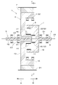
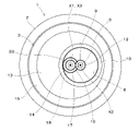
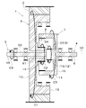
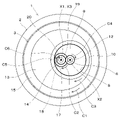
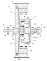
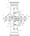
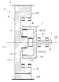
- FIG. 1 is a cross-sectional view taken along the line YY of FIG. 1 and is a diagram showing meshing of an internal gear portion, an external gear portion, a first external tooth, and a second external tooth. It is a figure which shows the operation when the rotary electric machine functions as a motor. It is a figure which shows the operation when the rotary electric machine functions as a motor. It is a figure which shows the operation when the rotary electric machine functions as a generator. It is a figure which shows the operation when the rotary electric machine functions as a generator. It is a figure explaining the power transmission when a rotary electric machine is used for a parallel hybrid type power transmission mechanism. It is sectional drawing which shows the modification example (the example which omitted the output shaft, etc.) of a rotary electric machine.
- the rotary electric machine 1 is a motor, a generator, a motor generator, or the like.
- 1 and 2 show an embodiment of the rotary electric machine 1 according to the present invention.
- the rotary electric machine 1 has a stator (stator) 2, a rotor (rotor) 3, an input member 4, and an output member 5.
- the rotary electric machine 1 is housed inside an accommodating body 24 such as a mission case or a motor casing, for example.
- the stator 2 has a cylindrical shape (cylindrical shape) and is non-rotatably housed inside the housing body 24.
- the stator 2 has, for example, a stator core and a coil.
- the rotor 3 is arranged on the inner peripheral side of the stator 2 and is rotatable.
- the rotor 3 has, for example, a rotor core and a permanent magnet.
- the direction of arrow A in FIG. 1 is referred to as forward
- the direction of arrow B is referred to as backward.
- the axis that is the center of rotation of the rotor 3 (hereinafter referred to as the rotation axis X1) extends in the front-rear direction.
- the input member 4 has an input shaft 6 and a power transmission unit 7.
- the input shaft 6 is a shaft for inputting rotational power to the rotor 3.
- the input shaft 6 extends in the front-rear direction.
- the input shaft 6 is rotatable around the axis X2.
- the axis X2 of the input shaft 6 is deviated from the direction in which the rotation axis X1 of the rotor 3 extends and does not match (see FIG. 2).
- the axis X2 of the input shaft 6 is not on the same axis as the direction in which the rotation axis X1 of the rotor 3 extends, but extends in parallel with the rotation axis X1.
- the outer peripheral surface of the input shaft 6 is supported by the first bearing 21.
- the first bearing 21 rotatably supports the input member 4 around the axis X2.
- the power transmission unit 7 is a portion that relays the transmission of power between the input shaft 6 and other members (rotor 3, output member 5).
- the power transmission unit 7 includes an internal gear unit 8 and an external gear unit 9.
- the power transmission unit 7 is integrally formed with the input shaft 6. Therefore, the internal gear portion 8 and the external gear portion 9 included in the power transmission unit 7 rotate around the axis X2 with the rotation of the input shaft 6.
- the power transmission unit 7 has a substrate 10, an outer protrusion 11, and a center protrusion 12.
- the substrate 10 has a disk shape, and one end of the input shaft 6 is connected to the center thereof.
- the input shaft 6 extends from the center of the substrate 10 to the side opposite to the rotor 3 side (rearward).
- the outer protruding portion 11 has a cylindrical shape and protrudes from the outer peripheral edge of the substrate 10 toward the rotor 3 side (front).
- the internal gear portion 8 is formed on the inner peripheral side of the outer protruding portion 11.
- the central projecting portion 12 projects from the center of the substrate 10 toward the rotor 3 side (front).
- An external gear portion 9 is formed on the outer peripheral side of the central protrusion portion 12.
- the central protruding portion 12 is located on the inner peripheral side of the outer protruding portion 11, and the external gear portion 9 is arranged on the inner peripheral side of the internal gear portion 8.
- the central protruding portion 12 and the external gear portion 9 do not appear overlapping with the gear portion 19 and the second external tooth 20, which will be described later, and are located on the back side of the paper surface of the gear portion 19 and the second external tooth 20. positioned.
- the amount of protrusion of the outer protrusion 11 from the substrate 10 is larger than the amount of protrusion of the central protrusion 12 from the substrate 10. Therefore, the external gear portion 9 and the internal gear portion 8 are located at positions deviated from each other in the axial center X2 direction of the input shaft 6. Specifically, the internal gear portion 8 is located at a position displaced forward from the external gear portion 9 in the axial center X2 direction of the input shaft 6.
- the rotor 3 has a base portion 13, a boss portion 14, and an outer ring portion 15.
- the base 13 is formed in a disk shape.
- the boss portion 14 has a cylindrical shape and protrudes from the center of the base portion 13 toward the input shaft 6 side (rearward).
- a through hole 16 is formed in the rotor 3.
- the through hole 16 penetrates the boss portion 14 and the base portion 13 in the front-rear direction.
- the center of the through hole 16 is located on the rotation axis X1 of the rotor 3.
- the rotor 3 has a first external tooth 17 that meshes with the internal gear portion 8.
- the first external tooth 17 is formed on the outer peripheral surface of the boss portion 14. That is, an external gear composed of the first external teeth 17 is formed on the outer peripheral surface of the boss portion 14.
- the first external tooth 17 is arranged on the inner peripheral side of the internal gear portion 8.
- the outer ring portion 15 is a cylindrical portion arranged on the outer peripheral side of the boss portion 14.
- the outer ring portion 15 projects from the outer peripheral edge of the base portion 13 toward the input shaft 6 side (rearward).
- the outer peripheral surface of the outer ring portion 15 is close to and faces the inner peripheral surface of the stator 2.
- the inner peripheral surface of the outer ring portion 15 is supported by the second bearing 22.
- the second bearing 22 rotatably supports the rotor 3 around the rotation axis X1.
- the second bearing 22 is arranged between the outer ring portion 15 and the power transmission portion 7. In other words, the second bearing 22 is arranged on the inner peripheral side of the outer ring portion 15 and on the outer peripheral side of the power transmission portion 7.
- An internal gear portion 8 is arranged between the boss portion 14 and the outer ring portion 15. That is, the boss portion 14 is arranged on the inner peripheral side of the inner gear portion 8, and the outer ring portion 15 is arranged on the outer peripheral side of the inner gear portion 8.
- the outer ring portion 15, the boss portion 14, and the outer protruding portion 11 are arranged so as to overlap each other in the front-rear direction.
- the outer protruding portion 11 and the boss portion 14 are arranged in a nested manner, and the outer ring portion 15 and the outer protruding portion 11 are arranged in a nested shape.
- the output member 5 has an output shaft 18 and a gear portion 19.
- the output shaft 18 is a shaft that takes out the rotational power output from the rotor 3.
- the output shaft 18 is rotatable around the axis X3.
- the output shaft 18 extends in the front-rear direction.
- the axis X3 of the output shaft 18 is on the same axis as the direction in which the rotation axis X1 of the rotor 3 extends.
- the output shaft 18 extends through the rotor 3. Specifically, the output shaft 18 is inserted through a through hole 16 formed in the rotor 3. A gap is provided between the outer peripheral surface of the output shaft 18 and the inner peripheral surface of the through hole 16.
- a gear portion 19 is provided at one end (rear end) of the output shaft 18.
- the output shaft 18 extends from the gear portion 19 toward the opposite side (forward) of the input shaft 6.
- the gear portion 19 has a second external tooth 20 that meshes with the external gear portion 9.
- the second external tooth 20 is arranged on the inner peripheral side of the internal gear portion 8.
- the direction in which the axis X3 of the output shaft 18 extends is not on the same axis as the direction in which the axis X2 of the input shaft 6 extends, and is parallel to the direction in which the axis X2 extends.
- the outer peripheral surface of the output shaft 18 is supported by the third bearing 23.
- the third bearing 23 rotatably supports the output member 5 including the output shaft 18 around the axis X3.
- the rotary electric machine 1 of the above-described embodiment has an input shaft 6 (input member 4) and an output shaft 18 (output member 5), whereas the rotary electric machine 1 according to the present invention has an input shaft 6 (input member 4).
- the output shaft 18 (output member 5) may be provided (see FIG. 8).
- the rotary electric machine 1 having no output shaft 18 can be used as a generator.
- the rotary electric machine 1 having no output shaft 18 will be described in more detail later.
- the rotary electric machine 1 can be installed inside a mission case or a motor casing.
- the mission oil or hydraulic fluid supplied to the inside of the mission case or the motor casing can be supplied to the rotary electric machine 1.
- the gears of the rotary electric machine 1 (external gear portion 9, internal gear portion 8, first external tooth 17, second external tooth 20) are supplied by the mission oil or hydraulic hydraulic oil supplied to the inside of the transmission case or the motor casing. It is possible to perform lubrication and cooling of the rotary electric machine 1. As a result, it is not necessary to newly provide a structure for lubrication and cooling of the rotary electric machine 1 separately from the structure for supplying the transmission oil or the hydraulic fluid.
- the rotary electric machine 1 functions as a motor in which the rotor 3 rotates around the rotation shaft X1 by passing an electric current through the coil of the stator 2. In this case, the rotational power of the rotor 3 is taken out from the output shaft 18.
- the boss portion 14 rotates in the same manner (see arrow C2), and the first outer shape formed on the boss portion 14 is formed.
- the internal gear portion 8 that meshes with the teeth 17 rotates (see arrow C3).
- the input member 4 rotates, so that the external gear portion 9 also rotates (see arrow C4).
- the rotary electric machine 1 can function as a motor for driving the driven machine connected to the output shaft 18.
- the rotary electric machine 1 functions as a generator that generates an electromotive force in the coil of the stator 2 by rotating the rotor 3 around the rotation axis X1 on the inner peripheral side of the stator 2.
- rotational power is input from the input shaft 6 to the rotor 3.
- the internal gear portion 8 rotates (see arrow D2), and a first external tooth 17 that meshes with the internal gear portion 8 is formed.
- the boss portion 14 rotates (see arrow D3).
- the boss portion 14 rotates, the rotor 3 rotates (see arrow D4), and an electromotive force is generated in the coil of the stator 2.
- the generated electromotive force is taken out from the conductor connected to the coil and stored in, for example, a battery. In this way, the rotary electric machine 1 can function as a generator that generates an electromotive force.
- the rotational power of the input shaft 6 is transmitted by the meshing between the internal gear portion 8 of the input member 4 and the first external tooth 17 of the rotor 3. Therefore, the rotation of the rotor 3 can be made faster than the rotation of the input shaft 6. Therefore, it is possible to obtain an output with a high rotation speed while downsizing the rotary electric machine 1. Further, since the amount of current is reduced and the heat generation is reduced by increasing the speed, the efficiency of the rotary electric machine 1 can be improved, and the cooling device for cooling the rotary electric machine 1 can be miniaturized.
- the rotary electric machine 1 can be made to function as a motor, a generator, or a motor generator.
- the rotary electric machine 1 When the rotary electric machine 1 functions as a motor generator, it can be used for a parallel hybrid type power transmission mechanism.
- the input shaft 6 is rotated by the power of a prime mover such as an engine.
- the external gear portion 9 rotates, and the gear portion 19 on which the second external tooth 20 that meshes with the external gear portion 9 is formed rotates.
- the output shaft 18 also rotates due to the rotation of the gear portion 19.
- a driven machine for example, a hydraulic pump or the like
- the internal gear portion 8 rotates, and the boss portion 14 on which the first external tooth 17 that meshes with the internal gear portion 8 is formed rotates.
- the boss portion 14 rotates, the rotor 3 rotates and an electromotive force is generated in the coil of the stator 2.
- the electric power generated by the electromotive force generated in the coil is stored in the battery.
- the rotor 3 is rotated, and the rotational power of the rotor 3 is transmitted from the first outer tooth 17 to the internal gear portion 8 to be inside.
- the external gear portion 9 rotates together with the gear portion 8.
- the second external tooth 20 rotates and the output shaft 18 rotates. That is, as shown in FIG. 7, the output shaft 18 is rotated by the power E1 of the prime mover and the rotational power E2 of the rotor 3 input via the input shaft 4.
- the rotational power E2 of the rotor 3 can assist the power E1 transmitted from the prime mover to the driven machine via the output shaft 18.
- the rotary electric machine 1 When the rotary electric machine 1 is used for the parallel hybrid type power transmission mechanism in this way, since the input shaft 6 and the output shaft 18 extend in the front-rear direction in parallel, the configuration is almost in-line, and the input to the rotary electric machine 1 and the input to the rotary electric machine 1 and The output becomes easy, and the rotary electric machine 1 can be compactly configured.
- the rotary electric machine 1 When the rotary electric machine 1 functions as a generator, it can also be used for a series hybrid type power transmission mechanism. In this case, the input shaft 6 is rotated by the power of an engine or the like. When the input shaft 6 rotates, the rotor 3 rotates by the same operation (action) as in the case of the parallel hybrid type power transmission mechanism described above, and an electromotive force is generated in the coil of the stator 2.
- the electric power generated by the electromotive force generated in the coil is stored in the battery.
- the electric power stored in the battery is used to drive a motor provided separately from the rotary electric machine 1, and the driven machine (for example, a hydraulic pump or the like) is driven by the drive of the motor.
- the rotary electric machine 1 when the rotary electric machine 1 is used for the series hybrid type power transmission mechanism, the rotary electric machine 1 only needs to function as a generator without functioning as a motor, so that the output shaft 18 becomes unnecessary. Therefore, as shown in FIG. 8, the rotary electric machine 1 has an output member 5 including an output shaft 18, a third bearing 23, a gear portion 19 having a second outer tooth 20, and a through hole 16 from the configuration shown in FIG. Can be omitted. Thereby, the rotary electric machine 1 can be configured more compactly. In particular, by omitting the output shaft 18, the length of the rotary electric machine 1 in the front-rear direction can be shortened, which greatly contributes to compactification. Further, by omitting the output shaft 18 and the like, there is an advantage that the number of parts of the rotary electric machine 1 can be reduced and the man-hours for assembling can be reduced.
- the rotary electric machine 1 includes a stator 2, a rotatable rotor 3 arranged on the inner peripheral side of the stator 2, and an input member 4 including an input shaft 6 for inputting rotational power to the rotor 3, and the input member 4 Has an internal gear portion 8 that rotates with the rotation of the input shaft 6, and the rotor 3 has a first external tooth 17 that meshes with the internal gear portion 8.
- the rotary electric machine 1 which can realize compactification and high efficiency with a simple structure. Specifically, when the rotational power is input from the input shaft 6 to the rotor 3, the rotational power of the input shaft 6 is transmitted by the meshing between the internal gear portion 8 and the first external tooth 17 of the rotor 3, so that the input shaft 6 has The rotation of the rotor 3 can be made faster than the rotation. Therefore, it is possible to obtain an output with a high rotation speed while downsizing the rotary electric machine 1. Further, since the amount of current is reduced and the heat generation is reduced by increasing the speed, the efficiency of the rotary electric machine 1 can be improved, and the cooling device for cooling the rotary electric machine 1 can be miniaturized. As a result, it becomes possible to realize compactness and high efficiency of the power transmission mechanism using a rotary electric machine such as a hybrid power transmission mechanism.
- the rotary electric machine 1 includes an output member 5 including an output shaft 18 for extracting rotational power output from the rotor 3, and the input member 4 has an external gear portion 9 that rotates with the rotation of the input shaft 6.
- the output member 5 has a second external tooth 20 that meshes with the external gear portion 9. According to this configuration, the rotor 3 is rotated by the rotational power input from the input member 4, and the rotational power of the rotor 3 can be taken out from the output shaft 18 of the output member 5. Therefore, the rotary electric machine 1 is used as a motor generator. It can be made to function and can be used in a parallel hybrid power transmission mechanism to realize compactness and high efficiency of the mechanism.
- first external tooth 17, the second external tooth 20, and the external gear portion 9 are arranged on the inner peripheral side of the internal gear portion 8. According to this configuration, the first external tooth 17, the second external tooth 20, and the external gear portion 9 are built in the inner peripheral side of the internal gear portion 8, so that the rotating shaft of the rotor 3 of the rotary electric machine 1 is formed.
- the length in the direction (length in the front-rear direction) can be shortened, and the rotary electric machine 1 can be made compact.
- the rotor 3 has a disk-shaped base portion 13, a boss portion 14 having a first outer tooth 17, and an annular outer ring portion 15 arranged on the outer peripheral side of the boss portion 14, and has a boss portion.
- the outer ring portion 14 and the outer ring portion 15 project from the base portion 13 toward the input shaft 6, and the inner gear portion 8 is arranged between the boss portion 14 and the outer ring portion 15.
- the boss portion 14 and the outer ring portion 15 are built in the inner peripheral side of the inner gear portion 8, the length of the rotor 3 of the rotary electric machine 1 in the rotation axis direction (length in the front-rear direction). The) can be shortened, and the rotary electric machine 1 can be made compact.
- the input member 4 has an input shaft 6 and a power transmission unit 7, the power transmission unit 7 has a substrate 10, an outer protrusion 11 and a center protrusion 12, and one end of the input shaft 6 is at the center of the substrate 10.
- the outer protruding portion 11 is cylindrical and protrudes from the outer peripheral edge of the substrate 10 toward the rotor 3 side
- the internal gear portion 8 is formed on the inner peripheral side
- the central protruding portion 12 is the substrate.
- the outer gear portion 9 is formed on the outer peripheral side from the center of the 10 toward the rotor 3, the outer protruding portion 11 and the boss portion 14 are arranged in a nested manner, and the outer ring portion 15 and the outer protruding portion 11 are It is arranged in a nested manner.
- the outer protruding portion 11 and the boss portion 14 are arranged in a nested manner, and the outer ring portion 15 and the outer protruding portion 11 are arranged in a nested manner, so that a simple structure that does not require a complicated structure is required.
- the length (length in the front-rear direction) of the rotor 3 of the rotary electric machine 1 in the rotation axis direction can be shortened, and the rotary electric machine 1 can be made compact.
- the output shaft 18 extends through the rotor 3.
- the axis X3 of the output shaft 18 can be arranged on the same axis as the rotary shaft X1 of the rotor 3, the diameter of the rotary electric machine 1 can be reduced and the rotary electric machine 1 can be made compact. It becomes possible to do. Further, the direction in which the axis X2 of the input shaft 6 extends is not on the same axis as the direction in which the axis X3 of the output shaft 18 extends, but is parallel.
- the input and output to the rotary electric machine 1 can be facilitated, and the rotary electric machine 1 can be compactly configured.
- the rotary electric machine 1 has a bearing (first bearing 21) that rotatably supports the rotor 3, and the bearing (first bearing 21) supports the inner peripheral surface of the outer ring portion 15. According to this configuration, since the bearing (first bearing 21) can be arranged inside the rotary electric machine 1, the rotary electric machine 1 can be compactly configured.
Landscapes
- Engineering & Computer Science (AREA)
- Power Engineering (AREA)
- Chemical & Material Sciences (AREA)
- Combustion & Propulsion (AREA)
- Transportation (AREA)
- Mechanical Engineering (AREA)
- Connection Of Motors, Electrical Generators, Mechanical Devices, And The Like (AREA)
- Gear Transmission (AREA)
Abstract
回転電機(1)は、ステータ(2)と、前記ステータ(2)の内周側に配置された回転可能なロータ(3)と、前記ロータ(3)に回転動力を入力する入力軸(6)を含む入力部材(4)と、を備え、前記入力部材(4)は、前記入力軸(6)の回転に伴って回転する内歯車部(8)を有し、前記ロータ(3)は、前記内歯車部(8)と噛み合う第1外歯(17)を有している。好ましくは、ロータ(3)から出力される回転動力を取り出す出力軸(18)を含む出力部材(5)を備え、前記入力部材(4)は、前記入力軸(6)の回転に伴って回転する外歯車部(9)を有し、前記出力部材(5)は、前記外歯車部(9)と噛み合う第2外歯(20)を有している。
Description
本発明は、モータ、ジェネレータ、モータ・ジェネレータ等の回転電機に関する。
従来、特許文献1に開示された回転電機を用いたハイブリッド式動力伝達機構が知られている。この動力伝達機構は、エンジン、回転電機(モータ・ジェネレータ)、被動機の順に接続された構造を有するパラレルハイブリッド式の動力伝達機構である。
上記したような回転電機を用いた動力伝達機構における構成機器間の接続は、直結方式が一般的であるため、動力伝達機構の構成機器の回転数は同一となる。そのため、回転電機の回転数はエンジン回転数と同じとなり、電流量等を考慮すれば効率の点で改善の余地がある。回転電機の回転数をエンジン回転数以上に高速化するための方法として、直結方式に代えてギアを介して接続する構造等を採用することが考えられる。しかし、ギアを用いた構造を採用する場合、遊星ギアを用いると構造が複雑となり、多段ギアを用いると大型化するという問題がある。
本発明は、上記問題を解決すべくなされたものであって、簡易な構造でコンパクト化と高効率化を実現できる回転電機を提供することを目的とする。
本発明が上記課題を解決するために講じた技術的手段は、以下に示す点を特徴とする。
回転電機は、ステータと、前記ステータの内周側に配置された回転可能なロータと、前記ロータに回転動力を入力する入力軸を含む入力部材と、を備え、前記入力部材は、前記入力軸の回転に伴って回転する内歯車部を有し、前記ロータは、前記内歯車部と噛み合う第1外歯を有している。
回転電機は、ステータと、前記ステータの内周側に配置された回転可能なロータと、前記ロータに回転動力を入力する入力軸を含む入力部材と、を備え、前記入力部材は、前記入力軸の回転に伴って回転する内歯車部を有し、前記ロータは、前記内歯車部と噛み合う第1外歯を有している。
好ましくは、回転電機は、前記ロータから出力される回転動力を取り出す出力軸を含む出力部材を備え、前記入力部材は、前記入力軸の回転に伴って回転する外歯車部を有し、前記出力部材は、前記外歯車部と噛み合う第2外歯を有している。
好ましくは、前記第1外歯、前記第2外歯及び前記外歯車部は、前記内歯車部の内周側に配置されている。
好ましくは、前記第1外歯、前記第2外歯及び前記外歯車部は、前記内歯車部の内周側に配置されている。
好ましくは、前記ロータは、円板状の基部と、前記第1外歯を有するボス部と、前記ボス部の外周側に配置された環状の外環部と、を有し、前記ボス部及び前記外環部は、前記基部から前記入力軸側に突出し、前記内歯車部は、前記ボス部と前記外環部との間に配置されている。
好ましくは、前記入力部材は、前記入力軸と動力伝達部を有し、前記動力伝達部は、基板と外側突出部と中心突出部を有し、前記基板の中心には、前記入力軸の一端部が接続され、前記外側突出部は、円筒形であって、前記基板の外周縁から前記ロータ側に向けて突出し、内周側に前記内歯車部が形成され、前記中心突出部は、前記基板の中心から前記ロータ側に向けて突出し、外周側に前記外歯車部が形成され、前記外側突出部と前記ボス部とは入れ子状に配置され、前記外環部と前記外側突出部とは入れ子状に配置されている。
好ましくは、前記入力部材は、前記入力軸と動力伝達部を有し、前記動力伝達部は、基板と外側突出部と中心突出部を有し、前記基板の中心には、前記入力軸の一端部が接続され、前記外側突出部は、円筒形であって、前記基板の外周縁から前記ロータ側に向けて突出し、内周側に前記内歯車部が形成され、前記中心突出部は、前記基板の中心から前記ロータ側に向けて突出し、外周側に前記外歯車部が形成され、前記外側突出部と前記ボス部とは入れ子状に配置され、前記外環部と前記外側突出部とは入れ子状に配置されている。
好ましくは、前記出力軸は、前記ロータを貫通して延びている。
好ましくは、前記入力軸の軸心が延びる方向は、前記出力軸の軸心が延びる方向と同一軸線上になく平行である。
好ましくは、回転電機は、前記ロータを回転可能に支持する軸受を有し、前記軸受は、前記外環部の内周面を支持している。
好ましくは、前記入力軸の軸心が延びる方向は、前記出力軸の軸心が延びる方向と同一軸線上になく平行である。
好ましくは、回転電機は、前記ロータを回転可能に支持する軸受を有し、前記軸受は、前記外環部の内周面を支持している。
本発明によれば、簡易な構造でコンパクト化と高効率化を実現できる回転電機を提供することができる。
以下、本発明に係る回転電機1の好適な実施形態について図面を参照しながら説明する。回転電機1は、モータ、ジェネレータ、モータ・ジェネレータ等である。
図1及び図2は、本発明に係る回転電機1の一実施形態を示している。
回転電機1は、ステータ(固定子)2、ロータ(回転子)3、入力部材4、出力部材5を有している。回転電機1は、例えば、ミッションケースやモータケーシング等の収容体24の内部に収容される。
図1及び図2は、本発明に係る回転電機1の一実施形態を示している。
回転電機1は、ステータ(固定子)2、ロータ(回転子)3、入力部材4、出力部材5を有している。回転電機1は、例えば、ミッションケースやモータケーシング等の収容体24の内部に収容される。
ステータ2は、筒状(円筒状)であって、収容体24の内部に回転不能に収容されている。ステータ2は、例えば、ステータコアとコイルとを有するものである。ロータ3は、ステータ2の内周側に配置されて回転可能である。ロータ3は、例えば、ロータコアと永久磁石を有するものである。
以下、説明の便宜上、図1の矢印A方向を前方、矢印B方向を後方という。ロータ3の回転中心となる軸(以下、回転軸X1という)は、前後方向に延びている。
以下、説明の便宜上、図1の矢印A方向を前方、矢印B方向を後方という。ロータ3の回転中心となる軸(以下、回転軸X1という)は、前後方向に延びている。
入力部材4は、入力軸6と動力伝達部7とを有している。
入力軸6は、ロータ3に回転動力を入力する軸である。入力軸6は、前後方向に延びている。入力軸6は、軸心X2回りに回転可能である。入力軸6の軸心X2は、ロータ3の回転軸X1が延びる方向とずれており一致していない(図2参照)。詳しくは、入力軸6の軸心X2は、ロータ3の回転軸X1が延びる方向と同一軸線上になく、回転軸X1と平行に延びている。入力軸6の外周面は、第1軸受21によって支持されている。第1軸受21は、入力部材4を軸心X2回りに回転可能に支持している。
入力軸6は、ロータ3に回転動力を入力する軸である。入力軸6は、前後方向に延びている。入力軸6は、軸心X2回りに回転可能である。入力軸6の軸心X2は、ロータ3の回転軸X1が延びる方向とずれており一致していない(図2参照)。詳しくは、入力軸6の軸心X2は、ロータ3の回転軸X1が延びる方向と同一軸線上になく、回転軸X1と平行に延びている。入力軸6の外周面は、第1軸受21によって支持されている。第1軸受21は、入力部材4を軸心X2回りに回転可能に支持している。
動力伝達部7は、入力軸6と他の部材(ロータ3、出力部材5)との間での動力の伝達を中継する部分である。動力伝達部7は、内歯車部8と外歯車部9とを含む。動力伝達部7は、入力軸6と一体に形成されている。そのため、動力伝達部7に含まれる内歯車部8及び外歯車部9は、入力軸6の回転に伴って軸心X2回りに回転する。
動力伝達部7は、基板10、外側突出部11、中心突出部12を有している。基板10は、円板状であって、中心に入力軸6の一端部が接続されている。入力軸6は、基板10の中心からロータ3側と反対側(後方)に延びている。外側突出部11は、円筒形であって、基板10の外周縁からロータ3側(前方)に向けて突出している。外側突出部11の内周側に内歯車部8が形成されている。中心突出部12は、基板10の中心からロータ3側(前方)に向けて突出している。中心突出部12の外周側に外歯車部9が形成されている。中心突出部12は外側突出部11の内周側に位置しており、外歯車部9は内歯車部8の内周側に配置されている。尚、図1において、中心突出部12及び外歯車部9は、後述する歯車部19及び第2外歯20と重なって表れておらず、歯車部19及び第2外歯20の紙面奥側に位置している。
動力伝達部7は、基板10、外側突出部11、中心突出部12を有している。基板10は、円板状であって、中心に入力軸6の一端部が接続されている。入力軸6は、基板10の中心からロータ3側と反対側(後方)に延びている。外側突出部11は、円筒形であって、基板10の外周縁からロータ3側(前方)に向けて突出している。外側突出部11の内周側に内歯車部8が形成されている。中心突出部12は、基板10の中心からロータ3側(前方)に向けて突出している。中心突出部12の外周側に外歯車部9が形成されている。中心突出部12は外側突出部11の内周側に位置しており、外歯車部9は内歯車部8の内周側に配置されている。尚、図1において、中心突出部12及び外歯車部9は、後述する歯車部19及び第2外歯20と重なって表れておらず、歯車部19及び第2外歯20の紙面奥側に位置している。
図1に示すように、外側突出部11の基板10からの突出量は、中心突出部12の基板10からの突出量より大きい。そのため、外歯車部9と内歯車部8とは、入力軸6の軸心X2方向においてずれた位置にある。具体的には、内歯車部8は、入力軸6の軸心X2方向において、外歯車部9よりも前方にずれた位置にある。
ロータ3は、基部13、ボス部14、外環部15を有している。
ロータ3は、基部13、ボス部14、外環部15を有している。
基部13は、円板状に形成されている。ボス部14は、円筒状であって、基部13の中心から入力軸6側(後方)に向けて突出している。ロータ3には、貫通孔16が形成されている。貫通孔16は、ボス部14及び基部13を前後方向に貫通している。貫通孔16の中心は、ロータ3の回転軸X1上に位置している。ロータ3は、内歯車部8と噛み合う第1外歯17を有している。第1外歯17は、ボス部14の外周面に形成されている。つまり、ボス部14の外周面には、第1外歯17からなる外歯車が形成されている。第1外歯17は、内歯車部8の内周側に配置されている。
外環部15は、ボス部14の外周側に配置された円筒状の部分である。外環部15は、基部13の外周縁から入力軸6側(後方)に向けて突出している。外環部15の外周面は、ステータ2の内周面と近接して対向している。外環部15の内周面は、第2軸受22によって支持されている。第2軸受22は、ロータ3を回転軸X1回りに回転可能に支持している。第2軸受22は、外環部15と動力伝達部7との間に配置されている。言い換えれば、第2軸受22は、外環部15の内周側であって動力伝達部7の外周側に配置されている。ボス部14と外環部15との間には、内歯車部8が配置されている。つまり、内歯車部8の内周側にボス部14が配置され、内歯車部8の外周側に外環部15が配置されている。
図1に示すように、外環部15とボス部14と外側突出部11とは、前後方向においてオーバーラップして配置されている。これにより、外側突出部11とボス部14とは入れ子状に配置され、外環部15と外側突出部11とは入れ子状に配置されている。
出力部材5は、出力軸18と歯車部19とを有している。出力軸18は、ロータ3から出力される回転動力を取り出す軸である。出力軸18は、軸心X3回りに回転可能である。出力軸18は、前後方向に延びている。出力軸18の軸心X3は、ロータ3の回転軸X1が延びる方向と同一軸線上にある。出力軸18は、ロータ3を貫通して延びている。詳しくは、出力軸18は、ロータ3に形成された貫通孔16に挿通されている。出力軸18の外周面と貫通孔16の内周面との間には、隙間が設けられている。
出力部材5は、出力軸18と歯車部19とを有している。出力軸18は、ロータ3から出力される回転動力を取り出す軸である。出力軸18は、軸心X3回りに回転可能である。出力軸18は、前後方向に延びている。出力軸18の軸心X3は、ロータ3の回転軸X1が延びる方向と同一軸線上にある。出力軸18は、ロータ3を貫通して延びている。詳しくは、出力軸18は、ロータ3に形成された貫通孔16に挿通されている。出力軸18の外周面と貫通孔16の内周面との間には、隙間が設けられている。
出力軸18の一端部(後端部)には、歯車部19が設けられている。出力軸18は、歯車部19から入力軸6と反対側(前方)に向けて延びている。歯車部19は、外歯車部9と噛み合う第2外歯20を有している。第2外歯20は、内歯車部8の内周側に配置されている。出力軸18の軸心X3が延びる方向は、入力軸6の軸心X2が延びる方向と同一軸線上になく、軸心X2が延びる方向と平行である。出力軸18の外周面は、第3軸受23によって支持されている。第3軸受23は、出力軸18を含む出力部材5を軸心X3回りに回転可能に支持している。
上述した実施形態の回転電機1は入力軸6(入力部材4)及び出力軸18(出力部材5)を有するものであるが、本発明に係る回転電機1は、入力軸6(入力部材4)を有するが出力軸18(出力部材5)を有さない構成としてもよい(図8参照)。出力軸18を有さない回転電機1は、ジェネレータとして使用することができる。出力軸18を有さない回転電機1については、後程、より詳しく説明する。
回転電機1は、ミッションケース又はモータケーシングの内部に設置することができる。これにより、ミッションケース又はモータケーシングの内部に供給されるミッションオイル又は油圧作動油を回転電機1に供給することができる。その結果、ミッションケース又はモータケーシングの内部に供給されるミッションオイル又は油圧作動油によって、回転電機1のギア(外歯車部9、内歯車部8、第1外歯17、第2外歯20)の潤滑と回転電機1の冷却とを行うことが可能となる。これにより、ミッションオイル又は油圧作動油の供給構造とは別に、回転電機1の潤滑や冷却のための構造を新たに設ける必要がない。
回転電機1は、ステータ2のコイルに電流を流すことによって、ロータ3が回転軸X1回りに回転するモータとして機能する。この場合、ロータ3の回転動力は、出力軸18から取り出される。図3、図4に示すように、ロータ3が回転軸X1回りに回転すると(矢印C1参照)、ボス部14が同様に回転し(矢印C2参照)、ボス部14に形成された第1外歯17と噛み合う内歯車部8が回転する(矢印C3参照)。内歯車部8が回転すると、入力部材4が回転するため、外歯車部9も回転する(矢印C4参照)。外歯車部9が回転すると、外歯車部9と噛み合う第2外歯20が回転し(矢印C5参照)、出力軸18が回転する(矢印C6参照)。出力軸18には油圧ポンプ等の被動機が接続されており、被動機は出力軸18の回転によって駆動する。このように、回転電機1は、出力軸18に接続された被動機を駆動するモータとして機能することができる。
回転電機1は、ステータ2の内周側にてロータ3が回転軸X1回りに回転することによって、ステータ2のコイルに起電力が発生するジェネレータとして機能する。この場合、入力軸6からロータ3に回転動力が入力される。図5、図6に示すように、入力軸6が回転すると(矢印D1参照)、内歯車部8が回転し(矢印D2参照)、内歯車部8と噛み合う第1外歯17が形成されたボス部14が回転する(矢印D3参照)。ボス部14が回転すると、ロータ3が回転し(矢印D4参照)、ステータ2のコイルに起電力が発生する。発生した起電力は、コイルと接続された導線から外部に取り出されて、例えばバッテリに貯蔵される。このように、回転電機1は、起電力を生じるジェネレータとして機能することができる。
回転電機1において、入力軸6からロータ3に回転動力が入力される場合、入力軸6の回転動力は入力部材4の内歯車部8とロータ3の第1外歯17との噛み合いによって伝達されるため、入力軸6の回転に比べてロータ3の回転を高速とすることができる。そのため、回転電機1を小型化しつつ高回転数の出力を得ることができる。また、高速化によって電流量が少なくなり発熱が減少するため、回転電機1を高効率化することができ、回転電機1を冷却するための冷却装置を小型化することもできる。
上述した通り、回転電機1は、モータとして機能させることもできるし、ジェネレータとして機能させることもできるし、モータ・ジェネレータとして機能させることもできる。
回転電機1は、モータ・ジェネレータとして機能させる場合、パラレルハイブリッド式の動力伝達機構に使用することができる。この場合、入力軸6はエンジン等の原動機の動力によって回転する。入力軸6が回転すると、外歯車部9が回転し、外歯車部9と噛み合う第2外歯20が形成された歯車部19が回転する。歯車部19の回転によって出力軸18も回転する。これによって、出力軸18に接続された被動機(例えば、油圧ポンプ等)が駆動する。また、入力軸6が回転すると、内歯車部8が回転し、内歯車部8と噛み合う第1外歯17が形成されたボス部14が回転する。ボス部14が回転すると、ロータ3が回転し、ステータ2のコイルに起電力が発生する。コイルに発生した起電力により生じた電力は、バッテリに蓄えられる。
回転電機1は、モータ・ジェネレータとして機能させる場合、パラレルハイブリッド式の動力伝達機構に使用することができる。この場合、入力軸6はエンジン等の原動機の動力によって回転する。入力軸6が回転すると、外歯車部9が回転し、外歯車部9と噛み合う第2外歯20が形成された歯車部19が回転する。歯車部19の回転によって出力軸18も回転する。これによって、出力軸18に接続された被動機(例えば、油圧ポンプ等)が駆動する。また、入力軸6が回転すると、内歯車部8が回転し、内歯車部8と噛み合う第1外歯17が形成されたボス部14が回転する。ボス部14が回転すると、ロータ3が回転し、ステータ2のコイルに起電力が発生する。コイルに発生した起電力により生じた電力は、バッテリに蓄えられる。
そして、原動機の駆動に加えて、バッテリに蓄えられた電力によって回転電機1を駆動すると、ロータ3が回転し、ロータ3の回転動力は第1外歯17から内歯車部8に伝達され、内歯車部8と共に外歯車部9が回転する。外歯車部9が回転すると、第2外歯20が回転し、出力軸18が回転する。つまり、図7に示すように、出力軸18は、入力軸4を介して入力される原動機の動力E1とロータ3の回転動力E2とによって回転する。言い換えれば、ロータ3の回転動力E2によって、原動機から出力軸18を介して被動機に伝達される動力E1をアシストすることができる。
このように回転電機1をパラレルハイブリッド式の動力伝達機構に使用する場合、入力軸6と出力軸18とが平行に前後方向に延びているため、ほぼインライン構成となり、回転電機1への入力及び出力が容易となるとともに、回転電機1をコンパクトに構成することができる。
回転電機1は、ジェネレータとして機能させる場合、シリーズハイブリッド式の動力伝達機構に使用することもできる。この場合、入力軸6はエンジン等の動力によって回転する。入力軸6が回転すると、上述したパラレルハイブリッド式の動力伝達機構の場合と同様の動作(作用)によって、ロータ3が回転し、ステータ2のコイルに起電力が発生する。コイルに発生した起電力により生じた電力は、バッテリに蓄えられる。バッテリに蓄えられた電力は、回転電機1とは別に設けられたモータの駆動に使用され、当該モータの駆動によって被動機(例えば、油圧ポンプ等)が駆動する。
回転電機1は、ジェネレータとして機能させる場合、シリーズハイブリッド式の動力伝達機構に使用することもできる。この場合、入力軸6はエンジン等の動力によって回転する。入力軸6が回転すると、上述したパラレルハイブリッド式の動力伝達機構の場合と同様の動作(作用)によって、ロータ3が回転し、ステータ2のコイルに起電力が発生する。コイルに発生した起電力により生じた電力は、バッテリに蓄えられる。バッテリに蓄えられた電力は、回転電機1とは別に設けられたモータの駆動に使用され、当該モータの駆動によって被動機(例えば、油圧ポンプ等)が駆動する。
このように、回転電機1をシリーズハイブリッド式の動力伝達機構に使用する場合、回転電機1をモータとして機能させることなくジェネレータとしてのみ機能させればよいため、出力軸18が不要となる。そのため、図8に示すように、回転電機1は、図1に示した構成から、出力軸18を含む出力部材5、第3軸受23、第2外歯20を有する歯車部19、貫通孔16を省略することができる。これにより、回転電機1を、よりコンパクトに構成することができる。特に、出力軸18を省略することで、回転電機1の前後方向の長さを短くできることがコンパクト化に大きく寄与する。また、出力軸18等を省略することによって、回転電機1の部品点数を減らして組み立ての工数を減少できるという利点もある。
上記実施形態の回転電機1によれば、以下の効果を奏することができる。
回転電機1は、ステータ2と、ステータ2の内周側に配置された回転可能なロータ3と、ロータ3に回転動力を入力する入力軸6を含む入力部材4と、を備え、入力部材4は、入力軸6の回転に伴って回転する内歯車部8を有し、ロータ3は、内歯車部8と噛み合う第1外歯17を有している。
回転電機1は、ステータ2と、ステータ2の内周側に配置された回転可能なロータ3と、ロータ3に回転動力を入力する入力軸6を含む入力部材4と、を備え、入力部材4は、入力軸6の回転に伴って回転する内歯車部8を有し、ロータ3は、内歯車部8と噛み合う第1外歯17を有している。
この構成によれば、簡易な構造でコンパクト化と高効率化を実現できる回転電機1を提供するができる。詳しくは、入力軸6からロータ3に回転動力を入力する場合、入力軸6の回転動力は内歯車部8とロータ3の第1外歯17との噛み合いにより伝達されるため、入力軸6の回転に比べてロータ3の回転を高速とすることができる。そのため、回転電機1を小型化しつつ高回転数の出力を得ることができる。また、高速化によって電流量が少なくなり発熱が減少するため、回転電機1を高効率化することができ、回転電機1を冷却するための冷却装置を小型化することもできる。その結果、ハイブリッド式動力伝達機構等の回転電機を用いた動力伝達機構のコンパクト化及び高効率化を実現可能となる。
また、回転電機1は、ロータ3から出力される回転動力を取り出す出力軸18を含む出力部材5を備え、入力部材4は、入力軸6の回転に伴って回転する外歯車部9を有し、出力部材5は、外歯車部9と噛み合う第2外歯20を有している。
この構成によれば、入力部材4から入力された回転動力によってロータ3を回転し、ロータ3の回転動力を出力部材5の出力軸18から取り出すことができるため、回転電機1をモータ・ジェネレータとして機能させることが可能となり、パラレルハイブリッド動力伝達機構に使用して、当該機構のコンパクト化及び高効率化を実現することができる。
この構成によれば、入力部材4から入力された回転動力によってロータ3を回転し、ロータ3の回転動力を出力部材5の出力軸18から取り出すことができるため、回転電機1をモータ・ジェネレータとして機能させることが可能となり、パラレルハイブリッド動力伝達機構に使用して、当該機構のコンパクト化及び高効率化を実現することができる。
また、第1外歯17、第2外歯20及び外歯車部9は、内歯車部8の内周側に配置されている。
この構成によれば、第1外歯17、第2外歯20及び外歯車部9が、内歯車部8の内周側に内蔵された構成となるため、回転電機1のロータ3の回転軸方向における長さ(前後方向の長さ)を短くすることができ、回転電機1をコンパクト化することが可能となる。
この構成によれば、第1外歯17、第2外歯20及び外歯車部9が、内歯車部8の内周側に内蔵された構成となるため、回転電機1のロータ3の回転軸方向における長さ(前後方向の長さ)を短くすることができ、回転電機1をコンパクト化することが可能となる。
また、ロータ3は、円板状の基部13と、第1外歯17を有するボス部14と、ボス部14の外周側に配置された環状の外環部15と、を有し、ボス部14及び外環部15は、基部13から入力軸6側に突出し、内歯車部8は、ボス部14と外環部15との間に配置されている。
この構成によれば、ボス部14及び外環部15が内歯車部8の内周側に内蔵された構成となるため、回転電機1のロータ3の回転軸方向における長さ(前後方向の長さ)を短くすることができ、回転電機1をコンパクト化することが可能となる。
この構成によれば、ボス部14及び外環部15が内歯車部8の内周側に内蔵された構成となるため、回転電機1のロータ3の回転軸方向における長さ(前後方向の長さ)を短くすることができ、回転電機1をコンパクト化することが可能となる。
また、入力部材4は入力軸6と動力伝達部7を有し、動力伝達部7は基板10と外側突出部11と中心突出部12を有し、基板10の中心には入力軸6の一端部が接続され、外側突出部11は、円筒形であって、基板10の外周縁からロータ3側に向けて突出し、内周側に内歯車部8が形成され、中心突出部12は、基板10の中心からロータ3側に向けて突出し、外周側に外歯車部9が形成され、外側突出部11とボス部14とは入れ子状に配置され、外環部15と外側突出部11とは入れ子状に配置されている。
この構成によれば、外側突出部11とボス部14とが入れ子状に配置され、外環部15と外側突出部11とが入れ子状に配置されることによって、複雑な構造を必要としない簡易な構成でありながら、回転電機1のロータ3の回転軸方向における長さ(前後方向の長さ)を短くすることができ、回転電機1をコンパクト化することが可能となる。
また、出力軸18は、ロータ3を貫通して延びている。
また、出力軸18は、ロータ3を貫通して延びている。
この構成によれば、出力軸18の軸心X3をロータ3の回転軸X1と同一軸線上に配置することができるため、回転電機1の直径を小さくすることができ、回転電機1をコンパクト化することが可能となる。
また、入力軸6の軸心X2が延びる方向は、出力軸18の軸心X3が延びる方向と同一軸線上になく平行である。
また、入力軸6の軸心X2が延びる方向は、出力軸18の軸心X3が延びる方向と同一軸線上になく平行である。
この構成によれば、回転電機1への入力及び出力が容易となるとともに、回転電機1をコンパクトに構成することができる。
また、回転電機1は、ロータ3を回転可能に支持する軸受(第1軸受21)を有し、軸受(第1軸受21)は外環部15の内周面を支持している。
この構成によれば、軸受(第1軸受21)を回転電機1の内部に配置することができるため、回転電機1をコンパクトに構成することができる。
また、回転電機1は、ロータ3を回転可能に支持する軸受(第1軸受21)を有し、軸受(第1軸受21)は外環部15の内周面を支持している。
この構成によれば、軸受(第1軸受21)を回転電機1の内部に配置することができるため、回転電機1をコンパクトに構成することができる。
以上、本発明の実施形態について説明したが、今回開示された実施の形態はすべての点で例示であって制限的なものではないと考えられるべきである。本発明の範囲は上記した説明ではなくて請求の範囲によって示され、請求の範囲と均等の意味及び範囲内での全ての変更が含まれることが意図される。
1 回転電機
2 ステータ
3 ロータ
4 入力部材
5 出力部材
6 入力軸
7 動力伝達部
8 内歯車部
9 外歯車部
10 基板
11 外側突出部
12 中心突出部
13 基部
14 ボス部
15 外環部
16 貫通孔
17 第1外歯
18 出力軸
19 歯車部
20 第2外歯
21 軸受(第1軸受)
X1 ロータの回転軸
X2 入力軸の軸心
X3 出力軸の軸心
2 ステータ
3 ロータ
4 入力部材
5 出力部材
6 入力軸
7 動力伝達部
8 内歯車部
9 外歯車部
10 基板
11 外側突出部
12 中心突出部
13 基部
14 ボス部
15 外環部
16 貫通孔
17 第1外歯
18 出力軸
19 歯車部
20 第2外歯
21 軸受(第1軸受)
X1 ロータの回転軸
X2 入力軸の軸心
X3 出力軸の軸心
Claims (8)
- ステータと、
前記ステータの内周側に配置された回転可能なロータと、
前記ロータに回転動力を入力する入力軸を含む入力部材と、
を備え、
前記入力部材は、前記入力軸の回転に伴って回転する内歯車部を有し、
前記ロータは、前記内歯車部と噛み合う第1外歯を有している回転電機。 - 前記ロータから出力される回転動力を取り出す出力軸を含む出力部材を備え、
前記入力部材は、前記入力軸の回転に伴って回転する外歯車部を有し、
前記出力部材は、前記外歯車部と噛み合う第2外歯を有している請求項1に記載の回転電機。 - 前記第1外歯、前記第2外歯及び前記外歯車部は、前記内歯車部の内周側に配置されている請求項2に記載の回転電機。
- 前記ロータは、円板状の基部と、前記第1外歯を有するボス部と、前記ボス部の外周側に配置された環状の外環部と、を有し、
前記ボス部及び前記外環部は、前記基部から前記入力軸側に突出し、
前記内歯車部は、前記ボス部と前記外環部との間に配置されている請求項1~3のいずれか1項に記載の回転電機。 - 前記入力部材は、前記入力軸と動力伝達部を有し、
前記動力伝達部は、基板と外側突出部と中心突出部を有し、
前記基板の中心には、前記入力軸の一端部が接続され、
前記外側突出部は、円筒形であって、前記基板の外周縁から前記ロータ側に向けて突出し、内周側に前記内歯車部が形成され、
前記中心突出部は、前記基板の中心から前記ロータ側に向けて突出し、外周側に前記外歯車部が形成され、
前記外側突出部と前記ボス部とは入れ子状に配置され、前記外環部と前記外側突出部とは入れ子状に配置されている請求項2を引用する請求項4に記載の回転電機。 - 前記出力軸は、前記ロータを貫通して延びている請求項2又は3に記載の回転電機。
- 前記入力軸の軸心が延びる方向は、前記出力軸の軸心が延びる方向と同一軸線上になく平行である請求項2,3,5のいずれか1項に記載の回転電機。
- 前記ロータを回転可能に支持する軸受を有し、
前記軸受は、前記外環部の内周面を支持している請求項4に記載の回転電機。
Priority Applications (3)
| Application Number | Priority Date | Filing Date | Title |
|---|---|---|---|
| EP21872236.1A EP4219979A4 (en) | 2020-09-25 | 2021-09-13 | ROTARY ELECTRIC MACHINE |
| JP2022551893A JP7483912B2 (ja) | 2020-09-25 | 2021-09-13 | 回転電機 |
| US18/121,661 US12323037B2 (en) | 2020-09-25 | 2023-03-15 | Rotating electrical machine |
Applications Claiming Priority (2)
| Application Number | Priority Date | Filing Date | Title |
|---|---|---|---|
| JP2020-161103 | 2020-09-25 | ||
| JP2020161103 | 2020-09-25 |
Related Child Applications (1)
| Application Number | Title | Priority Date | Filing Date |
|---|---|---|---|
| US18/121,661 Continuation US12323037B2 (en) | 2020-09-25 | 2023-03-15 | Rotating electrical machine |
Publications (1)
| Publication Number | Publication Date |
|---|---|
| WO2022065106A1 true WO2022065106A1 (ja) | 2022-03-31 |
Family
ID=80845360
Family Applications (1)
| Application Number | Title | Priority Date | Filing Date |
|---|---|---|---|
| PCT/JP2021/033528 Ceased WO2022065106A1 (ja) | 2020-09-25 | 2021-09-13 | 回転電機 |
Country Status (4)
| Country | Link |
|---|---|
| US (1) | US12323037B2 (ja) |
| EP (1) | EP4219979A4 (ja) |
| JP (1) | JP7483912B2 (ja) |
| WO (1) | WO2022065106A1 (ja) |
Citations (7)
| Publication number | Priority date | Publication date | Assignee | Title |
|---|---|---|---|---|
| JP2004122925A (ja) * | 2002-10-02 | 2004-04-22 | Kokusan Denki Co Ltd | ハイブリッド自動二輪車及びハイブリッド自動二輪車用動力伝達装置 |
| JP2007107717A (ja) * | 2005-09-14 | 2007-04-26 | Ntn Corp | 動力伝達装置および動力出力装置 |
| JP2007283892A (ja) * | 2006-04-17 | 2007-11-01 | Mitsubishi Electric Corp | 電動パワーステアリング装置および電動パワーステアリング装置用モータ |
| CN105743279A (zh) * | 2016-04-26 | 2016-07-06 | 苏州盛亿电机有限公司 | 电动自行车紧凑型中置电机 |
| JP2017040352A (ja) * | 2015-08-21 | 2017-02-23 | トヨタ自動車株式会社 | 車両用トランスアクスル構造 |
| JP2017105382A (ja) | 2015-12-11 | 2017-06-15 | 株式会社クボタ | パラレルハイブリッド動力伝達機構 |
| JP2019039551A (ja) * | 2017-08-29 | 2019-03-14 | 本田技研工業株式会社 | 車両駆動装置 |
Family Cites Families (6)
| Publication number | Priority date | Publication date | Assignee | Title |
|---|---|---|---|---|
| GB728804A (en) * | 1952-10-13 | 1955-04-27 | Gen Electric | Improvements in and relating to driving mechanism of the quill type |
| US8409042B2 (en) * | 2009-09-25 | 2013-04-02 | Tai-Her Yang | Externally rotating mechanism through offset outer rotating electrical machine drive |
| EP2946959B1 (de) * | 2014-05-21 | 2020-01-15 | Siegfried Muck | Hybrid-antriebseinheit sowie verfahren zum anlassen eines mit einer hybrid-antriebseinheit ausgerüsteten fahrzeuges |
| JP6624151B2 (ja) * | 2017-04-21 | 2019-12-25 | トヨタ自動車株式会社 | ハイブリッド四輪駆動車 |
| JP7025945B2 (ja) * | 2018-01-31 | 2022-02-25 | 株式会社小松製作所 | 電動機、回転駆動システム及び油圧ショベル |
| CN113644783B (zh) * | 2021-07-22 | 2023-05-02 | 广东金霸智能科技股份有限公司 | 驱动装置 |
-
2021
- 2021-09-13 JP JP2022551893A patent/JP7483912B2/ja active Active
- 2021-09-13 EP EP21872236.1A patent/EP4219979A4/en active Pending
- 2021-09-13 WO PCT/JP2021/033528 patent/WO2022065106A1/ja not_active Ceased
-
2023
- 2023-03-15 US US18/121,661 patent/US12323037B2/en active Active
Patent Citations (7)
| Publication number | Priority date | Publication date | Assignee | Title |
|---|---|---|---|---|
| JP2004122925A (ja) * | 2002-10-02 | 2004-04-22 | Kokusan Denki Co Ltd | ハイブリッド自動二輪車及びハイブリッド自動二輪車用動力伝達装置 |
| JP2007107717A (ja) * | 2005-09-14 | 2007-04-26 | Ntn Corp | 動力伝達装置および動力出力装置 |
| JP2007283892A (ja) * | 2006-04-17 | 2007-11-01 | Mitsubishi Electric Corp | 電動パワーステアリング装置および電動パワーステアリング装置用モータ |
| JP2017040352A (ja) * | 2015-08-21 | 2017-02-23 | トヨタ自動車株式会社 | 車両用トランスアクスル構造 |
| JP2017105382A (ja) | 2015-12-11 | 2017-06-15 | 株式会社クボタ | パラレルハイブリッド動力伝達機構 |
| CN105743279A (zh) * | 2016-04-26 | 2016-07-06 | 苏州盛亿电机有限公司 | 电动自行车紧凑型中置电机 |
| JP2019039551A (ja) * | 2017-08-29 | 2019-03-14 | 本田技研工業株式会社 | 車両駆動装置 |
Non-Patent Citations (1)
| Title |
|---|
| See also references of EP4219979A4 |
Also Published As
| Publication number | Publication date |
|---|---|
| US20230223817A1 (en) | 2023-07-13 |
| EP4219979A4 (en) | 2024-04-10 |
| JPWO2022065106A1 (ja) | 2022-03-31 |
| JP7483912B2 (ja) | 2024-05-15 |
| EP4219979A1 (en) | 2023-08-02 |
| US12323037B2 (en) | 2025-06-03 |
Similar Documents
| Publication | Publication Date | Title |
|---|---|---|
| US7211016B2 (en) | Geared motor with planetary gear assembly | |
| CN101495338B (zh) | 混合动力驱动装置 | |
| EP1317050B1 (en) | Hybrid farm tractor power train | |
| EP3482984A1 (en) | Power transmission device | |
| JP5110449B2 (ja) | 回転式アクチュエータ | |
| JP2020029959A (ja) | 減速装置及び電気機器 | |
| JP2000120810A (ja) | モータ組み込み減速機 | |
| WO2016180750A1 (en) | A marine vessel propulsion device, a pod unit and a marine vessel. | |
| US20220290749A1 (en) | Vehicle drive device | |
| CN116210138A (zh) | 车用驱动装置 | |
| WO2023182326A1 (ja) | 車両用駆動装置 | |
| CN116085430A (zh) | 一种轮毂电机齿轮减速机构及方法 | |
| CN118103617A (zh) | 车用驱动装置 | |
| WO2017145778A1 (ja) | 過給装置 | |
| JP4229765B2 (ja) | 風車ブレードのピッチ角制御装置 | |
| WO2022065106A1 (ja) | 回転電機 | |
| WO2017213035A1 (ja) | オイルポンプ | |
| CN110311508B (zh) | 旋转电机装置及具备旋转电机装置的车辆 | |
| CN110829715B (zh) | 一种可变磁场旋转电机 | |
| CN103032310A (zh) | 液压泵装置 | |
| JP2004147410A (ja) | 多層同軸回転電機およびそれを用いたハイブリッド駆動システム | |
| CN210693676U (zh) | 可变磁场旋转电机 | |
| CN214274368U (zh) | 一种内置齿差行星轮齿轮箱的电机 | |
| KR20230167555A (ko) | 인휠모터 장치 | |
| CN112728019A (zh) | 一种内置齿差行星轮齿轮箱的电机 |
Legal Events
| Date | Code | Title | Description |
|---|---|---|---|
| 121 | Ep: the epo has been informed by wipo that ep was designated in this application |
Ref document number: 21872236 Country of ref document: EP Kind code of ref document: A1 |
|
| ENP | Entry into the national phase |
Ref document number: 2022551893 Country of ref document: JP Kind code of ref document: A |
|
| NENP | Non-entry into the national phase |
Ref country code: DE |
|
| ENP | Entry into the national phase |
Ref document number: 2021872236 Country of ref document: EP Effective date: 20230425 |