WO2022065124A1 - 再生装置、再生装置の制御方法及びプログラム - Google Patents
再生装置、再生装置の制御方法及びプログラム Download PDFInfo
- Publication number
- WO2022065124A1 WO2022065124A1 PCT/JP2021/033650 JP2021033650W WO2022065124A1 WO 2022065124 A1 WO2022065124 A1 WO 2022065124A1 JP 2021033650 W JP2021033650 W JP 2021033650W WO 2022065124 A1 WO2022065124 A1 WO 2022065124A1
- Authority
- WO
- WIPO (PCT)
- Prior art keywords
- terminal device
- reproduction
- setting
- display device
- communication
- Prior art date
- Legal status (The legal status is an assumption and is not a legal conclusion. Google has not performed a legal analysis and makes no representation as to the accuracy of the status listed.)
- Ceased
Links
Images






Classifications
-
- H—ELECTRICITY
- H04—ELECTRIC COMMUNICATION TECHNIQUE
- H04N—PICTORIAL COMMUNICATION, e.g. TELEVISION
- H04N21/00—Selective content distribution, e.g. interactive television or video on demand [VOD]
- H04N21/40—Client devices specifically adapted for the reception of or interaction with content, e.g. set-top-box [STB]; Operations thereof
- H04N21/41—Structure of client; Structure of client peripherals
- H04N21/4104—Peripherals receiving signals from specially adapted client devices
- H04N21/4126—The peripheral being portable, e.g. PDAs or mobile phones
- H04N21/41265—The peripheral being portable, e.g. PDAs or mobile phones having a remote control device for bidirectional communication between the remote control device and client device
-
- H—ELECTRICITY
- H04—ELECTRIC COMMUNICATION TECHNIQUE
- H04N—PICTORIAL COMMUNICATION, e.g. TELEVISION
- H04N21/00—Selective content distribution, e.g. interactive television or video on demand [VOD]
- H04N21/40—Client devices specifically adapted for the reception of or interaction with content, e.g. set-top-box [STB]; Operations thereof
- H04N21/41—Structure of client; Structure of client peripherals
- H04N21/414—Specialised client platforms, e.g. receiver in car or embedded in a mobile appliance
- H04N21/41407—Specialised client platforms, e.g. receiver in car or embedded in a mobile appliance embedded in a portable device, e.g. video client on a mobile phone, PDA, laptop
-
- H—ELECTRICITY
- H04—ELECTRIC COMMUNICATION TECHNIQUE
- H04N—PICTORIAL COMMUNICATION, e.g. TELEVISION
- H04N21/00—Selective content distribution, e.g. interactive television or video on demand [VOD]
- H04N21/40—Client devices specifically adapted for the reception of or interaction with content, e.g. set-top-box [STB]; Operations thereof
- H04N21/43—Processing of content or additional data, e.g. demultiplexing additional data from a digital video stream; Elementary client operations, e.g. monitoring of home network or synchronising decoder's clock; Client middleware
- H04N21/436—Interfacing a local distribution network, e.g. communicating with another STB or one or more peripheral devices inside the home
- H04N21/43615—Interfacing a Home Network, e.g. for connecting the client to a plurality of peripherals
-
- H—ELECTRICITY
- H04—ELECTRIC COMMUNICATION TECHNIQUE
- H04N—PICTORIAL COMMUNICATION, e.g. TELEVISION
- H04N21/00—Selective content distribution, e.g. interactive television or video on demand [VOD]
- H04N21/40—Client devices specifically adapted for the reception of or interaction with content, e.g. set-top-box [STB]; Operations thereof
- H04N21/43—Processing of content or additional data, e.g. demultiplexing additional data from a digital video stream; Elementary client operations, e.g. monitoring of home network or synchronising decoder's clock; Client middleware
- H04N21/436—Interfacing a local distribution network, e.g. communicating with another STB or one or more peripheral devices inside the home
- H04N21/4363—Adapting the video stream to a specific local network, e.g. a Bluetooth® network
- H04N21/43637—Adapting the video stream to a specific local network, e.g. a Bluetooth® network involving a wireless protocol, e.g. Bluetooth®, RF or wireless LAN [IEEE 802.11]
-
- H—ELECTRICITY
- H04—ELECTRIC COMMUNICATION TECHNIQUE
- H04N—PICTORIAL COMMUNICATION, e.g. TELEVISION
- H04N21/00—Selective content distribution, e.g. interactive television or video on demand [VOD]
- H04N21/40—Client devices specifically adapted for the reception of or interaction with content, e.g. set-top-box [STB]; Operations thereof
- H04N21/43—Processing of content or additional data, e.g. demultiplexing additional data from a digital video stream; Elementary client operations, e.g. monitoring of home network or synchronising decoder's clock; Client middleware
- H04N21/442—Monitoring of processes or resources, e.g. detecting the failure of a recording device, monitoring the downstream bandwidth, the number of times a movie has been viewed, the storage space available from the internal hard disk
- H04N21/44227—Monitoring of local network, e.g. connection or bandwidth variations; Detecting new devices in the local network
-
- H—ELECTRICITY
- H04—ELECTRIC COMMUNICATION TECHNIQUE
- H04N—PICTORIAL COMMUNICATION, e.g. TELEVISION
- H04N21/00—Selective content distribution, e.g. interactive television or video on demand [VOD]
- H04N21/40—Client devices specifically adapted for the reception of or interaction with content, e.g. set-top-box [STB]; Operations thereof
- H04N21/45—Management operations performed by the client for facilitating the reception of or the interaction with the content or administrating data related to the end-user or to the client device itself, e.g. learning user preferences for recommending movies, resolving scheduling conflicts
- H04N21/4508—Management of client data or end-user data
- H04N21/4524—Management of client data or end-user data involving the geographical location of the client
-
- H—ELECTRICITY
- H04—ELECTRIC COMMUNICATION TECHNIQUE
- H04N—PICTORIAL COMMUNICATION, e.g. TELEVISION
- H04N21/00—Selective content distribution, e.g. interactive television or video on demand [VOD]
- H04N21/40—Client devices specifically adapted for the reception of or interaction with content, e.g. set-top-box [STB]; Operations thereof
- H04N21/47—End-user applications
- H04N21/485—End-user interface for client configuration
-
- H—ELECTRICITY
- H04—ELECTRIC COMMUNICATION TECHNIQUE
- H04N—PICTORIAL COMMUNICATION, e.g. TELEVISION
- H04N5/00—Details of television systems
- H04N5/76—Television signal recording
- H04N5/765—Interface circuits between an apparatus for recording and another apparatus
-
- G—PHYSICS
- G08—SIGNALLING
- G08C—TRANSMISSION SYSTEMS FOR MEASURED VALUES, CONTROL OR SIMILAR SIGNALS
- G08C2201/00—Transmission systems of control signals via wireless link
- G08C2201/90—Additional features
- G08C2201/93—Remote control using other portable devices, e.g. mobile phone, PDA, laptop
Definitions
- This disclosure relates to a reproduction device, a control method and a program of the reproduction device.
- a reproduction device that outputs a video signal to a display device is known (see, for example, Patent Document 1).
- this type of playback device it is necessary to make initial settings for the playback device when the power of the playback device is turned on for the first time after purchase.
- the display device is displayed with the initial setting screen output from the playback device in a state where the playback device and the display device are connected to each other via a cable.
- the remote controller of the playback device the user performs the initial setting of the playback device on the initial setting screen displayed on the display device.
- the present disclosure provides a reproduction device, a control method and a program of the reproduction device, which can make predetermined settings without using a display device.
- the reproduction device in the present disclosure is a reproduction device that can be connected to a display device and outputs a video signal to the display device.
- the first communication unit that establishes the communication with the external terminal device is established between the terminal device and the terminal device.
- a control unit for executing the first setting, which is a setting related to the reproduction device, is provided.
- predetermined settings can be made without using a display device.
- FIG. 1 is a conceptual diagram showing a system according to an embodiment.
- FIG. 2 is a block diagram showing a functional configuration of the system according to the embodiment.
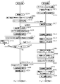
- FIG. 3 is a flowchart showing a flow of initial setting of the reproduction device according to the embodiment.
- FIG. 4 is a diagram showing an example of a screen displayed on the display device according to the embodiment.
- FIG. 5 is a sequence diagram showing a flow of network setting between the reproduction device and the terminal device according to the embodiment.
- FIG. 6 is a diagram showing an example of a screen displayed on the terminal device according to the embodiment.
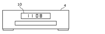
- FIG. 7 is a diagram showing an example of a password code displayed on the reproduction device according to the embodiment.
- FIG. 8 is a diagram showing an example of a screen displayed on the terminal device according to the embodiment.
- FIG. 1 is a conceptual diagram showing a system according to an embodiment.
- FIG. 2 is a block diagram showing a functional configuration of the system according to the embodiment.
- FIG. 3 is a flowchar
- FIG. 9 is a diagram showing an example of a screen displayed on the terminal device according to the embodiment.
- FIG. 10 is a diagram showing an example of a screen displayed on the terminal device according to the embodiment.
- FIG. 11 is a sequence diagram showing a flow of tuner reception settings between the reproduction device and the terminal device according to the embodiment.
- FIG. 12 is a diagram showing an example of a screen displayed on the terminal device according to the embodiment.
- FIG. 13 is a diagram showing an example of a screen displayed on the terminal device according to the embodiment.
- FIG. 14 is a sequence diagram showing a flow of network setting between the reproduction device and the terminal device according to the modified example of the embodiment.
- FIG. 1 is a conceptual diagram showing a system 2 according to an embodiment.
- the system 2 includes a reproduction device 4, a display device 6, and a terminal device 8.
- the playback device 4 reproduces video content recorded on an optical disk such as a BD (Blu-ray (registered trademark) Disc), DVD (Digital Versaille Disc), or an HDD (Hard Disc Drive), and plays a broadcast program. It is a BD / HDD recorder for recording.
- a front panel display unit 10 for displaying various information is arranged on the front surface of the reproduction device 4.
- the display device 6 is, for example, a liquid crystal television receiver for viewing a broadcast program, and is connected to the playback device 4 via a cable 12.
- the display device 6 has a display unit 14 for displaying video contents and the like reproduced by the reproduction device 4.
- the cable 12 is an HDMI (registered trademark) (High-Definition Multimedia Interface) cable.
- the terminal device 8 is a mobile terminal such as a smartphone or a tablet terminal.
- the terminal device 8 can wirelessly communicate with the playback device 4.
- An application for performing initial settings of the playback device 4 is installed in the terminal device 8. As will be described later, the user can perform the initial setting of the reproduction device 4 by using the terminal device 8 even when the display device 6 connected to the reproduction device 4 is in the power-off state.
- the initial settings are various settings (including network settings and tuner reception settings described later) that are performed when the power of the playback device 4 is turned on for the first time after the purchase of the playback device 4.
- FIG. 2 is a block diagram showing a functional configuration of the system 2 according to the embodiment.
- the reproduction device 4 has a tuner 16, a recording processing circuit 18, a reproduction processing circuit 20, a graphic module 22, a video signal processing circuit 24, and a front panel display unit 10 as functional configurations.
- Remote control light receiving unit 26 (example of reception unit), first communication module 28 (example of first communication unit), second communication module 30 (example of second communication unit), and wired LANI / It includes an F (Module Area Network Interface) 32, a USBI / F (Universal Serial Bus Interface) 34, a controller 36 (an example of a control unit), and an HDMI transmission unit 38 (an example of a detection unit).
- F Mode Area Network Interface
- USBI / F Universal Serial Bus Interface
- controller 36 an example of a control unit
- HDMI transmission unit 38 an example of a detection unit.
- the antenna 40 is arranged outside the reproduction device 4.
- the antenna 40 is connected to the tuner 16 and receives a broadcast wave (digital broadcast signal) transmitted from a broadcasting station.
- the broadcast wave includes, for example, radio waves for broadcasting terrestrial digital broadcasting, BS (Broadcasting Satellites) digital broadcasting, CS (Communication Satellites) digital broadcasting, and the like.
- the tuner 16 receives a broadcast program (digital broadcast program) included in the broadcast wave from the antenna 40.
- the recording processing circuit 18 performs processing for recording the broadcast program received by the tuner 16 on the recording medium 42.
- the recording medium 42 is, for example, an optical disk such as a BD or DVD inserted in the playback device 4, or an HDD built in the playback device 4.
- the reproduction processing circuit 20 performs processing for reproducing video contents such as broadcast programs recorded on the recording medium 42.
- the graphic module 22 generates various screens for display on the display device 6.
- the video signal processing circuit 24 generates a video signal and an audio signal indicating the video content reproduced by the reproduction processing circuit 20, and outputs the generated video signal and the audio signal to the HDMI transmission unit 38. Further, the video signal processing circuit 24 generates video signals indicating various screens generated by the graphic module 22, and outputs the generated video signals to the HDMI transmission unit 38.
- the front panel display unit 10 is a liquid crystal display for displaying various information.
- the remote control light receiving unit 26 receives an instruction input by the user through the remote control (not shown) of the playback device 4.
- the remote control light receiving unit 26 receives a remote control signal from the remote control and outputs the received remote control signal to the controller 36.
- the first communication module 28 is a communication module for communicating with the terminal device 8 by proximity wireless communication such as BLE (Bluetooth (registered trademark) Low Energy) or the like.
- BLE Bluetooth (registered trademark) Low Energy
- the second communication module 30 is a communication module for wireless communication with the wireless network 44 (an example of a network).
- the wireless network 44 is, for example, a wireless LAN compliant with the IEEE802.11 series, and is a 2.4 GHz band or 5 GHz band WiFi (registered trademark).
- the wireless network 44 is constructed by a wireless access point (AP) 46 connected to an internet line.
- the SSID (Service Set Identifier) of the wireless access point 46 is, for example, "abcd012", and the passcode is "xxxxyyy". Further, it is assumed that the terminal device 8 has established wireless communication with the wireless access point 46 and is connected to the wireless network 44.
- the wired LANI / F32 is a communication interface for connecting the playback device 4 and the wireless access point 46 to each other by wire.
- the wired LAN I / F 32 is connected to the wireless access point 46 via, for example, a wired network constructed by a wired LAN using an Ethernet (registered trademark) cable.
- the USBI / F34 is a communication interface for connecting the playback device 4 and a USB device (not shown) to each other.
- the controller 36 controls the operation of the reproduction device 4 based on the remote control signal from the remote control light receiving unit 26 and the control signal (described later) from the HDMI transmission unit 38. Specifically, the controller 36 executes, for example, various processes for initial setting of the reproduction device 4. Further, the controller 36 controls the display of various information on the front panel display unit 10. Further, the controller 36 instructs the graphic module 22 to generate various screens for display on the display device 6. Further, the controller 36 controls the first communication module 28 and the second communication module 30. Further, the controller 36 transmits / receives various data via the wired LANI / F32 and the USBI / F34.
- the HDMI transmission unit 38 is connected to the HDMI reception unit 50 of the display device 6 via a cable 12 (see FIG. 1).
- the HDMI transmission unit 38 transmits a video signal and an audio signal to the HDMI reception unit 50 of the display device 6 via a TMDS (Transition-Minimized Differential Signaling) channel via a cable 12. Further, the HDMI transmission unit 38 transmits and receives a control signal (CEC command) to and from the HDMI reception unit 50 of the display device 6 via the CEC (Consumer Electronics Control) channel via the cable 12.
- CEC command Control signal
- the HDMI standard stipulates a CEC for linking between multiple HDMI devices. According to CEC, CEC commands are transmitted in both directions between a plurality of HDMI devices. This communication is called CEC communication. By this CEC communication, the HDMI transmission unit 38 can detect, for example, the power state (power on state or power off state) of the display device 6 connected to the reproduction device 4.
- the display device 6 includes a display unit 14, a controller 48, and an HDMI receiving unit 50.
- the display unit 14 is a liquid crystal display panel for displaying various screens and the like.
- the controller 48 controls the operation of the display device 6 based on the control signal from the HDMI receiving unit 50. Further, the controller 48 controls the display of various screens and the like on the display unit 14.
- the HDMI receiving unit 50 receives a video signal and an audio signal from the HDMI transmitting unit 38 of the reproduction device 4 via the cable 12 via the TMDS channel. Further, the HDMI receiving unit 50 transmits and receives a control signal to and from the HDMI transmitting unit 38 of the reproduction device 4 via the cable 12 via the CEC channel.
- FIG. 3 is a flowchart showing a flow of initial setting of the reproduction device 4 according to the embodiment.
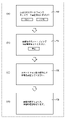
- FIG. 4 is a diagram showing an example of a screen displayed on the display device 6 according to the embodiment.
- the playback device 4 when the user turns on the power of the playback device 4 (S101), the playback device 4 outputs a grayout screen to the display device 6 (S102).
- This grayout screen is generated by the graphic module 22 and output to the display device 6 by the HDMI transmission unit 38.
- the HDMI transmission unit 38 detects the power supply state of the display device 6 based on the control signal from the display device 6 (S103).
- the power state of the display device 6 is the power off state (that is, when the HDMI transmitter 38 does not detect that the display device 6 is in the power on state) (“power off state” in S103)
- the first Communication module 28 transmits a beacon signal by BLE (S104). That is, the advertisement by BLE is started, and the first communication module 28 is in a state of waiting for a connection request from the terminal device 8 (S105).
- the beacon signal from the first communication module 28 is received by the terminal device 8 existing near the reproduction device 4.
- the terminal device 8 that has received the beacon signal transmits a connection request to the reproduction device 4.
- the first communication module 28 When the first communication module 28 receives the connection request from the terminal device 8 that has received the beacon signal (YES in S105), the first communication module 28 stops the transmission of the beacon signal (S106), and the terminal device that has received the beacon signal. Proximity wireless communication by BLE is started with 8 (S107). That is, proximity wireless communication between the first communication module 28 and the terminal device 8 is established.
- the controller 36 has a network setting (a first setting related to the reproduction device 4) which is a setting for connecting the reproduction device 4 to the wireless network 44 by the second communication module 30 with the terminal device 8. (Example)) is executed (S108).
- the second communication module 30 establishes wireless communication with the wireless access point 46 and is connected to the wireless network 44.
- the controller 36 executes the tuner reception setting (an example of the second setting) related to the setting of the tuner 16 with the terminal device 8 (S109). After the tuner reception setting is completed, the power of the playback device 4 is turned off (S110).
- step S105 when the user performs an operation for interrupting the transmission of the connection request to the playback device 4 by the terminal device 8 that has received the beacon signal (NO in S105, YES in S111). Will be explained.
- the terminal device 8 that has received the beacon signal transmits a suspension request to the reproduction device 4.
- the first communication module 28 stops the transmission of the beacon signal by receiving the interruption request from the terminal device 8 that has received the beacon signal (S112). After that, the power of the reproduction device 4 is turned off (S110).
- step S111 If the user does not perform an operation for interrupting the transmission of the connection request to the playback device 4 by the terminal device 8 that has received the beacon signal (NO in S111), the process returns to step S105 described above.
- the playback device 4 when the power state of the display device 6 is the power on state (“power on state” in S103), the playback device 4 outputs the initial setting start screen to the display device 6 (S113). ).
- This initial setting start screen is generated by the graphic module 22 and output to the display device 6 by the HDMI transmission unit 38.
- the user operates the remote controller of the reproduction device 4 to make various settings of the reproduction device 4 (S114).
- the various settings of the playback device 4 are, for example, a) settings related to the remote control of the playback device 4, b) settings related to the connection of the display device 6, and c) whether or not the display device 6 supports 4K / 60p. Includes confirmation settings, etc.
- the playback device 4 After completing various settings of the playback device 4, the playback device 4 outputs an inquiry screen 52 for inquiring the user whether or not to perform network settings using the terminal device 8 to the display device 6 (S115).
- the inquiry screen 52 is generated by the graphic module 22 and output to the display device 6 by the HDMI transmission unit 38.
- the display unit 14 of the display device 6 displays, for example, the inquiry screen 52 as shown in FIG. 4A.
- a message "Do you want to set up the network with your smartphone?" And a "Yes" button and a "No” button are displayed so that they can be selected and operated.
- the first The communication module 28 of 1 transmits a beacon signal by BLE (S117).
- the reproduction device 4 outputs a guidance screen 54 for prompting the user to perform an operation of the terminal device 8 (an operation for transmitting a connection request to the reproduction device 4) to the display device 6 (S118). ).
- the guidance screen 54 is generated by the graphic module 22 and output to the display device 6 by the HDMI transmission unit 38.
- the display unit 14 of the display device 6 displays, for example, the guidance screen 54 as shown in FIG. 4B.
- a message "Please make a connection request with your smartphone” and a "Cancel" button are displayed so that they can be selected and operated.
- step S105 advertisement by BLE is started, and the first communication module 28 is in a state of waiting for a connection request from the terminal device 8 (S105).
- step S105 advertisement by BLE is started, and the first communication module 28 is in a state of waiting for a connection request from the terminal device 8 (S105).
- step S105 advertisement by BLE is started, and the first communication module 28 is in a state of waiting for a connection request from the terminal device 8 (S105).
- step S111 the process of steps S105 to S112 is performed. If the process proceeds from step S105 to step S111 and the user selects and operates the "stop" button on the guidance screen 54 with the remote controller of the playback device 4, the process proceeds to step S112.
- the playback device 4 outputs a guidance screen 56 to the display device 6 to urge the user to operate the terminal device 8 to set the network setting and the tuner reception setting. do.
- the guidance screen 56 is generated by the graphic module 22 and output to the display device 6 by the HDMI transmission unit 38.
- the guidance screen 56 as shown in (c) of FIG. 4 is displayed on the display unit 14 of the display device 6, for example.
- the message "Please operate the smartphone to set the machine" is displayed.
- the playback device 4 outputs a notification screen 58 for notifying the user that the initial setting is completed to the display device 6.
- the notification screen 58 is generated by the graphic module 22 and output to the display device 6 by the HDMI transmission unit 38.
- the display unit 14 of the display device 6 displays, for example, the notification screen 58 as shown in FIG. 4D.
- the notification screen 58 for example, the message "The setting is completed. Turn off the power of this machine.” Is displayed.
- step S116 when the user selects and operates the "No" button on the inquiry screen 52 with the remote controller of the playback device 4, that is, when the user does not want to make network settings using the terminal device 8. (NO in S116), the user operates the remote controller of the playback device 4 to set the network on the screen displayed on the display device 6 (S119), and then set the tuner reception (S120). After that, the power of the reproduction device 4 is turned off (S110).
- FIG. 5 is a sequence diagram showing a flow of network setting between the reproduction device 4 and the terminal device 8 according to the embodiment.
- FIG. 6 is a diagram showing an example of a screen displayed on the terminal device 8 according to the embodiment.
- FIG. 7 is a diagram showing an example of a password code displayed on the reproduction device 4 according to the embodiment.
- 8 to 10 are diagrams showing an example of a screen displayed on the terminal device 8 according to the embodiment.
- the user activates the application installed in the terminal device 8 by operating the terminal device 8 (S201).
- the registration screen 60 is displayed on the terminal device 8 (S202).
- the "initial setting on smartphone” button is displayed so as to be selectable.
- the terminal device 8 is in a state of waiting for reception of the beacon signal from the playback device 4 (S203).
- the user turns on the power of the playback device 4 (S204).
- the reproduction device 4 Based on the control signal from the display device 6, the reproduction device 4 detects that the display device 6 is not in the power-on state (S205), and transmits a beacon signal by BLE (S206).
- the terminal device 8 receives the beacon signal from the playback device 4 and transmits a connection request to the playback device 4 (S207). If the terminal device 8 cannot receive the beacon signal from the playback device 4 even after a predetermined time has passed and the time-out occurs, for example, "Cannot connect. Please turn off the power of the recorder.” The message ".” Is displayed.
- the reproduction device 4 receives the connection request from the terminal device 8 that has received the beacon signal (S208), and stops the transmission of the beacon signal (S209). As a result, proximity wireless communication by BLE is established between the reproduction device 4 and the terminal device 8 (S210, S211).
- the playback device 4 displays the password code on the front panel display unit 10 (S212).
- the password code is a 4-digit number such as "1108".
- the password code input screen 62 is displayed on the terminal device 8.
- a message "Please enter the 4-digit number displayed on the front panel of the recorder” an input field for the password code, and an input key are displayed.
- the user inputs the password code displayed on the front panel display unit 10 of the playback device 4 on the password code input screen 62 (S213).
- the terminal device 8 transmits the input password code to the reproduction device 4 (S214).
- the reproduction device 4 receives the password code transmitted from the terminal device 8 and determines whether or not the received password code is correct (S215). If the password code is incorrect (NO in S215), the playback device 4 updates the password code (S216) and displays the updated new password code on the front panel display unit 10 (S212). The reproduction device 4 forcibly turns off the power supply when the received password code is incorrect a total of three times.
- the terminal device 8 requests the playback device 4 to transmit the AP (access point) list (S216).
- the reproduction device 4 executes an AP scan to generate an AP list, and transmits the generated AP list to the terminal device 8 (S217).
- the terminal device 8 receives the AP list from the playback device 4 (S218). At this time, as shown in FIG. 9, the terminal device 8 displays the AP list screen 64 based on the received AP list. On the AP list screen 64, for example, the message "Please select the same network as the smartphone.” And the SSIDs "abcd012", “bbef034", "ccgh056" and "bcde123" of the wireless access points detected by the AP scan are displayed. Is displayed.
- the user selects the SSID "abcd012" of the wireless access point 46 for which wireless communication has been established with the terminal device 8 on the AP list screen 64 (S219).
- the passcode input screen 66 is displayed on the terminal device 8.
- a message "Please enter the passcode of abcd012” a passcode input field, and a numeric keypad are displayed.
- the user inputs the passcode "xxxxyyy" of the SSID "abcd012" on the passcode input screen 66 (S219).
- the terminal device 8 transmits the SSID and the passcode input by the user to the playback device 4 (S220).
- the playback device 4 receives the SSID and passcode transmitted from the terminal device 8 (S221). As a result, the proximity wireless communication between the reproduction device 4 and the terminal device 8 is disconnected (S222, S223), and the reproduction device 4 performs wireless communication with the wireless access point 46 based on the received SSID and passcode. It is established (S224) and the connection with the wireless network 44 is started.
- the terminal device 8 searches for the reproduction device 4 via the wireless network 44 (S225), and connects to the reproduction device 4 via the wireless network 44 (S226). After that, the tuner reception setting is performed between the playback device 4 and the terminal device 8 as described later.
- FIG. 11 is a sequence diagram showing a flow of tuner reception settings between the reproduction device 4 and the terminal device 8 according to the embodiment.
- 12 and 13 are diagrams showing an example of a screen displayed on the terminal device 8 according to the embodiment.
- the playback device 4 When the playback device 4 can acquire the zip code information necessary for setting the tuner reception from the display device 6, the playback device 4 sets the tuner reception based on the zip code information acquired from the display device 6.
- the postal code information is information indicating the postal code of the area where the reproduction device 4 is installed.
- the terminal device 8 instructs the playback device 4 to acquire the zip code information via the wireless network 44 (S301).
- the reproduction device 4 attempts to acquire the zip code information from the display device 6 by CEC (S302), and notifies the terminal device 8 of the failure to acquire the zip code information via the wireless network 44 (S303).
- the terminal device 8 receives the notification from the playback device 4 (S304), and determines whether or not there is another existing playback device (not shown) for which the tuner reception setting has been executed (S305). If the existing playback device does not exist (NO in S305), the postal code input screen 68 is displayed on the terminal device 8 as shown in FIG. On the zip code input screen 68, for example, a message "Please enter your zip code in 7 digits", a zip code input field, and an input key are displayed. On the postal code input screen 68, the user inputs a postal code of his / her area of residence, for example, "571-8501" (S306). As a result, the terminal device 8 transmits the zip code information indicating the zip code input by the user to the reproduction device 4 (S307).
- the terminal device 8 acquires the postal code information from the existing playback device via the wireless network 44 (S308). As a result, the terminal device 8 transmits the zip code information indicating the zip code acquired from the existing playback device to the playback device 4 (S307).
- the playback device 4 receives the postal code information transmitted from the terminal device 8 (S309), and is in a state of waiting for a channel scan instruction (S310).
- the terminal device 8 instructs the playback device 4 to perform a channel scan via the wireless network 44 (S311)
- the playback device 4 sets the area from the received zip code information and starts the channel scan (S311). S312).
- the terminal device 8 is in the state of waiting for the completion of the channel scan (S313).
- the terminal device 8 displays a standby screen 70 indicating that the channel scan is waiting for completion.
- a progress bar indicating the progress of the channel scan is displayed together with the message "Channel is being set. Digital terrestrial channel is being scanned.”
- the playback device 4 transmits a completion notification to the terminal device 8 to notify that the channel scan is completed via the wireless network 44 (S314).
- the terminal device 8 receives the completion notification transmitted from the playback device 4 (S315). As described above, the tuner reception setting is completed.
- the reproduction device 4 is a reproduction device that can be connected to the display device 6 and outputs a video signal to the display device 6.
- the playback device 4 communicates with the HDMI transmission unit 38 that detects the power state of the display device 6 and the external terminal device 8 when the HDMI transmission unit 38 does not detect that the display device 6 is in the power-on state.
- the first setting which is the setting related to the reproduction device 4 is executed between the terminal device 8 and the terminal device 8.
- the controller 36 is provided.
- the terminal device 8 and the first communication module 28 establish communication with the terminal device 8 by establishing communication with the terminal device 8.
- the first setting can be performed in between. As a result, the first setting can be made without using the display device 6, and the convenience of the user can be enhanced.
- the first communication module 28 transmits a beacon signal to the terminal device 8 when the HDMI transmission unit 38 does not detect that the display device 6 is in the power-on state, and the beacon is used. Establish communication with the terminal device 8 that has received the signal.
- the playback device 4 further includes a remote control light receiving unit 26 that receives a user's instruction.
- the first communication module 28 is a case where the HDMI transmission unit 38 detects that the display device 6 is in the power-on state, and the remote control light receiving unit 26 makes the first setting using the terminal device 8.
- the beacon signal is transmitted to the terminal device 8 and the communication with the terminal device 8 that has received the beacon signal is established.
- the reproduction device 4 further includes a second communication module 30 for communicating with the wireless network 44.
- the first setting is a setting for connecting the reproduction device 4 to the wireless network 44 by the second communication module 30.
- the terminal device 8 can be used to execute the first setting for connecting the playback device 4 to the wireless network 44 by the second communication module 30.
- the wireless network 44 is a wireless LAN.
- the first communication module 28 receives the SSID of the wireless LAN wireless access point 46 input to the terminal device 8 by the user from the terminal device 8.
- the controller 36 executes the first setting based on the SSID received by the first communication module 28.
- the first setting can be executed based on the SSID input by the user to the terminal device 8.
- the reproduction device 4 further includes a tuner 16 for receiving broadcast waves.
- the second communication module 30 establishes communication with the terminal device 8 via the wireless network 44 when the reproduction device 4 is connected to the wireless network 44.
- the controller 36 can acquire the postal code information indicating the postal code of the area where the reproduction device 4 is installed from the display device 6, the controller 36 sets the second setting regarding the setting of the tuner 16 based on the acquired postal code information.
- the second communication module 30 is another reproduction in which the second setting has been executed for the terminal device 8 via the wireless network 44 when the controller 36 cannot acquire the zip code information from the display device 6. Instruct to get zip code information from the device.
- the terminal device 8 is made to acquire the zip code information from another playback device for which the second setting has been executed. Can be done.
- control method of the reproduction device 4 is a control method of the reproduction device 4 which can be connected to the display device 6 and outputs a video signal to the display device 6.
- the control method of the playback device 4 includes a step of detecting the power state of the display device 6 and a step of establishing communication with an external terminal device 8 when it is not detected that the display device 6 is in the power-on state. It includes a step of executing the first setting between the terminal device 8 and the terminal device 8 when the communication between the terminal device 8 and the playback device 4 is established.
- the first setting can be made without using the display device 6, and the convenience of the user can be enhanced.
- the program causes the computer to execute the control method of the reproduction device 4 described above.
- FIG. 14 is a sequence diagram showing a flow of network setting between the reproduction device 4 and the terminal device 8 according to the modified example of the embodiment.
- steps S216 to S219 described with reference to FIG. 5 are replaced with steps S401 and S402.
- step S215 the terminal device 8 requests the SSID and passcode from another existing playback device (not shown) that has executed the network setting via the wireless network 44 (S401), and the existing playback device 8 is used. Receive the SSID and passcode from the device (S402). After that, the terminal device 8 transmits the SSID and the passcode received from the existing playback device to the playback device 4 (S220).
- the wireless network 44 is a wireless LAN.
- the first communication module 28 receives the SSID of the wireless access point 46 of the wireless LAN acquired from the other playback device for which the terminal device 8 has executed the first setting from the terminal device 8.
- the controller 36 executes the first setting based on the SSID received by the first communication module 28.
- the terminal device 8 can execute the first setting based on the SSID acquired from another playback device for which the first setting has been executed. As a result, it is possible to omit the input of the SSID and the passcode by the user, and it is possible to improve the convenience of the user.
- the HDMI transmission unit 38 detects the power state of the display device 6, but when the display device 6 detects that the power is off, the display device 6 is not necessarily connected to the playback device 4. You don't have to be. That is, the HDMI transmission unit 38 cannot detect that the display device 6 is in the power-on state when the display device 6 is not connected to the playback device 4.
- the reproduction device 4 performs processing by the following algorithm. i) Check the HDMI connection status with the HDMI receiver 50 and the power-on status of the display device 6, ii) direct the input of the display device 6 to the playback device 4 with the CEC command, and ii) play the input with the CEC command. It is determined whether or not the display device 6 is suitable for the device 4, and whether or not the display device 6 is in the Active Source state is determined by the iv) CEC command.
- the reproduction device 4 is wirelessly connected to the wireless access point 46 by the second communication module 30, but the reproduction device 4 is not limited to this, and is connected to the wireless access point 46 by the wired LAN / IF 32. It may be connected by wire.
- the terminal device 8 may display an inquiry screen for asking the user whether to connect to the wireless access point 46 by a wireless LAN or a wired LAN.
- the controller 36 disables the wired LAN / IF 32 and enables the second communication module 30.
- each process after step S217 in the flowchart of FIG. 5 is executed.
- the controller 36 enables the wired LAN / IF 32 and disables the second communication module 30. In this case, each process after step S217 in the flowchart of FIG. 5 is not executed, the wired connection between the playback device 4 and the wireless access point 46 is established, and the proximity wireless connection between the playback device 4 and the terminal device 8 is disconnected. To.
- the proximity wireless communication by BLE is established between the reproduction device 4 and the terminal device 8, but instead of such a configuration, the reproduction device 4 and the terminal device 8 are used. USB communication may be established between them.
- the terminal device 8 is connected to the USB I / F 34 via the USB cable, and the authentication process using the above-mentioned password code becomes unnecessary.
- the proximity wireless communication by BLE is established between the reproduction device 4 and the terminal device 8, but instead of such a configuration, the reproduction device 4 is set to the master unit mode (AP). As a mode), information about the wireless access point 46 may be set from the terminal device 8 by directly communicating with the terminal device 8 (ad hoc communication). After that, the reproduction device 4 may be changed to the slave unit mode and connected to the wireless access point 46 by infrastructure communication.
- AP master unit mode
- each component may be configured by dedicated hardware or may be realized by executing a software program suitable for each component.
- Each component may be realized by a program execution unit such as a CPU or a processor reading and executing a software program recorded on a non-temporary recording medium such as a hard disk or a semiconductor memory.
- a part or all of the functions of the reproduction device 4 according to each of the above embodiments may be realized by executing a program by a processor such as a CPU.
- the playback device of the present disclosure can be applied as, for example, a BD recorder connected to a television receiver via a cable.
- Second communication module 32 Wired LAN I / F 34 USB I / F 36, 48 Controller 38 HDMI transmitter 40 Antenna 42 Recording medium 44 Wireless network 46 Wireless access point 50 HDMI receiver 52 Inquiry screen 54, 56 Guidance screen 58 Notification screen 60 Registration screen 62 Password code input screen 64 AP list screen 66 Passcode Input screen 68 Postal code input screen 70 Standby screen
Landscapes
- Engineering & Computer Science (AREA)
- Multimedia (AREA)
- Signal Processing (AREA)
- Computer Networks & Wireless Communication (AREA)
- Databases & Information Systems (AREA)
- Human Computer Interaction (AREA)
- General Engineering & Computer Science (AREA)
- Two-Way Televisions, Distribution Of Moving Picture Or The Like (AREA)
Abstract
Description
以下、図1~図14を参照しながら、実施の形態について説明する。
まず、図1を参照しながら、実施の形態に係るシステム2の概要について説明する。図1は、実施の形態に係るシステム2を示す概念図である。
図2を参照しながら、実施の形態に係るシステム2の機能構成について説明する。図2は、実施の形態に係るシステム2の機能構成を示すブロック図である。
図3及び図4を参照しながら、実施の形態に係る再生装置4の初期設定の流れについて説明する。図3は、実施の形態に係る再生装置4の初期設定の流れを示すフローチャートである。図4は、実施の形態に係る表示装置6に表示される画面の一例を示す図である。
図5~図10を参照しながら、再生装置4と端末装置8との間におけるネットワーク設定の流れについて具体的に説明する。図5は、実施の形態に係る再生装置4と端末装置8との間におけるネットワーク設定の流れを示すシーケンス図である。図6は、実施の形態に係る端末装置8に表示される画面の一例を示す図である。図7は、実施の形態に係る再生装置4に表示される暗証コードの一例を示す図である。図8~図10は、実施の形態に係る端末装置8に表示される画面の一例を示す図である。
図11~図13を参照しながら、再生装置4と端末装置8との間におけるチューナ受信設定の流れについて具体的に説明する。図11は、実施の形態に係る再生装置4と端末装置8との間におけるチューナ受信設定の流れを示すシーケンス図である。図12及び図13は、実施の形態に係る端末装置8に表示される画面の一例を示す図である。
上述したように、本実施の形態では、再生装置4は、表示装置6と接続可能であり、表示装置6に映像信号を出力する再生装置である。再生装置4は、表示装置6の電源状態を検出するHDMI送信部38と、HDMI送信部38により表示装置6が電源オン状態であることが検出されない場合に、外部の端末装置8との通信を確立する第1の通信モジュール28と、端末装置8と第1の通信モジュール28との通信が確立された際に、端末装置8との間で再生装置4に関する設定である第1の設定を実行するコントローラ36とを備える。
次に、図14を参照しながら、実施の形態の変形例に係る再生装置4と端末装置8との間におけるネットワーク設定の流れについて説明する。図14は、実施の形態の変形例に係る再生装置4と端末装置8との間におけるネットワーク設定の流れを示すシーケンス図である。
以上のように、本出願において開示する技術の例示として、上記実施の形態を説明した。しかしながら、本開示における技術は、これに限定されず、適宜、変更、置き換え、付加、省略などを行った実施の形態にも適用可能である。また、上記実施の形態で説明した各構成要素を組み合わせて、新たな実施の形態とすることも可能である。
4 再生装置
6 表示装置
8 端末装置
10 フロントパネル表示部
12 ケーブル
14 表示部
16 チューナ
18 記録処理回路
20 再生処理回路
22 グラフィックモジュール
24 映像信号処理回路
26 リモコン受光部
28 第1の通信モジュール
30 第2の通信モジュール
32 有線LANI/F
34 USBI/F
36,48 コントローラ
38 HDMI送信部
40 アンテナ
42 記録媒体
44 無線ネットワーク
46 無線アクセスポイント
50 HDMI受信部
52 問い合わせ画面
54,56 案内画面
58 通知画面
60 登録画面
62 暗証コード入力画面
64 APリスト画面
66 パスコード入力画面
68 郵便番号入力画面
70 待機画面
Claims (9)
- 表示装置と接続可能であり、前記表示装置に映像信号を出力する再生装置であって、
前記表示装置の電源状態を検出する検出部と、
前記検出部により前記表示装置が電源オン状態であることが検出されない場合に、外部の端末装置との通信を確立する第1の通信部と、
前記端末装置と前記第1の通信部との通信が確立された際に、前記端末装置との間で前記再生装置に関する設定である第1の設定を実行する制御部と、を備える
再生装置。 - 前記第1の通信部は、前記検出部により前記表示装置が電源オン状態であることが検出されない場合に、前記端末装置に対してビーコン信号を送信し、前記ビーコン信号を受信した前記端末装置との通信を確立する
請求項1に記載の再生装置。 - 前記再生装置は、さらに、ユーザの指示を受け付ける受付部を備え、
前記第1の通信部は、前記検出部により前記表示装置が電源オン状態であると検出された場合であって、前記受付部により前記端末装置を用いて前記第1の設定を行う旨の前記ユーザの指示が受け付けられた場合に、前記端末装置に対して前記ビーコン信号を送信し、前記ビーコン信号を受信した前記端末装置との通信を確立する
請求項2に記載の再生装置。 - 前記再生装置は、さらに、ネットワークと通信するための第2の通信部を備え、
前記第1の設定は、前記第2の通信部により前記再生装置を前記ネットワークに接続するための設定である
請求項1~3のいずれか1項に記載の再生装置。 - 前記ネットワークは、無線LAN(Local Area Network)であり、
前記第1の通信部は、ユーザが前記端末装置に入力した前記無線LANのアクセスポイントのSSID(Service Set Identifier)を前記端末装置から受信し、
前記制御部は、前記第1の通信部により受信された前記SSIDに基づいて、前記第1の設定を実行する
請求項4に記載の再生装置。 - 前記ネットワークは、無線LANであり、
前記第1の通信部は、前記端末装置が前記第1の設定を実行済みの他の再生装置から取得した前記無線LANの無線アクセスポイントのSSIDを前記端末装置から受信し、
前記制御部は、前記第1の通信部により受信された前記SSIDに基づいて、前記第1の設定を実行する
請求項4に記載の再生装置。 - 前記再生装置は、さらに、放送波を受信するチューナを備え、
前記第2の通信部は、前記再生装置が前記ネットワークに接続された際に、前記ネットワークを介して前記端末装置との通信を確立し、
前記制御部は、前記再生装置が設置された地域の郵便番号を示す郵便番号情報を前記表示装置から取得できた場合に、取得した前記郵便番号情報に基づいて、前記チューナの設定に関する第2の設定を実行し、
前記第2の通信部は、前記制御部が前記郵便番号情報を前記表示装置から取得できなかった場合に、前記ネットワークを介して、前記端末装置に対して前記第2の設定を実行済みの他の再生装置から前記郵便番号情報を取得するように指示する
請求項4~6のいずれか1項に記載の再生装置。 - 表示装置と接続可能であり、前記表示装置に映像信号を出力する再生装置の制御方法であって、
前記表示装置の電源状態を検出するステップと、
前記表示装置が電源オン状態であることが検出されない場合に、外部の端末装置との通信を確立するステップと、
前記端末装置と前記再生装置との通信が確立された際に、前記端末装置との間で第1の設定を実行するステップと、を含む
再生装置の制御方法。 - 請求項8に記載の再生装置の制御方法をコンピュータに実行させる
プログラム。
Priority Applications (3)
| Application Number | Priority Date | Filing Date | Title |
|---|---|---|---|
| EP21872254.4A EP4221248A4 (en) | 2020-09-25 | 2021-09-14 | PLAYBACK DEVICE, CONTROL METHOD FOR PLAYBACK DEVICE AND PROGRAM |
| US18/026,745 US12413802B2 (en) | 2020-09-25 | 2021-09-14 | Reproduction device, reproduction device control method, and recording medium |
| JP2022551900A JP7678528B2 (ja) | 2020-09-25 | 2021-09-14 | 再生装置、再生装置の制御方法及びプログラム |
Applications Claiming Priority (2)
| Application Number | Priority Date | Filing Date | Title |
|---|---|---|---|
| JP2020161479 | 2020-09-25 | ||
| JP2020-161479 | 2020-09-25 |
Publications (1)
| Publication Number | Publication Date |
|---|---|
| WO2022065124A1 true WO2022065124A1 (ja) | 2022-03-31 |
Family
ID=80845314
Family Applications (1)
| Application Number | Title | Priority Date | Filing Date |
|---|---|---|---|
| PCT/JP2021/033650 Ceased WO2022065124A1 (ja) | 2020-09-25 | 2021-09-14 | 再生装置、再生装置の制御方法及びプログラム |
Country Status (4)
| Country | Link |
|---|---|
| US (1) | US12413802B2 (ja) |
| EP (1) | EP4221248A4 (ja) |
| JP (1) | JP7678528B2 (ja) |
| WO (1) | WO2022065124A1 (ja) |
Families Citing this family (1)
| Publication number | Priority date | Publication date | Assignee | Title |
|---|---|---|---|---|
| JP7678528B2 (ja) * | 2020-09-25 | 2025-05-16 | パナソニックIpマネジメント株式会社 | 再生装置、再生装置の制御方法及びプログラム |
Citations (3)
| Publication number | Priority date | Publication date | Assignee | Title |
|---|---|---|---|---|
| JP2006350919A (ja) * | 2005-06-20 | 2006-12-28 | Matsushita Electric Ind Co Ltd | 映像配信端末及び映像配信方法 |
| JP2012256333A (ja) * | 2012-07-26 | 2012-12-27 | Toshiba Corp | 電子機器 |
| JP2014171192A (ja) | 2013-03-05 | 2014-09-18 | Funai Electric Co Ltd | Av機器 |
Family Cites Families (45)
| Publication number | Priority date | Publication date | Assignee | Title |
|---|---|---|---|---|
| US20050144640A1 (en) * | 2000-06-16 | 2005-06-30 | Minerva Networks, Inc. | Method and system for recording scheduled programs with an optional backup copy stored in a centrally located storage server farm |
| US7444336B2 (en) * | 2002-12-11 | 2008-10-28 | Broadcom Corporation | Portable media processing unit in a media exchange network |
| US20050073518A1 (en) * | 2003-10-02 | 2005-04-07 | Raymond Bontempi | Method and system for detecting a power status of a display device |
| KR101227484B1 (ko) * | 2005-11-16 | 2013-01-29 | 엘지전자 주식회사 | 양방향 케이블 디지털 방송의 비상 사태 경보 메시지 처리방법, 데이터 구조 및 이를 위한 방송 수신기 |
| US20080098450A1 (en) * | 2006-10-16 | 2008-04-24 | Toptrend Global Technologies, Inc. | Dual display apparatus and methodology for broadcast, cable television and IPTV |
| US8482390B2 (en) * | 2006-11-03 | 2013-07-09 | Nokia Corporation | Remote control of apparatus with media player |
| JP2009016967A (ja) * | 2007-06-29 | 2009-01-22 | Toshiba Corp | 情報処理装置、情報処理装置の制御方法および表示システム |
| US20090135309A1 (en) * | 2007-11-28 | 2009-05-28 | Matsushita Electric Industrial Co., Ltd. | Method and apparatus for speeding up atsc channel searching |
| US20090165075A1 (en) * | 2007-12-19 | 2009-06-25 | General Instrument Corporation | Landline Telephony Alternative for Service in a Satellite System or Other Conditional Access System |
| US8079050B2 (en) * | 2007-12-19 | 2011-12-13 | Canon Kabushiki Kaisha | System and method for performing initial setup of a device via remote control |
| US8302145B2 (en) * | 2008-11-20 | 2012-10-30 | At&T Intellectual Property I, Lp | System and method to manage a content stream |
| KR101589597B1 (ko) * | 2009-04-20 | 2016-01-28 | 삼성전자 주식회사 | 방송신호수신장치와 리모트 컨트롤러 및 그 페어링방법 |
| EP2448262A4 (en) * | 2009-06-26 | 2012-11-21 | Panasonic Corp | COMMUNICATION DEVICE |
| WO2011039962A1 (ja) * | 2009-09-29 | 2011-04-07 | パナソニック株式会社 | 表示装置 |
| US9294800B2 (en) * | 2010-05-10 | 2016-03-22 | Comcast Cable Communications, Llc | Intelligent remote control |
| EP2521372A1 (en) * | 2011-05-03 | 2012-11-07 | LG Electronics Inc. | Electronic device and method for operating the same |
| EP2592783B1 (en) * | 2011-11-09 | 2017-07-26 | EchoStar Technologies L.L.C. | Network content monitoring |
| JP5296229B2 (ja) * | 2012-01-06 | 2013-09-25 | 株式会社東芝 | 携帯端末とテレビジョン装置による通信システム、携帯端末、テレビジョン装置、携帯端末の通信方法、携帯端末の動作プログラム |
| JP5306510B1 (ja) * | 2012-04-23 | 2013-10-02 | 株式会社東芝 | 電子機器、無線接続制御方法、無線接続制御プログラム |
| JP2013247539A (ja) | 2012-05-28 | 2013-12-09 | Panasonic Corp | 表示装置、表示方法、及び表示装置の制御プログラム |
| US9716855B2 (en) * | 2012-09-14 | 2017-07-25 | Comcast Cable Communications, Llc | Optically readable codes in a content delivery system |
| FR2999845A1 (fr) * | 2012-12-14 | 2014-06-20 | Thomson Licensing | Methode d'activation d'un mode de maintenance dans un dispositif electronique et dispositif associe |
| US9736541B1 (en) * | 2013-03-06 | 2017-08-15 | Cox Communications, Inc. | Pairing a set-top box and personal computing device using a visual code |
| WO2014171682A1 (en) * | 2013-04-16 | 2014-10-23 | Samsung Electronics Co., Ltd. | Display apparatus, and method and apparatus for setting up and controlling the same |
| US20160080806A1 (en) * | 2013-04-26 | 2016-03-17 | Sharp Corporation | Device state checking system, device state checking method, server device, communication terminal device, and computer program |
| JP2015011652A (ja) * | 2013-07-02 | 2015-01-19 | キヤノン株式会社 | 情報処理装置及びその制御方法、並びにプログラム |
| US20150074047A1 (en) * | 2013-09-12 | 2015-03-12 | Cisco Technology, Inc. | Multi-profile synchronization |
| JP6435719B2 (ja) * | 2013-09-17 | 2018-12-12 | 株式会社リコー | 通信システムおよび通信方法 |
| US10448080B1 (en) * | 2014-04-02 | 2019-10-15 | Cox Communications, Inc. | Pairing and correlating mobile devices to provide a personalized user experience |
| US9510201B1 (en) * | 2014-05-16 | 2016-11-29 | Amazon Technologies, Inc. | Connecting a device to a wireless network |
| US9681224B2 (en) * | 2014-06-03 | 2017-06-13 | Samsung Electronics Co., Ltd. | Broadcast receiving apparatus and audio output method thereof |
| US9338585B2 (en) * | 2014-06-09 | 2016-05-10 | Telefonaktiebolaget L M Ericsson (Publ) | Automatically connecting a user equipment device with a partner device |
| US10045090B2 (en) * | 2014-08-11 | 2018-08-07 | Comcast Cable Communications, Llc | Merging permissions and content access |
| KR101658630B1 (ko) * | 2014-10-31 | 2016-09-22 | 삼성전자주식회사 | 사용자 단말 장치, 전자 장치, 시스템 및 그 제어 방법 |
| US10296275B2 (en) * | 2015-08-30 | 2019-05-21 | EVA Automation, Inc. | User interface based on device-state information |
| CN108370599B (zh) | 2015-12-24 | 2022-07-26 | 索尼公司 | 信息处理方法、计算机可读存储介质和信息处理系统 |
| KR102531909B1 (ko) | 2016-04-01 | 2023-05-16 | 삼성전자주식회사 | 디스플레이장치 및 그 제어방법 |
| CN109716779B (zh) * | 2016-09-15 | 2022-08-23 | 麦克赛尔株式会社 | 影像显示装置和影像显示装置的协作控制方法 |
| US10853471B2 (en) * | 2017-01-15 | 2020-12-01 | Apple Inc. | Managing permissions for different wireless devices to control a common host device |
| JP6763352B2 (ja) * | 2017-07-05 | 2020-09-30 | Smk株式会社 | 機器制御装置、プログラム及びリモートコントロールシステム |
| WO2019119192A1 (en) * | 2017-12-18 | 2019-06-27 | Arris Enterprises Llc | Method to automatically highlight special program in the electronic program guide (epg) when user's physical condition is not healthy |
| DK201870354A1 (en) * | 2018-06-03 | 2019-12-20 | Apple Inc. | SETUP PROCEDURES FOR AN ELECTRONIC DEVICE |
| CA3048042A1 (en) * | 2018-06-25 | 2019-12-25 | Intraway R&D S.A. | System and method for interactive set-top box setup |
| JP7678528B2 (ja) * | 2020-09-25 | 2025-05-16 | パナソニックIpマネジメント株式会社 | 再生装置、再生装置の制御方法及びプログラム |
| US11831946B2 (en) * | 2021-03-17 | 2023-11-28 | Arris Enterprises Llc | Audio only playback from STB in standby mode |
-
2021
- 2021-09-14 JP JP2022551900A patent/JP7678528B2/ja active Active
- 2021-09-14 EP EP21872254.4A patent/EP4221248A4/en active Pending
- 2021-09-14 US US18/026,745 patent/US12413802B2/en active Active
- 2021-09-14 WO PCT/JP2021/033650 patent/WO2022065124A1/ja not_active Ceased
Patent Citations (3)
| Publication number | Priority date | Publication date | Assignee | Title |
|---|---|---|---|---|
| JP2006350919A (ja) * | 2005-06-20 | 2006-12-28 | Matsushita Electric Ind Co Ltd | 映像配信端末及び映像配信方法 |
| JP2012256333A (ja) * | 2012-07-26 | 2012-12-27 | Toshiba Corp | 電子機器 |
| JP2014171192A (ja) | 2013-03-05 | 2014-09-18 | Funai Electric Co Ltd | Av機器 |
Non-Patent Citations (1)
| Title |
|---|
| See also references of EP4221248A4 |
Also Published As
| Publication number | Publication date |
|---|---|
| EP4221248A4 (en) | 2024-04-10 |
| JP7678528B2 (ja) | 2025-05-16 |
| EP4221248A1 (en) | 2023-08-02 |
| US12413802B2 (en) | 2025-09-09 |
| US20230345071A1 (en) | 2023-10-26 |
| JPWO2022065124A1 (ja) | 2022-03-31 |
Similar Documents
| Publication | Publication Date | Title |
|---|---|---|
| US8514336B2 (en) | Broadcasting signal receiving apparatus, remote controller and pairing method thereof | |
| US8395706B2 (en) | Information processing system, display device, output device, information processing device, identification information acquisition method and identification information supply method | |
| JP4366182B2 (ja) | 放送受信装置及び放送受信装置の制御方法 | |
| KR102798022B1 (ko) | 전자 장치 및 그 동작방법 | |
| KR20150081681A (ko) | 영상표시장치 및 영상표시장치의 구동방법, 이동단말장치 및 이동단말장치의 구동방법 | |
| US20260023525A1 (en) | Display apparatus and method therefor | |
| US11900007B2 (en) | Display apparatus | |
| KR101445637B1 (ko) | Av 시스템에서 오디오 인터페이스를 체크하는 방법 및이를 이용한 장치 | |
| US12373157B2 (en) | Terminal device and mirroring method performed thereby | |
| JP2010287951A (ja) | コンテンツ視聴システム、コンテンツ視聴装置、および、コンテンツ視聴プログラム | |
| JP7678528B2 (ja) | 再生装置、再生装置の制御方法及びプログラム | |
| US12450024B2 (en) | Display device and method for sharing screens of electronic devices | |
| JPWO2012004944A1 (ja) | 無線伝送装置 | |
| JP4357559B2 (ja) | コンテンツ再生制御装置及び通信機器 | |
| JP5418065B2 (ja) | マスタ装置切り替え方法 | |
| CN114630159B (zh) | 一种通信系统、电子设备配对方法、电子设备和存储介质 | |
| JP2013247539A (ja) | 表示装置、表示方法、及び表示装置の制御プログラム | |
| KR101812792B1 (ko) | Hdmi 동글의 연결 형태를 변경하는 시스템 및 방법 | |
| US20190281436A1 (en) | Information processing apparatus, information processing method, program, and information processing system | |
| EP4164329A1 (en) | Main body device, method for controlling main body device, operating device, method for controlling operating device, and program | |
| JP2017175487A (ja) | 通信装置及び通信方法 | |
| KR20240083706A (ko) | 단말 장치 및 이에 의한 미러링 방법 | |
| JP5963150B2 (ja) | 複数の機器に格納されたコンテンツの一覧情報を出力可能な出力装置 | |
| JP2011250112A (ja) | データ再生システム及び再生装置 | |
| JP2011182303A (ja) | 音声制御装置及び音声制御システム |
Legal Events
| Date | Code | Title | Description |
|---|---|---|---|
| 121 | Ep: the epo has been informed by wipo that ep was designated in this application |
Ref document number: 21872254 Country of ref document: EP Kind code of ref document: A1 |
|
| ENP | Entry into the national phase |
Ref document number: 2022551900 Country of ref document: JP Kind code of ref document: A |
|
| NENP | Non-entry into the national phase |
Ref country code: DE |
|
| ENP | Entry into the national phase |
Ref document number: 2021872254 Country of ref document: EP Effective date: 20230425 |
|
| WWG | Wipo information: grant in national office |
Ref document number: 18026745 Country of ref document: US |