WO2022065198A1 - 非水電解液、二次電池及びその製造方法 - Google Patents
非水電解液、二次電池及びその製造方法 Download PDFInfo
- Publication number
- WO2022065198A1 WO2022065198A1 PCT/JP2021/034131 JP2021034131W WO2022065198A1 WO 2022065198 A1 WO2022065198 A1 WO 2022065198A1 JP 2021034131 W JP2021034131 W JP 2021034131W WO 2022065198 A1 WO2022065198 A1 WO 2022065198A1
- Authority
- WO
- WIPO (PCT)
- Prior art keywords
- electrolytic solution
- solvent
- dissolved
- battery
- aqueous
- Prior art date
- Legal status (The legal status is an assumption and is not a legal conclusion. Google has not performed a legal analysis and makes no representation as to the accuracy of the status listed.)
- Ceased
Links
Images
Classifications
-
- H—ELECTRICITY
- H01—ELECTRIC ELEMENTS
- H01M—PROCESSES OR MEANS, e.g. BATTERIES, FOR THE DIRECT CONVERSION OF CHEMICAL ENERGY INTO ELECTRICAL ENERGY
- H01M10/00—Secondary cells; Manufacture thereof
- H01M10/05—Accumulators with non-aqueous electrolyte
- H01M10/056—Accumulators with non-aqueous electrolyte characterised by the materials used as electrolytes, e.g. mixed inorganic/organic electrolytes
- H01M10/0564—Accumulators with non-aqueous electrolyte characterised by the materials used as electrolytes, e.g. mixed inorganic/organic electrolytes the electrolyte being constituted of organic materials only
- H01M10/0566—Liquid materials
- H01M10/0568—Liquid materials characterised by the solutes
-
- H—ELECTRICITY
- H01—ELECTRIC ELEMENTS
- H01G—CAPACITORS; CAPACITORS, RECTIFIERS, DETECTORS, SWITCHING DEVICES, LIGHT-SENSITIVE OR TEMPERATURE-SENSITIVE DEVICES OF THE ELECTROLYTIC TYPE
- H01G11/00—Hybrid capacitors, i.e. capacitors having different positive and negative electrodes; Electric double-layer [EDL] capacitors; Processes for the manufacture thereof or of parts thereof
- H01G11/22—Electrodes
- H01G11/30—Electrodes characterised by their material
- H01G11/50—Electrodes characterised by their material specially adapted for lithium-ion capacitors, e.g. for lithium-doping or for intercalation
-
- H—ELECTRICITY
- H01—ELECTRIC ELEMENTS
- H01G—CAPACITORS; CAPACITORS, RECTIFIERS, DETECTORS, SWITCHING DEVICES, LIGHT-SENSITIVE OR TEMPERATURE-SENSITIVE DEVICES OF THE ELECTROLYTIC TYPE
- H01G11/00—Hybrid capacitors, i.e. capacitors having different positive and negative electrodes; Electric double-layer [EDL] capacitors; Processes for the manufacture thereof or of parts thereof
- H01G11/54—Electrolytes
- H01G11/58—Liquid electrolytes
- H01G11/62—Liquid electrolytes characterised by the solute, e.g. salts, anions or cations therein
-
- H—ELECTRICITY
- H01—ELECTRIC ELEMENTS
- H01G—CAPACITORS; CAPACITORS, RECTIFIERS, DETECTORS, SWITCHING DEVICES, LIGHT-SENSITIVE OR TEMPERATURE-SENSITIVE DEVICES OF THE ELECTROLYTIC TYPE
- H01G11/00—Hybrid capacitors, i.e. capacitors having different positive and negative electrodes; Electric double-layer [EDL] capacitors; Processes for the manufacture thereof or of parts thereof
- H01G11/54—Electrolytes
- H01G11/58—Liquid electrolytes
- H01G11/64—Liquid electrolytes characterised by additives
-
- H—ELECTRICITY
- H01—ELECTRIC ELEMENTS
- H01M—PROCESSES OR MEANS, e.g. BATTERIES, FOR THE DIRECT CONVERSION OF CHEMICAL ENERGY INTO ELECTRICAL ENERGY
- H01M10/00—Secondary cells; Manufacture thereof
- H01M10/05—Accumulators with non-aqueous electrolyte
- H01M10/052—Li-accumulators
-
- H—ELECTRICITY
- H01—ELECTRIC ELEMENTS
- H01M—PROCESSES OR MEANS, e.g. BATTERIES, FOR THE DIRECT CONVERSION OF CHEMICAL ENERGY INTO ELECTRICAL ENERGY
- H01M10/00—Secondary cells; Manufacture thereof
- H01M10/05—Accumulators with non-aqueous electrolyte
- H01M10/052—Li-accumulators
- H01M10/0525—Rocking-chair batteries, i.e. batteries with lithium insertion or intercalation in both electrodes; Lithium-ion batteries
-
- H—ELECTRICITY
- H01—ELECTRIC ELEMENTS
- H01M—PROCESSES OR MEANS, e.g. BATTERIES, FOR THE DIRECT CONVERSION OF CHEMICAL ENERGY INTO ELECTRICAL ENERGY
- H01M10/00—Secondary cells; Manufacture thereof
- H01M10/05—Accumulators with non-aqueous electrolyte
- H01M10/056—Accumulators with non-aqueous electrolyte characterised by the materials used as electrolytes, e.g. mixed inorganic/organic electrolytes
- H01M10/0564—Accumulators with non-aqueous electrolyte characterised by the materials used as electrolytes, e.g. mixed inorganic/organic electrolytes the electrolyte being constituted of organic materials only
- H01M10/0566—Liquid materials
-
- H—ELECTRICITY
- H01—ELECTRIC ELEMENTS
- H01M—PROCESSES OR MEANS, e.g. BATTERIES, FOR THE DIRECT CONVERSION OF CHEMICAL ENERGY INTO ELECTRICAL ENERGY
- H01M10/00—Secondary cells; Manufacture thereof
- H01M10/05—Accumulators with non-aqueous electrolyte
- H01M10/056—Accumulators with non-aqueous electrolyte characterised by the materials used as electrolytes, e.g. mixed inorganic/organic electrolytes
- H01M10/0564—Accumulators with non-aqueous electrolyte characterised by the materials used as electrolytes, e.g. mixed inorganic/organic electrolytes the electrolyte being constituted of organic materials only
- H01M10/0566—Liquid materials
- H01M10/0567—Liquid materials characterised by the additives
-
- H—ELECTRICITY
- H01—ELECTRIC ELEMENTS
- H01M—PROCESSES OR MEANS, e.g. BATTERIES, FOR THE DIRECT CONVERSION OF CHEMICAL ENERGY INTO ELECTRICAL ENERGY
- H01M10/00—Secondary cells; Manufacture thereof
- H01M10/05—Accumulators with non-aqueous electrolyte
- H01M10/056—Accumulators with non-aqueous electrolyte characterised by the materials used as electrolytes, e.g. mixed inorganic/organic electrolytes
- H01M10/0564—Accumulators with non-aqueous electrolyte characterised by the materials used as electrolytes, e.g. mixed inorganic/organic electrolytes the electrolyte being constituted of organic materials only
- H01M10/0566—Liquid materials
- H01M10/0569—Liquid materials characterised by the solvents
-
- H—ELECTRICITY
- H01—ELECTRIC ELEMENTS
- H01M—PROCESSES OR MEANS, e.g. BATTERIES, FOR THE DIRECT CONVERSION OF CHEMICAL ENERGY INTO ELECTRICAL ENERGY
- H01M10/00—Secondary cells; Manufacture thereof
- H01M10/05—Accumulators with non-aqueous electrolyte
- H01M10/058—Construction or manufacture
-
- H—ELECTRICITY
- H01—ELECTRIC ELEMENTS
- H01M—PROCESSES OR MEANS, e.g. BATTERIES, FOR THE DIRECT CONVERSION OF CHEMICAL ENERGY INTO ELECTRICAL ENERGY
- H01M4/00—Electrodes
- H01M4/02—Electrodes composed of, or comprising, active material
- H01M4/36—Selection of substances as active materials, active masses, active liquids
- H01M4/48—Selection of substances as active materials, active masses, active liquids of inorganic oxides or hydroxides
- H01M4/50—Selection of substances as active materials, active masses, active liquids of inorganic oxides or hydroxides of manganese
- H01M4/505—Selection of substances as active materials, active masses, active liquids of inorganic oxides or hydroxides of manganese of mixed oxides or hydroxides containing manganese for inserting or intercalating light metals, e.g. LiMn2O4 or LiMn2OxFy
-
- H—ELECTRICITY
- H01—ELECTRIC ELEMENTS
- H01M—PROCESSES OR MEANS, e.g. BATTERIES, FOR THE DIRECT CONVERSION OF CHEMICAL ENERGY INTO ELECTRICAL ENERGY
- H01M4/00—Electrodes
- H01M4/02—Electrodes composed of, or comprising, active material
- H01M4/36—Selection of substances as active materials, active masses, active liquids
- H01M4/48—Selection of substances as active materials, active masses, active liquids of inorganic oxides or hydroxides
- H01M4/52—Selection of substances as active materials, active masses, active liquids of inorganic oxides or hydroxides of nickel, cobalt or iron
- H01M4/525—Selection of substances as active materials, active masses, active liquids of inorganic oxides or hydroxides of nickel, cobalt or iron of mixed oxides or hydroxides containing iron, cobalt or nickel for inserting or intercalating light metals, e.g. LiNiO2, LiCoO2 or LiCoOxFy
-
- H—ELECTRICITY
- H01—ELECTRIC ELEMENTS
- H01M—PROCESSES OR MEANS, e.g. BATTERIES, FOR THE DIRECT CONVERSION OF CHEMICAL ENERGY INTO ELECTRICAL ENERGY
- H01M4/00—Electrodes
- H01M4/02—Electrodes composed of, or comprising, active material
- H01M4/36—Selection of substances as active materials, active masses, active liquids
- H01M4/58—Selection of substances as active materials, active masses, active liquids of inorganic compounds other than oxides or hydroxides, e.g. sulfides, selenides, tellurides, halogenides or LiCoFy; of polyanionic structures, e.g. phosphates, silicates or borates
-
- H—ELECTRICITY
- H01—ELECTRIC ELEMENTS
- H01M—PROCESSES OR MEANS, e.g. BATTERIES, FOR THE DIRECT CONVERSION OF CHEMICAL ENERGY INTO ELECTRICAL ENERGY
- H01M4/00—Electrodes
- H01M4/02—Electrodes composed of, or comprising, active material
- H01M4/36—Selection of substances as active materials, active masses, active liquids
- H01M4/58—Selection of substances as active materials, active masses, active liquids of inorganic compounds other than oxides or hydroxides, e.g. sulfides, selenides, tellurides, halogenides or LiCoFy; of polyanionic structures, e.g. phosphates, silicates or borates
- H01M4/5825—Oxygenated metallic salts or polyanionic structures, e.g. borates, phosphates, silicates, olivines
-
- H—ELECTRICITY
- H01—ELECTRIC ELEMENTS
- H01M—PROCESSES OR MEANS, e.g. BATTERIES, FOR THE DIRECT CONVERSION OF CHEMICAL ENERGY INTO ELECTRICAL ENERGY
- H01M50/00—Constructional details or processes of manufacture of the non-active parts of electrochemical cells other than fuel cells, e.g. hybrid cells
- H01M50/60—Arrangements or processes for filling or topping-up with liquids; Arrangements or processes for draining liquids from casings
- H01M50/609—Arrangements or processes for filling with liquid, e.g. electrolytes
-
- H—ELECTRICITY
- H01—ELECTRIC ELEMENTS
- H01M—PROCESSES OR MEANS, e.g. BATTERIES, FOR THE DIRECT CONVERSION OF CHEMICAL ENERGY INTO ELECTRICAL ENERGY
- H01M6/00—Primary cells; Manufacture thereof
- H01M6/14—Cells with non-aqueous electrolyte
- H01M6/16—Cells with non-aqueous electrolyte with organic electrolyte
-
- H—ELECTRICITY
- H01—ELECTRIC ELEMENTS
- H01G—CAPACITORS; CAPACITORS, RECTIFIERS, DETECTORS, SWITCHING DEVICES, LIGHT-SENSITIVE OR TEMPERATURE-SENSITIVE DEVICES OF THE ELECTROLYTIC TYPE
- H01G11/00—Hybrid capacitors, i.e. capacitors having different positive and negative electrodes; Electric double-layer [EDL] capacitors; Processes for the manufacture thereof or of parts thereof
- H01G11/04—Hybrid capacitors
- H01G11/06—Hybrid capacitors with one of the electrodes allowing ions to be reversibly doped thereinto, e.g. lithium ion capacitors [LIC]
-
- H—ELECTRICITY
- H01—ELECTRIC ELEMENTS
- H01G—CAPACITORS; CAPACITORS, RECTIFIERS, DETECTORS, SWITCHING DEVICES, LIGHT-SENSITIVE OR TEMPERATURE-SENSITIVE DEVICES OF THE ELECTROLYTIC TYPE
- H01G11/00—Hybrid capacitors, i.e. capacitors having different positive and negative electrodes; Electric double-layer [EDL] capacitors; Processes for the manufacture thereof or of parts thereof
- H01G11/84—Processes for the manufacture of hybrid or EDL capacitors, or components thereof
-
- H—ELECTRICITY
- H01—ELECTRIC ELEMENTS
- H01M—PROCESSES OR MEANS, e.g. BATTERIES, FOR THE DIRECT CONVERSION OF CHEMICAL ENERGY INTO ELECTRICAL ENERGY
- H01M4/00—Electrodes
- H01M4/02—Electrodes composed of, or comprising, active material
- H01M2004/026—Electrodes composed of, or comprising, active material characterised by the polarity
- H01M2004/028—Positive electrodes
-
- H—ELECTRICITY
- H01—ELECTRIC ELEMENTS
- H01M—PROCESSES OR MEANS, e.g. BATTERIES, FOR THE DIRECT CONVERSION OF CHEMICAL ENERGY INTO ELECTRICAL ENERGY
- H01M2300/00—Electrolytes
- H01M2300/0017—Non-aqueous electrolytes
- H01M2300/0025—Organic electrolyte
-
- H—ELECTRICITY
- H01—ELECTRIC ELEMENTS
- H01M—PROCESSES OR MEANS, e.g. BATTERIES, FOR THE DIRECT CONVERSION OF CHEMICAL ENERGY INTO ELECTRICAL ENERGY
- H01M2300/00—Electrolytes
- H01M2300/0017—Non-aqueous electrolytes
- H01M2300/0025—Organic electrolyte
- H01M2300/0028—Organic electrolyte characterised by the solvent
- H01M2300/0034—Fluorinated solvents
-
- H—ELECTRICITY
- H01—ELECTRIC ELEMENTS
- H01M—PROCESSES OR MEANS, e.g. BATTERIES, FOR THE DIRECT CONVERSION OF CHEMICAL ENERGY INTO ELECTRICAL ENERGY
- H01M2300/00—Electrolytes
- H01M2300/0017—Non-aqueous electrolytes
- H01M2300/0025—Organic electrolyte
- H01M2300/0028—Organic electrolyte characterised by the solvent
- H01M2300/0037—Mixture of solvents
-
- Y—GENERAL TAGGING OF NEW TECHNOLOGICAL DEVELOPMENTS; GENERAL TAGGING OF CROSS-SECTIONAL TECHNOLOGIES SPANNING OVER SEVERAL SECTIONS OF THE IPC; TECHNICAL SUBJECTS COVERED BY FORMER USPC CROSS-REFERENCE ART COLLECTIONS [XRACs] AND DIGESTS
- Y02—TECHNOLOGIES OR APPLICATIONS FOR MITIGATION OR ADAPTATION AGAINST CLIMATE CHANGE
- Y02E—REDUCTION OF GREENHOUSE GAS [GHG] EMISSIONS, RELATED TO ENERGY GENERATION, TRANSMISSION OR DISTRIBUTION
- Y02E60/00—Enabling technologies; Technologies with a potential or indirect contribution to GHG emissions mitigation
- Y02E60/10—Energy storage using batteries
-
- Y—GENERAL TAGGING OF NEW TECHNOLOGICAL DEVELOPMENTS; GENERAL TAGGING OF CROSS-SECTIONAL TECHNOLOGIES SPANNING OVER SEVERAL SECTIONS OF THE IPC; TECHNICAL SUBJECTS COVERED BY FORMER USPC CROSS-REFERENCE ART COLLECTIONS [XRACs] AND DIGESTS
- Y02—TECHNOLOGIES OR APPLICATIONS FOR MITIGATION OR ADAPTATION AGAINST CLIMATE CHANGE
- Y02P—CLIMATE CHANGE MITIGATION TECHNOLOGIES IN THE PRODUCTION OR PROCESSING OF GOODS
- Y02P70/00—Climate change mitigation technologies in the production process for final industrial or consumer products
- Y02P70/50—Manufacturing or production processes characterised by the final manufactured product
Definitions
- This disclosure relates to a non-aqueous electrolyte solution, a secondary battery and a method for manufacturing the same.
- the non-aqueous electrolytic solution contains 0.1% by weight or more of vinylene carbonate in a state before the first charge after the battery is manufactured, and CO 2 is enclosed in the battery container.
- Water-based secondary batteries have been proposed. In the battery, improvement of both discharge storage characteristics and cycle characteristics can be seen by adding vinylene carbonate and encapsulating CO 2 .
- Patent Document 2 describes a non-aqueous electrolyte solution containing 10 ⁇ g / L or more and 5000 ⁇ g / L or less of carbon dioxide, and a positive electrode active material layer containing 1% by mass or more and 50% by mass or less of a lithium compound other than the active material.
- Aqueous lithium-type power storage elements have been proposed. In the power storage element, improvements in input / output characteristics, high temperature durability, and the like can be seen even in the positive electrode containing the lithium compound.
- Patent Document 3 proposes an electrolytic solution for a lithium ion secondary battery containing a lithium imide salt, a room temperature molten salt, and a high vapor pressure solvent.
- the room temperature molten salt also called an ionic liquid, is a salt containing a cation component and an anion component, which is in a molten state at room temperature and has fluidity, and is an organic used in a conventional lithium ion secondary battery. Different from solvent. While this room temperature molten salt can improve the safety of the battery, it is extremely difficult to impregnate the positive electrode, the negative electrode, and the separator.
- the high vapor pressure solvent is a solvent having a vapor pressure of 1 kPa or more at 20 ° C. and is easily volatilized, and examples thereof include carbon dioxide, monovalent alcohol, ketone, nitrile, ester, chain carbonate ester, cyclic ether, and chain ether. ing.
- the amount of carbon dioxide released when heating at 350 ° C. for 1 minute in at least one electrode of the positive electrode and the negative electrode is 0.1 ml or more per unit weight of the active material layer contained in the electrode.
- Non-aqueous electrolyte secondary batteries having a size of 10 ml or less have been proposed. In the battery, carbon dioxide is contained as an impurity in the electrode (negative electrode).
- a non-aqueous electrolyte solution containing a sulfonylimide compound such as lithium bis (fluorosulfonyl) imide as an electrolyte salt has a high temperature durability of a lithium ion secondary battery, a charge / discharge cycle, and the like. Has been found to improve the battery performance of.
- Patent Document 1 does not study a non-aqueous electrolytic solution containing a sulfonylimide compound. Further, in the battery described in Patent Document 1, since the non-aqueous electrolytic solution contains vinylene carbonate, there is a problem that the direct current resistance (DCR) and impedance of the battery become large and the battery performance is not sufficient.
- DCR direct current resistance
- Patent Document 3 describes that the electrolytic solution can easily impregnate the positive electrode, the negative electrode, and the separator even though it contains a molten salt at room temperature, and can improve the initial capacity of the battery. However, when the battery using the electrolytic solution is evaluated, the improvement effect by containing the molten salt at room temperature is not sufficient, and the battery performance may be deteriorated.
- Patent Document 4 does not study a non-aqueous electrolytic solution containing a sulfonylimide compound. Further, in Patent Document 4, although the amount of carbon dioxide contained in the electrode is adjusted by controlling the atmosphere when the electrode is manufactured, the amount of carbon dioxide contained in the non-aqueous electrolytic solution and the amount thereof are described. , Not considered.
- the present disclosure has been made in view of these points, and an object thereof is a non-aqueous electrolytic solution containing a sulfonylimide compound, which is capable of improving battery performance. It is an object of the present invention to provide a secondary battery provided with a water electrolytic solution and a method for producing the same.
- the inventors of the present application use a lithium compound other than the sulfonylimide compound (for example, LiPF 6 , LiBF 4 , etc.) alone as the electrolyte salt in the battery using the non-aqueous electrolyte solution containing the sulfonylimide compound. It was found that the self-discharge from the fully charged state is larger than that of the battery using the non-aqueous electrolyte solution contained in the above, and there is room for improvement in the storage characteristics of the battery.
- a lithium compound other than the sulfonylimide compound for example, LiPF 6 , LiBF 4 , etc.
- Patent Document 4 describes that the inclusion of carbon dioxide in the electrode promotes the formation of a film and suppresses self-discharge.
- the thickness change rate and capacity retention rate of the battery (SOC 50% state) before and after storage, which is charged at a rate of 1 C to 30% and then stored in an environment of 65 ° C. for 1 month, are set at the time of storage. It is used as an index of the amount of self-discharge.
- the reaction between carbon dioxide physically adsorbed on the negative electrode or carbon dioxide existing as a compound in the negative electrode and the negative electrode active material during battery storage is regarded as a self-discharge reaction. This is an evaluation of the durability of the electrolytic solution, and is different from the original index of self-discharge of charge consumption when there is no electrical load between the positive and negative electrodes.
- the battery in the non-aqueous electrolyte solution containing the sulfonylimide compound, the battery is not used with vinylene carbonate or the like, which may increase the resistance of the battery. I tried to suppress self-discharge.
- the present disclosure is as follows.
- the non-aqueous electrolyte solution of the present disclosure is a general formula (1): as an electrolyte salt.
- the electrolytic solution solvent contains at least one selected from the group consisting of a carbonate-based solvent, a lactone-based solvent, an ether-based solvent, a nitrile-based solvent, and a chain ester-based solvent, and the carbon dioxide (The total dissolved amount of at least one of CO 2 ), carbon dioxide (CO), bicarbonate ion ( HCO 3- ) and carbonate ion (CO 3-2- ) is 20 mass ppm or more.
- the method for producing a non-aqueous electrolytic solution of the present disclosure contains a sulfonylimide compound represented by the general formula (1) as an electrolyte salt and an electrolytic solution solvent, and contains carbon dioxide (CO 2 ) and carbon monoxide (CO). ),
- a solvent contains at least one selected from the group consisting of a solvent, an ether solvent, a nitrile solvent and a chain ester solvent, and contains carbon dioxide (CO 2 ), carbon monoxide (CO), and hydrogen carbonate ion (HCO 3- ) .
- a dissolving step of dissolving at least one kind of carbonate ion (CO 3-2- ) in a non - aqueous electrolytic solution the dissolving step includes carbon dioxide (CO 2 ), carbon monoxide (CO), and hydrogen carbonate ion (HCO).
- the secondary battery of the present disclosure is a secondary battery including a positive electrode, a negative electrode and a non-aqueous electrolyte solution, and the non-aqueous electrolyte solution is a sulfonylimide compound represented by the general formula (1) as an electrolyte salt. , At least one selected from the group consisting of a carbonate solvent, a lactone solvent, an ether solvent, a nitrile solvent and a chain ester solvent as the electrolyte solvent, and carbon dioxide (CO 2 ) and carbon monoxide.
- At least one of (CO), hydrogen carbonate ion (HCO 3- ) and carbonate ion (CO 3-2- ) is dissolved, and the carbon dioxide (CO 2 ) , carbon monoxide (CO) and hydrogen carbonate ion (HCO) are dissolved.
- the total dissolved amount of at least one of 3- ) and carbonate ion (CO 3-2- ) is 20 mass ppm or more.
- the method for manufacturing a secondary battery of the present disclosure is a method for manufacturing a secondary battery including a positive electrode, a negative electrode and a non-aqueous electrolyte solution, wherein the non-aqueous electrolyte solution is the electrolyte salt according to the general formula (1).
- a non - aqueous electrolyte solution having a total dissolved amount of at least one of hydrogen carbonate ion (HCO 3 ⁇ ) and carbonate ion (CO 3-2- ) of 20 mass ppm or more is used.
- the method for manufacturing a secondary battery of the present disclosure is a method for manufacturing a secondary battery including a positive electrode, a negative electrode and a non-aqueous electrolyte solution, wherein the non-aqueous electrolyte solution is the electrolyte salt according to the general formula (1).
- the represented sulfonylimide compound and at least one selected from the group consisting of a carbonate solvent, a lactone solvent, an ether solvent, a nitrile solvent and a chain ester solvent as the electrolyte solvent are contained, and carbon dioxide (CO) is contained. 2 ) Inject the non-aqueous electrolyte solution into the battery in an atmosphere.
- the method for manufacturing a secondary battery of the present disclosure is a method for manufacturing a secondary battery including a positive electrode, a negative electrode and a non-aqueous electrolyte solution, wherein the non-aqueous electrolyte solution is the electrolyte salt according to the general formula (1).
- the sulfonylimide compound represented by the above-mentioned non-aqueous electrolytic solution comprises at least one selected from the group consisting of a carbonate-based solvent, a lactone-based solvent, an ether-based solvent, a nitrile-based solvent and a chain ester-based solvent as the electrolyte solution solvent.
- a non-aqueous electrolytic solution containing a sulfonylimide compound
- a non-aqueous electrolytic solution capable of improving battery performance
- a secondary battery provided with the non-aqueous electrolytic solution and a method for producing the same are provided. be able to.
- FIG. 1 shows “DMC solvent”: dimethyl carbonate (DMC), “1.0 M”: reference electrolytes 7-1 and “4.0 M”: shown in Table 7-1 in Example 7 series described later, respectively.
- the non-aqueous electrolyte solution according to this embodiment contains an electrolyte salt.
- the electrolyte salt is represented by the general formula (1) :. [Chemical 1] LiN (R 1 SO 2 ) (R 2 SO 2 ) (1) It contains a sulfonylimide compound represented by (hereinafter referred to as "sulfonylimide compound (1)", a fluorine-containing sulfonylimide salt).
- R 1 and R 2 are the same or different (independent of each other) and represent a fluorine atom, an alkyl group having 1 to 6 carbon atoms or a fluoroalkyl group having 1 to 6 carbon atoms.
- alkyl group having 1 to 6 carbon atoms examples include a methyl group, an ethyl group, a propyl group, an isopropyl group, a butyl group, a pentyl group, and a hexyl group.
- alkyl groups having 1 to 6 carbon atoms a linear or branched alkyl group having 1 to 6 carbon atoms is preferable, and a linear alkyl group having 1 to 6 carbon atoms is more preferable.
- Examples of the fluoroalkyl group having 1 to 6 carbon atoms include those in which a part or all of the hydrogen atom of the alkyl group having 1 to 6 carbon atoms is replaced with a fluorine atom.
- Examples of the fluoroalkyl group having 1 to 6 carbon atoms include a fluoromethyl group, a difluoromethyl group, a trifluoromethyl group, a fluoroethyl group, a difluoroethyl group, a trifluoroethyl group and a pentafluoroethyl group.
- the fluoroalkyl group may be a perfluoroalkyl group.
- a fluorine atom and a perfluoroalkyl group (for example, a perfluoroalkyl group having 1 to 6 carbon atoms such as a trifluoromethyl group, a pentafluoroethyl group and a heptafluoropropyl group) are preferable.
- Fluorine atom, trifluoromethyl group and pentafluoroethyl group are more preferable, fluorine atom and trifluoromethyl group are even more preferable, and fluorine atom is further preferable.
- the substituents R1 and R2 may be the same or different from each other.
- Examples of the sulfonylimide compound (1) include lithium bis (fluorosulfonyl) imide (LiN (FSO 2 ) 2 , hereinafter also referred to as “LiFSI”) and lithium bis (trifluoromethylsulfonyl) imide (LiN (CF 3 SO 2 ).
- the sulfonylimide compound (1) may be used alone or in combination of two or more. Further, as the sulfonylimide compound (1), a commercially available product may be used, or a compound obtained by synthesizing by a conventionally known method may be used.
- the sulfonylimide compounds (1) LiN (FSO 2 ) 2 and LiN (CF 3 SO 2 ) 2 are preferable from the viewpoint of lowering the impedance and DCR of the battery and improving the low temperature charge / discharge characteristics and the charge / discharge cycle characteristics. , LiN (FSO 2 ) 2 is more preferred.
- the sulfonylimide compound (1) preferably contains at least one of LiN (FSO 2 ) 2 and LiN (CF 3 SO 2 ) 2 , and LiN (FSO 2 ) 2 is preferably contained. Those containing are preferable.
- the electrolyte salt may contain the sulfonylimide compound (1), but may contain other electrolytes (electrolytes other than the sulfonylimide compound (1)). Examples of other electrolytes include imide salts and non-imide salts.
- the imide salt examples include other fluorine-containing sulfonylimide salts (hereinafter referred to as “other sulfonylimide compounds”) different from the sulfonylimide compound (1).
- other sulfonylimide compounds include non-lithium salts of fluorine-containing sulfonylimides listed as sulfonylimide compounds (1) (for example, salts in which lithium (ion) is replaced with a cation other than lithium ion in the sulfonylimide compound (1). ) Etc. can be mentioned.
- Salts substituted with cations other than lithium ions include alkali metal salts such as sodium salt, potassium salt, rubidium salt and cesium salt; alkaline earth metal salts such as beryllium salt, magnesium salt, calcium salt, strontium salt and barium salt. Examples include aluminum salt; ammonium salt; phosphonium salt and the like.
- the other sulfonylimide compounds may be used alone or in combination of two or more. Further, as the other sulfonylimide compound, a commercially available product may be used, or a compound obtained by synthesizing by a conventionally known method may be used.
- non-imide salt examples include salts of non-imide anions and cations (lithium ions and the above-exemplified cations).
- the general formula (2) [Chemical 2] LiPF a (C m F 2m + 1 ) 6-a (a: 0 ⁇ a ⁇ 6, m: 1 ⁇ m ⁇ 4) (2) Compound represented by (hereinafter referred to as "fluorophosphoric acid compound (2)”), general formula (3): [Chemical 3] LiBF b (C n F 2n + 1 ) 4-b (b: 0 ⁇ b ⁇ 4, n: 1 ⁇ n ⁇ 4) (3) (Hereinafter referred to as "fluoroborate compound (3)”), lithium hexafluoride arsenate (LiAsF 6 ), LiSbF 6 , LiClO 4 , LiSCN, LiAlF 4 , CF 3 SO 3 Li, LiC [(CF 3 ).
- Lithium salts such as SO 2 ) 3 ], LiN (NO 2 ), LiN [(CN) 2 ; non-lithium salts (eg, in these lithium salts, a salt in which lithium (ion) is replaced with the above-exemplified cation (eg). , NaBF 4 , NaPF 6 , NaPF 3 (CF 3 ) 3 , etc.), etc.
- the non-imide salt may be used alone or in combination of two or more, and the non-imide salt may be used in combination.
- a commercially available product may be used, or a product obtained by synthesizing by a conventionally known method may be used.
- non-imide salts are preferable, fluorophosphate compounds (2), fluoroboric acid compounds (3) and LiAsF 6 are preferable, and fluorophosphate compounds (2) are preferable from the viewpoint of ionic conductivity and cost. Is more preferable.
- fluorophosphate compound (2) examples include LiPF 6 , LiPF 3 (CF 3 ) 3 , LiPF 3 (C 2 F 5 ) 3 , LiPF 3 (C 3 F 7 ) 3 , LiPF 3 (C 4 F 9 ) 3 . And so on.
- fluorophosphate compounds (2) LiPF 6 and LiPF 3 (C 2 F 5 ) 3 are preferable, and LiPF 6 is more preferable.
- fluoroboric acid compound (3) examples include LiBF 4 , LiBF (CF 3 ) 3 , LiBF (C 2 F 5 ) 3 , LiBF (C 3 F 7 ) 3 , and the like.
- fluoroboric acid compounds (3) LiBF 4 and LiBF (CF 3 ) 3 are preferable, and LiBF 4 is more preferable.
- electrolyte salts sulfonylimide compound (1), other electrolytes, etc.
- electrolyte salts may be present (contained) in the form of ions in the non-aqueous electrolyte solution.
- the concentration of the sulfonylimide compound (1) in the non-aqueous electrolytic solution is preferably 0.01 mol / L or more, more preferably 0.01 mol / L or more, from the viewpoint of lowering the impedance and DCR of the battery and improving the low temperature charge / discharge characteristics and the charge / discharge cycle characteristics. It is 0.05 mol / L or more, more preferably 0.1 mol / L or more, still more preferably 0.2 mol / L or more, and even more preferably 0.5 mol / L or more.
- the concentration is preferably 5 mol / L or less, more preferably 3 mol / L or less, still more preferably 2 mol / L or less, from the viewpoint of suppressing a decrease in battery performance due to an increase in the viscosity of the electrolytic solution.
- the peak intensity derived from the organic solvent (electrolyte solution solvent described later) contained in the non-aqueous electrolyte solution is obtained in the vibration spectroscopic spectrum.
- the intensity of the original peak of the electrolytic solution solvent is Io
- the intensity of the peak when the original peak of the electrolytic solution solvent is shifted is Is
- the sulfonylimide compound (1) As the concentration of the solvent increases, the magnitude relationship between the two peak intensities changes from Is ⁇ Io to Is> Io.
- the original peak of the electrolyte solvent means the peak observed at the peak position (wave number) when only the electrolyte solvent is measured by vibration spectroscopy.
- the value of the intensity Io of the original peak of the electrolyte solvent and the value of the intensity Is of the shift peak are the height or area from the baseline of each peak in the vibration spectroscopic spectrum.
- the relationship between the two peak intensities may be determined based on the peak at which the relationship between Is and Io is most easily determined.
- the non-aqueous electrolytic solution contains a plurality of types of electrolytic solution solvents
- the electrolytic solution solvent in which the relationship between Is and Io is most easily determined (the difference between Is and Io is the most remarkable) is selected, and the peak intensity thereof is determined.
- the relationship between Is and Io may be determined based on this.
- peak separation may be performed using known means to determine the relationship between Is and Io.
- the existing environment in the non-aqueous electrolyte is different between the electrolyte solvent forming the cluster and the electrolyte solvent not involved in the formation of the cluster.
- the peak derived from the electrolytic solution solvent forming the cluster is observed as the peak derived from the electrolytic solution solvent not involved in the formation of the cluster (the original peak of the electrolytic solution solvent). It is observed by shifting from the wave number to the high wave number side or the low wave number side. Therefore, the peak shifted from the original peak of the electrolytic solution solvent to the high wavenumber side or the low wavenumber side corresponds to the peak derived from the electrolytic solution solvent forming the cluster.
- Examples of the vibration spectroscopic spectrum include an IR spectrum or a Raman spectrum.
- Examples of the measurement method for IR measurement include a transmission measurement method such as the Nujol method and a liquid film method, and a reflection measurement method such as the ATR method.
- a spectrum that makes it easy to determine the relationship between Is and Io in the vibration spectroscopic spectrum of the non-aqueous electrolyte solution may be selected.
- the vibration spectroscopic measurement is preferably performed under conditions where the influence of moisture in the atmosphere can be reduced or ignored.
- a method of measuring under such conditions for example, a method of performing IR measurement under low humidity or no humidity conditions such as in a dry room or a glove box, or Raman measurement with a non-aqueous electrolyte solution in a closed container. The method of doing this can be mentioned.
- the content of the sulfonylimide compound (1) in the non-aqueous electrolyte solution is the total amount of electrolyte salts contained in the non-aqueous electrolyte solution from the viewpoint of lowering the battery impedance and DCR, and improving the low temperature charge / discharge characteristics and charge / discharge cycle characteristics.
- 100 mol% it is preferably 10 mol% or more, more preferably 20 mol% or more, still more preferably 30 mol% or more, and particularly preferably 50 mol% or more.
- the salt composition of the electrolyte salt may be an electrolyte salt having a single salt composition of the sulfonylimide compound (1) or an electrolyte salt having a mixed salt composition containing the sulfonylimide compound (1) and other electrolytes. ..
- an electrolyte salt having a mixed salt composition When an electrolyte salt having a mixed salt composition is used, an electrolyte salt having a mixed salt composition containing the sulfonylimide compound (1) and the fluorophosphate compound (2) is preferable, and LiN (FSO 2 ) 2 and LiN (CF 3 SO 2 ) 2 An electrolyte salt having a mixed salt composition containing at least one of LiPF 6 is more preferable, and an electrolyte salt having a mixed salt composition containing LiN (FSO 2 ) 2 and LiPF 6 is particularly preferable.
- the concentration of each of the other electrolytes in the non-aqueous electrolyte solution determines the decrease in battery impedance and DCR, low temperature charge / discharge characteristics, and charge / discharge. From the viewpoint of improving the cycle characteristics, it is preferably 0.1 mol / L or more, more preferably 0.2 mol / L or more, and further preferably 0.5 mol / L or more.
- the concentration is preferably 1 mol / L or less, more preferably 0.6 mol / L or less, from the viewpoint of lowering the impedance and DCR of the battery and improving the low temperature charge / discharge characteristics and the charge / discharge cycle characteristics.
- the total concentration of the electrolyte salt in the non-aqueous electrolyte solution is preferably 0.8 mol / L or more, more preferably 1. It is 2 mol / L or more.
- the concentration is preferably 5 mol / L or less, more preferably 3 mol / L or less, still more preferably 2 mol / L or less, from the viewpoint of suppressing a decrease in battery performance due to an increase in the viscosity of the electrolytic solution.
- Sulfonylimide compound (1) The other electrolyte (molar ratio of the sulfonylimide compound concentration to the other electrolyte concentration) is preferably 1:25 or more, more preferably 1:10 or more, still more preferably 1: 8 or more. , More preferably 1: 5 or more, even more preferably 1: 2 or more, particularly preferably 1: 1 or more, preferably 25: 1 or less, more preferably 10: 1 or less, even more preferably 5: 1. Hereinafter, it is more preferably 2: 1 or less.
- the non-aqueous electrolyte solution according to the present embodiment contains a sulfonylimide compound (1) as an electrolyte salt, and contains carbon dioxide (CO 2 ), carbon monoxide (CO), bicarbonate ion (HCO 3- ) and carbonate ion (HCO 3-). At least one of CO 3 2- ) (hereinafter also referred to as "CO 2 etc.") is dissolved.
- the inventors of the present application use the non-aqueous electrolyte solution containing the other electrolytes (LiPF 6 , LiBF 4 , etc.) alone. It was found that the self-discharge from the fully charged state is larger than that of the battery used. More specifically, it was found that in a battery using a non-aqueous electrolytic solution containing the sulfonylimide compound (1), self-discharge increases depending on the concentration of the sulfonylimide compound (1).
- the inventors of the present application have studied sulfonylimide without using vinylene carbonate as the non-aqueous electrolytic solution. It has been found that the self-discharge of the battery is suppressed by dissolving CO 2 or the like in a non-aqueous electrolytic solution containing the compound (1) in a predetermined amount or more.
- the non-aqueous electrolytic solution containing the sulfonylimide compound (1) self-discharges due to the dissolution of CO 2 in the electrolytic solution as compared with the non-aqueous electrolytic solution containing LiPF 6 alone. Not only is discharge further suppressed (excellent in self-discharge suppression effect (preservation characteristics)), but also various battery performances such as reduction of battery DCR and impedance, improvement of low temperature charge / discharge characteristics and charge / discharge cycle characteristics are further improved. Improve.
- the dissolution of CO 2 or the like in the non-aqueous electrolytic solution containing the sulfonylimide compound (1) means that the CO 2 or the like is intentionally dissolved in the non-aqueous electrolytic solution.
- Dissolution of CO 2 and the like contained in the raw material of the non-aqueous electrolytic solution such as an electrolytic solution solvent, and CO 2 and the like inevitably dissolved in the non-aqueous electrolytic solution in the normal manufacturing process of the non-aqueous electrolytic solution or the secondary battery. Is not excluded.
- the total dissolved amount of CO 2 and the like described later may include CO 2 and the like in the raw material and CO 2 and the like inevitably dissolved in addition to the CO 2 and the like intentionally dissolved.
- the form of CO 2 or the like dissolved in the non-aqueous electrolyte solution is not particularly limited, and may be present in at least one form of CO 2 , CO , HCO 3- and CO 32- , whichever is used. It may exist in one form or may exist in a plurality of forms.
- the total dissolved amount of CO 2 and the like in the non-aqueous electrolytic solution is, for example, 20 mass ppm or more, preferably 50 mass ppm or more, more preferably 100 mass ppm or more, still more preferably 150 mass ppm or more in terms of the electrolytic solution ratio. Further, it is more preferably 200 mass ppm or more, and particularly preferably 250 mass ppm or more.
- the upper limit of the total dissolved amount is not particularly limited, but is, for example, not more than the saturation concentration at 25 ° C. The total dissolved amount can be measured by the method described in Examples described later, for example, gas chromatography or the like.
- the total dissolved amount of CO 2 , etc. in the non-aqueous electrolyte solution is defined as. -CO in the electrolytic solution after the preparation of the electrolytic solution (immediately after) or after the aging period (for example, 1 week) for stabilizing the dissolved amount of CO 2 etc. as necessary in the process of preparing the non-aqueous electrolytic solution.
- the total dissolved amount of 2nd grade, or ⁇ The total dissolved amount of CO 2 etc. in the electrolytic solution extracted from the battery, for example, in a nitrogen atmosphere after performing the battery aging step in the manufacturing process of the secondary battery. ..
- Examples of the aging step include the following steps and the conditions described in Examples described later.
- a method of dissolving CO 2 or the like in the non-aqueous electrolytic solution containing the sulfonylimide compound (1) for example, (A) a method of dissolving CO 2 or the like in the non-aqueous electrolytic solution in the step of preparing the non-aqueous electrolytic solution. (B) In the manufacturing process of the secondary battery, a method of dissolving CO 2 or the like in a non-aqueous electrolytic solution can be mentioned.
- the method of dissolving CO 2 or the like in the non-aqueous electrolytic solution contains, in other words, the sulfonylimide compound (1) and dissolves 20 mass ppm or more of CO 2 or the like in advance.
- This is a method of injecting the electrolytic solution into a secondary battery by using the non-aqueous electrolytic solution (hereinafter, also referred to as “CO 2 dissolved electrolytic solution” or “CO 2 dissolved electrolytic solution”).
- Examples of the method of dissolving CO 2 or the like in the non-aqueous electrolytic solution include a method of contacting a gas containing CO 2 or the like with the non-aqueous electrolytic solution (liquid contact step), CO 2 or the like in the non-aqueous electrolytic solution.
- a method of blowing a gas containing CO 2 (bubbling step), a method of stirring a non-aqueous electrolytic solution in a gas atmosphere containing CO 2 and the like (stirring step), a method of bringing a gas containing high-pressure CO 2 and the like into contact with the non-aqueous electrolytic solution.
- a method of pressurizing a gas containing CO 2 and the like to a non-aqueous electrolytic solution, a pressurizing step), a method of adding a substance that generates a gas containing CO 2 and the like to a non-aqueous electrolytic solution (addition step), and the like can be mentioned.
- the substance that generates gas containing CO 2 and the like include bicarbonate, carbonate, dry ice and the like.
- the sulfonylimide compound (1) is dissolved in the electrolytic solution solvent in which CO 2 and the like are previously dissolved to prepare a non-aqueous electrolytic solution. You may.
- the same method as described above can be used.
- a pre-adjusted non-aqueous electrolytic solution is placed in a closed container so as to have a volume of about 1/10 of the volume, the inside of the container is made into a substantially vacuum state, and then the container is filled with CO 2 or the like. Is repeated a plurality of times to replace the air in the container with CO 2 or the like, and finally, the container is kept cold for several days in a closed state (replacement step).
- the dissolution step may include at least one of the above-mentioned steps, and a plurality of steps may be combined.
- the dissolution step preferably includes at least one of a pressurizing step, a liquid contacting step, a bubbling step and a replacement step, and includes at least one of a pressurizing step, a liquid contacting step and a bubbling step. Is more preferable, and a pressurization step and a replacement step (a combination of the pressurization step and the replacement step may be used) are further preferable.
- the secondary battery may be assembled under a CO 2 atmosphere or an atmosphere containing CO 2 from the viewpoint of controlling the total dissolved amount of CO 2 and the like in the non-aqueous electrolytic solution to be constant. good.
- the step of injecting a non-aqueous electrolytic solution in which CO 2 or the like is dissolved into the battery in advance and the step after injecting the solution may be performed in a CO 2 atmosphere or an atmosphere containing CO 2 . Further, after injecting the electrolytic solution, it may be exposed to a high-pressure CO 2 atmosphere.
- the CO 2 etc. dissolved electrolytic solution used in the method (A) is obtained by the method for producing a non-aqueous electrolytic solution according to the present embodiment.
- This production method comprises a dissolution step including at least one of the above steps in order to dissolve 20% by mass or more of CO 2 or the like in a non-aqueous electrolytic solution containing the sulfonylimide compound (1).
- the secondary battery As a method of dissolving CO 2 or the like in the non-aqueous electrolytic solution, for example, the secondary battery is assembled in a CO 2 atmosphere and the non-aqueous electrolytic solution is poured into the battery.
- Liquid method Specifically, the inside of the battery exterior that is sealed on three sides is made almost vacuum, then filled with CO 2 , and then a non-aqueous electrolytic solution is injected from the unsealed one side to normal pressure. Sealing method); Examples thereof include a method of injecting a non-aqueous electrolytic solution into a secondary battery and then replacing the air in the battery with CO 2 .
- the same method as the method of replacing the air in the container with CO 2 can be used.
- the air inside the exterior is replaced with CO 2 by repeating the operation of filling the exterior with the non-aqueous electrolytic solution in a substantially vacuum state with CO 2 a plurality of times.
- the total dissolved amount of CO 2 etc. in the non-aqueous electrolyte solution changes depending on the temperature of the non-aqueous electrolyte solution, it is controlled to a constant temperature in the process of preparing the non-aqueous electrolyte solution and / or the process of manufacturing the secondary battery. It is preferable to have.
- the non-aqueous electrolytic solution may contain an electrolytic solution solvent.
- the electrolyte solvent is not particularly limited as long as it can dissolve and disperse the electrolyte salt, and examples of the electrolyte solvent include non-aqueous solvents, polymers used in place of the electrolyte solvent, and media such as polymer gels. , Any solvent commonly used for batteries can be used.
- non-aqueous solvent a solvent having a large dielectric constant, high solubility of the electrolyte salt, a boiling point of 60 ° C. or higher, and a wide electrochemical stable range is suitable. More preferably, it is an organic solvent having a low water content. Examples of such an organic solvent include ethylene glycol dimethyl ether, ethylene glycol diethyl ether, tetrahydrofuran, 2-methyl tetrahydrofuran, 2,6-dimethyl tetrahydrofuran, tetrahydropyran, crown ether, triethylene glycol dimethyl ether, tetraethylene glycol dimethyl ether, and the like.
- Ether-based solvents such as 1,4-dioxane and 1,3-dioxolane; chain carbonate-based solvents such as dimethyl carbonate, ethylmethyl carbonate, diethyl carbonate, diphenyl carbonate and methylphenyl carbonate; ethylene carbonate, propylene carbonate , 2,3-dimethylcarbonate ethylene, 1,2-butylene carbonate and erythritan carbonate and other saturated cyclic carbonate-based solvents; fluorine-containing cyclic carbonates such as fluoroethylene carbonate, 4,5-difluoroethylene carbonate and trifluoropropylene carbonate.
- chain carbonate-based solvents such as dimethyl carbonate, ethylmethyl carbonate, diethyl carbonate, diphenyl carbonate and methylphenyl carbonate
- Ester solvent Aromatic carboxylic acid ester solvent such as methyl benzoate, ethyl benzoate; lactone solvent such as ⁇ -butyrolactone, ⁇ -valerolactone, ⁇ -valerolactone; trimethyl phosphate, ethyldimethyl phosphate, phosphorus Phosphate ester-based solvents such as diethylmethyl acid, triethyl phosphate, etc .; Nitrile-based solvent; Sulfur compound-based solvent such as dimethylsulfone, ethylmethylsulfone, diethylsulfone, sulfolane, 3-methylsulfolane, 2,4-dimethylsulfolane; aromatic nitrile-based solvent such as benzonitrile and tolunitrile; nitromethane, 1, 3-Dimethyl-2-imidazolidinone, 1,3-dimethyl-3,4,5,6-tetrahydro-2 (1H) -pyrimidinone,
- carbonate-based solvents such as chain carbonate-based solvents and saturated cyclic carbonate-based solvents, lactone-based solvents, ether-based solvents, nitrile-based solvents and chain-based ester-based solvents are preferable.
- Solvents, saturated cyclic carbonate solvents and lactone solvents are more preferred, and chain carbonate solvents and saturated cyclic carbonate solvents are even more preferred.
- dimethyl carbonate, ethylmethyl carbonate, diethyl carbonate, ethylene carbonate, propylene carbonate, ⁇ -butyrolactone and ⁇ -valerolactone are preferable, and dimethyl carbonate, ethylmethyl carbonate, diethyl carbonate, ethylene carbonate and propylene carbonate are more preferable. ..
- the electrolytic solution solvent may contain, together with the above-mentioned various organic solvents, a solvent which contains a cationic component and an anionic component, which is also called an ionic liquid, and which is in a molten state at room temperature and has fluidity.
- a non-aqueous electrolytic solution containing only an ionic liquid as an electrolytic solution solvent deteriorates the battery performance using the electrolytic solution as described in Examples described later. , Not desirable.
- the ionic liquid is not particularly limited, and is, for example, 1-ethyl-3-methylimidazolium bis (fluorosulfonyl) imide (EMImFSI), 1-methyl-1-propylpyrrolidinium bis (fluorosulfonyl) imide (P13FSI).
- EMImFSI 1-ethyl-3-methylimidazolium bis (fluorosulfonyl) imide
- P13FSI 1-methyl-1-propylpyrrolidinium bis (fluorosulfonyl) imide
- examples thereof include room temperature molten salts described in JP-A-2018-170272 (Patent Document 3).
- the following method may be adopted. That is, a method in which a solution obtained by dissolving an electrolyte salt in a solvent is dropped onto a polymer formed by a conventionally known method to impregnate and support the electrolyte salt and a non-aqueous solvent; the polymer and the electrolyte at a temperature equal to or higher than the melting point of the polymer.
- a method in which a salt is melted and mixed, a film is formed, and a solvent is impregnated therein (hereinafter, gel electrolyte); a non-aqueous electrolyte solution in which an electrolyte salt is previously dissolved in an organic solvent and a polymer are mixed, and then this is performed.
- a method of forming a film by a casting method or a coating method and volatilizing an organic solvent a method of melting a polymer and an electrolyte salt at a temperature equal to or higher than the melting point of the polymer, mixing them, and molding the mixture (intrinsic polymer electrolyte). ..
- a homopolymer of an epoxy compound ethylene oxide, propylene oxide, butylene oxide, allylglycidyl ether, etc.
- a polyether such as polyethylene oxide (PEO), which is a copolymer, or polypropylene oxide.
- PMMA polymethylmethacrylate
- PAN polyacrylonitrile
- fluoropolymers such as polyvinylidene fluoride (PVdF), vinylidene fluoride-hexafluoropropylene, and co-polymers thereof. Examples include polymers. Each of these polymers may be used alone or in combination of two or more.
- the non-aqueous electrolyte solution has the general formula (4) :.
- the electrolytic solution contains at least one of the compounds (4), (5) and (6).
- the battery using the non-aqueous electrolyte solution containing the sulfonylimide compound (1) suppresses self-discharge, but LiPF 6 Compared with a battery using an electrolytic solution containing the above alone, the effect (degree) of suppressing self-discharge was not sufficient, and there was room for improvement.
- the inventors of the present application add CO 2 and the like to the non-aqueous electrolytic solution containing the sulfonylimide compound (1) in addition to the addition of at least one of the compounds (4), (5) and (6).
- examples of the alkali metal element represented by M 1 include lithium, sodium, potassium, rubidium, and cesium. Of these, lithium is preferred.
- fluorophosphate compound (4) examples include lithium monofluorophosphate (Li 2 PO 3 F) and lithium difluorophosphate (Li PO 2 F 2 ).
- the fluorophosphoric acid compound (4) may be used alone or in combination of two or more.
- LiPO 2 F 2 is preferable.
- examples of the monovalent metal element represented by M 2 include the same as the above-mentioned alkali metal element. Further, examples of the divalent metal element represented by M 2 include alkaline earth metal elements and the like. Examples of the alkaline earth metal include beryllium, magnesium, calcium, strontium, barium and the like. Among these, a monovalent metal element (alkali metal element) is preferable, and lithium is more preferable.
- fluorosulfonic acid compound (5) examples include lithium fluorosulfonate (LiFSO 3 ), sodium fluorosulfonate (NaFSO 3 ), potassium fluorosulfonate (KFSO 3 ), magnesium fluorosulfonate (Mg (FSO 3 ) 2 ). ) Etc. can be mentioned.
- the fluorosulfonic acid compound (5) may be used alone or in combination of two or more. Among the fluorosulfonic acid compounds (5), LiFSO 3 is preferable.
- M 3 represents B (boron) or P (phosphorus).
- a f + represents a metal ion, H (hydrogen) or onium ion.
- the metal ion include alkali metal ion, alkaline earth metal ion, trivalent metal ion and the like.
- the alkali metal and the alkaline earth metal include the same as described above.
- the trivalent metal include boron (B), aluminum (Al), gallium (Ga), indium (In), thallium (Tl) and the like.
- the metal ions Li + , Na + , Mg 2+ and Ca 2+ are preferable, and Li + is more preferable.
- onium ions include chain quaternary ammonium such as tetraethylammonium, tetrabutylammonium, and triethylmethylammonium; chain tertiary ammonium such as triethylammonium, tributylammonium, dibutylmethylammonium, and dimethylethylammonium; 1-ethyl-.
- Examples thereof include imidazoliums such as 3-methylimidazolium and 1,2,3-trimethylimidazolium; and pyrrolidiniums such as N, N-dimethylpyrrolidinium and N-ethyl-N-methylpyrrolidinium.
- chain quaternary ammonium and imidazolium are preferable, and chain quaternary ammonium is more preferable. That is, in the general formula (6), f, g and h are preferably 1.
- R 3 represents an alkylene group having 1 to 10 carbon atoms or a halogenated alkylene group having 1 to 10 carbon atoms.
- alkylene group having 1 to 10 carbon atoms include a methylene group, an ethylene group, a propylene group, a butylene group, a pentylene group, a hexylene group, a heptylene group, an octylene group, a nonylene group and a decalene group, and these are branched. May be.
- halogenated alkylene group having 1 to 10 carbon atoms a group in which a part or all of hydrogen of the alkylene group having 1 to 10 carbon atoms is replaced with F, Cl, Br or I (of which F is preferable, for example, F is preferable. Fluoromethylene group, fluoroethylene group, etc.) can be mentioned.
- R3 an alkylene group having 1 to 4 carbon atoms and a fluorinated alkylene group having 1 to 4 carbon atoms are preferable, and an alkylene group having 1 to 2 carbon atoms and a fluorinated alkylene group having 1 to 2 carbon atoms are more preferable. ..
- k is 0 or 1, and when k is 0, it represents a direct bond of a carbonyl group, and the compound of the general formula (6) is oxalate borate or oxalate phosphonium. It is preferable that k is 0.
- R 4 represents F (fluorine) or a fluorinated alkyl group having 1 to 10 carbon atoms.
- fluorinated alkyl group having 1 to 10 carbon atoms include a fluoromethyl group, a difluoromethyl group, a trifluoromethyl group, a fluoroethyl group, a difluoroethyl group, a trifluoroethyl group, a tetrafluoroethyl group, a perfluoroethyl group, and a fluoro group.
- Examples thereof include a propyl group, a perfluoropropyl group, a perfluorobutyl group, and a perfluorooctyl group.
- R4 a fluorinated alkyl group having 1 to 2 carbon atoms and F are preferable, and F is more preferable.
- T 1 and T 2 independently (same or different) represent O (oxygen) or S (sulfur), respectively. Both T 1 and T 2 are preferably O from the viewpoint of availability.
- M 3 is B (boron)
- i is preferably 1 or 2
- R 4 is more preferably F.
- i is 2, j is 0.
- M 3 is P (phosphorus)
- i is 1 to 3
- i is 1, j is 4, when i is 2, j is 2, and when i is 3, j is 2.
- j is 0.
- fluorooxalate compound (6) examples include difluorooxalate borate salt, bisoxalate borate salt, tetrafluorophosphonium salt, difluorobisoxalate phosphonium salt, and trisoxalate phosphonium salt, more specifically. , Lithium bis (oxalate) borate (LiBOB), lithium difluorooxalat borate (LiDFOB), lithium difluorooxalat phosphanite (LIDFOP), lithium tetrafluorooxalat phosphate (LITFOP), lithium difluorobis (oxalate) phosphate (LiDFOP).
- LiBOB Lithium bis (oxalate) borate
- LiDFOB lithium difluorooxalat borate
- LIDFOP lithium difluorooxalat phosphanite
- LITFOP lithium tetrafluorooxalat phosphate
- LiDFOP lithium difluor
- Lithium salt having a oxalic acid skeleton such as lithium tris (oxalat) phosphate and the like.
- the fluorooxalate compound (6) may be used alone or in combination of two or more.
- the fluorooxalate compounds (6) lithium difluorooxalate borate (LiDFOB) is preferable.
- the content of the additive in the non-aqueous electrolyte solution is preferably 0.01% by mass or more, more preferably 0.1% by mass or more, and further from the viewpoint of suppressing self-discharge of the battery and further improving the battery performance. It is preferably 0.2% by mass or more, more preferably 0.3% by mass or more, still more preferably 0.5% by mass or more, preferably 3% by mass or less, more preferably 2% by mass or less, still more preferably. It is 1% by mass or less.
- the non-aqueous electrolytic solution may contain other additives (additives different from the above compounds (4), (5) and (6)) for the purpose of improving various characteristics of the lithium ion secondary battery. ..
- additives include succinic anhydride, glutaric anhydride, maleic anhydride, citraconic anhydride, glutaconic anhydride, itaconic anhydride, diglycolic anhydride, cyclohexanedicarboxylic acid anhydride, cyclopentanetetracarboxylic acid dianhydride.
- Carbide anhydrides such as phenylsuccinic anhydride; ethylene sulphite, 1,3-propanesulton, 1,4-butansulton, methyl methanesulfonate, bushalphane, sulfolane, sulfolene, dimethylsulfone, tetramethylthium monosulfide, Sulfur-containing compounds such as trimethylene glycol sulfate ester; 1-methyl-2-pyrrolidinone, 1-methyl-2-piperidone, 3-methyl-2-oxazolidinone, 1,3-dimethyl-2-imidazolidinone, N-methyl Nitrogen-containing compounds such as succinimide; Saturated hydrocarbon compounds such as heptane, octane and cycloheptane; Carbonated compounds such as fluoroethylene carbonate (FEC), trifluoropropylene carbonate, phenylethylene carbonate and erythritan carbonate; sulfamic acid (amide
- the other additives are preferably used in the range of 0.1% by mass or more and 10% by mass or less, and more preferably in the range of 0.2% by mass or more and 8% by mass or less in 100% by mass of the non-aqueous electrolytic solution. It is preferable to use it in the range of 0.3% by mass or more and 5% by mass or less.
- the amount of other additives used is too small, it may be difficult to obtain the effect derived from the other additives, while even if a large amount of other additives is used, the effect commensurate with the amount of addition can be obtained. It is difficult, and the viscosity of the non-aqueous electrolyte solution may increase and the conductivity may decrease.
- the non-aqueous electrolyte solution (CO 2 etc. dissolved electrolyte solution) configured as described above is, for example, a battery (a battery having a charge / discharge mechanism), a storage (electrochemical) device (or a material for an ion conductor constituting these). ) Etc.
- the electrolytic solution comprises, for example, a primary battery, a secondary battery (for example, a lithium (ion) secondary battery), a fuel cell, an electrolytic capacitor, an electric double layer capacitor, a solar cell, an electrochromic display element, and the like. Can be used as an electrolytic solution.
- a battery particularly a secondary battery
- a battery will be described as an example.
- the secondary battery according to this embodiment includes a positive electrode, a negative electrode, and a non-aqueous electrolytic solution.
- the non-aqueous electrolytic solution contains the sulfonylimide compound (1) and contains 20% by mass or more of CO 2 and the like.
- the non-aqueous electrolytic solution contained in this secondary battery corresponds to the non-aqueous electrolytic solution (CO 2 etc. dissolved electrolytic solution) according to the present embodiment.
- the positive electrode includes a positive electrode current collector and a positive electrode mixture layer, and the positive electrode mixture layer is formed on the positive electrode current collector and is usually formed in a sheet shape.
- Examples of the metal used for the positive electrode current collector include iron, copper, aluminum, nickel, stainless steel, titanium, tantalum, gold, platinum and the like. Of these, aluminum is preferred.
- the shape and dimensions of the positive electrode current collector are not particularly limited.
- the positive electrode mixture layer is formed of a positive electrode mixture (positive electrode composition).
- the positive electrode mixture contains a positive electrode active material, a conductive auxiliary agent, a binder, a solvent for dispersing these components, and the like.
- the positive electrode (positive electrode mixture) is preferably of the general formula (7) :.
- It contains at least one kind of positive electrode active material represented by hereinafter referred to as “iron phosphate-based positive electrode active material (8)”).
- These positive electrode active materials may be used alone or in combination of two or more.
- a non-aqueous electrolyte solution containing a sulfonylimide compound (1) is used in a secondary battery including a positive electrode containing a ternary positive electrode active material (7) or an iron phosphate-based positive electrode active material (8) as a positive electrode active material.
- a positive electrode containing a ternary positive electrode active material (7) or an iron phosphate-based positive electrode active material (8) as a positive electrode active material.
- the inventors of the present application have dissolved CO 2 or the like in a non-aqueous electrolyte solution containing the sulfonylimide compound (1) (ternary positive electrode active material (7) or iron phosphate-based positive electrode active material (). It has been found that the self-discharge of the battery is further suppressed by the combined use of 8) and the dissolution of CO 2 and the like). It was also found that the performance of various batteries was further improved.
- the ternary positive electrode active material (7) includes LiNi 1/3 Co 1/3 Mn 1/3 O 2 , LiNi 0.5 Co 0.2 Mn 0.3 O 2 , and LiNi 0.6 Co 0.2 . Examples thereof include Mn 0.2 O 2 and LiNi 0.8 Co 0.1 Mn 0.1 O 2 .
- the ternary positive electrode active material (7) may be used alone or in combination of two or more.
- iron phosphate-based positive electrode active material (8) examples include compounds having an olivine structure such as LiFePO 4 , LiFe 0.995 Mn 0.005 PO 4 .
- the iron phosphate-based positive electrode active material (8) may be used alone or in combination of two or more.
- the positive electrode may contain at least one of a ternary positive electrode active material (7) and an iron phosphate positive electrode active material (8), but other positive electrode active materials (ternary positive electrode active material (7) and A positive electrode active material other than the iron phosphate-based positive electrode active material (8)) may be contained.
- other positive electrode active material various ions (lithium ion, sodium ion, etc.) may be stored and released, and for example, conventionally known secondary batteries (lithium ion secondary battery, sodium ion secondary battery, etc.) and the like.
- the positive electrode active material used in the above can be used.
- Examples of the positive electrode active material used in the lithium ion secondary battery include lithium cobaltate; lithium nickelate; lithium manganate; LiNi 1-v-w Cox Ally O 2 (0 ⁇ v ⁇ 1, 0 ⁇ ).
- LiCo x Mn 1-x O 2 (0 ⁇ x ⁇ 1); LiNi x Mn 1-x O 2 (0 ⁇ x ⁇ 1); Li 2 APO 4 F (A Fe, Mn, Ni, Co), etc.
- a compound having an olivine fluoride structure; sulfur and the like can be used. These may be used alone or in combination of two or more.
- Examples of the positive electrode active material used in the sodium ion secondary battery include NaNiO 2 , NaCoO 2 , NamnO 2 , NaVO 2 , NaFeO 2 , and Na (Ni X Mn 1-X ) O 2 (0 ⁇ X ⁇ 1). , Na (Fe X Mn 1-X ) O 2 (0 ⁇ X ⁇ 1), NaVPO 4 F, Na 2 FePO 4 F, Na 3 V 2 (PO 4 ) 3 , and the like. These may be used alone or in combination of two or more.
- a positive electrode active material capable of storing and releasing lithium ions may be preferably used.
- Such a positive electrode active material is used, for example, in a lithium ion secondary battery or the like using a non-aqueous electrolyte solution.
- a non-aqueous system usually has a lower ionic conductivity than an aqueous system, but in the present disclosure, the discharge capacity can be efficiently improved even in such a case.
- the content of the positive electrode active material (total content when a plurality of positive electrode active materials are included) is 100% by mass of the total amount of the components contained in the positive electrode mixture from the viewpoint of improving the output characteristics and electrical characteristics of the secondary battery. On the other hand, it is preferably 75% by mass or more, more preferably 85% by mass or more, further preferably 90% by mass or more, preferably 99% by mass or less, more preferably 98% by mass or less, still more preferably 95% by mass or less. Is.
- Conductive aids are used to improve the output of lithium-ion secondary batteries.
- conductive carbon is mainly used.
- the conductive carbon include carbon black, fibrous carbon, graphite and the like.
- the conductive auxiliary agents may be used alone or in combination of two or more.
- carbon black is preferable. Examples of carbon black include Ketjen black and acetylene black.
- the content of the conductive auxiliary agent in the non-volatile content of the positive electrode mixture is preferably 1 to 20% by mass, more preferably 1.5 to 10% by mass from the viewpoint of improving the output characteristics and electrical characteristics of the lithium ion secondary battery. Is.
- fluororesins such as polyvinylidene fluoride and polytetrafluoroethylene
- synthetic rubbers such as styrene-butadiene rubber and nitrile butadiene rubber
- polyamide resins such as polyamideimide
- polyolefin resins such as polyethylene and polypropylene.
- the binder may be used alone or in combination of two or more. Further, the binder may be in a state of being dissolved in a solvent at the time of use or in a state of being dispersed in a solvent.
- the solvent examples include N-methylpyrrolidone, dimethylformamide, dimethylacetamide, methylethylketone, tetrahydrofuran, acetonitrile, acetone, ethanol, ethyl acetate, water and the like.
- the solvent may be used alone or in combination of two or more.
- the amount of the solvent used is not particularly limited, and may be appropriately determined depending on the production method and the material used.
- a non-fluoropolymer such as a (meth) acrylic polymer, a nitrile polymer, a diene polymer, a polymer such as a fluoropolymer such as polytetrafluoroethylene, and the like.
- Emulsifiers such as anionic emulsifiers, nonionic emulsifiers and cationic emulsifiers; dispersants such as styrene-maleic acid copolymers and polymer dispersants such as polyvinylpyrrolidone, carboxymethyl cellulose, hydroxyethyl cellulose, polyvinyl alcohol and polyacrylic acid (salts).
- a thickener such as an alkali-soluble (meth) acrylic acid- (meth) acrylic acid ester copolymer, a preservative and the like may be contained.
- the content of the other components in the non-volatile content of the positive electrode mixture is preferably 0 to 15% by mass, more preferably 0 to 10% by mass.
- the positive electrode mixture can be prepared, for example, by mixing a positive electrode active material, a conductive auxiliary agent, a binder, a solvent, and other components as necessary, and dispersing them using a bead mill, a ball mill, a stirring type mixer, or the like. ..
- the method for forming the positive electrode is not particularly limited, and for example, (1) the positive electrode mixture is applied (further dried) to the positive electrode current collector by a conventional coating method (for example, a doctor blade method). Method, (2) Method of immersing (and further drying) the positive electrode current collector in the positive electrode mixture, (3) Bonding the sheet formed of the positive electrode mixture to the positive electrode current collector (for example, via a conductive adhesive). (Joining), pressing (further drying), (4) Applying or casting a positive electrode mixture with a liquid lubricant on the positive electrode current collector, forming it into a desired shape, and then liquid lubricating it.
- a conventional coating method for example, a doctor blade method.
- Examples thereof include a method of transferring to a current collector (positive electrode current collector) and using it as an electrode (positive electrode) without drying.
- the positive electrode mixture layer may be formed or coated (coated) and then dried or pressed (pressed), if necessary.
- the negative electrode includes a negative electrode current collector and a negative electrode mixture layer, and the negative electrode mixture layer is formed on the negative electrode current collector and is usually formed in a sheet shape.
- Examples of the metal used for the negative electrode current collector include iron, copper, aluminum, nickel, stainless steel (SUS), titanium, tantalum, gold, platinum and the like. Of these, copper is preferred.
- the shape and dimensions of the negative electrode current collector are not particularly limited.
- the negative electrode mixture layer is formed of a negative electrode mixture (negative electrode composition).
- the negative electrode mixture contains a negative electrode active material, a conductive auxiliary agent, a binder, a solvent for dispersing these components, and the like.
- negative electrode active material conventionally known negative electrode active materials used in various batteries (for example, lithium secondary batteries) and the like can be used, and various ions (for example, lithium ions) can be stored and released. All you need is.
- Specific negative electrode active materials include graphite materials such as artificial graphite and natural graphite, mesophase fired bodies made from coal and petroleum pitch, carbon materials such as non-graphitizable carbon, Si, Si alloys, and Si such as SiO.
- a Sn-based negative electrode material, a Sn-based negative electrode material such as a Sn alloy, or a lithium alloy such as a lithium metal or a lithium-aluminum alloy can be used.
- the negative electrode active material may be used alone or in combination of two or more.
- the negative electrode mixture may further contain a conductive auxiliary agent (conductive substance), a binder, a solvent and the like.
- a conductive auxiliary agent conductive substance
- the binder, the solvent and the like the same components as described above can be used. Further, the usage ratio and the like are the same as described above.
- the same method as the method for manufacturing the positive electrode may be adopted.
- the secondary battery may include a separator.
- the separator is arranged so as to separate the positive electrode and the negative electrode.
- the separator is not particularly limited, and in the present disclosure, any conventionally known separator can be used.
- Specific examples of the separator include a porous sheet made of a polymer capable of absorbing and holding an electrolytic solution (non-aqueous electrolytic solution) (for example, a polyolefin-based microporous separator, a cellulose-based separator, etc.), a non-woven separator, and a porous material. Examples include metal bodies.
- Examples of the material of the porous sheet include a laminate having a three-layer structure of polyethylene, polypropylene, and polypropylene / polyethylene / polypropylene.
- nonwoven fabric separator examples include cotton, rayon, acetate, nylon, polyester, polypropylene, polyethylene, polyimide, aramid, glass and the like, and the above-exemplified materials are used according to the required mechanical strength and the like. It may be used alone or in combination of two or more.
- Battery exterior material A battery element provided with a positive electrode, a negative electrode, and a non-aqueous electrolytic solution (further, a separator) is usually housed in a battery exterior material in order to protect the battery element from external impact, environmental deterioration, etc. when the battery is used.
- the material of the battery exterior material is not particularly limited, and any conventionally known exterior material can be used.
- an expanded metal, an overcurrent prevention element such as a fuse or a PTC element, a lead plate, or the like may be inserted in the battery exterior material to prevent the pressure inside the battery from rising and overcharging / discharging.
- the shape of the battery is not particularly limited, and any conventionally known shape as the shape of the battery (lithium ion secondary battery, etc.) such as cylindrical type, square type, laminated type, coin type, large size, etc. Can also be used. Further, when used as a high voltage power source (several tens of volts to several hundreds of volts) for mounting on an electric vehicle, a hybrid electric vehicle, or the like, a battery module configured by connecting individual batteries in series can also be used. ..
- the rated charging voltage of the secondary battery is not particularly limited, but when the secondary battery has a positive electrode mainly containing the ternary positive electrode active material (7), 3.6 V or more, preferably 4 It may be 0.0 V or more, more preferably 4.1 V or more, still more preferably 4.2 V or more.
- the secondary battery includes a positive electrode mainly containing an iron phosphate-based positive electrode active material (8), it is 2.5 V or higher, preferably 3.0 V or higher, more preferably 3.2 V or higher, still more preferably 3.5 V. It may be the above.
- the higher the rated charging voltage the higher the energy density can be, but from the viewpoint of safety and the like, the rated charging voltage may be 4.6 V or less (for example, 4.5 V or less).
- a positive electrode and a negative electrode are superposed (via a separator if necessary), the obtained laminate is put into a battery exterior material, and a non-aqueous electrolytic solution is used as the battery exterior material.
- a non-aqueous electrolytic solution is used as the battery exterior material.
- the non-aqueous electrolytic solution contained in the obtained secondary battery contains the sulfonylimide compound (1) and dissolves CO 2 and the like in an amount of 20 mass ppm or more.
- CO 2 or the like is dissolved in the non - aqueous electrolytic solution. Liquid) is used, or (B) in the process of manufacturing the secondary battery, CO 2 and the like are dissolved in the non-aqueous electrolytic solution, specifically, the non-aqueous electrolytic solution is injected into the battery in a CO 2 atmosphere. Or, the air in the battery after injecting the non-aqueous electrolytic solution is replaced with CO 2 .
- At least one of a ternary positive electrode active material (7) and an iron phosphate positive electrode active material (8) may be used as the positive electrode.
- the non-aqueous electrolysis contains the sulfonylimide compound (1) and dissolves CO 2 and the like, and the total dissolved amount thereof is 20 mass ppm or more.
- a secondary battery with liquid is obtained.
- a secondary battery including the non-aqueous electrolytic solution and a positive electrode containing at least one of a ternary positive electrode active material (7) and an iron phosphate-based positive electrode active material (8) can be obtained.
- Example 1 series> (1-1) Preparation of non-aqueous electrolyte solution (reference electrolyte solution)
- LiFSI manufactured by Nippon Catalyst Co., Ltd., hereafter the same
- LiPF 6 manufactured by Stella Chemifa Co., Ltd., the same hereafter
- a non-aqueous electrolyte solution (hereinafter, also simply referred to as “electrolyte solution”) was prepared by dissolving the electrolyte salts having the compositions to the concentrations shown in Table 1-1.
- vinylene carbonate (VC) was further added to the comparative electrolytic solution 1-2 so as to be 2% by mass.
- a non-aqueous electrolyte solution in which CO 2 or the like is intentionally not dissolved is referred to as a “reference electrolyte solution”.
- This reference electrolytic solution is obtained without going through a dissolution step (before the dissolution step), and may contain CO 2 or the like in the raw material or CO 2 or the like that is inevitably dissolved.
- the obtained reference electrolytic solution was analyzed by gas chromatography, and the results of quantifying the dissolved amount of CO 2 in the electrolytic solution are shown in the "Reference electrolytic solution” column of Table 1-1.
- the amount of CO 2 dissolved in the non-aqueous electrolytic solution can be determined by the following method using gas chromatography (device: GC-2010 plus, manufactured by Shimadzu Corporation, column: Micropacked ST, manufactured by Shinwa Kako Co., Ltd.). Quantified by.
- An aluminum foil positive electrode current collector, manufactured by Nippon Foil Co., Ltd., thickness 15 ⁇ m
- the coating weight after drying was 19.4 mg / cm 2 .
- the obtained negative electrode mixture slurry was applied to a copper foil (negative electrode current collector, manufactured by Fukuda Metal Foil Powder Industry Co., Ltd., thickness 15 ⁇ m), and the coating weight after drying was 9.8 mg / cm 2 . It was coated on one side with an applicator so as to be, and dried on a hot plate at 80 ° C. for 10 minutes. Further, it was dried in a vacuum drying oven at 100 ° C. for 12 hours. Then, a negative electrode in the form of a sheet (thickness 113 ⁇ m) was obtained by pressure molding with a roll press machine until the density became 1.3 g / cm 3 .
- the cell 1-1 obtained above was 0.1 C (3 mA) at room temperature (25 ° C, same below). ) was charged with a constant current for 4 hours, and left at room temperature for 5 days. After being left to stand, it was charged with a constant current constant voltage (CCCV) at 4.2 V and 0.5 C (15 mA) at room temperature for 5 hours. After that, a constant current discharge of 0.2C (6mA) and 2.75V termination (discharge termination voltage) is performed at room temperature, the excess laminate is cleaved, and the gas in the cell 1-1 is degassed by vacuum sealing. rice field.
- CCCV constant current constant voltage
- the cell 1-1 was further charged with a constant current and constant voltage under the same conditions as described above, and then discharged at a constant current of 1C (30 mA) and 2.75 V at room temperature. Partial charging was performed at 0.5 C (15 mA) at room temperature for 1 hour, the charging depth (SOC) was set to 50%, and then the product was held at room temperature for 2 weeks. The above is the cell aging process.
- the aged cell is discharged to 2.75 V at 0.2 C (6 mA) at room temperature, and then charged at a constant current of 4.2 V at room temperature for 30 minutes at 1 C (30 mA) to charge depth (SOC) 50. %, And under the condition of 25 ° C or -30 ° C, impedance measurement from frequency 1 GHz to 10 MHz (25 ° C) or 1 MHz (-30 ° C) is performed using an impedance analyzer (manufactured by BioLogic, product number: VSP-300). went. The actual shaft resistance (interfacial resistance) was obtained from the frequency at which the arc of the obtained measured value diverges. The results are shown in Table 1-2.
- the frequency at which the arc diverges is the frequency at which the imaginary axis value reaches the minimum between 100 Hz and 0.01 Hz in the case of 25 ° C. measurement, and the frequency is 10 Hz to 0.
- the cell After aging, the cell is charged with a constant current constant voltage at 1C (30mA) at room temperature and 0.02C (0.6mA) at 4.2V, and is fully charged (SOC 100%) or charging depth (SOC) 50. %. Subsequently, from a fully charged state (SOC 100%) or a charging depth (SOC) of 50%, the battery is discharged at 6 mA for 10 seconds after being left for 30 minutes, then discharged at 30 mA for 10 seconds after being left for 30 minutes, and then 60 mA after being left for another 30 minutes. Was discharged for 10 seconds.
- Table 1-3 shows the results of obtaining the OCV reduction rate based on Table 1-2.
- the OCV reduction rate is the same salt composition as the reference electrolyte with respect to the difference in OCV before and after storage (reference, 100%) in the reference electrolyte (reference electrolyte), and CO 2 is dissolved or cells are dissolved in the electrolyte.
- the reduction rate of OCV in Example 1-1 is determined by the following mathematical formula (2): using Comparative Example 1-1 as a reference electrolytic solution.
- the batteries (Comparative Examples 1-1 to 1-3) using the electrolytic solution containing LiFSI (sulfonylimide compound (1)) have a decrease in OCV after storage depending on the concentration.
- the degree of decrease in OCV is large (that is, the self-discharge from a fully charged state is large), and the degree of decrease in OCV is higher than that of batteries using an electrolytic solution containing LiPF 6 alone (Comparative Examples 1-4 and 1-6). Turned out to be large.
- the decrease in OCV is suppressed by dissolving CO 2 in the electrolytic solution by dissolving CO 2 in the electrolytic solution or replacing the air inside the cell with CO 2 (that is, self-discharge). Discharge is suppressed).
- each example is all the batteries using the electrolytic solution not containing LiFSI (Comparative Examples 1-5, 1-7 and). It was found that the self-discharge was further suppressed because the reduction rate of OCV was smaller than that of 1-8). More specifically, each example has the same or lower OCV after storage as compared with Comparative Examples 1-5, 1-7 and 1-8 (in other words, the degree of decrease in OCV (table). Although the "difference in OCV before and after storage”) shown in 1-3) is equal to or greater than that), the reduction rate of OCV is significantly lower. From this, it can be said that each example has a higher effect of suppressing self-discharge by dissolving CO 2 in the electrolytic solution than in Comparative Examples 1-5, 1-7 and 1-8.
- Table 1-5 shows the results of obtaining the OCV reduction rate in the same manner as described above based on Table 1-4.
- Table 1-6 shows the results of determining the amount of decrease in actual shaft resistance (degree of decrease in impedance) with respect to the reference electrolyte based on Table 1-4.
- the amount of decrease in the actual shaft resistance with respect to the reference electrolytic solution is the actual shaft resistance of the reference electrolytic solution (the electrolytic solution of Comparative Example 1-9) at the same temperature from the actual shaft resistance of the electrolytic solution of each example at each temperature. It is the subtracted value.
- the battery (each example) using the electrolytic solution in which CO 2 was dissolved in the non-aqueous electrolytic solution in an amount of 20 mass ppm or more by the dissolved step did not go through the dissolved step, and the non-aqueous electrolytic solution was used.
- a battery (Comparative Example 1-9) using a reference electrolytic solution (electrolyte solution 1-3) in which 1 mass ppm of CO 2 is dissolved and an electrolytic solution in which 11 mass ppm of CO 2 is dissolved in a non-aqueous electrolytic solution are used.
- the impedance of the battery of each example was lower than that of the battery of each comparative example.
- the effect of this impedance reduction is particularly remarkable at low temperatures.
- the results in Table 1-6 as the increase in the amount of dissolved CO 2 and the amount of dissolved CO 2 with respect to the reference electrolyte increases, the amount of decrease in the actual shaft resistance with respect to the reference electrolyte increases, and the impedance decreases. The effect has increased. From this, it was found that the amount of dissolved CO 2 and the effect of lowering the impedance are in a proportional relationship.
- Example 1 in a non-aqueous electrolytic solution containing the sulfonylimide compound (1), CO 2 and the like can be used without using VC, which may significantly increase the resistance of the battery. It was confirmed that the self-discharge of the battery using the electrolytic solution was suppressed by dissolving 20% by mass or more of the above. Further, the battery using the non-aqueous electrolytic solution containing the sulfonylimide compound (1) is further suppressed in self-discharge as compared with the battery using the non-aqueous electrolytic solution not containing the sulfonylimide compound (1). (That is, it is excellent in the effect of suppressing self-discharge). Further, it was confirmed that the battery performance was improved in terms of lowering the resistance (impedance, DCR) of the battery, improving the low temperature charge / discharge characteristics and the charge / discharge cycle characteristics, and the like.
- DCR resistance
- Example 2 series> Preparation of non-aqueous electrolytic solution (reference electrolytic solution) Lithium difluorophosphate (LiPO 2 F 2 ) was further added to the electrolytic solution so as to have the content shown in Table 2-1 and dissolved. Except for this, a non-aqueous electrolyte solution was prepared by the same method as in "(1-1) Preparation of non-aqueous electrolyte solution (reference electrolyte solution)". The composition of the obtained electrolytic solution is shown in Table 2-1. The obtained reference electrolytic solution was analyzed by gas chromatography, and the results of quantifying the dissolved amount of CO 2 in the electrolytic solution are shown in the "Reference electrolytic solution” column of Table 2-1.
- the obtained positive electrode mixture slurry was applied to an aluminum foil (positive electrode current collector, manufactured by Nippon Foil Co., Ltd., thickness 15 ⁇ m) so that the coating weight after drying was 19.8 mg / cm 2 .
- An aluminum foil positive electrode current collector, manufactured by Nippon Foil Co., Ltd., thickness 15 ⁇ m
- the coating weight after drying was 19.8 mg / cm 2 .
- a positive electrode in the form of a sheet was obtained by pressure molding with a roll press machine until the density became 3.1 g / cm 3 .
- the obtained negative electrode mixture slurry was applied to a copper foil (negative electrode current collector, manufactured by Fukuda Metal Foil Powder Industry Co., Ltd., thickness 15 ⁇ m), and the coating weight after drying was 9.8 mg / cm 2 . It was coated on one side with an applicator so as to be, and dried on a hot plate at 80 ° C. for 10 minutes. Further, it was dried in a vacuum drying oven at 100 ° C. for 12 hours. Then, a negative electrode in the form of a sheet (thickness 113 ⁇ m) was obtained by pressure molding with a roll press machine until the density became 1.3 g / cm 3 .
- the obtained cell 2-1 was charged with a constant current constant voltage of 4.2 V termination at 0.5 C (16 mA) at room temperature for 5 hours using a charge / discharge test device, and left for 5 days. After being left to stand, a constant current discharge of 2.75 V termination was performed at 0.2 C (6.4 mA) at room temperature, the excess laminate was cleaved, and the cell 2-1 was degassed by vacuum sealing. After degassing, the cell 2-1 was further charged with a constant current and constant voltage under the same conditions as described above, and then discharged at a constant current of 2.75 V at 1 C (32 mA) at room temperature. Partial charging was performed at 0.5 C (15 mA) at room temperature for 1 hour, the charging depth (SOC) was set to 50%, and then the product was held at room temperature for 2 weeks. The above is the cell aging process.
- the air in the battery in which 500 ⁇ L of each electrolytic solution shown in Table 2-1 was injected was replaced with CO 2 , and then normal pressure sealing was performed. Then, the laminate was stored at room temperature for 5 days, the laminate was cleaved in a nitrogen atmosphere, and the in-cell replacement electrolyte was withdrawn. The extracted in-cell replacement electrolytic solution was analyzed by gas chromatography, and the results of quantifying the dissolved amount of CO 2 in the electrolytic solution are shown in the “(B) In-cell replacement electrolytic solution” column of Table 2-1.
- the aged cell is charged with a constant current and constant voltage at 0.5 C (16 mA) at room temperature and 0.02 C (0.64 mA) at 4.2 V to a fully charged state, and stored at 60 ° C. for 4 weeks.
- the open circuit voltage (OCV) of the cell before and after storage was measured. The results are shown in Table 2-2.
- Table 2-3 shows the results of obtaining the OCV reduction rate based on Table 2-2 in the same manner as above.
- the batteries using the reference electrolytic solution containing LiFSI and LiPO 2 F 2 but intentionally not dissolving CO 2 are LiPF 6 alone.
- the electrolytic solution containing not containing LiPO 2 F 2 and CO 2
- the degree of decrease in OCV after storage is large. It is known that the addition of LiPO 2 F 2 improves various battery performances such as initial resistance reduction, but the electrolytic solution containing the sulfonylimide compound (1) has the effect of suppressing the self-discharge of the battery. It shows that a sufficient effect cannot be obtained.
- Table 2-5 shows the results of obtaining the OCV reduction rate in the same manner as described above based on Table 2-4.
- Table 2-6 shows the results of determining the amount of decrease in actual shaft resistance (degree of decrease in impedance) with respect to the reference electrolyte in the same manner as described above based on Table 2-4.
- the impedance of the battery of each example was lower than that of the battery of Comparative Example 2-6.
- the effect of this impedance reduction is particularly remarkable at low temperatures.
- the effect of impedance reduction increased as the amount of CO 2 dissolved and the amount of increase in the CO 2 dissolved amount with respect to the reference electrolytic solution increased. From this, it was found that the amount of dissolved CO 2 and the effect of lowering the impedance are in a proportional relationship.
- Example 3 series> (3-1) Preparation of non-aqueous electrolytic solution (reference electrolytic solution) The above-mentioned “(2-2-)” except that lithium fluorosulfonate (LiFSO 3 ) was added to the electrolytic solution instead of LiPO 2 F2 and dissolved.
- the obtained reference electrolytic solution was analyzed by gas chromatography, and the results of quantifying the dissolved amount of CO 2 in the electrolytic solution are shown in the "Reference electrolytic solution” column of Table 3-1.
- the intracellular substitution electrolytic solution is analyzed by gas chromatography by the same method as the above-mentioned "(2-4) Preparation of laminated battery 2-2 (method (B) above)", and CO in the electrolytic solution is analyzed.
- the results of quantifying the dissolved amount of 2 are shown in the column of "(B) In-cell replacement electrolyte" in Table 3-1.
- Table 3-3 shows the results of obtaining the OCV reduction rate in the same manner as described above based on Table 3-2.
- Example 4 series> (4-1) Preparation of non-aqueous electrolytic solution (reference electrolytic solution) The above-mentioned “(2-2-)” except that lithium difluorooxalatoborate (LiDFOB) was added to the electrolytic solution in place of LiPO 2 F 2 and dissolved.
- the obtained reference electrolytic solution was analyzed by gas chromatography, and the results of quantifying the dissolved amount of CO 2 in the electrolytic solution are shown in the "Reference electrolytic solution” column of Table 4-1.
- the intracellular substitution electrolytic solution is analyzed by gas chromatography by the same method as the above-mentioned "(2-4) Preparation of laminated battery 2-2 (method (B) above)", and CO in the electrolytic solution is analyzed.
- the results of quantifying the dissolved amount of 2 are shown in the column of "(B) In-cell replacement electrolyte" in Table 4-1.
- Example 5 series> (5-1) Preparation of non-aqueous electrolytic solution (reference electrolytic solution)
- a non-aqueous electrolytic solution was prepared by the same method as in "(1-1) Preparation of non-aqueous electrolytic solution (reference electrolytic solution)".
- the composition of the obtained electrolytic solution is shown in Table 5-1.
- the obtained reference electrolytic solution was analyzed by gas chromatography, and the results of quantifying the dissolved amount of CO 2 in the electrolytic solution are shown in the "Reference electrolytic solution” column of Table 5-1.
- Table 5-3 shows the results of obtaining the OCV reduction rate in the same manner as described above based on Table 5-2.
- the batteries of Examples 5-1 to 5-6 are compared with the batteries using the electrolytic solution containing LiPF 6 alone (Comparative Example 5-1) even though the electrolytic solution contains LiFSI. Therefore, it was found that the degree of decrease in OCV after storage was equal to or less than that, and an excellent effect of suppressing self-discharge was obtained. Furthermore, from the results in Table 5-3, in the electrolytic solution containing LiFSI and LiNi 1/3 Co 1/3 Mn 1/3 O 2 , the reduction rate of OCV can be further reduced by the mixing ratio of LiFSI and LiPF 6 . Do you get it.
- Example 2 In Experimental Example 2, commercially available LiNi 0.5 Co 0.2 Mn 0.3 O 2 was used as the positive electrode active material instead of LiNi 1/3 Co 1/3 Mn 1/3 O 2 . Cell impedance, DCR and self-discharge (OCV) were measured in the same manner as in Experimental Example 1. The results are shown in Table 5-4, respectively.
- Table 5-5 shows the results of obtaining the OCV reduction rate in the same manner as described above based on Table 5-4.
- Example 3 In Experimental Example 3, commercially available LiNi 0.6 Co 0.2 Mn 0.2 O 2 was used as the positive electrode active material instead of LiNi 1/3 Co 1/3 Mn 1/3 O 2 . Cell impedance, DCR and self-discharge (OCV) were measured in the same manner as in Experimental Example 1. The results are shown in Table 5-6, respectively.
- Table 5-7 shows the results of obtaining the OCV reduction rate in the same manner as described above based on Table 5-6.
- Example 4 In Experimental Example 4, commercially available LiNi 0.8 Co 0.1 Mn 0.1 O 2 was used instead of LiNi 1/3 Co 1/3 Mn 1/3 O 2 as the positive electrode active material. Cell impedance, DCR and self-discharge (OCV) were measured in the same manner as in Experimental Example 1. The results are shown in Table 5-8, respectively.
- Table 5-9 shows the results of obtaining the OCV reduction rate in the same manner as described above based on Table 5-8.
- the battery including the non-aqueous electrolyte solution containing the sulfonylimide compound (1) and the positive electrode containing the ternary positive electrode active material (7) is a sulfonylimide compound.
- the self-discharge increases as the concentration of (1) increases, self-discharge is suppressed by further dissolving 20% by mass or more of CO 2 or the like in the electrolytic solution, and an electrolytic solution containing LiPF 6 alone is used. It was confirmed that a self-discharge suppressing effect superior to that of the battery can be obtained. It was also confirmed that the resistance value (impedance, DCR) of the battery was significantly reduced.
- Example 6 series> (-1) Preparation of non-aqueous electrolyte solution (reference electrolyte solution) Electrolyte salts having a single salt composition containing only LiFSI or LiPF 6 and a mixed salt composition containing LiFSI and LiPF 6 at the concentrations shown in Table 6-1.
- a non-aqueous electrolyte solution was prepared by the same method as in "Preparation of (reference electrolyte solution)".
- the composition of the obtained electrolytic solution is shown in Table 6-1.
- the obtained reference electrolytic solution was analyzed by gas chromatography, and the results of quantifying the dissolved amount of CO 2 in the electrolytic solution are shown in the "Reference electrolytic solution” column of Table 6-1.
- Laminated Battery 6-1 LiNi 1/3 Co 1/3 Mn 1/3 O2 , which is a ternary positive electrode active material (7), is a commercially available iron phosphate positive electrode active material (6-3).
- the intracellular substitution electrolytic solution is analyzed by gas chromatography by the same method as the above-mentioned "(2-4) Preparation of laminated battery 2-2 (method (B) above)", and CO in the electrolytic solution is analyzed.
- the results of quantifying the dissolved amount of 2 are shown in the column of "(B) In-cell replacement electrolyte" in Table 6-1.
- Table 6-3 shows the results of obtaining the OCV reduction rate in the same manner as described above based on Table 6-2.
- the operating voltage of the battery includes the ternary positive electrode active material (7). Even if a positive electrode containing an iron phosphate-based positive electrode active material (8) different from that provided with a positive electrode is provided, self-discharge of the battery is suppressed by dissolving 20% by mass or more of CO 2 or the like in the non-aqueous electrolytic solution. The effect of being done was clearly confirmed. It was also confirmed that the synergistic effect of the dissolution of CO 2 and the addition of LiPO 2 F 2 further improves the battery performance in terms of lowering the resistance (impedance) of the battery and improving the low temperature charge / discharge characteristics. rice field.
- Example 7 series> (7-1) Preparation of non-aqueous electrolyte solution (reference electrolyte solution)
- Table 7-1 shows the electrolyte salt having a single salt composition containing only LiFSI in dimethyl carbonate (DMC) (manufactured by Kishida Chemical Co., Ltd.) as the electrolyte solution solvent.
- DMC dimethyl carbonate
- a non-aqueous electrolyte solution was prepared.
- the composition of each obtained electrolytic solution is shown in Table 7-1.
- the obtained reference electrolytic solution was analyzed by gas chromatography, and the results of quantifying the dissolved amount of CO 2 in the electrolytic solution are shown in the "Reference electrolytic solution” column of Table 7-1.
- LiFSI powerer in FIG. 1, a characteristic peak derived from (FSO 2 ) 2N of LiFSI was observed near 790 cm -1 .
- DMC solvent in FIG. 1
- DMC original peak a characteristic peak derived from the expansion and contraction vibration of the double bond between C and O of DMC is observed near 910 cm -1 . rice field.
- the intracellular substitution electrolytic solution is analyzed by gas chromatography by the same method as the above-mentioned "(2-4) Preparation of laminated battery 2-2 (method (B) above)", and CO in the electrolytic solution is analyzed.
- the results of quantifying the dissolved amount of 2 are shown in the column of "(B) In-cell replacement electrolyte" in Table 7-1.
- the aged cell is charged with a constant current and constant voltage at 0.5 C (16 mA) at room temperature and 0.02 C (0.64 mA) at 4.2 V to a fully charged state, and stored at 60 ° C. for 4 weeks.
- the open circuit voltage (OCV) of the cell before and after storage was measured. The results are shown in Table 7-2.
- Table 7-3 shows the results of obtaining the OCV reduction rate in the same manner as described above based on Table 7-2.
- Example 7 Consideration of Example 7 Series From the above results, even if the relationship between the two peak intensities in the Raman spectrum is Is> Io in the non-aqueous electrolyte solution containing the sulfonylimide compound (1), the electrolysis thereof. A clear effect on the self-discharge of the battery was confirmed by dissolving 20% by mass or more of CO 2 or the like in the liquid.
- Example 8 series> Preparation of non-aqueous electrolyte solution (reference electrolyte solution)
- An electrolyte salt having a mixed salt composition containing LiFSI and LiPF 6 in a mixed solvent having an EC: EMC 3: 7 (volume ratio) composition as an electrolytic solution solvent.
- FEC fluoroethylene carbonate
- CMC 100: 5: 3: 1 (solid content mass ratio)) was prepared. Subsequently, the obtained mixture slurry was applied to a copper foil (current collector, manufactured by Fukuda Metal Foil Powder Industry Co., Ltd., thickness 15 ⁇ m) so that the coating weight after drying was 7.2 mg / cm 2 .
- a copper foil current collector, manufactured by Fukuda Metal Foil Powder Industry Co., Ltd., thickness 15 ⁇ m
- a coin-type lithium battery was assembled using CR2032 coin-type battery parts (manufactured by Hosen Co., Ltd.). After stacking the negative electrode cap with gasket, wave washer, spacer, and lithium foil ( ⁇ 14 mm, thickness 0.5 mm) (manufactured by Honjo Metal Co., Ltd.) in this order, the non-aqueous electrolytic solution shown in Table 8-1. 25 ⁇ L was dropped onto the lithium foil.
- a coin-type lithium battery 8-1 was manufactured by stacking a positive electrode case on it and caulking it with a caulking machine.
- the coin-type lithium battery 8-1 obtained above was charged with a constant current (CC) at 0.1 C (0.5 mA) at room temperature for 4 hours using a charge / discharge test device, and left at room temperature for 5 days. did. After being left to stand, it was charged with a constant current and constant voltage (CCCV) at 0.01 V and 0.1 C (0.5 mA) at room temperature. At this time, the termination condition was a current value of 0.02C (0.1mA). Then, CC discharge was performed at 0.1 C (0.5 mA) at room temperature. The termination condition was 1.5V. Then, CCCV charging and CC discharging were repeated four more times.
- CCCV constant current and constant voltage
- the current value at the time of discharge was set to 0.2C (1.0mA) for the first time, 1C (5mA) for the second time, 2C (9.5mA) for the third time, and 0.1C (0.5mA) for the fourth time.
- charging and discharging were performed under the same conditions as above.
- the product was partially charged at 0.1 C (0.5 mA) at room temperature for 5 hours, the charging depth (SOC) was set to 50%, and then the product was held at room temperature for 2 weeks.
- SOC charging depth
- the battery was stored at room temperature for 5 days, and the coin-type lithium battery was disassembled in an argon atmosphere to remove the electrolytic solution.
- the extracted electrolytic solution was analyzed by gas chromatography, and the amount of CO 2 dissolved in the electrolytic solution was quantified. The quantification results are shown in the column of "(B) In-cell replacement electrolyte" in Table 8-1.
- Table 8-3 shows the results of determining the reduction rate of the self-discharge capacity based on Table 8-2.
- the self-discharge capacity reduction rate is the same salt composition as the reference electrolyte with respect to the difference in discharge capacity (reference, 100%) before and after storage in the reference electrolyte (reference electrolyte), and CO 2 is added to the electrolyte.
- the reduction rate of the self-discharge capacity of Example 8-1 is determined by the following mathematical formula (3): using Comparative Example 8-2 as a reference electrolytic solution.
- any battery using an electrolytic solution in which CO 2 is dissolved by a method in which CO 2 is dissolved in the electrolytic solution or the air inside the battery is replaced with CO 2 is intentionally CO 2 .
- the impedance was significantly reduced (comparison between Comparative Example 8-2 and Examples 8-1, 8-4; Comparative Example 8-3 and implementation. Comparison with Examples 8-2 and 8-5; Comparison between Comparative Example 8-4 and Examples 8-3 and 8-6). The effect of this impedance reduction is particularly remarkable at low temperatures.
- Example 8 (8-7) Consideration of Example 8 Series Based on the above results, a non-aqueous electrolytic solution containing the sulfonylimide compound (1) and an electrolytic solution solvent (EMC, chain carbonate) having a vapor pressure at room temperature of 1 kPa or more.
- EMC electrolytic solution solvent
- the self-discharge increases as the concentration of the sulfonylimide compound (1) increases, but the electrolytic solution further contains CO 2 .
- Example 9 series> (9-1) Preparation of non-aqueous electrolytic solution (reference electrolytic solution) Ethylene carbonate (EC) and / or propylene carbonate (PC), dimethyl carbonate (DMC), ethyl methyl carbonate (EMC), diethyl carbonate as the electrolytic solution solvent "(1-1) Preparation of non-aqueous electrolyte (reference electrolyte)” except that (DEC) and at least one of ⁇ -butylolactone (GBL) (all manufactured by Kishida Chemical Co., Ltd.) were used.
- a non-aqueous electrolyte solution was prepared by the same method.
- the composition of the obtained electrolytic solution is shown in Table 9-1.
- the obtained reference electrolytic solution was analyzed by gas chromatography, and the results of quantifying the dissolved amount of CO 2 in the electrolytic solution are shown in the "Reference electrolytic solution” column of Table 9-1.
- the intracellular substitution electrolytic solution is analyzed by gas chromatography by the same method as the above-mentioned "(2-4) Preparation of laminated battery 2-2 (method (B) above)", and CO in the electrolytic solution is analyzed.
- the results of quantifying the dissolved amount of 2 are shown in the column of "(B) In-cell replacement electrolyte" in Table 9-1.
- Table 9-3 shows the results of obtaining the OCV reduction rate based on Table 9-2 in the same manner as above.
- Example 10 series> 10-1) Preparation of non-aqueous electrolytic solution (reference electrolytic solution)
- an electrolytic solution solvent ethylene carbonate (EC) (manufactured by Kishida Chemical Co., Ltd.), ethylmethyl carbonate (EMC) (manufactured by Kishida Chemical Co., Ltd.), 1 -Ethyl-3-methylimidazolium bis (fluorosulfonyl) imide (EMImFSI) (manufactured by Nippon Catalyst Co., Ltd.), 1-methyl-1-propylpyrrolidinium bis (fluorosulfonyl) imide (P13FSI) (Tokyo Kasei Co., Ltd.) )
- the non-aqueous electrolytic solution was prepared by the same method as in "(1-1) Preparation of non-aqueous electrolytic solution (reference electrolytic solution)".
- the composition of the obtained electrolytic solution is shown in Table 10-1.
- the obtained reference electrolytic solution was analyzed by gas chromatography, and the results of quantifying the dissolved amount of CO 2 in the electrolytic solution are shown in the "Reference electrolytic solution” column of Table 10-1.
Landscapes
- Chemical & Material Sciences (AREA)
- Chemical Kinetics & Catalysis (AREA)
- Electrochemistry (AREA)
- Engineering & Computer Science (AREA)
- General Chemical & Material Sciences (AREA)
- Inorganic Chemistry (AREA)
- Manufacturing & Machinery (AREA)
- Physics & Mathematics (AREA)
- Condensed Matter Physics & Semiconductors (AREA)
- General Physics & Mathematics (AREA)
- Power Engineering (AREA)
- Materials Engineering (AREA)
- Microelectronics & Electronic Packaging (AREA)
- Crystallography & Structural Chemistry (AREA)
- Secondary Cells (AREA)
Abstract
Description
LiN(R1SO2)(R2SO2) (R1及びR2は同一又は異なってフッ素原子、炭素数1~6のアルキル基又は炭素数1~6のフルオロアルキル基を示す。) (1)
で表されるスルホニルイミド化合物と、電解液溶媒とを含み、且つ二酸化炭素(CO2)、一酸化炭素(CO)、炭酸水素イオン(HCO3 -)及び炭酸イオン(CO3 2-)の少なくとも一種を溶存しており、前記電解液溶媒は、カーボネート系溶媒、ラクトン系溶媒、エーテル系溶媒、ニトリル系溶媒及び鎖状エステル系溶媒からなる群より選択される少なくとも一種を含み、前記二酸化炭素(CO2)、一酸化炭素(CO)、炭酸水素イオン(HCO3 -)及び炭酸イオン(CO3 2-)の少なくとも一種の合計溶存量が20質量ppm以上である。
(電解質塩)
本実施形態に係る非水電解液は、電解質塩を含んでいる。電解質塩は、一般式(1):
[化1]
LiN(R1SO2)(R2SO2) (1)
で表されるスルホニルイミド化合物(以下「スルホニルイミド化合物(1)」という、フッ素含有スルホニルイミド塩)を含む。
[化2]
LiPFa(CmF2m+1)6-a (a:0≦a≦6、m:1≦m≦4) (2)
で表される化合物(以下「フルオロリン酸化合物(2)」という)、一般式(3):
[化3]
LiBFb(CnF2n+1)4-b (b:0≦b≦4、n:1≦n≦4) (3)
で表される化合物(以下「フルオロホウ酸化合物(3)」という)、六フッ化砒酸リチウム(LiAsF6)、LiSbF6、LiClO4、LiSCN、LiAlF4、CF3SO3Li、LiC[(CF3SO2)3]、LiN(NO2)、LiN[(CN)2等のリチウム塩;非リチウム塩(例えば、これらのリチウム塩において、リチウム(イオン)を前記例示のカチオンに置換した塩(例えば、NaBF4、NaPF6、NaPF3(CF3)3等)等が挙げられる。非イミド塩は、それぞれ単独で用いてもよく、2種類以上を併用してもよい。また、非イミド塩は、市販品を使用してもよく、従来公知の方法により合成して得られたものを用いてもよい。
本実施形態に係る非水電解液は、電解質塩としてスルホニルイミド化合物(1)を含み、且つ二酸化炭素(CO2)、一酸化炭素(CO)、炭酸水素イオン(HCO3 -)及び炭酸イオン(CO3 2-)の少なくとも一種(以下「CO2等」ともいう)を溶存している。
・非水電解液の調製工程において、電解液の調製後(直後)、若しくは必要に応じてCO2等の溶存量を安定させるための熟成期間(例えば1週間)経過後の電解液中におけるCO2等の合計溶存量、又は
・二次電池の製造工程において、電池のエージング工程を行った後に、例えば窒素雰囲気中で、当該電池から抜き取った電解液中におけるCO2等の合計溶存量をいう。なお、エージング工程としては、例えば以下の工程や、後述する実施例で記載の条件等が挙げられる。
(I)注液後、部分充電を行った後、30℃以上で6時間以上、28日以内の期間、高温処理する(保存する)。ガス抜き、再封止後、充放電により初期性能に欠陥が無いことを確認した後、充電深度50%で1週間以上保持して自己放電による欠陥が無いことを確認する工程。
(II)部分充電の後、高温処理を行わない以外は(I)と同様の工程。
(III)高温処理の後、ガス抜きを行わない以外は(I)と同様の工程。
非水電解液は電解液溶媒を含んでいてもよい。電解液溶媒は、前記電解質塩を溶解、分散できるものであれば特に限定されない、電解液溶媒としては、非水系溶媒、電解液溶媒に代えて用いられるポリマー及びポリマーゲル等の媒体等が挙げられ、電池に一般に使用される溶媒はいずれも使用できる。
非水電解液は、一般式(4):
[化4]
M1POcFd (M1:アルカリ金属元素、c:1≦c≦3、d:1≦d≦3) (4)
で表される化合物(以下「フルオロリン酸化合物(4)」という)、一般式(5):
[化5]
M2(FSO3)e (M2:1価又は2価の金属元素、e:1又は2) (5)で表される化合物(以下「フルオロスルホン酸化合物(5)」という)及び一般式(6):
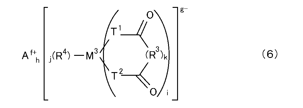
で表される化合物(以下「フルオロオキサラト化合物(6)」ともいう)からなる群より選択される少なくとも一種をさらに含んでいてもよい。これら化合物(4)、(5)及び(6)は、それぞれ単独で用いてもよく、2種類以上を併用してもよい。
非水電解液は、リチウムイオン二次電池の各種特性の向上を目的とする他の添加剤(前記化合物(4)、(5)、(6)とは異なる添加剤)を含んでいてもよい。他の添加剤としては、無水コハク酸、無水グルタル酸、無水マレイン酸、無水シトラコン酸、無水グルタコン酸、無水イタコン酸、無水ジグリコール酸、シクロヘキサンジカルボン酸無水物、シクロペンタンテトラカルボン酸二無水物、フェニルコハク酸無水物等のカルボン酸無水物;エチレンサルファイト、1,3-プロパンスルトン、1,4-ブタンスルトン、メタンスルホン酸メチル、ブサルファン、スルホラン、スルホレン、ジメチルスルホン、テトラメチルチウラムモノスルフィド、トリメチレングリコール硫酸エステル等の含硫黄化合物;1-メチル-2-ピロリジノン、1-メチル-2-ピペリドン、3-メチル-2-オキサゾリジノン、1,3-ジメチル-2-イミダゾリジノン、N-メチルスクシンイミド等の含窒素化合物;ヘプタン、オクタン、シクロヘプタン等の飽和炭化水素化合物;フルオロエチレンカーボネート(FEC)、トリフルオロプロピレンカーボネート、フェニルエチレンカーボネート及びエリスリタンカーボネート等のカーボネート化合物;スルファミン酸(アミド硫酸、H3NSO3);スルファミン酸塩(リチウム塩、ナトリウム塩、カリウム塩等のアルカリ金属塩;カルシウム塩、ストロンチウム塩、バリウム塩等のアルカリ土類金属塩;マンガン塩、銅塩、亜鉛塩、鉄塩、コバルト塩、ニッケル塩等の他の金属塩;アンモニウム塩;グアニジン塩等)等が挙げられる。他の添加剤は、それぞれ単独で用いてもよく、2種類以上を併用してもよい。
本実施形態に係る二次電池は、正極、負極及び非水電解液を備えている。この二次電池では、非水電解液は、スルホニルイミド化合物(1)を含み、且つCO2等を20質量ppm以上溶存している。換言すると、この二次電池に含まれる非水電解液は、本実施形態に係る非水電解液(CO2等溶存電解液)に相当するものである。
正極は、正極集電体及び正極合材層を含み、正極合材層が正極集電体上に形成され、通常、シート状に成形されている。
[化7]
LizNixMnyCo(1-x-y)O2 (z:0.9≦z≦1.1、x:0.2≦x<1、y:0≦y≦0.4、0<1-x-y≦0.8) (7)
で表される三元系正極活物質(以下「三元系正極活物質(7)」という)及び一般式(8):
[化8]
LipFe1-rQr(PO4)p (Q:Mn又はNi、p:0.9≦p≦1.1、r:0≦r≦0.05) (8)
で表される正極活物質(以下「リン酸鉄系正極活物質(8)」という)の少なくとも一種を含む。これら正極活物質は、それぞれ単独で用いてもよく、2種類以上を併用してもよい。
負極は、負極集電体及び負極合材層を含み、負極合材層が負極集電体上に形成され、通常、シート状に成形されている。
二次電池はセパレータを備えていてもよい。セパレータは正極と負極とを隔てるように配置されるものである。セパレータには、特に制限がなく、本開示では、従来公知のセパレータのいずれも使用できる。具体的なセパレータとしては、例えば、電解液(非水電解液)を吸収・保持し得るポリマーからなる多孔性シート(例えば、ポリオレフィン系微多孔質セパレータやセルロース系セパレータなど)、不織布セパレータ、多孔質金属体等が挙げられる。
正極、負極及び非水電解液(さらにはセパレータ)を備えた電池素子は、通常、電池使用時の外部からの衝撃、環境劣化等から電池素子を保護するため電池外装材に収容される。電池外装材の素材は特に限定されず従来公知の外装材はいずれも使用できる。
本実施形態に係る二次電池は、例えば、正極と負極とを(必要に応じてセパレータを介して)重ね合わせ、得られた積層体を電池外装材に入れ、電池外装材に非水電解液を注液して封口することにより、容易に製造できる。
(A)非水電解液の調製工程において、非水電解液にCO2等を溶存させる、具体的には、非水電解液として、本実施形態に係る非水電解液(CO2等溶存電解液)を用いる、又は
(B)二次電池の製造工程において、非水電解液にCO2等を溶存させる、具体的には、CO2雰囲気下で非水電解液を電池内に注液する、若しくは非水電解液を注液した後の電池内の空気をCO2に置換する。
(1-1)非水電解液(リファレンス電解液)の調製
電解液溶媒としてエチレンカーボネート(EC):エチルメチルカーボネート(EMC)=3:7(体積比)組成の混合溶媒(キシダ化学(株)製、以下同じ)に、LiFSI((株)日本触媒製、以下同じ)及びLiPF6(ステラケミファ(株)製、以下同じ)を含む混合塩組成の電解質塩、又はLiPF6のみを含む単体塩組成の電解質塩をそれぞれ表1-1に示す濃度となるように溶解することにより、非水電解液(以下単に「電解液」ともいう)を調製した。なお、比較電解液1-2には、ビニレンカーボネート(VC)を2質量%となるようにさらに添加した。以下の説明において、意図的にCO2等が溶存されていない非水電解液を「リファレンス電解液」という。このリファレンス電解液は、溶存工程を経ずに(溶存工程前に)得られるものであり、原料中のCO2等や不可避的に溶存されるCO2等を含んでいてもよい。得られたリファレンス電解液をガスクロマトグラフィーで分析し、当該電解液中におけるCO2の溶存量を定量した結果を表1-1の「リファレンス電解液」欄に示す。
ガスクロマトグラフィーで測定する際には、測定系に大気が混入しないように、ガスクロマトグラフィー装置を窒素でパージした状態(窒素雰囲気下)で、当該装置に非水電解液又は検量線ガスを直接投入した。ガスクロマトグラフィーの具体的な測定条件は以下のとおりである。
・気化室温度:130℃
・検出器温度:300℃(BID)
・キャリアガス:ヘリウム(カラム流量1.33mL/分)
・注入量:1μL(スプリット法、スプリット比:5.0)。
CO2混合比が既知の、複数種の標準ヘリウムガスを、上記の注入量(1μL)を1mLに変更したこと以外は上記のガスクロマトグラフィーの測定条件と同様の条件で分析し、得られたCO2ガスのピーク面積から、CO2混合量(溶存量)とCO2ガスのピーク面積との関係を示す検量線を作成した。続いて、各実施例で得られた非水電解液をガスクロマトグラフィーで分析した。最後に、外部標準法により、各非水電解液中におけるCO2の溶存量を定量した。
前記「(1-1)非水電解液(リファレンス電解液)の調製」で得られた各電解液を、密閉ボトルに当該ボトルの容積の1/10程度となるように入れた。続いて、デシケーター内に、当該ボトルをその開口部が上方に位置するように静置した後、デシケーター内を真空ポンプで40mmHgまで真空引きを行った。次いで、デシケーター内にCO2を供給して充填した。この処理を3回繰り返し、当該ボトル内の空気をCO2で置換した。その後、当該ボトルを密閉し、冷蔵庫内で3日間保存することにより、CO2溶存電解液を調製した。得られたCO2溶存電解液をガスクロマトグラフィーで分析し、当該電解液中におけるCO2の溶存量を定量した結果を表1-1の「(A)CO2溶存電解液」欄に示す。
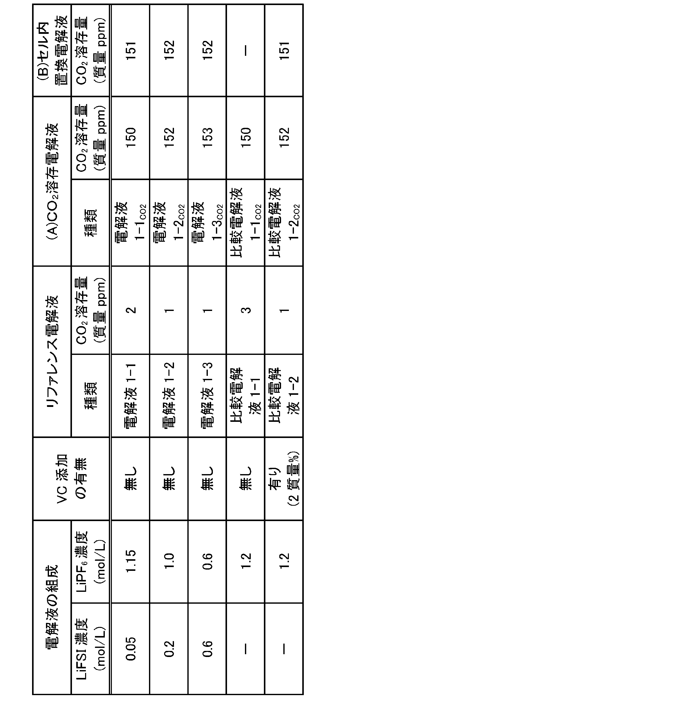
(正極の作製)
三元系正極活物質であるLiNi1/3Co1/3Mn1/3O2(ユミコア製、品番:MX7h)、アセチレンブラック(AB、デンカ(株)製、製品名:デンカブラック(登録商標))、グラファイト(日本黒鉛工業(株)製、品番:SP270)、及びポリフッ化ビニリデン(PVdF、(株)クレハ製、品番:KF1120)をN-メチル-2-ピロリドン(NMP)中に分散させて正極合材スラリー(正極活物質:AB:グラファイト:PVdF=93:2:2:3(固形分質量比))を作製した。続いて、得られた正極合材スラリーをアルミニウム箔(正極集電体、日本製箔(株)製、厚み15μm)に対して、乾燥後の塗工重量が19.4mg/cm2となるようにアプリケーターで片面塗工し、110℃のホットプレート上で10分間乾燥させた。さらに、110℃の真空乾燥炉で12時間乾燥させた。その後、ロールプレス機により密度3.1g/cm3となるまで加圧成形することにより、シート状(厚み83μm)の正極を得た。
負極活物質としてグラファイト(天然黒鉛(日立化成(株)製、品番:SMG):人造黒鉛(TIMCAL製、品番:SFG15)=85:15(固形分質量比))、スチレン-ブタジエンゴム(SBR、結着剤)及びカルボキシメチルセルロース(CMC、結着剤)を、超純水中に分散させて、負極合材スラリー(負極活物質:SBR:CMC=97.3:1.5:1.2(固形分質量比))を作製した。続いて、得られた負極合材スラリーを銅箔(負極集電体、福田金属箔粉工業(株)製、厚み15μm)に対して、乾燥後の塗工重量が9.8mg/cm2となるようにアプリケーターで片面塗工し、80℃のホットプレート上で10分間乾燥させた。さらに、100℃の真空乾燥炉で12時間乾燥させた。その後、ロールプレス機により密度1.3g/cm3となるまで加圧成形することにより、シート状(厚み113μm)の負極を得た。
得られた正極及び負極をそれぞれカットし、極性導出リードを超音波で溶接し、16μmのポリエチレン(PE)セパレータを介して該正極及び負極を対向させ、ラミネート外装で3方を封止することにより、未注液電池を作製した。続いて、未注液電池の未封止の1方より、表1-1又は表1-2に示す各電解液を700μL添加した。電解液の注液後、真空封止を行うことにより、4.2V、容量30mAhのラミネート電池(セル)1-1を作製した。
前記と同様の方法により、未注液電池を作製し、未注液電池の未封止の1方より、表1-1に示す各電解液を700μL添加した。電解液の注液後、デシケーター内に、注液後の電池をその開口部が上方に位置するように静置した後、デシケーター内を真空ポンプで40mmHgまで真空引きを行った。次いで、デシケーター内にCO2を供給して充填した。この処理を3回繰り返し、当該電池内の空気をCO2で置換した後、常圧封止を行うことにより、4.2V、容量30mAhのラミネート電池(セル)1-2を作製した。その後、セル1-1と同様の手順により、セル1-2のエージング工程を行った。
(自己放電)
エージング後のセルを、常温にて1C(30mA)、4.2Vで0.02C(0.6mA)終止の定電流定電圧充電を行い、満充電状態とし、60℃で4週間保存し、保存前後のセルの開路電圧(OCV:Open Circuit Voltage)を測定した。その結果を表1-2に示す。なお、保存前のOCV(測定値)に対して、保存後のOCV(測定値)の低下の度合い(以下、単に「OCVの低下度」ともいう)が小さいほど、電池の自己放電が抑制されていることを意味する。
エージング後のセルを、常温にて0.2C(6mA)で2.75Vまで放電後、常温にて4.2V、1C(30mA)で30分の定電流充電をして充電深度(SOC)50%にし、25℃又は-30℃の条件下で、インピーダンスアナライザ(Bio Logic製、品番:VSP-300)を用い、周波数1GHzから10mHz(25℃)又は1mHz(-30℃)までのインピーダンス測定を行った。得られた測定値の円弧が発散する周波数から、実軸抵抗(界面抵抗)を求めた。その結果を表1-2に示す。なお、円弧が発散する周波数とは、25℃測定の場合、周波数100Hz~0.01Hzの間で虚軸数値が極小を迎えた周波数をいい、-30℃の測定の場合、周波数10Hz~0.001Hzの間で虚軸数値が極小を迎えた周波数いう。
エージング後のセルを、常温にて1C(30mA)、4.2Vで0.02C(0.6mA)終止の定電流定電圧充電を行い、満充電状態(SOC100%)又は充電深度(SOC)50%とした。続いて、満充電状態(SOC100%)又は充電深度(SOC)50%から、30分間放置後に6mAで10秒間放電し、続いて30分間放置後に30mAで10秒間放電し、さらに30分間放置後に60mAで10秒間放電した。各放電電流を横軸に、各放電電流での放電開始時と10秒後の閉路電圧の差(ΔV)を縦軸にプロットし、そのI-V直線の傾きをセルのDCRとした。その結果を表1-2に示す。
インピーダンス測定後のセルを、25℃にて0.2C(6mA)で2.75Vまで放電後、25℃にて4.2V、1C(30mA)で0.02C(0.6mA)終止の定電流定電圧充電を行った。充電後のセルを-20℃で3時間放置後、-20℃にて1C(30mA)、2.75V終止の定電流放電容量を測定した。続いて、-20℃にて定電流放電容量を測定した後のセルを常温で3時間放置後、25℃にて0.2C(6mA)、2.75V終止の定電流放電を行った。放電後のセルを、-20℃で3時間放置後、-20℃にて1C(30mA)、4.2V終止の定電流充電容量を測定した。その結果を表1-2に示す。
エージング後のセルを、45℃にて、以下の充放電条件(サイクル条件)で、合計300サイクルのサイクル試験を行った。300サイクル後の容量維持率を以下の数式(1):
[数1]
容量維持率(%)=(300サイクル目の1C容量/1サイクル目の1C容量)×100 (1)
に基づいて求めた。その結果を表1-2に示す。
・充電:4.2V、1C(30mA)で定電流定電圧充電、0.02C(0.6mA)終止、10分間休止。
・放電:1C(30mA)で定電流(CC)放電、2.75V終止、10分間休止。
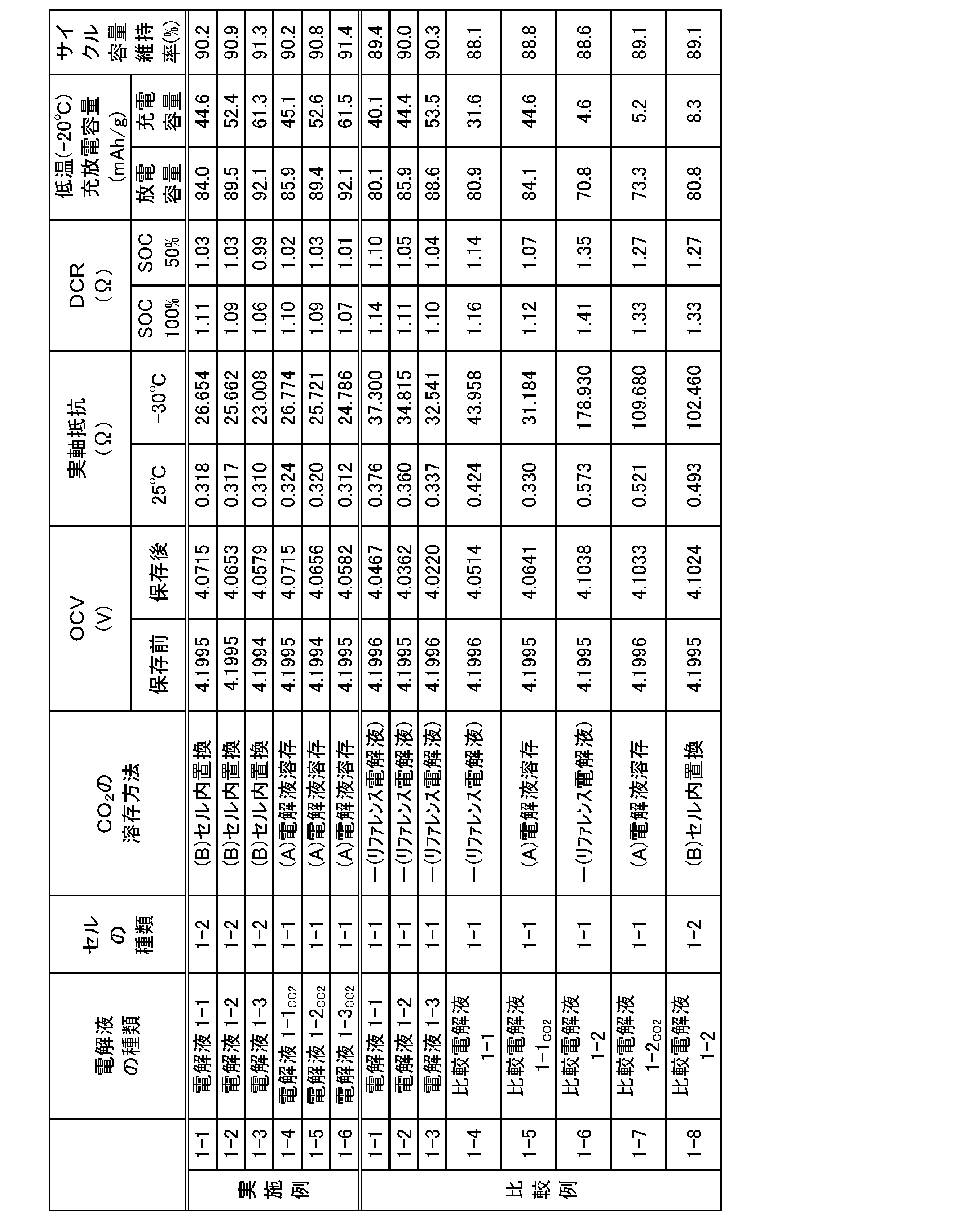
[数2]
実施例1-1のOCVの低減率(%)=[{(実施例1-1の保存前のOCV)-(実施例1-1の保存後のOCV)}/{(比較例1-1の保存前のOCV)-(比較例1-1の保存後のOCV)}]×100 (2)
により求めることができる。なお、OCVの低減率は、その値が小さいほど、電池の自己放電が抑制されている、即ち、自己放電抑制の効果に優れる(自己放電抑制の効果(程度)が高い)ことを意味する。

表1-2の結果から、LiFSI(スルホニルイミド化合物(1))を含む電解液を用いた電池(比較例1-1~1-3)は、その濃度に依存して保存後のOCVの低下度が大きく(即ち、満充電状態からの自己放電が大きく)、またLiPF6を単独で含む電解液を用いた電池(比較例1-4及び1-6)と比較して、OCVの低下度が大きいことが分かった。また、これらの電池は、電解液にCO2を溶存又はセル内部の空気をCO2に置換する方法により、電解液にCO2を溶存させることで、OCVの低下が抑制される(即ち、自己放電が抑制される)ことが分かった。
表1-2の結果から、CO2を溶存させた電解液を用いた電池はいずれも、意図的にCO2を溶存させていないリファレンス電解液を用いた電池と比較して、インピーダンスが大幅に低下した(比較例1-1と実施例1-1,1-4との対比;比較例1-2と実施例1-2,1-5との対比;比較例1-3と実施例1-3,1-6との対比)。このインピーダンス低下の効果は、特に低温において顕著に表れている。なお、電解液にVCが添加された比較例1-6~1-8では、CO2溶存の有無にかかわらず、低温でのインピーダンスが著しく高いことが分かった。
表1-2の結果から、CO2を溶存させた電解液を用いた電池はいずれも、意図的にCO2を溶存させていないリファレンス電解液を用いた電池と比較して、DCRが大幅に低下した(対比対象は前記と同じ)。このDCR低下の効果は、SOC100%及びSOC50%とも同様に確認されたことから、電池の充電状態によらず、当該効果が得られることを示唆している。なお、電解液にVCが添加された比較例1-6~1-8では、CO2溶存の有無にかかわらず、DCRが著しく高いことが分かった。
表1-2の結果から、CO2を溶存させた電解液を用いた電池はいずれも、意図的にCO2を溶存させていないリファレンス電解液を用いた電池と比較して、低温での充放電容量が向上した(対比対象は前記と同じ)。なお、電解液にVCが添加された比較例1-6~1-8では、CO2溶存の有無にかかわらず、特に低温での放電容量が低いことが分かった。これは、インピーダンス測定結果に示したしたように、低温でのインピーダンスが著しく高いためと考えられる。
表1-2の結果から、CO2を溶存させた電解液を用いた電池はいずれも、意図的にCO2を溶存させていないリファレンス電解液を用いた電池と比較して、300サイクル容量維持率が向上した(対比対象は前記と同じ)。
前記「(1-1)非水電解液(リファレンス電解液)の調製」で得られた電解液1-3(リファレンス電解液)を密閉ボトルに当該ボトルの容積の1/10程度となるように入れた。続いて、オートクレーブ内に、当該ボトルをその開口部が上方に位置するように静置した後、CO2で0.3MPaまで加圧した。次いで、リリース弁を半開放してオートクレーブ内圧を0.15MPaまで下げた。この処理を3回繰り返し、オートクレーブ内の空気をCO2に置換した。置換後、再びCO2で0.3MPaまで加圧し、所定の時間(0.3MPaでの静置時間は以下の表1-4を参照)静置した。静置後の電解液をオートクレーブから取り出し、密閉状態にて、24℃でさらに1週間静置した。1週間静置した後、0.3MPaでの静置時間を15分間とした電解液(実施例1-9)の一部を分け取り、リファレンス電解液を用いて2倍(実施例1-8)、4倍(実施例1-7)又は10倍(比較例1-10)に希釈した。得られたCO2溶存電解液をガスクロマトグラフィーで分析し、当該電解液中におけるCO2の溶存量と、リファレンス電解液に対するCO2溶存量の増加量とを定量した結果を表1-4に示す。
前記「(1-3)ラミネート電池1-1の作製」と同様の方法により、4.2V、容量30mAhのラミネート電池(セル)1-1を作製した後、セル1-1のエージング工程を行った。窒素雰囲気中でラミネートを開裂し、電解液を抜き取った。抜き取った電解液をガスクロマトグラフィーで分析し、当該電解液中におけるCO2の溶存量を定量した結果を表1-4及び表1-5の「エージング後のCO2溶存量」欄に示す。
(インピーダンス及び自己放電)
前記「(1-5)電池の評価」と同様の方法により、セルの自己放電(OCV)及びインピーダンスを測定した。その結果を表1-4に示す。


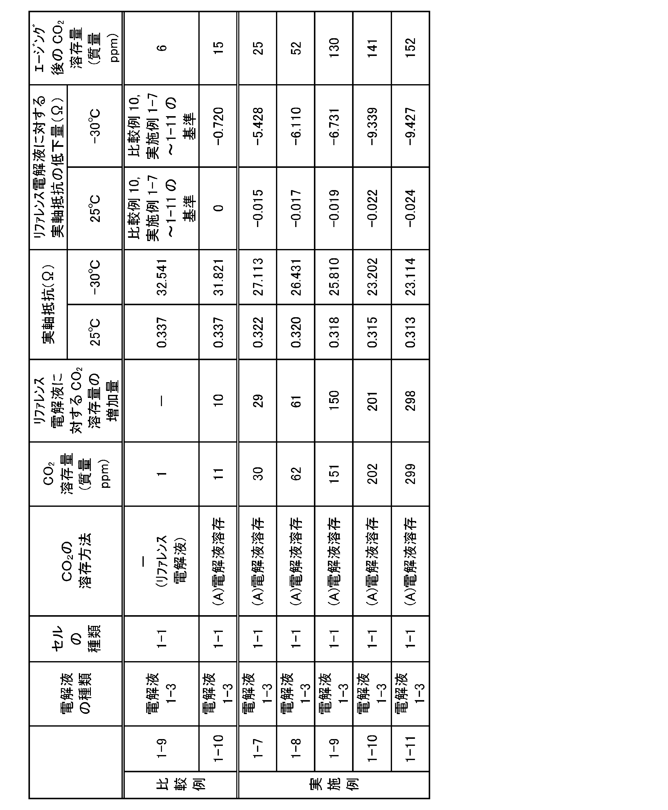
表1-4の結果から、溶存工程により非水電解液中にCO2を20質量ppm以上溶存させた電解液を用いた電池(各実施例)は、溶存工程を経ず、非水電解液中にCO2を1質量ppm溶存するリファレンス電解液(電解液1-3)を用いた電池(比較例1-9)及び非水電解液中にCO2を11質量ppm溶存する電解液を用いた電池(比較例1-10)と比較して、保存後のOCVの低下度が小さく、電池の自己放電が抑制されることが分かった。また、表1-5の結果から、CO2溶存量及びリファレンス電解液に対するCO2溶存量の増加量が大きくなるにつれて自己放電抑制の効果が増大した。これより、CO2溶存量と自己放電抑制の効果は、比例関係にあることが分かった。
表1-4の結果から、各実施例の電池は、各比較例の電池と比較して、インピーダンスが低下した。このインピーダンス低下の効果は、特に低温において顕著に表れている。また、表1-6の結果から、CO2溶存量及びリファレンス電解液に対するCO2溶存量の増加量が大きくなるにつれて、リファレンス電解液に対する実軸抵抗の低下量が大きくなっており、インピーダンス低下の効果が増大した。これより、CO2溶存量とインピーダンス低下の効果は、比例関係にあることが分かった。
表1-4の結果から、上述のエージング工程を行った後に、窒素雰囲気中でラミネートを開裂し、抜き取ったCO2溶存電解液中におけるCO2の溶存量(エージング後のCO2溶存量)は、エージング工程前(電解液調製後)のCO2溶存電解液中におけるCO2の溶存量と比較して、低減するものの、いずれの実施例でも20質量ppm以上であることが分かった。
以上の結果より、スルホニルイミド化合物(1)を含む非水電解液において、電池の抵抗を著しく増大させるおそれのあるVCを用いなくても、CO2等を20質量ppm以上溶存させることにより、当該電解液を用いた電池は、自己放電が抑制されることが確認された。また、スルホニルイミド化合物(1)を含む非水電解液を用いた電池は、スルホニルイミド化合物(1)を含まない非水電解液を用いた電池と比較して、自己放電がより一層抑制される(即ち、自己放電抑制の効果に優れる)ことが確認された。また、電池の抵抗(インピーダンス、DCR)の低下、低温充放電特性や充放電サイクル特性の向上等の点で、電池性能が改善することが確認された。
(2-1)非水電解液(リファレンス電解液)の調製
ジフルオロリン酸リチウム(LiPO2F2)を表2-1に記載の含有量となるように電解液にさらに添加し、溶解させたこと以外は、前記「(1-1)非水電解液(リファレンス電解液)の調製」と同様の方法により、非水電解液を調製した。得られた電解液の組成を表2-1に示す。得られたリファレンス電解液をガスクロマトグラフィーで分析し、当該電解液中におけるCO2の溶存量を定量した結果を表2-1の「リファレンス電解液」欄に示す。
前記「(2-1)非水電解液(リファレンス電解液)の調製」で得られた各電解液を用いて、前記「(1-2)CO2が溶存された非水電解液(CO2溶存電解液)の調製(前記(A)の方法、溶存工程:置換工程)」と同様の方法により、CO2溶存電解液を調製し、当該電解液をガスクロマトグラフィーで分析した。CO2溶存電解液中におけるCO2の溶存量を定量した結果を表2-1の「(A)CO2溶存電解液」欄に示す。
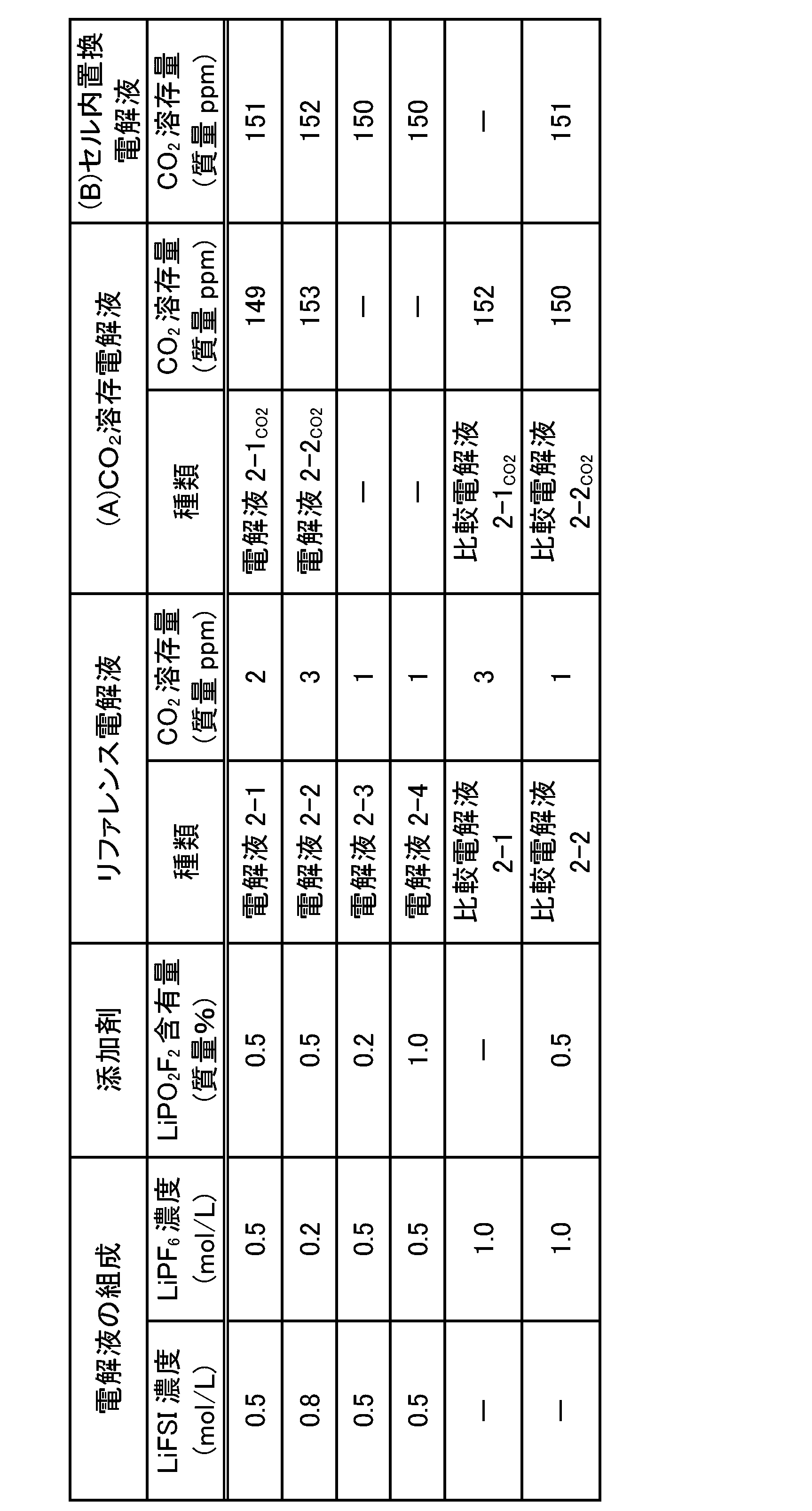
(正極の作製)
三元系正極活物質であるLiNi1/3Co1/3Mn1/3O2(ユミコア製、品番:MX7h)、アセチレンブラック(AB、デンカ(株)製、製品名:デンカブラック(登録商標))、グラファイト(日本黒鉛工業(株)製、品番:SP270)、及びポリフッ化ビニリデン(PVdF、(株)クレハ製、品番:KF1120)をN-メチル-2-ピロリドン(NMP)中に分散させて正極合材スラリー(正極活物質:AB:グラファイト:PVdF=93:2:2:3(固形分質量比))を作製した。
負極活物質としてグラファイト(天然黒鉛(日立化成(株)製、品番:SMG)、アセチレンブラック(AB、デンカ(株)製、製品名:デンカブラック(登録商標))、スチレン-ブタジエンゴム(SBR、結着剤)及びカルボキシメチルセルロース(CMC、結着剤)を、超純水中に分散させて、負極合材スラリー(天然黒鉛:アセチレンブラック:SBR:CMC=96:2:1:1(固形分質量比))を作製した。
得られた正極及び負極をそれぞれカットし、極性導出リードを超音波で溶接し、25μmのポリエチレン(PE)セパレータを介して該正極及び負極を対向させ、ラミネート外装で3方を封止することにより、未注液電池を作製した。続いて、未注液電池の未封止の1方より、表2-1に示す各電解液を500μL添加した。電解液の注液後、真空封止を行うことにより、4.2V、容量32mAhのラミネート電池(セル)2-1を作製した。
前記と同様の方法により、未注液電池を作製し、未注液電池の未封止の1方より、表2-1に示す各リファレンス電解液を500μL添加した。電解液の注液後、デシケーター内に、注液後の電池をその開口部が上方に位置するように静置した後、デシケーター内を真空ポンプで40mmHgまで真空引きを行った。次いで、デシケーター内にCO2を供給し充填させた。この処理を3回繰り返し、当該電池内の空気をCO2で置換した後、常圧封止を行うことにより、4.2V、容量35.8mAhのラミネート電池(セル)2-2を作製した。その後、セル2-1と同様の手順により、セル2-2のエージング工程を行った。
(インピーダンス、DCR及び低温充放電特性)
前記と同様の方法により、セルのインピーダンス、DCR及び低温(-20℃)充放電容量を測定した。その結果を表2-2に示す。
エージング後のセルを、常温にて0.5C(16mA)、4.2Vで0.02C(0.64mA)終止の定電流定電圧充電を行い、満充電状態とし、60℃で4週間保存し、保存前後のセルの開路電圧(OCV)を測定した。その結果を表2-2に示す。
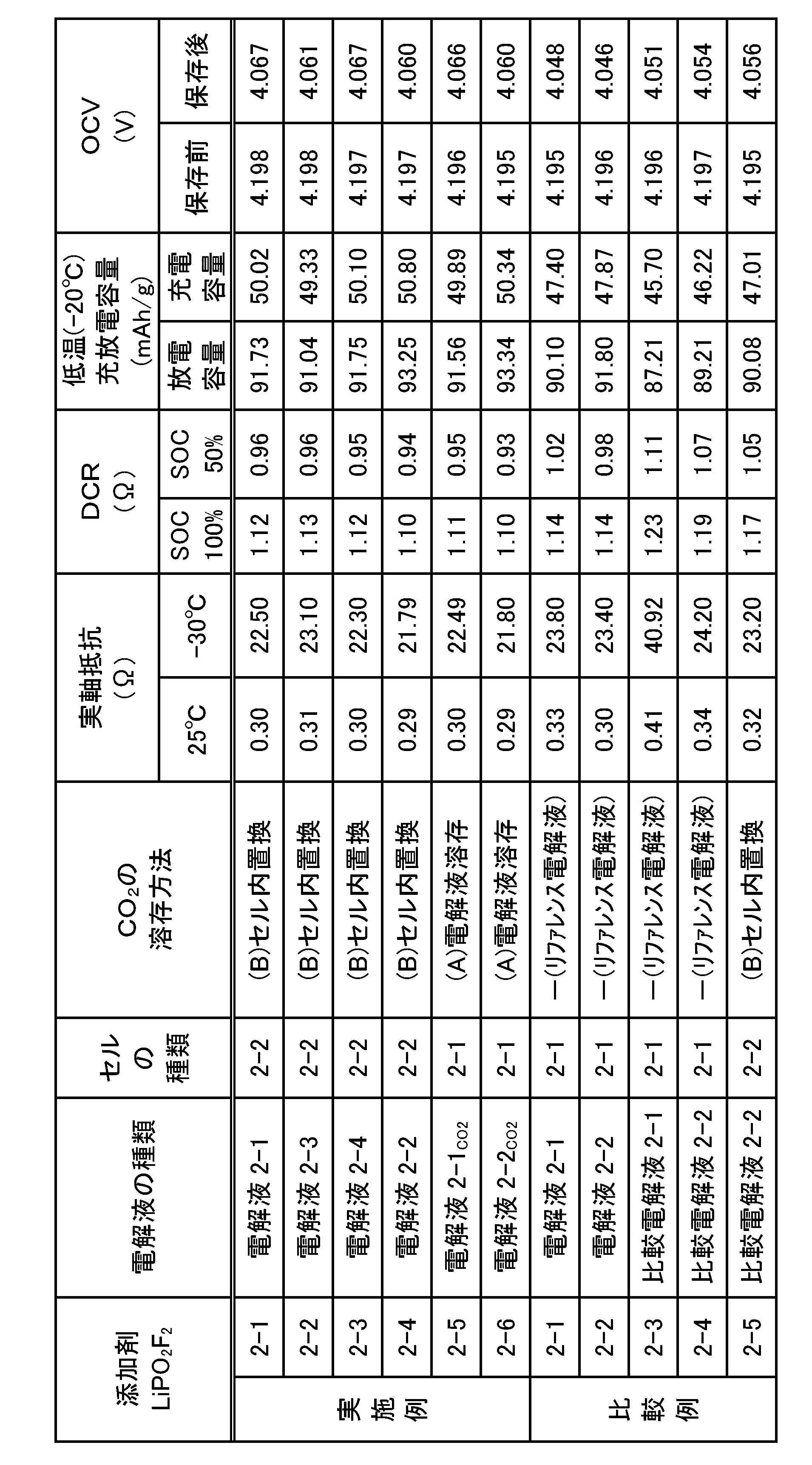
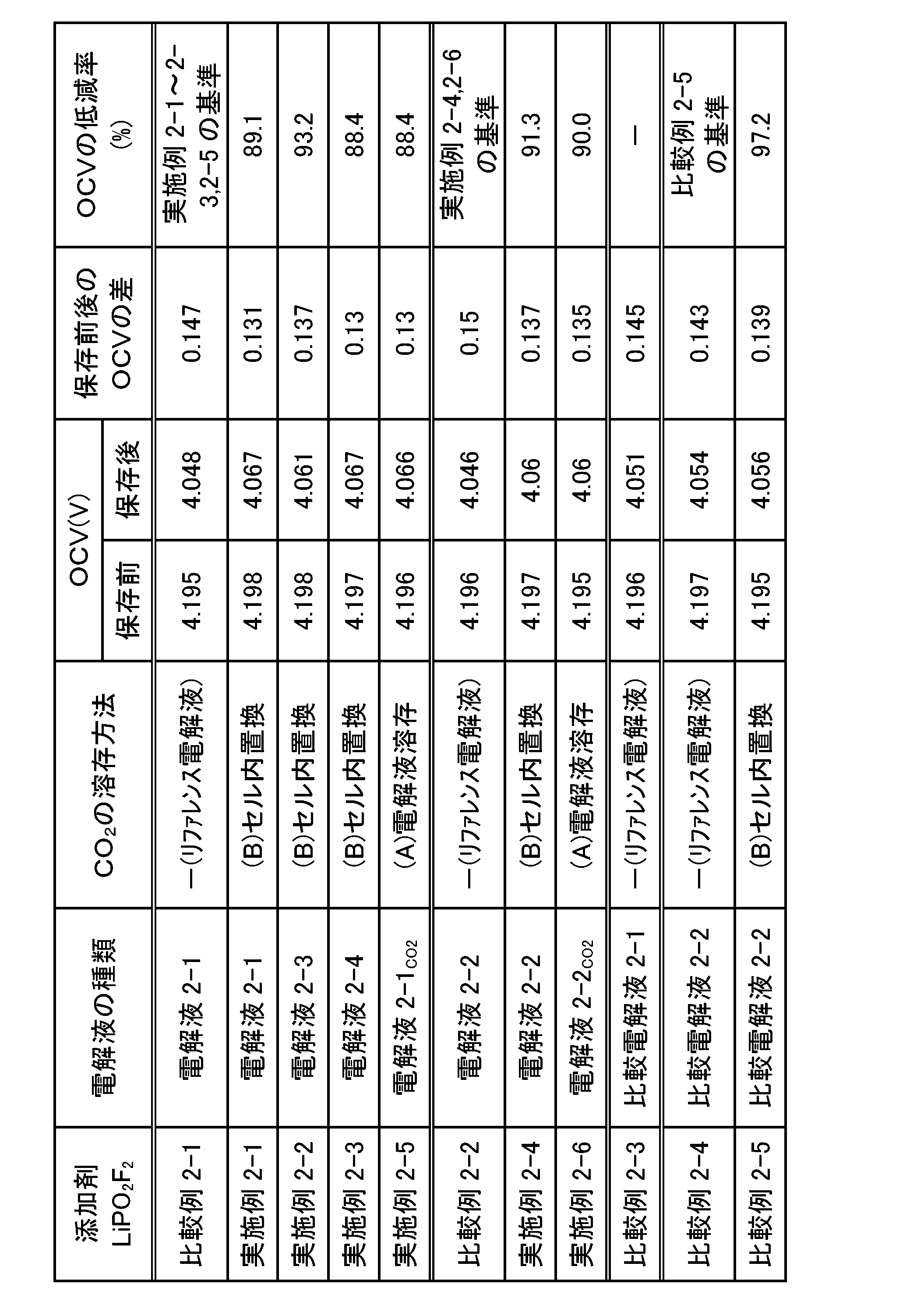
表2-2の結果から、電解液にCO2を溶存又はセル内部の空気をCO2に置換する方法により、CO2を溶存させた電解液を用いた電池はいずれも、意図的にCO2を溶存させていないリファレンス電解液を用いた電池と比較して、インピーダンスが低下した(比較例2-1と実施例2-1~2-3,2-5との対比;比較例2-2と実施例2-2,2-4との対比)。このインピーダンス低下の効果は、特に低温において顕著に表れている。
表2-2の結果から、CO2を溶存させた電解液を用いた電池はいずれも、意図的にCO2を溶存させていないリファレンス電解液を用いた電池と比較して、DCRが大幅に低下した(対比対象は前記と同じ)。このDCR低下の効果は、SOC100%及びSOC50%とも同様に確認されたことから、電池の充電状態によらず、当該効果が得られることを示唆している。
表2-2の結果から、CO2を溶存させた電解液を用いた電池はいずれも、意図的にCO2を溶存させていないリファレンス電解液を用いた電池と比較して、低温での充放電容量が向上した(対比対象は前記と同じ)。この効果は、インピーダンス測定結果に示した電解液へのCO2溶存による低温でのインピーダンス低下に基づくものと考えられる。
表2-2の結果から、CO2を溶存させた電解液を用いた電池はいずれも、意図的にCO2を溶存させていないリファレンス電解液を用いた電池と比較して、保存後のOCVの低下度が小さく、電池の自己放電が抑制されることが分かった(対比対象は前記と同じ)。
前記「(2-1)非水電解液(リファレンス電解液)の調製」で得られた電解液2-1(リファレンス電解液)を用いたこと以外は、前記「(1-6)加圧条件にてCO2が溶存された非水電解液(CO2溶存電解液)の調製(前記(A)の方法、溶存工程:加圧工程及び置換工程」に記載の方法で、各種CO2溶存量の非水電解液を作製した。得られたCO2溶存電解液をガスクロマトグラフィーで分析し、当該電解液中におけるCO2の溶存量と、リファレンス電解液に対するCO2溶存量の増加量とを定量した結果を表2-4に示す。
前記「(2-3)ラミネート電池2-1の作製」と同様の方法により、4.2V、容量30mAhのラミネート電池(セル)2-1を作製した後、セル2-1のエージング工程を行った。窒素雰囲気中でラミネートを開裂し、電解液を抜き取った。抜き取った電解液をガスクロマトグラフィーで分析し、当該電解液中におけるCO2の溶存量を定量した結果を表2-4及び表2-5の「エージング後のCO2溶存量」欄に示す。
(インピーダンス及び自己放電)
前記「(2-5)電池の評価」と同様の方法により、セルの自己放電(OCV)及びインピーダンスを測定した。その結果を表2-4に示す。
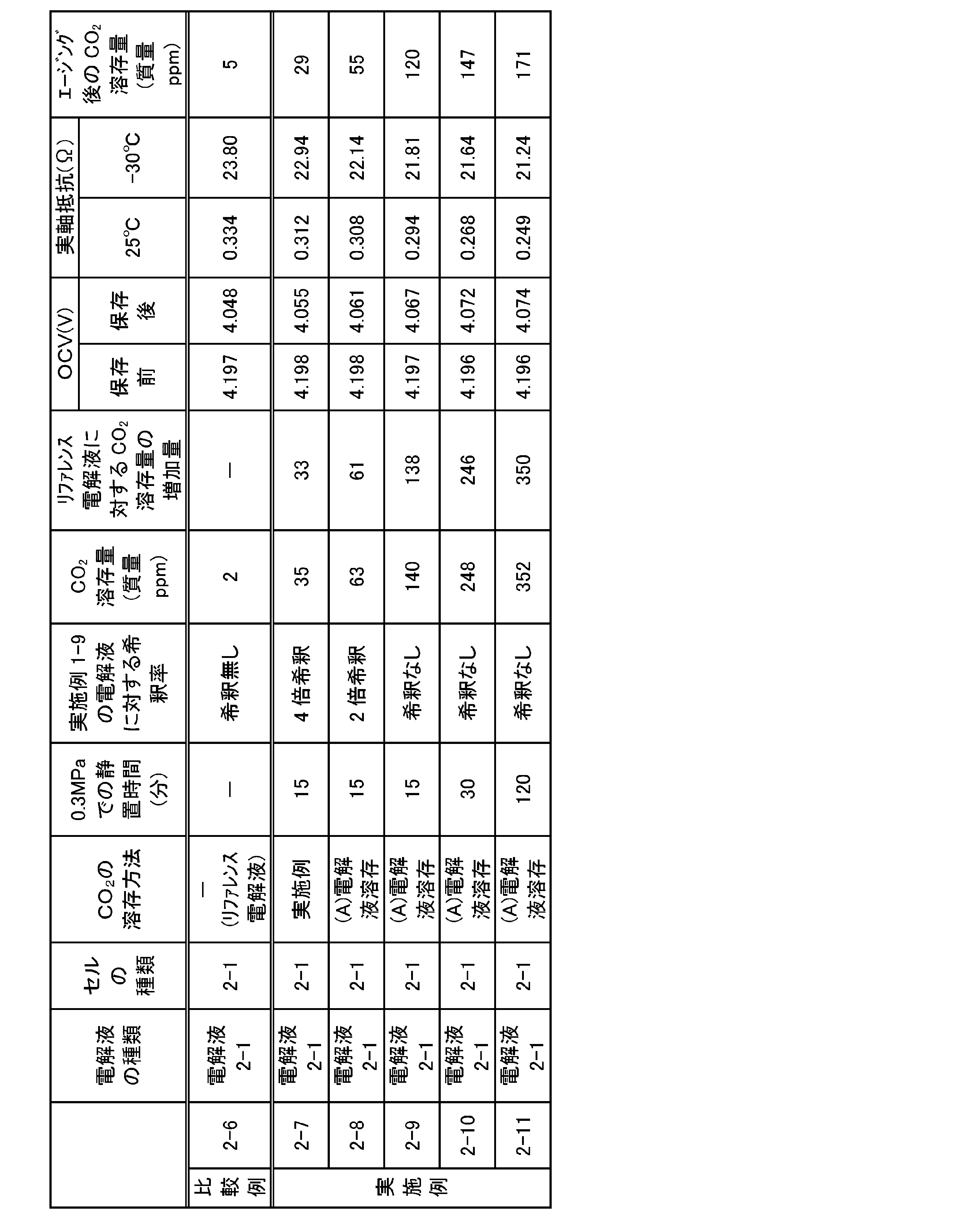
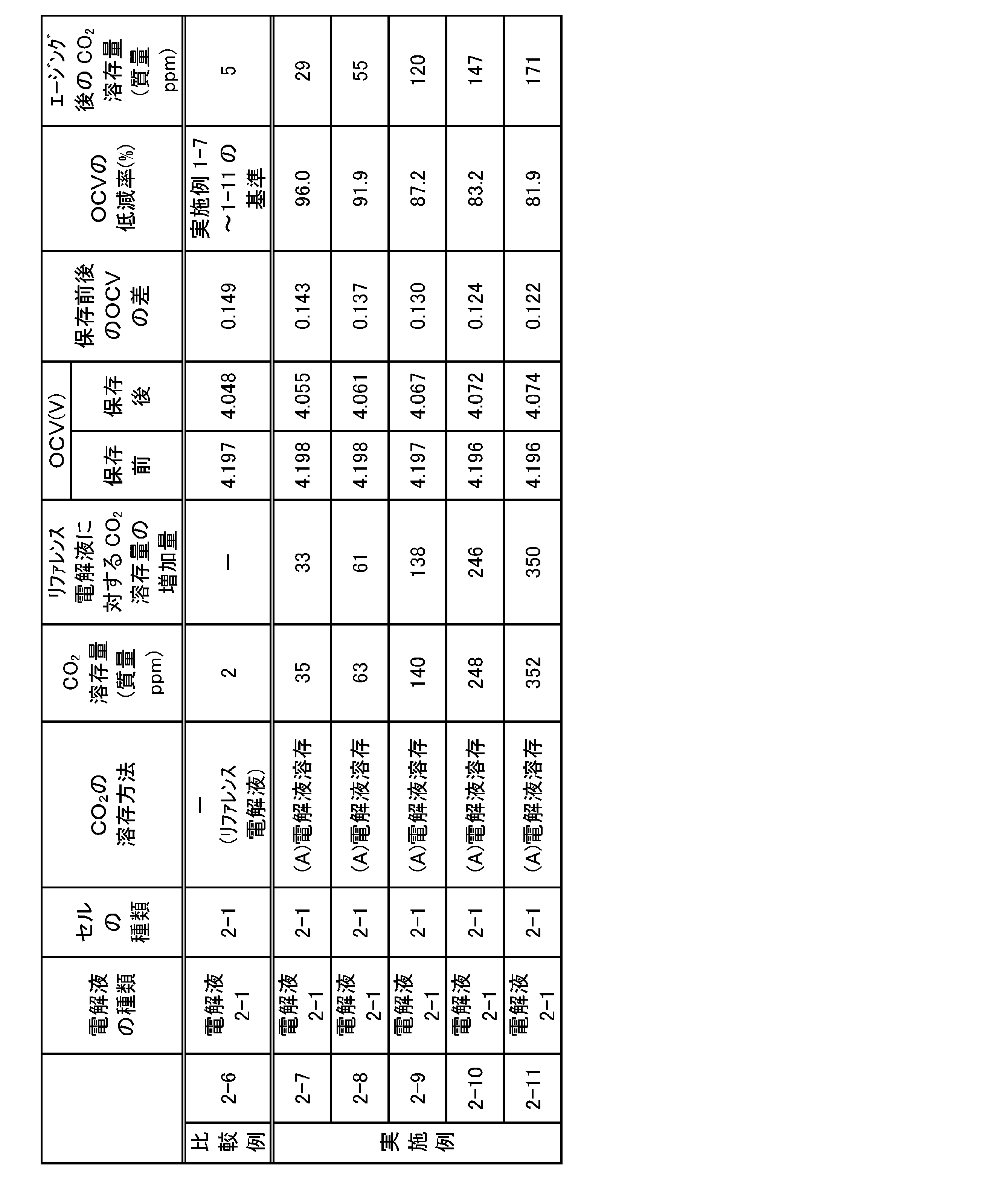

表2-4の結果から、溶存工程により非水電解液中にCO2を20質量ppm以上溶存させた電解液を用いた電池(各実施例)は、溶存工程を経ず、非水電解液中にCO2を2質量ppm溶存するリファレンス電解液(電解液2-1)を用いた電池(比較例2-6)と比較して、保存後のOCVの低下度が小さく、電池の自己放電が抑制されることが分かった。また、表2-5の結果から、CO2溶存量及びリファレンス電解液に対するCO2溶存量の増加量が大きくなるにつれて自己放電抑制の効果が増大した。これより、CO2溶存量と自己放電抑制の効果は、比例関係にあることが分かった。
表2-4の結果から、各実施例の電池は、比較例2-6の電池と比較して、インピーダンスが低下した。このインピーダンス低下の効果は、特に低温において顕著に表れている。また、表2-6の結果から、CO2溶存量及びリファレンス電解液に対するCO2溶存量の増加量が大きくなるにつれてインピーダンス低下の効果が増大した。これより、CO2溶存量とインピーダンス低下の効果は、比例関係にあることが分かった。
表2-4の結果から、上述のエージング工程を行った後に、窒素雰囲気中でラミネートを開裂し、抜き取ったCO2溶存電解液中におけるCO2の溶存量(エージング後のCO2溶存量)は、エージング工程前(電解液調製後)のCO2溶存電解液中におけるCO2の溶存量と比較して、低減するものの、いずれの実施例でも20質量ppm以上であることが分かった。
以上の結果より、スルホニルイミド化合物(1)を含む非水電解液において、各種電池性能を改善できるLiPO2F2の添加でも十分な効果が得られなかった電池の自己放電に関して、さらにCO2等を20質量ppm以上溶存させることにより、明確な効果が確認された。また、CO2等の溶存とLiPO2F2の添加との相乗効果により、電池の抵抗(インピーダンス、DCR)の低下、低温充放電特性や充放電サイクル特性の向上等の点で、電池性能がさらに改善することが確認された。
(3-1)非水電解液(リファレンス電解液)の調製
LiPO2F2の代わりにフルオロスルホン酸リチウム(LiFSO3)を電解液に添加し、溶解させたこと以外は、前記「(2-1)非水電解液(リファレンス電解液)の調製」と同様の方法により、非水電解液を調製した。得られた電解液の組成を表3-1に示す。得られたリファレンス電解液をガスクロマトグラフィーで分析し、当該電解液中におけるCO2の溶存量を定量した結果を表3-1の「リファレンス電解液」欄に示す。
前記「(3-1)非水電解液(リファレンス電解液)の調製」で得られた各電解液を用いて、前記「(1-2)CO2が溶存された非水電解液(CO2溶存電解液)の調製(前記(A)の方法、溶存工程:置換工程)」と同様の方法により、CO2溶存電解液を調製し、当該電解液をガスクロマトグラフィーで分析した。CO2溶存電解液中におけるCO2の溶存量を定量した結果を表3-1の「(A)CO2溶存電解液」欄に示す。
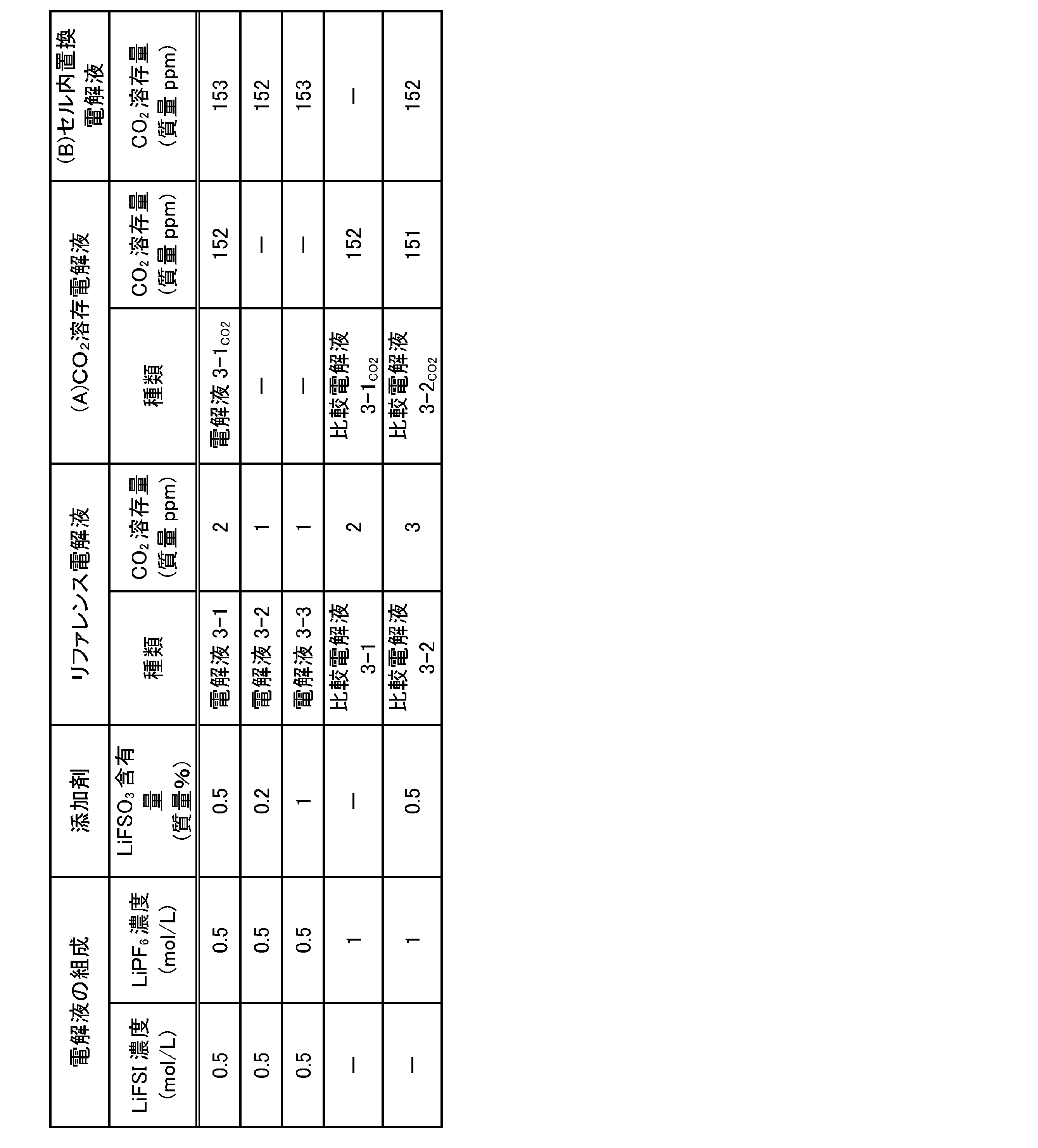
前記「(2-3)ラミネート電池2-1の作製」と同様の方法により、4.2V、容量32mAhのラミネート電池(セル)3-1を作製した後、セル3-1のエージング工程を行った。
前記「(2-4)ラミネート電池2-2の作製(前記(B)の方法)」と同様の方法により、4.2V、容量32mAhのラミネート電池(セル)3-2を作製した後、セル3-1と同様の手順により、セル3-2のエージング工程を行った。
(インピーダンス、低温充放電特性及び自己放電)
前記「(2-5)電池の評価」と同様の方法により、セルのインピーダンス、低温(-20℃)充放電容量及び自己放電(OCV)を測定した。その結果を表3-2に示す。

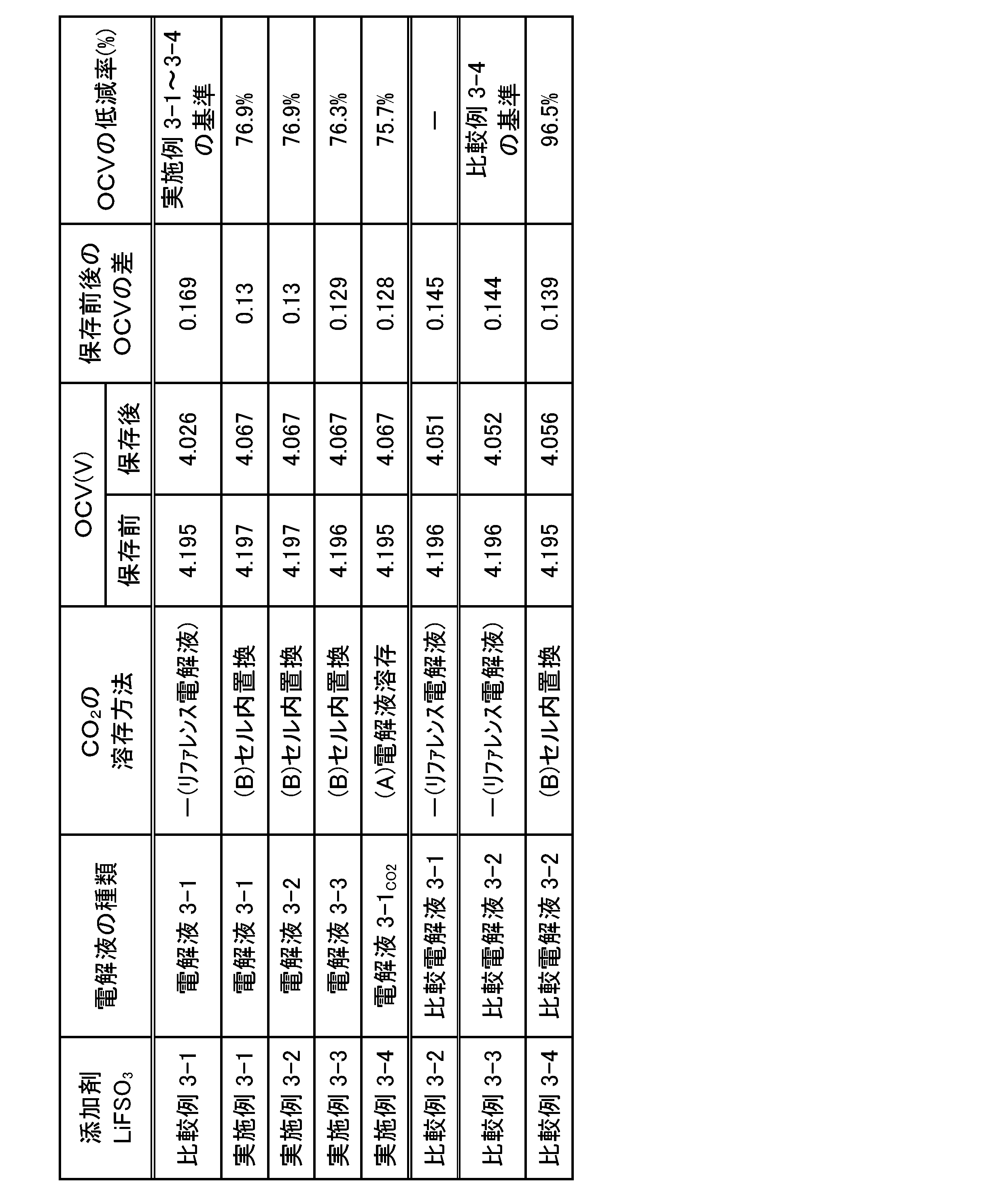
表3-2の結果から、電解液にCO2を溶存又はセル内部の空気をCO2に置換する方法により、CO2を溶存させた電解液を用いた電池はいずれも、意図的にCO2を溶存させていないリファレンス電解液を用いた電池と比較して、インピーダンスが低下した(比較例3-1と実施例3-1~3-4との対比)。このインピーダンス低下の効果は、特に低温において顕著に表れている。
表3-2の結果から、CO2を溶存させた電解液を用いた電池はいずれも、意図的にCO2を溶存させていないリファレンス電解液を用いた電池と比較して、低温での充放電容量が向上した(対比対象は前記と同じ)。この効果は、インピーダンス測定結果に示した電解液へのCO2溶存による低温でのインピーダンス低下に基づくものと考えられる。
表3-2の結果から、CO2を溶存させた電解液を用いた電池はいずれも、意図的にCO2を溶存させていないリファレンス電解液を用いた電池と比較して、保存後のOCVの低下度が小さく、電池の自己放電が抑制されることが分かった(対比対象は前記と同じ)。また、表3-3の結果から、LiFSI及びLiFSO3を含み且つCO2を溶存させた電解液を用いた電池(各実施例)はいずれも、LiFSIの代わりにLiPF6を単独で含む(LiFSO3を含み且つCO2を溶存させた)電解液を用いた電池(比較例3-4)と比較して、OCVの低減率が小さいため、自己放電がより一層抑制されることが分かった。
以上の結果より、スルホニルイミド化合物(1)を含む非水電解液において、LiFSO3をさらに含む場合でも、CO2等を20質量ppm以上溶存させることにより、電池の自己放電に関して明確な効果が確認された。また、CO2等の溶存とLiFSO3の添加との相乗効果により、電池の抵抗(インピーダンス)の低下や低温充放電特性の向上等の点で、電池性能がさらに改善することが確認された。
(4-1)非水電解液(リファレンス電解液)の調製
LiPO2F2の代わりにリチウムジフルオロオキサラトボレート(LiDFOB)を電解液に添加し、溶解させたこと以外は、前記「(2-1)非水電解液(リファレンス電解液)の調製」と同様の方法により、非水電解液を調製した。得られた電解液の組成を表4-1に示す。得られたリファレンス電解液をガスクロマトグラフィーで分析し、当該電解液中におけるCO2の溶存量を定量した結果を表4-1の「リファレンス電解液」欄に示す。
前記「(4-1)非水電解液(リファレンス電解液)の調製」で得られた各電解液を用いて、前記「(1-2)CO2が溶存された非水電解液(CO2溶存電解液)の調製(前記(A)の方法、溶存工程:置換工程)」と同様の方法により、CO2溶存電解液を調製し、当該電解液をガスクロマトグラフィーで分析した。CO2溶存電解液中におけるCO2の溶存量を定量した結果を表4-1の「(A)CO2溶存電解液」欄に示す。
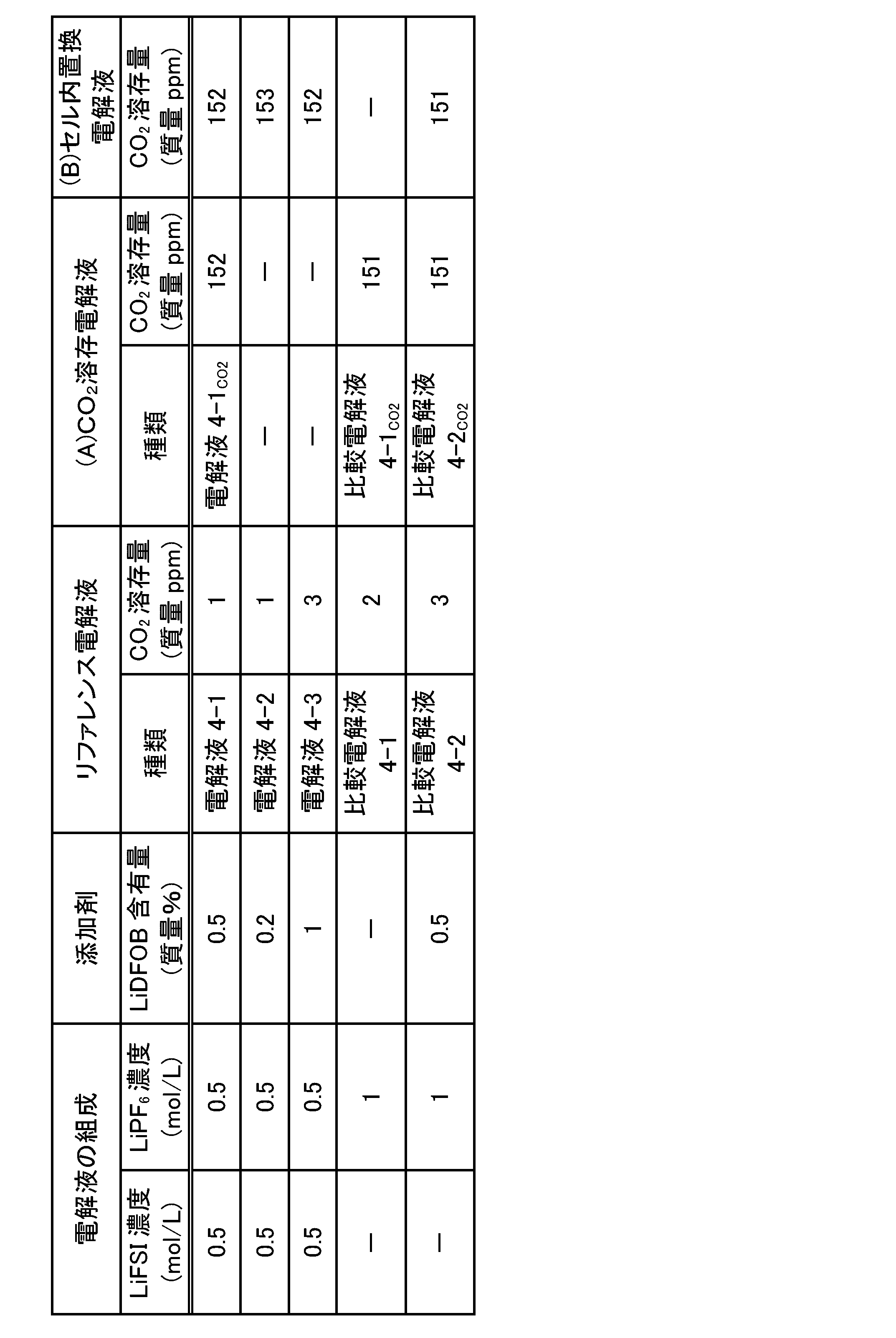
前記「(2-3)ラミネート電池2-1の作製」と同様の方法により、4.2V、容量35.8mAhのラミネート電池(セル)4-1を作製した後、セル4-1のエージング工程を行った。
前記「(2-4)ラミネート電池2-2の作製(前記(B)の方法)」と同様の方法により、4.2V、容量35.8mAhのラミネート電池(セル)4-2を作製した後、セル4-1と同様の手順により、セル4-2のエージング工程を行った。
(インピーダンス、低温充放電特性及び自己放電)
前記「(2-5)電池の評価」と同様の方法により、セルのインピーダンス、低温(-20℃)充放電容量及び自己放電(OCV)を測定した。その結果を表4-2に示す。
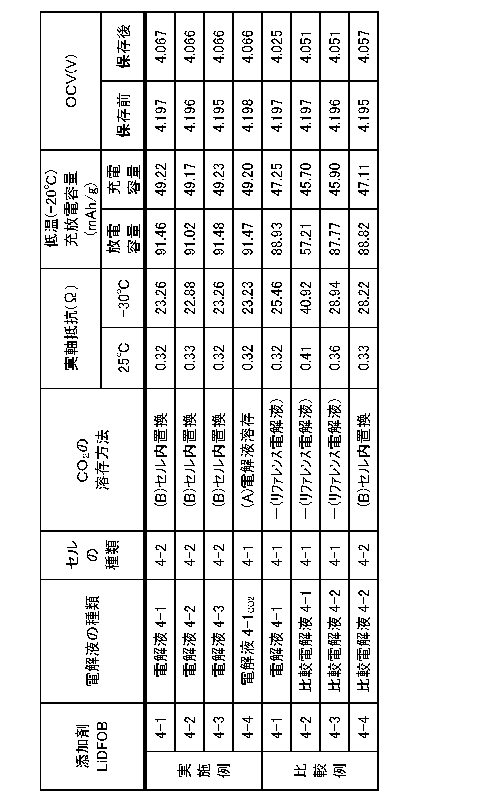
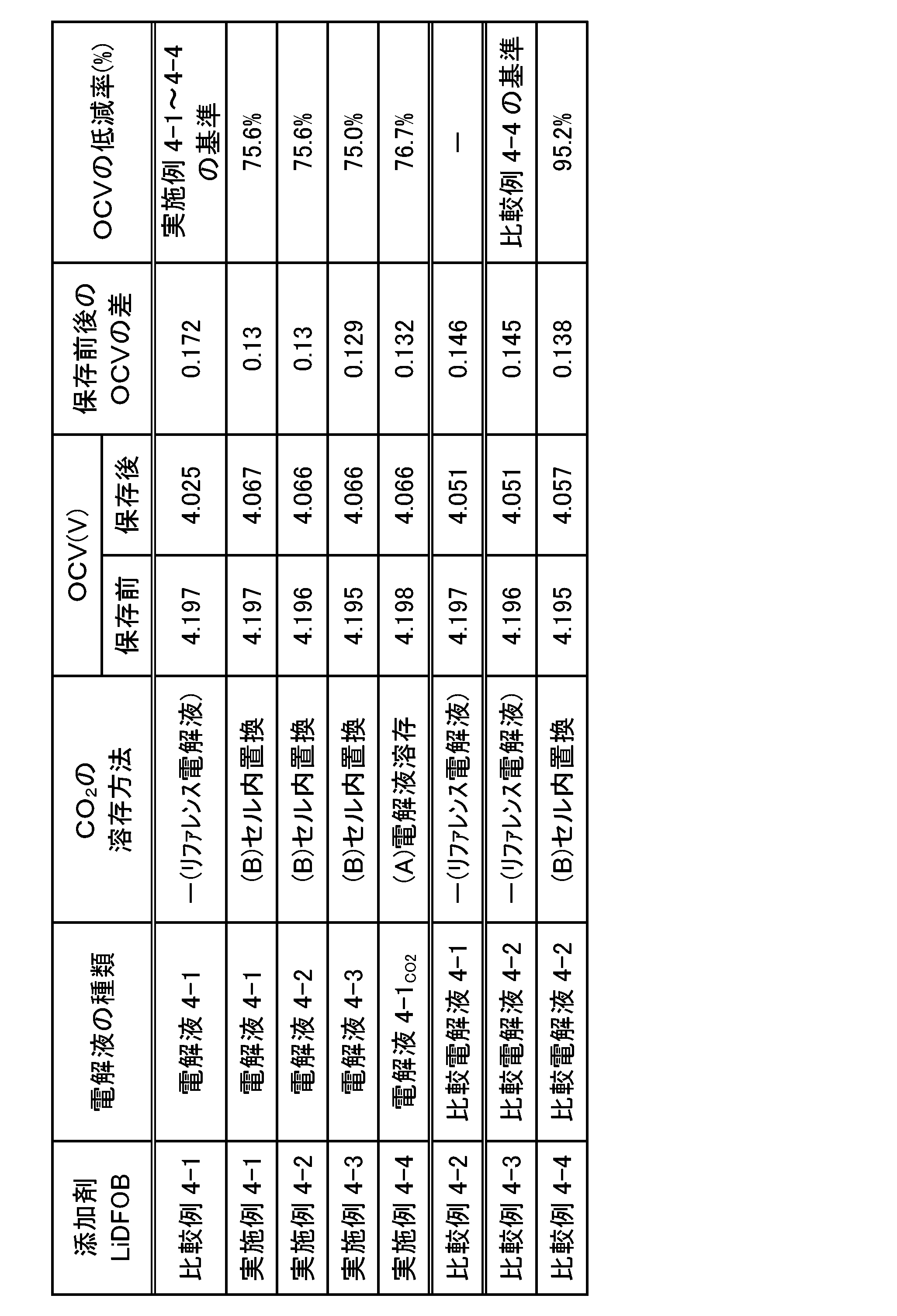
表4-2の結果から、電解液にCO2を溶存又はセル内部の空気をCO2に置換する方法により、CO2を溶存させた電解液を用いた電池はいずれも、意図的にCO2を溶存させていないリファレンス電解液を用いた電池と比較して、インピーダンスが低下した(比較例4-1と実施例4-1,4-4との対比)。このインピーダンス低下の効果は、特に低温において顕著に表れている。
表4-2の結果から、CO2を溶存させた電解液を用いた電池はいずれも、意図的にCO2を溶存させていないリファレンス電解液を用いた電池と比較して、低温での充放電容量が向上した(対比対象は前記と同じ)。この効果は、インピーダンス測定結果に示した電解液へのCO2溶存による低温でのインピーダンス低下に基づくものと考えられる。
表4-2の結果から、CO2を溶存させた電解液を用いた電池はいずれも、意図的にCO2を溶存させていないリファレンス電解液を用いた電池と比較して、保存後のOCVの低下度が小さく、電池の自己放電が抑制されることが分かった(対比対象は前記と同じ)。また、表4-3の結果から、LiFSI及びLiDFOBを含み且つCO2を溶存させた電解液を用いた電池(各実施例)はいずれも、LiFSIの代わりにLiPF6を単独で含む(LiDFOBを含み且つCO2を溶存させた)電解液を用いた電池(比較例4-4)と比較して、OCVの低減率が小さいため、自己放電がより一層抑制されることが分かった。
以上の結果より、スルホニルイミド化合物(1)を含む非水電解液において、LiDFOBをさらに含む場合でも、CO2等を20質量ppm以上溶存させることにより、電池の自己放電に関して明確な効果が確認された。また、CO2等の溶存とLiDFOBの添加との相乗効果により、電池の抵抗(インピーダンス)の低下や低温充放電特性の向上等の点で、電池性能がさらに改善することが確認された。
(5-1)非水電解液(リファレンス電解液)の調製
前記「(1-1)非水電解液(リファレンス電解液)の調製」と同様の方法により、非水電解液を調製した。得られた電解液の組成を表5-1に示す。得られたリファレンス電解液をガスクロマトグラフィーで分析し、当該電解液中におけるCO2の溶存量を定量した結果を表5-1の「リファレンス電解液」欄に示す。
前記「(5-1)非水電解液(リファレンス電解液)の調製」で得られた各電解液を用いて、前記「(1-2)CO2が溶存された非水電解液(CO2溶存電解液)の調製(前記(A)の方法、溶存工程:置換工程)」と同様の方法により、CO2溶存電解液を調製し、当該電解液をガスクロマトグラフィーで分析した。CO2溶存電解液中におけるCO2の溶存量を定量した結果を表5-1の「(A)CO2溶存電解液」欄に示す。

正極活物質として、以下の各実験例に示す三元系正極活物質(7)を用いたこと以外は、前記「(1-3)ラミネート電池1-1の作製」と同様の方法により、4.2V、容量30mAhのラミネート電池(セル)5-1を作製した後、セル5-1のエージング工程を行った。
正極活物質として、以下の各実験例に示す三元系正極活物質(7)を用いたこと以外は、前記「(1-4)ラミネート電池1-2の作製」と同様の方法により、4.2V、容量30mAhのラミネート電池(セル)5-2を作製した後、セル5-2のエージング工程を行った。
[実験例1]
実験例1では、正極活物質として、LiNi1/3Co1/3Mn1/3O2(ユミコア製、品番:MX7h)を用いた。
前記「(1-5)電池の評価」と同様の方法により、セルのインピーダンス、DCR及び自己放電(OCV)を測定した。その結果を表5-2に示す。

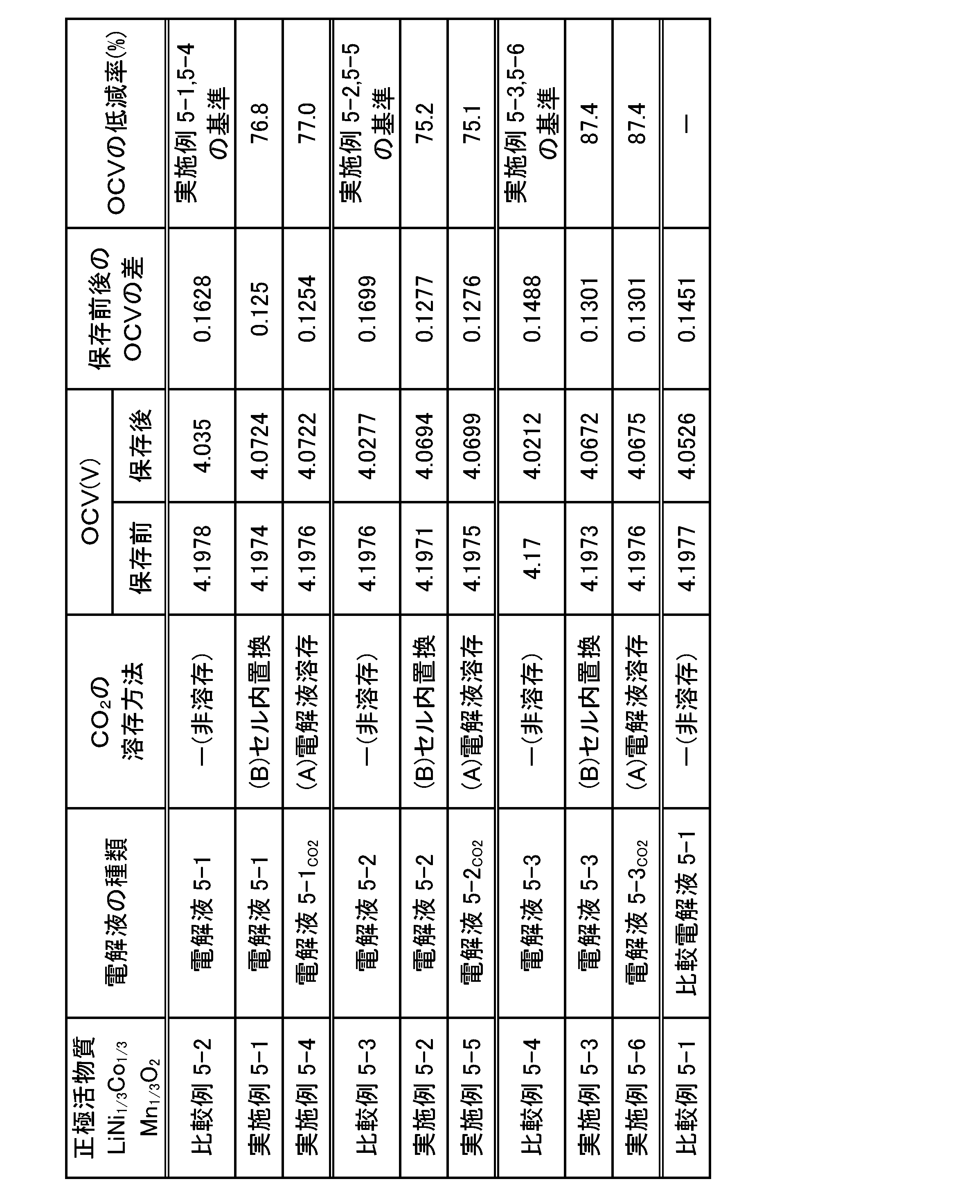
表5-2の結果から、電解液にCO2を溶存又はセル内部の空気をCO2に置換する方法により、CO2を溶存させた電解液を用いた電池はいずれも、意図的にCO2を溶存させていないリファレンス電解液を用いた電池と比較して、インピーダンスが大幅に低下した(比較例5-2と実施例5-1,5-4との対比;比較例5-3と実施例5-2,5-5との対比;比較例5-4と実施例5-3,5-6との対比)。このインピーダンス低下の効果は、特に低温において顕著に表れている。
表5-2の結果から、CO2を溶存させた電解液を用いた電池はいずれも、意図的にCO2を溶存させていないリファレンス電解液を用いた電池と比較して、DCRが大幅に低下した(対比対象は前記と同じ)。このDCR低下の効果は、SOC100%及びSOC50%とも同様に確認されたことから、電池の充電状態によらず、当該効果が得られることを示唆している。
表5-2の結果から、LiFSI及びLiNi1/3Co1/3Mn1/3O2(三元系正極活物質(7))を含む電解液において、CO2を溶存又はセル内部の空気をCO2に置換する方法により、さらにCO2を溶存させた電解液を用いた電池はいずれも、意図的にCO2を溶存させていないリファレンス電解液を用いた電池と比較して、保存後のOCVの低下度が小さく、電池の自己放電が抑制されることが分かった(対比対象は前記と同じ)。また、実施例5-1~5-6の電池では、電解液にLiFSIが含まれているにもかかわらず、LiPF6を単独で含む電解液を用いた電池(比較例5-1)と比較して、保存後のOCVの低下度が同等かそれよりも小さく、優れた自己放電抑制の効果が得られることが分かった。さらに、表5-3の結果から、LiFSI及びLiNi1/3Co1/3Mn1/3O2を含む電解液では、LiFSIとLiPF6との混合比率によってOCVの低減率をさらに低減できることが分かった。
実験例2では、正極活物質として、LiNi1/3Co1/3Mn1/3O2の代わりに
市販のLiNi0.5Co0.2Mn0.3O2を用いた。実験例1と同様にして、セルのインピーダンス、DCR及び自己放電(OCV)を測定した。その結果をそれぞれ表5-4に示す。
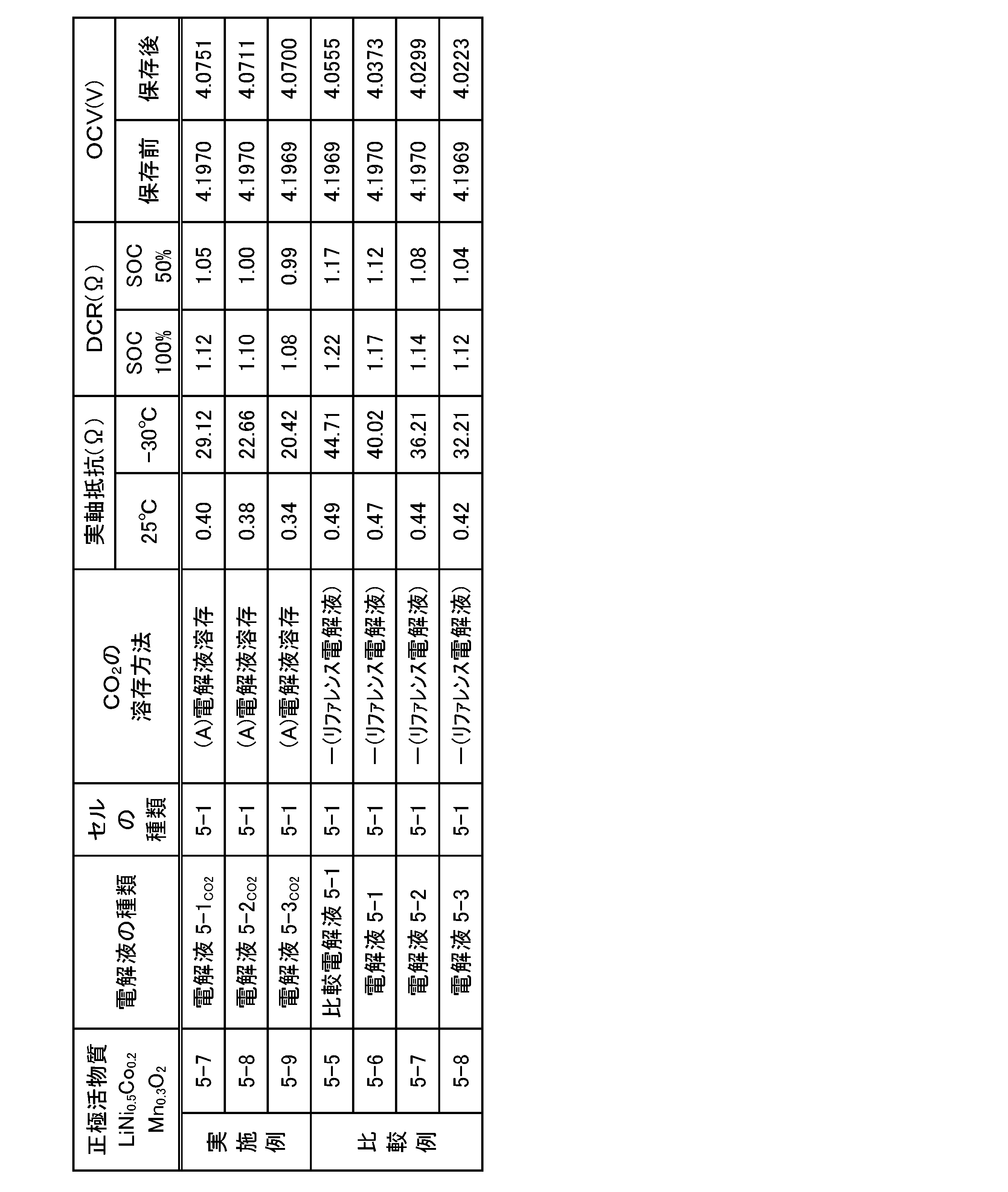

実験例3では、正極活物質として、LiNi1/3Co1/3Mn1/3O2の代わりに市販のLiNi0.6Co0.2Mn0.2O2を用いた。実験例1と同様にして、セルのインピーダンス、DCR及び自己放電(OCV)を測定した。その結果をそれぞれ表5-6に示す。
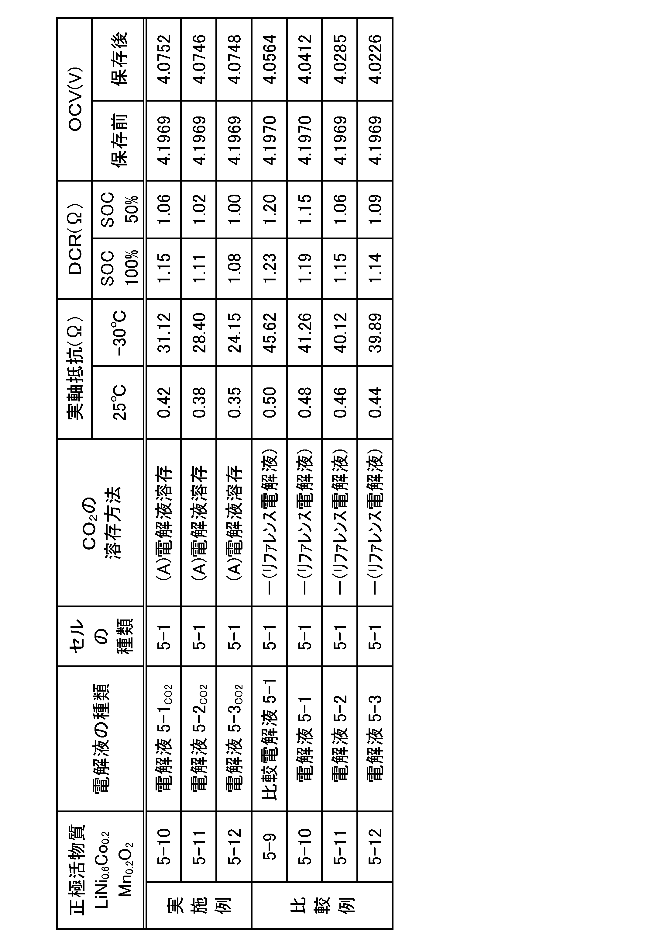
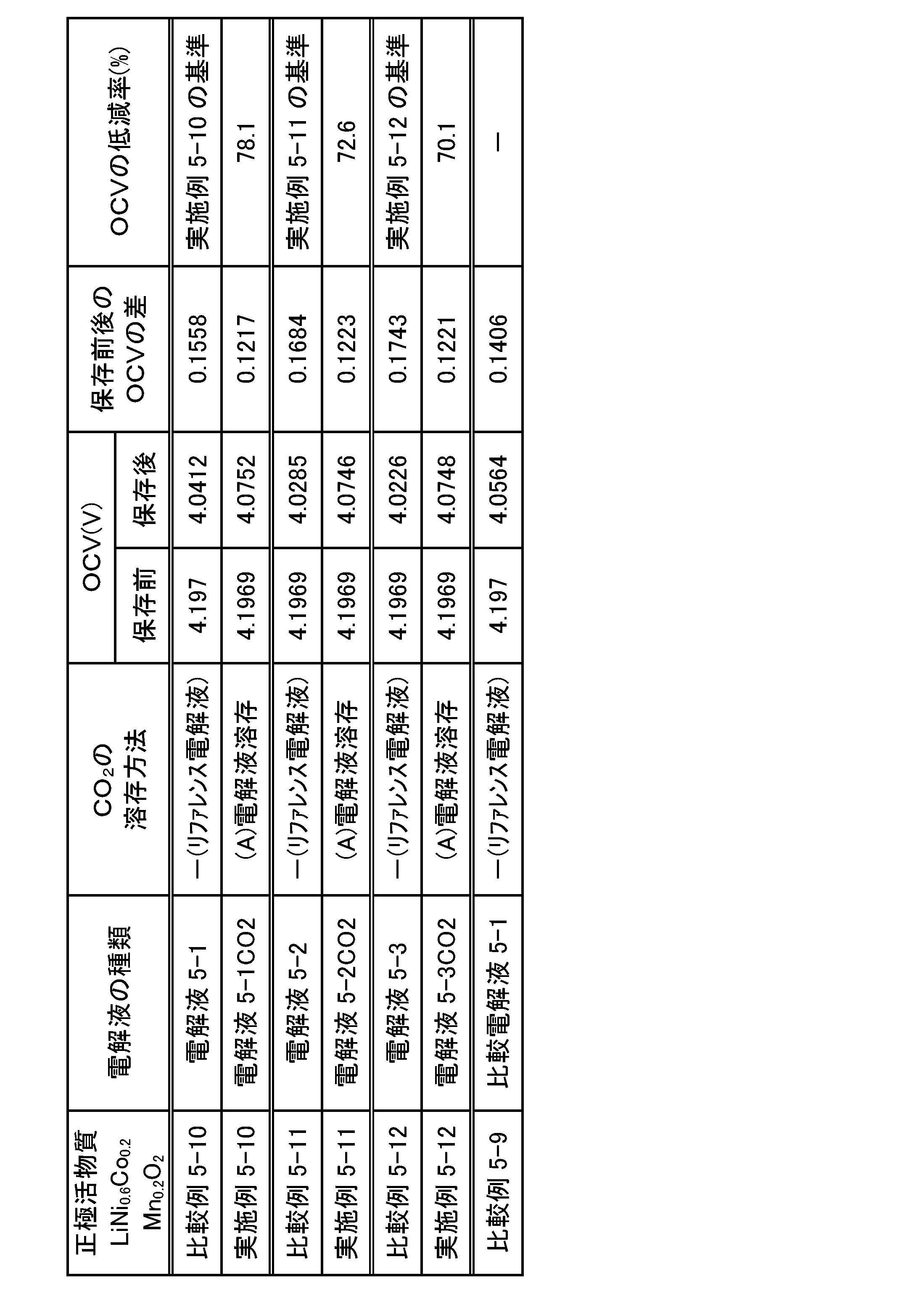
実験例4では、正極活物質として、LiNi1/3Co1/3Mn1/3O2の代わりに市販のLiNi0.8Co0.1Mn0.1O2を用いた。実験例1と同様にして、セルのインピーダンス、DCR及び自己放電(OCV)を測定した。その結果をそれぞれ表5-8に示す。
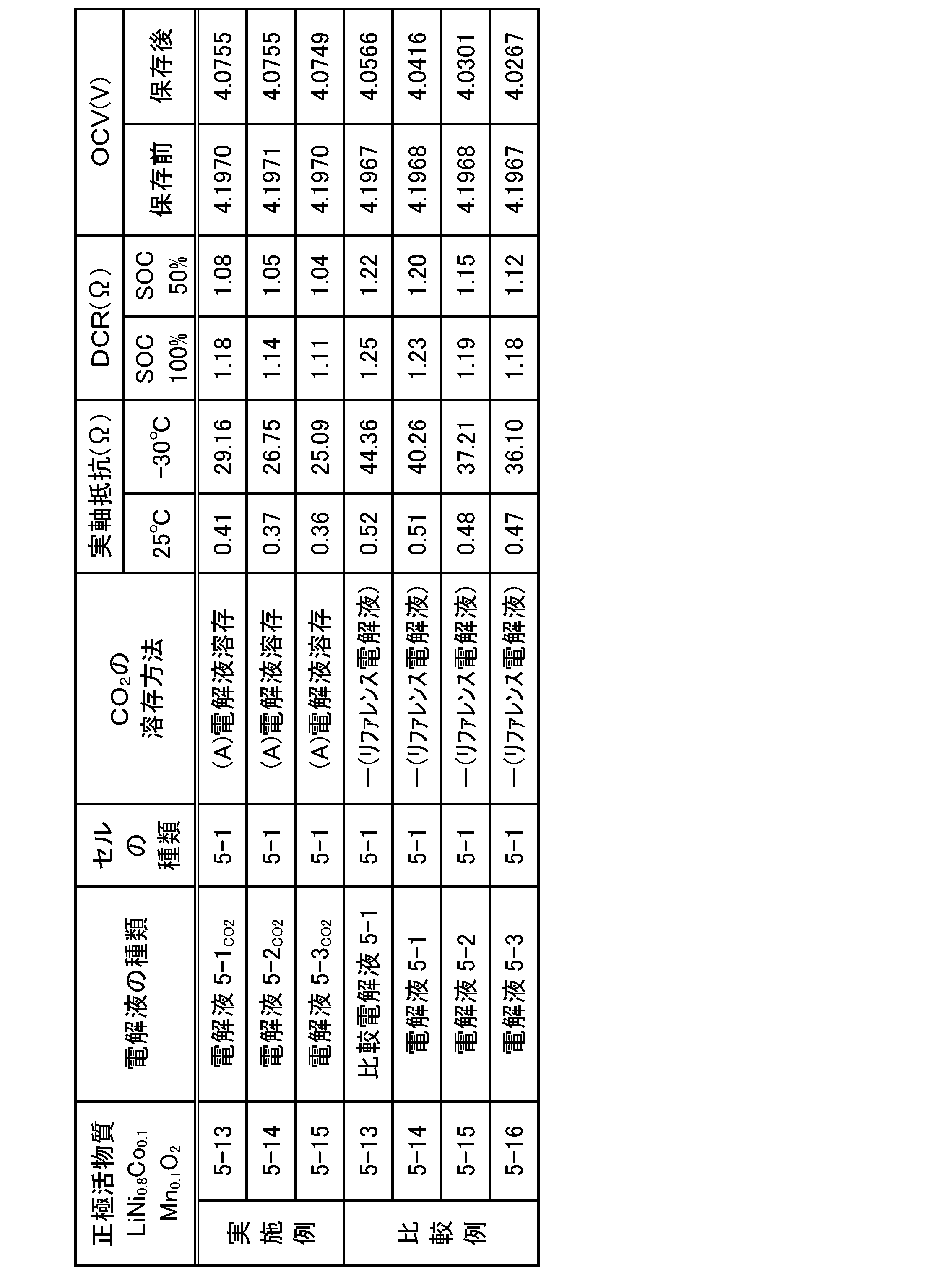
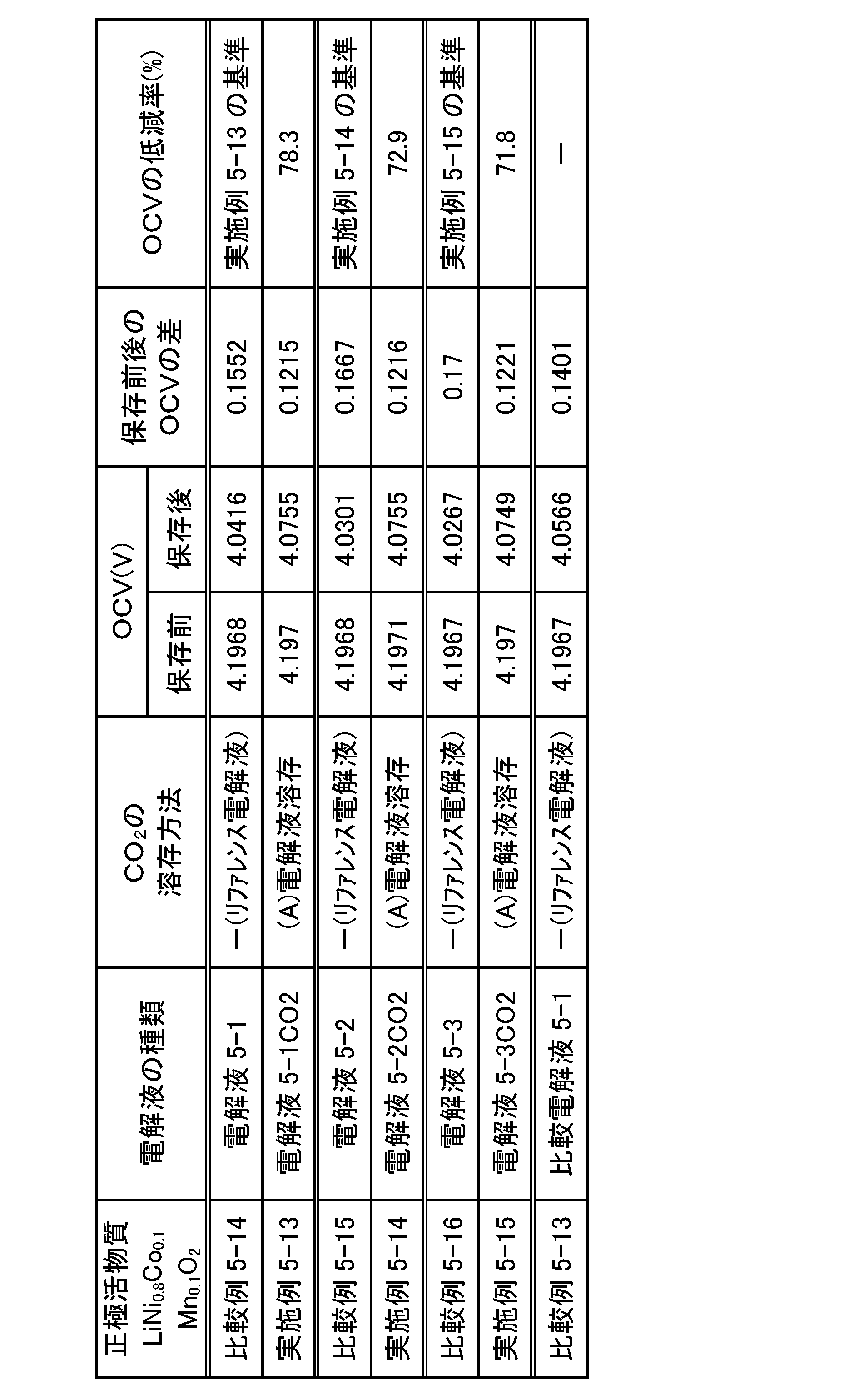
以上の結果より、スルホニルイミド化合物(1)を含む非水電解液と三元系正極活物質(7)を含む正極とを備える電池は、スルホニルイミド化合物(1)の濃度が高くなるほど自己放電が大きくなるものの、当該電解液にさらにCO2等を20質量ppm以上溶存させることで、自己放電を抑制し、LiPF6を単独で含む電解液を用いた電池よりも優れた自己放電抑制の効果が得られることが確認された。また、電池の抵抗値(インピーダンス、DCR)も大幅に低下することが確認された。
(6-1)非水電解液(リファレンス電解液)の調製
LiFSI又はLiPF6のみを含む単体塩組成、並びにLiFSI及びLiPF6を含む混合塩組成の電解質塩を表6-1に記載の濃度で含む電解液に、ジフルオロリン酸リチウム(LiPO2F2)を表6-1に記載の含有量(濃度)となるようにさらに添加したこと以外は、前記「(2-1)非水電解液(リファレンス電解液)の調製」と同様の方法により、非水電解液を調製した。得られた電解液の組成を表6-1に示す。得られたリファレンス電解液をガスクロマトグラフィーで分析し、当該電解液中におけるCO2の溶存量を定量した結果を表6-1の「リファレンス電解液」欄に示す。
前記「(6-1)非水電解液(リファレンス電解液)の調製」で得られた各電解液を用いて、前記「(1-2)CO2が溶存された非水電解液(CO2溶存電解液)の調製(前記(A)の方法、溶存工程:置換工程)」と同様の方法により、CO2溶存電解液を調製し、当該電解液をガスクロマトグラフィーで分析した。CO2溶存電解液中におけるCO2の溶存量を定量した結果を表6-1の「(A)CO2溶存電解液」欄に示す。
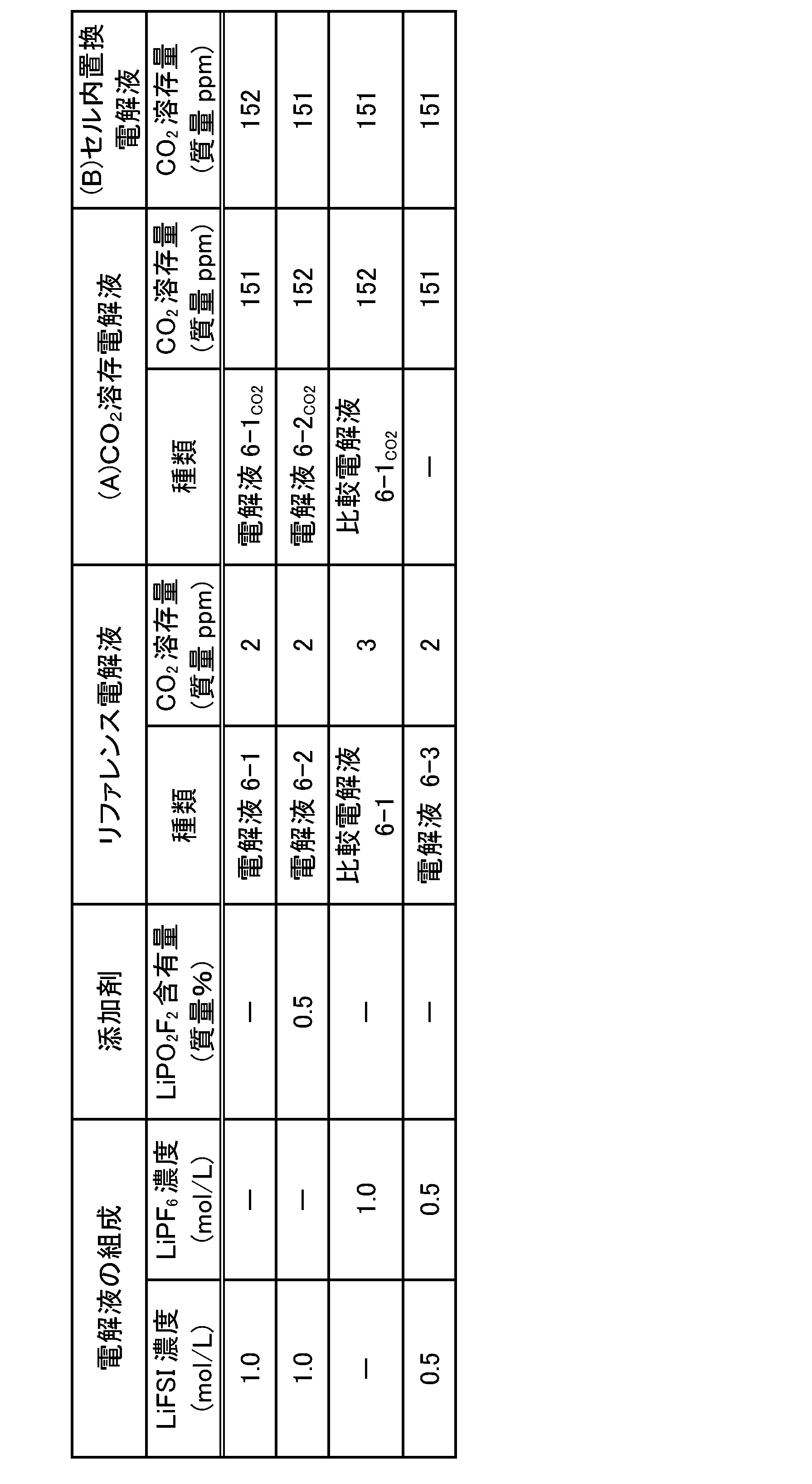
三元系正極活物質(7)であるLiNi1/3Co1/3Mn1/3O2の代わりに市販のリン酸鉄系正極活物質(8)であるLiFePO4を用いたこと以外は、前記「(2-3)ラミネート電池2-1の作製」と同様の方法により、3.55V、容量28.8mAhのラミネート電池(セル)6-1を作製した後、セル6-1のエージング工程を行った。
前記「(2-4)ラミネート電池2-2の作製(前記(B)の方法)」と同様の方法により、3.55V、容量28.8mAhのラミネート電池(セル)6-2を作製した後、セル6-1と同様の手順により、セル6-2のエージング工程を行った。
(インピーダンス及び低温(-20℃)充放電容量)
前記「(2-5)電池の評価」と同様の方法により、セルのインピーダンス及び低温(-20℃)充放電容量を測定した。その結果を表6-2に示す。
エージング後のセルを、常温にて0.5C(14.4mA)、3.55Vで0.02C(0,576mA)終止の定電流定電圧充電を行い、満充電状態とし、60℃で4週間保存し、保存前後のセルの開路電圧(OCV)を測定した。その結果を表6-2に示す。
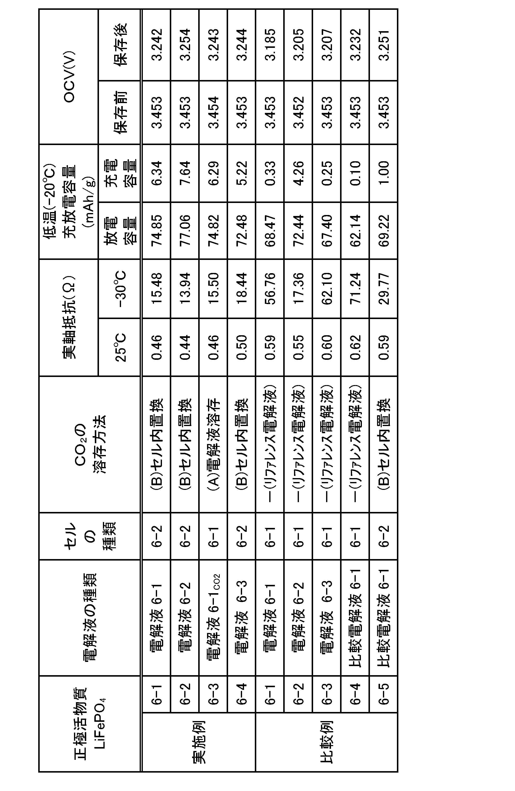
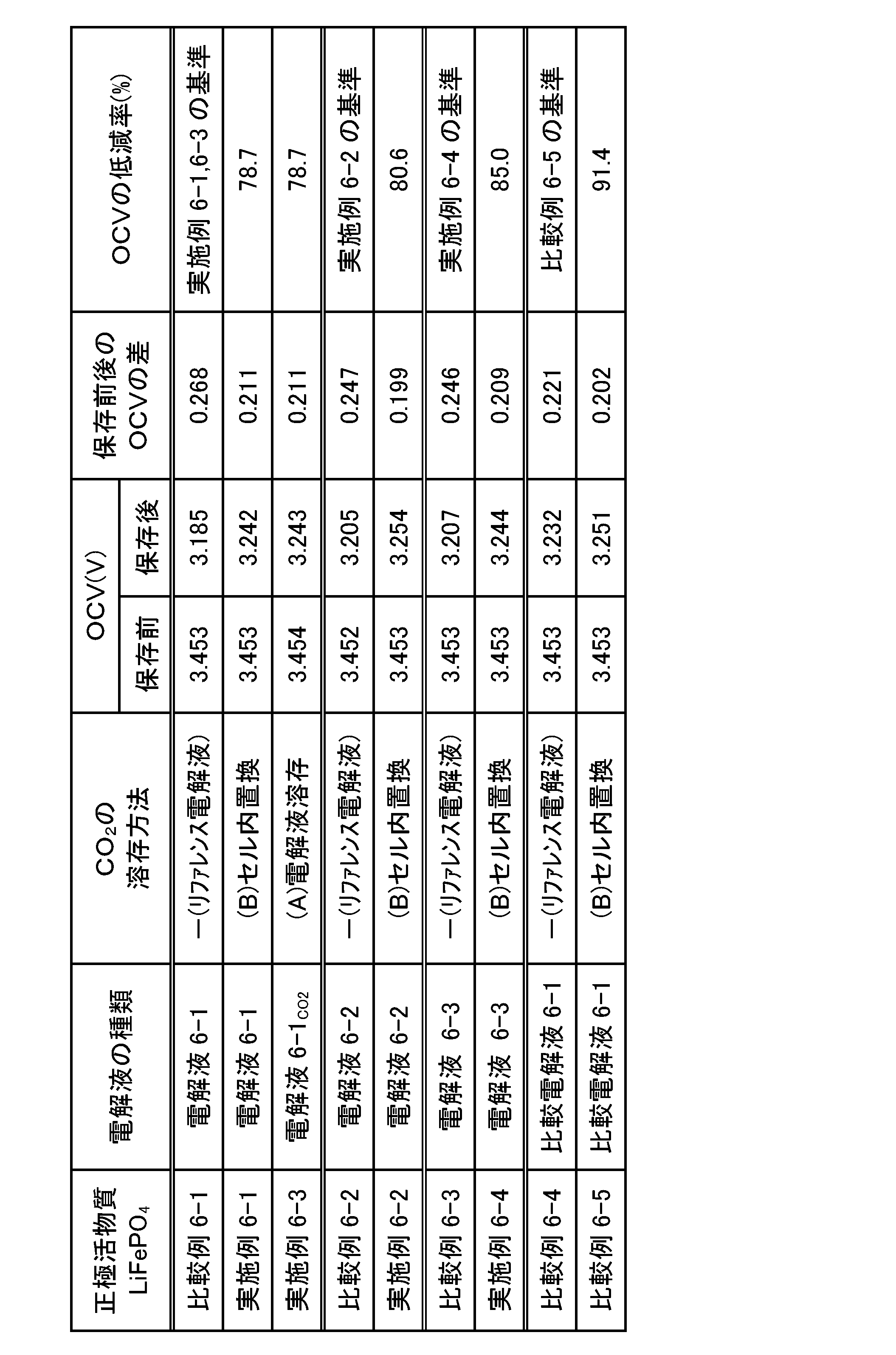
表6-2の結果から、電解液にCO2を溶存又はセル内部の空気をCO2に置換する方法により、CO2を溶存させた電解液を用いた電池はいずれも、意図的にCO2を溶存させていないリファレンス電解液を用いた電池と比較して、インピーダンスが低下した(比較例6-1と実施例6-1,6-3との対比;比較例6-2と実施例6-2との対比;比較例6-3と実施例6-4との対比)。このインピーダンス低下の効果は、特に低温において顕著に表れている。
表6-2の結果から、CO2を溶存させた電解液を用いた電池はいずれも、意図的にCO2を溶存させていないリファレンス電解液を用いた電池と比較して、低温での充放電容量が向上した(対比対象は前記と同じ)。この効果は、インピーダンス測定結果に示した電解液へのCO2溶存による低温でのインピーダンス低下に基づくものと考えられる。
表6-2の結果から、CO2を溶存させた電解液を用いた電池はいずれも、意図的にCO2を溶存させていないリファレンス電解液を用いた電池と比較して、保存後のOCVの低下度が小さく、電池の自己放電が抑制されることが分かった(対比対象は前記と同じ)。
以上の結果より、スルホニルイミド化合物(1)を含む非水電解液を備える電池において、電池の作動電圧が、三元系正極活物質(7)を含む正極を備えるものとは異なるリン酸鉄系正極活物質(8)を含む正極を備えるものでも、当該非水電解液にCO2等を20質量ppm以上溶存させることにより、電池の自己放電が抑制されるという効果が明確に確認された。また、CO2等の溶存とLiPO2F2の添加との相乗効果により、電池の抵抗(インピーダンス)の低下や低温充放電特性の向上等の点で、電池性能がさらに改善することが確認された。
(7-1)非水電解液(リファレンス電解液)の調製
電解液溶媒としてジメチルカーボネート(DMC)(キシダ化学(株)製)に、LiFSIのみを含む単体塩組成の電解質塩を表7-1に示す濃度となるように溶解することにより、非水電解液を調製した。また、電解液溶媒としてEC:EMC=3:7(体積比)組成の混合溶媒に、LiPF6のみを含む単体塩組成の電解質塩を表7-1に示す濃度となるように溶解することにより、非水電解液を調製した。得られた各電解液の組成を表7-1に示す。得られたリファレンス電解液をガスクロマトグラフィーで分析し、当該電解液中におけるCO2の溶存量を定量した結果を表7-1の「リファレンス電解液」欄に示す。
電解液溶媒として用いたDMC、表7-1に示す参考電解液7-1及び電解液7-1、並びにLiFSI粉末について、NRS-3100(日本分光社製)を使用してラマン分光測定を行った。その結果を図1に示す。なお、図1において、横軸は波数(cm-1)であり、縦軸は散乱強度である。
・装置:JASCO RFT-6000(日本分光社製)
・レーザー波長:1064nm
・露光時間:10秒×5回
・中心波数:1450cm-1
・スリット:φ0.05mm
・減光器:オープン
・対物レンズ:20倍
・データ間隔:4cm-1
・スムージング処理:ベースライン補正(872cm-1~1873cm-1の間で直線補正)
・スムージング処理、単純平均移動(コンボリューション幅:5)
・測定セル:ガラスセル
・不活性ガス雰囲気下で電解液をガラスセルに密閉し、測定に供した。
前記「(7-1)非水電解液(リファレンス電解液)の調製」で得られた各電解液を用いて、前記「(1-2)CO2が溶存された非水電解液(CO2溶存電解液)の調製(前記(A)の方法、溶存工程:置換工程)」と同様の方法により、CO2溶存電解液を調製し、当該電解液をガスクロマトグラフィーで分析した。CO2溶存電解液中におけるCO2の溶存量を定量した結果を表7-1の「(A)CO2溶存電解液」欄に示す。
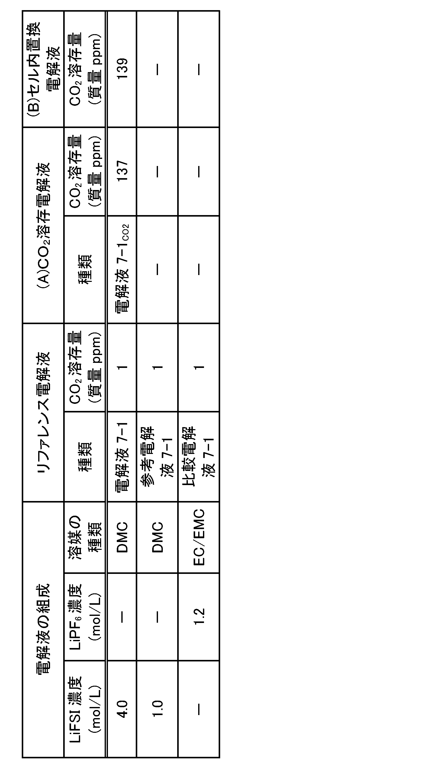
前記「(2-3)ラミネート電池2-1の作製」と同様の方法により、4.2V、容量32mAhのラミネート電池(セル)7-1を作製した後、セル7-1のエージング工程を行った。
前記「(2-4)ラミネート電池2-2の作製(前記(B)の方法)」と同様の方法により、4.2V、容量32mAhのラミネート電池(セル)7-2を作製した後、セル7-1と同様の手順により、セル7-2のエージング工程を行った。
(インピーダンス)
前記「(2-5)電池の評価」と同様の方法により、セルのインピーダンスを測定した。その結果を表7-2に示す。
エージング後のセルを、常温にて0.5C(16mA)、4.2Vで0.02C(0,64mA)終止の定電流定電圧充電を行い、満充電状態とし、60℃で4週間保存し、保存前後のセルの開路電圧(OCV)を測定した。その結果を表7-2に示す。
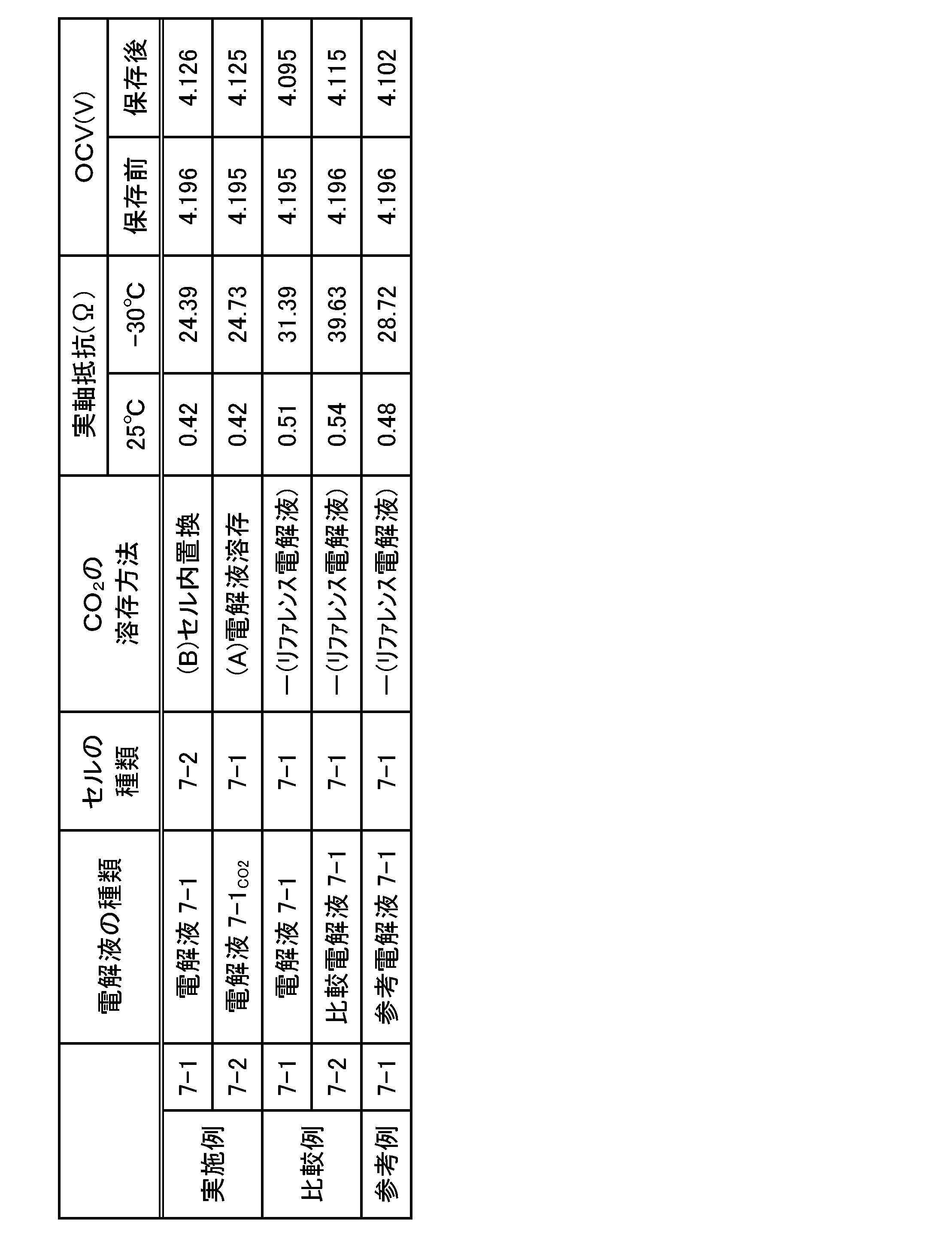
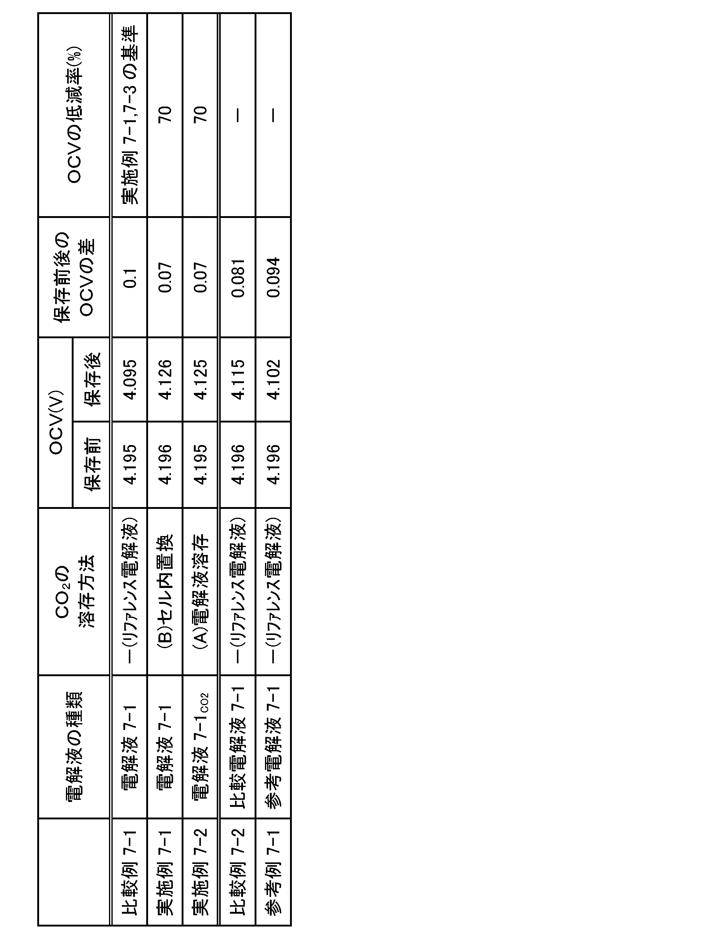
表7-2の結果から、電解液にCO2を溶存又はセル内部の空気をCO2に置換する方法により、CO2を溶存させた電解液を用いた電池はいずれも、意図的にCO2を溶存させていないリファレンス電解液を用いた電池と比較して、インピーダンスが低下した(参考例7-1と実施例7-1,7-2の対比)。このインピーダンス低下の効果は、特に低温において顕著に表れている。
表7-2及び表7-3の結果から、CO2を溶存させた電解液を用いた電池はいずれも、意図的にCO2を溶存させていないリファレンス電解液を用いた電池と比較して、保存後のOCVの低下度が小さく、電池の自己放電が抑制されることが分かった(参考例7-1と実施例7-1,7-2の対比)。
以上の結果より、スルホニルイミド化合物(1)を含む非水電解液において、ラマンスペクトルにおける2つのピーク強度の関係がIs>Ioであるものでも、当該電解液にCO2等を20質量ppm以上溶存させることにより、電池の自己放電に関して明確な効果が確認された。
(8-1)非水電解液(リファレンス電解液)の調製
電解液溶媒としてEC:EMC=3:7(体積比)組成の混合溶媒に、LiFSI及びLiPF6を含む混合塩組成の電解質塩、又はLiPF6のみを含む単体塩組成の電解質塩をそれぞれ表8-1に示す濃度となるように溶解し、さらにフルオロエチレンカーボネート(FEC、キシダ化学(株)製、以下同じ)を10質量%加えることにより、非水電解液を調製した。得られた電解液の組成を表8-1に示す。得られたリファレンス電解液をガスクロマトグラフィーで分析し、当該電解液中におけるCO2の溶存量を定量した結果を表8-1の「リファレンス電解液」欄に示す。
前記「(8-1)非水電解液(リファレンス電解液)の調製」で得られた各電解液を用いて、前記「(1-2)CO2が溶存された非水電解液(CO2溶存電解液)の調製(前記(A)の方法、溶存工程:置換工程)」と同様の方法により、CO2溶存電解液を調製し、当該電解液をガスクロマトグラフィーで分析した。CO2溶存電解液中におけるCO2の溶存量を定量した結果を表8-1の「(A)CO2溶存電解液」欄に示す。
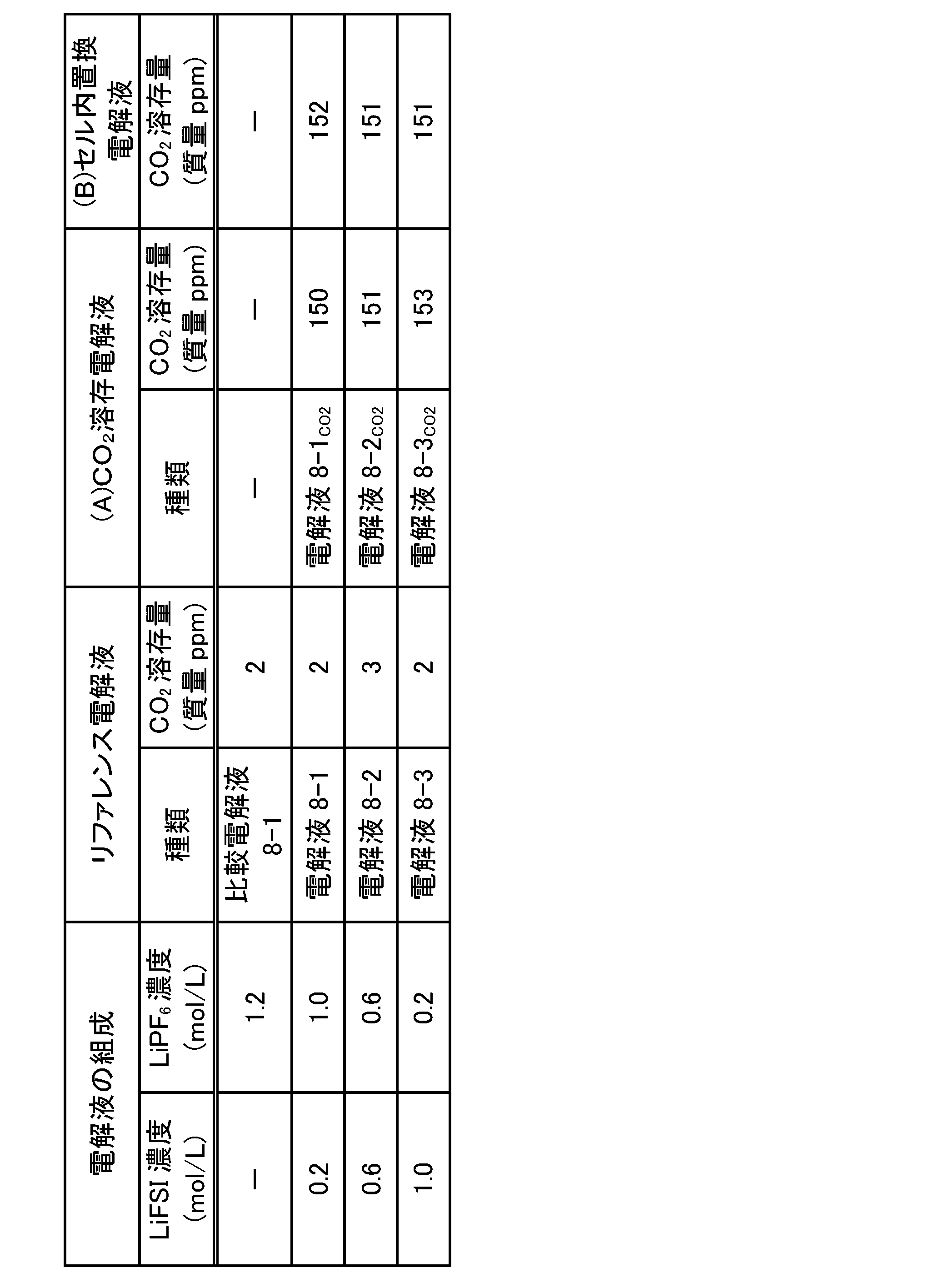
(Si含有黒鉛合材シートの作製)
活物質としてSi含有グラファイト(SiO:グラファイト=10:90)、導電助剤としてカーボンブラック(デンカ(株)製、製品名:デンカブラック)及び炭素繊維(昭和電工(株)製、製品名:VGCF)、スチレン-ブタジエンゴム(SBR、結着剤)及びカルボキシメチルセルロース(CMC、結着剤)を、超純水中に分散させて、Si含有黒鉛合材スラリー(活物質:導電助剤:SBR:CMC=100:5:3:1(固形分質量比))を作製した。続いて、得られた合材スラリーを銅箔(集電体、福田金属箔粉工業(株)製、厚み15μm)に対して、乾燥後の塗工重量が7.2mg/cm2となるようにアプリケーターで片面塗工し、80℃のホットプレート上で10分間乾燥させた。さらに、100℃の真空乾燥炉で12時間乾燥させた。その後、ロールプレス機により密度1.5g/cm3となるまで加圧成形することにより、厚み65μmのSi含有黒鉛合材シートを得た。
CR2032コイン型電池用部品(宝泉(株)製)を用いて、コイン型リチウム電池を組み立てた。ガスケットを装着した負極キャップ、ウェーブワッシャー、スペーサー、及びリチウム箔(φ14mm、厚み0.5mm)(本城金属(株)製)を、この順に重ねた後、表8-1に示す非水電解液25μLをリチウム箔上に滴下した。リチウム箔上にPEセパレータを重ねた後、再び非水電解液25μLをセパレータに滴下して含浸させた後、前記で作製したSi含有黒鉛合材シートを円形に打ち抜いたもの(φ14mm)を、セパレータを挟んでリチウム箔と対向するように配置した。その上に正極ケースを重ね、カシメ機でかしめることによりコイン型リチウム電池8-1を作製した。
内部の空気がCO2で置換されたグローブボックス内で電池の作製を行ったこと以外は前記(コイン型リチウム電池の作製)と同様の方法により、コイン型リチウム電池8-2を作製し、エージング工程を行った。
エージング後のコイン型リチウム電池8-1及び8-2を、常温にて1.5V、0.1C(0.5mA)でCC放電を行った後、アルゴンガスで置換されたグローブボックス内で解体して電解液を抜き取った。抜き取った電解液をガスクロマトグラフィーで分析し、当該電解液中におけるCO2の溶存量を定量した。定量結果を表8-2の「エージング後のCO2溶存量」欄に示す。
(自己放電)
エージング後のコイン型リチウム電池を、1.5V、0.1C(0.5mA)でCC放電を行ったのち、常温にて0.01V、0.1C(0.5mA)でCCCV充電を行い、満充電とした。この時の充電容量を保存前の充電容量とした。満充電状態の電池を60℃で4週間保存し、保存後の電池を常温で2時間放冷した後、1.5V、0.1C(0.5mA)でCC放電を行い、この時の放電容量を残存容量とした。その結果を表8-2に示す。なお、保存前の充電容量と残存容量の差(以下、実施例8シリーズにおいて「自己放電容量」という)が小さいほど、電池の自己放電が抑制されていることを意味する。
エージング後のセルを、常温にて0.1C(0.5mA)で1.5Vまで放電後、常温にて0.5C(2.5mA)で1時間の定電流充電をして充電深度(SOC)50%にしたこと以外は、前記「(1-5)電池の評価」の(インピーダンス)の欄に記載の方法と同様にして、実軸抵抗(界面抵抗)を求めた。その結果を表8-2に示す。
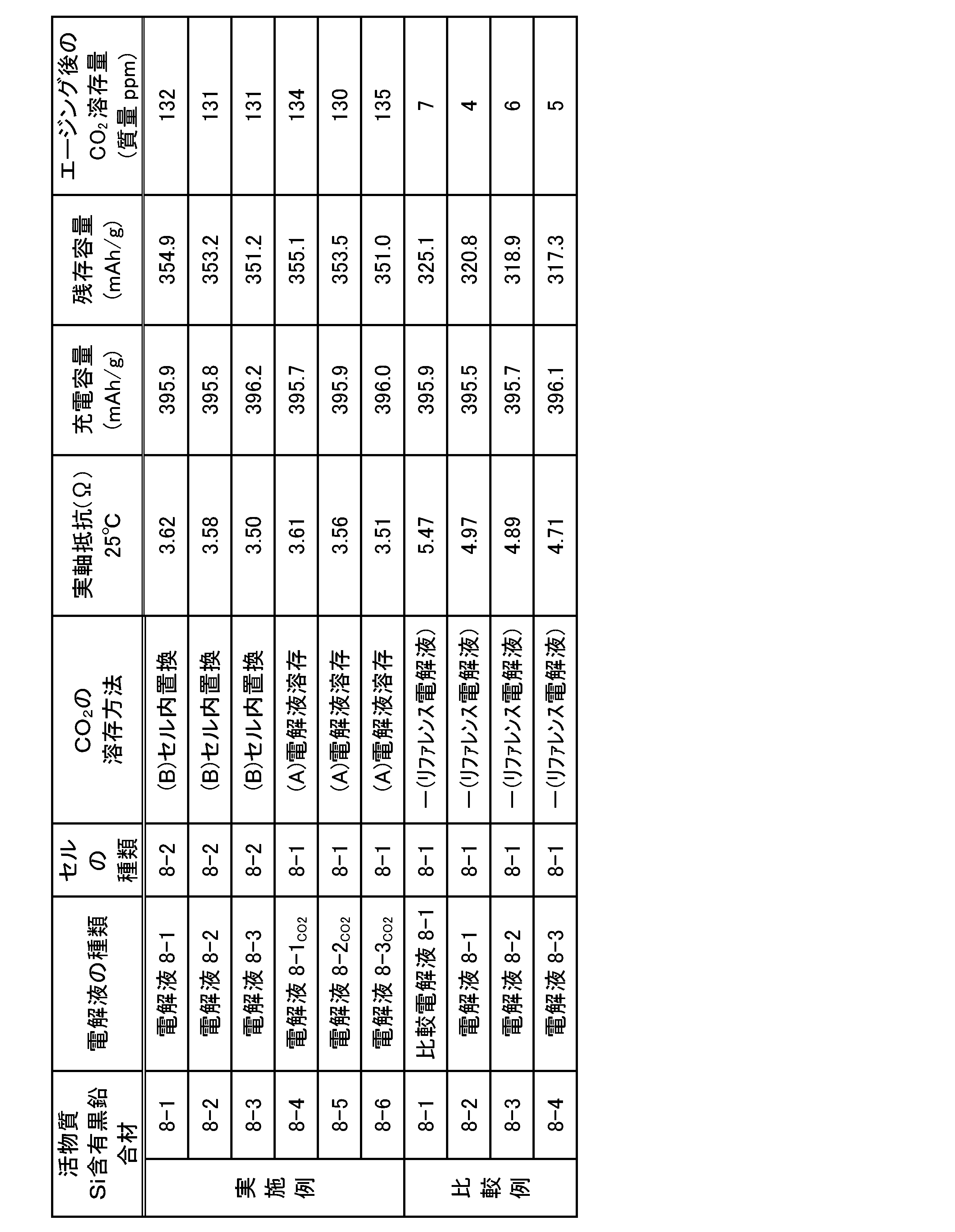
[数3]
実施例8-1の自己放電容量の低減率(%)=[{(実施例8-1の保存前の放電容量)-(実施例8-1の保存後の放電容量)}/{(比較例8-2の保存前の放電容量)-(比較例8-2の保存後の放電容量)}]×100 (3)
により求めることができる。なお、自己放電容量の低減率は、その値が小さいほど、電池の自己放電が抑制されている、即ち、自己放電抑制の効果に優れる(自己放電抑制の効果(程度)が高い)ことを意味する。
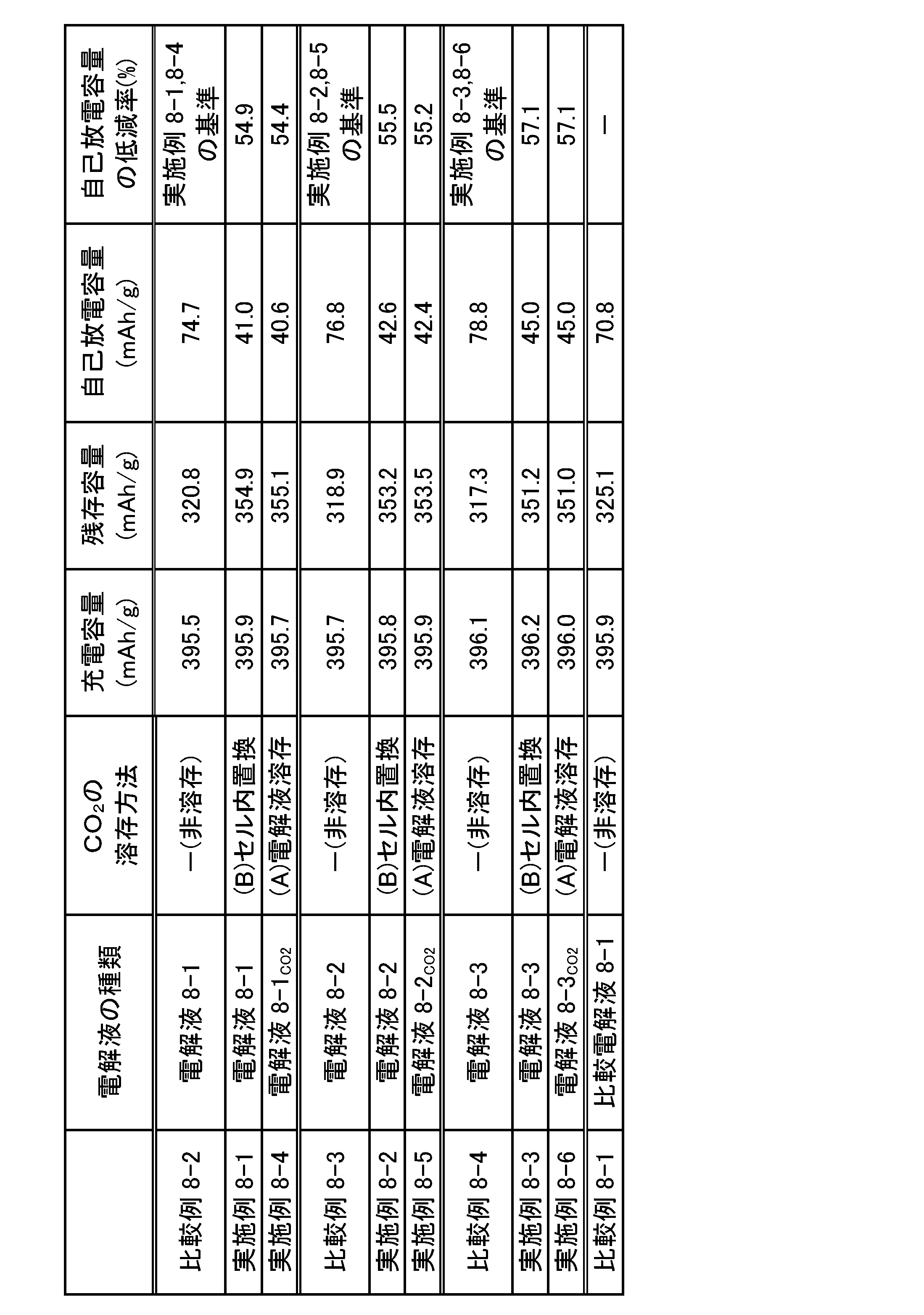
表8-2の結果から、電解液にCO2を溶存又は電池内部の空気をCO2に置換する方法により、CO2を溶存させた電解液を用いた電池はいずれも、意図的にCO2を溶存させていないリファレンス電解液を用いた電池と比較して、インピーダンスが大幅に低下した(比較例8-2と実施例8-1,8-4との対比;比較例8-3と実施例8-2,8-5との対比;比較例8-4と実施例8-3,8-6との対比)。このインピーダンス低下の効果は、特に低温において顕著に表れている。
表8-3の結果から、電解液にCO2を溶存又は電池内部の空気をCO2に置換する方法により、CO2を溶存させた電解液を用いた電池はいずれも、意図的にCO2を溶存させていないリファレンス電解液を用いた電池と比較して、保存後の残存容量が大きく、電池の自己放電が抑制されることが分かった(対比対象は前記と同じ)。また、実施例8-1~8-6の電池では、電解液にLiFSIが含まれているにもかかわらず、LiPF6を単独で含む電解液を用いた電池(比較例8-1)と比較して、保存後の残存容量が大きく、優れた自己放電抑制の効果が得られることが分かった。さらに、表8-3の結果から、LiFSI及びSi含有黒鉛合材を含む電池では、LiFSIとLiPF6との混合比率によって自己放電容量の低減率をさらに低減できることが分かった。
以上の結果より、スルホニルイミド化合物(1)及び常温での蒸気圧が1kPa以上である電解液溶媒(EMC、鎖状炭酸エステル)を含む非水電解液を含む非水電解液と、Si又はその酸化物及び黒鉛を含む極板とを備える電池は、スルホニルイミド化合物(1)の濃度が高くなるほど自己放電が大きくなるものの、当該電解液にさらにCO2等を20ppm以上溶存させることで、自己放電を抑制し、LiPF6を単独で含む電解液を用いた電池よりも優れた自己放電抑制の効果が得られることが確認された。また、電池の抵抗値(インピーダンス)も大幅に低下することが確認された。
(9-1)非水電解液(リファレンス電解液)の調製
電解液溶媒としてエチレンカーボネート(EC)及び/又はプロピレンカーボネート(PC)と、ジメチルカーボネート(DMC)、エチルメチルカーボネート(EMC)、ジエチルカーボネート(DEC)及びγ―ブチロラクトン(GBL)(すべてキシダ化学(株)製)の少なくとも一種とを使用したこと以外は、前記「(1-1)非水電解液(リファレンス電解液)の調製」と同様の方法により、非水電解液を調製した。得られた電解液の組成を表9-1に示す。得られたリファレンス電解液をガスクロマトグラフィーで分析し、当該電解液中におけるCO2の溶存量を定量した結果を表9-1の「リファレンス電解液」欄に示す。
前記「(9-1)非水電解液(リファレンス電解液)の調製」で得られた各電解液を用いて、前記「(1-2)CO2が溶存された非水電解液(CO2溶存電解液)の調製(前記(A)の方法、溶存工程:置換工程)」と同様の方法により、CO2溶存電解液を調製し、当該電解液をガスクロマトグラフィーで分析した。CO2溶存電解液中におけるCO2の溶存量を定量した結果を表9-1の「(A)CO2溶存電解液」欄に示す。

前記「(2-3)ラミネート電池2-1の作製」と同様の方法により、4.2V、容量32mAhのラミネート電池(セル)9-1を作製した後、セル9-1のエージング工程を行った。
前記「(2-4)ラミネート電池2-2の作製(前記(B)の方法)」と同様の方法により、4.2V、容量32mAhのラミネート電池(セル)9-2を作製した後、セル9-1と同様の手順により、セル9-2のエージング工程を行った。
(インピーダンス、DCR、低温充放電特性及び自己放電)
前記「(1-5)電池の評価」と同様の方法により、セルのインピーダンス、DCR、低温(-20℃)充放電容量及び自己放電(OCV)を測定した。その結果を表9-2に示す。
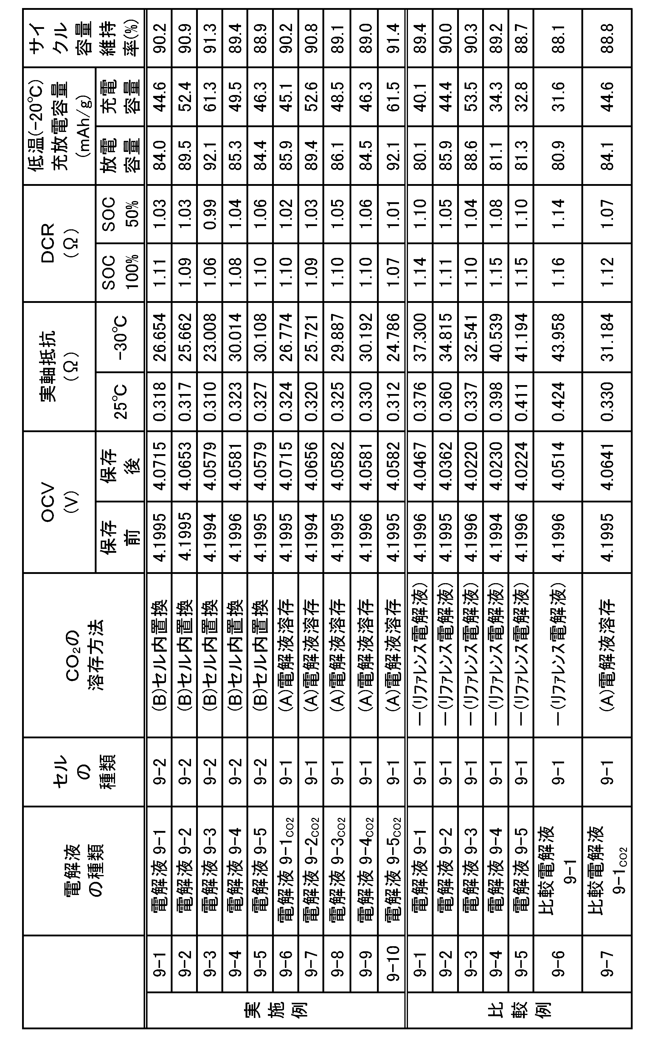

表9-2の結果から、電解液にCO2を溶存又はセル内部の空気をCO2に置換する方法により、CO2を溶存させた電解液を用いた電池はいずれも、意図的にCO2を溶存させていないリファレンス電解液を用いた電池と比較して、インピーダンスが低下した(比較例9-1と実施例9-1,び9-6との対比;比較例9-2と実施例9-2,9-7との対比;比較例9-3と実施例9-3,9-8との対比;比較例9-4と実施例9-4,9-9との対比、比較例9-5と実施例9-5,9-10との対比)。このインピーダンス低下の効果は、特に低温において顕著に表れている。
表9-2の結果から、CO2を溶存させた電解液を用いた電池はいずれも、意図的にCO2を溶存させていないリファレンス電解液を用いた電池と比較して、低温での充放電容量が向上した(対比は前記と同じ)。この効果は、インピーダンス測定結果に示した電解液へのCO2溶存による低温でのインピーダンス低下に基づくものと考えられる。
表9-2の結果から、CO2を溶存させた電解液を用いた電池はいずれも、意図的にCO2を溶存させていないリファレンス電解液を用いた電池と比較して、保存後のOCVの低下度が小さく、電池の自己放電が抑制されることが分かった(対比対象は前記と同じ)。また、表9-3の結果から、LiFSIを含み且つCO2を溶存させた電解液を用いた電池(各実施例)はいずれも、LiFSIの代わりにLiPF6を単独で含む電解液を用いた電池(比較例9-6)と比較して、OCVの低減率が小さいため、自己放電がより一層抑制されることが分かった。
以上の結果より、スルホニルイミド化合物(1)を含む非水電解液において、電解液溶媒として鎖状カーボネート又はラクトンを含む場合でも、CO2等を20ppm以上溶存させることにより、電池の自己放電に関して明確な効果が確認された。
(10-1)非水電解液(リファレンス電解液)の調製
電解液溶媒としてエチレンカーボネート(EC)(キシダ化学(株)製)、エチルメチルカーボネート(EMC)(キシダ化学(株)製)、1-エチル-3-メチルイミダゾリウムビス(フルオロスルホニル)イミド(EMImFSI)(日本触媒(株)製)、1-メチル-1-プロピルピロリジニウムビス(フルオロスルホニル)イミド(P13FSI)(東京化成(株)製)を使用したこと以外は、前記「(1-1)非水電解液(リファレンス電解液)の調製」と同様の方法により、非水電解液を調製した。得られた電解液の組成を表10-1に示す。得られたリファレンス電解液をガスクロマトグラフィーで分析し、当該電解液中におけるCO2の溶存量を定量した結果を表10-1の「リファレンス電解液」欄に示す。
前記「(10-1)非水電解液(リファレンス電解液)の調製」で得られた各電解液を用いて、前記「(1-2)CO2が溶存された非水電解液(CO2溶存電解液)の調製(前記(A)の方法、溶存工程:置換工程)」と同様の方法により、CO2溶存電解液を調製し、当該電解液をガスクロマトグラフィーで分析した。CO2溶存電解液中におけるCO2の溶存量を定量した結果を表10-1の「(A)CO2溶存電解液」欄に示す。
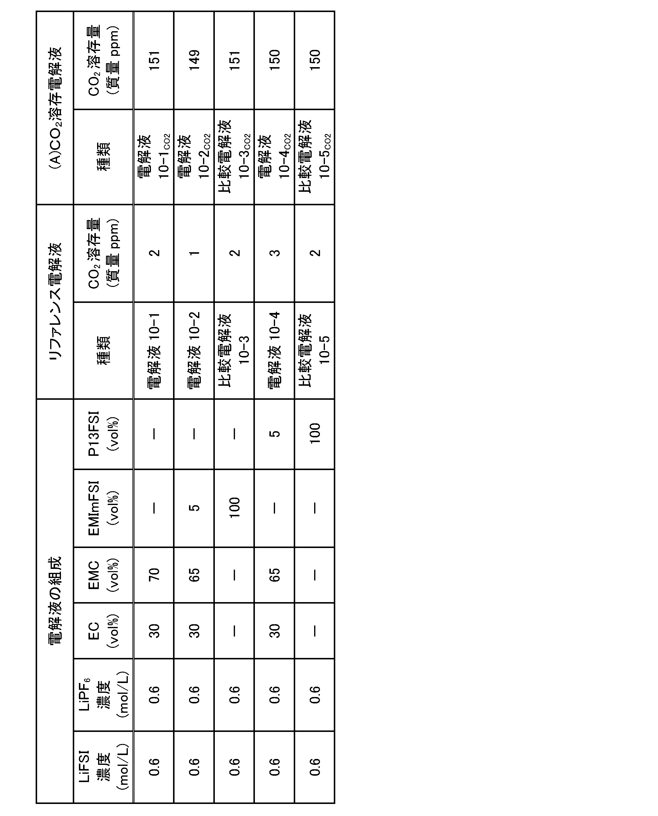
厚み22μmのセルロースシートを6枚重ねてセパレータとした以外は前記「(2-3)ラミネート電池2-1の作製」と同様の方法により、4.2V、容量32mAhのラミネート電池(セル)10-1を作製した。
(初回放電容量)
前記で得られたセル10-1を、充放電試験装置を用い、常温(25℃、以下同じ)にて0.1C(3mA)で4時間の定電流充電を行い、5日間常温で放置した。放置後、余剰ラミネートを開裂し、真空封止することでセル10-1内のガス抜きを行った。常温にて4.2V、0.5C(15mA)で5時間の定電流定電圧(CCCV)充電をした後、常温にて0.2C(6mA)、2.75V終止(放電終止電圧)の定電流放電を行い、初回放電容量を評価した。その結果を表10-2に示す。
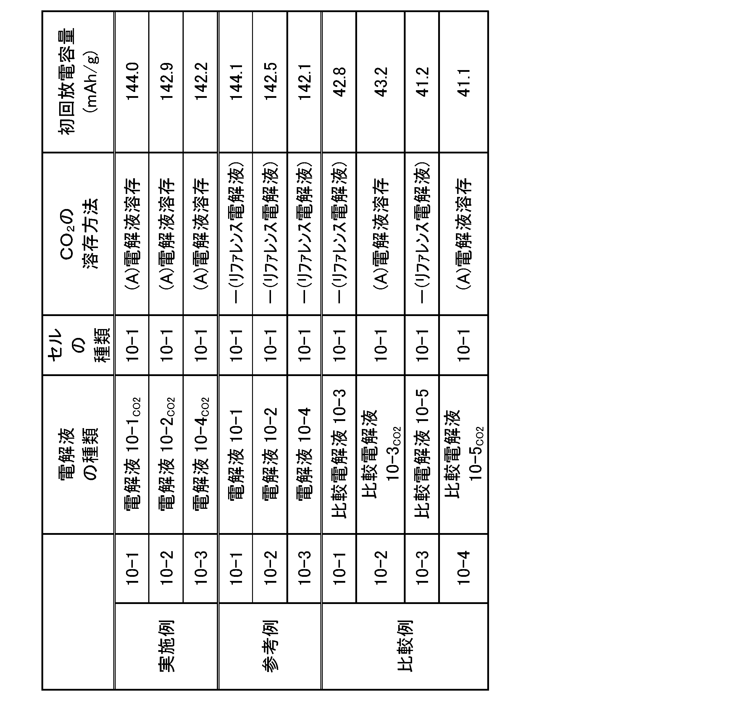
表10-2の結果から、ECやEMCを含まない電解液を用いた電池はいずれも、ECやEMCを含む電解液を用いた電池と比較して初回放電容量が著しく低下した。これはCO2を溶存させた電解液でも同様であり、実施例シリーズ1~9で述べてきたCO2の性能改善よりも大きな差であることから、総合的に電池性能が低下したといえる。この現象はEMImFSIやP13FSIの持つ高い粘度によって電解液の抵抗が増大したことによると考えられる。
Claims (12)
- 電解質塩として一般式(1)で表されるスルホニルイミド化合物と、電解液溶媒とを含み、且つ二酸化炭素(CO2)、一酸化炭素(CO)、炭酸水素イオン(HCO3 -)及び炭酸イオン(CO3 2-)の少なくとも一種を溶存している非水電解液であって、
前記電解液溶媒は、カーボネート系溶媒、ラクトン系溶媒、エーテル系溶媒、ニトリル系溶媒及び鎖状エステル系溶媒からなる群より選択される少なくとも一種を含み、
前記二酸化炭素(CO2)、一酸化炭素(CO)、炭酸水素イオン(HCO3 -)及び炭酸イオン(CO3 2-)の少なくとも一種の合計溶存量が20質量ppm以上である、非水電解液。
LiN(R1SO2)(R2SO2) (R1及びR2は同一又は異なってフッ素原子、炭素数1~6のアルキル基又は炭素数1~6のフルオロアルキル基を示す。) (1) - 前記一般式(1)で表されるスルホニルイミド化合物が、LiN(FSO2)2及びLiN(CF3SO2)2の少なくとも一種を含む、請求項1に記載の非水電解液。
- 前記非水電解液の振動分光スペクトルにおける前記電解液溶媒由来のピーク強度につき、該電解液溶媒本来のピークの強度をIoとし、該ピークがシフトしたときのピークの強度をIsとした場合、Is>Ioである、請求項1又は2に記載の非水電解液。
- 前記電解質塩が、一般式(2)で表される化合物、一般式(3)で表される化合物及びLiAsF6からなる群より選択される少なくとも一種をさらに含む、請求項1~3のいずれか一項に記載の非水電解液。
LiPFa(CmF2m+1)6-a (a:0≦a≦6、m:1≦m≦4) (2)
LiBFb(CnF2n+1)4-b (b:0≦b≦4、n:1≦n≦4) (3) - 一般式(4)で表される化合物、一般式(5)で表される化合物及び一般式(6)で表される化合物からなる群より選択される少なくとも一種をさらに含む、請求項1~4のいずれか一項に記載の非水電解液。
M1POcFd (M1:アルカリ金属元素、c:1≦c≦3、d:1≦d≦3) (4)
M2(FSO3)e (M2:1価又は2価の金属元素、e:1又は2) (5)

- 電解質塩として一般式(1)で表されるスルホニルイミド化合物と、電解液溶媒とを含み、且つ二酸化炭素(CO2)、一酸化炭素(CO)、炭酸水素イオン(HCO3 -)及び炭酸イオン(CO3 2-)の少なくとも一種が溶存している非水電解液を製造する方法であって、
前記電解液溶媒は、カーボネート系溶媒、ラクトン系溶媒、エーテル系溶媒、ニトリル系溶媒及び鎖状エステル系溶媒からなる群より選択される少なくとも一種を含み、
前記二酸化炭素(CO2)、一酸化炭素(CO)、炭酸水素イオン(HCO3 -)及び炭酸イオン(CO3 2-)の少なくとも一種を非水電解液中に溶存させる溶存工程を備え、
前記溶存工程は、前記二酸化炭素(CO2)、一酸化炭素(CO)、炭酸水素イオン(HCO3 -)及び炭酸イオン(CO3 2-)の少なくとも一種を含むガスを非水電解液に加圧する加圧工程、該ガスを非水電解液に接触させる接液工程、該ガスを非水電解液に吹き込むバブリング工程及び非水電解液を入れた密閉容器内の空気を該ガスに置換する置換工程の少なくとも一つを含む、非水電解液の製造方法。
LiN(R1SO2)(R2SO2) (R1及びR2は同一又は異なってフッ素原子、炭素数1~6のアルキル基又は炭素数1~6のフルオロアルキル基を示す。) (1) - 正極、負極及び非水電解液を備えた二次電池であって、
前記非水電解液は、電解質塩として一般式(1)で表されるスルホニルイミド化合物と、電解液溶媒としてカーボネート系溶媒、ラクトン系溶媒、エーテル系溶媒、ニトリル系溶媒及び鎖状エステル系溶媒からなる群より選択される少なくとも一種とを含み、且つ二酸化炭素(CO2)、一酸化炭素(CO)、炭酸水素イオン(HCO3 -)及び炭酸イオン(CO3 2-)の少なくとも一種を溶存しており、前記二酸化炭素(CO2)、一酸化炭素(CO)、炭酸水素イオン(HCO3 -)及び炭酸イオン(CO3 2-)の少なくとも一種の合計溶存量が20質量ppm以上である、二次電池。
LiN(R1SO2)(R2SO2) (R1及びR2は同一又は異なってフッ素原子、炭素数1~6のアルキル基又は炭素数1~6のフルオロアルキル基を示す。) (1) - 前記正極は、一般式(7)で表される正極活物質及び一般式(8)で表される正極活物質の少なくとも一種を含む、請求項7に記載の二次電池。
LizNixMnyCo(1-x-y)O2 (z:0.9≦z≦1.1、x:0.2≦x<1、y:0≦y≦0.4、0<1-x-y≦0.8) (7)
LipFe1-rQr(PO4)p (Q:Mn又はNi、p:0.9≦p≦1.1、r:0≦r≦0.05) (8) - 正極、負極及び非水電解液を備えた二次電池を製造する方法であって、
前記非水電解液は、電解質塩として一般式(1)で表されるスルホニルイミド化合物と、電解液溶媒としてカーボネート系溶媒、ラクトン系溶媒、エーテル系溶媒、ニトリル系溶媒及び鎖状エステル系溶媒からなる群より選択される少なくとも一種とを含み、且つ二酸化炭素(CO2)、一酸化炭素(CO)、炭酸水素イオン(HCO3 -)及び炭酸イオン(CO3 2-)の少なくとも一種を溶存しており、前記二酸化炭素(CO2)、一酸化炭素(CO)、炭酸水素イオン(HCO3 -)及び炭酸イオン(CO3 2-)の少なくとも一種の合計溶存量が20質量ppm以上である非水電解液を用いる、二次電池の製造方法。
LiN(R1SO2)(R2SO2) (R1及びR2は同一又は異なってフッ素原子、炭素数1~6のアルキル基又は炭素数1~6のフルオロアルキル基を示す。) (1) - 正極、負極及び非水電解液を備えた二次電池を製造する方法であって、
前記非水電解液は、電解質塩として一般式(1)で表されるスルホニルイミド化合物と、電解液溶媒としてカーボネート系溶媒、ラクトン系溶媒、エーテル系溶媒、ニトリル系溶媒及び鎖状エステル系溶媒からなる群より選択される少なくとも一種とを含み、
二酸化炭素(CO2)雰囲気下で前記非水電解液を電池内に注液する、二次電池の製造方法。
LiN(R1SO2)(R2SO2) (R1及びR2は同一又は異なってフッ素原子、炭素数1~6のアルキル基又は炭素数1~6のフルオロアルキル基を示す。) (1) - 正極、負極及び非水電解液を備えた二次電池を製造する方法であって、
前記非水電解液は、電解質塩として一般式(1)で表されるスルホニルイミド化合物と、電解液溶媒としてカーボネート系溶媒、ラクトン系溶媒、エーテル系溶媒、ニトリル系溶媒及び鎖状エステル系溶媒からなる群より選択される少なくとも一種とを含み、
前記非水電解液を注液した後の電池内の空気を二酸化炭素(CO2)に置換する、二次電池の製造方法。
LiN(R1SO2)(R2SO2) (R1及びR2は同一又は異なってフッ素原子、炭素数1~6のアルキル基又は炭素数1~6のフルオロアルキル基を示す。) (1) - 前記正極として、一般式(7)で表される正極活物質及び一般式(8)で表される正極活物質の少なくとも一種を用いる、請求項9~11のいずれか一項に記載の二次電池の製造方法。
LizNixMnyCo(1-x-y)O2 (z:0.9≦z≦1.1、x:0.2≦x<1、y:0≦y≦0.4、0<1-x-y≦0.8) (7)
LipFe1-rQr(PO4)p (Q:Mn又はNi、p:0.9≦p≦1.1、r:0≦r≦0.05) (8)
Priority Applications (5)
| Application Number | Priority Date | Filing Date | Title |
|---|---|---|---|
| JP2022551935A JP7682909B2 (ja) | 2020-09-24 | 2021-09-16 | 非水電解液、二次電池及びその製造方法 |
| EP21872328.6A EP4207383B1 (en) | 2020-09-24 | 2021-09-16 | Non-aqueous electrolytic solution, secondary battery, and method for manufacturing same |
| KR1020237011444A KR20230061509A (ko) | 2020-09-24 | 2021-09-16 | 비수전해액, 2차전지 및 그 제조방법 |
| CN202180063058.9A CN116097470A (zh) | 2020-09-24 | 2021-09-16 | 非水电解液、二次电池及其制造方法 |
| US18/028,178 US20230378537A1 (en) | 2020-09-24 | 2021-09-16 | Non-aqueous electrolytic solution, secondary battery, and method for manufacturing same |
Applications Claiming Priority (4)
| Application Number | Priority Date | Filing Date | Title |
|---|---|---|---|
| JP2020-159936 | 2020-09-24 | ||
| JP2020159936 | 2020-09-24 | ||
| JP2021-032987 | 2021-03-02 | ||
| JP2021032987 | 2021-03-02 |
Publications (1)
| Publication Number | Publication Date |
|---|---|
| WO2022065198A1 true WO2022065198A1 (ja) | 2022-03-31 |
Family
ID=80846623
Family Applications (1)
| Application Number | Title | Priority Date | Filing Date |
|---|---|---|---|
| PCT/JP2021/034131 Ceased WO2022065198A1 (ja) | 2020-09-24 | 2021-09-16 | 非水電解液、二次電池及びその製造方法 |
Country Status (6)
| Country | Link |
|---|---|
| US (1) | US20230378537A1 (ja) |
| EP (1) | EP4207383B1 (ja) |
| JP (1) | JP7682909B2 (ja) |
| KR (1) | KR20230061509A (ja) |
| CN (1) | CN116097470A (ja) |
| WO (1) | WO2022065198A1 (ja) |
Cited By (4)
| Publication number | Priority date | Publication date | Assignee | Title |
|---|---|---|---|---|
| WO2024106166A1 (ja) | 2022-11-16 | 2024-05-23 | 株式会社日本触媒 | 非水電解液二次電池 |
| WO2024106165A1 (ja) | 2022-11-16 | 2024-05-23 | 株式会社日本触媒 | 非水電解液二次電池 |
| EP4557410A4 (en) * | 2022-07-15 | 2026-07-15 | Zhangjiagang guotai huarong new chemical materials co ltd | SUITABLE ELECTROLYTE FOR A LITHIUM PRIMARY BATTERY |
| WO2026150710A1 (ja) * | 2025-01-07 | 2026-07-16 | 株式会社日本触媒 | リチウムイオン二次電池 |
Families Citing this family (2)
| Publication number | Priority date | Publication date | Assignee | Title |
|---|---|---|---|---|
| KR20240131882A (ko) * | 2022-01-18 | 2024-09-02 | 삼성에스디아이 주식회사 | 리튬 이차 전지용 전해액 및 이를 포함하는 리튬 이차전지 |
| JP2025155010A (ja) * | 2024-03-30 | 2025-10-14 | 本田技研工業株式会社 | 固体電池の製造方法 |
Citations (14)
| Publication number | Priority date | Publication date | Assignee | Title |
|---|---|---|---|---|
| JPH08162164A (ja) * | 1994-07-28 | 1996-06-21 | Hitachi Maxell Ltd | 非水二次電池およびその製造方法 |
| JPH09251862A (ja) * | 1996-03-15 | 1997-09-22 | Hitachi Maxell Ltd | 有機電解液二次電池 |
| JPH1167270A (ja) * | 1997-08-21 | 1999-03-09 | Sanyo Electric Co Ltd | 非水系電解液二次電池 |
| JP2000331715A (ja) * | 1999-05-18 | 2000-11-30 | Asahi Chem Ind Co Ltd | 非水系二次電池 |
| JP2001307771A (ja) | 2000-04-21 | 2001-11-02 | Asahi Kasei Corp | 非水系二次電池 |
| WO2004109839A1 (ja) * | 2003-06-09 | 2004-12-16 | Sanyo Electric Co., Ltd. | リチウム二次電池及びその製造方法 |
| JP2005190977A (ja) * | 2003-06-19 | 2005-07-14 | Sanyo Electric Co Ltd | リチウム二次電池及びその製造方法 |
| JP2006344505A (ja) * | 2005-06-09 | 2006-12-21 | Sony Corp | 電解液および電池 |
| JP2007095445A (ja) * | 2005-09-28 | 2007-04-12 | Sanyo Electric Co Ltd | 非水電解質二次電池 |
| JP2008226537A (ja) * | 2007-03-09 | 2008-09-25 | Sanyo Electric Co Ltd | 非水電解質二次電池及びその製造方法 |
| JP2009123526A (ja) * | 2007-11-15 | 2009-06-04 | Sanyo Electric Co Ltd | 非水電解質電池 |
| JP2012174416A (ja) | 2011-02-18 | 2012-09-10 | Toshiba Corp | 非水電解質二次電池 |
| JP2018061022A (ja) | 2016-09-30 | 2018-04-12 | 旭化成株式会社 | 非水系リチウム型蓄電素子 |
| JP2018170272A (ja) | 2017-03-29 | 2018-11-01 | Tdk株式会社 | リチウムイオン二次電池用電解液およびリチウムイオン二次電池 |
Family Cites Families (6)
| Publication number | Priority date | Publication date | Assignee | Title |
|---|---|---|---|---|
| CN102576904B (zh) | 2009-10-14 | 2015-07-15 | 宇部兴产株式会社 | 锂二次电池及其中使用的非水电解液 |
| JP2013225388A (ja) | 2012-04-20 | 2013-10-31 | Sony Corp | 電池および電解質、並びに電池パック、電子機器、電動車両、蓄電装置および電力システム |
| CN105580190B (zh) * | 2013-09-25 | 2019-06-28 | 国立大学法人东京大学 | 蓄电装置用电解液及其制造方法和具备该电解液的电容器 |
| US10971755B2 (en) * | 2014-04-23 | 2021-04-06 | Murata Manufacturing Co., Ltd. | Secondary battery-use electrolytic solution, secondary battery, battery pack, electric vehicle, electric power storage system, electric power tool, and electronic apparatus |
| US10109885B2 (en) * | 2014-05-07 | 2018-10-23 | Sila Nanotechnologies, Inc. | Complex electrolytes and other compositions for metal-ion batteries |
| CN111224171A (zh) | 2019-12-12 | 2020-06-02 | 中国科学院大连化学物理研究所 | 一种水系高压电解液、其制备方法及其应用 |
-
2021
- 2021-09-16 KR KR1020237011444A patent/KR20230061509A/ko not_active Ceased
- 2021-09-16 US US18/028,178 patent/US20230378537A1/en active Pending
- 2021-09-16 EP EP21872328.6A patent/EP4207383B1/en active Active
- 2021-09-16 WO PCT/JP2021/034131 patent/WO2022065198A1/ja not_active Ceased
- 2021-09-16 JP JP2022551935A patent/JP7682909B2/ja active Active
- 2021-09-16 CN CN202180063058.9A patent/CN116097470A/zh active Pending
Patent Citations (14)
| Publication number | Priority date | Publication date | Assignee | Title |
|---|---|---|---|---|
| JPH08162164A (ja) * | 1994-07-28 | 1996-06-21 | Hitachi Maxell Ltd | 非水二次電池およびその製造方法 |
| JPH09251862A (ja) * | 1996-03-15 | 1997-09-22 | Hitachi Maxell Ltd | 有機電解液二次電池 |
| JPH1167270A (ja) * | 1997-08-21 | 1999-03-09 | Sanyo Electric Co Ltd | 非水系電解液二次電池 |
| JP2000331715A (ja) * | 1999-05-18 | 2000-11-30 | Asahi Chem Ind Co Ltd | 非水系二次電池 |
| JP2001307771A (ja) | 2000-04-21 | 2001-11-02 | Asahi Kasei Corp | 非水系二次電池 |
| WO2004109839A1 (ja) * | 2003-06-09 | 2004-12-16 | Sanyo Electric Co., Ltd. | リチウム二次電池及びその製造方法 |
| JP2005190977A (ja) * | 2003-06-19 | 2005-07-14 | Sanyo Electric Co Ltd | リチウム二次電池及びその製造方法 |
| JP2006344505A (ja) * | 2005-06-09 | 2006-12-21 | Sony Corp | 電解液および電池 |
| JP2007095445A (ja) * | 2005-09-28 | 2007-04-12 | Sanyo Electric Co Ltd | 非水電解質二次電池 |
| JP2008226537A (ja) * | 2007-03-09 | 2008-09-25 | Sanyo Electric Co Ltd | 非水電解質二次電池及びその製造方法 |
| JP2009123526A (ja) * | 2007-11-15 | 2009-06-04 | Sanyo Electric Co Ltd | 非水電解質電池 |
| JP2012174416A (ja) | 2011-02-18 | 2012-09-10 | Toshiba Corp | 非水電解質二次電池 |
| JP2018061022A (ja) | 2016-09-30 | 2018-04-12 | 旭化成株式会社 | 非水系リチウム型蓄電素子 |
| JP2018170272A (ja) | 2017-03-29 | 2018-11-01 | Tdk株式会社 | リチウムイオン二次電池用電解液およびリチウムイオン二次電池 |
Non-Patent Citations (2)
| Title |
|---|
| See also references of EP4207383A4 |
| YU H., OBROVAC M. N.: "Quantitative Determination of Carbon Dioxide Content in Organic Electrolytes by Infrared Spectroscopy", JOURNAL OF THE ELECTROCHEMICAL SOCIETY, vol. 166, no. 12, 1 January 2019 (2019-01-01), pages A2467 - A2470, XP055914020, ISSN: 0013-4651, DOI: 10.1149/2.0291912jes * |
Cited By (6)
| Publication number | Priority date | Publication date | Assignee | Title |
|---|---|---|---|---|
| EP4557410A4 (en) * | 2022-07-15 | 2026-07-15 | Zhangjiagang guotai huarong new chemical materials co ltd | SUITABLE ELECTROLYTE FOR A LITHIUM PRIMARY BATTERY |
| WO2024106166A1 (ja) | 2022-11-16 | 2024-05-23 | 株式会社日本触媒 | 非水電解液二次電池 |
| WO2024106165A1 (ja) | 2022-11-16 | 2024-05-23 | 株式会社日本触媒 | 非水電解液二次電池 |
| JPWO2024106166A1 (ja) * | 2022-11-16 | 2024-05-23 | ||
| JP7821905B2 (ja) | 2022-11-16 | 2026-02-27 | 株式会社日本触媒 | 非水電解液二次電池 |
| WO2026150710A1 (ja) * | 2025-01-07 | 2026-07-16 | 株式会社日本触媒 | リチウムイオン二次電池 |
Also Published As
| Publication number | Publication date |
|---|---|
| JPWO2022065198A1 (ja) | 2022-03-31 |
| KR20230061509A (ko) | 2023-05-08 |
| EP4207383B1 (en) | 2025-08-13 |
| EP4207383A1 (en) | 2023-07-05 |
| CN116097470A (zh) | 2023-05-09 |
| JP7682909B2 (ja) | 2025-05-26 |
| US20230378537A1 (en) | 2023-11-23 |
| EP4207383A4 (en) | 2024-04-03 |
Similar Documents
| Publication | Publication Date | Title |
|---|---|---|
| JP7682909B2 (ja) | 非水電解液、二次電池及びその製造方法 | |
| JP7791882B2 (ja) | 非水電解液及び二次電池 | |
| JPWO2022239807A5 (ja) | ||
| JP6975525B2 (ja) | リチウムイオン二次電池 | |
| JP2017107830A (ja) | 非水電解液およびそれを用いた非水電解液二次電池 | |
| JP2017010924A (ja) | 非水電解液およびそれを用いた非水電解液二次電池 | |
| JP7611382B2 (ja) | 非水電解液の保存方法 | |
| WO2016204278A1 (ja) | 非水電解液およびそれを用いた非水電解液二次電池 | |
| KR20210011342A (ko) | 리튬 이차전지 | |
| JP6785148B2 (ja) | 非水電解液およびそれを用いた非水電解液二次電池 | |
| JP7821905B2 (ja) | 非水電解液二次電池 | |
| JP2006049152A (ja) | 非水系電解液及び非水系電解液電池 | |
| JP2017073251A (ja) | リチウムイオン二次電池 | |
| JP6646522B2 (ja) | 非水電解液二次電池 | |
| JP2015062154A (ja) | リチウムイオン二次電池 | |
| JP6315775B2 (ja) | リチウムイオン二次電池 | |
| JP2023146938A (ja) | 非水系電解液及び非水系二次電池 | |
| JP7821904B2 (ja) | 非水電解液二次電池 | |
| JP7811692B2 (ja) | 非水電解液二次電池 | |
| JP2021190314A (ja) | 非水系二次電池 | |
| JP2014139916A (ja) | 電池用電極及びこれを用いた電池 | |
| JP2022167362A (ja) | 二次電池の製造方法 | |
| JP2014026917A (ja) | 電気化学デバイス用電解液及びリチウムイオン電池 | |
| WO2024237014A1 (ja) | 非水電解液二次電池 | |
| JP2025068892A (ja) | 非水電解液二次電池 |
Legal Events
| Date | Code | Title | Description |
|---|---|---|---|
| 121 | Ep: the epo has been informed by wipo that ep was designated in this application |
Ref document number: 21872328 Country of ref document: EP Kind code of ref document: A1 |
|
| ENP | Entry into the national phase |
Ref document number: 2022551935 Country of ref document: JP Kind code of ref document: A |
|
| ENP | Entry into the national phase |
Ref document number: 2021872328 Country of ref document: EP Effective date: 20230328 |
|
| ENP | Entry into the national phase |
Ref document number: 20237011444 Country of ref document: KR Kind code of ref document: A |
|
| NENP | Non-entry into the national phase |
Ref country code: DE |
|
| WWG | Wipo information: grant in national office |
Ref document number: 2021872328 Country of ref document: EP |
|
| WWR | Wipo information: refused in national office |
Ref document number: 1020237011444 Country of ref document: KR |