WO2022065314A1 - コンテナ収納移動型風力発電装置 - Google Patents
コンテナ収納移動型風力発電装置 Download PDFInfo
- Publication number
- WO2022065314A1 WO2022065314A1 PCT/JP2021/034621 JP2021034621W WO2022065314A1 WO 2022065314 A1 WO2022065314 A1 WO 2022065314A1 JP 2021034621 W JP2021034621 W JP 2021034621W WO 2022065314 A1 WO2022065314 A1 WO 2022065314A1
- Authority
- WO
- WIPO (PCT)
- Prior art keywords
- container
- column
- wind turbine
- slider
- end member
- Prior art date
- Legal status (The legal status is an assumption and is not a legal conclusion. Google has not performed a legal analysis and makes no representation as to the accuracy of the status listed.)
- Ceased
Links
Images




Classifications
-
- F—MECHANICAL ENGINEERING; LIGHTING; HEATING; WEAPONS; BLASTING
- F03—MACHINES OR ENGINES FOR LIQUIDS; WIND, SPRING, OR WEIGHT MOTORS; PRODUCING MECHANICAL POWER OR A REACTIVE PROPULSIVE THRUST, NOT OTHERWISE PROVIDED FOR
- F03D—WIND MOTORS
- F03D13/00—Assembly, mounting or commissioning of wind motors; Arrangements specially adapted for transporting wind motor components
- F03D13/20—Arrangements for mounting or supporting wind motors; Masts or towers for wind motors
-
- F—MECHANICAL ENGINEERING; LIGHTING; HEATING; WEAPONS; BLASTING
- F03—MACHINES OR ENGINES FOR LIQUIDS; WIND, SPRING, OR WEIGHT MOTORS; PRODUCING MECHANICAL POWER OR A REACTIVE PROPULSIVE THRUST, NOT OTHERWISE PROVIDED FOR
- F03D—WIND MOTORS
- F03D13/00—Assembly, mounting or commissioning of wind motors; Arrangements specially adapted for transporting wind motor components
- F03D13/20—Arrangements for mounting or supporting wind motors; Masts or towers for wind motors
- F03D13/2005—Masts or poles
-
- F—MECHANICAL ENGINEERING; LIGHTING; HEATING; WEAPONS; BLASTING
- F03—MACHINES OR ENGINES FOR LIQUIDS; WIND, SPRING, OR WEIGHT MOTORS; PRODUCING MECHANICAL POWER OR A REACTIVE PROPULSIVE THRUST, NOT OTHERWISE PROVIDED FOR
- F03D—WIND MOTORS
- F03D9/00—Adaptations of wind motors for special use; Combinations of wind motors with apparatus driven thereby; Wind motors specially adapted for installation in particular locations
- F03D9/20—Wind motors characterised by the driven apparatus
- F03D9/25—Wind motors characterised by the driven apparatus the apparatus being an electrical generator
-
- F—MECHANICAL ENGINEERING; LIGHTING; HEATING; WEAPONS; BLASTING
- F05—INDEXING SCHEMES RELATING TO ENGINES OR PUMPS IN VARIOUS SUBCLASSES OF CLASSES F01-F04
- F05B—INDEXING SCHEME RELATING TO WIND, SPRING, WEIGHT, INERTIA OR LIKE MOTORS, TO MACHINES OR ENGINES FOR LIQUIDS COVERED BY SUBCLASSES F03B, F03D AND F03G
- F05B2240/00—Components
- F05B2240/10—Stators
- F05B2240/14—Casings, housings, nacelles, gondels or the like, protecting or supporting assemblies there within
- F05B2240/142—Casings, housings, nacelles, gondels or the like, protecting or supporting assemblies there within in the form of a standard ISO container
-
- F—MECHANICAL ENGINEERING; LIGHTING; HEATING; WEAPONS; BLASTING
- F05—INDEXING SCHEMES RELATING TO ENGINES OR PUMPS IN VARIOUS SUBCLASSES OF CLASSES F01-F04
- F05B—INDEXING SCHEME RELATING TO WIND, SPRING, WEIGHT, INERTIA OR LIKE MOTORS, TO MACHINES OR ENGINES FOR LIQUIDS COVERED BY SUBCLASSES F03B, F03D AND F03G
- F05B2240/00—Components
- F05B2240/20—Rotors
- F05B2240/21—Rotors for wind turbines
- F05B2240/211—Rotors for wind turbines with vertical axis
- F05B2240/214—Rotors for wind turbines with vertical axis of the Musgrove or "H"-type
-
- F—MECHANICAL ENGINEERING; LIGHTING; HEATING; WEAPONS; BLASTING
- F05—INDEXING SCHEMES RELATING TO ENGINES OR PUMPS IN VARIOUS SUBCLASSES OF CLASSES F01-F04
- F05B—INDEXING SCHEME RELATING TO WIND, SPRING, WEIGHT, INERTIA OR LIKE MOTORS, TO MACHINES OR ENGINES FOR LIQUIDS COVERED BY SUBCLASSES F03B, F03D AND F03G
- F05B2240/00—Components
- F05B2240/90—Mounting on supporting structures or systems
- F05B2240/91—Mounting on supporting structures or systems on a stationary structure
- F05B2240/915—Mounting on supporting structures or systems on a stationary structure which is vertically adjustable
-
- F—MECHANICAL ENGINEERING; LIGHTING; HEATING; WEAPONS; BLASTING
- F05—INDEXING SCHEMES RELATING TO ENGINES OR PUMPS IN VARIOUS SUBCLASSES OF CLASSES F01-F04
- F05B—INDEXING SCHEME RELATING TO WIND, SPRING, WEIGHT, INERTIA OR LIKE MOTORS, TO MACHINES OR ENGINES FOR LIQUIDS COVERED BY SUBCLASSES F03B, F03D AND F03G
- F05B2240/00—Components
- F05B2240/90—Mounting on supporting structures or systems
- F05B2240/91—Mounting on supporting structures or systems on a stationary structure
- F05B2240/915—Mounting on supporting structures or systems on a stationary structure which is vertically adjustable
- F05B2240/9151—Mounting on supporting structures or systems on a stationary structure which is vertically adjustable telescopically
-
- Y—GENERAL TAGGING OF NEW TECHNOLOGICAL DEVELOPMENTS; GENERAL TAGGING OF CROSS-SECTIONAL TECHNOLOGIES SPANNING OVER SEVERAL SECTIONS OF THE IPC; TECHNICAL SUBJECTS COVERED BY FORMER USPC CROSS-REFERENCE ART COLLECTIONS [XRACs] AND DIGESTS
- Y02—TECHNOLOGIES OR APPLICATIONS FOR MITIGATION OR ADAPTATION AGAINST CLIMATE CHANGE
- Y02E—REDUCTION OF GREENHOUSE GAS [GHG] EMISSIONS, RELATED TO ENERGY GENERATION, TRANSMISSION OR DISTRIBUTION
- Y02E10/00—Energy generation through renewable energy sources
- Y02E10/70—Wind energy
- Y02E10/728—Onshore wind turbines
-
- Y—GENERAL TAGGING OF NEW TECHNOLOGICAL DEVELOPMENTS; GENERAL TAGGING OF CROSS-SECTIONAL TECHNOLOGIES SPANNING OVER SEVERAL SECTIONS OF THE IPC; TECHNICAL SUBJECTS COVERED BY FORMER USPC CROSS-REFERENCE ART COLLECTIONS [XRACs] AND DIGESTS
- Y02—TECHNOLOGIES OR APPLICATIONS FOR MITIGATION OR ADAPTATION AGAINST CLIMATE CHANGE
- Y02E—REDUCTION OF GREENHOUSE GAS [GHG] EMISSIONS, RELATED TO ENERGY GENERATION, TRANSMISSION OR DISTRIBUTION
- Y02E10/00—Energy generation through renewable energy sources
- Y02E10/70—Wind energy
- Y02E10/74—Wind turbines with rotation axis perpendicular to the wind direction
Definitions
- the present invention relates to a container-storing mobile wind power generator that can store and move a wind turbine in a container, and can be easily installed as a power supply source in a non-electrified area or a disaster-stricken area such as a disaster, and can be easily fixed.
- a container-storing mobile wind power generator that can store and move a wind turbine in a container, and can be easily installed as a power supply source in a non-electrified area or a disaster-stricken area such as a disaster, and can be easily fixed.
- a container-storing mobile wind power generator that can store and move a wind turbine in a container, and can be easily installed as a power supply source in a non-electrified area or a disaster-stricken area such as a disaster, and can be easily fixed.
- the container-storing mobile wind power generator of Patent Document 1 is excellent in all of ease of transportation, ease of installation, and power generation capacity.
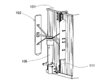
- a linear motion guide device 111 is provided on the wall of the container 101, and the linear motion guide device is provided. It was considered to attach the lower end of the support column 106 of the wind turbine 102 to the slider that can move up and down of 111.
- the wind turbine 102 is brought to the attachment position by using a hand lift 140 or the like as shown in FIG.
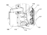
- a support column lower end member 110 is provided at the lower end of the support column 106, and the support column lower end member 110 is provided.
- a bolt (not shown) that has passed through the bolt phase through hole 118 provided in the slider 112 is screwed into the screw hole 117 provided in the slider 112 to fix the bolt.
- the wind turbine 102 when bolting to the slider 112 of the linear motion guide device 111, the wind turbine 102 may be tilted due to unevenness of the ground, etc., and the positions of the bolt phase passage hole 118 and the screw hole 117 may not match, and it may take time to install. Further, when the wind turbine 102 is bolted to the linear motion guide device 111, the wind turbine 102 is raised by the hand lift 140 or the like, and then the wind turbine 102 is bolted to the container 101 in order to increase the fixing strength, the wind turbine 102 and the container 101 It may take time to install because the holes are not aligned.
- An object of the present invention is that it is easy to transport and install. It is to provide a container-storing mobile wind power generation device that can eliminate the problem and is even easier to install.
- the container-storing mobile wind power generator of the present invention comprises a container, a wind turbine that can be stored in the container, and a generator that is driven by the wind turbine to generate electricity.
- a linear motion guide device having a slider that can move up and down is installed on the wall of the container.
- the wind turbine has a rotary wing provided at the upper end of the column and has a column lower end member that can be fixed to the slider at the lower end of the column, and can move up and down together with the slider with the column lower end member fixed to the slider.
- a guide member is provided on the slider, and the wind turbine can be fixed to the slider by screwing a bolt that is communicated with a bolt communication hole of the lower end member of the column into a screw hole provided on the guide member.
- a mounting guide portion for guiding the lower end member of the column is provided at a position and posture in which the bolt mutual hole of the lower end member of the column matches the screw hole of the guide member in a state where the lower end member of the column is not fixed to the slider. Be done.
- the wind turbine of the wind power generator stored in the container can be deployed more easily, and it is possible to immediately meet the power demand even in the disaster area such as a disaster.
- a linear motion guide device having a slider that can move up and down was installed on the wall of the container, and the wind turbine had a column lower end member that could be fixed to the slider at the lower end of the column, and the column lower end member was fixed to the slider.
- the wind turbine can be moved up and down together with the slider, and the wind turbine can be fixed to the slider by screwing a bolt that is communicated with the bolt communication hole of the lower end member of the column into the screw hole provided in the guide member. Installation work is easy.
- the mounting guide portion that guides the lower end member of the column to a position and posture in which the bolt mutual hole of the lower end member of the column matches the screw hole of the guide member while the lower end member of the column is not fixed to the slider.
- the mounting guide portion is provided on the shaft portion and a stepped bolt having a head having a diameter larger than the shaft portion, and the lower portion is provided on the lower end member of the support column, and the head portion of the stepped bolt passes through the lower portion.
- a daruma hole whose upper portion is a narrow portion having a width that allows the shaft portion of the stepped bolt to pass through and the head portion cannot pass through, and a receiving portion that receives the lower surface of the lower end member of the column.
- the structure may be composed of a stepped portion with a brim having a brim portion that rises from the anti-container side end of the receiving portion and engages with the anti-container side surface of the support lower end member.
- the mounting guide portion may have a configuration in which the lower end member of the support column can be guided to a position and posture in which the bolt exchange hole of the lower end member of the support column matches the screw hole of the guide member while the lower end member of the support column is not fixed to the slider.
- Various configurations can be adopted, but as described above, if the configuration is composed of a stepped bolt, a daruma hole, and a stepped portion with a brim, the configuration is simple and the workability is excellent. In other words, regardless of the unevenness of the ground, there is a method of determining the position with a guide pin etc. in order to make the pillar part of the wind turbine vertical to the container, but the wind turbine that is heavy and not vertical is used as the guide pin.
- the mounting guide portion is composed of the stepped bolt, the daruma hole, and the stepped portion with a brim, the stepped bolt and the stepped step portion that receives the wind turbine can be inserted into the stepped bolt. If you do so, it will be caught by its own weight and can be placed temporarily in a stable manner, enabling safe work.
- the "stepped bolt" referred to in this specification has a shaft portion without a screw following the head, and even if it has a configuration in which a male screw continues, the shaft portion and the shaft portion which is simply a male screw portion as a whole and more than this. It may also be composed of a head having a large diameter.
- the wind turbine may be a central rotating member rotatably installed around the vertical axis and a vertical wind turbine having a plurality of wings extending up and down around the central rotating member. If the wind turbine is a vertical type wind turbine, it rotates without being affected by the wind direction, and also rotates even in a breeze, and is excellent in quietness.
- upper and lower engaged portions are provided at the upper part of the container and the lower part of the support column of the wind turbine, and the upper and lower hook portions that engage with the upper and lower engaged portions are provided, and the distance between the hook portions is provided. It may be equipped with a hoist to change. If a wind turbine is installed in combination with a linear motion guidance device, the work of lifting the wind turbine to the top of the container and installing the container, or when lowering the wind turbine from the top of the container for storage, is the work of raising and lowering the wind turbine. Can be easily done.
- the winding machine can be used as a container or the like. There is no need to fix it, and it is easy to install the winder.
- the hoist may be an electric hoist.
- the hoisting machine can be applied to either the manual type or the electric type, but in the case of the configuration in which the upper and lower hooks are engaged, the manual hoisting machine is difficult to perform the hoisting operation, and the electric hoisting machine should be used. Is preferable.
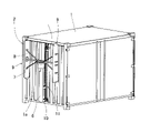
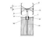
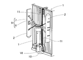
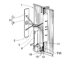
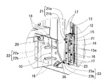
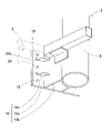
- FIG. 5 It is a perspective view which shows the use state of the container storage mobile type wind power generation apparatus which concerns on one Embodiment of this invention. It is a perspective view which shows the wind turbine unloading state of the container storage mobile type wind power generation apparatus. It is a front view which shows the use state of the container storage mobile type wind power generation apparatus. It is an enlarged front view which shows the winder of the container storage mobile type wind power generator and its surroundings. It is an enlarged perspective view which shows the wind turbine unloading state in the container front part of the container storage mobile type wind power generation apparatus. It is an enlarged perspective view which shows the VI part of FIG. It is an exploded perspective view of the same part as FIG. 5 in the container storage mobile type wind power generation apparatus.
- FIG. 6 It is an exploded perspective view of the same place as FIG. 6 in the container storage mobile type wind power generation apparatus. It is a bird view perspective view which shows the lower end member of a support column and its periphery in the container storage mobile type wind power generation apparatus. It is a front view which shows the wind turbine unloading state in the container front part of the container storage mobile wind power generation apparatus which concerns on a proposal example. It is a side view of the hand lift of the container storage mobile type wind power generation device which concerns on the proposed example. It is a perspective view which shows the fixed structure of the lower part of the wind turbine column of the container storage mobile type wind power generation device which concerns on the proposed example.
- the container-storing mobile wind power generator includes a container 1, a wind turbine 2 that can be stored in the container 1, and a generator 3 that is driven by the wind turbine 2 to generate electricity.
- the container 1 for example, a container 1 having a width narrower than the standard size is used so that it can be carried by a general 4-ton truck.
- the container 1 may be a container having standard dimensions for freight transportation.
- a plurality of blades 7 extending in the vertical direction around the central rotating member 5 are centrally rotated via an arm 8 on a central rotating member 5 rotatably installed on the upper part of the column 6 around the vertical axis. It is a vertical axis type wind turbine connected to the member 5.
- the rotary blade 9 is composed of the plurality of blades 7 and the arm 8.
- the central rotating member 5 may be a spindle or the like.
- the support column 6 is made of a round steel pipe or the like, and a central rotating member 5 of the wind turbine 2 is rotatably installed at the upper end thereof via a bearing (not shown).
- the generator 3 and the bearing are installed inside the central rotating member 5, and the rotation of the central rotating member 5 is rotatably coupled to the rotor of the generator 3.
- a linear motion guide device 11 is installed along the vertical direction on the wall 1a at one end of the container 1, a wind turbine 2 is provided on the slider 12 (see FIG. 8) of the linear motion guide device 11, and the lower end of the column is provided at the lower end of the column 6. It is attached by the member 10.
- the linear motion guide device 11 includes a rail 13 and the slider 12 that can slide up and down along the rail 13, as shown in an enlarged manner in FIG.
- the linear motion guide device 11 is composed of linear motion rolling bearings, and has a circulation path (none of which is shown) inside the slider 12 for circulating a plurality of rolling elements that are in rolling contact with the rail 13. It is provided.
- a plurality of circulation paths are provided so that the rolling element rolls in the track grooves on both side surfaces of the rail 13.
- the wind turbine 2 can be moved up and down along the linear motion guide device 11 by the winding machine 31 shown in FIG.
- an electric hoisting machine is used in this embodiment.
- a cord material such as a wire lobe (none of which is shown) is extended vertically and wound around a rotating drum provided in the hoisting machine case 32, and a hook 33, 34 is provided.
- a motor not shown
- winding and rewinding that is, the distance between the upper and lower hooks 33 and 34 can be shortened or extended. It is possible.
- the upper and lower cords may be separate from each other or may be connected to one.
- one of the upper and lower hooks 33 and 34 may be attached to the winder case 32.
- the upper and lower hooks 33 and 34 of the hoisting machine 31 are hooked on the upper and lower engaged portions 35 and 36 provided on the upper portion of the container 1 and the lower end member 10 of the support column of the wind turbine 2, respectively.
- the upper and lower engaged portions 35 and 36 are composed of, for example, eyebolts.
- the wind turbine 2 is attached to the slider 12 of the linear motion guide device 11 as follows.
- a guide member 15 is provided on the front surface of the slider 12.
- the guide member 15 is composed of two thin plate-shaped parallel guide plates 15a extending in the linear motion direction of the linear motion guide device 11.
- the guide member 15 is attached to the slider 12 with fasteners 16 such as bolts.
- Screw holes 17 are provided at a plurality of places of the guide member 15.
- the screw hole 17 may be screwed directly to the guide member 15, or may have a structure in which a nut or the like is welded.
- bolt compassion holes 18 are provided in the lower end member 10 of the column, and each bolt 19 (FIGS. 6 and 9) that has communicated with these bolt compassion holes 18 is screwed into the screw holes 17 in a tightened state.
- the support lower end member 10 of the wind turbine 2 is fixed to the slider 12.
- the support lower end member 10 is adjacent to the substrate portion 10a, the support column joining plate portion 10b protruding from the substrate portion 10a toward the support column 6, and the substrate portion 10a and the support column joining plate portion 10b. It is composed of a reinforcing plate portion 10c to which pieces are joined.
- the column joining plate portion 10b of FIG. 9 is omitted.
- FIGS. 6 and 8 and FIG. 9 are shown with different dimensional relationships.
- the lower portion of the lower end member 10 of the column is provided with a protruding portion 10d to which the lower engaged portion 36 is attached, but the protrusion 10d is not shown in FIG.
- a mounting guide portion 20 is provided as a means for facilitating the screwing work of the bolt 19.
- the mounting guide portion 20 has a support lower end member at a position and posture in which the bolt mutual hole 18 of the support lower end member 10 is aligned with the screw hole 17 of the guide member 20 in a state where the support lower end member 10 is not fixed to the slider 12. It is a means to guide the 10.
- the mounting guide portion 20 is composed of a plurality of stepped bolts 21, a daruma hole 22, and a stepped portion 23 with a brim.
- the stepped bolt 21 has a shaft portion 21a and a head portion 21b having a diameter larger than that of the shaft portion 21a.
- the daruma hole 22 is provided in the lower end member 10 of the column, and the lower portion is a large diameter portion 22b through which the head portion 21b of the stepped bolt 21 can pass, and the upper portion is a large diameter portion 22b through which the shaft portion 21a of the stepped bolt 21 can pass.
- the head 21b is a narrow portion having a width that cannot be passed through.
- the Daruma hole 22 is, so to speak, in the shape of a key hole.
- the stepped portion 23 with a brim has a receiving portion 23a that receives the lower surface of the lower end member 10 of the column, and a brim portion 23b that rises from the anti-container side end of the receiving portion 23a and engages with the anti-container side surface of the lower end member 10 of the column.
- the wind turbine 2 stored in the container 1 can be deployed more easily, and the power demand can be immediately met even in a disaster-stricken area such as a disaster.
- a linear motion guide device 11 having a slider 12 that can move up and down is installed on the wall of the container 1, and the wind turbine 2 can move up and down together with the slider 12 in a state where the support lower end member 10 at the lower end of the support column 6 is fixed to the slider 12.
- the wind turbine 2 is screwed into the screw hole 17 (FIG. 8) provided in the guide member 15 by screwing the bolt 19 (FIG. 6) through the bolt mutual hole 18 (FIG. 8) of the column lower end member 10. Since it can be fixed to the slider 12, installation work is easy.
- the linear motion guide device 11 is provided with a mounting guide portion 20.
- the mounting guide portion 20 is provided with a stepped bolt 21 and a stepped portion 23 with a brim for receiving the wind turbine 2.
- a daruma hole 22 in the shape of a key hole for hooking on the stepped bolt 21 is provided on the wind turbine 2 side.
- the mounting guide portion 20 makes the wind turbine 2 vertical, so that the screw holes are formed. Is aligned and bolting is very easy.
Landscapes
- Engineering & Computer Science (AREA)
- Life Sciences & Earth Sciences (AREA)
- Sustainable Development (AREA)
- Sustainable Energy (AREA)
- Chemical & Material Sciences (AREA)
- Combustion & Propulsion (AREA)
- Mechanical Engineering (AREA)
- General Engineering & Computer Science (AREA)
- Power Engineering (AREA)
- Wind Motors (AREA)
Abstract
Description
前記コンテナの壁に上下動可能なスライダを有する直動案内装置が設置される。
前記風車は、支柱の上端に回転翼が設けられ前記支柱の下端に前記スライダに固定可能な支柱下端部材を有し、この支柱下端部材を前記スライダに固定した状態で前記スライダと共に上下動可能である。
前記スライダにガイド部材が設けられ、前記支柱下端部材のボルト相通孔に相通されたボルトを前記ガイド部材に設けられたねじ孔にねじ込むことで前記風車を前記スライダに固定可能である。
前記支柱下端部材が前記スライダに未固定の状態で、前記支柱下端部材の前記ボルト相通孔が前記ガイド部材の前記ねじ孔と整合する位置および姿勢に前記支柱下端部材を案内する取付ガイド部が設けられる。
2…風車
3…発電機
6…支柱
9…回転翼
10…支柱下端部材
11…直動案内装置
12…スライダ
13…レール
15…ガイド部材
15a、15a…ガイドプレート
17…ねじ孔
18…ボルト相通孔
19…ボルト
20…取付ガイド部
21…段付きボルト
21a…軸部
21b…頭部
22…だるま穴
23…つば付き段差部
23a…受け部
23b…つば部
31…巻き上げ機
33,34…フック
35,36…被係合部
Claims (5)
- コンテナと、このコンテナに収納可能な風車と、この風車で駆動されて発電する発電機とを備えたコンテナ収納移動型風力発電装置であって、
前記コンテナの壁に上下動可能なスライダを有する直動案内装置が設置され、
前記風車は、支柱の上端に回転翼が設けられ前記支柱の下端に前記スライダに固定可能な支柱下端部材を有し、この支柱下端部材を前記スライダに固定した状態で前記スライダと共に上下動可能であり、
前記スライダにガイド部材が設けられ、前記支柱下端部材のボルト相通孔に相通されたボルトを前記ガイド部材に設けられたねじ孔にねじ込むことで前記風車を前記スライダに固定可能であり、
前記支柱下端部材が前記スライダに未固定の状態で、前記支柱下端部材の前記ボルト相通孔が前記ガイド部材の前記ねじ孔と整合する位置および姿勢に前記支柱下端部材を案内する取付ガイド部が設けられた、
コンテナ収納移動型風力発電装置。 - 請求項1に記載のコンテナ収納移動型風力発電装置において、前記取付ガイド部が、軸部およびこの軸部よりも大径の頭部を有する段付きボルトと、前記支柱下端部材に設けられて下部が前記段付きボルトの前記頭部が通過可能な大径部とされ上部が前記段付きボルトの前記軸部が通過可能で前記頭部が通過不能な幅の幅狭部となっただるま穴と、前記支柱下端部材の下面を受ける受け部およびこの受け部の反コンテナ側端から立ち上がって前記支柱下端部材の反コンテナ側面に係合するつば部を有するつば付き段差部とでなるコンテナ収納移動型風力発電装置。
- 請求項1または請求項2に記載のコンテナ収納移動型風力発電装置において、前記風車が上下方向軸心回りで回転自在に設置された中央回転部材およびこの中央回転部材の周囲で上下に延びる複数の翼を有する垂直型の風車であるコンテナ収納移動型風力発電装置。
- 請求項1ないし請求項3のいずれか1項に記載のコンテナ収納移動型風力発電装置において、前記コンテナの上部および前記風車の前記支柱の下部に上下の被係合部が設けられ、これら上下の被係合部に係合する上下のフック部を有しこれらフック部の間隔を変更する巻き上げ機を備えるコンテナ収納移動型風力発電装置。
- 請求項4に記載のコンテナ収納移動型風力発電装置において、前記巻き上げ機が電動巻き上げ機であるコンテナ収納移動型風力発電装置。
Priority Applications (3)
| Application Number | Priority Date | Filing Date | Title |
|---|---|---|---|
| EP21872443.3A EP4219936B1 (en) | 2020-09-28 | 2021-09-21 | Containerized mobile wind power generation apparatus |
| CN202180062833.9A CN116249830A (zh) | 2020-09-28 | 2021-09-21 | 集装箱收纳的移动型风力发电装置 |
| US18/121,341 US12180927B2 (en) | 2020-09-28 | 2023-03-14 | Containerized mobile wind power generation apparatus |
Applications Claiming Priority (2)
| Application Number | Priority Date | Filing Date | Title |
|---|---|---|---|
| JP2020162167A JP7432476B2 (ja) | 2020-09-28 | 2020-09-28 | コンテナ収納移動型風力発電装置 |
| JP2020-162167 | 2020-09-28 |
Related Child Applications (1)
| Application Number | Title | Priority Date | Filing Date |
|---|---|---|---|
| US18/121,341 Continuation US12180927B2 (en) | 2020-09-28 | 2023-03-14 | Containerized mobile wind power generation apparatus |
Publications (1)
| Publication Number | Publication Date |
|---|---|
| WO2022065314A1 true WO2022065314A1 (ja) | 2022-03-31 |
Family
ID=80845516
Family Applications (1)
| Application Number | Title | Priority Date | Filing Date |
|---|---|---|---|
| PCT/JP2021/034621 Ceased WO2022065314A1 (ja) | 2020-09-28 | 2021-09-21 | コンテナ収納移動型風力発電装置 |
Country Status (5)
| Country | Link |
|---|---|
| US (1) | US12180927B2 (ja) |
| EP (1) | EP4219936B1 (ja) |
| JP (1) | JP7432476B2 (ja) |
| CN (1) | CN116249830A (ja) |
| WO (1) | WO2022065314A1 (ja) |
Families Citing this family (4)
| Publication number | Priority date | Publication date | Assignee | Title |
|---|---|---|---|---|
| WO2023189844A1 (ja) | 2022-03-30 | 2023-10-05 | 日亜化学工業株式会社 | 発光モジュール、撮像装置、および発光モジュールの照射方法 |
| JP2024121592A (ja) * | 2023-02-27 | 2024-09-06 | Ntn株式会社 | 電源装置 |
| US12385471B2 (en) * | 2023-06-12 | 2025-08-12 | BDE Inventions, LLC | Portable and retractable off-grid turbine system |
| CN116928030A (zh) * | 2023-06-28 | 2023-10-24 | 四川华能康定水电有限责任公司 | 一种水电站采集器的供电装置 |
Citations (3)
| Publication number | Priority date | Publication date | Assignee | Title |
|---|---|---|---|---|
| JP2000097145A (ja) * | 1998-09-22 | 2000-04-04 | Suiden Co Ltd | 風力発電装置 |
| US20190326846A1 (en) * | 2016-10-14 | 2019-10-24 | HCI Eneergy, LLC | Hybrid utility system and method |
| JP2020060113A (ja) | 2018-10-09 | 2020-04-16 | Ntn株式会社 | 垂直軸風力発電装置 |
Family Cites Families (12)
| Publication number | Priority date | Publication date | Assignee | Title |
|---|---|---|---|---|
| DE3405466A1 (de) * | 1984-02-16 | 1985-08-22 | Josef 7918 Illertissen Holzner | Mobile solarstation mit windkraft-generator kombinierbar |
| CH695707A5 (de) * | 2003-04-07 | 2006-07-31 | Robert Niederer | Versorgungseinheit für Strom und Wasser auf der Basis erneuerbarer Energien. |
| CN201228615Y (zh) * | 2008-07-24 | 2009-04-29 | 崨豹科技有限公司 | 移动式风力发电装置 |
| US20100032955A1 (en) * | 2008-08-06 | 2010-02-11 | Chen Shih H | Mobile wind power generating device |
| US20110027100A1 (en) * | 2009-07-30 | 2011-02-03 | Daniel Francis Cummane | Mobile wind power station |
| US10711476B2 (en) | 2012-02-17 | 2020-07-14 | Future Proof, LLC | Modular utilities unit structure |
| US9780720B2 (en) | 2012-02-17 | 2017-10-03 | Hci Energy, Llc | Transportable hybrid power system |
| US9221136B2 (en) | 2012-02-17 | 2015-12-29 | Reza Ansari | Transportable hybrid power system |
| CN203571563U (zh) * | 2013-11-29 | 2014-04-30 | 四川新力光源股份有限公司 | 一种具有定向安装结构的吸顶灯 |
| JP6987061B2 (ja) | 2015-10-14 | 2021-12-22 | レザ・アンサリ | 可搬型複合発電システム |
| WO2020075617A1 (ja) * | 2018-10-09 | 2020-04-16 | Ntn株式会社 | 垂直軸風力発電装置およびコンテナ収容水力発電装置 |
| KR20210071021A (ko) | 2018-10-09 | 2021-06-15 | 엔티엔 가부시키가이샤 | 수직축 풍력 발전 장치 및 컨테이너 수용 수력 발전 장치 |
-
2020
- 2020-09-28 JP JP2020162167A patent/JP7432476B2/ja active Active
-
2021
- 2021-09-21 EP EP21872443.3A patent/EP4219936B1/en active Active
- 2021-09-21 WO PCT/JP2021/034621 patent/WO2022065314A1/ja not_active Ceased
- 2021-09-21 CN CN202180062833.9A patent/CN116249830A/zh active Pending
-
2023
- 2023-03-14 US US18/121,341 patent/US12180927B2/en active Active
Patent Citations (3)
| Publication number | Priority date | Publication date | Assignee | Title |
|---|---|---|---|---|
| JP2000097145A (ja) * | 1998-09-22 | 2000-04-04 | Suiden Co Ltd | 風力発電装置 |
| US20190326846A1 (en) * | 2016-10-14 | 2019-10-24 | HCI Eneergy, LLC | Hybrid utility system and method |
| JP2020060113A (ja) | 2018-10-09 | 2020-04-16 | Ntn株式会社 | 垂直軸風力発電装置 |
Non-Patent Citations (1)
| Title |
|---|
| See also references of EP4219936A4 |
Also Published As
| Publication number | Publication date |
|---|---|
| EP4219936B1 (en) | 2026-01-28 |
| US12180927B2 (en) | 2024-12-31 |
| US20230213019A1 (en) | 2023-07-06 |
| EP4219936A4 (en) | 2024-10-02 |
| JP2022054905A (ja) | 2022-04-07 |
| CN116249830A (zh) | 2023-06-09 |
| EP4219936A1 (en) | 2023-08-02 |
| JP7432476B2 (ja) | 2024-02-16 |
Similar Documents
| Publication | Publication Date | Title |
|---|---|---|
| WO2022065314A1 (ja) | コンテナ収納移動型風力発電装置 | |
| US7735808B2 (en) | Method and system for performing operations on a wind turbine | |
| US7850146B2 (en) | Lineset winch with braking parts | |
| EP2526042B1 (en) | A method for controlling the orientation of a load suspended from a bearing wire about said bearing wire and a winch arrangement | |
| EP2520792B2 (en) | Hoist system and method of providing a hoist system | |
| US20150086367A1 (en) | Portable crane for use in wind turbines | |
| US10982659B2 (en) | Method for opening a cover portion of a wind turbine | |
| BR102014019317A2 (pt) | um aparelho, sistema e método para a substituição de componentes do aerogerador | |
| CN107923361B (zh) | 移动风轮机部件的方法及用于移动风轮机部件的运输系统 | |
| US8171614B2 (en) | Systems and method of assembling a tower section | |
| EP3183201B1 (en) | Winch assembly and method of use | |
| JP5537738B2 (ja) | マグヌスロータ | |
| JP2014190313A (ja) | 吊り上げ装置、風力発電装置および風力発電装置のメンテナンス方法 | |
| KR20210031307A (ko) | 송전 철탑 작업용 이동식 윈치 장치 | |
| KR20220062580A (ko) | 크레인을 포함하는 결합체와, 크레인에 장착하기 위해 배치된 하중 안내 장치 및 상기 결합체에 사용하기 위한 하중 안내 장치 | |
| CN222293345U (zh) | 换电吊具和换电设备 | |
| CN216737284U (zh) | 一种吊装设备 | |
| CN210736022U (zh) | 一种钢结构工程施工用的防坠装置 | |
| US20260015993A1 (en) | Wind turbine assemblies and deployment methods | |
| CN222512771U (zh) | 一种搬运装置 | |
| CN220866927U (zh) | 门式起重机的门架和门式起重机 | |
| CN222024003U (zh) | 外臂锁紧装置及装卸臂 | |
| CN115195573B (zh) | 无人机综合保障运输车 | |
| CN223303278U (zh) | 一种混凝土电杆运输防护设备 | |
| WO2024045455A1 (zh) | 风力发电机组 |
Legal Events
| Date | Code | Title | Description |
|---|---|---|---|
| 121 | Ep: the epo has been informed by wipo that ep was designated in this application |
Ref document number: 21872443 Country of ref document: EP Kind code of ref document: A1 |
|
| WWE | Wipo information: entry into national phase |
Ref document number: 2021872443 Country of ref document: EP |
|
| NENP | Non-entry into the national phase |
Ref country code: DE |
|
| ENP | Entry into the national phase |
Ref document number: 2021872443 Country of ref document: EP Effective date: 20230428 |
|
| WWG | Wipo information: grant in national office |
Ref document number: 2021872443 Country of ref document: EP |