WO2022065411A1 - 車両用駆動装置 - Google Patents
車両用駆動装置 Download PDFInfo
- Publication number
- WO2022065411A1 WO2022065411A1 PCT/JP2021/034991 JP2021034991W WO2022065411A1 WO 2022065411 A1 WO2022065411 A1 WO 2022065411A1 JP 2021034991 W JP2021034991 W JP 2021034991W WO 2022065411 A1 WO2022065411 A1 WO 2022065411A1
- Authority
- WO
- WIPO (PCT)
- Prior art keywords
- pump
- gear mechanism
- gear
- electric machine
- rotary electric
- Prior art date
- Legal status (The legal status is an assumption and is not a legal conclusion. Google has not performed a legal analysis and makes no representation as to the accuracy of the status listed.)
- Ceased
Links
Images


Classifications
-
- F—MECHANICAL ENGINEERING; LIGHTING; HEATING; WEAPONS; BLASTING
- F16—ENGINEERING ELEMENTS AND UNITS; GENERAL MEASURES FOR PRODUCING AND MAINTAINING EFFECTIVE FUNCTIONING OF MACHINES OR INSTALLATIONS; THERMAL INSULATION IN GENERAL
- F16H—GEARING
- F16H37/00—Combinations of mechanical gearings, not provided for in groups F16H1/00 - F16H35/00
- F16H37/02—Combinations of mechanical gearings, not provided for in groups F16H1/00 - F16H35/00 comprising essentially only toothed or friction gearings
- F16H37/06—Combinations of mechanical gearings, not provided for in groups F16H1/00 - F16H35/00 comprising essentially only toothed or friction gearings with a plurality of driving or driven shafts; with arrangements for dividing torque between two or more intermediate shafts
- F16H37/08—Combinations of mechanical gearings, not provided for in groups F16H1/00 - F16H35/00 comprising essentially only toothed or friction gearings with a plurality of driving or driven shafts; with arrangements for dividing torque between two or more intermediate shafts with differential gearing
- F16H37/0806—Combinations of mechanical gearings, not provided for in groups F16H1/00 - F16H35/00 comprising essentially only toothed or friction gearings with a plurality of driving or driven shafts; with arrangements for dividing torque between two or more intermediate shafts with differential gearing with a plurality of driving or driven shafts
- F16H37/0813—Combinations of mechanical gearings, not provided for in groups F16H1/00 - F16H35/00 comprising essentially only toothed or friction gearings with a plurality of driving or driven shafts; with arrangements for dividing torque between two or more intermediate shafts with differential gearing with a plurality of driving or driven shafts with only one input shaft
-
- H—ELECTRICITY
- H02—GENERATION; CONVERSION OR DISTRIBUTION OF ELECTRIC POWER
- H02K—DYNAMO-ELECTRIC MACHINES
- H02K9/00—Arrangements for cooling or ventilating
- H02K9/19—Arrangements for cooling or ventilating for machines with closed casing and closed-circuit cooling using a liquid cooling medium, e.g. oil
-
- B—PERFORMING OPERATIONS; TRANSPORTING
- B60—VEHICLES IN GENERAL
- B60K—ARRANGEMENT OR MOUNTING OF PROPULSION UNITS OR OF TRANSMISSIONS IN VEHICLES; ARRANGEMENT OR MOUNTING OF PLURAL DIVERSE PRIME-MOVERS IN VEHICLES; AUXILIARY DRIVES FOR VEHICLES; INSTRUMENTATION OR DASHBOARDS FOR VEHICLES; ARRANGEMENTS IN CONNECTION WITH COOLING, AIR INTAKE, GAS EXHAUST OR FUEL SUPPLY OF PROPULSION UNITS IN VEHICLES
- B60K1/00—Arrangement or mounting of electrical propulsion units
-
- B—PERFORMING OPERATIONS; TRANSPORTING
- B60—VEHICLES IN GENERAL
- B60K—ARRANGEMENT OR MOUNTING OF PROPULSION UNITS OR OF TRANSMISSIONS IN VEHICLES; ARRANGEMENT OR MOUNTING OF PLURAL DIVERSE PRIME-MOVERS IN VEHICLES; AUXILIARY DRIVES FOR VEHICLES; INSTRUMENTATION OR DASHBOARDS FOR VEHICLES; ARRANGEMENTS IN CONNECTION WITH COOLING, AIR INTAKE, GAS EXHAUST OR FUEL SUPPLY OF PROPULSION UNITS IN VEHICLES
- B60K17/00—Arrangement or mounting of transmissions in vehicles
- B60K17/04—Arrangement or mounting of transmissions in vehicles characterised by arrangement, location or kind of gearing
- B60K17/16—Arrangement or mounting of transmissions in vehicles characterised by arrangement, location or kind of gearing of differential gearing
- B60K17/165—Arrangement or mounting of transmissions in vehicles characterised by arrangement, location or kind of gearing of differential gearing provided between independent half axles
-
- B—PERFORMING OPERATIONS; TRANSPORTING
- B60—VEHICLES IN GENERAL
- B60K—ARRANGEMENT OR MOUNTING OF PROPULSION UNITS OR OF TRANSMISSIONS IN VEHICLES; ARRANGEMENT OR MOUNTING OF PLURAL DIVERSE PRIME-MOVERS IN VEHICLES; AUXILIARY DRIVES FOR VEHICLES; INSTRUMENTATION OR DASHBOARDS FOR VEHICLES; ARRANGEMENTS IN CONNECTION WITH COOLING, AIR INTAKE, GAS EXHAUST OR FUEL SUPPLY OF PROPULSION UNITS IN VEHICLES
- B60K25/00—Auxiliary drives
- B60K25/06—Auxiliary drives from the transmission power take-off
-
- F—MECHANICAL ENGINEERING; LIGHTING; HEATING; WEAPONS; BLASTING
- F16—ENGINEERING ELEMENTS AND UNITS; GENERAL MEASURES FOR PRODUCING AND MAINTAINING EFFECTIVE FUNCTIONING OF MACHINES OR INSTALLATIONS; THERMAL INSULATION IN GENERAL
- F16H—GEARING
- F16H57/00—General details of gearing
- F16H57/02—Gearboxes; Mounting gearing therein
- F16H57/021—Shaft support structures, e.g. partition walls, bearing eyes, casing walls or covers with bearings
-
- F—MECHANICAL ENGINEERING; LIGHTING; HEATING; WEAPONS; BLASTING
- F16—ENGINEERING ELEMENTS AND UNITS; GENERAL MEASURES FOR PRODUCING AND MAINTAINING EFFECTIVE FUNCTIONING OF MACHINES OR INSTALLATIONS; THERMAL INSULATION IN GENERAL
- F16H—GEARING
- F16H57/00—General details of gearing
- F16H57/02—Gearboxes; Mounting gearing therein
- F16H57/037—Gearboxes for accommodating differential gearings
-
- F—MECHANICAL ENGINEERING; LIGHTING; HEATING; WEAPONS; BLASTING
- F16—ENGINEERING ELEMENTS AND UNITS; GENERAL MEASURES FOR PRODUCING AND MAINTAINING EFFECTIVE FUNCTIONING OF MACHINES OR INSTALLATIONS; THERMAL INSULATION IN GENERAL
- F16H—GEARING
- F16H57/00—General details of gearing
- F16H57/04—Features relating to lubrication or cooling or heating
- F16H57/042—Guidance of lubricant
- F16H57/0421—Guidance of lubricant on or within the casing, e.g. shields or baffles for collecting lubricant, tubes, pipes, grooves, channels or the like
- F16H57/0424—Lubricant guiding means in the wall of or integrated with the casing, e.g. grooves, channels, holes
-
- F—MECHANICAL ENGINEERING; LIGHTING; HEATING; WEAPONS; BLASTING
- F16—ENGINEERING ELEMENTS AND UNITS; GENERAL MEASURES FOR PRODUCING AND MAINTAINING EFFECTIVE FUNCTIONING OF MACHINES OR INSTALLATIONS; THERMAL INSULATION IN GENERAL
- F16H—GEARING
- F16H57/00—General details of gearing
- F16H57/04—Features relating to lubrication or cooling or heating
- F16H57/0434—Features relating to lubrication or cooling or heating relating to lubrication supply, e.g. pumps; Pressure control
- F16H57/0436—Pumps
-
- F—MECHANICAL ENGINEERING; LIGHTING; HEATING; WEAPONS; BLASTING
- F16—ENGINEERING ELEMENTS AND UNITS; GENERAL MEASURES FOR PRODUCING AND MAINTAINING EFFECTIVE FUNCTIONING OF MACHINES OR INSTALLATIONS; THERMAL INSULATION IN GENERAL
- F16H—GEARING
- F16H57/00—General details of gearing
- F16H57/04—Features relating to lubrication or cooling or heating
- F16H57/0434—Features relating to lubrication or cooling or heating relating to lubrication supply, e.g. pumps; Pressure control
- F16H57/0441—Arrangements of pumps
-
- F—MECHANICAL ENGINEERING; LIGHTING; HEATING; WEAPONS; BLASTING
- F16—ENGINEERING ELEMENTS AND UNITS; GENERAL MEASURES FOR PRODUCING AND MAINTAINING EFFECTIVE FUNCTIONING OF MACHINES OR INSTALLATIONS; THERMAL INSULATION IN GENERAL
- F16H—GEARING
- F16H57/00—General details of gearing
- F16H57/04—Features relating to lubrication or cooling or heating
- F16H57/0457—Splash lubrication
-
- F—MECHANICAL ENGINEERING; LIGHTING; HEATING; WEAPONS; BLASTING
- F16—ENGINEERING ELEMENTS AND UNITS; GENERAL MEASURES FOR PRODUCING AND MAINTAINING EFFECTIVE FUNCTIONING OF MACHINES OR INSTALLATIONS; THERMAL INSULATION IN GENERAL
- F16H—GEARING
- F16H57/00—General details of gearing
- F16H57/04—Features relating to lubrication or cooling or heating
- F16H57/0467—Elements of gearings to be lubricated, cooled or heated
- F16H57/0469—Bearings or seals
- F16H57/0471—Bearing
-
- F—MECHANICAL ENGINEERING; LIGHTING; HEATING; WEAPONS; BLASTING
- F16—ENGINEERING ELEMENTS AND UNITS; GENERAL MEASURES FOR PRODUCING AND MAINTAINING EFFECTIVE FUNCTIONING OF MACHINES OR INSTALLATIONS; THERMAL INSULATION IN GENERAL
- F16H—GEARING
- F16H57/00—General details of gearing
- F16H57/04—Features relating to lubrication or cooling or heating
- F16H57/0467—Elements of gearings to be lubricated, cooled or heated
- F16H57/0476—Electric machines and gearing, i.e. joint lubrication or cooling or heating thereof
-
- F—MECHANICAL ENGINEERING; LIGHTING; HEATING; WEAPONS; BLASTING
- F16—ENGINEERING ELEMENTS AND UNITS; GENERAL MEASURES FOR PRODUCING AND MAINTAINING EFFECTIVE FUNCTIONING OF MACHINES OR INSTALLATIONS; THERMAL INSULATION IN GENERAL
- F16H—GEARING
- F16H57/00—General details of gearing
- F16H57/04—Features relating to lubrication or cooling or heating
- F16H57/048—Type of gearings to be lubricated, cooled or heated
- F16H57/0482—Gearings with gears having orbital motion
- F16H57/0483—Axle or inter-axle differentials
-
- H—ELECTRICITY
- H02—GENERATION; CONVERSION OR DISTRIBUTION OF ELECTRIC POWER
- H02K—DYNAMO-ELECTRIC MACHINES
- H02K7/00—Arrangements for handling mechanical energy structurally associated with dynamo-electric machines, e.g. structural association with mechanical driving motors or auxiliary dynamo-electric machines
- H02K7/10—Structural association with clutches, brakes, gears, pulleys or mechanical starters
- H02K7/116—Structural association with clutches, brakes, gears, pulleys or mechanical starters with gears
-
- B—PERFORMING OPERATIONS; TRANSPORTING
- B60—VEHICLES IN GENERAL
- B60K—ARRANGEMENT OR MOUNTING OF PROPULSION UNITS OR OF TRANSMISSIONS IN VEHICLES; ARRANGEMENT OR MOUNTING OF PLURAL DIVERSE PRIME-MOVERS IN VEHICLES; AUXILIARY DRIVES FOR VEHICLES; INSTRUMENTATION OR DASHBOARDS FOR VEHICLES; ARRANGEMENTS IN CONNECTION WITH COOLING, AIR INTAKE, GAS EXHAUST OR FUEL SUPPLY OF PROPULSION UNITS IN VEHICLES
- B60K1/00—Arrangement or mounting of electrical propulsion units
- B60K2001/001—Arrangement or mounting of electrical propulsion units one motor mounted on a propulsion axle for rotating right and left wheels of this axle
-
- B—PERFORMING OPERATIONS; TRANSPORTING
- B60—VEHICLES IN GENERAL
- B60K—ARRANGEMENT OR MOUNTING OF PROPULSION UNITS OR OF TRANSMISSIONS IN VEHICLES; ARRANGEMENT OR MOUNTING OF PLURAL DIVERSE PRIME-MOVERS IN VEHICLES; AUXILIARY DRIVES FOR VEHICLES; INSTRUMENTATION OR DASHBOARDS FOR VEHICLES; ARRANGEMENTS IN CONNECTION WITH COOLING, AIR INTAKE, GAS EXHAUST OR FUEL SUPPLY OF PROPULSION UNITS IN VEHICLES
- B60K25/00—Auxiliary drives
- B60K2025/005—Auxiliary drives driven by electric motors forming part of the propulsion unit
-
- B—PERFORMING OPERATIONS; TRANSPORTING
- B60—VEHICLES IN GENERAL
- B60Y—INDEXING SCHEME RELATING TO ASPECTS CROSS-CUTTING VEHICLE TECHNOLOGY
- B60Y2200/00—Type of vehicle
- B60Y2200/90—Vehicles comprising electric prime movers
- B60Y2200/91—Electric vehicles
-
- B—PERFORMING OPERATIONS; TRANSPORTING
- B60—VEHICLES IN GENERAL
- B60Y—INDEXING SCHEME RELATING TO ASPECTS CROSS-CUTTING VEHICLE TECHNOLOGY
- B60Y2306/00—Other features of vehicle sub-units
- B60Y2306/03—Lubrication
-
- B—PERFORMING OPERATIONS; TRANSPORTING
- B60—VEHICLES IN GENERAL
- B60Y—INDEXING SCHEME RELATING TO ASPECTS CROSS-CUTTING VEHICLE TECHNOLOGY
- B60Y2400/00—Special features of vehicle units
- B60Y2400/70—Gearings
- B60Y2400/78—Pumps, e.g. jet type
-
- B—PERFORMING OPERATIONS; TRANSPORTING
- B60—VEHICLES IN GENERAL
- B60Y—INDEXING SCHEME RELATING TO ASPECTS CROSS-CUTTING VEHICLE TECHNOLOGY
- B60Y2400/00—Special features of vehicle units
- B60Y2400/87—Auxiliary drives
-
- B—PERFORMING OPERATIONS; TRANSPORTING
- B60—VEHICLES IN GENERAL
- B60Y—INDEXING SCHEME RELATING TO ASPECTS CROSS-CUTTING VEHICLE TECHNOLOGY
- B60Y2410/00—Constructional features of vehicle sub-units
- B60Y2410/10—Housings
-
- B—PERFORMING OPERATIONS; TRANSPORTING
- B60—VEHICLES IN GENERAL
- B60Y—INDEXING SCHEME RELATING TO ASPECTS CROSS-CUTTING VEHICLE TECHNOLOGY
- B60Y2410/00—Constructional features of vehicle sub-units
- B60Y2410/102—Shaft arrangements; Shaft supports, e.g. bearings
-
- F—MECHANICAL ENGINEERING; LIGHTING; HEATING; WEAPONS; BLASTING
- F16—ENGINEERING ELEMENTS AND UNITS; GENERAL MEASURES FOR PRODUCING AND MAINTAINING EFFECTIVE FUNCTIONING OF MACHINES OR INSTALLATIONS; THERMAL INSULATION IN GENERAL
- F16H—GEARING
- F16H57/00—General details of gearing
- F16H57/02—Gearboxes; Mounting gearing therein
- F16H2057/02034—Gearboxes combined or connected with electric machines
-
- F—MECHANICAL ENGINEERING; LIGHTING; HEATING; WEAPONS; BLASTING
- F16—ENGINEERING ELEMENTS AND UNITS; GENERAL MEASURES FOR PRODUCING AND MAINTAINING EFFECTIVE FUNCTIONING OF MACHINES OR INSTALLATIONS; THERMAL INSULATION IN GENERAL
- F16H—GEARING
- F16H57/00—General details of gearing
- F16H57/02—Gearboxes; Mounting gearing therein
- F16H2057/02039—Gearboxes for particular applications
- F16H2057/02043—Gearboxes for particular applications for vehicle transmissions
- F16H2057/02052—Axle units; Transfer casings for four wheel drive
-
- F—MECHANICAL ENGINEERING; LIGHTING; HEATING; WEAPONS; BLASTING
- F16—ENGINEERING ELEMENTS AND UNITS; GENERAL MEASURES FOR PRODUCING AND MAINTAINING EFFECTIVE FUNCTIONING OF MACHINES OR INSTALLATIONS; THERMAL INSULATION IN GENERAL
- F16H—GEARING
- F16H57/00—General details of gearing
- F16H57/04—Features relating to lubrication or cooling or heating
- F16H57/042—Guidance of lubricant
- F16H57/0421—Guidance of lubricant on or within the casing, e.g. shields or baffles for collecting lubricant, tubes, pipes, grooves, channels or the like
- F16H57/0426—Means for guiding lubricant into an axial channel of a shaft
-
- F—MECHANICAL ENGINEERING; LIGHTING; HEATING; WEAPONS; BLASTING
- F16—ENGINEERING ELEMENTS AND UNITS; GENERAL MEASURES FOR PRODUCING AND MAINTAINING EFFECTIVE FUNCTIONING OF MACHINES OR INSTALLATIONS; THERMAL INSULATION IN GENERAL
- F16H—GEARING
- F16H57/00—General details of gearing
- F16H57/04—Features relating to lubrication or cooling or heating
- F16H57/042—Guidance of lubricant
- F16H57/043—Guidance of lubricant within rotary parts, e.g. axial channels or radial openings in shafts
-
- Y—GENERAL TAGGING OF NEW TECHNOLOGICAL DEVELOPMENTS; GENERAL TAGGING OF CROSS-SECTIONAL TECHNOLOGIES SPANNING OVER SEVERAL SECTIONS OF THE IPC; TECHNICAL SUBJECTS COVERED BY FORMER USPC CROSS-REFERENCE ART COLLECTIONS [XRACs] AND DIGESTS
- Y02—TECHNOLOGIES OR APPLICATIONS FOR MITIGATION OR ADAPTATION AGAINST CLIMATE CHANGE
- Y02T—CLIMATE CHANGE MITIGATION TECHNOLOGIES RELATED TO TRANSPORTATION
- Y02T10/00—Road transport of goods or passengers
- Y02T10/60—Other road transportation technologies with climate change mitigation effect
- Y02T10/62—Hybrid vehicles
Definitions
- the present invention is transmitted from the side of a rotary electric machine, a rotary electric machine that functions as a driving force source for wheels, an input member that is driven and connected to the rotary electric machine, a pair of output members that are each driven and connected to the wheel, and a rotary electric machine.
- the present invention relates to a vehicle drive device including a differential gear mechanism that distributes rotation to a pair of output members, and at least a hydraulic pump that supplies oil to a rotary electric machine.
- Patent Document 1 An example of such a vehicle drive device is disclosed in Patent Document 1 below.
- background technology and “problems to be solved by the invention”
- the reference numerals in Patent Document 1 are quoted in parentheses.
- a counter gear mechanism (22) is provided in the power transmission path between the input member (22a) driven and connected to the rotary electric machine (12) and the differential gear mechanism (24). Has been done.
- the pump input shaft (50) of the hydraulic pump (40) is connected to the counter shaft (22e) of the counter gear mechanism (22) so as to rotate integrally. Therefore, the hydraulic pump (40) is driven as the counter gear mechanism (22) rotates.
- the hydraulic pump (40) is arranged outside the case (18) that houses the rotary electric machine (12) and the like. Specifically, the pump cover (48) is joined to the outer surface of the side wall portion (36a) of the case (18).
- a pump chamber (S3) for accommodating the pump rotors (40a and 40b) is formed between the side wall portion (36a) and the pump cover (48).
- the hydraulic pump (40) is provided with a seal member and a relief valve (56) in order to prevent oil from leaking from the pump chamber (S3) to the outside of the case (18).
- the sealing member is a member that tightly seals between the side wall portion (36a) and the pump cover (48) (see FIG. 2 of Patent Document 1).
- the relief valve (56) is a valve that discharges a part of the oil supplied to the oil passage into the case (18) when the pressure of the oil passage communicating with the pump chamber (S3) becomes abnormally high. be.
- the hydraulic pump (40) has a complicated configuration.
- the characteristic configuration of the vehicle drive device is A rotating electric machine that functions as a driving force source for wheels, The input member driven and connected to the rotary electric machine and A pair of output members, each driven and connected to the wheel, A differential gear mechanism that distributes the rotation transmitted from the rotary electric machine side to the pair of output members.
- a transmission gear mechanism that drives and connects the input member and the differential gear mechanism,
- a hydraulic pump provided with a pump rotor and a pump chamber for accommodating the pump rotor, and at least supplying oil to the rotary electric machine.
- the rotary electric machine, the input member, the differential gear mechanism, the transmission gear mechanism, and a case for accommodating the hydraulic pump are provided.
- the case With the direction along the rotation axis of the rotary electric machine as the axial direction,
- the case includes a partition wall that separates a first accommodation chamber for accommodating the rotary electric machine and a second accommodation chamber for accommodating the transmission gear mechanism and the differential gear mechanism in the axial direction.
- the pump chamber is at a point formed on the partition wall so as to be located between the first storage chamber and the second storage chamber in the axial direction.
- the pump chamber of the hydraulic pump is formed on the partition wall that divides the internal space of the case into the first accommodation chamber and the second accommodation chamber. Therefore, even if the oil leaks from the pump chamber, the oil only flows into the first storage chamber or the second storage chamber and does not leak to the outside of the case.
- the hydraulic pump can be configured in a simple manner.
- the vehicle drive device 100 includes a rotary electric machine MG, an input member 1, a transmission gear mechanism 2, a differential gear mechanism 3, a pair of output members 4, and a case 9. , Is equipped.
- the direction along the rotation axis of the rotary electric machine MG is referred to as "axial direction L".
- one side of the axial direction L is referred to as “the first side in the axial direction L1”
- the other side is referred to as “the second side L2 in the axial direction”.
- the direction orthogonal to the rotation axis of the rotating member such as the rotary electric machine MG is defined as the "diameter direction R" with respect to each rotation axis.
- the case 9 houses the rotary electric machine MG, the input member 1, the transmission gear mechanism 2, and the differential gear mechanism 3. In this embodiment, the case 9 also houses a pair of output members 4.
- the case 9 includes a partition wall 91.
- the partition wall 91 is formed so as to partition the internal space of the case 9. Specifically, the partition wall 91 divides the first accommodating chamber A1 accommodating the rotary electric machine MG and the second accommodating chamber A2 accommodating the transmission gear mechanism 2 and the differential gear mechanism 3 in the axial direction L. Is formed in.
- the first accommodation chamber A1 accommodates a part of the input member 1 in addition to the rotary electric machine MG.
- the second accommodation chamber A2 also accommodates a part of the input member 1 and a pair of output members 4.
- the case 9 further includes a first peripheral wall portion 92, a first side wall portion 93, a second peripheral wall portion 94, and a second side wall portion 95.
- the first peripheral wall portion 92 is formed in a cylindrical shape having an axial center along the axial direction L.
- the first side wall portion 93 is formed so as to close the opening of the first peripheral wall portion 92 on the first side L1 in the axial direction.
- the second peripheral wall portion 94 is formed in a cylindrical shape having an axial center along the axial direction L.
- the second side wall portion 95 is formed so as to close the opening on the second side L2 in the axial direction of the second peripheral wall portion 94.
- the partition wall 91 is formed so as to close the opening of the axial second side L2 of the first peripheral wall portion 92 and the opening of the axial first side L1 of the second peripheral wall portion 94. ing.
- the first peripheral wall portion 92 extends from the partition wall 91 to the first side L1 in the axial direction
- the second peripheral wall portion 94 extends from the partition wall 91 to the second side L2 in the axial direction. It is formed like this.
- the partition wall 91 is integrally formed with the first peripheral wall portion 92 and the second peripheral wall portion 94.
- the space surrounded by the partition wall 91, the first peripheral wall portion 92, and the first side wall portion 93 inside the case 9 is formed as the first accommodation chamber A1. Further, a space surrounded by the partition wall 91, the second peripheral wall portion 94, and the second side wall portion 95 inside the case 9 is formed as the second accommodation chamber A2.
- the rotary electric machine MG functions as a driving force source for the wheels W.
- the rotary electric machine MG has a function as a motor (motor) that receives power supply and generates power, and a function as a generator (generator) that receives power supply and generates power.
- the rotary electric machine MG is electrically connected to a power storage device (not shown) such as a battery or a capacitor. Then, the rotary electric machine MG is driven by the electric power stored in the power storage device to generate a driving force. Further, the rotary electric machine MG generates electricity by the driving force transmitted from the wheel W side to charge the power storage device.
- the rotary electric machine MG is equipped with a stator ST and a rotor RT.
- the stator ST has a stator core STC fixed to a non-rotating member (here, case 9).
- the rotor RT has a rotor core RTC rotatably supported with respect to the stator ST, and a rotor shaft RTS connected so as to rotate integrally with the rotor core RTC.
- the rotary electric machine MG is a rotary field type rotary electric machine. Therefore, the coil C is wound around the stator core STC so as to form coil end portions protruding from both sides of the stator core STC on both sides in the axial direction (L1 on the first side in the axial direction and L2 on the second side in the axial direction). ing.
- the rotor core RTC is provided with a permanent magnet PM.
- the rotary electric machine MG is an inner rotor type rotary electric machine. Therefore, the rotor core RTC is arranged inside the radial direction R with respect to the stator core STC.
- the rotor core RTC supports the rotor shaft RTS from the outside in the radial direction R.
- the rotor shaft RTS is formed so as to extend along the axial direction L.
- the rotor shaft RTS is formed in a cylindrical shape having an axial center along the axial direction L.
- the rotor shaft RTS is rotatably supported with respect to the case 9 by the first rotor bearing B11 and the second rotor bearing B12 arranged on the second side L2 in the axial direction from the first rotor bearing B11.
- the end portion of the rotor shaft RTS on the first side L1 in the axial direction is rotatably supported with respect to the first side wall portion 93 of the case 9 via the first rotor bearing B11.
- the end portion of the rotor shaft RTS on the second side L2 in the axial direction is rotatably supported with respect to the second side wall portion 95 of the case 9 via the second rotor bearing B12.
- the first rotor bearing B11 and the second rotor bearing B12 are ball bearings.
- the input member 1 is driven and connected to the rotary electric machine MG.
- the input member 1 penetrates the partition wall 91 of the case 9 in the axial direction L, and is arranged over the first accommodation chamber A1 and the second accommodation chamber A2.
- the input member 1 is arranged coaxially with the rotor shaft RTS of the rotary electric machine MG, and is connected so as to rotate integrally with the rotor shaft RTS in the first accommodation chamber A1.
- the portion of the input member 1 on the first side L1 in the axial direction with respect to the partition wall 91 is inside the radial direction R with respect to the portion of the rotor shaft RTS on the second side L2 in the axial direction with respect to the rotor core RTC. Is located in. Then, those parts are connected to each other by spline engagement so as to rotate integrally.
- driving connection refers to a state in which two rotating elements are connected so as to be able to transmit a driving force, and a state in which the two rotating elements are connected so as to rotate integrally, or the said. It includes a state in which two rotating elements are mutably connected so that a driving force can be transmitted through one or more transmission members.
- Such transmission members include various members that transmit rotation at the same speed or at different speeds, such as a shaft, a gear mechanism, a belt, and a chain.
- the transmission member may include an engaging device that selectively transmits rotation and driving force, for example, a friction engaging device, a meshing type engaging device, and the like.
- the term "drive connection" for each rotating element means a state in which they are driven and connected to each other without the intervention of other rotating elements.
- the input member 1 is rotatable with respect to the case 9 by the first input bearing B21 and the second input bearing B22 arranged on the second side L2 in the axial direction from the first input bearing B21. It is supported.
- the portion of the input member 1 penetrating the partition wall 91 of the case 9 is rotatably supported with respect to the partition wall 91 via the first input bearing B21.
- the end portion of the second side L2 in the axial direction of the input member 1 is rotatably supported with respect to the second side wall portion 95 of the case 9 via the second input bearing B22.
- the first input bearing B21 and the second input bearing B22 are ball bearings.
- the transmission gear mechanism 2 drives and connects the input member 1 and the differential gear mechanism 3. That is, the transmission gear mechanism 2 transmits the rotation from the input member 1 to the differential gear mechanism 3.
- the transmission gear mechanism 2 includes a first gear 21 and a counter gear mechanism 22.
- the first gear 21 is arranged on the first axis X1. Specifically, the first gear 21 is arranged so as to rotate with the first axis X1 as the center of rotation.
- the first axis X1 is the rotation axis center of the input member 1.
- the input member 1 is arranged coaxially with the rotor shaft RTS of the rotary electric machine MG. Therefore, the first axis X1 is arranged along the axial direction L, which is the direction along the rotation axis center of the rotary electric machine MG.
- the first gear 21 is connected so as to rotate integrally with the input member 1.
- the first gear 21 is integrally formed with the input member 1.
- the first gear 21 is arranged between the first input bearing B21 and the second input bearing B22 in the axial direction L.
- the counter gear mechanism 22 is arranged on the second axis X2, which is different from the first axis X1.
- the second axis X2 is the rotation axis center of the counter gear mechanism 22.
- the second axis X2 is arranged in parallel with the first axis X1. That is, in the present embodiment, the second axis X2 is arranged along the axial direction L.
- the counter gear mechanism 22 is a counter shaft that connects a second gear 23 that meshes with the first gear 21, a third gear 24 that rotates integrally with the second gear 23, and the second gear 23 and the third gear 24. 25 and.
- the second gear 23, the third gear 24, and the counter shaft 25 are arranged on the second shaft X2.
- Each of the second gear 23 and the third gear 24 is connected so as to rotate integrally with the counter shaft 25.
- the second gear 23 is connected to the counter shaft 25 by spline engagement.
- the third gear 24 is integrally formed with the counter shaft 25. Further, the third gear 24 is formed to have a smaller diameter than the second gear 23.
- the counter shaft 25 is formed so as to extend along the second shaft X2.
- the counter shaft 25 is rotatable with respect to the case 9 by the first counter bearing B31 and the second counter bearing B32 arranged on the second side L2 in the axial direction from the first counter bearing B31. It is supported.
- the end portion of the counter shaft 25 on the first side L1 in the axial direction is rotatably supported with respect to the partition wall 91 of the case 9 via the first counter bearing B31.
- the end of the second side L2 in the axial direction of the counter shaft 25 is rotatably supported with respect to the second side wall portion 95 of the case 9 via the second counter bearing B32.
- the first counter bearing B31 and the second counter bearing B32 are conical roller bearings.
- the differential gear mechanism 3 is configured to distribute the rotation transmitted from the rotary electric machine MG side to the pair of output members 4.
- the differential gear mechanism 3 includes a fourth gear 31 that meshes with the third gear 24 of the counter gear mechanism 22. Therefore, in the present embodiment, the differential gear mechanism 3 distributes the rotation of the fourth gear 31 to the pair of output members 4.
- the fourth gear 31 is arranged on the third axis X3, which is different from the first axis X1 and the second axis X2.
- the third axis X3 is the rotation axis center of the fourth gear 31.
- the third axis X3 is arranged in parallel with both the first axis X1 and the second axis X2. That is, in the present embodiment, the third axis X3 is arranged along the axial direction L.
- the differential gear mechanism 3 further includes a differential case 32, a pair of pinion gears 33, and a first side gear 34 and a second side gear 35.
- the pair of pinion gears 33, and the first side gear 34 and the second side gear 35 are all bevel gears.
- the differential case 32 is a hollow member that houses a pair of pinion gears 33, and a first side gear 34 and a second side gear 35.
- the differential case 32 is connected so as to rotate integrally with the fourth gear 31.
- the fourth gear 31 is connected to the differential case 32 by using bolts.
- the differential case 32 is provided with respect to the case 9 by the first differential bearing B41 and the second differential bearing B42 arranged on the second side L2 in the axial direction from the first differential bearing B41. It is rotatably supported.
- the end of the axial first side L1 of the differential case 32 is rotatably supported with respect to the partition wall 91 of the case 9 via the first differential bearing B41.
- the end portion of the second side L2 in the axial direction of the differential case 32 is rotatably supported with respect to the second side wall portion 95 of the case 9 via the second differential bearing B42.
- the first differential bearing B41 and the second differential bearing B42 are conical roller bearings.
- the pair of pinion gears 33 are arranged so as to face each other at intervals in the radial direction R with respect to the third axis X3.
- the pair of pinion gears 33 are attached to a pinion shaft 36 supported so as to rotate integrally with the differential case 32.
- Each of the pair of pinion gears 33 is configured to be rotatable (rotating) about the pinion shaft 36 and rotating (revolving) about the third axis X3.
- the first side gear 34 and the second side gear 35 mesh with a pair of pinion gears 33.
- the first side gear 34 and the second side gear 35 are arranged so as to rotate with the third axis X3 as the rotation axis center.
- the first side gear 34 and the second side gear 35 are arranged so as to face each other with the pinion shaft 36 interposed therebetween at a distance from each other in the axial direction L.
- the first side gear 34 is arranged on the first side L1 in the axial direction with respect to the second side gear 35.
- Each of the pair of output members 4 is drive-connected to the wheel W.
- the pair of output members 4 are arranged side by side on the third axis X3.
- the output member 4 on the first side L1 in the axial direction is referred to as the "first output member 41”
- the output member 4 on the second side L2 in the axial direction is referred to as the "second output member 42”. ".
- the second output member 42 is connected so as to rotate integrally with the second side gear 35.
- the second output member 42 is integrally formed with the second side gear 35.
- the second output member 42 is connected so as to rotate integrally with the drive shaft DS on the second side L2 in the axial direction.
- the second output member 42 is formed in a cylindrical shape having an axial center along the axial direction L, and is arranged inside the radial direction R with respect to the second side gear 35. Then, the drive shaft DS is inserted from the axial second side L2 inside the radial direction R with respect to the second output member 42, and they are connected to each other by spline engagement.
- the first output member 41 is connected so as to rotate integrally with the first side gear 34.
- the first output member 41 is integrally formed with the first side gear 34.
- the first output member 41 is connected via the transmission shaft 5 so as to rotate integrally with the drive shaft DS on the first side L1 in the axial direction.
- the first output member 41 is formed in a cylindrical shape having an axial center along the axial direction L, and is arranged inside the radial direction R with respect to the first side gear 34. Then, the transmission shaft 5 is inserted from the axial first side L1 inside the radial direction R with respect to the first output member 41, and they are connected to each other by spline engagement.
- the transmission shaft 5 is a shaft member whose rotation axis is the third axis X3.
- the transmission shaft 5 penetrates the partition wall 91 of the case 9 in the axial direction L, and is arranged over the first storage chamber A1 and the second storage chamber A2.
- the transmission shaft 5 is connected to the drive shaft DS on the first side L1 in the axial direction so as to rotate integrally with the drive shaft DS.
- the portion of the transmission shaft 5 from the end surface of the axial first side L1 to the axial first side L1 from the center of the axial direction L is a cylinder that opens to the axial first side L1. It is formed in a shape.
- the first drive shaft DS1 is inserted from the axial first side L1 to the inside of the radial direction R with respect to the tubular portion of the transmission shaft 5, and they are connected to each other by spline engagement.
- the transmission shaft 5 is rotatably supported with respect to the case 9 by the output bearing B5.
- the end portion of the transmission shaft 5 on the first side L1 in the axial direction is rotatably supported with respect to the first side wall portion 93 of the case 9 via the output bearing B5.
- the vehicle drive device 100 includes a hydraulic pump 6.
- the hydraulic pump 6 is housed in the case 9.
- the hydraulic pump 6 is configured to supply oil to at least the rotary electric machine MG.
- the hydraulic pump 6 supplies oil to the coil end portion of the coil C and the inner peripheral surface of the rotor shaft RTS in the rotary electric machine MG.
- the hydraulic pump 6 supplies oil to various bearings, gear meshing portions, and the like of the vehicle drive device 100. That is, in the present embodiment, the oil discharged from the hydraulic pump 6 is used only for cooling the rotary electric machine MG and for lubricating various bearings, gear meshing portions, and the like.
- the hydraulic pump 6 includes a pump rotor 61 and a pump chamber 62 for accommodating the pump rotor 61.
- the hydraulic pump 6 further includes a pump cover 63 joined to the partition wall 91 of the case 9, and a pump input shaft 64 connected so as to rotate integrally with the pump rotor 61. ..
- the hydraulic pump 6 is an internal gear pump. Therefore, the pump rotor 61 includes an inner rotor 611 and an outer rotor 612 arranged outside the radial direction R with respect to the inner rotor 611.
- the external teeth formed on the outer peripheral surface of the inner rotor 611 mesh with the internal teeth formed on the inner peripheral surface of the outer rotor 612.
- the pump chamber 62 is formed on the partition wall 91 of the case 9.
- the pump chamber 62 is arranged between the first accommodation chamber A1 and the second accommodation chamber A2 in the axial direction L.
- the pump chamber 62 is formed by using the target surface S of the partition wall 91 of the case 9.
- the target surface S is a surface of the partition wall 91 facing one side in the axial direction L.
- the target surface S is a surface of the partition wall 91 facing the side of the first accommodation chamber A1 (here, the first side L1 in the axial direction).
- the pump chamber 62 is formed by a recess formed so that the target surface S of the partition wall 91 is recessed. Specifically, the pump chamber 62 is a space surrounded by the first inner surface 9a and the second inner surface 9b of the partition wall 91.
- the first inner surface 9a is formed in a cylindrical shape that covers the outer peripheral surface of the outer rotor 612.
- the second inner surface 9b is formed in a planar shape covering the surfaces of the inner rotor 611 and the outer rotor 612 on the second side L2 in the axial direction.
- the first inner surface 9a is formed so as to extend from the first side surface 9c, which is the side surface of the axial first side L1 of the partition wall 91, to the axial second side L2.
- the second inner surface 9b is formed so as to extend inward in the radial direction R from the end portion of the second side L2 in the axial direction of the first inner surface 9a.
- the second inner surface 9b and the first side surface 9c correspond to the target surface S.
- the dimension of the first inner surface 9a in the axial direction L is slightly larger than the dimension of the outer rotor 612 in the axial direction L.
- the pump chamber 62 of the hydraulic pump 6 is formed on the partition wall 91 that divides the internal space of the case 9 into the first accommodation chamber A1 and the second accommodation chamber A2. Therefore, even if the oil leaks from the pump chamber 62, the oil only flows into the first storage chamber A1 or the second storage chamber A2 and does not leak to the outside of the case 9.
- the hydraulic pump 6 can have a simple configuration.
- the oil discharged from the hydraulic pump 6 is used only for cooling the rotary electric machine MG and for lubricating various bearings, gear meshing portions, and the like.
- the hydraulic pressure for controlling the engaging device is applied in the configuration without the seal member, the relief valve, or the like as described above. It may not be supplied properly.
- the oil discharged from the hydraulic pump 6 is not used for controlling the engaging device, even if the oil leaks from the pump chamber 62, the running of the vehicle is not affected.
- the discharge port 6a and the suction port (not shown) of the hydraulic pump 6 are formed so as to open to the second inner surface 9b.
- the discharge port 6a is a port for the pump rotor 61 to discharge oil to the outside of the pump chamber 62, and is connected to a discharge oil passage (here, a first oil passage P1 described later).
- the suction port is a port for the pump rotor 61 to suck oil from the outside of the pump chamber 62, and is connected to a suction oil passage.
- the pump cover 63 is joined to the partition wall 91 so as to face the target surface S in the axial direction L.
- a pump chamber 62 is formed between the pump cover 63 and the pump cover 63 in the axial direction L.
- the pump cover 63 is partitioned from the axial first side L1 so as to cover the pump rotor 61 housed in the pump chamber 62 formed by the first inner surface 9a and the second inner surface 9b of the partition wall 91. It is joined to the wall 91.
- the hydraulic pump 6 further includes a pump cover 63 joined to the partition wall 91.
- the pump chamber 62 is formed between the partition wall 91 in the axial direction L and the pump cover 63.
- the pump chamber 62 can be appropriately formed by using a part of the partition wall 91.
- the amount of oil leaking from the pump chamber 62 can be suppressed to a small amount. Therefore, the hydraulic pump 6 can be configured in a simpler manner while preventing the oil discharged from the hydraulic pump 6 from flowing out to the outside of the case 9.
- the pump input shaft 64 is an input element of the hydraulic pump 6.
- the pump input shaft 64 is arranged so as to penetrate the partition wall 91 in the axial direction L. That is, in the present embodiment, the pump input shaft 64 is arranged over the first accommodation chamber A1 and the second accommodation chamber A2. Then, in the present embodiment, the pump input shaft 64 is drive-connected to the shaft of the transmission gear mechanism 2 in the second accommodating chamber A2.
- the pump input shaft 64 is arranged on the second shaft X2 and is connected so as to rotate integrally with the counter shaft 25.
- the portion of the pump input shaft 64 protruding from the partition wall 91 on the axial second side L2 is formed so as to be recessed from the end surface of the axial first side L1 of the counter shaft 25 to the axial second side L2. It is inserted in the opening. And they are connected to each other by spline engagement.
- the hydraulic pump 6 further includes a pump input shaft 64 connected so as to rotate integrally with the pump rotor 61.
- the pump input shaft 64 is arranged so as to penetrate the partition wall 91 in the axial direction L, and is driven and connected to the shaft of the transmission gear mechanism 2 in the second accommodation chamber A2.
- the pump input shaft 64 can be rotatably supported with respect to the partition wall 91 of the case 9, and the pump rotor 61 is appropriately rotationally driven by utilizing the rotation of the transmission gear mechanism 2. Can be done.
- the transmission gear mechanism 2 is arranged on the first axis X1 which is the rotation axis of the input member 1 and is connected to the first gear 21 so as to rotate integrally with the input member 1.
- a counter gear mechanism 22 arranged on the second axis X2, which is different from the first axis X1.
- the counter gear mechanism 22 is a counter shaft that connects a second gear 23 that meshes with the first gear 21, a third gear 24 that rotates integrally with the second gear 23, and the second gear 23 and the third gear 24.
- the differential gear mechanism 3 is arranged on a third axis X3, which is different from the first axis X1 and the second axis X2, and includes a fourth gear 31 that meshes with the third gear 24.
- the hydraulic pump 6 further comprises a pump input shaft 64 connected to rotate integrally with the pump rotor 61.
- the pump input shaft 64 is arranged on the second shaft X2 and is connected to the counter shaft 25 so as to rotate integrally.
- the rotation speed of the counter gear mechanism 22 is generally smaller than the rotation speed of the rotary electric machine MG. Therefore, according to the configuration in which the hydraulic pump 6 is driven by the rotation of the counter shaft 25 as described above, the rotational speed of the pump rotor 61 is reduced as compared with the configuration in which the hydraulic pump 6 is driven by the rotary electric machine MG. Can be done. Therefore, the energy loss due to the high-speed rotation of the hydraulic pump 6 can be suppressed to a small value, and the energy efficiency of the vehicle drive device 100 can be improved.
- the first oil passage P1, the second oil passage P2, the third oil passage P3, and the fourth oil passage P4 are formed on the partition wall 91 of the case 9.
- the first oil passage P1 is formed inside the partition wall 91 so as to communicate with the pump chamber 62.
- the second oil passage P2 is formed so as to communicate the first oil passage P1 and the third oil passage P3.
- the second oil passage P2 is formed so as to extend in the axial direction L from the first oil passage P1 to the second side surface 9d which is the side surface of the axial second side L2 of the partition wall 91.
- the third oil passage P3 is formed so as to communicate the second oil passage P2 and the fourth oil passage P4.
- the third oil passage P3 is formed between the second side surface 9d of the partition wall 91 and the axial direction L between the first counter bearing B31 and the counter shaft 25.
- the fourth oil passage P4 is formed so as to communicate the third oil passage P3 and the second storage chamber A2.
- the fourth oil passage P4 is formed in a cylindrical portion of the partition wall 91 that supports the first counter bearing B31 so as to open toward the second accommodation chamber A2.
- the oil flowing into the third oil passage P3 lubricates the first counter bearing B31 constituting the third oil passage P3, and then returns to the storage portion while lubricating other elements.
- oil is supplied to the pump chamber 62, so that the pump rotor 61 is always in a lubricated state.
- the pump rotor 61 rotates in the reverse direction (the direction opposite to the forward direction), so that the flow of oil formed by the hydraulic pump 6 is reversed. Therefore, oil is not sucked into the pump chamber 62 from the storage portion provided in the case 9.
- the fourth gear 31 of the differential gear mechanism 3 is arranged so as to scoop up the oil stored inside the case 9. Then, at least when the pump rotor 61 rotates in the reverse direction, the oil scraped up by the fourth gear 31 passes through the fourth oil passage P4 that opens toward the second accommodation chamber A2, and the third oil passage. It is configured to be supplied to P3.
- the opening of the fourth oil passage P4 is configured to be located in the passage of the oil scraped up by the fourth gear 31.
- the oil supplied to the third oil passage P3 through the fourth oil passage P4 in this way is second as the pump rotor 61 rotates in the reverse direction (rotational direction when the vehicle travels forward). It is sucked into the pump chamber 62 through the oil passage P2 and the first oil passage P1 (see the arrow in the broken line in FIG. 3). In this way, even when the vehicle travels backward, oil is supplied to the pump chamber 62, so that the pump rotor 61 is always in a lubricated state.
- the fourth oil passage P4 is opened at least upward in the second storage chamber A2. ing.
- the fourth oil passage P4 is opened in the second accommodation chamber A2 toward the upper side and the second side L2 in the axial direction.
- the pump rotor 61 can be appropriately lubricated regardless of the traveling state of the vehicle on which the vehicle drive device 100 is mounted.
- the first oil passage P1, the second oil passage P2, the third oil passage P3, and the fourth oil passage P4 supply the oil scraped up by the fourth gear 31 to the pump chamber 62. It functions as a "supply oil passage P".
- the fourth gear 31 is arranged so as to scoop up the oil stored inside the case 9.
- the rotation direction of the pump rotor 61 is the forward rotation direction, and the direction opposite to the normal rotation direction is the reverse rotation direction.
- the vehicle drive device 100 includes a supply oil passage P that supplies the oil scraped up by the fourth gear 31 to the pump chamber 62 at least when the pump rotor 61 rotates in the reverse direction.
- the pump rotor 61 when the pump rotor 61 rotates in the reverse direction, that is, when the vehicle on which the vehicle drive device 100 is mounted travels in reverse, the oil scraped up by the fourth gear 31 is supplied oil. It is supplied to the pump chamber 62 via the path P.
- the pump rotor 61 rotates in the forward rotation direction, that is, when the vehicle on which the vehicle drive device 100 is mounted travels forward, the oil stored inside the case 9 rotates the pump rotor 61. It is sucked and supplied to the pump chamber 62. Therefore, according to this configuration, the pump rotor 61 can be appropriately lubricated regardless of the traveling state of the vehicle on which the vehicle drive device 100 is mounted.
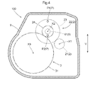
- V indicates the vertical direction of the vehicle drive device 100 mounted on the vehicle.
- the second axis X2 is arranged above both the first axis X1 and the third axis X3.
- the first axis X1 is arranged above the third axis X3
- the second axis X2 is arranged above the first axis X1.
- the configuration in which the pump chamber 62 is formed by the recess formed so that the target surface S of the partition wall 91 is recessed has been described as an example.
- the pump chamber 62 is formed so that the recess formed so that the target surface S of the partition wall 91 is recessed and the surface of the pump cover 63 facing the target surface S are recessed. It may be formed by both the recess and the recess. Alternatively, the recess may not be formed in the partition wall 91, and the pump chamber 62 may be formed by a recess formed so that the surface of the pump cover 63 facing the target surface S is recessed.
- the configuration in which the transmission gear mechanism 2 includes the counter gear mechanism 22 and the pump input shaft 64 is connected so as to rotate integrally with the counter shaft 25 of the counter gear mechanism 22 will be described as an example. did.
- the pump input shaft 64 is connected so as to rotate integrally with any of the plurality of shafts. I just need to be there.
- the pump input shaft 64 may not be connected to the shaft of the transmission gear mechanism 2, but may be connected so as to rotate integrally with the input member 1, for example.
- the target surface S is a surface of the partition wall 91 facing the first accommodation chamber A1, and the pump input shaft 64 is arranged so as to penetrate the partition wall 91 in the axial direction L.
- the configuration has been described as an example. However, without being limited to such a configuration, the target surface S is a surface facing the second accommodating chamber A2 in the partition wall 91 so that the pump input shaft 64 does not penetrate the partition wall 91 in the axial direction L. It may be arranged in.
- the configuration in which the second axis X2 is arranged above both the first axis X1 and the third axis X3 has been described as an example.
- the second axis X2 may be arranged below at least one of the first axis X1 and the third axis X3.
- the partition wall 91 is integrally formed with the first peripheral wall portion 92 and the second peripheral wall portion 94 as an example.
- the partition wall 91 is configured as a separate member from both the first peripheral wall portion 92 and the second peripheral wall portion 94, and is fixed to these by a fixing member such as a bolt. It may be.
- the configuration in which the first peripheral wall portion 92 and the second peripheral wall portion 94 are integrally formed has been described as an example.
- the present invention is not limited to such a configuration, and the first peripheral wall portion 92 and the second peripheral wall portion 94 may be configured by different members.
- the partition wall 91 may be integrally formed with either one of the first peripheral wall portion 92 and the second peripheral wall portion 94, or may be composed of both of them and a separate member.
- the vehicle drive device (100) is A rotary electric machine (MG) that functions as a driving force source for wheels (W), The input member (1) driven and connected to the rotary electric machine (MG) and A pair of output members (4), each of which is driven and connected to the wheel (W), A differential gear mechanism (3) that distributes the rotation transmitted from the rotary electric machine (MG) side to the pair of output members (4).
- a transmission gear mechanism (2) that drives and connects the input member (1) and the differential gear mechanism (3), and
- a hydraulic pump (6) provided with a pump rotor (61) and a pump chamber (62) accommodating the pump rotor (61) and supplying oil to at least the rotary electric machine (MG).
- a rotary electric machine (MG), an input member (1), a differential gear mechanism (3), a transmission gear mechanism (2), and a case (9) for accommodating the hydraulic pump (6) are provided.
- the direction along the rotation axis of the rotary electric machine (MG) is defined as the axial direction (L).
- the case (9) has a first accommodating chamber (A1) accommodating the rotary electric machine (MG) and a second accommodating chamber (A2) accommodating the transmission gear mechanism (2) and the differential gear mechanism (3).
- the pump chamber (62) is formed on the partition wall (91) so as to be located between the first accommodation chamber (A1) and the second accommodation chamber (A2) in the axial direction (L). ing.
- the pump chamber (62) of the hydraulic pump (6) divides the internal space of the case (9) into a first accommodation chamber (A1) and a second accommodation chamber (A2). ) Is formed. Therefore, even if oil leaks from the pump chamber (62), the oil only flows into the first storage chamber (A1) or the second storage chamber (A2) and leaks to the outside of the case (9). I will not put it out.
- the hydraulic pump (6) can be configured in a simple manner.
- the hydraulic pump (6) further includes a pump cover (63) joined to the partition wall (91). It is preferable that the pump chamber (62) is formed between the partition wall (91) and the pump cover (63) in the axial direction (L).
- the hydraulic pump (6) can be configured in a simpler manner while preventing the oil discharged from the hydraulic pump (6) from flowing out to the outside of the case (9).
- the hydraulic pump (6) further includes a pump input shaft (64) connected so as to rotate integrally with the pump rotor (61).
- the pump input shaft (64) is arranged so as to penetrate the partition wall (91) in the axial direction (L), and is attached to the shaft of the transmission gear mechanism (2) in the second accommodating chamber (A2). It is preferable that they are driven and connected.
- the pump input shaft (64) can be rotatably supported with respect to the partition wall (91) of the case (9), and the pump rotor can be rotated by utilizing the rotation of the transmission gear mechanism (2). (61) can be appropriately rotationally driven.
- the transmission gear mechanism (2) is arranged on the first axis (X1) which is the rotation axis of the input member (1), and is connected so as to rotate integrally with the input member (1).
- a first gear (21) and a counter gear mechanism (22) arranged on a second shaft (X2) different from the first shaft (X1) are provided.
- the counter gear mechanism (22) includes a second gear (23) that meshes with the first gear (21), a third gear (24) that rotates integrally with the second gear (23), and the second gear.
- a counter shaft (25) for connecting the gear (23) and the third gear (24) is provided.
- the differential gear mechanism (3) is arranged on a third axis (X3) different from the first axis (X1) and the second axis (X2), and meshes with the third gear (24). Equipped with a gear (31)
- the hydraulic pump (6) further comprises a pump input shaft (64) connected to rotate integrally with the pump rotor (61). It is preferable that the pump input shaft (64) is arranged on the second shaft (X2) and is connected so as to rotate integrally with the counter shaft (25).
- the rotation speed of the counter gear mechanism (22) is generally smaller than the rotation speed of the rotary electric machine (MG). Therefore, according to the configuration in which the hydraulic pump (6) is driven by the rotation of the counter shaft (25) as described above, the pump rotor is compared with the configuration in which the hydraulic pump (6) is driven by the rotary electric machine (MG). The rotation speed of (61) can be reduced. Therefore, the energy loss due to the high-speed rotation of the hydraulic pump (6) can be suppressed to a small value, and the energy efficiency of the vehicle drive device (100) can be improved.
- the fourth gear (31) is arranged so as to scoop up the oil stored inside the case (9).
- the hydraulic pump (6) supplies oil to the rotary electric machine (MG)
- the rotation direction of the pump rotor (61) is set as the normal rotation direction
- the direction opposite to the normal rotation direction is set as the reverse direction.
- It is provided with a supply oil passage (P) for supplying the oil scraped up by the fourth gear (31) to the pump chamber (62) when at least the pump rotor (61) rotates in the reverse direction. Is suitable.
- the pump rotor (61) when the pump rotor (61) rotates in the reverse direction, that is, when the vehicle equipped with the vehicle drive device (100) travels backward, the pump rotor (61) is scraped up by the fourth gear (31).
- the oil is supplied to the pump chamber (62) via the supply oil passage (P).
- the pump rotor (61) rotates in the forward rotation direction, that is, when the vehicle equipped with the vehicle drive device (100) travels forward, the oil stored inside the case (9). Is sucked as the pump rotor (61) rotates and is supplied to the pump chamber (62). Therefore, according to this configuration, the pump rotor (61) can be appropriately lubricated regardless of the traveling state of the vehicle on which the vehicle drive device (100) is mounted.
- the technology according to the present disclosure includes a rotary electric machine that functions as a driving force source for wheels, an input member that is driven and connected to the rotary electric machine, a pair of output members that are driven and connected to the wheels, and a rotary electric machine. It can be used in a vehicle drive device including a differential gear mechanism that distributes the transmitted rotation to a pair of output members, and at least a hydraulic pump that supplies oil to a rotary electric machine.
Landscapes
- Engineering & Computer Science (AREA)
- General Engineering & Computer Science (AREA)
- Mechanical Engineering (AREA)
- Transportation (AREA)
- Chemical & Material Sciences (AREA)
- Combustion & Propulsion (AREA)
- Power Engineering (AREA)
- General Details Of Gearings (AREA)
- Electric Propulsion And Braking For Vehicles (AREA)
- Motor Or Generator Frames (AREA)
- Connection Of Motors, Electrical Generators, Mechanical Devices, And The Like (AREA)
- Cooling, Air Intake And Gas Exhaust, And Fuel Tank Arrangements In Propulsion Units (AREA)
- Arrangement Or Mounting Of Propulsion Units For Vehicles (AREA)
- Hybrid Electric Vehicles (AREA)
Abstract
Description
車輪の駆動力源として機能する回転電機と、
前記回転電機に駆動連結された入力部材と、
それぞれが前記車輪に駆動連結される一対の出力部材と、
前記回転電機の側から伝達される回転を、一対の前記出力部材に分配する差動歯車機構と、
前記入力部材と前記差動歯車機構とを駆動連結する伝達ギヤ機構と、
ポンプロータ、及び当該ポンプロータを収容するポンプ室を備え、少なくとも前記回転電機に油を供給する油圧ポンプと、
前記回転電機、前記入力部材、前記差動歯車機構、前記伝達ギヤ機構、及び前記油圧ポンプを収容するケースと、を備え、
前記回転電機の回転軸に沿う方向を軸方向として、
前記ケースは、前記回転電機を収容する第1収容室と、前記伝達ギヤ機構及び前記差動歯車機構を収容する第2収容室とを、前記軸方向に分ける区画壁を備え、
前記ポンプ室は、前記軸方向における前記第1収容室と前記第2収容室との間に位置するように、前記区画壁に形成されている点にある。
ポンプ室62は、軸方向Lにおける区画壁91とポンプカバー63との間に形成されている。
ポンプ入力軸64は、区画壁91を軸方向Lに貫通するように配置され、第2収容室A2にて伝達ギヤ機構2の軸に駆動連結されている。
カウンタギヤ機構22は、第1ギヤ21に噛み合う第2ギヤ23と、当該第2ギヤ23と一体的に回転する第3ギヤ24と、第2ギヤ23と第3ギヤ24とを連結するカウンタ軸25と、を備え、
差動歯車機構3は、第1軸X1及び第2軸X2とは異なる第3軸X3に配置されて、第3ギヤ24に噛み合う第4ギヤ31を備え、
油圧ポンプ6は、ポンプロータ61と一体的に回転するように連結されたポンプ入力軸64を更に備え、
ポンプ入力軸64は、第2軸X2に配置され、カウンタ軸25と一体的に回転するように連結されている。
油圧ポンプ6が回転電機MGに油を供給する場合におけるポンプロータ61の回転方向を正転方向とし、当該正転方向とは反対方向を逆転方向として、
車両用駆動装置100は、少なくともポンプロータ61が逆転方向に回転する場合に、第4ギヤ31によって掻き上げられた油をポンプ室62へ供給する供給油路Pを備えている。
(1)上記の実施形態では、ポンプ室62が、区画壁91の対象面Sが窪むように形成された凹部によって形成された構成を例として説明した。しかし、そのような構成に限定されることなく、ポンプ室62が、区画壁91の対象面Sが窪むように形成された凹部と、ポンプカバー63における対象面Sに対向する面が窪むように形成された凹部との双方によって形成されていても良い。或いは、区画壁91に上記凹部が形成されず、ポンプ室62が、ポンプカバー63における対象面Sに対向する面が窪むように形成された凹部によって形成されていても良い。
以下では、上記において説明した車両用駆動装置(100)の概要について説明する。
車輪(W)の駆動力源として機能する回転電機(MG)と、
前記回転電機(MG)に駆動連結された入力部材(1)と、
それぞれが前記車輪(W)に駆動連結される一対の出力部材(4)と、
前記回転電機(MG)の側から伝達される回転を、一対の前記出力部材(4)に分配する差動歯車機構(3)と、
前記入力部材(1)と前記差動歯車機構(3)とを駆動連結する伝達ギヤ機構(2)と、
ポンプロータ(61)、及び当該ポンプロータ(61)を収容するポンプ室(62)を備え、少なくとも前記回転電機(MG)に油を供給する油圧ポンプ(6)と、
前記回転電機(MG)、前記入力部材(1)、前記差動歯車機構(3)、前記伝達ギヤ機構(2)、及び前記油圧ポンプ(6)を収容するケース(9)と、を備え、
前記回転電機(MG)の回転軸心に沿う方向を軸方向(L)として、
前記ケース(9)は、前記回転電機(MG)を収容する第1収容室(A1)と、前記伝達ギヤ機構(2)及び前記差動歯車機構(3)を収容する第2収容室(A2)とを、前記軸方向(L)に分ける区画壁(91)を備え、
前記ポンプ室(62)は、前記軸方向(L)における前記第1収容室(A1)と前記第2収容室(A2)との間に位置するように、前記区画壁(91)に形成されている。
前記ポンプ室(62)は、前記軸方向(L)における前記区画壁(91)と前記ポンプカバー(63)との間に形成されていると好適である。
前記ポンプ入力軸(64)は、前記区画壁(91)を前記軸方向(L)に貫通するように配置され、前記第2収容室(A2)にて前記伝達ギヤ機構(2)の軸に駆動連結されていると好適である。
前記カウンタギヤ機構(22)は、前記第1ギヤ(21)に噛み合う第2ギヤ(23)と、前記第2ギヤ(23)と一体的に回転する第3ギヤ(24)と、前記第2ギヤ(23)と前記第3ギヤ(24)とを連結するカウンタ軸(25)と、を備え、
前記差動歯車機構(3)は、前記第1軸(X1)及び前記第2軸(X2)とは異なる第3軸(X3)に配置されて、前記第3ギヤ(24)に噛み合う第4ギヤ(31)を備え、
前記油圧ポンプ(6)は、前記ポンプロータ(61)と一体的に回転するように連結されたポンプ入力軸(64)を更に備え、
前記ポンプ入力軸(64)は、前記第2軸(X2)に配置され、前記カウンタ軸(25)と一体的に回転するように連結されていると好適である。
前記第4ギヤ(31)は、前記ケース(9)の内部に貯留された油を掻き上げるように配置され、
前記油圧ポンプ(6)が前記回転電機(MG)に油を供給する場合における前記ポンプロータ(61)の回転方向を正転方向とし、当該正転方向とは反対方向を逆転方向として、
少なくとも前記ポンプロータ(61)が前記逆転方向に回転する場合に、前記第4ギヤ(31)によって掻き上げられた油を前記ポンプ室(62)へ供給する供給油路(P)を備えていると好適である。
Claims (5)
- 車輪の駆動力源として機能する回転電機と、
前記回転電機に駆動連結された入力部材と、
それぞれが前記車輪に駆動連結される一対の出力部材と、
前記回転電機の側から伝達される回転を、一対の前記出力部材に分配する差動歯車機構と、
前記入力部材と前記差動歯車機構とを駆動連結する伝達ギヤ機構と、
ポンプロータ、及び当該ポンプロータを収容するポンプ室を備え、少なくとも前記回転電機に油を供給する油圧ポンプと、
前記回転電機、前記入力部材、前記差動歯車機構、前記伝達ギヤ機構、及び前記油圧ポンプを収容するケースと、を備え、
前記回転電機の回転軸心に沿う方向を軸方向として、
前記ケースは、前記回転電機を収容する第1収容室と、前記伝達ギヤ機構及び前記差動歯車機構を収容する第2収容室とを、前記軸方向に分ける区画壁を備え、
前記ポンプ室は、前記軸方向における前記第1収容室と前記第2収容室との間に位置するように、前記区画壁に形成されている、車両用駆動装置。 - 前記油圧ポンプは、前記区画壁に接合されたポンプカバーを更に備え、
前記ポンプ室は、前記軸方向における前記区画壁と前記ポンプカバーとの間に形成されている、請求項1に記載の車両用駆動装置。 - 前記油圧ポンプは、前記ポンプロータと一体的に回転するように連結されたポンプ入力軸を更に備え、
前記ポンプ入力軸は、前記区画壁を前記軸方向に貫通するように配置され、前記第2収容室にて前記伝達ギヤ機構の軸に駆動連結されている、請求項1又は2に記載の車両用駆動装置。 - 前記伝達ギヤ機構は、前記入力部材の回転軸心である第1軸に配置されて、前記入力部材と一体的に回転するように連結された第1ギヤと、前記第1軸とは異なる第2軸に配置されたカウンタギヤ機構と、を備え、
前記カウンタギヤ機構は、前記第1ギヤに噛み合う第2ギヤと、前記第2ギヤと一体的に回転する第3ギヤと、前記第2ギヤと前記第3ギヤとを連結するカウンタ軸と、を備え、
前記差動歯車機構は、前記第1軸及び前記第2軸とは異なる第3軸に配置されて、前記第3ギヤに噛み合う第4ギヤを備え、
前記油圧ポンプは、前記ポンプロータと一体的に回転するように連結されたポンプ入力軸を更に備え、
前記ポンプ入力軸は、前記第2軸に配置され、前記カウンタ軸と一体的に回転するように連結されている、請求項1から3のいずれか一項に記載の車両用駆動装置。 - 前記第4ギヤは、前記ケースの内部に貯留された油を掻き上げるように配置され、
前記油圧ポンプが前記回転電機に油を供給する場合における前記ポンプロータの回転方向を正転方向とし、当該正転方向とは反対方向を逆転方向として、
少なくとも前記ポンプロータが前記逆転方向に回転する場合に、前記第4ギヤによって掻き上げられた油を前記ポンプ室へ供給する供給油路を備える、請求項4に記載の車両用駆動装置。
Priority Applications (4)
| Application Number | Priority Date | Filing Date | Title |
|---|---|---|---|
| EP21872540.6A EP4167444B1 (en) | 2020-09-25 | 2021-09-24 | Vehicle drive device |
| JP2022552059A JP7380903B2 (ja) | 2020-09-25 | 2021-09-24 | 車両用駆動装置 |
| CN202180064467.0A CN116210138B (zh) | 2020-09-25 | 2021-09-24 | 车用驱动装置 |
| US18/012,169 US11906024B2 (en) | 2020-09-25 | 2021-09-24 | Vehicle drive device |
Applications Claiming Priority (2)
| Application Number | Priority Date | Filing Date | Title |
|---|---|---|---|
| JP2020161130 | 2020-09-25 | ||
| JP2020-161130 | 2020-09-25 |
Publications (1)
| Publication Number | Publication Date |
|---|---|
| WO2022065411A1 true WO2022065411A1 (ja) | 2022-03-31 |
Family
ID=80846539
Family Applications (1)
| Application Number | Title | Priority Date | Filing Date |
|---|---|---|---|
| PCT/JP2021/034991 Ceased WO2022065411A1 (ja) | 2020-09-25 | 2021-09-24 | 車両用駆動装置 |
Country Status (5)
| Country | Link |
|---|---|
| US (1) | US11906024B2 (ja) |
| EP (1) | EP4167444B1 (ja) |
| JP (1) | JP7380903B2 (ja) |
| CN (1) | CN116210138B (ja) |
| WO (1) | WO2022065411A1 (ja) |
Cited By (3)
| Publication number | Priority date | Publication date | Assignee | Title |
|---|---|---|---|---|
| WO2024110512A1 (de) * | 2022-11-24 | 2024-05-30 | Zf Friedrichshafen Ag | Elektrische antriebsanordnung sowie verfahren zur steuerung der antriebsanordnung |
| WO2024166357A1 (ja) * | 2023-02-10 | 2024-08-15 | 株式会社ジェイテクト | 転がり軸受装置 |
| EP4575270A4 (en) * | 2022-10-07 | 2025-10-22 | Aisin Corp | Vehicular drive device |
Families Citing this family (3)
| Publication number | Priority date | Publication date | Assignee | Title |
|---|---|---|---|---|
| CN112074673B (zh) * | 2018-04-26 | 2023-05-23 | 本田技研工业株式会社 | 车辆用动力单元 |
| DE102023136123A1 (de) * | 2023-12-20 | 2025-06-26 | Valeo Eautomotive Germany Gmbh | Elektrische Antriebsvorrichtung für ein Fahrzeug |
| US12222030B1 (en) * | 2024-03-14 | 2025-02-11 | Schaeffler Technologies AG & Co. KG | Electric drive unit |
Citations (5)
| Publication number | Priority date | Publication date | Assignee | Title |
|---|---|---|---|---|
| JP2011259590A (ja) * | 2010-06-08 | 2011-12-22 | Aisin Aw Co Ltd | 車両用駆動装置 |
| WO2019098322A1 (ja) * | 2017-11-17 | 2019-05-23 | アイシン・エィ・ダブリュ株式会社 | 車両用駆動装置 |
| JP2019129608A (ja) | 2018-01-24 | 2019-08-01 | トヨタ自動車株式会社 | 車両用駆動装置 |
| US20190291570A1 (en) * | 2018-03-23 | 2019-09-26 | Sf Motors, Inc. | Dual loop liquid cooling of integrated electric drivetrain |
| JP2020148150A (ja) * | 2019-03-13 | 2020-09-17 | トヨタ自動車株式会社 | 車両用油供給装置の制御装置 |
Family Cites Families (11)
| Publication number | Priority date | Publication date | Assignee | Title |
|---|---|---|---|---|
| JP4201282B2 (ja) * | 2006-03-23 | 2008-12-24 | トヨタ自動車株式会社 | 車両用駆動装置 |
| JP4369966B2 (ja) * | 2007-07-18 | 2009-11-25 | アイシン・エィ・ダブリュ株式会社 | ハイブリッド車両用駆動装置 |
| JP4485566B2 (ja) * | 2007-11-13 | 2010-06-23 | 本田技研工業株式会社 | モータ式動力装置 |
| US8049384B2 (en) * | 2009-06-19 | 2011-11-01 | GM Global Technology Operations LLC | Electronic drive unit |
| CN102362100B (zh) * | 2009-09-25 | 2014-04-16 | 爱信艾达株式会社 | 驱动装置 |
| JP2012086827A (ja) * | 2010-09-24 | 2012-05-10 | Aisin Aw Co Ltd | 車両用駆動装置 |
| JP2013053737A (ja) * | 2011-09-06 | 2013-03-21 | Honda Motor Co Ltd | 遊星歯車機構の支持構造 |
| JP6048347B2 (ja) * | 2013-08-29 | 2016-12-21 | アイシン・エィ・ダブリュ株式会社 | 車両用駆動装置 |
| JP2016063689A (ja) * | 2014-09-19 | 2016-04-25 | Ntn株式会社 | インホイールモータ駆動装置 |
| DE112017003474B4 (de) * | 2016-09-30 | 2024-05-23 | Aisin Corporation | Fahrzeugantriebsgerät |
| WO2019194070A1 (ja) * | 2018-04-06 | 2019-10-10 | 日本電産株式会社 | モータユニット |
-
2021
- 2021-09-24 CN CN202180064467.0A patent/CN116210138B/zh active Active
- 2021-09-24 EP EP21872540.6A patent/EP4167444B1/en active Active
- 2021-09-24 JP JP2022552059A patent/JP7380903B2/ja active Active
- 2021-09-24 WO PCT/JP2021/034991 patent/WO2022065411A1/ja not_active Ceased
- 2021-09-24 US US18/012,169 patent/US11906024B2/en active Active
Patent Citations (5)
| Publication number | Priority date | Publication date | Assignee | Title |
|---|---|---|---|---|
| JP2011259590A (ja) * | 2010-06-08 | 2011-12-22 | Aisin Aw Co Ltd | 車両用駆動装置 |
| WO2019098322A1 (ja) * | 2017-11-17 | 2019-05-23 | アイシン・エィ・ダブリュ株式会社 | 車両用駆動装置 |
| JP2019129608A (ja) | 2018-01-24 | 2019-08-01 | トヨタ自動車株式会社 | 車両用駆動装置 |
| US20190291570A1 (en) * | 2018-03-23 | 2019-09-26 | Sf Motors, Inc. | Dual loop liquid cooling of integrated electric drivetrain |
| JP2020148150A (ja) * | 2019-03-13 | 2020-09-17 | トヨタ自動車株式会社 | 車両用油供給装置の制御装置 |
Non-Patent Citations (1)
| Title |
|---|
| See also references of EP4167444A4 |
Cited By (3)
| Publication number | Priority date | Publication date | Assignee | Title |
|---|---|---|---|---|
| EP4575270A4 (en) * | 2022-10-07 | 2025-10-22 | Aisin Corp | Vehicular drive device |
| WO2024110512A1 (de) * | 2022-11-24 | 2024-05-30 | Zf Friedrichshafen Ag | Elektrische antriebsanordnung sowie verfahren zur steuerung der antriebsanordnung |
| WO2024166357A1 (ja) * | 2023-02-10 | 2024-08-15 | 株式会社ジェイテクト | 転がり軸受装置 |
Also Published As
| Publication number | Publication date |
|---|---|
| EP4167444B1 (en) | 2025-07-02 |
| EP4167444A1 (en) | 2023-04-19 |
| JPWO2022065411A1 (ja) | 2022-03-31 |
| US20230258250A1 (en) | 2023-08-17 |
| CN116210138A (zh) | 2023-06-02 |
| CN116210138B (zh) | 2026-01-06 |
| JP7380903B2 (ja) | 2023-11-15 |
| US11906024B2 (en) | 2024-02-20 |
| EP4167444A4 (en) | 2024-04-24 |
Similar Documents
| Publication | Publication Date | Title |
|---|---|---|
| JP7380903B2 (ja) | 車両用駆動装置 | |
| JP6852810B2 (ja) | 車両用駆動装置 | |
| US8049384B2 (en) | Electronic drive unit | |
| CN112141074B (zh) | 混合动力车辆 | |
| JP5747779B2 (ja) | 動力伝達装置の潤滑装置 | |
| JP4234947B2 (ja) | 油圧発生装置用の駆動装置 | |
| US11608884B2 (en) | Vehicle drive device | |
| CN113272168A (zh) | 车辆用驱动装置 | |
| JP2019094933A (ja) | 車両用駆動装置 | |
| WO2019177020A1 (ja) | 車両用駆動装置 | |
| JP2017133564A (ja) | 車両用モータ駆動装置 | |
| JP7280723B2 (ja) | 車両用駆動伝達装置 | |
| JP2021008249A (ja) | インホイールモータ型の車両駆動装置 | |
| JP5541012B2 (ja) | 動力伝達装置のオイルポンプ構造およびポンプカバーの加工方法 | |
| JP4858783B2 (ja) | 流体ポンプ及び車両用駆動装置 | |
| JP7241670B2 (ja) | 車両用駆動伝達装置 | |
| WO2020203916A1 (ja) | 車両用駆動装置 | |
| WO2019177015A1 (ja) | 車両用駆動装置 | |
| US11897328B2 (en) | Electric drive apparatus for vehicle | |
| JP2021160466A (ja) | 車両用駆動装置 | |
| WO2024203568A1 (ja) | 車両用駆動装置 | |
| JP2012166738A (ja) | 車両用駆動装置 | |
| JP2020022344A (ja) | 回転電機の冷却構造及び車両用駆動装置 | |
| JP2009127424A (ja) | 潤滑油の圧送機構及び該圧送機構を有するスクリュ圧縮機 | |
| JP2022107400A (ja) | 車両用駆動装置 |
Legal Events
| Date | Code | Title | Description |
|---|---|---|---|
| 121 | Ep: the epo has been informed by wipo that ep was designated in this application |
Ref document number: 21872540 Country of ref document: EP Kind code of ref document: A1 |
|
| ENP | Entry into the national phase |
Ref document number: 2022552059 Country of ref document: JP Kind code of ref document: A |
|
| ENP | Entry into the national phase |
Ref document number: 2021872540 Country of ref document: EP Effective date: 20230116 |
|
| NENP | Non-entry into the national phase |
Ref country code: DE |
|
| WWG | Wipo information: grant in national office |
Ref document number: 2021872540 Country of ref document: EP |