WO2022067749A1 - 一种分集通信的方法及装置 - Google Patents
一种分集通信的方法及装置 Download PDFInfo
- Publication number
- WO2022067749A1 WO2022067749A1 PCT/CN2020/119632 CN2020119632W WO2022067749A1 WO 2022067749 A1 WO2022067749 A1 WO 2022067749A1 CN 2020119632 W CN2020119632 W CN 2020119632W WO 2022067749 A1 WO2022067749 A1 WO 2022067749A1
- Authority
- WO
- WIPO (PCT)
- Prior art keywords
- frequency domain
- domain resources
- modulation symbols
- antenna port
- mapping
- Prior art date
- Legal status (The legal status is an assumption and is not a legal conclusion. Google has not performed a legal analysis and makes no representation as to the accuracy of the status listed.)
- Ceased
Links
Images


Classifications
-
- H—ELECTRICITY
- H04—ELECTRIC COMMUNICATION TECHNIQUE
- H04L—TRANSMISSION OF DIGITAL INFORMATION, e.g. TELEGRAPHIC COMMUNICATION
- H04L5/00—Arrangements affording multiple use of the transmission path
- H04L5/0001—Arrangements for dividing the transmission path
- H04L5/0014—Three-dimensional division
- H04L5/0023—Time-frequency-space
-
- H—ELECTRICITY
- H04—ELECTRIC COMMUNICATION TECHNIQUE
- H04B—TRANSMISSION
- H04B7/00—Radio transmission systems, i.e. using radiation field
- H04B7/02—Diversity systems; Multi-antenna system, i.e. transmission or reception using multiple antennas
- H04B7/04—Diversity systems; Multi-antenna system, i.e. transmission or reception using multiple antennas using two or more spaced independent antennas
- H04B7/0413—MIMO systems
- H04B7/0456—Selection of precoding matrices or codebooks, e.g. using matrices antenna weighting
-
- H—ELECTRICITY
- H04—ELECTRIC COMMUNICATION TECHNIQUE
- H04L—TRANSMISSION OF DIGITAL INFORMATION, e.g. TELEGRAPHIC COMMUNICATION
- H04L27/00—Modulated-carrier systems
- H04L27/26—Systems using multi-frequency codes
- H04L27/2601—Multicarrier modulation systems
-
- H—ELECTRICITY
- H04—ELECTRIC COMMUNICATION TECHNIQUE
- H04L—TRANSMISSION OF DIGITAL INFORMATION, e.g. TELEGRAPHIC COMMUNICATION
- H04L27/00—Modulated-carrier systems
- H04L27/32—Carrier systems characterised by combinations of two or more of the types covered by groups H04L27/02, H04L27/10, H04L27/18 or H04L27/26
- H04L27/34—Amplitude- and phase-modulated carrier systems, e.g. quadrature-amplitude modulated carrier systems
- H04L27/3405—Modifications of the signal space to increase the efficiency of transmission, e.g. reduction of the bit error rate, bandwidth, or average power
- H04L27/3411—Modifications of the signal space to increase the efficiency of transmission, e.g. reduction of the bit error rate, bandwidth, or average power reducing the peak to average power ratio or the mean power of the constellation; Arrangements for increasing the shape gain of a signal set
-
- H—ELECTRICITY
- H04—ELECTRIC COMMUNICATION TECHNIQUE
- H04L—TRANSMISSION OF DIGITAL INFORMATION, e.g. TELEGRAPHIC COMMUNICATION
- H04L5/00—Arrangements affording multiple use of the transmission path
- H04L5/003—Arrangements for allocating sub-channels of the transmission path
- H04L5/0044—Allocation of payload; Allocation of data channels, e.g. PDSCH or PUSCH
-
- H—ELECTRICITY
- H04—ELECTRIC COMMUNICATION TECHNIQUE
- H04L—TRANSMISSION OF DIGITAL INFORMATION, e.g. TELEGRAPHIC COMMUNICATION
- H04L27/00—Modulated-carrier systems
- H04L27/26—Systems using multi-frequency codes
- H04L27/2601—Multicarrier modulation systems
- H04L27/2602—Signal structure
-
- H—ELECTRICITY
- H04—ELECTRIC COMMUNICATION TECHNIQUE
- H04L—TRANSMISSION OF DIGITAL INFORMATION, e.g. TELEGRAPHIC COMMUNICATION
- H04L27/00—Modulated-carrier systems
- H04L27/26—Systems using multi-frequency codes
- H04L27/2601—Multicarrier modulation systems
- H04L27/2614—Peak power aspects
Definitions
- the embodiments of the present application relate to the field of wireless communication technologies, and in particular, to a method and apparatus for diversity communication.
- multipath fading may occur in the signal transmitted between the terminal and the base station, resulting in poor quality of the signal received by the receiving end, or inability to receive the signal.
- terminals often work in urban buildings or other complex geographic environments, and the speed and direction of movement are arbitrary.
- the signal sent by the transmitting end goes through propagation paths such as reflection and scattering, the signal reaching the receiving end is often the superposition of multiple signals with different amplitudes and phases, so that the amplitude of the received signal appears. Random fluctuations, forming multipath fading.
- the received signal amplitude will be reduced.
- changes in meteorological conditions can also affect the propagation of the signal, causing changes in the amplitude and phase of the received signal.
- Diversity techniques can be used to improve the received signal quality.
- Diversity techniques can utilize multiple paths to transmit signals that transmit the same information and have approximately equal average signal strength and independent fading characteristics. After receiving these signals, the receiving end can appropriately combine these signals, so as to greatly reduce the influence of multipath fading, thereby improving the reliability of transmission.
- the present application provides a diversity communication method to propose a diversity transmission scheme.
- a method for diversity communication maps multiple modulation symbols to multiple antenna ports; in each mapping, multiple consecutive modulation symbols are mapped to one antenna port; the multiple modulation symbols are generated based on one transport block. Then, the first device performs the following processing on the modulation symbols on each antenna port: mapping multiple modulation symbols to frequency domain resources, where the frequency domain resources are frequency domain resources corresponding to the antenna ports, and different antenna ports correspond to The frequency domain resources do not overlap.
- one transmission block is transmitted on different antenna ports, and the frequency domain resources corresponding to different antenna ports do not overlap, that is, one transmission block is transmitted on different channels, so this transmission block achieves diversity transmission. Purpose.
- the modulation symbols are mapped to the antenna ports, multiple consecutive modulation symbols are mapped each time. This mapping method can keep the phase difference between the multiple consecutive modulation symbols from being destroyed, so that the communication system can Keep the peak to average power ratio (PAPR) low.
- PAPR peak to average power ratio
- each mapping an even number of consecutive modulation symbols are mapped to one antenna port.
- the multiple antenna ports include a first antenna port and a second antenna port, two consecutive modulation symbols are mapped to one antenna port; specifically, the following formula can be used to map multiple modulation symbols to multiple antenna ports superior:
- x (0) is the first antenna port
- x (1) is the second antenna port
- d (0) is the modulation symbol
- i, 4i, 4i+1, 4i+2 and 4i+3 are the modulation symbol numbers
- i is an integer greater than or equal to 0.
- the first device may modulate multiple bits encoded in one transport block to obtain multiple modulation symbols.
- the first device may Discrete Fourier Transform (discrete fourier transformation, DFT). If DFT is not performed, the final result is Orthogonal Frequency Division Multiplexing (OFDM) signal. If DFT is performed, the final result is Discrete Fourier Transform Extended Orthogonal Frequency Division Multiplexing (DFT-s- OFDM) signal.
- DFT discrete Fourier Transform
- OFDM Orthogonal Frequency Division Multiplexing
- DFT-s- OFDM Discrete Fourier Transform Extended Orthogonal Frequency Division Multiplexing
- a method for diversity communication processes one transport block to generate multiple codewords. Wherein, different codewords correspond to different antenna ports, and different antenna ports correspond to non-overlapping frequency domain resources. Then, the first device performs the following processing on each codeword: modulate the bits in the codeword to obtain multiple modulation symbols, and map the multiple modulation symbols to frequency domain resources, the frequency domain resources is the frequency domain resource corresponding to the antenna port.
- different codewords generated by a transport block are transmitted on different antenna ports, the frequency domain resources corresponding to different antenna ports do not overlap, and different codewords experience different channels, that is, a transport block is in the It is transmitted on different channels, so this transmission block achieves the purpose of diversity transmission.
- each codeword can be decoded independently, even if one antenna at the receiving end experiences severe fading (for example, is blocked), the receiving end can recover the transmission block of the first device through the data received by other antennas .
- a codeword is a redundant version of the transport block.
- Different codewords can be the same redundancy version or different redundancy versions of the same transport block.
- the combined reception gain of different redundancy versions is greater than the combined reception gain of the same version.
- the first device may first perform discrete Fourier transform DFT on the plurality of modulation symbols. If the DFT is not performed, the OFDM signal is finally obtained. If the DFT is performed, the final result is the discrete Fourier transform extended OFDM DFT-s-OFDM signal.
- the frequency domain resources corresponding to each antenna port are discontinuous; or, the frequency domain resources corresponding to each antenna port are continuous.
- the frequency domain resources corresponding to each antenna port when the frequency domain resources corresponding to each antenna port are discontinuous, it includes any one of the following: the frequency domain resources include multiple resource elements (resource elements, RE), the multiple resource elements The REs are not consecutive; the REs in this application can also be replaced by subcarriers.
- the frequency domain resources include multiple resource elements (resource elements, RE), the multiple resource elements
- REs resource elements
- the REs are not consecutive; the REs in this application can also be replaced by subcarriers.
- the frequency domain resources include multiple precoding resource block groups (precoding resource block groups, PRGs), and the multiple precoding resource block groups PRGs are discontinuous; the frequency domain resources include multiple physical resource blocks (physical resource blocks). , PRB), the PRBs of the multiple physical resource blocks are discontinuous.
- the discontinuous (spaced) portion is the frequency domain resource of an additional antenna port.
- the first device may further receive a first indication, where the first indication is used to indicate a mapping manner for mapping multiple modulation symbols to frequency domain resources. For example, when 4 mapping modes are included, the first indication can use 2 bits to display the indicating mapping modes, and 00, 01, 10, and 11 respectively represent 4 different mapping modes.
- the first device may also receive one or more demodulation reference signal (de-modulation reference signal, DMRS) port identifiers.
- demodulation reference signal demodulation reference signal, DMRS
- the frequency domain resource includes multiple discontinuous resource elements RE (subcarriers); it can also be understood as: the first device is in The mapping method adopted for mapping the multiple modulation symbols to the frequency domain resources of the antenna port is: mapping the multiple modulation symbols to multiple discontinuous REs or subcarriers.
- the frequency domain resources corresponding to each antenna port are continuous; or, the frequency domain resources include multiple discontinuous precoding resource block groups PRG; or, the frequency domain resources
- the resource includes multiple discontinuous physical resource blocks PRB; it can also be understood as: the mapping method adopted by the first device for mapping multiple modulation symbols to the frequency domain resources of the antenna port is: mapping multiple modulation symbols to On the continuous frequency domain resources corresponding to the antenna ports; or, mapping multiple modulation symbols to multiple discontinuous PRGs; or, mapping multiple modulation symbols to multiple discontinuous PRBs.
- the first device may further receive information of one or more subbands, where the information of the subbands is used to determine the frequency domain resource corresponding to the antenna port.
- the information of the subband can be used to indicate the frequency domain position of the subband, or to indicate the bandwidth of the subband.
- the frequency domain resources corresponding to each antenna port are continuous; it can also be understood as: the first device is mapping multiple modulation symbols to the antenna ports When it is on the frequency domain resources of the antenna port, the mapping method adopted is: mapping a plurality of modulation symbols to the continuous frequency domain resources corresponding to the antenna ports. It may also be said that the first device uses a subband mapping manner to map the plurality of modulation symbols to frequency domain resources. Even if the first device only receives the information of one subband, the first device can deduce the frequency domain position of another subband according to a certain rule.
- the first device may further process the frequency-domain signal after the frequency-domain resource mapping to obtain an OFDM signal or a discrete Fourier transform-extended orthogonal frequency-division multiplexing (DFT) signal.
- DFT discrete Fourier transform-extended orthogonal frequency-division multiplexing
- -s-OFDM discrete Fourier transform-extended orthogonal frequency-division multiplexing
- a communication device in a third aspect, has the functions of implementing the first aspect and any possible implementation of the first aspect, or implementing the second aspect and any possible implementation of the second aspect.
- These functions can be implemented by hardware or by executing corresponding software by hardware.
- the hardware or software includes one or more functional modules corresponding to the above-mentioned functions.
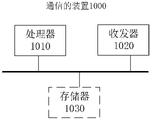
- a communication device comprising a processor and a memory; the memory is used to store computer program instructions; the processor is used to execute part or all of the computer program instructions in the memory, when all When some or all of the computer program instructions are executed, they are used to implement the function of the first device in the method of the above-mentioned first aspect and any possible implementation of the first aspect, or to realize any possible implementation of the above-mentioned second aspect and the second aspect.
- the function of the first device in the implementation.
- the apparatus may further include a transceiver configured to transmit a signal processed by the processor or receive a signal input to the processor.
- the transceiver may perform the sending action or the receiving action performed by the first device in the first aspect and any possible implementation of the first aspect; or, perform the second aspect and any possible implementation of the second aspect by the first device. send action or receive action.
- the present application provides a chip system, the chip system includes one or more processors (which may also be referred to as processing circuits), and the processors are electrically coupled with a memory (which may also be referred to as a storage medium). ; the memory may be located in the chip system or not in the chip system; the memory is used to store computer program instructions; the processor is used to execute part or all of the computer in the memory Program instructions, when some or all of the computer program instructions are executed, are used to implement the functions of the first device in the above-mentioned first aspect and any possible implementation method of the first aspect, or to implement the above-mentioned second aspects and second aspects. The function of the first device in any possible implementation of the aspect.
- the chip system may further include an input-output interface, where the input-output interface is configured to output a signal processed by the processor, or receive a signal input to the processor.
- the input/output interface may perform the sending action or the receiving action performed by the first device in the first aspect and any possible implementation of the first aspect; or, perform the first device in the second aspect and any possible implementation of the second aspect. The send action or receive action performed.
- the chip system may be composed of chips, or may include chips and other discrete devices.
- a sixth aspect provides a computer-readable storage medium for storing a computer program, the computer program comprising instructions for implementing the functions in the first aspect and any possible implementation of the first aspect, or for implementing Instructions for functions in the second aspect and any possible implementation of the second aspect.
- a computer-readable storage medium is used to store a computer program, and when the computer program is executed by a computer, it can cause the computer to execute the first aspect and the first device in the method for any possible implementation of the first aspect The method performed, or the method performed by the first device in the second aspect and any possible implementation of the second aspect.
- a computer program product comprising: computer program code, when the computer program code is run on a computer, the computer is made to execute the first aspect and any possible possibility of the first aspect.
- the method performed by the first device in the implementation, or the method performed by the first device in any possible implementation of the second aspect and the second aspect is performed.
- FIG. 1 is a schematic diagram of a communication system in an embodiment of the application
- FIG. 2 is a schematic diagram of a process of short-delay cyclic delay diversity SD-CDD diversity communication in an embodiment of the application;
- FIG. 3 is a schematic diagram of a process of diversity communication in an embodiment of the application.
- FIG. 4a and FIG. 4b are respectively schematic diagrams of an antenna port mapping in an embodiment of the present application.
- FIG. 5a is a schematic diagram of a RE comb mapping manner in an embodiment of the present application.
- FIG. 5b is a schematic diagram of a precoding resource block group PRG/physical resource block PRB interleaving and mapping manner in an embodiment of the present application;
- FIG. 5c is a schematic diagram of a subband mapping manner in an embodiment of the present application.
- 5d is a schematic diagram of a time-frequency resource grid after RE comb mapping in an embodiment of the present application
- FIG. 5e is a schematic diagram of a time-frequency resource grid after subband mapping in an embodiment of the present application.
- 5f is a schematic diagram of continuous or discontinuous frequency domain ranges of two subbands in an embodiment of the present application.
- FIG. 6 is a schematic diagram of a process of diversity communication in an embodiment of the application.
- FIG. 7 is a schematic diagram of a process of diversity communication in an embodiment of the application.
- FIG. 8 is a schematic diagram of a mapping relationship between a frequency domain port and a time domain resource in an embodiment of the present application
- FIG. 9 is a structural diagram of an apparatus for diversity communication according to an embodiment of the application.
- FIG. 10 is a structural diagram of an apparatus for diversity communication according to an embodiment of the application.
- FIG. 11 is a device structure diagram of a terminal according to an embodiment of the present application.
- system architecture of the diversity communication method provided by the embodiments of the present application. It is understandable that the system architecture described in the embodiments of the present application is to more clearly describe the technical solutions of the embodiments of the present application, and does not constitute a limitation on the technical solutions provided by the embodiments of the present application.
- WLAN wireless local area network
- LTE long term evolution
- LTE frequency division duplex frequency division duplex
- FDD frequency division duplex
- TDD time division duplex
- UMTS universal mobile telecommunication system
- WiMAX worldwide interoperability for microwave access
- 5G fifth generation
- NR new radio
- the communication system shown in FIG. 1 includes a network device and a terminal, and air interface resources can be used for wireless communication between the network device and the terminal.
- the air interface resources may include one or more of time domain resources, frequency domain resources, code domain resources and air domain resources.
- the present application can also be applied to a communication system between terminals, or a communication system between network devices and network devices.
- FIG. 2 a schematic diagram of a process of short delay cyclic delay diversity (small delay-cyclic delay diversity, SD-CDD) diversity communication is provided, which specifically includes the following steps:
- Step 201 Modulate the coded bits of the transport block to obtain a plurality of modulated symbols, which may be referred to as modulation symbols, and the modulation symbols may also be referred to as complex symbols.
- Step 202 Perform discrete Fourier transform DFT on a plurality of modulation symbols.
- the DFT operation may also be referred to as transform domain precoding. This step 202 is optional. If DFT is not performed, the OFDM signal is finally obtained; if DFT is performed, the DFT-s-OFDM signal is finally obtained.
- Each symbol after the DFT can be called a sample, or a complex sample or a complex symbol, etc.
- Step 203 Precoding the DFT symbols.
- the precoding here may be precoding for non-codebook transmission or precoding for codebook transmission.
- Step 204 Map the precoded symbols to two antenna ports, where the symbols mapped to the two antenna ports are the same.
- SD-CDD operates on one of the antennas, typically resulting in a time-domain (cyclic) shift equivalent to frequency-domain weighting.
- two antenna ports are used as an example for illustration. In practical applications, there may be more antenna ports, such as 4, 8, and so on.
- the symbols obtained in step 202 may be directly mapped to multiple antenna ports without precoding in step 203, so step 203 is optional.
- Step 205 Map the symbols on each antenna port to the frequency domain resources corresponding to the antenna port, that is, perform subcarrier mapping. It should be noted that the frequency domain resources corresponding to the two antenna ports are the same.
- Step 206 Perform inverse fast Fourier transform (IFFT, IFFT) and add cyclic prefix (cyclic prefix, CP) operations on the frequency domain signal after the frequency domain resource mapping to obtain a DFT-s-OFDM signal or OFDM signal.
- IFFT inverse fast Fourier transform
- CP cyclic prefix
- the two signals are exactly the same, although the SD-CDD operation is performed in step 204, and the two signals are sent out in tandem.
- the time domain resources occupied by the two signals are still the same, and the one after the other here is not caused by different time domain resources, but caused by different sampling points.
- the principle of SD-CDD acquisition diversity is to transmit signals at different times through multi-antenna ports to increase the frequency selectivity of the channel, so that the receiver can obtain greater frequency domain diversity gain.
- SD-CDD converts antenna diversity into frequency domain diversity.
- the SD-CDD technology also has some shortcomings.
- the performance gain depends on the channel conditions. When the frequency selectivity of the channel itself is strong, the gain obtained by SD-CDD is small. For another example, the gain obtained under the DFT-s-OFDM waveform is small. For another example, when the bandwidth is small, the space for cyclic shift is small, and it is difficult to obtain the gain.
- SD-CDD increases the delay spread of the channel, which leads to the deterioration of the channel estimation performance.
- this application proposes a variety of diversity communication schemes.
- the diversity scheme proposed in this application can obtain transmit antenna port diversity gain under both OFDM and DFT-s-OFDM waveforms, and the proposed scheme is subject to channel conditions and bandwidth. and other factors are less affected. It can provide stable diversity income in various application scenarios.
- Network equipment with equipment capable of providing random access functions for terminal equipment or a chip that can be provided in the equipment, the equipment includes but is not limited to: evolved Node B (evolved Node B, eNB), radio network controller ( radio network controller, RNC), Node B (Node B, NB), base station controller (BSC), base transceiver station (base transceiver station, BTS), home base station (for example, home evolved NodeB, or home Node B, HNB), baseband unit (BBU), access point (AP), wireless relay node, wireless backhaul node, transmission point (transmission point) in wireless fidelity (wireless fidelity, WIFI) system and reception point, TRP or transmission point, TP), etc., can also be 5G, such as NR, gNB in the system, or transmission point (TRP or TP), one or a group of base stations in the 5G system (including multiple antenna panel), or, it can also be a network node that constitutes a gNB or a transmission point, such
- Terminal equipment also known as user equipment (UE), mobile station (MS), mobile terminal (MT), terminal, etc.
- UE user equipment
- MS mobile station
- MT mobile terminal
- the terminal device includes a handheld device with a wireless connection function, a vehicle-mounted device, and the like.
- terminal devices can be: mobile phones (mobile phones), tablet computers, notebook computers, PDAs, mobile Internet devices (MIDs), wearable devices, virtual reality (virtual reality, VR) devices, augmented reality (augmented reality (AR) equipment, wireless terminals in industrial control, wireless terminals in self-driving, wireless terminals in remote medical surgery, and smart grids wireless terminal, wireless terminal in transportation safety, wireless terminal in smart city, wireless terminal in smart home, or vehicle-to-vehicle (Vehicle-to-Vehicle, V2V) public wireless terminals, etc.
- VR virtual reality
- AR augmented reality
- wireless terminals in industrial control wireless terminals in self-driving
- smart grids wireless terminal in transportation safety, wireless terminal in smart city, wireless terminal in smart home, or vehicle-to-vehicle (Vehicle-to-Vehicle, V2V) public wireless terminals, etc.
- Diversity techniques are the use of multiple signal paths to transmit information, and these signals are appropriately combined at the receiving end to greatly reduce the influence of multipath fading, thereby improving the reliability of transmission.
- the multiple signal paths have the characteristics of transmitting the same information, having approximately equal average signal strength, and fading independently of each other. Simply put, if one path has experienced deep fading, another relatively independent path may still contain a stronger signal, so two or more of the multiple signals can be selected to combine, so that the Improve the instantaneous signal-to-noise ratio and average signal-to-noise ratio of the receiver.
- An antenna refers to a device that can effectively radiate electromagnetic waves to a specific direction in space or can effectively receive electromagnetic waves from a specific direction in space.
- Antenna ports in 3GPP protocols 36.211 (LTE) and 38.211 (NR) are defined as: the channel experienced by one antenna port transmitting a symbol can be derived from the channel experienced by another symbol propagating on the same antenna.
- Antenna ports in 3GPP may also be referred to as logical antenna ports. There are multiple implementation possibilities for the correspondence between antenna ports and physical antennas:
- One possibility is that the number of antenna ports and physical antennas are equal and correspond one-to-one;
- the number of antenna ports and physical antennas are equal but not in one-to-one correspondence, for example, the antenna port signals are mapped to physical antennas after precoding;
- the number of antenna ports is less than the number of physical antennas.
- one antenna port may correspond to an array of multiple physical antennas.
- the antenna port mentioned in this application is similar to the antenna port defined by the 3GPP protocol, and can be regarded as a method for identifying the channel.
- the antenna port in this application may be a physical antenna port or a logical antenna port.
- one logical antenna port corresponds to one or more physical antenna ports, and different logical antenna ports correspond to different physical antenna ports, allowing physical antenna ports corresponding to different logical antenna ports The antenna ports are crossed.
- Redundancy version In order to support hybrid automatic repeat request (HARQ) based on incremental redundancy (IR), LTE and NR support redundancy version mechanism.
- HARQ hybrid automatic repeat request
- IR incremental redundancy
- LTE and NR support redundancy version mechanism.
- the channel coding processing flow of NR is first introduced: the UE or the base station generates a transport block (TB) to be transmitted, and a TB contains several bits to be transmitted.
- TB transport block
- the transmitter first performs TB CRC addition, followed by code block division and code block-level CRC addition; after that, the transmitter performs LDPC encoding on each code block (in LTE, the transmitter performs turbo encoding, and in other communication systems , the transmitter can also use other coding methods such as polar (polar code); after LDPC coding, the transmitter performs rate matching according to the redundancy version ID (rv_id) to generate different coding block redundancy versions. Different redundant versions of the same TB or CB have different contents, but all contain the information of the original TB or CB.
- the redundant version can be called the redundant version of TB, the redundant version of CB, or the redundant version of codeword (CW); multiple CBs after rate matching are spliced into a complete bit block to be transmitted through code block splicing ;
- the data bit block to be transmitted may be multiplexed with uplink control information for transmission.
- the transmitter In a single transmission, the transmitter generally transmits a redundant version of the TB or CB. If the receiver fails to decode successfully, the transmitter can send another redundant version of the TB or CB again. Multiple redundant versions of a TB or CB can be combined and decoded.
- the redundancy version used in each transmission is indicated by the base station to the UE, and the UE performs coding rate matching or decoding and decoding rate matching according to the redundancy version ID.
- peak to average power ratio peak to average power ratio
- Peak-to-average power ratio PAPR referred to as peak-to-average ratio. It can refer to the ratio of the instantaneous peak power of a continuous signal to the average value of the signal power within a symbol. It can be expressed by the following formula:
- Xi represents the time-domain discrete value of a set of sequences
- max(Xi2) represents the maximum value of the square of the time-domain discrete value
- mean(Xi2) represents the average value of the square of the time-domain discrete value.
- the OFDM symbol is formed by superimposing multiple independently modulated sub-carrier signals.
- the phases of each sub-carrier are the same or similar, the superimposed signal will be modulated by the same initial phase signal, resulting in a large instantaneous power peak. This results in a higher PAPR.
- High PAPR will lead to nonlinear distortion of the signal, resulting in significant spectrum spread interference and in-band signal distortion, reducing system performance.
- the layer mapping mode of MIMO transmission in the existing communication system is shown in Table 1.
- x represents the layer
- the superscript of x is the layer index
- the superscript of d represents the codeword number
- d (0) represents the modulation symbol
- i 2i, 2i+1, 3i, 3i+1, 3i+2, etc.
- M represents the number of symbols per layer.
- Table 1 Codeword-to-layer mapping for spatial multiplexing.
- a schematic diagram of a process of diversity communication is provided, and the first device sends data to the second device as an example for description.
- the first device is a terminal, and the second device is a network device; in an example, the first device is a network device, and the second device is also a network device; in another example, the first device is a terminal, and the second device is also a terminal.
- Figure 3 includes the following steps:
- Step 301 The first device modulates (modulation) a plurality of coded bits (coded bits) processed by a transport block (transport block, TB) to obtain a plurality of modulation symbols.
- Modulation symbols may also be referred to as complex symbols.
- the first device can perform cyclic redundancy check (CRC) addition, channel coding, code block segmentation, rate matching, data control multiplexing, and addition to the transport block. Scrambling and other operations are performed to obtain multiple coded bits, and then the coded bits are modulated, that is, constellation map mapping, to obtain multiple modulation symbols.
- CRC cyclic redundancy check
- Transform precoding disabled corresponds to the OFDM signal
- Transform precoding enabled corresponds to the DFT-s-OFDM signal.
- the present application can also support other modulation schemes, for example, BPSK, pi/4-QPSK, 1024QAM, OQAM, APSK and so on. The present application does not limit the modulation method.
- Step 302 The first device maps multiple modulation symbols to multiple antenna ports. It can also be understood that the multiple modulation symbols are divided into multiple groups (multi-channel) of modulation symbols, and each group (channel) corresponds to one antenna port.
- the number of antenna ports may be 2, 3, 4 or even more.
- the antenna port in this application may be a physical antenna port or a logical antenna port.
- an antenna port is a logical antenna port
- one logical antenna port corresponds to one or more physical antenna ports
- different logical antenna ports correspond to different physical antenna ports, allowing physical antenna ports corresponding to different logical antenna ports to have crossovers. Signals transmitted by different antenna ports experience different channels.
- the total number of modulation symbols to be transmitted (that is, the modulation symbols obtained in step 301) is 1200, which are mapped to two antenna ports, which are the first antenna port and the second antenna port respectively. 600 symbols are mapped to the first antenna port, and the remaining 600 symbols are mapped to the second antenna port. It should be understood that different antenna ports may be mapped to the same number of modulation symbols, or may be mapped to different numbers of modulation symbols.
- one modulation symbol may be mapped to one antenna port. This embodiment only considers a single codeword scenario.
- the modulation symbol mapping mode of the antenna ports is:
- the modulation symbol mapping mode of the antenna ports is:
- the modulation symbol mapping mode of the antenna ports is:
- the above x represents the antenna port
- the superscript of x represents the index of the antenna port
- the superscript of d represents the codeword number
- d (0) represents the modulation symbol
- i, 2i, 2i+1, 3i, 3i+1 , 3i+2, 4i, 4i+1, 4i+2, and 4i+3 are the numbers of modulation symbols
- i is an integer greater than or equal to 0.
- the above antenna port mapping is similar to the layer mapping of MIMO transmission.
- the antenna port mapping is also performed, and the symbols of one layer can be mapped to one or more antenna ports. And the frequency domain resources of multiple antenna ports are the same.
- one modulation symbol may be mapped to one antenna port, that is, the modulation symbols may be alternately mapped to different antenna ports.
- one antenna port port0 maps modulation symbols numbered 0, 2, 4, 6, and 8
- another antenna port port1 maps modulation symbols numbered 1, 3, 5, 7, and 9.
- multiple consecutive modulation symbols may be mapped to one antenna port in each mapping.
- the phase difference between pi/2-BPSK symbols is always pi/2 or -pi/2, which can achieve low PAPR. If a modulation symbol is mapped alternately (as shown in Figure 4a), the characteristic that the phase difference is always pi/2 or -pi/2 is destroyed, and the phase difference between consecutive modulation symbols becomes pi or - pi, which will seriously degrade the PAPR of the transmitted signal. In order to ensure compatibility with the pi/2-BPSK modulation scheme, in each mapping, an even number of consecutive modulation symbols can be mapped to one antenna port.
- the even number here may be half of the number of modulation symbols in an OFDM symbol (or DFT-s-OFDM symbol), half of the total number of modulation symbols transmitted in a single PUSCH channel, and so on.
- it can be 2, 4, 8 and so on.
- an odd number of consecutive modulation symbols can also be mapped to one antenna port.
- the odd number here, for example, can be 3, 5, 7 and so on.
- the following takes two antenna ports as an example, and in each mapping, two consecutive modulation symbols are mapped to one antenna port for introduction. In this way, the number of codewords is still 1.
- the following formula can be used to map multiple modulation symbols to multiple antenna ports: it can also be understood as: multiple modulation symbols are mapped into multiple channels or groups of modulation symbols, each channel or each group corresponds to one antenna port.
- x (0) is the first antenna port
- x (1) is the second antenna port
- d (0) is the modulation symbol
- i, 4i, 4i+1, 4i+2 and 4i+3 are the modulation symbol numbers
- i is an integer greater than or equal to 0.
- a method for mapping modulation symbols to two antenna ports is provided. Specifically, in each mapping, two consecutive modulation symbols can be mapped to one antenna port, that is, the modulation symbols are 2 are alternately mapped to different antenna ports as a group. Taking 10 modulation symbols as an example, one antenna port port0 maps modulation symbols numbered 0, 1, 4, 5, 8, and 9, and another antenna port port1 maps modulation symbols numbered 2, 3, 6, and 7.
- the two antenna ports introduced above can also be replaced by layers, see Table 3 for details.
- mapping method of even consecutive symbols is mainly to maintain the low PAPR of pi/2-BPSK
- mapping method of even symbols can also be applied to other modulation methods of DFT-s-OFDM waveform, or in the modulation of OFDM signals.
- the modulation method and the method of mapping modulation symbols to antenna ports are not limited.
- Table 4 only shows the combination of multiple modulation symbol mapping modes that can maintain better communication performance.
- the transmitting end adopts an enhanced pi/2-BPSK modulation.
- the pi/2-BPSK modulation symbols are kept in phase within the M symbols, and the pi/2 phase shift is employed between the M symbols.
- the antenna port mapping can reuse the existing layer mapping, ie, map to different antenna ports or layers one by one modulation symbol, and the phase shift characteristic of pi/2-BPSK is preserved at each antenna port.
- the existing pi/2-BPSK modulation formula is:
- the enhanced pi/2-BPSK modulation formula proposed in this application can be:
- M is 2, that is, the above formula is applicable to the mapping of two transmit ports or to perform two-layer mapping.
- M is 4, that is, the above formula is applicable to the mapping of four transmit ports or to perform four-layer mapping.
- phase shift of the pi/2BPSK sequence relative to the BPSK sequence is 0;
- phase shift of the pi/2BPSK sequence relative to the BPSK sequence is pi/2.
- Step 303, step 304 and step 305 introduced next are processing performed on the modulation symbol of any antenna port, and different antenna ports are processed in the same manner as follows.
- Step 303 The first device performs discrete Fourier transform DFT on the plurality of modulation symbols corresponding to the antenna ports.
- Each symbol after the DFT can be called a sample, or a complex sample or a complex symbol, etc.
- the size of the DFT may be determined according to the scheduling bandwidth; then, whether to group the modulation symbols may be determined according to the size of the DFT. That is, the size of the packet is the same as that used by the DFT, and the size of the DFT is determined by the scheduling bandwidth.
- the DFT size is the same as the number of modulation symbols contained in one DFT-s-OFDM symbol for that antenna port. For example, one DFT-s-OFDM symbol of one antenna port corresponds to 600 modulation symbols, and DFT can be performed by taking these 600 modulation symbols as a whole.
- each group has 200 modulation symbols
- the DFT is performed by taking the 200 modulation symbols as a whole.
- the above DFT process is called transform precoding (Transform precoding).
- the transmitter when using pi/2-BPSK modulation, the transmitter can perform frequency domain shaping operations on the DFT signal.
- Step 303 is optional, if the DFT is not performed, the OFDM signal is finally obtained, and if the DFT is performed, the DFT-s-OFDM signal is finally obtained.
- precoding may also be performed on the symbols after the DFT.
- Step 304 The first device maps the plurality of modulation symbols obtained in step 302 or the plurality of symbols obtained in step 303 to frequency domain resources, where the frequency domain resources are frequency domain resources corresponding to antenna ports.
- the frequency domain resources corresponding to different antenna ports are the same.
- the frequency domain resources corresponding to different antenna ports do not overlap, or in other words, different antenna ports perform orthogonal frequency domain mapping.
- frequency domain resources includes but is not limited to: subcarrier (resource element RE) level (REs in this application may also be replaced by subcarriers), physical resource block PRB level, precoding resource block group PRG level, resource block Group RBG level.
- resource element RE resource element RE
- the frequency domain resources corresponding to each antenna port may be discontinuous or continuous, which will be described in detail below.
- the frequency domain resources corresponding to each antenna port are discontinuous.
- the discontinuous (interval) part of the frequency domain resource is the frequency domain resource of another antenna port.
- the discontinuous (spaced) portions are uniform, or non-uniform.
- the frequency domain resources corresponding to each antenna port are discontinuous, it corresponds to any of the frequency domain resource mapping methods in the following examples:
- the mapping method adopted by the first device to map multiple modulation symbols to the frequency domain resource of the antenna port is: Multiple modulation symbols are mapped onto multiple discontinuous REs.
- the transmission mode corresponding to this mapping method may be called a multi-port frequency division transmission mode.
- this mapping method may also be referred to as the RE comb mapping method.
- Figure 5a taking two antenna ports (port port0 and port port1 respectively) as an example, a schematic diagram of a RE (subcarrier) comb mapping method is provided. The symbols corresponding to each antenna port are on the frequency domain resources. Evenly spaced maps.
- the size of the comb teeth is related to the number of antenna ports.
- the size of the comb teeth is 2, that is, the symbol is placed one subcarrier at an interval of one subcarrier in the frequency domain;
- the size of the comb teeth is M, that is Symbols are placed at an interval of M-1 subcarriers in the frequency domain.
- This mapping method can be applied to OFDM signals and DFT-s-OFDM signals. The diversity degree is high, and the single-carrier characteristics of DFT-s-OFDM are not destroyed.
- mapping multiple modulation symbols to multiple discontinuous subcarriers signals on two or more antenna ports are independently transmitted and occupy the same PRB set (or occupy the same frequency band range), Therefore, channel estimation needs to be performed separately.
- Different antenna ports require DMRS for different ports.
- DMRS is used to estimate the immediate channel for coherent demodulation of data channel, control channel or broadcast channel.
- the first device uses the mapping method to map multiple modulation symbols to the frequency domain resource of the antenna port as follows: Multiple modulation symbols are mapped onto multiple discontinuous PRGs.
- This mapping manner may also be referred to as: precoding resource block group PRG interleaving mapping manner.
- the first device uses the mapping method to map multiple modulation symbols to the frequency domain resource of the antenna port as follows: The modulation symbols are mapped onto multiple discrete PRBs.
- This mapping method may also be referred to as: physical resource block PRB interleaving mapping method.
- the first device uses the mapping mode to map multiple modulation symbols to the frequency domain resource of the antenna port as follows: Modulation symbols are mapped onto multiple discrete RBGs.
- This mapping method may also be referred to as: resource block group RBG interleaving mapping method.
- FIG. 5b a schematic diagram of a precoding resource block group PRG/physical resource block PRB interleaving and mapping method is provided.
- Different antenna ports occupy different A set of PRBs or a set of RB groups (one RB group includes multiple PRGs or PRBs, and the number of included PRGs or the number of PRBs may be configured by a network device).
- antenna port 0 occupies even PRBs
- antenna port 1 occupies odd PRBs.
- This mapping method can be applied to OFDM signals and has a high diversity degree.
- FIG. 5d a schematic diagram of a time-frequency resource grid after RE comb mapping is provided.
- the horizontal axis represents 14 OFDM symbols (or DFT-s-OFDM symbols) of one time slot, and the vertical axis represents 2 frequency domain PRBs, or 24 frequency domain subcarriers.
- the data signal transmitted by antenna 0 occupies even-numbered subcarriers
- the data signal transmitted by antenna 1 occupies odd-numbered subcarriers.
- the subcarriers occupied by the DMRS of each antenna may be the same or different from the subcarriers occupied by the data signal.
- Antenna 0 and Antenna 1 still occupy even-numbered and odd-numbered subcarriers to send data, respectively, but the DMRS corresponding to Antenna 0 and Antenna 1 are both mapped to even-numbered subcarriers.
- the DMRS of the two antenna ports can be implemented by using frequency-domain orthogonal codes. Orthogonal. In the existing NR protocol, the frequency domain resources and orthogonal codes occupied by the DMRS are determined by the DMRS port number.
- the mapping method adopted by the first device to map the multiple modulation symbols to the frequency domain resources of the antenna port is as follows: : Maps multiple modulation symbols to continuous frequency domain resources.
- the frequency domain resource of one antenna port includes multiple subcarriers or multiple PRBs or multiple PRGs, and the multiple subcarriers or multiple PRBs or multiple PRGs may be regarded as one subband.
- this mapping mode may also be referred to as: subband mapping mode.
- Multiple frequency domain resources corresponding to multiple antenna ports may be continuous or discontinuous.
- a schematic diagram of a subband mapping method is provided.
- the number of subbands is equal to the number of antenna ports. Different antenna ports correspond to different subbands.
- each subband is continuous in the frequency domain, the frequency domain resource of one antenna port (ie, one subband) includes 3 PRBs, and the frequency domain resources corresponding to the two antenna ports are also continuous.
- This mapping method can be applied to OFDM signals and DFT-s-OFDM signals. This mapping method is simple to implement and does not destroy the single-carrier characteristics of DFT-s-OFDM.
- the DMRS sequences of multiple subbands are determined by information such as respective frequency domain positions and port numbers.
- the DMRS sequences of multiple subbands are the same.
- FIG. 5e a schematic diagram of a time-frequency resource grid after subband mapping is provided.
- the horizontal axis represents 14 OFDM symbols (or DFT-s-OFDM symbols) of one time slot, and the vertical axis represents 2 frequency domain PRBs, or 24 frequency domain subcarriers.
- the data signal transmitted by antenna 0 occupies one PRB (i.e., 12 subcarriers, 14 symbols), and the data signal transmitted by antenna 1 occupies another PRB.
- the data signal transmitted by antenna 0 occupies the same subband as the DMRS transmitted, and the data signal transmitted by antenna 1 occupies the same subband.
- the data signal also occupies the same subband as the transmit DMRS.
- Step 305 The first device processes the frequency domain signal after the frequency domain resource mapping to generate a DFT-s-OFDM signal or an OFDM signal, such as performing an inverse fast Fourier transform (IFFT, IFFT) and adding a cyclic prefix (cyclic prefix, CP) and other operations to obtain a DFT-s-OFDM signal or an OFDM signal.
- IFFT inverse fast Fourier transform
- CP cyclic prefix
- the DFT-s-OFDM signal or OFDM signal can then be transmitted on the corresponding antenna port.
- one transmission block is transmitted on different antenna ports, that is, one transmission block is transmitted on different channels, so this transmission block achieves the purpose of diversity communication.
- the transmit antenna port diversity gain can be obtained under both OFDM and DFT-s-OFDM waveforms, and the proposed scheme is less affected by factors such as channel conditions and bandwidth. It can provide stable diversity income in various application scenarios.
- the antenna ports in the above example of FIG. 3 may also be replaced with an antenna port set. That is, multiple symbols are mapped to multiple antenna port sets, and the antenna port set is a whole.
- the present application does not care how many antenna ports are in one antenna port set, but only cares about how many antenna port sets there are. This alternative manner is also applicable to several embodiments described later.
- step 304 five mapping methods are introduced. Next, it is introduced how the first device determines and adopts which mapping mode to map symbols (eg, modulation symbols or symbols after DFT) to frequency domain resources.
- symbols eg, modulation symbols or symbols after DFT
- the protocol specifies a mapping mode for mapping symbols to frequency domain resources when the diversity communication mode of the present application is adopted.
- the mapping mode specified by the protocol may be any one of the above-mentioned five mapping modes, or may be a certain mapping mode other than the five mapping modes, such as ordinary single-stream transmission.
- the first device may further receive a first indication, where the first indication is used to indicate a mapping manner for mapping multiple symbols to frequency domain resources.
- the second device may use 3 bits to display and indicate the mapping modes, for example, 000, 001, 010, 011, 100, etc. respectively represent different mapping modes.
- the first device is a terminal, and the terminal receives the first indication from the network device.
- the first indication may be carried in semi-static signaling or dynamic signaling.
- Semi-static signaling such as radio resource control (radio resource control, RRC), medium access control (medium access control, MAC) control element (control element, CE).
- Dynamic signaling such as downlink control information (downlink control information, DCI).
- the first indication when the first indication is carried by dynamic signaling, for example, indicated by the uplink scheduling DCI, the first indication only indicates the mapping mode used in this scheduling transmission.
- the first device may determine a new mapping mode according to the new instruction in the next transmission, next transmission....
- the mapping method indicated by the first indication can always be used, and the first device can use this transmission in the next transmission, the next transmission... until the first device receives the new indication carried in the semi-static signaling to indicate the new mapping method.
- the first device may decide which mapping mode to use by receiving one or more DMRS port identifiers of the demodulation reference signal.
- the first device is a terminal, and the terminal receives one or more DMRS port identifiers from a network device.
- the first device by sending the number of DMRS port identifiers to the first device, the first device is implicitly instructed which mapping mode the first device adopts to map the symbols to the frequency domain resources.
- the mapping method adopted is: the frequency domain resources include multiple resource elements RE, the multiple resource element REs are discontinuous, that is, the above-mentioned mode 1.
- the mapping method adopted is: the frequency domain resources corresponding to each antenna port are continuous, That is, the above-mentioned way 5; or, the frequency domain resource includes multiple precoding resource block groups PRG, and the multiple precoding resource block groups PRG are discontinuous, that is, the above-mentioned way 2; or, the frequency domain resource includes Multiple physical resource blocks PRBs, the multiple physical resource blocks PRBs are discontinuous, that is, the above-mentioned mode 3; Mode 4; or, ordinary single-stream transmission.
- the first device by sending the DMRS port identifier to the first device, the first device is implicitly instructed to use the mapping method of Manner 1 to map the symbols to the frequency domain resources. specific:
- a certain rule here may be specified by a protocol, or may be configured by the network device for the first device.
- the DMRS port identification may be a DMRS port number.
- a certain value may be added or a certain value may be subtracted from the DMRS port number to obtain another DMRS port number.
- the following introduces a derivation method of the DMRS port number, which is only introduced by taking two antenna ports, that is, two DMRS ports, as an example. This example does not limit the application:
- the terminal is configured with DMRS configuration type 1, then:
- Second DMRS port number first DMRS port number+1;
- Second DMRS port number first DMRS port number+2;
- the terminal is configured with DMRS configuration type 2, then:
- Second DMRS port number first DMRS port number+1;
- Second DMRS port number first DMRS port number+2;
- Second DMRS port number first DMRS port number+3.
- DMRS configuration type 1 and DMRS configuration type 2 are two types specified by the protocol.
- configuring one or more demodulation reference signal DMRS port identifiers for the first device can be decoupled from determining the mapping mode, and configuring one or more demodulation reference signal DMRS port identifiers for the first device , to facilitate the first device to send the DMRS.
- the mapping mode can be determined by the above-mentioned mode a or the mode b, and the mapping mode can also be determined by the mode d described below.
- mapping mode adopted by the first device is: Mode 1
- each DMRS port identifier corresponds to an antenna port
- the first device may also use the above-mentioned manner to derive the identifier of another port.
- the first device may decide to adopt the mapping mode of Manner 5 by receiving information of one or more subbands.
- the information of the subband is used to determine the frequency domain resource corresponding to the antenna port, and the information of the subband is used to indicate the frequency domain position of the subband, or to indicate the bandwidth of the subband. That is, by sending the information of the subband to the first device, the first device is implicitly instructed to use the mapping method of mode 5 to map the symbols to the frequency domain resources.
- the first device is a terminal, and the terminal receives information from one or more subbands of a network device.
- the granularity (bandwidth) of all subbands is the same, for example, the occupied number of subcarriers, or the same number of RBs, or the same number of PRBs, or the same number of PRGs, etc.
- the frequency domain ranges of the multiple subbands may be continuous or discontinuous. For example, as shown in FIG. 5f, an example in which the frequency domain ranges of the two subbands may be continuous, and an example in which the frequency domain ranges of the two subbands are discontinuous is provided.
- These two subbands may be located in the same bandwidth part (Bandwidth Part, BWP) or the same component carrier (component carrier, CC), or may occupy different CCs.
- BWP Bandwidth Part
- component carrier component carrier
- CC component carrier
- the network device informs the terminal (the first device) of the information of one or more subbands
- the following examples are included but not limited:
- each subband corresponds to one antenna port.
- the network device sends information of one subband to the first device, such as frequency domain location and bandwidth, and the first device may derive one or more other subbands according to one subband.
- This derivation method can be stipulated by the protocol, or it can be the number agreed by the two parties to transmit the data.
- the terminal places additional subbands adjacent to this subband.
- the network device notifies the first device of the sum of the bandwidths of all subbands (for example, 32RB, 64RB), and the first device can determine the bandwidth of each subband and the frequency domain of each subband by itself according to the number of antenna ports. Location.
- the network device notifies the first device of the bandwidth of each subband, and the first device determines the frequency domain position of each subband by itself. Specifically, the network device only needs to notify one bandwidth, and all subbands have the same bandwidth.
- the network device When the network device notifies the terminal of the information of a plurality of one or subbands, it can be notified through the downlink control information DCI.
- DCI includes frequency domain resource configuration information.
- the present application may use the frequency domain resource configuration information in the DCI to indicate the frequency domain position occupied by a subband.
- the present application adds second indication information on the basis that the DCI includes the frequency domain resource configuration information to indicate the frequency domain information of one or more other subbands.
- the second indication directly indicates the start position of the frequency domain position of the other one or more subbands.
- the notification granularity of the starting position may be an RB or multiple RBs, such as an RBG.
- the DCI needs to add new bits or reinterpret the original bits, that is, the above-mentioned second indication information can be the newly added bits to carry or reinterpret of the original bits to carry.
- the UE when the network device configures the UE with the diversity transmission mode in this application through signaling such as RRC, the UE considers that the DCI includes the above-mentioned newly added bits or the UE reinterprets some bits in the DCI.
- the above-mentioned newly added bits may be located in DCI format 0_1 or 0_2, or may be located in other DCI formats.
- network equipment can obtain channel amplitude information of each antenna port, but it is difficult to obtain accurate channel phase information.
- the non-consecutive subband mapping can ensure that the terminal can obtain the frequency selection gain of each antenna in uplink transmission.
- configuring the information of one or more subbands for the first device can be decoupled from determining the mapping method, and configuring the information of one or more subbands for the first device is to facilitate the first device to determine The specific mapping location.
- the mapping mode may be determined as mode 5 through the above-mentioned mode a or mode b. Then, the specific mapping position of Mode 5 is determined according to the information of the subband. If the first device receives information from multiple subbands of the network device, each subband corresponds to one antenna port, and if the first device receives information from one subband of the network device, the first device may also derive another subband frequency domain location.
- second indication information is added to indicate the frequency domain positions of one or more other subbands.
- the second indication information may also indicate that the frequency band centers of the subbands are coincident, or the frequency band centers are not coincident.
- the second indication information may occupy 1 bit. Take two subbands as an example, namely the first subband and the second subband, the frequency domain configuration information indicates the frequency domain position occupied by the first subband, and the second indication information may indicate the second subband and the first subband.
- the frequency domain centers of the s are coincident or not. When the frequency domain centers do not overlap, it can be considered that the mapping method in the fifth aspect of the present application is used to perform frequency domain resource mapping.
- the frequency domain centers are coincident, the frequency domain resources of the first subband and the second subband are the same, that is, the frequency domain positions are the same, and it can be considered that the resource mapping is performed in the manner in the prior art.
- the diversity transmission is converted into multi-stream transmission.
- the data sent by multiple ports is the same, which is a single stream, and the data sent by multiple ports is different, which is multi-stream.
- FIG. 6 a schematic diagram of a diversity communication process is introduced.
- the encoded bits are modulated first (step 301 ).
- step 302 map the modulated modulation symbols to multiple antenna ports.
- the encoded bits are first mapped onto multiple antenna ports, and then the bits on each antenna port are modulated. The rest are the same.
- Figure 6 includes the following steps:
- Step 601 The first device maps multiple bits to multiple antenna ports, where the multiple bits are encoded bits of one transport block.
- the specific process of step 601 is the same as the process of mapping modulation symbols to multiple antenna ports in step 302 in FIG. 3 , the difference is only that the modulation symbols in step 302 are replaced with coded bits.
- the first device respectively performs the following same processing on the bits on each antenna port: for example, there are two antenna ports, one antenna port performs steps 602 to 605; the other antenna port also performs steps 602 to 605.
- Step 602 The first device modulates the bits corresponding to the antenna ports to obtain multiple modulation symbols.
- the specific process of step 602 is the same as the specific process of step 301 in FIG. 3 , and repeated descriptions are omitted.
- Step 603 The first device performs discrete Fourier transform DFT on the plurality of modulation symbols corresponding to the antenna ports.
- Step 603 is optional, and the specific process of step 603 is the same as the specific process of step 303 in FIG. 3 , and repeated details will not be repeated.
- precoding may also be performed on the symbols after the DFT.
- Step 604 The first device maps the plurality of modulation symbols obtained in step 602 or the plurality of symbols obtained in step 603 to frequency domain resources, where the frequency domain resources are frequency domain resources corresponding to antenna ports; wherein, different antenna ports correspond to The frequency domain resources do not overlap.
- the specific process of step 604 is the same as the specific process of step 304 in FIG. 3 , and repeated descriptions are omitted.
- Step 605 The first device processes the frequency domain signal after the frequency domain resource mapping, such as performing inverse fast Fourier transform IFFT and adding a cyclic prefix CP, to obtain a DFT-s-OFDM signal or an OFDM signal.
- the DFT-s-OFDM signal or OFDM signal can then be transmitted on the corresponding antenna port.
- the specific process of step 605 is the same as the specific process of step 305 in FIG. 3 , and repeated descriptions are omitted.
- Step 701 The first device processes one transport block to generate multiple codewords.
- the processing here may be cyclic redundancy check (CRC), encoding, rate matching, etc., to generate multiple codewords.
- CRC cyclic redundancy check
- different codewords correspond to different antenna ports, and different antenna ports correspond to non-overlapping frequency domain resources.
- a codeword is a redundant version of the transport block.
- the redundancy versions of different codewords are the same or different.
- the first antenna port uses redundancy version 0 of one TB
- the second antenna port uses redundancy version 1, 2 or 3 of the same TB.
- the combined reception gain of different redundancy versions is greater than the combined reception gain of the same version.
- Different antenna ports transmit different redundant versions of a codeword, and each redundant version can be decoded independently at the receiver. Thus, it is ensured that the receiving end can still achieve correct decoding when the power of one or a group of transmitting ports is too low.
- the redundancy version corresponding to each antenna port may be specified by a protocol, or may be notified by the network device to the first device, for example, notified by DCI.
- the DCI may contain the respective redundancy version information of each antenna port, or the DCI may only contain the redundancy version information of one antenna port, and the redundancy version information of the remaining antenna ports may be determined by the redundancy version information of one antenna port. information is derived.
- Step 702, step 703, step 704, and step 705 described next are processing performed for any antenna port (ie, any codeword), and different antenna ports (codewords) perform the same processing as follows.
- Step 702 The first device modulates the bits in the codeword to obtain multiple modulation symbols.
- a codeword includes multiple bits.
- the manner in which the bits are modulated in step 702 is the same as the manner in which the bits are modulated in step 301 in FIG. 3 , and the repetition will not be repeated.
- step 703 the first device performs discrete Fourier transform DFT on multiple modulation symbols corresponding to the antenna ports.
- the specific process of step 703 is the same as the specific process of step 303 in FIG. 3 , and repeated descriptions are omitted.
- precoding may also be performed on the symbols after the DFT.
- Step 704 The first device maps the plurality of modulation symbols obtained in step 702 or the plurality of symbols obtained in step 703 to frequency domain resources, where the frequency domain resources are frequency domain resources corresponding to the antenna ports.
- the specific process of step 704 is the same as the specific process of step 304 in FIG. 3 , and repeated descriptions are omitted.
- Step 705 The first device processes the frequency domain signal after the frequency domain resource mapping, such as performing inverse fast Fourier transform IFFT and adding a cyclic prefix CP, to obtain a DFT-s-OFDM signal or an OFDM signal.
- the DFT-s-OFDM signal or OFDM signal can then be transmitted on the corresponding antenna port.
- the specific process of step 705 is the same as the specific process of step 305 in FIG. 3 , and repeated descriptions are omitted.
- multiple redundant versions of a TB undergo independent modulation, DFT, frequency domain mapping, IFFT and other operations at different antenna ports to generate DFT-s-OFDM symbols or OFDM symbols. Therefore, it can be considered that the TB generates two PUSCHs, and the two PUSCHs are transmitted at different frequency domain positions of different antenna ports.
- different codewords generated by a transport block are transmitted on different antenna ports, and different codewords have experienced different channels, that is, a transport block is transmitted on different channels, so this transport block reaches for the purpose of diversity communication.
- each codeword can be decoded independently, even if one antenna at the receiving end experiences severe fading, such as being blocked, the receiving end can recover the transmission block at the transmitting end through the data received by other antennas.
- the diversity communication scheme shown in FIG. 7 can be combined with the existing time slot aggregation method.
- the base station schedules multiple physical uplink shared channel PUSCH transmissions of the UE, and multiple PUSCH transmissions use different redundancy versions of one TB.
- the redundancy versions are determined as shown in Table 5 below.
- the base station schedules the UE to perform uplink transmission of time slot aggregation, and the number of repetitions is 2.
- the UE will transmit in two time slots, and the redundancy version used in the two transmissions is indicated by the DCI and/or determined in Table 5 below.
- the solution of this embodiment can adopt a similar mechanism, the difference is that two (or multiple) PUSCH transmissions use the same set of symbols in the same time slot, but the two transmissions use different redundancy versions and frequency domain resources.
- the determination of the redundancy version can directly reuse the time slot aggregation scheme of the existing protocol, and the determination of the frequency domain resources can refer to the introduction of the above embodiments.
- Table 5 Redundancy version for PUSCH transmission.
- a possible implementation manner is: the base station configures the special repetition mode shown in this embodiment for the UE, and then the UE performs repeated transmission in the frequency domain and the time domain. If the number of repeated transmissions indicated by the base station is equal to the number of antenna ports or antenna port groups for transmitting end diversity, the repeated transmissions are completed within one time slot. If the number of repeated transmissions indicated by the base station is greater than the number of antenna ports or antenna port groups for transmitting end diversity, the repeated transmissions are completed in multiple time slots, that is, the UE preferentially performs repeated transmissions in the frequency domain or antenna ports, and then repeats in the time domain. send. When there is time domain repetition, different time slots can change the mapping relationship between antenna ports and frequency domain resources.
- the above has introduced the diversity communication process performed by a variety of first devices (transmitters), and then introduce the diversity communication process performed by the second device (receiving end).
- the process at the receiving end is the inverse process of the transmitting end, specifically:
- the second device processes the received OFDM signal to obtain a frequency domain signal
- the second device demaps the frequency domain signal to obtain modulation symbols
- the second device processes the modulation symbols to obtain soft information of multiple codewords
- the second device combines the soft information of the multiple codewords to obtain a transport block.
- the embodiments of the present application may divide the device into functional modules according to the foregoing method examples. For example, each function may be divided into each functional module, or two or more functions may be integrated into one module. These modules can be implemented either in the form of hardware or in the form of software function modules. It should be noted that the division of modules in the embodiments of the present application is illustrative, and is only a logical function division, and other division methods may be used in specific implementation.
- FIG. 9 a schematic structural diagram of an apparatus 900 for diversity communication is provided.
- the apparatus 900 may be a first device, or a chip or functional unit applied in the first device.
- the apparatus 900 has any function of the first device in the above-mentioned method.
- the apparatus 900 can execute each step performed by the first device in the above-mentioned methods of FIG. 2 , FIG. 3 , FIG. 6 and FIG. 7 .
- the apparatus 900 may include: a transceiver module 920 , a processing module 910 , and optionally, a storage module 930 .
- the processing module 910 may be connected to the storage module 930 and the transceiver module 920 respectively, and the storage module 930 may also be connected to the transceiver module 920 .
- the transceiver module 920 may perform the receiving action and the sending action performed by the first device in the foregoing method embodiments.
- the processing module 910 may perform other actions except the sending action and the receiving action among the actions performed by the first device in the foregoing method embodiments.
- the processing module 910 is configured to map multiple modulation symbols to multiple antenna ports; in each mapping, map multiple consecutive modulation symbols to one antenna port; the multiple modulation symbols The symbol is generated based on one transport block; the modulation symbols on each antenna port are processed as follows: multiple modulation symbols are mapped to frequency domain resources, and the frequency domain resources are the frequency domain resources corresponding to the antenna ports; The frequency domain resources corresponding to the antenna ports do not overlap.
- the processing module 910 is configured to process one transport block to generate multiple codewords; and perform the following processing on each codeword: modulate the bits in the codeword to obtain multiple codewords. modulation symbols, and map the plurality of modulation symbols to frequency domain resources, which are frequency domain resources corresponding to antenna ports; wherein, different codewords correspond to different antenna ports, and different antenna ports correspond to frequency Domain resources do not overlap;
- the transceiver module 920 is further configured to receive a first indication, where the first indication is used to indicate a mapping manner for mapping multiple modulation symbols to frequency domain resources.
- the transceiver module 920 is further configured to receive one or more demodulation reference signal DMRS port identifiers.
- the transceiver module 920 is further configured to receive information of one or more subbands, where the information of the subbands is used to determine a frequency domain resource corresponding to an antenna port.
- the transceiver module 920 is configured to transmit a signal, and specifically, may transmit a modulation symbol mapped to a frequency domain resource corresponding to each antenna port.
- the transceiver module 920 may be an external communication interface of the baseband device.
- the transceiver module 920 may be an antenna or an antenna port.
- the storage module 930 may store computer-executed instructions for the method performed by the first device, so that the processing module 910 and the transceiver module 920 perform the method performed by the first device in the above example.
- the above-mentioned transceiver module 920 can also be divided into a receiving module and a sending module, the sending module performs the sending action, and the receiving module performs the receiving action.
- the storage module may include one or more memories, and the memories may be devices in one or more devices or circuits for storing programs or data.
- the storage module can be a register, cache or RAM, etc., and the storage module can be integrated with the processing module.
- the storage module can be a ROM or other type of static storage device that can store static information and instructions, and the storage module can be independent of the processing module.
- the transceiver module may be an input or output interface, a pin or a circuit, or the like.
- the device applied to the first device according to the embodiment of the present application has been described above, and the possible product forms of the device applied to the first device are described below. It should be understood that any form of product having the features of the device applied to the first device described in FIG. 9 above falls within the protection scope of the present application. It should also be understood that the following description is only an example, and should not limit the product form of the device applied to the first device according to the embodiment of the present application.
- the device can be implemented by a general bus architecture.
- FIG. 10 a schematic block diagram of an apparatus 1000 for diversity communication is provided.
- the apparatus 1000 may be the first device, or may be a chip applied in the first device. It should be understood that the apparatus has any function of the first device in the above method. For example, the apparatus 1000 can execute each step performed by the first device in the above methods in FIGS. 2 , 3 , 6 and 7 .
- the apparatus 1000 may include: a processor 1010 , and optionally, a transceiver 1020 and a memory 1030 .
- the transceiver 1020 may be used to receive program instructions and transmit them to the processor 1010, or the transceiver 1020 may be used for the apparatus 1000 to communicate and interact with other communication devices, such as interactive control signaling and/or service data Wait.
- the transceiver 1020 may be a code and/or data read/write transceiver, or the transceiver 1020 may be a signal transmission transceiver between the processor and the transceiver.
- the processor 1010 and the memory 1030 are electrically coupled.
- the memory 1030 is used to store a computer program; the processor 1010 can be used to call the computer program or instruction stored in the memory 1030 to execute the method executed by the first device in the above example, or to The transceiver 1020 performs the method performed by the first device in the above example.
- the processing module 910 in FIG. 9 can be implemented by the processor 1010 .
- the transceiver module 920 in FIG. 9 can be implemented by the transceiver 1020 .
- the transceiver 1020 is divided into a receiver and a transmitter, the receiver performs the function of the receiving module, and the transmitter performs the function of the transmitting module.
- the storage module 930 in FIG. 9 may be implemented by the memory 1030 .
- the apparatus may be implemented by a general-purpose processor (a general-purpose processor may also be referred to as a chip or a chip system).
- a general-purpose processor may also be referred to as a chip or a chip system.
- the general-purpose processor that implements the apparatus applied to the first device includes: a processing circuit (the processing circuit may also be referred to as a processor) and an input and output interface that communicates with the internal connection and communication of the processing circuit.
- the method further includes: a storage medium (the storage medium may also be referred to as a memory), where the storage medium is used to store instructions executed by the processing circuit to execute the method executed by the first device in the foregoing example.
- the processing module 910 in FIG. 9 may be implemented by a processing circuit.
- the transceiver module 920 in FIG. 9 can be implemented through an input and output interface.
- the input and output interface is divided into an input interface and an output interface, the input interface performs the function of the receiving module, and the output interface performs the function of the sending module.
- the storage module 930 in FIG. 9 may be implemented by a storage medium.
- the apparatus in this embodiment of the present application can also be implemented by using one or more FPGAs (Field Programmable Gate Arrays), PLDs (Programmable Logic Devices), controllers, state machines, gate logic, discrete hardware components, any other suitable circuit, or any combination of circuits capable of performing the various functions described throughout this application.
- FPGAs Field Programmable Gate Arrays
- PLDs Programmable Logic Devices
- controllers state machines, gate logic, discrete hardware components, any other suitable circuit, or any combination of circuits capable of performing the various functions described throughout this application.
- FIG. 11 is a schematic structural diagram of a first device according to an embodiment of the present application.
- the first device may be, for example, a terminal.
- the terminal includes: at least one processor 1211 and at least one transceiver 1212 .
- the terminal may further include: at least one memory 1213 , an output device 1214 , an input device 1215 and one or more antennas 1216 .
- the processor 1211 , the memory 1213 and the transceiver 1212 are connected.
- the antenna 1216 is connected to the transceiver 1212 , and the output device 1214 and the input device 1215 are connected to the processor 1211 .
- the memory 1213 may exist independently and be connected to the processor 1211 . In another example, the memory 1213 can also be integrated with the processor 1211, for example, in one chip.
- the memory 1213 can store program codes for implementing the technical solutions of the embodiments of the present application, and is controlled and executed by the processor 1211 .
- the processor 1211 is configured to execute the computer program codes stored in the memory 1213, thereby implementing the technical solutions in the embodiments of the present application.
- the transceiver 1212 may be used to support the reception or transmission of radio frequency signals between the terminal and the terminal, or between the terminal and the network device, or between the terminal and other devices, and the transceiver 1212 may be connected with the antenna 1216 .
- the transceiver 1212 includes a transmitter Tx and a receiver Rx.
- one or more antennas 1216 may receive radio frequency signals
- the receiver Rx of the transceiver 1212 is configured to receive the radio frequency signals from the antennas, convert the radio frequency signals into digital baseband signals or digital intermediate frequency signals, and convert the digital
- the baseband signal or digital intermediate frequency signal is provided to the processor 1211, so that the processor 1211 performs further processing on the digital baseband signal or digital intermediate frequency signal, such as demodulation processing and decoding processing.
- the transmitter Tx in the transceiver 1212 is also used to receive the modulated digital baseband signal or digital intermediate frequency signal from the processor 1211, convert the modulated digital baseband signal or digital intermediate frequency signal into a radio frequency signal, and pass a The radio frequency signal or antennas 1216 transmit the radio frequency signal.
- the receiver Rx can selectively perform one or more stages of down-mixing processing and analog-to-digital conversion processing on the radio frequency signal to obtain a digital baseband signal or a digital intermediate frequency signal.
- the order of precedence is adjustable.
- the transmitter Tx can selectively perform one or more stages of up-mixing processing and digital-to-analog conversion processing on the modulated digital baseband signal or digital intermediate frequency signal to obtain a radio frequency signal, and the up-mixing processing and digital-to-analog conversion processing
- the order of s is adjustable.
- Digital baseband signals and digital intermediate frequency signals can be collectively referred to as digital signals.
- the processor 1211 can be used to implement various functions for the terminal, for example, to process communication protocols and communication data, or to control the entire terminal device, execute software programs, and process data of software programs; or to assist in completing Computational processing tasks, such as graphic image processing or audio processing, etc.; or the processor 1211 is used to implement one or more of the above functions.
- the output device 1214 is in communication with the processor 1211 and can display information in a variety of ways.
- the output device 1214 may be a Liquid Crystal Display (LCD), a Light Emitting Diode (LED) display device, a Cathode Ray Tube (CRT) display device, or a projector (projector). )Wait.
- the input device 1215 communicates with the processor 1211 and can receive user input in a variety of ways.
- the input device 1215 may be a mouse, a keyboard, a touch screen device, a sensor device, or the like.
- Embodiments of the present application further provide a computer-readable storage medium storing a computer program, and when the computer program is executed by a computer, the computer can be used to execute the above diversity communication method.
- the computer program includes instructions for implementing the above method of diversity communication.
- Embodiments of the present application further provide a computer program product, including: computer program code, when the computer program code is run on a computer, the computer can execute the method for diversity communication provided above.
- An embodiment of the present application further provides a communication system, where the communication system includes: a terminal and a network device for executing the above diversity communication method.
- the processor mentioned in the embodiments of the present application may be a central processing unit (central processing unit, CPU), a baseband processor, and the baseband processor and the CPU may be integrated or separated, and may also be a network processor (network processor). processor, NP) or a combination of CPU and NP.
- the processor may further include hardware chips or other general purpose processors.
- the above-mentioned hardware chip may be an application-specific integrated circuit (ASIC), a programmable logic device (PLD) or a combination thereof.
- the above-mentioned PLD can be a complex programmable logic device (CPLD), a field-programmable gate array (FPGA), a general-purpose array logic (generic array logic, GAL) and other programmable logic devices. , discrete gate or transistor logic devices, discrete hardware components, etc., or any combination thereof.
- a general purpose processor may be a microprocessor or the processor may be any conventional processor or the like.
- the memory mentioned in the embodiments of the present application may be volatile memory or non-volatile memory, or may include both volatile and non-volatile memory.
- the non-volatile memory may be a read-only memory (Read-Only Memory, ROM), a programmable read-only memory (Programmable ROM, PROM), an erasable programmable read-only memory (Erasable PROM, EPROM), an electrically programmable read-only memory (Erasable PROM, EPROM). Erase programmable read-only memory (Electrically EPROM, EEPROM) or flash memory.
- Volatile memory may be Random Access Memory (RAM), which acts as an external cache.
- RAM Static RAM
- DRAM Dynamic RAM
- SDRAM Synchronous DRAM
- SDRAM double data rate synchronous dynamic random access memory
- Double Data Rate SDRAM DDR SDRAM
- enhanced SDRAM ESDRAM
- synchronous link dynamic random access memory Synchlink DRAM, SLDRAM
- Direct Rambus RAM Direct Rambus RAM
- the transceiver mentioned in the embodiments of the present application may include a separate transmitter and/or a separate receiver, or the transmitter and the receiver may be integrated.
- the transceiver may operate under the direction of the corresponding processor.
- the transmitter may correspond to the transmitter in the physical device
- the receiver may correspond to the receiver in the physical device.
- the disclosed system, apparatus and method may be implemented in other manners.
- the apparatus embodiments described above are only illustrative.
- the division of the units is only a logical function division. In actual implementation, there may be other division methods.
- multiple units or components may be combined or Can be integrated into another system, or some features can be ignored, or not implemented.
- the shown or discussed mutual coupling or direct coupling or communication connection may be indirect coupling or communication connection through some interfaces, devices or units, and may also be electrical, mechanical or other forms of connection.
- the units described as separate components may or may not be physically separated, and components displayed as units may or may not be physical units, that is, may be located in one place, or may be distributed to multiple network units. Some or all of the units may be selected according to actual needs to achieve the purpose of the solutions of the embodiments of the present application.
- each functional unit in each embodiment of the present application may be integrated into one processing unit, or each unit may exist physically alone, or two or more units may be integrated into one unit.
- the above-mentioned integrated units may be implemented in the form of hardware, or may be implemented in the form of software functional units.
- the integrated unit if implemented in the form of a software functional unit and sold or used as an independent product, may be stored in a computer-readable storage medium.
- the technical solutions of the present application are essentially or part of contributions to the prior art, or all or part of the technical solutions can be embodied in the form of software products, and the computer software products are stored in a storage medium , including several instructions for causing a computer device (which may be a personal computer, a server, or a network device, etc.) to execute all or part of the steps of the methods described in the various embodiments of the present application.
- the aforementioned storage medium includes: U disk, mobile hard disk, read-only memory (ROM), random access memory (RAM), magnetic disk or optical disk and other media that can store program codes .
- the embodiments of the present application may be provided as a method, a system, or a computer program product. Accordingly, the present application may take the form of an entirely hardware embodiment, an entirely software embodiment, or an embodiment combining software and hardware aspects. Furthermore, the present application may take the form of a computer program product embodied on one or more computer-usable storage media (including, but not limited to, disk storage, CD-ROM, optical storage, etc.) having computer-usable program code embodied therein.
- computer-usable storage media including, but not limited to, disk storage, CD-ROM, optical storage, etc.
- These computer program instructions may also be stored in a computer-readable memory capable of directing a computer or other programmable data processing apparatus to function in a particular manner, such that the instructions stored in the computer-readable memory result in an article of manufacture comprising instruction means, the instructions
- the apparatus implements the functions specified in the flow or flow of the flowcharts and/or the block or blocks of the block diagrams.
Landscapes
- Engineering & Computer Science (AREA)
- Signal Processing (AREA)
- Computer Networks & Wireless Communication (AREA)
- Radio Transmission System (AREA)
Abstract
Description


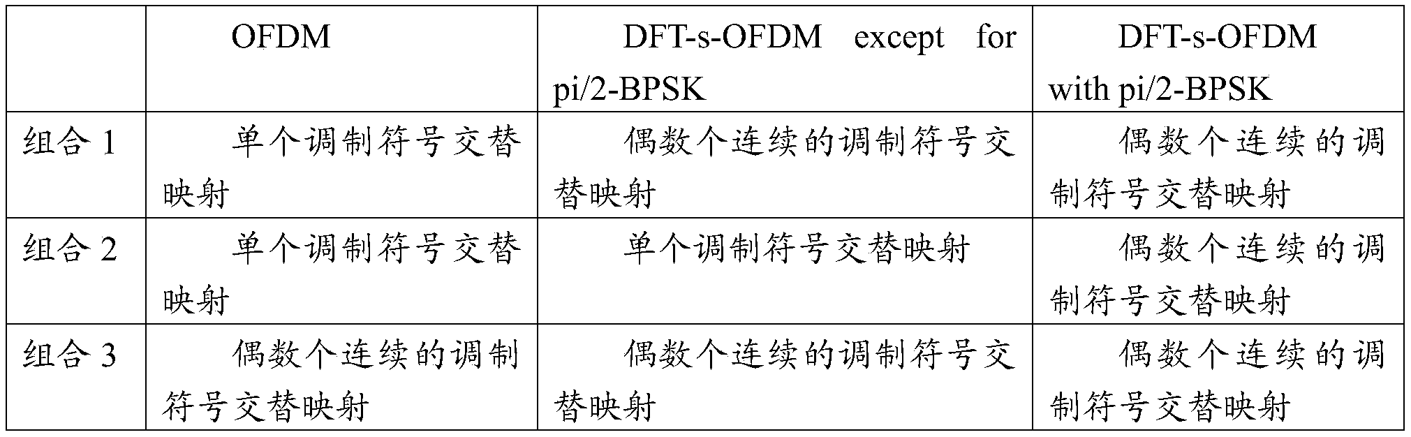

Claims (26)
- 一种分集通信的方法,其特征在于,所述方法包括:第一设备将多个调制符号映射至多个天线端口上;在每次映射中,将多个连续的调制符号映射至一个天线端口;所述多个调制符号基于一个传输块生成;所述第一设备对每个天线端口上的调制符号进行以下处理:将多个调制符号映射至频域资源上,所述频域资源为天线端口对应的频域资源;其中,不同的天线端口对应的频域资源的不重叠。
- 如权利要求1所述的方法,其特征在于,在每次映射中,将偶数个连续的调制符号映射至一个天线端口。
- 一种分集通信的方法,其特征在于,所述方法包括:第一设备对一个传输块进行处理,生成多个码字;所述第一设备对每个码字分别进行以下处理:对码字中的比特进行调制,得到多个调制符号,并将所述多个调制符号映射至频域资源上,所述频域资源为天线端口对应的频域资源;其中,不同的码字对应不同的天线端口,不同的天线端口对应频域资源不重叠。
- 如权利要求3所述的方法,其特征在于,一个码字为所述传输块的一个冗余版本。
- 如权利要求1-4任一项所述的方法,其特征在于,每个天线端口对应的频域资源不连续;或者,每个天线端口对应的频域资源连续。
- 如权利要求5所述的方法,其特征在于,每个天线端口对应的频域资源不连续包括以下任一种:所述频域资源所包括的多个资源元素RE不连续;所述频域资源所包括的多个预编码资源块组PRG不连续;所述频域资源所包括的多个物理资源块PRB不连续。
- 如权利要求1-6任一项所述的方法,其特征在于,还包括:所述第一设备接收第一指示,所述第一指示用于指示将多个调制符号映射至频域资源的映射方式。
- 如权利要求1-7任一项所述的方法,其特征在于,还包括:所述第一设备接收一个或多个解调参考信号DMRS端口标识。
- 如权利要求8所述的方法,其特征在于,在接收到多个DMRS端口标识的情况下,所述频域资源包括多个不连续的资源元素RE;或者,在接收到一个DMRS端口标识的情况下,每个天线端口对应的频域资源连续;或者,所述频域资源包括多个不连续的预编码资源块组PRG;或者,所述频域资源包括多个不连续的物理资源块PRB。
- 如权利要求1-9任一项所述的方法,其特征在于,还包括:所述第一设备接收一个或多个子带的信息,所述子带的信息用于确定天线端口对应的频域资源。
- 如权利要求10所述的方法,其特征在于,在接收到子带的信息的情况下,每个天线端口对应的频域资源连续。
- 一种分集通信的装置,其特征在于,所述装置包括:处理模块,用于将多个调制符号映射至多个天线端口上;在每次映射中,将多个连续的调制符号映射至一个天线端口;所述多个调制符号基于一个传输块生成;对每个天线端口上的调制符号进行以下处理:将多个调制符号映射至频域资源上,所述频域资源为天线端口对应的频域资源;其中,不同的天线端口对应的频域资源的不重叠;收发模块,用于发送映射到各个天线端口对应的频域资源上的调制符号。
- 如权利要求12所述的装置,其特征在于,在每次映射中,将偶数个连续的调制符号映射至一个天线端口。
- 一种分集通信的装置,其特征在于,所述装置包括:处理模块,用于对一个传输块进行处理,生成多个码字;以及对每个码字分别进行以下处理:对码字中的比特进行调制,得到多个调制符号,并将所述多个调制符号映射至频域资源上,所述频域资源为天线端口对应的频域资源;其中,不同的码字对应不同的天线端口,不同的天线端口对应频域资源不重叠;收发模块,用于发送映射到各个天线端口对应的频域资源上的调制符号。
- 如权利要求14所述的装置,其特征在于,一个码字为所述传输块的一个冗余版本。
- 如权利要求12-15任一项所述的装置,其特征在于,每个天线端口对应的频域资源不连续;或者,每个天线端口对应的频域资源连续。
- 如权利要求16所述的装置,其特征在于,当每个天线端口对应的频域资源不连续时,包括以下任一种:所述频域资源所包括的多个资源元素RE不连续;所述频域资源所包括的多个预编码资源块组PRG不连续;所述频域资源所包括的多个物理资源块PRB不连续。
- 如权利要求12-17任一项所述的装置,其特征在于,所述收发模块,还用于接收第一指示,所述第一指示用于指示将多个调制符号映射至频域资源的映射方式。
- 如权利要求12-18任一项所述的装置,其特征在于,所述收发模块,还用于接收一个或多个解调参考信号DMRS端口标识。
- 如权利要求19所述的装置,其特征在于,在接收到多个DMRS端口标识的情况下,所述频域资源包括多个不连续的资源元素RE;或者,在接收到一个DMRS端口标识的情况下,每个天线端口对应的频域资源连续;或者,所述频域资源包括多个不连续的预编码资源块组PRG;或者,所述频域资源包括多个不连续的物理资源块PRB。
- 如权利要求12-20任一项所述的装置,其特征在于,所述收发模块,还用于接收一个或多个子带的信息,所述子带的信息用于确定天线端口对应的频域资源。
- 如权利要求21所述的装置,其特征在于,在接收到子带的信息的情况下,每个天线端口对应的频域资源连续。
- 一种通信装置,其特征在于,包括处理器和存储器;所述存储器,用于存储计算机程序指令;所述处理器,用于执行所述存储器中的部分或者全部计算机程序指令,当所述部分或 者全部计算机程序指令被执行时,用于实现如权利要求1-11任一项所述的方法。
- 一种芯片系统,其特征在于,所述芯片系统包括:处理电路;所述处理电路与存储介质耦合;所述处理电路,用于执行所述存储介质中的部分或者全部计算机程序指令,当所述部分或者全部计算机程序指令被执行时,用于实现如权利要求1-11任一项所述的方法。
- 一种计算机可读存储介质,其特征在于,用于存储计算机程序,所述计算机程序包括用于实现权利要求1-11任一项所述的方法的指令。
- 一种计算机程序产品,其特征在于,所述计算机程序产品包括:计算机程序代码,当所述计算机程序代码在计算机上运行时,使得计算机执行如权利要求1-11任一项所述的方法。
Priority Applications (6)
| Application Number | Priority Date | Filing Date | Title |
|---|---|---|---|
| CN202510370739.XA CN120434094A (zh) | 2020-09-30 | 2020-09-30 | 一种分集通信的方法及装置 |
| EP20955772.7A EP4210237B1 (en) | 2020-09-30 | 2020-09-30 | Diversity communication method and apparatus |
| CN202080105109.5A CN116114227B (zh) | 2020-09-30 | 2020-09-30 | 一种分集通信的方法及装置 |
| PCT/CN2020/119632 WO2022067749A1 (zh) | 2020-09-30 | 2020-09-30 | 一种分集通信的方法及装置 |
| CA3194470A CA3194470A1 (en) | 2020-09-30 | 2020-09-30 | Diversity communication method and apparatus |
| US18/192,164 US12489494B2 (en) | 2020-09-30 | 2023-03-29 | Diversity communication method and apparatus |
Applications Claiming Priority (1)
| Application Number | Priority Date | Filing Date | Title |
|---|---|---|---|
| PCT/CN2020/119632 WO2022067749A1 (zh) | 2020-09-30 | 2020-09-30 | 一种分集通信的方法及装置 |
Related Child Applications (1)
| Application Number | Title | Priority Date | Filing Date |
|---|---|---|---|
| US18/192,164 Continuation US12489494B2 (en) | 2020-09-30 | 2023-03-29 | Diversity communication method and apparatus |
Publications (1)
| Publication Number | Publication Date |
|---|---|
| WO2022067749A1 true WO2022067749A1 (zh) | 2022-04-07 |
Family
ID=80951156
Family Applications (1)
| Application Number | Title | Priority Date | Filing Date |
|---|---|---|---|
| PCT/CN2020/119632 Ceased WO2022067749A1 (zh) | 2020-09-30 | 2020-09-30 | 一种分集通信的方法及装置 |
Country Status (5)
| Country | Link |
|---|---|
| US (1) | US12489494B2 (zh) |
| EP (1) | EP4210237B1 (zh) |
| CN (2) | CN120434094A (zh) |
| CA (1) | CA3194470A1 (zh) |
| WO (1) | WO2022067749A1 (zh) |
Cited By (3)
| Publication number | Priority date | Publication date | Assignee | Title |
|---|---|---|---|---|
| US20210400729A1 (en) * | 2019-03-07 | 2021-12-23 | Shanghai Langbo Communication Technology Company Limited | Method and device in node used for wireless communication |
| WO2024119487A1 (zh) * | 2022-12-09 | 2024-06-13 | 华为技术有限公司 | 电调设备的管理方法与通信装置 |
| WO2024234350A1 (zh) * | 2023-05-17 | 2024-11-21 | 北京小米移动软件有限公司 | 一种通信方法、装置及存储介质 |
Families Citing this family (2)
| Publication number | Priority date | Publication date | Assignee | Title |
|---|---|---|---|---|
| CN115883306A (zh) * | 2021-09-29 | 2023-03-31 | 中兴通讯股份有限公司 | 数据传输方法、数据调制方法、电子设备和存储介质 |
| CN119071129A (zh) * | 2023-05-30 | 2024-12-03 | 华为技术有限公司 | 符号处理的方法、装置以及系统 |
Citations (8)
| Publication number | Priority date | Publication date | Assignee | Title |
|---|---|---|---|---|
| CN101431357A (zh) * | 2007-11-08 | 2009-05-13 | 大唐移动通信设备有限公司 | 一种数据传输的方法和装置 |
| US20110176632A1 (en) * | 2010-01-20 | 2011-07-21 | Electronics And Telecommunications Research Institute | Method of transmitting uplink dm-rs multiplexed with data in uplink mimo transmission |
| US20120076158A1 (en) * | 2009-03-10 | 2012-03-29 | Samsung Electronics Co., Ltd. | Method and apparatus for transmitting/receiving data in single carrier frequency division multiple access system |
| CN105656608A (zh) * | 2014-11-13 | 2016-06-08 | 中国移动通信集团公司 | 一种导频资源分配方法、装置和基站 |
| US9596017B1 (en) * | 2009-10-19 | 2017-03-14 | Marvell International Ltd. | Transmission-mode-aware rate matching in MIMO signal generation |
| CN107733617A (zh) * | 2016-08-12 | 2018-02-23 | 华为技术有限公司 | 参考信号映射方法及装置 |
| CN109716690A (zh) * | 2016-09-19 | 2019-05-03 | 高通股份有限公司 | 每符号k比特交织器 |
| CN110915286A (zh) * | 2018-01-11 | 2020-03-24 | Lg电子株式会社 | 在无线通信系统中操作终端的方法和使用该方法的装置 |
Family Cites Families (9)
| Publication number | Priority date | Publication date | Assignee | Title |
|---|---|---|---|---|
| KR20110081946A (ko) * | 2008-08-11 | 2011-07-15 | 엘지전자 주식회사 | 다중 안테나 시스템에서 다중 부호어의 전송방법 |
| WO2010041868A2 (ko) * | 2008-10-08 | 2010-04-15 | 엘지전자주식회사 | 다중 안테나 시스템에서 데이터 전송 방법 및 장치 |
| KR101646259B1 (ko) * | 2009-02-16 | 2016-08-08 | 엘지전자 주식회사 | 다중 안테나 시스템에서 데이터의 전송방법 |
| WO2013022260A2 (ko) * | 2011-08-07 | 2013-02-14 | 엘지전자 주식회사 | 상향링크 제어정보 전송방법 및 사용자기기 |
| KR102608632B1 (ko) * | 2016-11-23 | 2023-12-01 | 삼성전자 주식회사 | 셀룰라 통신 시스템에서 상향링크 전송 방법 및 장치 |
| JP2019092062A (ja) * | 2017-11-15 | 2019-06-13 | シャープ株式会社 | 端末装置、基地局装置、および、通信方法 |
| CN114866211A (zh) * | 2018-10-12 | 2022-08-05 | 华为技术有限公司 | 数据传输方法和通信装置 |
| US11902971B2 (en) * | 2018-12-21 | 2024-02-13 | Lg Electronics Inc. | Method for operating terminal and base station in wireless communication system, and device supporting same |
| CN111436129B (zh) * | 2019-01-11 | 2023-10-24 | 华为技术有限公司 | 数据传输方法和通信装置 |
-
2020
- 2020-09-30 CA CA3194470A patent/CA3194470A1/en active Pending
- 2020-09-30 WO PCT/CN2020/119632 patent/WO2022067749A1/zh not_active Ceased
- 2020-09-30 EP EP20955772.7A patent/EP4210237B1/en active Active
- 2020-09-30 CN CN202510370739.XA patent/CN120434094A/zh active Pending
- 2020-09-30 CN CN202080105109.5A patent/CN116114227B/zh active Active
-
2023
- 2023-03-29 US US18/192,164 patent/US12489494B2/en active Active
Patent Citations (8)
| Publication number | Priority date | Publication date | Assignee | Title |
|---|---|---|---|---|
| CN101431357A (zh) * | 2007-11-08 | 2009-05-13 | 大唐移动通信设备有限公司 | 一种数据传输的方法和装置 |
| US20120076158A1 (en) * | 2009-03-10 | 2012-03-29 | Samsung Electronics Co., Ltd. | Method and apparatus for transmitting/receiving data in single carrier frequency division multiple access system |
| US9596017B1 (en) * | 2009-10-19 | 2017-03-14 | Marvell International Ltd. | Transmission-mode-aware rate matching in MIMO signal generation |
| US20110176632A1 (en) * | 2010-01-20 | 2011-07-21 | Electronics And Telecommunications Research Institute | Method of transmitting uplink dm-rs multiplexed with data in uplink mimo transmission |
| CN105656608A (zh) * | 2014-11-13 | 2016-06-08 | 中国移动通信集团公司 | 一种导频资源分配方法、装置和基站 |
| CN107733617A (zh) * | 2016-08-12 | 2018-02-23 | 华为技术有限公司 | 参考信号映射方法及装置 |
| CN109716690A (zh) * | 2016-09-19 | 2019-05-03 | 高通股份有限公司 | 每符号k比特交织器 |
| CN110915286A (zh) * | 2018-01-11 | 2020-03-24 | Lg电子株式会社 | 在无线通信系统中操作终端的方法和使用该方法的装置 |
Non-Patent Citations (2)
| Title |
|---|
| 3GPP PROTOCOL 36.211 |
| See also references of EP4210237A4 |
Cited By (4)
| Publication number | Priority date | Publication date | Assignee | Title |
|---|---|---|---|---|
| US20210400729A1 (en) * | 2019-03-07 | 2021-12-23 | Shanghai Langbo Communication Technology Company Limited | Method and device in node used for wireless communication |
| US12052759B2 (en) * | 2019-03-07 | 2024-07-30 | Shanghai Langbo Communication Technology Company Limited | Method and device in node used for wireless communication |
| WO2024119487A1 (zh) * | 2022-12-09 | 2024-06-13 | 华为技术有限公司 | 电调设备的管理方法与通信装置 |
| WO2024234350A1 (zh) * | 2023-05-17 | 2024-11-21 | 北京小米移动软件有限公司 | 一种通信方法、装置及存储介质 |
Also Published As
| Publication number | Publication date |
|---|---|
| CN116114227A8 (zh) | 2024-05-28 |
| US20230246677A1 (en) | 2023-08-03 |
| US12489494B2 (en) | 2025-12-02 |
| CN116114227B (zh) | 2025-12-02 |
| EP4210237A4 (en) | 2023-10-25 |
| CN120434094A (zh) | 2025-08-05 |
| EP4210237A1 (en) | 2023-07-12 |
| EP4210237B1 (en) | 2025-06-25 |
| CA3194470A1 (en) | 2022-04-07 |
| CN116114227A (zh) | 2023-05-12 |
Similar Documents
| Publication | Publication Date | Title |
|---|---|---|
| US10973020B2 (en) | Signal scrambling method and apparatus, and signal descrambling method and apparatus | |
| US11563526B2 (en) | Apparatus and method for performing retransmission in wireless communication system | |
| CN109274472B (zh) | 数据传输方法、网络设备和终端设备 | |
| CN113556818B (zh) | 用于执行通信的方法和基站 | |
| CN107534541B (zh) | 用于在无线通信系统中发送参考信号的装置和方法 | |
| US20230261841A1 (en) | Signal transmission method and apparatus | |
| JP7766078B2 (ja) | 制御情報送受信のための装置及び方法 | |
| WO2019137057A1 (zh) | 资源指示方法、终端设备和网络设备 | |
| CN116114227B (zh) | 一种分集通信的方法及装置 | |
| JP2019149827A (ja) | 5個を超えるセルをキャリアアグリゲーションによって使用する時のpucch送信方法及びユーザ装置 | |
| CN108632193B (zh) | 一种资源指示方法及网络设备、终端设备 | |
| CN116321488B (zh) | 通信方法以及通信装置 | |
| WO2018116817A1 (ja) | 基地局装置、端末装置、通信方法、および、集積回路 | |
| US20210136805A1 (en) | Method and apparatus for scheduling and transmitting data in wireless cellular communication system | |
| CN118435538A (zh) | 并行上行链路传输 | |
| CN117044357A (zh) | 用于在无线通信系统中发送下行链路数据作为重复的下行链路控制信息的方法和设备 | |
| WO2022077373A1 (zh) | 一种传输信号的方法及装置 | |
| WO2021238635A1 (zh) | 一种通信方法及装置 | |
| EP3840281A1 (en) | Communication method and apparatus | |
| WO2022205022A1 (zh) | 用于传输参考信号的方法和装置 | |
| WO2018116806A1 (ja) | 基地局装置、端末装置、通信方法、および、集積回路 | |
| CN119096639A (zh) | 用于多天线面板物理上行链路控制信道发送的控制信令 | |
| EP4482096A1 (en) | Transmission of faster than nyquist signaling | |
| WO2018082365A1 (zh) | 传输控制方法、装置及系统存储介质 | |
| WO2024067305A1 (zh) | 单载波通信方法和通信装置 |
Legal Events
| Date | Code | Title | Description |
|---|---|---|---|
| 121 | Ep: the epo has been informed by wipo that ep was designated in this application |
Ref document number: 20955772 Country of ref document: EP Kind code of ref document: A1 |
|
| WWE | Wipo information: entry into national phase |
Ref document number: 202080105109.5 Country of ref document: CN |
|
| ENP | Entry into the national phase |
Ref document number: 3194470 Country of ref document: CA |
|
| ENP | Entry into the national phase |
Ref document number: 2020955772 Country of ref document: EP Effective date: 20230404 |
|
| NENP | Non-entry into the national phase |
Ref country code: DE |
|
| WWG | Wipo information: grant in national office |
Ref document number: 2020955772 Country of ref document: EP |