WO2022068714A1 - 传输配置的方法、装置和设备 - Google Patents
传输配置的方法、装置和设备 Download PDFInfo
- Publication number
- WO2022068714A1 WO2022068714A1 PCT/CN2021/120613 CN2021120613W WO2022068714A1 WO 2022068714 A1 WO2022068714 A1 WO 2022068714A1 CN 2021120613 W CN2021120613 W CN 2021120613W WO 2022068714 A1 WO2022068714 A1 WO 2022068714A1
- Authority
- WO
- WIPO (PCT)
- Prior art keywords
- terminal device
- bearer
- access network
- related information
- terminal
- Prior art date
- Legal status (The legal status is an assumption and is not a legal conclusion. Google has not performed a legal analysis and makes no representation as to the accuracy of the status listed.)
- Ceased
Links
Images




Classifications
-
- H—ELECTRICITY
- H04—ELECTRIC COMMUNICATION TECHNIQUE
- H04W—WIRELESS COMMUNICATION NETWORKS
- H04W48/00—Access restriction; Network selection; Access point selection
- H04W48/18—Selecting a network or a communication service
-
- H—ELECTRICITY
- H04—ELECTRIC COMMUNICATION TECHNIQUE
- H04W—WIRELESS COMMUNICATION NETWORKS
- H04W76/00—Connection management
- H04W76/20—Manipulation of established connections
- H04W76/27—Transitions between radio resource control [RRC] states
-
- H—ELECTRICITY
- H04—ELECTRIC COMMUNICATION TECHNIQUE
- H04W—WIRELESS COMMUNICATION NETWORKS
- H04W36/00—Hand-off or reselection arrangements
- H04W36/0005—Control or signalling for completing the hand-off
- H04W36/0009—Control or signalling for completing the hand-off for a plurality of users or terminals, e.g. group communication or moving wireless networks
-
- H—ELECTRICITY
- H04—ELECTRIC COMMUNICATION TECHNIQUE
- H04W—WIRELESS COMMUNICATION NETWORKS
- H04W76/00—Connection management
- H04W76/10—Connection setup
- H04W76/14—Direct-mode setup
-
- H—ELECTRICITY
- H04—ELECTRIC COMMUNICATION TECHNIQUE
- H04W—WIRELESS COMMUNICATION NETWORKS
- H04W76/00—Connection management
- H04W76/10—Connection setup
- H04W76/15—Setup of multiple wireless link connections
-
- H—ELECTRICITY
- H04—ELECTRIC COMMUNICATION TECHNIQUE
- H04W—WIRELESS COMMUNICATION NETWORKS
- H04W8/00—Network data management
- H04W8/22—Processing or transfer of terminal data, e.g. status or physical capabilities
-
- H—ELECTRICITY
- H04—ELECTRIC COMMUNICATION TECHNIQUE
- H04W—WIRELESS COMMUNICATION NETWORKS
- H04W80/00—Wireless network protocols or protocol adaptations to wireless operation
- H04W80/02—Data link layer protocols
-
- H—ELECTRICITY
- H04—ELECTRIC COMMUNICATION TECHNIQUE
- H04W—WIRELESS COMMUNICATION NETWORKS
- H04W88/00—Devices specially adapted for wireless communication networks, e.g. terminals, base stations or access point devices
- H04W88/02—Terminal devices
- H04W88/04—Terminal devices adapted for relaying to or from another terminal or user
-
- H—ELECTRICITY
- H04—ELECTRIC COMMUNICATION TECHNIQUE
- H04W—WIRELESS COMMUNICATION NETWORKS
- H04W92/00—Interfaces specially adapted for wireless communication networks
- H04W92/16—Interfaces between hierarchically similar devices
- H04W92/18—Interfaces between hierarchically similar devices between terminal devices
Definitions
- the present application relates to the field of communications, and in particular, to a method, apparatus and device for transmitting configuration.
- a Long Term Evolution (Long Term Evolution, LTE) system supports sidelink (Sidelink, SL, which may also be referred to as a side link, a secondary link, or a side link, etc.) transmission.
- SL is used for direct data transmission between user equipment (User Equipment, UE, which may also be called terminal equipment, user terminal, mobile terminal, etc.) without using network equipment, as shown in FIG. 1 .
- User Equipment User Equipment
- Embodiments of the present application provide a method, apparatus, and device for transmission configuration, so as to be able to solve the problem of how to implement continuous transmission of a common service data between multiple UEs.
- a first aspect provides a method for transmitting a configuration, the method comprising: a first access network device sending bearer-related information to a first terminal device, where the bearer-related information is used to instruct the first terminal device Perform cooperative transmission with the second terminal device.
- an apparatus for transmitting configuration is provided, which is applied to a first access network device.
- the apparatus includes: a sending module configured to send bearer-related information to the first terminal device, where the bearer-related information is used for for instructing the first terminal device and the second terminal device to perform cooperative transmission.
- a network-side device including: a memory, a processor, and a program or instruction stored on the memory and executable on the processor, where the program or instruction is executed by the processor When implementing the method for transmitting a configuration according to the first aspect.
- a method for transmitting configuration comprising: receiving, by a first terminal device, bearer-related information configured by a first access network device; and, according to the bearer-related information, the first terminal device and The second terminal device performs cooperative transmission.
- an apparatus for transmitting configuration applied to a first terminal device, the apparatus includes: a receiving module configured to receive bearer-related information configured by the first access network device; The bearer-related information is cooperatively transmitted with the second terminal device.
- a terminal device comprising: a memory, a processor, and a program or instruction stored on the memory and executable on the processor, when the program or instruction is executed by the processor.
- a readable storage medium on which a program or an instruction is stored, and when the program or instruction is executed by a processor, the steps of the method for transmitting a configuration as described in the first aspect are implemented, Or, when the program or instructions are executed by the processor, the steps of the method for transmitting a configuration according to the fourth aspect are implemented.
- a computer program product is provided, the computer program product is stored in a non-volatile readable storage medium, and when the computer program product is executed by a processor, the method for transmitting a configuration according to the first aspect is implemented or the steps of implementing the method for transmitting a configuration according to the fourth aspect when the program or instructions are executed by the processor.
- a chip in a ninth aspect, includes a processor and a communication interface, the communication interface is coupled to the processor, and the processor is used to run a terminal device or a network side device program or instruction, to achieve the The steps of the method for transmitting a configuration described in one aspect, or the steps of implementing the method for transmitting a configuration as described in the fourth aspect.
- the first access network device configures corresponding bearer-related information for each terminal device among the multiple terminal devices.
- the terminal device configures the corresponding bearer-related information, so that the first terminal device can perform cooperative transmission with a second terminal device according to the bearer-related information, wherein the second terminal device includes at least one terminal device other than the first terminal device.
- Terminal Equipment In this way, by configuring bearer-related information, at least two terminal devices can perform cooperative transmission, thereby realizing continuous transmission between the at least two terminal devices, and ensuring service experience and system efficiency of the terminal devices.
- FIG. 1 is a schematic diagram of a communication scenario including a side link in an embodiment of the present application
- FIG. 2 shows a block diagram of a wireless communication system to which an embodiment of the present application can be applied
- FIG. 3 is a schematic flowchart of a method for transmitting configuration in an embodiment of the present application.
- FIG. 4 is a schematic diagram of a bearer aggregated by multiple terminal devices in an embodiment of the present application.
- FIG. 5 is a schematic diagram of a mapping relationship between bearers in an embodiment of the present application.
- FIG. 6 is a schematic flowchart of another method for transmitting configuration in an embodiment of the present application.
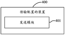
- FIG. 7 is a schematic structural diagram of an apparatus for transmitting configuration in an embodiment of the present application.
- FIG. 8 is a schematic structural diagram of an apparatus for another transmission configuration in an embodiment of the present application.
- FIG. 9 is a schematic structural diagram of a communication device in an embodiment of the present application.
- FIG. 10 is a schematic structural diagram of a terminal device in an embodiment of the present application.
- FIG. 11 is a schematic structural diagram of a network side device in an embodiment of the present application.
- first, second and the like in the description and claims of the present application are used to distinguish similar objects, and are not used to describe a specific order or sequence. It is to be understood that the data so used are interchangeable under appropriate circumstances so that the embodiments of the present application can be practiced in sequences other than those illustrated or described herein, and "first”, “second” distinguishes Usually it is a class, and the number of objects is not limited.
- the first object may be one or multiple.
- “and/or” in the description and claims indicates at least one of the connected objects, and the character “/" generally indicates that the associated objects are in an "or” relationship.
- LTE Long Term Evolution
- LTE-Advanced LTE-Advanced
- LTE-A Long Term Evolution-Advanced
- CDMA Code Division Multiple Access
- TDMA Time Division Multiple Access
- FDMA Frequency Division Multiple Access
- OFDMA Orthogonal Frequency Division Multiple Access
- SC-FDMA Single-carrier Frequency-Division Multiple Access
- system and “network” in the embodiments of the present application are often used interchangeably, and the described technology can be used not only for the above-mentioned systems and radio technologies, but also for other systems and radio technologies.
- NR New Radio
- the following description describes a New Radio (NR) system for example purposes, and uses NR terminology in most of the following description, these techniques are also applicable to applications other than NR system applications, such as 6th generation (6 th Generation, 6G) communication system.
- 6th generation 6 th Generation, 6G
- FIG. 2 shows a block diagram of a wireless communication system to which the embodiments of the present application can be applied.
- the wireless communication system includes a terminal 11 and a network-side device 12 .
- the terminal 11 may also be called a terminal device or a user terminal (User Equipment, UE), and the terminal 11 may be a mobile phone, a tablet computer (Tablet Personal Computer), a laptop computer (Laptop Computer) or a notebook computer, a personal digital computer Assistant (Personal Digital Assistant, PDA), handheld computer, netbook, ultra-mobile personal computer (ultra-mobile personal computer, UMPC), mobile Internet device (Mobile Internet Device, MID), wearable device (Wearable Device) or vehicle-mounted device (Vehicle UE, VUE), pedestrian terminal (Pedestrian UE, PUE) and other terminal-side devices, wearable devices include: bracelets, headphones, glasses, etc.
- the network side device 12 may be a base station or a core network, wherein the base station may be referred to as a Node B, an evolved Node B, an access point, a Base Transceiver Station (BTS), a radio base station, a radio transceiver, a basic service Set (Basic Service Set, BSS), Extended Service Set (Extended Service Set, ESS), Node B, Evolved Node B (eNB), Home Node B, Home Evolved Node B, WLAN Access Point, WiFi Node, Send Transmitting Receiving Point (TRP) or some other suitable term in the field, as long as the same technical effect is achieved, the base station is not limited to specific technical terms.
- the base station in the NR system is taken as an example, but the specific type of the base station is not limited.
- an embodiment of the present application provides a method for transmitting configuration, and the method includes the following process steps.
- Step 201 The first access network device sends bearer-related information to the first terminal device, where the bearer-related information is used to instruct the first terminal device to perform cooperative transmission with the second terminal device.
- the first access network device configures corresponding bearer-related information for each terminal device among the multiple terminal devices.
- the terminal device configures the corresponding bearer-related information, so that the first terminal device can perform cooperative transmission with a second terminal device according to the bearer-related information, wherein the second terminal device includes at least one terminal device other than the first terminal device.
- Terminal Equipment In this way, by configuring bearer-related information, at least two terminal devices can perform cooperative transmission, thereby realizing continuous transmission between the at least two terminal devices, and ensuring service experience and system efficiency of the terminal devices.
- the cooperative transmission between the above-mentioned at least two terminal devices may also be understood as aggregated transmission or dual connectivity (Dual connectivity, DC) transmission.
- the first access network device may configure a bearer for the first terminal device through the bearer-related information, so that the first terminal device and the second terminal device can perform communication between the first terminal device and the second terminal device.
- Bearer aggregation to ensure cooperative transmission.
- the above bearer-related information includes one of the following.
- the first access network device only configures the PDCP bearer for the first terminal device, at this time, the first access network device is configured with a PDCP bearer.
- the network device configures radio link control (Radio Link Control, RLC bearer) for the second terminal device, that is, the PDCP bearer and the RLC bearer are located in different terminal devices.
- RLC bearer Radio Link Control
- this type of bearer can be recorded as UE1-UE2bearer, where UE1 represents a PDCP bearer in UE1, such as UE1PDCP bearer n1, and UE2 represents an RLC bearer in UE2, such as UE2RLC bearer m1.
- Radio Link Control (Radio Link Control, RLC) bearer in this embodiment, the first access network device is only configured with an RLC bearer for the first terminal device, and at this time, the first access network device may be
- the second terminal device configures the PDCP bearer, that is, the PDCP bearer and the RLC bearer are located in different terminal devices.
- this type of bearer can be denoted as UE2-UE1bearer, where UE2 represents the PDCP bearer in UE2, and UE1 represents the RLC bearer in UE1.
- this type of bearer can also be recorded as a split bearer, that is, UE2 split bearer, PDCP bearer is located in UE2, and at least one RLC bearer is located in other terminal equipment except UE2, for example, there is an RLC bearer
- the bearer is located in UE1, for example, there are two RLC bearers located in UE1 and UE3.
- the first access network device configures PDCP bearer and RLC bearer for the first terminal device, and at this time, the first access network device may configure the second terminal device
- the RLC bearer that is, the PDCP bearer is located in one terminal device of multiple terminal devices, and the corresponding RLC bearer is located in at least two terminal devices of the multiple terminal devices respectively.
- this type of bearer can be recorded as splitbearer, that is, the PDCP bearer is located in UE1, and the RLC bearer can be located in two or more terminal devices, such as UE1 and UE2, at this time, PDCP bearer n1 and RLC bearer n2 is located in UE1, and RLC bearer m1 is located in UE2.
- the above PDCP bearer mainly refers to the part composed of PDCP and above entities corresponding to a dedicated wireless bearer, mainly including PDCPsublayer and SDAPsublayer, because the PDCP layer is an important protocol layer that provides functions such as reordering and security, so the PDCP layer Attribution determines how the security parameters are used and where the reordering function is located, and is an important protocol layer for providing business continuity and security.
- the RLC layer and the following protocol layers mainly provide air interface transmission.
- PDCP bearer can be recorded as including PDCP and Service Data Adaptation Protocol (Service Data Adaptation Protocol, SDAP) two-layer protocol stack, RLC bearer includes RLC, medium access control (Medium Access Control, MAC) and physical layer (Physical layer) , PHY) three layers.
- SDAP Service Data Adaptation Protocol
- RLC bearer includes RLC, medium access control (Medium Access Control, MAC) and physical layer (Physical layer) , PHY) three layers.
- the splitbearer is a typical PDCP bearer located in UE1, and the two RLC bearers are located in the UE1 splitbearer of UE1 and UE2 respectively. Due to the split bearing, it can be transmitted through multiple legs (RLC bearer), and it can be divided into the following two transmission methods.
- Split transmission It means that a data packet can only be transmitted by one path, either RLC bearer 1 or RLC bearer 2.
- the specific selection mechanism can be configured by network-side devices (such as base stations).
- Duplication transmission refers to the duplication transmission of a data packet on two or more paths at the same time, that is, duplication transmission is performed in RLC bearer 1 and RLC bearer 2 at the same time, and the duplication transmission can be performed by network-side devices (such as base stations) ) configuration.
- RLC bearers can be transmitted in split mode or in duplication mode.
- SDU RLC Service Data Unit
- entity entity
- duplicate data is deleted and deleted. Arranged in order and then submitted to the high-level.
- the first access network device may configure a service/Quality of Service (Quality of Service, QoS) flow (flow)/data wireless
- the bearer Data Radio Bearer, DRB
- DRB Data Radio Bearer
- the PDCP bearer is configured in one of the UEs, such as UE1 or UE2; or the service/QoSflow/DRB is configured to be replicated and transmitted in UE1 and UE2 at the same time; or PDCP bearer and RLC bearer are located in UE1 and UE2, respectively.
- the bearer-related information may include: RLC bearers corresponding to PC5 interfaces of the first terminal device and the second terminal device. That is to say, when cooperative transmission is performed between multiple terminal devices, the terminal devices can be transmitted through the interface between the terminal devices, such as the PC5 interface of the direct connection interface or the sidelink interface of the secondary link, and the PC5RLC bearer is configured.
- the information related to the bearer may further include at least one of the following: the RLC bearer corresponding to the PC5 interface of the first terminal device and the Uu interface (cellular communication).
- the RLC bearer corresponding to the PC5 interface of each terminal device can be in one-to-one correspondence with the corresponding UuPDCP entity that needs to be forwarded between terminal devices.
- it can be configured through PC5RRC.
- the UE1PDCP bearer is shunted to: UE1RLC bearer and UE1-UE2PC5RLC bearer (->UE2RLC bearer), which is equivalent to two optional paths.
- the first terminal device satisfies at least one of the following.
- Pre-set contract conditions for example, shared packages, common charges, or bound users, etc.
- the second terminal device has the same setting or state requirements for the same terminal application; for example, two devices of the user are set with a continuous reception requirement for a certain common service or application (Application, APP).
- Preset communication conditions with the second terminal device That is to say, considering whether it is UE1splitbearer or UE1-UE2bearer, these two bearer types have the characteristics that PDCP bearer and RLC bearer are located in different UEs, and RLCSDU is to converge to PDCPentity and needs to be used between UE-UE At this time, two UEs are close to each other, and the configuration of this special bearer is only performed when the UE-UE communication conditions are met.
- the method may further include the following content: the first access network device receives a first request; wherein the first access network device receives a first request; At least one of the following must be included in the request.
- the identifier of the second terminal device for example, UE1 carries the identifier of UE2 in its dedicated RRC signaling, and this identifier may be a permanent identifier or a temporary identifier.
- the link quality between the first terminal device and the second terminal device such as PC5 reference signal received power (Reference Signal Received Power, RSRP).
- PC5 reference signal received power Reference Signal Received Power
- the step of receiving the first request by the above-mentioned first access network device may be performed as one of the following specific embodiments.
- the first access network device receives the first request sent by the core network device.
- the request of the UE1 may first reach the core network through a non-access stratum (NAS) process, and the core network will perform permission verification, and after the verification is passed, the base station will be notified for configuration execution.
- NAS non-access stratum
- the first terminal device UE1 initiates a service request for cooperative transmission, and in the process of service initiation or the intermediate process of service continuation, a request for multi-device aggregation service transmission is proposed, and the request is reported to the network side, and the The core network verifies the requirement, such as whether this function is allowed in the subscription data. After the verification is passed, the core network notifies the base station that the two devices can be configured for bearer aggregation. At this time, the request of the UE1 may first reach the core network through the NAS process, and the core network will perform permission verification, and after the verification is passed, the base station will be notified for configuration execution.
- the first access network device receives the first request sent by the first terminal device, where the first request is carried in a dedicated signaling for Radio Resource Control (RRC). middle.
- RRC Radio Resource Control
- the request of UE1 can also reach the access network device (such as the base station) directly through its own RRC process, and the access network device performs verification to the core network, and after the verification is passed, the access network device performs the verification.
- Configuration, or bearer-related information is stored in the context information of the UE1, such as binding the UE or the permitted service type, etc., and the configuration is performed after the access network device verifies.
- the step of receiving the first request sent by the first terminal device by the first access network device may be specifically performed as follows:
- the first access network device receives the first request sent by the first terminal device under the condition that at least one of the following is satisfied: the first access network device supports configuring all the bearer-related information; the first condition configured by the first access network device; wherein, the first condition includes at least one of the following: a link between the first terminal device and the second terminal device When the quality is higher than the first quality threshold, the first terminal device and the second terminal device perform cooperative transmission of specific service data.
- a terminal device before a terminal device initiates the requirement of cooperative transmission, it needs to know whether its service network supports this function, and needs to meet the conditions of network configuration, for example, the link quality between two devices meets certain threshold requirements, such as PC5RSRP is higher than threshold 1, and/or only certain services are allowed for multi-device aggregation transmission, such as multimedia real-time services.
- certain threshold requirements such as PC5RSRP is higher than threshold 1
- certain services are allowed for multi-device aggregation transmission, such as multimedia real-time services.
- the access network device configures multiple terminal devices to perform cooperative transmission
- the two or more terminal devices perform transmission according to the configured bearer mode. It should be noted that if it is configured as splitbearer, the network side also needs to configure additional parameters related to the data routing of splitbearer, such as which RLC bearer is the main leg, and the default data is transmitted on the main leg.
- the auxiliary leg that is, the RLC bearer other than the other main legs
- the auxiliary leg can be selected for transmission; if it is configured as a duplicationbearer, it needs to be configured as a splitbearer first, that is, it needs to have two or The above RLC bearers correspond to the same PDCP bearer in different UEs.
- the split bearer can be further configured as a duplication function, that is, the transmission can be replicated in two or more RLC bearers.
- the initial state of the duplication can be configured at the same time: the configuration is Activation (duplication mode transmission can be performed after configuration is completed), or configuration is deactivated (additional activation signaling is required for duplication mode transmission after configuration is completed), whether to support duplication dynamic activation/deactivation; after the configuration is completed, the terminal device
- the cooperative transmission can be carried out according to the parameters of the network configuration and related dynamic control.
- the method for transmitting configuration in this embodiment of the present application may further include at least one of the following items.
- the first access network device sends first configuration signaling to the first terminal device, where the first configuration signaling is used to instruct to configure or reconfigure the bearer of the first terminal device.
- the network side device such as the base station
- the network side device only needs to reconfigure it, delete the original bearer, and reconfigure it.
- the network side device (such as the base station) configures the PDCP configuration and SDAP configuration to UE1, and defaults or specifies that the PDCP bearer uses the key and security parameters of UE1, if the bearer If there is an RLC bearer located in UE1, the network-side device (such as a base station) configures the RLC configuration and the corresponding MAC, and the PHY is configured to UE1; the reconfiguration signaling to UE1 can include the configuration of multiple aggregated bearers.
- the first access network device sends a message to the second terminal device the second configuration signaling, where the second configuration signaling is used to instruct to configure or reconfigure the bearer of the second terminal device.
- the serving network side device such as the base station
- the serving network side device such as the base station
- Reconfiguration signaling configure the required aggregate bearer, if the PDCP bearer of the bearer is located in UE2, the network side device (such as the base station) configures the PDCP configuration and SDAP configuration to UE2, and defaults or indicates that the PDCP bearer uses UE2's key and security parameter, if the bearer is located in UE2 with an RLC bearer, the network-side device (such as a base station) configures the RLC configuration and the corresponding MAC, and the PHY is configured to UE2; the reconfiguration signaling to UE2 can include the configuration of multiple aggregated bearers.
- the first access network device paging the second terminal device when the second terminal device does not enter the RRC connected state, and after the second terminal device enters the RRC connected state, Send third configuration signaling to the second terminal device, where the third configuration signaling is used to instruct to configure or reconfigure the bearer of the second terminal device.
- the network side device such as the base station
- the network side device can paging the UE to make it enter the RRC connection state, and then send a retransmission to the UE2.
- Configure signaling and configure the required aggregated bearer, and the configuration content is similar to the content of the corresponding part in the above (2).
- the second terminal device switches to the first access network device when the first terminal device and the second terminal device are covered by different access network devices. After entering the coverage of the network device, a fourth configuration signaling is sent to the second terminal device, where the fourth configuration signaling is used to instruct to configure or reconfigure the bearer of the second terminal device.
- UE2 if another UE2 is not under the coverage of the same network-side device (such as a base station), for example, UE2 has established an RRC connection with another network-side device (such as a base station), or paging After that, UE2 establishes an RRC connection to another network-side device (such as a base station), and there are the following processing methods: For the case of cross-network-side devices (such as base stations), the UE2 will first be handed over to the same network-side device (such as base station). ), and then perform unified control.
- the same network-side device such as a base station
- the first access network device when the first terminal device and the second terminal device are under the coverage of different access network devices, access the second access network corresponding to the second terminal device
- the device sends fifth configuration signaling, where the fifth configuration signaling is used to instruct the second access network device to configure or reconfigure the bearer of the second terminal device.
- UE2 if another UE2 is not under the coverage of the same network-side device (such as a base station), for example, UE2 has established an RRC connection with another network-side device (such as a base station), or after paging, UE2 sends Another network-side device (such as a base station) establishes an RRC connection, and there are the following processing methods: coordinated control of cross-network-side devices (such as base stations), that is, UE1's serving network-side device (such as base station) 1 sends the proposed configuration to UE2 serves a network-side device (such as a base station) 2, where the PDCP bearer is located on which network-side device (such as a base station), and which network-side device (such as a base station) determines the configuration parameters, and the RLC bearer configuration is also determined by the respective home network-side device (such as The base station) decides, for example, for an aggregate bearer whose PDCP bearer is located in UE1, the network side equipment (such
- the configuration of each layer of the RLC bearer on the UE2 side is decided by the network side device (such as the base station) 2, and sent to UE2, the two network side devices (such as the base station) also need to establish a PDCP PDU for this splitbearer
- the forwarding channel is convenient for RLC bearer data to reach PDCP bearer.
- security parameters such as keys and algorithms
- the selection of security parameters is interactively configured between the UE where the PDCP layer is located and its home network side equipment (such as a base station), and the network side equipment (such as a base station) is configured to the UE. .
- the method for transmitting configuration in this embodiment of the present application may further include the following content: the first access network device reconfigures the bearer-related information.
- the bearer may need to be reconfigured due to changes in requirements or circumstances.
- the step of reconfiguring the bearer-related information by the first access network device includes at least one of the following.
- the first access network device reconfigures the bearer-related information when the user answering mode corresponding to the first terminal device changes.
- the user's answering method has changed, for example, he used a mobile phone to answer before, and then switched to using a watch to answer, or vice versa.
- the first access network device reconfigures the bearer-related information when the link quality between the first terminal device and the second terminal device is higher than a second quality threshold.
- the link between two or more terminals since the link between two or more terminals has changed, for example, before the two devices were close to each other, the link between the devices met the communication requirements, and aggregated bearer transmission could be performed. Far away, it does not meet the requirements of inter-device communication, and cannot perform aggregated bearer transmission.
- the information related to the bearer of the foregoing reconfiguration is used to indicate at least one of the following.
- the first terminal device When the PDCP bearer changes, the first terminal device performs a first operation on the PDCP bearer, where the first operation includes at least one of reconstruction and security update; the first terminal device does not change the PDCP bearer In the case of PDCP data recovery, the first terminal device resets all state variables.
- the bearer reconfiguration, the corresponding protocol data unit (Protocol Data Unit, PDU) session (session) connection involves at least the following two.
- the path from the network side equipment (such as the base station) to the core network can remain existing, and there are two branches: (1) When the aggregated bearer When the PDCP bearer and the PDCP bearer of the non-aggregated bearer are located at different terminals, if reconfiguration occurs, because the PDCP bearer has changed, the PDCP needs to be rebuilt, security updated, etc., and in order to maintain the Acknowledged Mode (Acknowledged Mode, The lossless transmission of AM) data requires the SN status transfer and data forwarding of the AMPDCP entity between the PDCP source anchorUE and the PDCP target anchorUE to keep the data transmission truly lossless.
- Unacknowledged Mode (Unacknowledged Mode, UM) data
- the PDCPSN state can be cleared from the initial value, and data forwarding can be optionally performed.
- the PDCP bearer of the aggregated bearer and the PDCP bearer of the non-aggregated bearer are located at the same terminal, reconfiguration occurs. Since the PDCP bearer does not change, operations such as PDCP reconstruction and security update are not required at this time. In the PDCP datarecovery process, data in different paths can be recovered.
- the other is the situation where the core network connection corresponding to the bearer needs to be switched.
- This situation refers to the situation where the core network connection changes before and after the aggregated bearer is configured, or after the aggregated bearer configuration and cancellation of the aggregated bearer configuration, such as UE1 initiates a service connection, uses its own PDU session, and then reconfigures it as a multi-device aggregated bearer, still maintaining the PDU session of UE1, and then configures it as only UE2bearer because the conditions of the aggregated bearer are not satisfied.
- the base station) to the core network needs to use the PDUsession of UE2, and the PDUsession is replaced; there are also two processing methods: (1) Since the core network path has changed, no matter whether the PDCP bearer changes, all state variables can be cleared (including AM and UM), starting from the initialization, the data transmission and reception in the new entity is repeated, the problem is that the AM cannot achieve complete data loss; this behavior is explicitly instructed by the network side to the UE (because of the reconfiguration of the existing AM). Or switching, the SN state is reserved. At this time, the AMSN needs to be cleared, which is a new behavior and needs to be explicitly indicated).
- the core network also performs state migration between the old and new paths to ensure that the new PDUsession can continue the old PDUsession for data processing, so that the PDCP state can be retained.
- the PDCP bearer does not change, it only needs to execute PDCPdatarecovery.
- the source UE node and the target UE node can perform SNstatustransfer and dataforwarding on AM data, and optionally perform dataforwarding on UM data.
- the method may further include the following content.
- the first access network device configures the bearer-related information when the second terminal device is switched from the first access network device to the third access network device.
- two terminals were originally under the control of a network-side device (such as a base station), while one terminal gradually moved away from the control of the network-side device (such as a base station), and the network
- the method in the case that the first terminal device satisfies the condition for switching from the first access network device to the fourth access network device, the method also include one of the following.
- the first access network device reconfigures the bearers corresponding to the remaining terminal devices when performing cooperative transmission.
- the first access network device reconfigures the bearer of the remaining terminal device as a third bearer type
- the third bearer type is that the PDCP bearer and the RLC bearer are located in the same terminal equipment, such as UE1bearer or UE2bearer as shown in Figure 4, that is, a common bearer, wherein both the PDCP bearer and the RLC bearer are located in the same UE, and its PDCP layer
- the PDCP bearer formed with the SDAP layer is located in UE1 or UE2.
- the first access network device sends a first handover request message corresponding to the first terminal device to the fourth access network device, where the first handover request message includes the bearer-related information At least one of the core network user plane connection information corresponding to the first terminal device.
- a multi-terminal aggregation/cooperative bearer exists, that is, when a split bearer or a UE1-UE2 bearer type is configured between multiple UEs, if the UE is handed over, the following scenarios may be included.
- the split bearer of the multi-terminal or the UE1-UE2 bearer type can be reconfigured to remove the UE that needs to be handed over.
- the bearer can be reconfigured as a normal bearer.
- the group of UEs can be switched, that is, the source network side device (such as the base station) sends the handover request message of a group of UEs to the target network side device (such as base station), including multi-terminal aggregation/cooperative bearer configuration, the target network side equipment (such as base station) generates a new aggregation/cooperative bearer configuration for this group of UEs, and informs the target network side equipment (such as base station) of PDUsession information, For example, which UE the PDU session belongs to, it is convenient for the target network side device (such as the base station) to configure.
- the target network side device such as the base station
- it can also remove the aggregation/cooperative bearer, configure it as a common bearer, or change a certain Each bears the corresponding PDU session.
- the group of UEs can be switched, that is, the source network side device (such as the base station) connects the primary UE with other UEs.
- the handover request message is sent to the target network side device (such as the base station), which includes the multi-terminal aggregation/cooperative bearer configuration, and the target network side device (such as the base station) generates a new aggregation/cooperative bearer configuration for this group of UEs, and the PDUsession
- the information informs the target network side device (such as the base station), or the PDU session is the master UE by default, which is convenient for the target network side device (such as the base station) to configure.
- the target network side device such as the base station
- the aggregation can also be removed.
- /Cooperative bearer configure it as a common bearer, or change the PDU session corresponding to a bearer.
- the method when the user plane connection of the core network corresponding to the first terminal device is switched from the user plane connection of the first core network to the user plane connection of the second core network , the method further includes: the first access network device places the data transmitted based on the user plane path corresponding to the user plane connection of the second core network to the user plane connection corresponding to the first core network user plane After the last end marker of the data transmitted by the plane path.
- the premise is that the core network user plane (UP) part corresponding to the bearer is unified, for example, only one of the UEs is associated with it. .
- the UP part of its core network may need to be reconfigured, for example, from the original UE1 PDU session to the UE2 PDU session, and the service data needs to be continuous.
- the original UP path of the network side device (such as the base station) is the data of the GPRS Tunnelling Protocol (GTP) tunnel1 between gNB ⁇ ->UE1UPF, after receiving the data packet carrying the endmarker mark , and start to process the data of GTP tunnel 2 between the new UP path gNB ⁇ ->UE2UPF, which is equivalent to the data of the new path being processed after the last marker of the original path data in order, which satisfies the ordering principle.
- GTP GPRS Tunnelling Protocol
- the bearer-related information is also It is used to indicate: the first terminal device sends to the second terminal device the first transceiving state corresponding to the received part and/or the sent part when performing cooperative transmission, and the first transceiving state is used for the The second terminal device and the core network device continue to transmit the unreceived part and/or the unsent part; the first terminal device maintains or resets the transceiving state.
- the method further includes: receiving, by the first access network device, a second request sent by the first terminal device or the second terminal device, The bearer-related information is in response to the second request, and the bearer-related information is further used to instruct the first terminal device to send the transmission configuration and the transceiving state during cooperative transmission to the second terminal device.
- the method further includes: The first access network device receives a third request sent by the first terminal device or the second terminal device; the first access network device responds to the third request and sends a request to the second terminal device Send second information, where the second information is used to indicate one of the following: the second terminal device initializes the layer 2 (L2) state; the second terminal device obtains the L2 state from the first terminal device; The core network configuration established by the second terminal device, and the data of the core user plane connection corresponding to the second terminal device are located after the data of the core network user plane connection corresponding to the first terminal device; The access network configuration established by the device, and all the sending and receiving states when the first terminal device performs cooperative transmission.
- L2 layer 2
- the access network side does not perform aggregate bearer processing for two or more UEs, but performs independent processing on the bearer and PDU session of each UE.
- the feasible manner is as follows.
- UE1 is receiving data, and decides to continue the reception at the moment when UE2 continues, and transmits all its receiving states to UE2 through the interface between UE-UE, such as PC5, WLAN or Bluetooth, etc.; UE2 receives all the receiving states of UE1, and requests subsequent continuous data from the core network according to the current receiving state. For example, when the mobile phone listens to a song for 2 minutes and 18 seconds, the time is passed to the wristband, and the wristband sends the network to the network. The side requests to continue playing the song from 2 minutes and 18 seconds; so that the bracelet can continue to provide users with a continuous experience; pause or reset in the receiving state of UE1.
- UE-UE such as PC5, WLAN or Bluetooth, etc.
- Mode 2 Access network continuous request
- UE1 is receiving data and is ready to continue the receiving state at UE2.
- the continuation behavior can be requested by UE1 or UE2 from the network, and the request can be made based on DRB or QoSflow or a specific service. All the current configuration and sending and receiving status of UE1 are transmitted to UE2 through the UE-UE interface; or the network side sends the configuration to UE2, and the status of UE2 starts from initialization/UE2 status comes from UE1; when the network side requests from UE1 or UE2 , it is necessary to establish the relevant core network configuration for UE2, such as PDUsession, and arrange the data of UE1's PDUsession and UE2's PDUsession in order.
- the subsequent data is transmitted to the network side via UE2's PDU session.
- equipment such as a base station
- the network side requests UE1 or UE2, it needs to establish a relevant access network configuration for UE2, and copy all the sending and receiving status of UE1 to UE2 for continuous transmission.
- the L2SN state is transmitted to UE2 through the UE-UE interface, and the network side also moves the L2SN state of UE1 to UE2, which is equivalent to the sending and receiving state between UE1 and the network side, and is completely copied between UE2 and the network. , and after the establishment of the new link between UE2 and the network side, it is necessary to send L2statusreport to inform each other of the receiving status, so as to perform retransmission and continuity.
- L2 can be RLC or PDCP, or RLC and PDCP.
- the sender will retransmit 4 and 6, and continue to transmit 8, 9, 10.... This is completely lossless. If the data is in AM mode and no status report is triggered, after UE2 and the network side have completely replicated the sending and receiving status, the sender can start to retransmit the first data packet that does not receive an ACK.
- the source link of the sender sends 1-10 data, and the first 8 have received ACK, then the sender directly sends from 9, 10, 11..., if the receiver receives duplicate data, delete it, for example 9 And 10 has actually been received but has not had time to feed back ACK, then 9 and 10 are received again, and duplicate packets can be deleted. If it is AM mode data, but the lossless requirements are not high or the state does not want to be forwarded from a simple point of view, the L2SN state can all start from the initial value, and the data sent by the sender on the new link can be sent from the original link. The first data that gets an ACK starts transmission.
- the source link of the sender sends data from 1 to 10, and the first 8 have received ACK, then the sender directly sends from 9, 10, 11..., the new SN number It is 0, 1, 2...
- the receiving end cannot judge the duplicate data, and it can be processed in sequence. If it is AM mode data, but the lossless requirements are not high or the state does not want to be forwarded from a simple point of view, the L2SN state can all start from the initial value, and the data sent by the sender on the new link can be sent from the original link.
- the first data sent starts to transmit. For example, if the source link of the sender sends data from 1 to 10, the sender directly sends from 11, 12, 13..., and the new SN number is 0, 1, 2...
- the receiver It is impossible to judge the duplicate data, and it can be processed in sequence.
- the core network may establish the same user plane connection (such as a PDU session) for two or more terminal devices, or may establish user plane connections for two or more terminal devices respectively.
- the current service transmission status is transmitted between the source terminal device and the target terminal device through the interface between the terminal devices, so as to achieve the purpose of continuous reception.
- the embodiment of the present application supports the reconfiguration process of PDCPbearer and the path switching process of the bearer, and supports SNstatustransfer and dataforwarding between the source terminal device and the target terminal device, so as to meet the requirements of service continuity and optional lossless.
- the core network, the access network (such as the base station) and the UE may determine the bearer requirements of different services in the form of subscription, pre-configuration, setting or interaction.
- an embodiment of the present application provides a method for transmitting configuration, and the method includes the following process steps.
- Step 301 The first terminal device receives bearer-related information configured by the first access network device.
- Step 303 The first terminal device performs cooperative transmission with the second terminal device according to the bearer-related information.
- the first terminal device may perform cooperative transmission with the second terminal device according to the bearer-related information configured for the first access network device corresponding to the first terminal device, where the second terminal device includes an At least one terminal device other than the first terminal device.
- the second terminal device includes an At least one terminal device other than the first terminal device.
- the bearer-related information includes one of the following: a Packet Data Convergence Protocol PDCP bearer; a radio link control RLC bearer; a PDCP bearer and an RLC bearer.
- the bearer-related information includes: RLC bearers corresponding to PC5 interfaces of the first terminal device and the second terminal device.
- the bearer-related information further includes at least one of the following: the RLC bearer corresponding to the PC5 interface of the first terminal device and the RLC bearer corresponding to the Uu interface.
- the RLC bearer corresponding to the PC5 interface of the first terminal device and the PDCP bearer corresponding to the Uu interface.
- the first terminal device in the case that the PDCP bearer is located in the first terminal device, the first terminal device communicates with the second terminal according to the information related to the bearer.
- the step for the device to perform cooperative transmission includes at least one of the following.
- the first terminal device performs separate transmission from PDCP bearers to multiple RLC bearers.
- the first terminal device performs copy transmission from a PDCP bearer to a plurality of RLC bearers.
- the first terminal device transmits data to the second terminal device through the RLC bearer corresponding to the PC5 interface of the first terminal device.
- the first terminal device performs mapping and reception processing from the RLC bearer corresponding to the first terminal device to the PDCP bearer.
- the first terminal device maps the RLC bearer corresponding to the PC5 interface of the second terminal device to the PDCP bearer for receiving processing.
- the first terminal device in the case that the PDCP bearer is located in the second terminal device, the first terminal device communicates with the second terminal according to the information related to the bearer.
- the step for the device to perform cooperative transmission includes at least one of the following.
- the first terminal device performs mapping and receiving processing from the RLC bearer corresponding to the PC5 interface of the second terminal device to the RLC bearer corresponding to the first terminal device.
- the first terminal device sends the data received by the RLC bearer corresponding to the first terminal device to the second terminal device through the RLC bearer corresponding to the PC5 interface of the first terminal device.
- the first terminal device satisfies at least one of the following: a preset subscription condition; reporting the user's terminal service usage preference;
- the terminal device has the same setting or state requirements for the same terminal application; it is in a synchronous receiving state with the same terminal application in other terminal devices in the multiple terminal devices; communication conditions.
- the method further includes: the first terminal device sends a first request to the first access network device; wherein, The first request carries at least one of the following: the identifier of the second terminal device; the correspondence between the first service data and the bearer type; the link quality between the first terminal device and the second terminal device .
- the step of sending the first request by the first terminal device to the first access network device includes: the first terminal device is satisfying the The first request is sent to the first access network device under at least one of the following conditions: the first access network device supports configuring the bearer-related information for the first terminal device; the first access network device supports configuring the bearer-related information for the first terminal device; A first condition configured by an access network device; wherein the first condition includes at least one of the following: the link quality between the first terminal device and the second terminal device is higher than a first quality threshold, all The first terminal device and the second terminal device perform cooperative transmission of specific service data.
- the step of the first terminal device sending the first request to the first access network device includes: the first terminal device wirelessly The resource control RRC dedicated signaling sends the first request to the first access network device.
- the method further includes: the first terminal device receiving the first configuration signaling sent by the first access network device; the first terminal device The device configures or reconfigures the bearer according to the first configuration signaling.
- the method further includes: when the first terminal device and the second terminal device are covered by different access network devices, the first terminal device and the second terminal device are covered by different access network devices.
- a terminal device switches to a second access network device corresponding to the second terminal device; the first terminal device receives the second configuration signaling sent by the second access network device; the first terminal device according to The second configuration signaling reconfigures the bearer.
- the method further includes: receiving, by the first terminal device, information related to the bearer reconfigured by the first access network device; A terminal device performs cooperative transmission with the second terminal device according to the reconfigured bearer-related information.
- the method further includes one of the following: the first terminal device performs PDCP reconstruction and/or performs PDCP reconstruction according to the reconfigured information related to the bearer.
- the bearer performs a first operation, wherein the first operation includes at least one of reconstruction and security update; the first terminal device performs PDCP data recovery according to the reconfigured bearer-related information; the first terminal The device resets all state variables according to the reconfigured bearer-related information.
- the method further includes: the first terminal device is switched from the first access network device to the third access network device when the second terminal device is switched When the network device is connected, configure the bearer-related information.
- the method further includes: The first terminal device sends, according to the bearer-related information, to the second terminal device the first transceiving state corresponding to the received part and/or the transmitted part when performing cooperative transmission, and the first transceiving state is used for For the second terminal device and the core network device to continue the transmission of the unreceived part and/or the unsent part; the first terminal device maintains or resets the transceiving state.
- the method further includes: The first terminal device sends, according to the bearer-related information, the transmission configuration and the sending and receiving status when performing cooperative transmission to the second terminal device; wherein the bearer-related information is used to respond to the first terminal device or a second request sent by the second terminal device to the first access network device.
- the method further includes: The first terminal device receives the second information sent by the first access network device, where the second information is used to respond to the first terminal device or the second terminal device to the first access network device
- the third request sent, the second information is used to indicate one of the following: the first terminal device initializes the L2 state; the first terminal device obtains the L2 state from the second terminal device; the first terminal device The core network configuration corresponding to the device, and the sum of the data of the core user plane connection corresponding to the first terminal device located after the data of the core network user plane connection corresponding to the second terminal device; the first terminal device corresponding Access network configuration, and all sending and receiving states when the second terminal device performs cooperative transmission.
- the execution subject may be a device for transmitting configuration, or a control module for executing the method for transmitting configuration in the device for transmitting configuration.
- a method for performing a configuration transmission by an apparatus for transmitting configuration is used as an example to describe the apparatus for transmitting configuration provided by the embodiment of the present application.
- an embodiment of the present application provides an apparatus 400 for transmitting a configuration, which is applied to a network side device.
- the apparatus 400 for transmitting a configuration includes: a sending module 401, configured to send bearer-related information to a first terminal device, The bearer-related information is used to instruct the first terminal device and the second terminal device to perform cooperative transmission.
- the bearer-related information includes one of the following: a Packet Data Convergence Protocol PDCP bearer; a radio link control RLC bearer; a PDCP bearer and an RLC bearer.
- the bearer-related information includes: RLC bearers corresponding to PC5 interfaces of the first terminal device and the second terminal device.
- the bearer-related information further includes at least one of the following: the RLC corresponding to the PC5 interface of the first terminal device bears the RLC corresponding to the Uu interface.
- the first terminal device satisfies at least one of the following: preset subscription conditions; reporting the user's terminal service usage preference;
- the same terminal application has the same settings or status requirements; synchronously receives service data from the same terminal application with the second terminal device; and preset communication conditions with the second terminal device.
- the apparatus 400 for transmitting a configuration in this embodiment of the present application may further include: a receiving module, configured to receive a first request before sending the bearer-related information to the first terminal device; wherein the first The request carries at least one of the following: the identifier of the second terminal device; the correspondence between service data and bearer types; and the link quality between the first terminal device and the second terminal device.
- the receiving module is specifically configured to perform one of the following operations: receive the first request sent by the core network device; receive the first terminal device The sent first request, the first request is carried in the radio resource control RRC dedicated signaling.
- the receiving module may be specifically configured to: receive the first request sent by the first terminal device under the condition that at least one of the following is satisfied : the first access network device supports configuring the bearer-related information for the first terminal device; the first condition configured by the first access network device; wherein the first condition includes at least one of the following Item: The link quality between the first terminal device and the second terminal device is higher than a first quality threshold, and the first terminal device and the second terminal device perform cooperative transmission of specific service data.
- the sending module 401 is further configured to perform at least one of the following operations: send first configuration signaling to the first terminal device, the first The configuration signaling is used to instruct to configure or reconfigure the bearer of the first terminal device; when the second terminal device enters the RRC connection state and is under the coverage of the same access network device as the first terminal device is sent to the second terminal device, the second configuration signaling is used to instruct to configure or reconfigure the bearer of the second terminal device; when the second terminal device does not enter the In the RRC connected state, paging the second terminal device, and after the second terminal device enters the RRC connected state, sends a third configuration signaling to the second terminal device, the third configuration signaling
- the command is used to instruct to configure or reconfigure the bearer of the second terminal device; when the first terminal device and the second terminal device are under the coverage of different access network devices, the second terminal After the device switches to the coverage of the first access network device, it sends fourth configuration signaling
- the sending module 401 may be further configured to: reconfigure the bearer-related information.
- the sending module 401 may be specifically configured to perform at least one of the following operations: when the answering mode of the user corresponding to the first terminal device changes, Configuring the bearer-related information; and reconfiguring the bearer-related information when the link quality between the first terminal device and the second terminal device is higher than a second quality threshold.
- the reconfigured bearer-related information is used to indicate at least one of the following: when the first terminal device changes the PDCP bearer, The PDCP bearer performs a first operation, and the first operation includes at least one of reconstruction and security update; the first terminal device performs PDCP data recovery under the condition that the PDCP bearer has not changed; the first terminal device All state variables are reset.
- the apparatus 400 for transmitting configuration in this embodiment of the present application may further include: a processing module, configured to: when the second terminal device is switched from the first access network device to the third access network device, to configure the bearer-related information.
- a processing module configured to: when the second terminal device is switched from the first access network device to the third access network device, to configure the bearer-related information.
- the sending module 401 may be further configured to switch from the first access network device to the fourth access when the first terminal device satisfies In the case of the condition of the network device, perform one of the following operations: if there are multiple remaining terminal devices other than the first terminal device among the multiple terminal devices, reconfigure the remaining terminal devices to perform cooperative transmission.
- Corresponding bearer if there is one remaining terminal device except the first terminal device among the multiple terminal devices, reconfigure the bearer of the remaining terminal device to be the third bearer type, and the third bearer type is The PDCP bearer and the RLC bearer are located in the same terminal device; a first handover request message corresponding to the first terminal device is sent to the fourth access network device, where the first handover request message includes information related to the bearer At least one of the core network user plane connection information corresponding to the first terminal device.
- the processing module 401 may be further configured to: connect the user plane of the core network corresponding to the first terminal device to the user plane of the first core network In the case of switching to the user plane connection of the second core network, the data transmitted based on the user plane path corresponding to the user plane connection of the second core network is placed on the user plane path corresponding to the user plane connection of the first core network. After the last end marker of the transmitted data.
- the bearer-related information It is also used to indicate: the first terminal device sends to the second terminal device the first transceiving state corresponding to the received part and/or the sent part when performing cooperative transmission, and the first transceiving state is used for all
- the second terminal device and the core network device continue to transmit the unreceived part and/or the unsent part; the first terminal device maintains or resets the transceiving state.
- the receiving module may be further configured to: connect the first terminal device and the second terminal device to different core network user plane connections respectively.
- the bearer-related information is in response to the first terminal device.
- the bearer-related information is further used to instruct the first terminal device to send the transmission configuration and the sending and receiving status during cooperative transmission to the second terminal device.
- the receiving module may be further configured to: connect the first terminal device and the second terminal device to different core network user plane connections respectively.
- the sending module 403 may also be configured to: in response to the third request, send to the second terminal device
- the second information is used to indicate one of the following: the second terminal device initializes the L2 state; the second terminal device obtains the L2 state from the first terminal device; the second terminal device is the second terminal device
- the established core network configuration, and the data of the core user plane connection corresponding to the second terminal device are located after the data of the core network user plane connection corresponding to the first terminal device; the access established for the second terminal device network configuration, and all the sending and receiving states when the first terminal device performs cooperative transmission.
- the first access network device configures corresponding bearer-related information for each terminal device among the multiple terminal devices.
- the terminal device configures the corresponding bearer-related information, so that the first terminal device can perform cooperative transmission with a second terminal device according to the bearer-related information, wherein the second terminal device includes at least one terminal device other than the first terminal device.
- Terminal Equipment In this way, by configuring bearer-related information, at least two terminal devices can perform cooperative transmission, thereby realizing continuous transmission between the at least two terminal devices, and ensuring service experience and system efficiency of the terminal devices.
- the apparatus for transmitting configuration in this embodiment of the present application may be an apparatus, or may be a component, an integrated circuit, or a chip in a network-side device.
- the apparatus may be a network side device.
- the network-side device may include, but is not limited to, the types of the network-side device 12 listed above.
- the device for transmitting the configuration in this embodiment of the present application may be a device having an operating system.
- the operating system may be an Android (Android) operating system, an ios operating system, or other possible operating systems, which are not specifically limited in the embodiments of the present application.
- the apparatus for transmitting configuration provided in this embodiment of the present application can implement each process implemented by the method embodiment in FIG. 3 , and achieve the same technical effect. To avoid repetition, details are not described here.
- the execution subject may be a device for transmitting configuration, or a control module for executing the method for transmitting configuration in the device for transmitting configuration.
- a method for performing a configuration transmission by an apparatus for transmitting configuration is used as an example to describe the apparatus for transmitting configuration provided by the embodiment of the present application.
- an embodiment of the present application provides an apparatus 500 for transmitting configuration, which is applied to a terminal device.
- the apparatus 500 for transmitting configuration includes: a receiving module 501 and a processing module 503 .
- the receiving module 501 is configured to receive bearer-related information configured by the first access network device; the processing module 503 is configured to perform cooperative transmission with the second terminal device according to the bearer-related information.
- the bearer-related information includes one of the following: a Packet Data Convergence Protocol PDCP bearer; a radio link control RLC bearer; a PDCP bearer and an RLC bearer.
- the bearer-related information includes: RLC bearers corresponding to PC5 interfaces of the first terminal device and the second terminal device.
- the bearer-related information further includes at least one of the following: the RLC corresponding to the PC5 interface of the first terminal device bears the RLC corresponding to the Uu interface.
- the processing module 503 is specifically configured to perform at least one of the following operations when the PDCP bearer is located in the first terminal device: from the PDCP bearer Separate transmission to multiple RLC bearers; duplicate transmission from PDCP bearer to multiple RLC bearers; data transmission to the second terminal device through the RLC bearer corresponding to the PC5 interface of the first terminal device; Mapping and receiving processing from the RLC bearer corresponding to the terminal device to the PDCP bearer; the RLC bearer corresponding to the PC5 interface of the second terminal device is mapped to the PDCP bearer for receiving processing.
- the processing module 503 is specifically configured to perform at least one of the following operations when the PDCP bearer is located in the second terminal device: from the Mapping and receiving processing from the RLC bearer corresponding to the PC5 interface of the second terminal device to the RLC bearer corresponding to the first terminal device; passing the data received by the RLC bearer corresponding to the first terminal device through the The RLC bearer corresponding to the PC5 interface is sent to the second terminal device.
- the first terminal device satisfies at least one of the following: a preset subscription condition; reporting the user's terminal service usage preference;
- Other terminal devices have the same setting or state requirements for the same terminal application; are in a synchronous receiving state with the same terminal application in other terminal devices in the multiple terminal devices; communicate with other terminal devices in the multiple terminal devices. communication conditions.
- the apparatus 500 for transmitting configuration in this embodiment of the present application may further include: a sending module, configured to send the first access network device to the first access network device before receiving the bearer-related information configured by the first access network device.
- Send a first request ; wherein, the first request carries at least one of the following: the identifier of the second terminal device; the correspondence between the first service data and the bearer type; the first terminal device and the second terminal device Link quality between end devices.
- the sending module may be specifically configured to: send the first access network device to the first access network device under the condition that at least one of the following is satisfied Request: the first access network device supports configuring the bearer-related information for the first terminal device; the first condition configured by the first access network device; wherein the first condition includes at least the following: Item 1: The link quality between the first terminal device and the second terminal device is higher than a first quality threshold, and the first terminal device and the second terminal device perform cooperative transmission of specific service data.
- the sending module may be specifically configured to: send the first request to the first access network through RRC dedicated signaling equipment.
- the receiving module 501 may further be configured to receive the first configuration signaling sent by the first access network device; the processing module 503, It can also be used to configure or reconfigure the bearer according to the first configuration signaling.
- the processing module 503 may also be configured to be used when the first terminal device and the second terminal device are under the coverage of different access network devices When switching to the second access network device corresponding to the second terminal device; the receiving module 501 can also be used to receive the second configuration signaling sent by the second access network device; the processing module 503, which may further be used to reconfigure the bearer according to the second configuration signaling.
- the receiving module 501 may further be configured to receive the bearer-related information reconfigured by the first access network device; the processing module 503, which may further be used to perform cooperative transmission with the second terminal device according to the reconfigured bearer-related information.
- the processing module 503 may be further configured to perform one of the following operations: perform PDCP reconstruction and/or reconfiguration according to the reconfigured bearer-related information A first operation is performed on the PDCP bearer, wherein the first operation includes at least one of reconstruction and security update; PDCP data recovery is performed according to the reconfigured bearer-related information; according to the reconfigured bearer-related information The message resets all state variables.
- the processing module 503 may be further configured to: switch the second terminal device from the first access network device to the third access network device When the network device is connected, configure the bearer-related information.
- the sending module may also be configured to connect the first terminal device and the second terminal device corresponding to different core network user planes respectively.
- the first transceiving state corresponding to the received part and/or the sent part when performing cooperative transmission, and the first transceiving state is used for all
- the second terminal device and the core network device continue to transmit the unreceived part and/or the unsent part; the processing module 503 can also be used to maintain or reset the transceiving state.
- the sending module may be further configured to: the first terminal device and the second terminal device respectively correspond to different core network user plane connections
- the transmission configuration and the sending and receiving status during cooperative transmission are sent to the second terminal device; wherein the bearer-related information is used to respond to the first terminal device or The second request sent by the second terminal device to the first access network device.
- the receiving module 501 may also be configured in the case where the first terminal device and the second terminal device correspond to different core network user plane connections respectively.
- the following is used for: receiving the second information sent by the first access network device, where the second information is used to send the second information to the first access network device in response to the first terminal device or the second terminal device the third request, the second information is used to indicate one of the following: the first terminal device initializes the L2 state; the first terminal device obtains the L2 state from the second terminal device; the first terminal device The corresponding core network configuration and the data of the core user plane connection corresponding to the first terminal device are located after the data of the core network user plane connection corresponding to the second terminal device; The network access configuration, and all the sending and receiving states when the second terminal device performs cooperative transmission.
- the first terminal device may perform cooperative transmission with the second terminal device according to the bearer-related information configured for the first access network device corresponding to the first terminal device, where the second terminal device includes an At least one terminal device other than the first terminal device.
- the second terminal device includes an At least one terminal device other than the first terminal device.
- the apparatus for transmitting configuration in this embodiment of the present application may be an apparatus, or may be a component, an integrated circuit, or a chip in a terminal device.
- the device may be a mobile terminal or a non-mobile terminal.
- the mobile terminal may include, but is not limited to, the types of terminals 11 listed above, and the non-mobile terminal may be a server, a network attached storage (NAS), a personal computer (personal computer, PC), a television ( television, TV), teller machine, or self-service machine, etc., which are not specifically limited in the embodiments of the present application.
- the device for transmitting the configuration in this embodiment of the present application may be a device having an operating system.
- the operating system may be an Android (Android) operating system, an ios operating system, or other possible operating systems, which are not specifically limited in the embodiments of the present application.
- the apparatus for transmitting configuration provided in this embodiment of the present application can implement each process implemented by the method embodiment in FIG. 6 , and achieve the same technical effect. To avoid repetition, details are not repeated here.
- an embodiment of the present application further provides a communication device 600, including a processor 601, a memory 602, a program or instruction stored in the memory 602 and executable on the processor 601,
- a communication device 600 including a processor 601, a memory 602, a program or instruction stored in the memory 602 and executable on the processor 601
- the communication device 600 is a terminal device
- the program or instruction is executed by the processor 601
- each process of the above-mentioned method embodiment of the transmission configuration corresponding to FIG. 6 is implemented, and the same technical effect can be achieved.
- the communication device 600 is a network-side device, when the program or instruction is executed by the processor 601, each process of the method embodiment corresponding to the transmission configuration in FIG. 3 is implemented, and the same technical effect can be achieved. Repeat.
- FIG. 10 is a schematic diagram of a hardware structure of a terminal implementing an embodiment of the present application.
- the terminal 700 includes but is not limited to: a radio frequency unit 701, a network module 702, an audio output unit 703, an input unit 704, a sensor 705, a display unit 706, a user input unit 707, an interface unit 708, a memory 709, a processor 710 and other components .
- the terminal 700 may also include a power supply (such as a battery) for supplying power to various components, and the power supply may be logically connected to the processor 710 through a power management system, so as to manage charging, discharging, and power consumption through the power management system management and other functions.
- a power supply such as a battery
- the terminal structure shown in FIG. 10 does not constitute a limitation on the terminal, and the terminal may include more or less components than shown, or combine some components, or arrange different components, which will not be repeated here.
- the input unit 704 may include a graphics processor (Graphics Processing Unit, GPU) 7041 and a microphone 7042. Such as camera) to obtain still pictures or video image data for processing.
- the display unit 706 may include a display panel 7061, which may be configured in the form of a liquid crystal display, an organic light emitting diode, or the like.
- the user input unit 707 includes a touch panel 7071 and other input devices 7072.
- the touch panel 7071 is also called a touch screen.
- the touch panel 7071 may include two parts, a touch detection device and a touch controller.
- Other input devices 7072 may include, but are not limited to, physical keyboards, function keys (such as volume control keys, switch keys, etc.), trackballs, mice, and joysticks, which will not be repeated here.
- the radio frequency unit 701 receives the downlink data from the network side device, and then processes it to the processor 710; in addition, sends the uplink data to the network side device.
- the radio frequency unit 701 includes, but is not limited to, an antenna, at least one amplifier, a transceiver, a coupler, a low noise amplifier, a duplexer, and the like.
- Memory 709 may be used to store software programs or instructions as well as various data.
- the memory 709 may mainly include a storage program or instruction area and a storage data area, wherein the storage program or instruction area may store an operating system, an application program or instruction required for at least one function (such as a sound playback function, an image playback function, etc.) and the like.
- the memory 709 may include a high-speed random access memory, and may also include a non-volatile memory, wherein the non-volatile memory may be a read-only memory (Read-Only Memory, ROM), a programmable read-only memory (Programmable ROM, PROM) ), erasable programmable read-only memory (ErasablePROM, EPROM), electrically erasable programmable read-only memory (Electrically EPROM, EEPROM) or flash memory.
- ROM Read-Only Memory
- PROM programmable read-only memory
- ErasablePROM ErasablePROM
- EPROM electrically erasable programmable read-only memory
- EEPROM electrically erasable programmable read-only memory
- flash memory for example at least one magnetic disk storage device, flash memory device, or other non-volatile solid state storage device.
- the processor 710 may include one or more processing units; optionally, the processor 710 may integrate an application processor and a modem processor, wherein the application processor mainly processes the operating system, user interface, application programs or instructions, etc., Modem processors mainly deal with wireless communications, such as baseband processors. It can be understood that, the above-mentioned modulation and demodulation processor may not be integrated into the processor 710.
- the radio frequency unit 701 is configured to receive bearer-related information configured by the first access network device; the processor 710 is configured to perform cooperative transmission with the second terminal device according to the bearer-related information.
- the first terminal device may perform cooperative transmission with the second terminal device according to the bearer-related information configured for the first access network device corresponding to the first terminal device, where the second terminal device includes an At least one terminal device other than the first terminal device.
- the second terminal device includes an At least one terminal device other than the first terminal device.
- the network device 800 includes: an antenna 801 , a radio frequency device 802 , and a baseband device 803 .
- the antenna 801 is connected to the radio frequency device 802 .
- the radio frequency device 802 receives information through the antenna 801, and sends the received information to the baseband device 803 for processing.
- the baseband device 803 processes the information to be sent and sends it to the radio frequency device 802
- the radio frequency device 802 processes the received information and sends it out through the antenna 801 .
- the above-mentioned frequency band processing apparatus may be located in the baseband apparatus 803 , and the method performed by the network side device in the above embodiments may be implemented in the baseband apparatus 803 .
- the baseband apparatus 803 includes a processor 804 and a memory 805 .
- the baseband device 803 may include, for example, at least one baseband board on which a plurality of chips are arranged. As shown in FIG. 11 , one of the chips is, for example, the processor 804 and is connected to the memory 805 to call the program in the memory 805 to execute The network devices shown in the above method embodiments operate.
- the baseband device 803 may further include a network interface 806 for exchanging information with the radio frequency device 802, and the interface is, for example, a common public radio interface (CPRI for short).
- CPRI common public radio interface
- the network-side device in the embodiment of the present invention further includes: instructions or programs stored in the memory 805 and executable on the processor 804, and the processor 804 invokes the instructions or programs in the memory 805 to execute the modules shown in FIG. 6 .
- An embodiment of the present application further provides a readable storage medium, where a program or an instruction is stored on the readable storage medium, and when the program or instruction is executed by a processor, each process of any of the foregoing method embodiments for transmission configuration is implemented, and The same technical effect can be achieved, and in order to avoid repetition, details are not repeated here.
- the processor is the processor in the terminal device or the network side device described in the foregoing embodiment.
- the readable storage medium includes a computer-readable storage medium, such as a computer read-only memory (Read-Only Memory, ROM), a random access memory (Random Access Memory, RAM), a magnetic disk or an optical disk, and the like.
- Embodiments of the present application further provide a computer program product, where the computer program product is stored in a non-volatile readable storage medium, and when the computer program product is executed by a processor, any one of the foregoing method embodiments for transmission configuration and can achieve the same technical effect, in order to avoid repetition, it will not be repeated here.
- An embodiment of the present application further provides a chip, where the chip includes a processor and a communication interface, the communication interface is coupled to the processor, and the processor is used to run a terminal device or a network-side device program or instruction to implement the above
- the chip includes a processor and a communication interface
- the communication interface is coupled to the processor
- the processor is used to run a terminal device or a network-side device program or instruction to implement the above
- the chip mentioned in the embodiments of the present application may also be referred to as a system-on-chip, a system-on-chip, a system-on-chip, or a system-on-a-chip, or the like.
- the method of the above embodiment can be implemented by means of software plus a necessary general hardware platform, and of course can also be implemented by hardware, but in many cases the former is better implementation.
- the technical solution of the present application can be embodied in the form of a software product in essence or in a part that contributes to the prior art, and the computer software product is stored in a storage medium (such as ROM/RAM, magnetic disk, CD-ROM), including several instructions to make a terminal (which may be a mobile phone, a computer, a server, an air conditioner, or a network device, etc.) execute the methods described in the various embodiments of this application.
- a storage medium such as ROM/RAM, magnetic disk, CD-ROM
Landscapes
- Engineering & Computer Science (AREA)
- Computer Networks & Wireless Communication (AREA)
- Signal Processing (AREA)
- Computer Security & Cryptography (AREA)
- Mobile Radio Communication Systems (AREA)
- Telephone Function (AREA)
Abstract
本申请公开了一种传输配置的方法、装置和设备,属于通信领域。其中,所述方法包括:第一接入网设备向第一终端设备发送承载相关的信息,所述承载相关的信息用于指示所述第一终端设备与第二终端设备进行协作传输。
Description
交叉引用
本发明要求在2020年09月29日提交中国专利局、申请号为202011053539.5、发明名称为“传输配置的方法、装置和设备”的中国专利申请的优先权,该申请的全部内容通过引用结合在本发明中。
本申请涉及通信领域,尤其涉及一种传输配置的方法、装置和设备。
目前,长期演进(Long Term Evolution,LTE)系统支持旁链路(Sidelink,SL,也可称之为侧链路、副链路或边链路等)传输。SL用于用户设备(User Equipment,UE,也可称为终端设备、用户终端、移动终端等)之间不通过网络设备直接进行数据传输,如图1所示。
当两个或两个以上UE之间进行数据传输时,如何在该多个UE之间实现对一个共同的业务数据的连续传输,成为亟待解决的技术问题。
发明内容
本申请实施例提供一种传输配置的方法、装置和设备,以能够解决如何在多个UE之间实现对一个共同的业务数据的连续传输的问题。
第一方面,提供了一种传输配置的方法,所述方法包括:第一接入网设备向第一终端设备发送承载相关的信息,所述承载相关的信息用于指示所述第一终端设备与第二终端设备进行协作传输。
第二方面,提供了一种传输配置的装置,应用于第一接入网设备,所述装置包括:发送模块,用于向第一终端设备发送承载相关的信息,所述承载相关的信息用于指示所述第一终端设备与第二终端设备进行协作传输。
第三方面,提供了一种网络侧设备,包括:存储器、处理器及存储在所述存储器上并可在所述处理器上运行的程序或指令,所述程序或指令被所述处理器执行时实现如第一方面所述的传输配置的方法的步骤。
第四方面,提供了一种传输配置的方法,所述方法包括:第一终端设备接收第一接入网设备配置的承载相关的信息;所述第一终端设备根据所述承载相关的信息与第二终端设备进行协作传输。
第五方面,提供了一种传输配置的装置,应用于第一终端设备,所述装置包括:接收模块,用于接收第一接入网设备配置的承载相关的信息;处理模块,用于根据所述承载相关的信息与第二终端设备进行协作传输。
第六方面,提供了一种终端设备,包括:存储器、处理器及存储在所述存储器上并可在所述处理器上运行的程序或指令,所述程序或指令被所述处理器执行时实现如第四方面所述的传输配置的方法的步骤。
第七方面,提供了一种可读存储介质,所述可读存储介质上存储程序或指令,所述程序或指令被处理器执行时实现如第一方面所述的传输配置的方法的步骤,或者所述程序或指令被处理器执行时实现如第四方面所述的传输配置的方法的步骤。
第八方面,提供了一种计算机程序产品,该计算机程序产品存储于非易失性的可读存储介质,所述计算机程序产品被处理器执行时实现如第一方面所述的传输配置的方法的步骤,或者所述程序或指令被处理器执行时实现如第四方面所述的传输配置的方法的步骤。
第九方面,提供了一种芯片,所述芯片包括处理器和通信接口,所述通信接口和所述处理器耦合,所述处理器用于运行终端设备或网络侧设备程序或指令,实现如第一方面所述的传输配置的方法的步骤,或者实现如第四方面所述的传输配置的方法的步骤。
在本申请实施例中,第一接入网设备为多个终端设备中的各终端设备分别配置对应的承载相关的信息,具体地,通过为多个终端设备中的任一终端设备即第一终端设备配置对应的承载相关的信息,使得该第一终端设备可以 根据该承载相关的信息与第二终端设备进行协作传输,其中,该第二终端设备包括除该第一终端设备外的至少一个终端设备。如此,通过配置承载相关的信息,可以使至少两个终端设备进行协作传输,从而实现该至少两个终端设备间的连续性传输,保障终端设备的业务体验和系统效率。
此处所说明的附图用来提供对本申请的进一步理解,构成本申请的一部分,本申请的示意性实施例及其说明用于解释本申请,并不构成对本申请的不当限定。在附图中:
图1是本申请实施例中包含旁链路的通信场景的示意图;
图2示出本申请实施例可应用的一种无线通信系统的框图;
图3是本申请实施例中一种传输配置的方法的流程示意图;
图4是本申请实施例中一种多终端设备聚合的承载的示意图;
图5是本申请实施例中一种承载间的映射关系的示意图;
图6是本申请实施例中另一种传输配置的方法的流程示意图;
图7是本申请实施例中一种传输配置的装置的结构示意图;
图8是本申请实施例中另一种传输配置的装置的结构示意图;
图9是本申请实施例中一种通信设备的结构示意图;
图10是本申请实施例中一种终端设备的结构示意图;
图11是本申请实施例中一种网络侧设备的结构示意图。
下面将结合本申请实施例中的附图,对本申请实施例中的技术方案进行清楚地描述,显然,所描述的实施例是本申请一部分实施例,而不是全部的实施例。基于本申请中的实施例,本领域普通技术人员所获得的所有其他实施例,都属于本申请保护的范围。
本申请的说明书和权利要求书中的术语“第一”、“第二”等是用于区别 类似的对象,而不用于描述特定的顺序或先后次序。应该理解这样使用的数据在适当情况下可以互换,以便本申请的实施例能够以除了在这里图示或描述的那些以外的顺序实施,且“第一”、“第二”所区别的对象通常为一类,并不限定对象的个数,例如第一对象可以是一个,也可以是多个。此外,说明书以及权利要求中“和/或”表示所连接对象的至少其中之一,字符“/”一般表示前后关联对象是一种“或”的关系。
值得指出的是,本申请实施例所描述的技术不限于长期演进型(Long Term Evolution,LTE)/LTE的演进(LTE-Advanced,LTE-A)系统,还可用于其他无线通信系统,诸如码分多址(Code Division Multiple Access,CDMA)、时分多址(Time Division Multiple Access,TDMA)、频分多址(Frequency Division Multiple Access,FDMA)、正交频分多址(Orthogonal Frequency Division Multiple Access,OFDMA)、单载波频分多址(Single-carrier Frequency-Division Multiple Access,SC-FDMA)和其他系统。本申请实施例中的术语“系统”和“网络”常被可互换地使用,所描述的技术既可用于以上提及的系统和无线电技术,也可用于其他系统和无线电技术。然而,以下描述出于示例目的描述了新空口(New Radio,NR)系统,并且在以下大部分描述中使用NR术语,这些技术也可应用于NR系统应用以外的应用,如第6代(6
thGeneration,6G)通信系统。
图2示出本申请实施例可应用的一种无线通信系统的框图。无线通信系统包括终端11和网络侧设备12。其中,终端11也可以称作终端设备或者用户终端(User Equipment,UE),终端11可以是手机、平板电脑(Tablet Personal Computer)、膝上型电脑(Laptop Computer)或称为笔记本电脑、个人数字助理(Personal Digital Assistant,PDA)、掌上电脑、上网本、超级移动个人计算机(ultra-mobile personal computer,UMPC)、移动上网装置(Mobile Internet Device,MID)、可穿戴式设备(Wearable Device)或车载设备(Vehicle UE,VUE)、行人终端(Pedestrian UE,PUE)等终端侧设备,可穿戴式设备包括:手环、耳机、眼镜等。需要说明的是,在本申请实施例并不限定终端11的具 体类型。网络侧设备12可以是基站或核心网,其中,基站可被称为节点B、演进节点B、接入点、基收发机站(Base Transceiver Station,BTS)、无线电基站、无线电收发机、基本服务集(Basic Service Set,BSS)、扩展服务集(Extended Service Set,ESS)、B节点、演进型B节点(eNB)、家用B节点、家用演进型B节点、WLAN接入点、WiFi节点、发送接收点(Transmitting Receiving Point,TRP)或所述领域中其他某个合适的术语,只要达到相同的技术效果,所述基站不限于特定技术词汇,需要说明的是,在本申请实施例中仅以NR系统中的基站为例,但是并不限定基站的具体类型。
下面结合附图,通过一些实施例及其应用场景对本申请实施例提供的传输配置的方法进行详细地说明。
参见图3所示,本申请实施例提供一种传输配置的方法,该方法包括以下流程步骤。
步骤201:第一接入网设备向第一终端设备发送承载相关的信息,所述承载相关的信息用于指示所述第一终端设备与第二终端设备进行协作传输。
在本申请实施例中,第一接入网设备为多个终端设备中的各终端设备分别配置对应的承载相关的信息,具体地,通过为多个终端设备中的任一终端设备即第一终端设备配置对应的承载相关的信息,使得该第一终端设备可以根据该承载相关的信息与第二终端设备进行协作传输,其中,该第二终端设备包括除该第一终端设备外的至少一个终端设备。如此,通过配置承载相关的信息,可以使至少两个终端设备进行协作传输,从而实现该至少两个终端设备间的连续性传输,保障终端设备的业务体验和系统效率。
可选的,在本申请实施例的传输配置的方法中,上述至少两个终端设备间的协作传输还可以理解为聚合传输或双连接(Dual connectivity,DC)传输。
可选的,在本申请实施例的传输配置的方法中,第一接入网设备可以通过该承载相关的信息为第一终端设备配置承载,以使第一终端设备与第二终端设备间进行承载聚合,从而保障实现协作传输。其中,上述承载相关的信息中包括以下之一。
(1)分组数据汇聚协议(Packet Data Convergence Protocol,PDCP)承载(bearer);在该实施例中,第一接入网设备仅为第一终端设备配置了PDCP承载,此时,第一接入网设备为第二终端设备配置无线链路控制(Radio Link Control,RLC承载),也就是说,PDCP承载和RLC承载位于不同的终端设备中。在一个示例中,此类型的承载可以记为UE1-UE2bearer,其中,UE1代表PDCP bearer在UE1中,比如UE1PDCP bearer n1,UE2代表RLC bearer在UE2中,比如UE2RLC bearer m1。
(2)无线链路控制(Radio Link Control,RLC)承载;在该实施例中,第一接入网设备仅为第一终端设备配置了RLC承载,此时,第一接入网设备可以为第二终端设备配置PDCP承载,也就是说,PDCP承载和RLC承载位于不同的终端设备中。在一个示例中,此类型的承载可以记为UE2-UE1bearer,其中,UE2代表PDCP bearer在UE2中,UE1代表RLC bearer在UE1中。在另一个示例中,此类型的承载也可以记为分离(split)bearer,即UE2 split bearer,PDCP bearer位于UE2中,至少一个RLC bearer位于除UE2之外的其他终端设备中,比如有一个RLC bearer位于UE1中,再比如有两个RLC bearer位于UE1和UE3中。
(3)PDCP承载和RLC承载;在该实施例中,第一接入网设备为第一终端设备配置了PDCP承载和RLC承载,此时,第一接入网设备可以为第二终端设备配置RLC承载,也就是说,PDCP承载位于多个终端设备的一个终端设备中,对应的RLC承载分别位于多个终端设备的至少两个终端设备中。在一个示例中,此类型的承载可以记为splitbearer,即PDCP bearer位于UE1中,RLC bearer可以位于两个或两个以上的终端设备中,比如UE1和UE2中,此时,PDCP bearer n1和RLC bearer n2位于UE1中,RLC bearer m1位于UE2中。
其中,上述PDCP bearer,主要是指一个专用无线承载对应的PDCP及以上实体所组成的部分,主要包括PDCPsublayer和SDAPsublayer,因为PDCP层是提供重排序和安全等功能的重要协议层,因此PDCP层的归属决定了安 全参数如何使用和重排序功能位于哪个节点,是提供业务连续和安全比较重要的协议层。RLC层及以下协议层主要提供空口传输。进一步地,可以将PDCP bearer记为包含PDCP和服务数据适应协议(Service Data Adaptation Protocol,SDAP)两层协议栈,RLC bearer包含RLC、媒体接入控制(Medium Access Control,MAC)和物理层(Physical,PHY)三层。
可选的,如图4所示,splitbearer就是一个典型的PDCP bearer位于UE1,而两个RLC bearer分别位于UE1和UE2的UE1splitbearer。由于split承载,其可以通过多条腿(RLC bearer)进行传输,它又可以分为如下两种传输方式。
(1)Split传输:指一个数据包只能选择一条路径传输,要么RLC bearer 1,要么RLC bearer 2,具体选择机制可以由网络侧设备(比如基站)配置。
(2)复制(Duplication)传输:指一个数据包同时在两条或者两条以上路径进行复制传输,即同时在RLC bearer 1和RLC bearer 2进行复制传输,复制传输可以由网络侧设备(比如基站)配置。
也就是说,RLC bearer之间可以是split方式传输,也可以是duplication方式传输。另外,需要说明的是,无论通过上述哪种传输方式,最终RLC服务数据单元(Service Data Unit,SDU)数据汇聚到统一的PDCP实体(entity)进行重排序和重复检测,对重复数据进行删除并按序排列之后递交高层。
可选的,在本申请实施例的传输配置的方法中,基于上述承载相关的信息,第一接入网设备可以配置将业务/服务质量(Quality of Service,QoS)流(flow)/数据无线承载(Data Radio Bearer,DRB)同时在UE1和UE2进行选择性传输,PDCP bearer配置在其中一个UE,例如UE1或者UE2;或者配置将业务/QoSflow/DRB同时在UE1和UE2进行复制传输;或者配置PDCP bearer和RLC bearer分别位于UE1和UE2中。
可选的,在本申请实施例的传输配置的方法中,所述承载相关的信息中可以包括:所述第一终端设备和所述第二终端设备的PC5接口对应的RLC承载。也就是说,在多个终端设备间进行协作传输时,终端设备间可以通过 终端设备间的接口进行传输,比如在直接连通接口PC5接口或副链路sidelink接口,配置PC5RLC bearer。
可选的,在本申请实施例的传输配置的方法中,所述承载相关的信息中还可以包括以下至少之一:所述第一终端设备的PC5接口对应的RLC承载与Uu接口(蜂窝通信接口)对应的RLC承载间的对应关系;所述第一终端设备的PC5接口对应的RLC承载与Uu接口对应的PDCP承载间的对应关系。
也就是说,各终端设备的PC5接口对应的RLC承载可以和需要终端设备间转发的对应UuPDCP entity一一对应,可选的,可以通过PC5RRC进行配置。在一个示例中,如图5所示,UE1PDCP bearer被分流到:UE1RLC bearer和UE1-UE2PC5RLC bearer(->UE2RLC bearer),相当于两个路径可选,则从UE1来看,需要知道PDCPbearer<->PC5RLC bearer映射关系,从而进行收发数据;对UE2来说,需要知道PC5RLCbearer<->UE2RLC bearer的映射关系,从而收发数据。
可选的,在本申请实施例的传输配置的方法中,所述第一终端设备满足以下至少一项。
(1)预设签约条件;比如,共享套餐,共同收费或者绑定用户等。
(2)上报用户的终端业务使用偏好;比如,用户希望对于听书/音乐类业务等进行个人所属设备间业务连续性保障。
(3)与所述第二终端设备对同一终端应用具有相同的设置或状态需求;比如,用户的两个设备中设置了对某一个共同业务或应用(Application,APP)的连续性接收要求。
(4)与所述第二终端设备对同一终端应用进行业务数据的同步接收;比如,用户的两个设备中设置了对某一个共同业务或APP的同步收听状态。
(5)与所述第二终端设备间的预设通信条件。也就是说,考虑到无论是UE1splitbearer还是UE1-UE2bearer,这两类的承载类型都是具有PDCP bearer和RLC bearer位于不同UE内部的特点,而RLCSDU要向PDCPentity汇聚,需要使用到UE-UE之间的接口,此时,两个UE靠近,满足UE-UE通信条 件时,才进行这种特殊承载的配置。
可选的,在本申请实施例的传输配置的方法中,在上述步骤201之前,所述方法还可以包括以下内容:所述第一接入网设备接收第一请求;其中,所述第一请求中携带以下至少一项。
(1)所述第二终端设备的标识;比如,UE1在自己的专用RRC信令里携带UE2的标识,这个标识可以是永久标识,也可以是临时标识。
(2)业务数据和承载类型的对应关系;比如,UE1请求把自己的DRB1/2/3(或者QoSflow1/2/3,或者特定业务)配置成UE1splitbearer,或者UE1请求把自己的DRB4/5(或者QoSflow4/5,或者特定业务)配置成UE1-UE2 bearer,或者UE1请求把自己的DRB6/7(或者QoSflow6/7,或者特定业务)配置成UE2-UE1bearer或UE1-UE2 bearer。
(3)所述第一终端设备和所述第二终端设备间的链路质量,比如PC5参考信号接收功率(Reference Signal Received Power,RSRP)。
进一步可选的,上述第一接入网设备接收所述第一请求的步骤,可以执行为如下具体实施例之一。
在具体实施例一中,所述第一接入网设备接收核心网设备发送的所述第一请求。在该具体实施例中,UE1的请求可以通过非接入层(Non-access stratum,NAS)过程,先到达核心网,由核心网进行准许验证,验证通过之后再通知基站进行配置执行。
在一个示例中,第一终端设备UE1发起进行协作传输的业务请求,在业务发起过程或者业务持续的中间过程中,提出了对于多设备聚合业务传输的需求,将该需求上报给网络侧,由核心网对该需求进行验证,例如是否签约数据中允许这种功能等,验证通过之后,核心网通知基站,可以对两个设备进行承载聚合配置。此时,UE1的请求可以通过NAS过程,先到达核心网,由核心网进行准许验证,验证通过之后再通知基站进行配置执行。
在具体实施例二中,所述第一接入网设备接收所述第一终端设备发送的所述第一请求,所述第一请求携带在无线资源控制(Radio Resource Control, RRC)专用信令中。在该具体实施例中,UE1的请求也可以直接通过自己的RRC过程,到达接入网设备(比如基站),由接入网设备向核心网进行验证,验证通过之后再由接入网设备进行配置,或者在UE1的上下文信息中存储有承载相关的信息,例如绑定UE或者准许业务类型等,接入网设备验证之后进行配置。
可选的,在本申请实施例的传输配置的方法中,上述第一接入网设备接收所述第一终端设备发送的所述第一请求的步骤,可以具体执行为如下内容:
所述第一接入网设备接收所述第一终端设备在满足以下至少一项的情况下发送的所述第一请求:所述第一接入网设备支持为所述第一终端设备配置所述承载相关的信息;所述第一接入网设备配置的第一条件;其中,所述第一条件包括以下至少一项:所述第一终端设备与所述第二终端设备间的链路质量高于第一质量门限、所述第一终端设备与所述第二终端设备对特定的业务数据进行协作传输。也就是说,终端设备在发起协作传输的需求之前,需要获知自己的服务网络是否支持该功能,以及需要满足网络配置的条件,例如两个设备之间的链路质量满足一定的门限需求,如PC5RSRP高于门限1,和/或只有特定业务允许进行多设备聚合传输,例如多媒体实时业务。
进一步地,接入网设备配置多个终端设备间进行协作传输之后,两个或者多个终端设备按照配置的承载方式进行传输。需要说明的是,如果配置为splitbearer,网络侧还需要额外配置splitbearer的数据路由相关的参数,例如哪边的RLC bearer为主腿,默认数据在主腿传输,当满足什么条件时,可以在辅腿进行传输,例如当缓存中的数据量超出一定门限时,可以选择辅腿即其它主腿之外的RLC bearer传输;如果配置为duplicationbearer,它首先需要被配置为splitbearer,即需要有两个或者以上RLC bearer在不同UE中,对应同一个PDCP bearer,针对splitbearer可以进一步配置为duplication功能,即可以在两个或者以上RLC bearer内复制传输,可选的,可以同时配置duplication的初始状态:配置即激活(配置完成之后即可进行duplication方式传输),或者配置即去激活(配置完成之后需要额外的激活信令才能进行 duplication方式传输),是否支持duplication动态激活/去激活;配置完成之后,终端设备间可以按照网络配置的参数和相关动态控制,进行协作传输。
可选的,在本申请实施例的传输配置的方法中,还可以包括以下至少一项。
(1)所述第一接入网设备向所述第一终端设备发送第一配置信令,所述第一配置信令用于指示对所述第一终端设备的承载进行配置或重配置。在该实施例中,对于发起请求的UE1来说,由于该UE1当前处于RRC连接状态,因此网络侧设备(比如基站)只需要对它进行重配置即可,将原有的承载删除,重配置成需要的聚合承载,如果该承载的PDCP bearer位于UE1,则网络侧设备(比如基站)配置PDCP配置和SDAP配置给UE1,并且默认或者指明该PDCP bearer使用UE1的key和安全参数,如果该承载有RLC bearer位于UE1,则网络侧设备(比如基站)配置RLC配置和对应的MAC,PHY配置给UE1;在给UE1的重配置信令中可以包含多条聚合承载的配置。
(2)所述第一接入网设备在所述第二终端设备进入RRC连接态、且与所述第一终端设备处于同一接入网设备的覆盖下时,向所述第二终端设备发送第二配置信令,所述第二配置信令用于指示对所述第二终端设备的承载进行配置或重配置。在该实施例中,对于另一个UE2来说,如果该UE2已经处于RRC连接状态,且服务网络侧设备(比如基站)与UE1的服务网络侧设备(比如基站)一致,则直接向该UE2发送重配置信令,配置需要的聚合承载,如果该承载的PDCP bearer位于UE2,则网络侧设备(比如基站)配置PDCP配置和SDAP配置给UE2,并且默认或者指明该PDCP bearer使用UE2的key和安全参数,如果该承载有RLC bearer位于UE2,则网络侧设备(比如基站)配置RLC配置和对应的MAC,PHY配置给UE2;在给UE2的重配置信令中可以包含多条聚合承载的配置。
(3)所述第一接入网设备在所述第二终端设备未进入RRC连接态时,对所述第二终端设备进行寻呼,并在所述第二终端设备进入RRC连接态后,向所述第二终端设备发送第三配置信令,所述第三配置信令用于指示对所述 第二终端设备的承载进行配置或重配置。在该实施例中,对于另一个UE2来说,如果该UE2没有在RRC连接状态,则网络侧设备(比如基站)可以向该UE进行paging,使其进入RRC连接状态之后,向该UE2发送重配置信令,配置需要的聚合承载,配置内容类似上述(2)中的对应部分的内容。
(4)所述第一接入网络设备在所述第一终端设备与所述第二终端设备处于不同接入网设备的覆盖下时,在所述第二终端设备切换至所述第一接入网络设备的覆盖下后,向所述第二终端设备发送第四配置信令,所述第四配置信令用于指示对所述第二终端设备的承载进行配置或重配置。在该实施例中,如果另一个UE2,并没有处于同一个网络侧设备(比如基站)覆盖下,例如UE2已经与另一个网络侧设备(比如基站)建立了RRC连接,或者寻呼(paging)之后,UE2向另一个网络侧设备(比如基站)建立了RRC连接,则有以下处理方式:对跨网络侧设备(比如基站)的情况,将涉及UE先切换到同一个网络侧设备(比如基站)下,再进行统一控制。
(5)所述第一接入网络设备在所述第一终端设备与所述第二终端设备处于不同接入网设备的覆盖下时,向所述第二终端设备对应的第二接入网设备发送第五配置信令,所述第五配置信令用于指示所述第二接入网设备对所述第二终端设备的承载进行配置或重配置。在该实施例中,如果另一个UE2,并没有处于同一个网络侧设备(比如基站)覆盖下,例如UE2已经与另一个网络侧设备(比如基站)建立了RRC连接,或者paging之后,UE2向另一个网络侧设备(比如基站)建立了RRC连接,则有以下处理方式:对跨网络侧设备(比如基站)的协同控制,即UE1的服务网络侧设备(比如基站)1将建议配置发送给UE2的服务网络侧设备(比如基站)2,其中PDCP bearer位于哪个网络侧设备(比如基站),由哪个网络侧设备(比如基站)决定配置参数,RLC bearer配置也由各自归属网络侧设备(比如基站)决定,例如对于一个聚合承载,其PDCP bearer位于UE1,则由网络侧设备(比如基站)1决定PDCP和SDAP配置发送给UE1,splitbearer,在UE1侧的RLC bearer各层配置由网络侧设备(比如基站)1决定,在UE2侧的RLC bearer各层配 置由网络侧设备(比如基站)2决定,发送给UE2,两个网络侧设备(比如基站)之间也需要为这个splitbearer建立PDCP PDU的转发通道,便于RLC bearer数据到达PDCPbearer。
需要说明的是,安全参数例如键(key)和算法的选择,由PDCP层所在的UE和他的归属网络侧设备(比如基站)之间进行交互配置,网络侧设备(比如基站)配置给UE。
可选的,在本申请实施例的传输配置的方法中,还可以包括以下内容:所述第一接入网设备重配置所述承载相关的信息。在该实施例中,在配置了多设备协作/聚合承载之后,可能由于需求或者情况的变化,需要对承载进行重配置。
可选的,在本申请实施例的传输配置的方法中,所述第一接入网设备重配置所述承载相关的信息的步骤,包括以下至少之一。
(1)所述第一接入网设备在所述第一终端设备对应的用户接听方式发生变化时,重配置所述承载相关的信息。在该实施例中,由于用户的接听方式发生了变化,例如之前利用手机接听,后来转为使用手表接听,或者反之。
(2)所述第一接入网设备在所述第一终端设备与所述第二终端设备间的链路质量高于第二质量门限时,重配置所述承载相关的信息。在该实施例中,由于两个或者多个终端之间的链路发生了变化,例如之前两个设备靠近,设备之间的链路满足通信需求,可以进行聚合承载传输,而之后两个设备远离,不在满足设备间通信的要求,不能进行聚合承载传输。
可选的,在本申请实施例的传输配置的方法中,上述重配置的所述承载相关的信息用于指示以下至少之一。
所述第一终端设备在PDCP承载发生变化的情况下,对PDCP承载进行第一操作,所述第一操作包括重建和安全更新中至少一项;所述第一终端设备在PDCP承载未发生变化的情况下,进行PDCP数据恢复;所述第一终端设备对所有状态变量进行复位。
在该实施例中,承载重配置,其对应的协议数据单元(Protocol Data Unit, PDU)会话(session)连接至少涉及以下两种。
一种是承载对应的核心网连接保持的情况,这种情况是指在配置了聚合承载之前和之后,或者说聚合承载配置和取消聚合承载配置之后,核心网连接保持不变的情况,例如UE1发起了业务连接,使用自己的PDUsession,之后重配置成多设备聚合承载,仍旧保持UE1的PDU session,之后又由于聚合承载的条件不满足,再次配置成仅UE1bearer,此时网络侧设备(比如基站)到核心网仍旧是使用UE1的PDUsession,由于PDU session保持不变,因此网络侧设备(比如基站)到核心网的路径保持现有即可,又有两个分支:(1)当聚合承载的PDCP bearer和非聚合承载时的PDCP bearer位于不同的终端时,如果发生重配置,由于PDCP bearer发生了变化,此时需要对PDCP进行重建,安全更新等操作,并且为了保持确认模式(Acknowledged Mode,AM)数据的无损传输,需要在PDCP源anchorUE和PDCP目标anchorUE之间,进行AMPDCP实体的序列号(Sequence Number,SN)状态转移(SNstatustransfer)和数据前转(dataforwarding),以保持数据传输真正无损;而对于非确认模式(Unacknowledged Mode,UM)数据,由于对绝对无损要求不高,可以将PDCPSN状态从初始值清零开始,可选的进行dataforwarding。(2)当聚合承载的PDCP bearer和非聚合承载时的PDCP bearer位于相同的终端时,发生重配置,由于PDCP bearer没有变化,此时并不需要进行PDCP重建,安全更新等操作,只需要进行PDCPdatarecovery过程,对不同路径的数据进行恢复即可。
另一种是承载对应的核心网连接需要切换的情况,这种情况是指在配置了聚合承载之前和之后,或者说聚合承载配置和取消聚合承载配置之后,核心网连接发生变化的情况,例如UE1发起了业务连接,使用自己的PDUsession,之后重配置成多设备聚合承载,仍旧保持UE1的PDU session,之后又由于聚合承载的条件不满足,再次配置成仅UE2bearer,此时网络侧设备(比如基站)到核心网需要使用UE2的PDUsession,换了PDUsession;也有两种处理方法:(1)由于核心网通路已经发生变化,那么无论PDCP bearer是否变 化,都可以对所有状态变量进行清零(包含AM和UM),从初始化开始,重新进行新实体中的数据收发,造成的问题是对AM无法做到完全的数据无损;这种行为由网络侧显式指示UE(因为现有AM的重配置或者切换,都是SN状态保留,此时需要AMSN清零,是一个新行为,需要显式指示)。(2)核心网对新旧通路之间也进行状态迁移,确保新的PDUsession可以接续旧的PDUsession进行数据处理,这样PDCP的状态就可以保留,当PDCP bearer没变的情况下,只需要执行PDCPdatarecovery即可,当PDCP bearer变化,执行PDCP重建,则在源UE节点和目标UE节点可以对AM数据进行SNstatustransfer和dataforwarding,UM数据可选的进行dataforwarding。
可选的,在本申请实施例的传输配置的方法中,所述方法还可以包括以下内容。
所述第一接入网设备在所述第二终端设备由所述第一接入网设备切换至第三接入网设备时,去配置所述承载相关的信息。在该实施例中,由于终端的移动,例如原本两个终端位于一个网络侧设备(比如基站)控制之下,而一个终端逐渐远离,脱离了该网络侧设备(比如基站)的控制,而网络侧设备(比如基站)之间进行多终端聚合有诸多站间接口交互,需要避免,因此一旦有终端离开网络侧设备(比如基站),则放弃聚合承载。
可选的,在本申请实施例的传输配置的方法中,在所述第一终端设备满足由所述第一接入网设备切换至第四接入网设备的条件的情况下,所述方法还包括以下之一。
(1)所述多个终端设备中除所述第一终端设备外的剩余终端设备有多个,则所述第一接入网设备重配置所述剩余终端设备进行协作传输时对应的承载。
(2)若所述多个终端设备中除所述第一终端设备外的剩余终端设备有一个,则所述第一接入网设备重配置所述剩余终端设备的承载为第三承载类型,所述第三承载类型为PDCP承载和RLC承载位于同一终端设备中,如图4所示的UE1bearer或UE2bearer,即普通承载,其中,PDCP bearer和RLC bearer都位于其中同一个UE内,其PDCP层和SDAP层构成的PDCP bearer都位于 UE1或UE2中。
(3)所述第一接入网设备向所述第四接入网设备发送所述第一终端设备对应的第一切换请求消息,所述第一切换请求消息中包含所述承载相关的信息和所述第一终端设备对应的核心网用户面连接信息中的至少一个。
在该实施例中,当多终端聚合/协作承载存在期间,即当多个UE之间配置了split承载或者UE1-UE2承载类型时,如果UE发生切换,则可以包括以下场景。
(1)仅仅其中一个或者部分UE满足了切换条件,其它UE并没有满足,则此时可以将多终端的split承载或者UE1-UE2承载类型进行重配置,将需要切换UE摘除出去。
(2)如果将切换UE摘除之后,剩余的UE不足以形成聚合承载配置,例如只剩一个UE,则可以将承载重配置成普通承载。
(3)如果其中的一个或者部分UE满足了切换条件,可以将这一组UE进行组切换,即源网络侧设备(比如基站)将一组UE的切换请求消息发送给目标网络侧设备(比如基站),其中包括多终端聚合/协作承载配置,由目标网络侧设备(比如基站)为这一组UE生成新的聚合/协作承载配置,并将PDUsession信息告知目标网络侧设备(比如基站),例如PDU session是哪个UE的,便于目标网络侧设备(比如基站)进行配置,当然在目标网络侧设备(比如基站)决定配置时,也可以去除聚合/协作承载,配置成普通承载,或者改变某个承载对应的PDU session。
(4)如果其中的主UE满足了切换条件,其中主UE定义为PDUsession的归属UE,可以将这一组UE进行组切换,即源网络侧设备(比如基站)将主UE连带其它UE一起的切换请求消息发送给目标网络侧设备(比如基站),其中包括多终端聚合/协作承载配置,由目标网络侧设备(比如基站)为这一组UE生成新的聚合/协作承载配置,并将PDUsession信息告知目标网络侧设备(比如基站),或者PDU session默认是主UE的,便于目标网络侧设备(比如基站)进行配置,当然在目标网络侧设备(比如基站)决定配置时,也可 以去除聚合/协作承载,配置成普通承载,或者改变某个承载对应的PDU session。
可选的,在本申请实施例的传输配置的方法中,在所述第一终端设备对应的核心网用户面连接由第一核心网用户面连接切换至第二核心网用户面连接的情况下,所述方法还包括:所述第一接入网设备将基于所述第二核心网用户面连接对应的用户面路径传输的数据,置于基于所述第一核心网用户面连接对应的用户面路径传输的数据的最后一个结束标识之后。
在该实施例中,无论是上述多UEsplitbearer还是UE1-UE2 bearer这样的跨UE承载,前提都是这个承载对应的核心网用户面(User Plane,UP)部分是统一的,例如只关联其中一个UE。当这样的承载发生变化时,可能需要将它的核心网UP部分进行重配置,例如从原来UE1PDUsession,重新配置为UE2PDUsession,并且业务数据需要连续。在这个重配置过程中,网络侧设备(比如基站)原UP路径是gNB<->UE1UPF之间的GPRS隧道协议(GPRS Tunnelling Protocol,GTP)tunnel1的数据,在接收到携带endmarker标记的数据包之后,开始处理新UP路径gNB<->UE2UPF之间的GTP tunnel 2的数据,相当于新路径的数据按顺序放置在原路径数据最后一个endmarker之后进行处理,满足了按序原则。
可选的,在本申请实施例的传输配置的方法中,在所述第一终端设备和所述第二终端设备分别对应不同的核心网用户面连接的情况下,所述承载相关的信息还用于指示:所述第一终端设备向所述第二终端设备发送进行协作传输时的已接收部分和/或已发送部分对应的第一收发状态,所述第一收发状态用于供所述第二终端设备与核心网设备继续未接收部分和/或未发送部分的传输;所述第一终端设备保持或复位收发状态。
可选的,在本申请实施例的传输配置的方法中,在所述第一终端设备和所述第二终端设备分别对应不同的核心网用户面连接的情况下,在所述第一接入网设备向第一终端设备发送承载相关的信息的步骤之前,所述方法还包括:所述第一接入网设备接收所述第一终端设备或所述第二终端设备发送的 第二请求,所述承载相关的信息响应于所述第二请求,所述承载相关的信息还用于指示所述第一终端设备将进行协作传输时的传输配置和收发状态发送至所述第二终端设备。
可选的,在本申请实施例的传输配置的方法中,在所述第一终端设备和所述第二终端设备分别对应不同的核心网用户面连接的情况下,所述方法还包括:所述第一接入网设备接收所述第一终端设备或所述第二终端设备发送的第三请求;所述第一接入网设备响应于所述第三请求,向所述第二终端设备发送第二信息,所述第二信息用于指示以下之一:所述第二终端设备初始化层2(L2)状态;所述第二终端设备从所述第一终端设备获取L2状态;为所述第二终端设备建立的核心网配置,以及所述第二终端设备对应的核心用户面连接的数据位于所述第一终端设备对应的核心网用户面连接的数据之后;为所述第二终端设备建立的接入网配置,以及所述第一终端设备进行协作传输时的所有收发状态。
在该实施例中,当接入网侧并不进行两个或者以上UE的聚合承载处理,而是对每个UE的承载和PDUsession进行独立处理。在这种情况下,如果UE1的业务收发情况要尽快同步到UE2上,并在UE2上进行连续的接收,可行的方式如下。
方式1:核心网连续请求
在该方式1中,UE1正在接收数据,决定将该接收在UE2进行延续的时刻,将自己的所有接收状态都通过UE-UE之间的接口,例如PC5、WLAN或者蓝牙等,传递给UE2;UE2接收到UE1的全部接收状态,按照当前的接收状态,向核心网请求后续连续数据,例如在手机听某首歌听到了2分18秒时刻,将该时刻传递给手环,手环向网络侧请求从该歌的2分18秒开始继续播放;从而手环可以继续给用户提供连续体验;在UE1的接收状态暂停或者复位。
方式2:接入网连续请求
在该方式2中,UE1正在接收数据,准备将接收状态在UE2进行延续, 可以由UE1或者UE2向网络请求该延续行为,可以基于DRB或者QoSflow或者特定业务进行请求,如果被批准,则可以将UE1当前所有与之相关的配置和收发状态,都通过UE-UE接口传递给UE2;或者网络侧发送配置给UE2,UE2状态从初始化开始/UE2状态来自UE1;网络侧在UE1或者UE2进行请求时,就需要为UE2建立相关的核心网配置,例如PDUsession,并将UE1的PDUsession和UE2的PDUsession的数据进行按序排列,UE1PDUsession里的数据endmarker之后,接着的数据经由UE2的PDU session传给网络侧设备(比如基站),从而达到连续状态;网络侧在UE1或者UE2进行请求时,就需要为UE2建立相关的接入网配置,并将UE1的收发状态全部copy到UE2,进行延续传输。
具体来说,如果业务是UM模式,则UE2和网络侧对应的新SN状态可以全部从初始值开始,例如SN=0开始,发送侧从第一个之前没有发送的数据开始在新的链路开始发送,例如在UE1与网络之间已经传输到数据SN=99,100及之后的数据都未发送,这时候切换到UE2和网络之间的路径开始继续传输,那么在新链路第一个发送的数据为之前的100号数据包,但是这个数据包在新链路的SN从初始值重新开始编号,即SN=0;如果业务是AM模式,最无损的方式,是将UE1的全部收发L2SN状态都通过UE-UE间接口传递给UE2,网络侧也对UE1的L2SN状态进行搬移到UE2,这样就相当于在UE1和网络侧之间的收发状态,完全被复制到UE2和网络之间,并且UE2和网络侧新链路建立完成之后,需要发送L2statusreport,互相告知接收状态,从而进行重传和连续。L2可以是RLC或者PDCP,或者RLC和PDCP。例如在原链路接收情况是1,2,3,5,7接收成功,将状态报告从接收端发给发送端,发送端就会重传4和6,并继续传输8,9,10…。这样就能达到完全无损。如果是AM模式的数据,没有触发状态报告,则也可以在UE2和网络侧完全复制了收发状态之后,发送端根据第一个没有收到ACK的数据包,开始依次重传。例如发送端源链路发送了1-10的数据,前8个已经收到了ACK,则发送端直接从9,10,11…进行发送,接收端如果接收到重复数据, 删除即可,例如9和10其实已经接收到但没有来得及反馈ACK,那么9和10再次接收,可以删除重复包。如果是AM模式数据,但是对无损要求不高或者从简单的角度不希望状态全部前转,也可以L2SN状态全部从初始值开始,发送端在新链路发送的数据,可以从原链路没有获得ACK的第一个数据开始传输,例如发送端源链路发送了1-10的数据,前8个已经收到了ACK,则发送端直接从9,10,11…进行发送,新的SN号为0,1,2…接收端无法判断重复数据,依次处理即可。如果是AM模式数据,但是对无损要求不高或者从简单的角度不希望状态全部前转,也可以L2SN状态全部从初始值开始,发送端在新链路发送的数据,可以从原链路没有发送的第一个数据开始传输,例如发送端源链路发送了1-10的数据,则发送端直接从11,12,13…进行发送,新的SN号为0,1,2…接收端无法判断重复数据,依次处理即可。
由上可知,在本申请实施例的传输配置的方法中,核心网可以为两个或者以上终端设备建立相同的用户平面连接(比如PDUsession),也可以为两个或者以上终端设备分别建立用户平面连接,当业务需要在不同终端设备之间进行切换时,源终端设备和目标终端设备之间通过终端设备之间的接口传递当前的业务传输状态,以达到连续接收的目的。本申请实施例,支持PDCPbearer的重配置过程和承载的路径切换过程,在源终端设备和目标终端设备之间支持SNstatustransfer和dataforwarding,以达到业务连续和可选的无损要求。其中,核心网、接入网(比如基站)和UE之间可以针对不同业务的承载需求以签约、预配置、设置或者交互的方式,进行确定。
参见图6所示,本申请实施例提供一种传输配置的方法,该方法包括以下流程步骤。
步骤301:第一终端设备接收第一接入网设备配置的承载相关的信息。
步骤303:所述第一终端设备根据所述承载相关的信息与第二终端设备进行协作传输。
在本申请实施例中,第一终端设备可以根据其对应的第一接入网设备为其配置的承载相关的信息,与第二终端设备进行协作传输,其中,该第二终 端设备包括除该第一终端设备外的至少一个终端设备。如此,至少两个终端设备可以根据网络侧为各终端设备分别配置的承载相关的信息,实现多个终端设备间的协作传输,从而实现该至少两个终端设备间的连续性传输,保障终端设备的业务体验和系统效率。
可选的,在本申请实施例的传输配置的方法中,所述承载相关的信息中包括以下之一:分组数据汇聚协议PDCP承载;无线链路控制RLC承载;PDCP承载和RLC承载。
可选的,在本申请实施例的传输配置的方法中,所述承载相关的信息中包括:所述第一终端设备和所述第二终端设备的PC5接口对应的RLC承载。
可选的,在本申请实施例的传输配置的方法中,所述承载相关的信息中还包括以下至少之一:所述第一终端设备的PC5接口对应的RLC承载与Uu接口对应的RLC承载间的对应关系;所述第一终端设备的PC5接口对应的RLC承载与Uu接口对应的PDCP承载间的对应关系。
可选的,在本申请实施例的传输配置的方法中,在PDCP承载位于所述第一终端设备中的情况下,所述第一终端设备根据所述承载相关的信息与所述第二终端设备进行协作传输的步骤,包括以下至少之一。
(1)所述第一终端设备执行从PDCP承载到多个RLC承载的分离传输。
(2)所述第一终端设备执行从PDCP承载到多个RLC承载的复制传输。
(3)所述第一终端设备通过所述第一终端设备的PC5接口对应的RLC承载向所述第二终端设备传输数据。
(4)所述第一终端设备执行从所述第一终端设备对应的RLC承载到PDCP承载的映射和接收处理。
(5)所述第一终端设备将从所述第二终端设备的PC5接口对应的RLC承载映射至PDCP承载进行接收处理。
可选的,在本申请实施例的传输配置的方法中,在PDCP承载位于所述第二终端设备中的情况下,所述第一终端设备根据所述承载相关的信息与所述第二终端设备进行协作传输的步骤,包括以下至少之一。
(1)所述第一终端设备执行从所述第二终端设备的PC5接口对应的RLC承载到所述第一终端设备对应的RLC承载的映射和接收处理。
(2)所述第一终端设备将所述第一终端设备对应的RLC承载接收的数据通过所述第一终端设备的PC5接口对应的RLC承载发送至所述第二终端设备。
可选的,在本申请实施例的传输配置的方法中,所述第一终端设备满足以下至少一个:预设签约条件;上报用户的终端业务使用偏好;与所述多个终端设备中的其他终端设备对同一终端应用具有相同的设置或状态需求;与所述多个终端设备中的其他终端设备中的同一终端应用处于同步接收状态;与所述多个终端设备中的其他终端设备间的通信条件。
可选的,在本申请实施例的传输配置的方法中,在上述步骤301之前,所述方法还包括:所述第一终端设备向所述第一接入网设备发送第一请求;其中,所述第一请求中携带以下至少一项:所述第二终端设备的标识;第一业务数据和承载类型的对应关系;所述第一终端设备和所述第二终端设备间的链路质量。
可选的,在本申请实施例的传输配置的方法中,所述第一终端设备向所述第一接入网设备发送所述第一请求的步骤,包括:所述第一终端设备在满足以下至少一项的情况下向所述第一接入网设备发送所述第一请求:所述第一接入网设备支持为所述第一终端设备配置所述承载相关的信息;所述第一接入网设备配置的第一条件;其中,所述第一条件包括以下至少一项:所述第一终端设备与所述第二终端设备间的链路质量高于第一质量门限、所述第一终端设备与所述第二终端设备对特定的业务数据进行协作传输。
可选的,在本申请实施例的传输配置的方法中,所述第一终端设备向所述第一接入网设备发送所述第一请求的步骤,包括:所述第一终端设备通过无线资源控制RRC专用信令将所述第一请求发送至所述第一接入网设备。
可选的,在本申请实施例的传输配置的方法中,所述方法还包括:所述第一终端设备接收所述第一接入网设备发送的第一配置信令;所述第一终端 设备根据所述第一配置信令配置或重配置承载。
可选的,在本申请实施例的传输配置的方法中,所述方法还包括:在所述第一终端设备与所述第二终端设备处于不同接入网设备的覆盖下时,所述第一终端设备切换至所述第二终端设备对应的第二接入网设备;所述第一终端设备接收所述第二接入网设备发送的第二配置信令;所述第一终端设备根据所述第二配置信令重配置承载。
可选的,在本申请实施例的传输配置的方法中,所述方法还包括:所述第一终端设备接收所述第一接入网设备重配置的所述承载相关的信息;所述第一终端设备根据重配置的所述承载相关的信息与所述第二终端设备进行协作传输。
可选的,在本申请实施例的传输配置的方法中,所述方法还包括以下之一:所述第一终端设备根据重配置的所述承载相关的信息,进行PDCP重建和/或对PDCP承载进行第一操作,其中,所述第一操作包括重建和安全更新中至少一项;所述第一终端设备根据重配置的所述承载相关的信息,进行PDCP数据恢复;所述第一终端设备根据重配置的所述承载相关的信息对所有状态变量进行复位。
可选的,在本申请实施例的传输配置的方法中,所述方法还包括:所述第一终端设备在所述第二终端设备由所述第一接入网设备切换至第三接入网设备时,去配置所述承载相关的信息。
可选的,在本申请实施例的传输配置的方法中,在所述第一终端设备和所述第二终端设备分别对应不同的核心网用户面连接的情况下,所述方法还包括:所述第一终端设备根据所述承载相关的信息,向所述第二终端设备发送进行协作传输时的已接收部分和/或已发送部分对应的第一收发状态,所述第一收发状态用于供所述第二终端设备与核心网设备继续未接收部分和/或未发送部分的传输;所述第一终端设备保持或复位收发状态。
可选的,在本申请实施例的传输配置的方法中,在所述第一终端设备和所述第二终端设备分别对应不同的核心网用户面连接的情况下,所述方法还 包括:所述第一终端设备根据所述承载相关的信息,将进行协作传输时的传输配置和收发状态发送至所述第二终端设备;其中,所述承载相关的信息用于响应所述第一终端设备或所述第二终端设备向所述第一接入网设备发送的第二请求。
可选的,在本申请实施例的传输配置的方法中,在所述第一终端设备和所述第二终端设备分别对应不同的核心网用户面连接的情况下,所述方法还包括:所述第一终端设备接收所述第一接入网设备发送的第二信息,所述第二信息用于响应所述第一终端设备或所述第二终端设备向所述第一接入网设备发送的第三请求,所述第二信息用于指示以下之一:所述第一终端设备初始化L2状态;所述第一终端设备从所述第二终端设备获取L2状态;所述第一终端设备对应的核心网配置,以及所述第一终端设备对应的核心用户面连接的数据位于所述第二终端设备对应的核心网用户面连接的数据之后的和;所述第一终端设备对应的接入网配置,以及所述第二终端设备进行协作传输时的所有收发状态。
需要说明的是,本申请实施例的传输配置的方法中与上述网络侧设备执行的传输配置的方法中相同或类似的内容,可以参照上述图3-5对应网络侧设备执行的传输配置的方法的实施例中的相应内容,在此不再赘述。
需要说明的是,本申请实施例提供的由网络侧设备执行的传输配置的方法,执行主体可以为传输配置的装置,或者,该传输配置的装置中的用于执行传输配置的方法的控制模块。本申请实施例中以传输配置的装置执行传输配置的方法为例,说明本申请实施例提供的传输配置的装置。
参见图7所示,本申请实施例提供一种传输配置的装置400,应用于网络侧设备,该传输配置的装置400包括:发送模块401,用于向第一终端设备发送承载相关的信息,所述承载相关的信息用于指示所述第一终端设备与第二终端设备进行协作传输。
可选的,在本申请实施例的传输配置的装置400中,所述承载相关的信息中包括以下之一:分组数据汇聚协议PDCP承载;无线链路控制RLC承载; PDCP承载和RLC承载。
可选的,在本申请实施例的传输配置的装置400中,所述承载相关的信息中包括:所述第一终端设备和所述第二终端设备的PC5接口对应的RLC承载。
可选的,在本申请实施例的传输配置的装置400中,所述承载相关的信息中还包括以下至少之一:所述第一终端设备的PC5接口对应的RLC承载与Uu接口对应的RLC承载间的对应关系;所述第一终端设备的PC5接口对应的RLC承载与Uu接口对应的PDCP承载间的对应关系。
可选的,在本申请实施例的传输配置的装置400中,所述第一终端设备满足以下至少一项:预设签约条件;上报用户的终端业务使用偏好;与所述第二终端设备对同一终端应用具有相同的设置或状态需求;与所述第二终端设备对同一终端应用进行业务数据的同步接收;与所述第二终端设备间的预设通信条件。
可选的,本申请实施例的传输配置的装置400,还可以包括:接收模块,用于在所述向第一终端设备发送承载相关的信息之前,接收第一请求;其中,所述第一请求中携带以下至少一项:所述第二终端设备的标识;业务数据和承载类型的对应关系;所述第一终端设备和所述第二终端设备间的链路质量。
可选的,在本申请实施例的传输配置的装置400中,所述接收模块,具体用于执行以下操作之一:接收核心网设备发送的所述第一请求;接收所述第一终端设备发送的所述第一请求,所述第一请求携带在无线资源控制RRC专用信令中。
可选的,在本申请实施例的传输配置的装置400中,所述接收模块,具体可以用于:接收所述第一终端设备在满足以下至少一项的情况下发送的所述第一请求:所述第一接入网设备支持为所述第一终端设备配置所述承载相关的信息;所述第一接入网设备配置的第一条件;其中,所述第一条件包括以下至少一项:所述第一终端设备与所述第二终端设备间的链路质量高于第一质量门限、所述第一终端设备与所述第二终端设备对特定的业务数据进行 协作传输。
可选的,在本申请实施例的传输配置的装置400中,所述发送模块401,还用于执行以下至少一个操作:向所述第一终端设备发送第一配置信令,所述第一配置信令用于指示对所述第一终端设备的承载进行配置或重配置;在所述第二终端设备进入RRC连接态、且与所述第一终端设备处于同一接入网设备的覆盖下时,向所述第二终端设备发送第二配置信令,所述第二配置信令用于指示对所述第二终端设备的承载进行配置或重配置;在所述第二终端设备未进入RRC连接态时,对所述第二终端设备进行寻呼,并在所述第二终端设备进入RRC连接态后,向所述第二终端设备发送第三配置信令,所述第三配置信令用于指示对所述第二终端设备的承载进行配置或重配置;在所述第一终端设备与所述第二终端设备处于不同接入网设备的覆盖下时,在所述第二终端设备切换至所述第一接入网络设备的覆盖下后,向所述第二终端设备发送第四配置信令,所述第四配置信令用于指示对所述第二终端设备的承载进行配置或重配置;在所述第一终端设备与所述第二终端设备处于不同接入网设备的覆盖下时,向所述第二终端设备对应的第二接入网设备发送第五配置信令,所述第五配置信令用于指示所述第二接入网设备对所述第二终端设备的承载进行配置或重配置。
可选的,在本申请实施例的传输配置的装置400中,所述发送模块401,还可以用于:重配置所述承载相关的信息。
可选的,在本申请实施例的传输配置的装置400中,所述发送模块401,具体可以用于执行以下至少一个操作:在所述第一终端设备对应的用户接听方式发生变化时,重配置所述承载相关的信息;在所述第一终端设备与所述第二终端设备间的链路质量高于第二质量门限时,重配置所述承载相关的信息。
可选的,在本申请实施例的传输配置的装置400中,重配置的所述承载相关的信息用于指示以下至少之一:所述第一终端设备在PDCP承载发生变化的情况下,对PDCP承载进行第一操作,所述第一操作包括重建和安全更 新中至少一项;所述第一终端设备在PDCP承载未发生变化的情况下,进行PDCP数据恢复;所述第一终端设备对所有状态变量进行复位。
可选的,本申请实施例的传输配置的装置400,还可以包括:处理模块,用于在所述第二终端设备由所述第一接入网设备切换至第三接入网设备时,去配置所述承载相关的信息。
可选的,在本申请实施例的传输配置的装置400中,所述发送模块401,还可以用于在所述第一终端设备满足由所述第一接入网设备切换至第四接入网设备的条件的情况下,执行以下操作之一:若所述多个终端设备中除所述第一终端设备外的剩余终端设备有多个,则重配置所述剩余终端设备进行协作传输时对应的承载;若所述多个终端设备中除所述第一终端设备外的剩余终端设备有一个,则重配置所述剩余终端设备的承载为第三承载类型,所述第三承载类型为PDCP承载和RLC承载位于同一终端设备中;向所述第四接入网设备发送所述第一终端设备对应的第一切换请求消息,所述第一切换请求消息中包含所述承载相关的信息和所述第一终端设备对应的核心网用户面连接信息中的至少一个。
可选的,在本申请实施例的传输配置的装置400中,所述处理模块401,还可以用于:在所述第一终端设备对应的核心网用户面连接由第一核心网用户面连接切换至第二核心网用户面连接的情况下,将基于所述第二核心网用户面连接对应的用户面路径传输的数据,置于基于所述第一核心网用户面连接对应的用户面路径传输的数据的最后一个结束标识之后。
可选的,在本申请实施例的传输配置的装置400中,在所述第一终端设备和所述第二终端设备分别对应不同的核心网用户面连接的情况下,所述承载相关的信息还用于指示:所述第一终端设备向所述第二终端设备发送进行协作传输时的已接收部分和/或已发送部分对应的第一收发状态,所述第一收发状态用于供所述第二终端设备与核心网设备继续未接收部分和/或未发送部分的传输;所述第一终端设备保持或复位收发状态。
可选的,在本申请实施例的传输配置的装置400中,所述接收模块,还 可以用于:在所述第一终端设备和所述第二终端设备分别对应不同的核心网用户面连接的情况下,在所述向第一终端设备发送承载相关的信息之前,接收所述第一终端设备或所述第二终端设备发送的第二请求,所述承载相关的信息响应于所述第二请求,所述承载相关的信息还用于指示所述第一终端设备将进行协作传输时的传输配置和收发状态发送至所述第二终端设备。
可选的,在本申请实施例的传输配置的装置400中,所述接收模块,还可以用于:在所述第一终端设备和所述第二终端设备分别对应不同的核心网用户面连接的情况下,接收所述第一终端设备或所述第二终端设备发送的第三请求;所述发送模块403还可以用于:响应于所述第三请求,向所述第二终端设备发送第二信息,所述第二信息用于指示以下之一:所述第二终端设备初始化L2状态;所述第二终端设备从所述第一终端设备获取L2状态;为所述第二终端设备建立的核心网配置,以及所述第二终端设备对应的核心用户面连接的数据位于所述第一终端设备对应的核心网用户面连接的数据之后;为所述第二终端设备建立的接入网配置,以及所述第一终端设备进行协作传输时的所有收发状态。
在本申请实施例中,第一接入网设备为多个终端设备中的各终端设备分别配置对应的承载相关的信息,具体地,通过为多个终端设备中的任一终端设备即第一终端设备配置对应的承载相关的信息,使得该第一终端设备可以根据该承载相关的信息与第二终端设备进行协作传输,其中,该第二终端设备包括除该第一终端设备外的至少一个终端设备。如此,通过配置承载相关的信息,可以使至少两个终端设备进行协作传输,从而实现该至少两个终端设备间的连续性传输,保障终端设备的业务体验和系统效率。
本申请实施例中的传输配置的装置可以是装置,也可以是网络侧设备中的部件、集成电路、或芯片。该装置可以是网络侧设备。示例性的,网络侧设备可以包括但不限于上述所列举的网络侧设备12的类型。
本申请实施例中的传输配置的装置可以为具有操作系统的装置。该操作系统可以为安卓(Android)操作系统,可以为ios操作系统,还可以为其他 可能的操作系统,本申请实施例不作具体限定。
本申请实施例提供的传输配置的装置能够实现图3的方法实施例实现的各个过程,并达到相同的技术效果,为避免重复,这里不再赘述。
需要说明的是,本申请实施例提供的由终端设备执行的传输配置的方法,执行主体可以为传输配置的装置,或者,该传输配置的装置中的用于执行传输配置的方法的控制模块。本申请实施例中以传输配置的装置执行传输配置的方法为例,说明本申请实施例提供的传输配置的装置。
参见图8所示,本申请实施例提供一种传输配置的装置500,应用于终端设备,该传输配置的装置500包括:接收模块501和处理模块503。
其中,所述接收模块501,用于接收第一接入网设备配置的承载相关的信息;所述处理模块503,用于根据所述承载相关的信息与第二终端设备进行协作传输。
可选的,在本申请实施例的传输配置的装置500中,所述承载相关的信息中包括以下之一:分组数据汇聚协议PDCP承载;无线链路控制RLC承载;PDCP承载和RLC承载。
可选的,在本申请实施例的传输配置的装置500中,所述承载相关的信息中包括:所述第一终端设备和所述第二终端设备的PC5接口对应的RLC承载。
可选的,在本申请实施例的传输配置的装置500中,所述承载相关的信息中还包括以下至少之一:所述第一终端设备的PC5接口对应的RLC承载与Uu接口对应的RLC承载间的对应关系;所述第一终端设备的PC5接口对应的RLC承载与Uu接口对应的PDCP承载间的对应关系。
可选的,在本申请实施例的传输配置的装置500中,所述处理模块503,具体用于在PDCP承载位于所述第一终端设备中的情况下,执行以下至少一个操作:从PDCP承载到多个RLC承载的分离传输;从PDCP承载到多个RLC承载的复制传输;通过所述第一终端设备的PC5接口对应的RLC承载向所述第二终端设备传输数据;从所述第一终端设备对应的RLC承载到 PDCP承载的映射和接收处理;将从所述第二终端设备的PC5接口对应的RLC承载映射至PDCP承载进行接收处理。
可选的,在本申请实施例的传输配置的装置500中,所述处理模块503,具体用于在PDCP承载位于所述第二终端设备中的情况下,执行以下至少一个操作:从所述第二终端设备的PC5接口对应的RLC承载到所述第一终端设备对应的RLC承载的映射和接收处理;将所述第一终端设备对应的RLC承载接收的数据通过所述第一终端设备的PC5接口对应的RLC承载发送至所述第二终端设备。
可选的,在本申请实施例的传输配置的装置500中,所述第一终端设备满足以下至少一个:预设签约条件;上报用户的终端业务使用偏好;与所述多个终端设备中的其他终端设备对同一终端应用具有相同的设置或状态需求;与所述多个终端设备中的其他终端设备中的同一终端应用处于同步接收状态;与所述多个终端设备中的其他终端设备间的通信条件。
可选的,本申请实施例的传输配置的装置500,还可以包括:发送模块,用于所述接收第一接入网设备配置的承载相关的信息之前,向所述第一接入网设备发送第一请求;其中,所述第一请求中携带以下至少一项:所述第二终端设备的标识;第一业务数据和承载类型的对应关系;所述第一终端设备和所述第二终端设备间的链路质量。
可选的,在本申请实施例的传输配置的装置500中,所述发送模块,具体可以用于:在满足以下至少一项的情况下向所述第一接入网设备发送所述第一请求:所述第一接入网设备支持为所述第一终端设备配置所述承载相关的信息;所述第一接入网设备配置的第一条件;其中,所述第一条件包括以下至少一项:所述第一终端设备与所述第二终端设备间的链路质量高于第一质量门限、所述第一终端设备与所述第二终端设备对特定的业务数据进行协作传输。
可选的,在本申请实施例的传输配置的装置500中,所述发送模块,具体可以用于:通过无线资源控制RRC专用信令将所述第一请求发送至所述第 一接入网设备。
可选的,在本申请实施例的传输配置的装置500中,所述接收模块501,还可以用于接收所述第一接入网设备发送的第一配置信令;所述处理模块503,还可以用于根据所述第一配置信令配置或重配置承载。
可选的,在本申请实施例的传输配置的装置500中,所述处理模块503,还可以用于在所述第一终端设备与所述第二终端设备处于不同接入网设备的覆盖下时,切换至所述第二终端设备对应的第二接入网设备;所述接收模块501,还可以用于接收所述第二接入网设备发送的第二配置信令;所述处理模块503,还可以用于根据所述第二配置信令重配置承载。
可选的,在本申请实施例的传输配置的装置500中,所述接收模块501,还可以用于接收所述第一接入网设备重配置的所述承载相关的信息;所述处理模块503,还可以用于根据重配置的所述承载相关的信息与所述第二终端设备进行协作传输。
可选的,在本申请实施例的传输配置的装置500中,所述处理模块503,还可以用于执行以下操作之一:根据重配置的所述承载相关的信息,进行PDCP重建和/或对PDCP承载进行第一操作,其中,所述第一操作包括重建和安全更新中至少一项;根据重配置的所述承载相关的信息,进行PDCP数据恢复;根据重配置的所述承载相关的信息对所有状态变量进行复位。
可选的,在本申请实施例的传输配置的装置500中,所述处理模块503,还可以用于:在所述第二终端设备由所述第一接入网设备切换至第三接入网设备时,去配置所述承载相关的信息。
可选的,在本申请实施例的传输配置的装置500中,所述发送模块,还可以用于在所述第一终端设备和所述第二终端设备分别对应不同的核心网用户面连接的情况下,根据所述承载相关的信息,向所述第二终端设备发送进行协作传输时的已接收部分和/或已发送部分对应的第一收发状态,所述第一收发状态用于供所述第二终端设备与核心网设备继续未接收部分和/或未发送部分的传输;所述处理模块503,还可以用于保持或复位收发状态。
可选的,在本申请实施例的传输配置的装置500中,所述发送模块,还可以用于:在所述第一终端设备和所述第二终端设备分别对应不同的核心网用户面连接的情况下,根据所述承载相关的信息,将进行协作传输时的传输配置和收发状态发送至所述第二终端设备;其中,所述承载相关的信息用于响应所述第一终端设备或所述第二终端设备向所述第一接入网设备发送的第二请求。
可选的,在本申请实施例的传输配置的装置500中,所述接收模块501,还可以在所述第一终端设备和所述第二终端设备分别对应不同的核心网用户面连接的情况下用于:接收所述第一接入网设备发送的第二信息,所述第二信息用于响应所述第一终端设备或所述第二终端设备向所述第一接入网设备发送的第三请求,所述第二信息用于指示以下之一:所述第一终端设备初始化L2状态;所述第一终端设备从所述第二终端设备获取L2状态;所述第一终端设备对应的核心网配置,以及所述第一终端设备对应的核心用户面连接的数据位于所述第二终端设备对应的核心网用户面连接的数据之后的和;所述第一终端设备对应的接入网配置,以及所述第二终端设备进行协作传输时的所有收发状态。
在本申请实施例中,第一终端设备可以根据其对应的第一接入网设备为其配置的承载相关的信息,与第二终端设备进行协作传输,其中,该第二终端设备包括除该第一终端设备外的至少一个终端设备。如此,至少两个终端设备可以根据网络侧为各终端设备分别配置的承载相关的信息,实现多个终端设备间的协作传输,从而实现该至少两个终端设备间的连续性传输,保障终端设备的业务体验和系统效率。
本申请实施例中的传输配置的装置可以是装置,也可以是终端设备中的部件、集成电路、或芯片。该装置可以是移动终端,也可以为非移动终端。示例性的,移动终端可以包括但不限于上述所列举的终端11的类型,非移动终端可以为服务器、网络附属存储器(Network Attached Storage,NAS)、个人计算机(personal computer,PC)、电视机(television,TV)、柜员机或者 自助机等,本申请实施例不作具体限定。
本申请实施例中的传输配置的装置可以为具有操作系统的装置。该操作系统可以为安卓(Android)操作系统,可以为ios操作系统,还可以为其他可能的操作系统,本申请实施例不作具体限定。
本申请实施例提供的传输配置的装置能够实现图6的方法实施例实现的各个过程,并达到相同的技术效果,为避免重复,这里不再赘述。
可选的,如图9所示,本申请实施例还提供一种通信设备600,包括处理器601,存储器602,存储在存储器602上并可在所述处理器601上运行的程序或指令,例如,该通信设备600为终端设备时,该程序或指令被处理器601执行时实现上述图6对应的传输配置的方法实施例的各个过程,且能达到相同的技术效果。该通信设备600为网络侧设备时,该程序或指令被处理器601执行时实现上述图3对应的传输配置的方法实施例的各个过程,且能达到相同的技术效果,为避免重复,这里不再赘述。
图10为实现本申请实施例的一种终端的硬件结构示意图。
该终端700包括但不限于:射频单元701、网络模块702、音频输出单元703、输入单元704、传感器705、显示单元706、用户输入单元707、接口单元708、存储器709、以及处理器710等部件。
本领域技术人员可以理解,终端700还可以包括给各个部件供电的电源(比如电池),电源可以通过电源管理系统与处理器710逻辑相连,从而通过电源管理系统实现管理充电、放电、以及功耗管理等功能。图10中示出的终端结构并不构成对终端的限定,终端可以包括比图示更多或更少的部件,或者组合某些部件,或者不同的部件布置,在此不再赘述。
应理解的是,本申请实施例中,输入单元704可以包括图形处理器(Graphics Processing Unit,GPU)7041和麦克风7042,图形处理器7041对在视频捕获模式或图像捕获模式中由图像捕获装置(如摄像头)获得的静态图片或视频的图像数据进行处理。显示单元706可包括显示面板7061,可以采用液晶显示器、有机发光二极管等形式来配置显示面板7061。用户输入单 元707包括触控面板7071以及其他输入设备7072。触控面板7071,也称为触摸屏。触控面板7071可包括触摸检测装置和触摸控制器两个部分。其他输入设备7072可以包括但不限于物理键盘、功能键(比如音量控制按键、开关按键等)、轨迹球、鼠标、操作杆,在此不再赘述。
本申请实施例中,射频单元701将来自网络侧设备的下行数据接收后,给处理器710处理;另外,将上行的数据发送给网络侧设备。通常,射频单元701包括但不限于天线、至少一个放大器、收发信机、耦合器、低噪声放大器、双工器等。
存储器709可用于存储软件程序或指令以及各种数据。存储器709可主要包括存储程序或指令区和存储数据区,其中,存储程序或指令区可存储操作系统、至少一个功能所需的应用程序或指令(比如声音播放功能、图像播放功能等)等。此外,存储器709可以包括高速随机存取存储器,还可以包括非易失性存储器,其中,非易失性存储器可以是只读存储器(Read-OnlyMemory,ROM)、可编程只读存储器(ProgrammableROM,PROM)、可擦除可编程只读存储器(ErasablePROM,EPROM)、电可擦除可编程只读存储器(ElectricallyEPROM,EEPROM)或闪存。例如至少一个磁盘存储器件、闪存器件、或其他非易失性固态存储器件。
处理器710可包括一个或多个处理单元;可选的,处理器710可集成应用处理器和调制解调处理器,其中,应用处理器主要处理操作系统、用户界面和应用程序或指令等,调制解调处理器主要处理无线通信,如基带处理器。可以理解的是,上述调制解调处理器也可以不集成到处理器710中。
其中,射频单元701,用于接收第一接入网设备配置的承载相关的信息;处理器710,用于根据所述承载相关的信息与第二终端设备进行协作传输。
在本申请实施例中,第一终端设备可以根据其对应的第一接入网设备为其配置的承载相关的信息,与第二终端设备进行协作传输,其中,该第二终端设备包括除该第一终端设备外的至少一个终端设备。如此,至少两个终端设备可以根据网络侧为各终端设备分别配置的承载相关的信息,实现多个终 端设备间的协作传输,从而实现该至少两个终端设备间的连续性传输,保障终端设备的业务体验和系统效率。
本申请实施例还提供了一种网络侧设备。如图11所示,该网络设备800包括:天线801、射频装置802、基带装置803。天线801与射频装置802连接。在上行方向上,射频装置802通过天线801接收信息,将接收的信息发送给基带装置803进行处理。在下行方向上,基带装置803对要发送的信息进行处理,并发送给射频装置802,射频装置802对收到的信息进行处理后经过天线801发送出去。
上述频带处理装置可以位于基带装置803中,以上实施例中网络侧设备执行的方法可以在基带装置803中实现,该基带装置803包括处理器804和存储器805。
基带装置803例如可以包括至少一个基带板,该基带板上设置有多个芯片,如图11所示,其中一个芯片例如为处理器804,与存储器805连接,以调用存储器805中的程序,执行以上方法实施例中所示的网络设备操作。
该基带装置803还可以包括网络接口806,用于与射频装置802交互信息,该接口例如为通用公共无线接口(common public radio interface,简称CPRI)。
具体地,本发明实施例的网络侧设备还包括:存储在存储器805上并可在处理器804上运行的指令或程序,处理器804调用存储器805中的指令或程序执行图6所示各模块执行的方法,并达到相同的技术效果,为避免重复,故不在此赘述。
本申请实施例还提供一种可读存储介质,所述可读存储介质上存储有程序或指令,该程序或指令被处理器执行时实现上述任一传输配置的方法实施例的各个过程,且能达到相同的技术效果,为避免重复,这里不再赘述。
其中,所述处理器为上述实施例中所述的终端设备或网络侧设备中的处理器。所述可读存储介质,包括计算机可读存储介质,如计算机只读存储器(Read-Only Memory,ROM)、随机存取存储器(Random Access Memory, RAM)、磁碟或者光盘等。
本申请实施例另提供了一种计算机程序产品,所述计算机程序产品存储于非易失性的可读存储介质,所述计算机程序产品被处理器执行时实现上述任一传输配置的方法实施例的各个过程,且能达到相同的技术效果,为避免重复,这里不再赘述。
本申请实施例另提供了一种芯片,所述芯片包括处理器和通信接口,所述通信接口和所述处理器耦合,所述处理器用于运行终端设备或网络侧设备程序或指令,实现上述各对应的传输配置的方法实施例的各个过程,且能达到相同的技术效果,为避免重复,这里不再赘述。
应理解,本申请实施例提到的芯片还可以称为系统级芯片,系统芯片,芯片系统或片上系统芯片等。
需要说明的是,在本文中,术语“包括”、“包含”或者其任何其他变体意在涵盖非排他性的包含,从而使得包括一系列要素的过程、方法、物品或者装置不仅包括那些要素,而且还包括没有明确列出的其他要素,或者是还包括为这种过程、方法、物品或者装置所固有的要素。在没有更多限制的情况下,由语句“包括一个……”限定的要素,并不排除在包括该要素的过程、方法、物品或者装置中还存在另外的相同要素。此外,需要指出的是,本申请实施方式中的方法和装置的范围不限按示出或讨论的顺序来执行功能,还可包括根据所涉及的功能按基本同时的方式或按相反的顺序来执行功能,例如,可以按不同于所描述的次序来执行所描述的方法,并且还可以添加、省去、或组合各种步骤。另外,参照某些示例所描述的特征可在其他示例中被组合。
通过以上的实施方式的描述,本领域的技术人员可以清楚地了解到上述实施例方法可借助软件加必需的通用硬件平台的方式来实现,当然也可以通过硬件,但很多情况下前者是更佳的实施方式。基于这样的理解,本申请的技术方案本质上或者说对现有技术做出贡献的部分可以以软件产品的形式体现出来,该计算机软件产品存储在一个存储介质(如ROM/RAM、磁碟、光 盘)中,包括若干指令用以使得一台终端(可以是手机,计算机,服务器,空调器,或者网络设备等)执行本申请各个实施例所述的方法。
上面结合附图对本申请的实施例进行了描述,但是本申请并不局限于上述的具体实施方式,上述的具体实施方式仅仅是示意性的,而不是限制性的,本领域的普通技术人员在本申请的启示下,在不脱离本申请宗旨和权利要求所保护的范围情况下,还可做出很多形式,均属于本申请的保护之内。
Claims (54)
- 一种传输配置的方法,所述方法包括:第一接入网设备向第一终端设备发送承载相关的信息,所述承载相关的信息用于指示所述第一终端设备与第二终端设备进行协作传输。
- 根据权利要求1所述的方法,其中,所述承载相关的信息中包括以下之一:分组数据汇聚协议PDCP承载;无线链路控制RLC承载;PDCP承载和RLC承载。
- 根据权利要求1或2所述的方法,其中,所述承载相关的信息中包括:所述第一终端设备和所述第二终端设备的PC5接口对应的RLC承载。
- 根据权利要求3所述的方法,其中,所述承载相关的信息中还包括以下至少之一:所述第一终端设备的PC5接口对应的RLC承载与Uu接口对应的RLC承载间的对应关系;所述第一终端设备的PC5接口对应的RLC承载与Uu接口对应的PDCP承载间的对应关系。
- 根据权利要求1所述的方法,其中,所述第一终端设备满足以下至少一项:预设签约条件;上报用户的终端业务使用偏好;与所述第二终端设备对同一终端应用具有相同的设置或状态需求;与所述第二终端设备对同一终端应用进行业务数据的同步接收;与所述第二终端设备间的预设通信条件。
- 根据权利要求1所述的方法,其中,在所述第一接入网设备向第一终端设备发送承载相关的信息的步骤之前,所述方法还包括:所述第一接入网设备接收第一请求;其中,所述第一请求中携带以下至少一项:所述第二终端设备的标识;业务数据和承载类型的对应关系;所述第一终端设备和所述第二终端设备间的链路质量。
- 根据权利要求6所述的方法,其中,所述第一接入网设备接收所述第一请求的步骤,包括以下之一:所述第一接入网设备接收核心网设备发送的所述第一请求;所述第一接入网设备接收所述第一终端设备发送的所述第一请求,所述第一请求携带在无线资源控制RRC专用信令中。
- 根据权利要求7所述的方法,其中,所述第一接入网设备接收所述第一终端设备发送的所述第一请求的步骤,包括:所述第一接入网设备接收所述第一终端设备在满足以下至少一项的情况下发送的所述第一请求:所述第一接入网设备支持为所述第一终端设备配置所述承载相关的信息;所述第一接入网设备配置的第一条件;其中,所述第一条件包括以下至少一项:所述第一终端设备与所述第二终端设备间的链路质量高于第一质量门限、所述第一终端设备与所述第二终端设备对特定的业务数据进行协作传输。
- 根据权利要求1所述的方法,其中,所述方法还包括以下至少一项:所述第一接入网设备向所述第一终端设备发送第一配置信令,所述第一配置信令用于指示对所述第一终端设备的承载进行配置或重配置;所述第一接入网设备在所述第二终端设备进入RRC连接态、且与所述第一终端设备处于同一接入网设备的覆盖下时,向所述第二终端设备发送第二配置信令,所述第二配置信令用于指示对所述第二终端设备的承载进行配置或重配置;所述第一接入网设备在所述第二终端设备未进入RRC连接态时,对所述第二终端设备进行寻呼,并在所述第二终端设备进入RRC连接态后,向所述 第二终端设备发送第三配置信令,所述第三配置信令用于指示对所述第二终端设备的承载进行配置或重配置;所述第一接入网络设备在所述第一终端设备与所述第二终端设备处于不同接入网设备的覆盖下时,在所述第二终端设备切换至所述第一接入网络设备的覆盖下后,向所述第二终端设备发送第四配置信令,所述第四配置信令用于指示对所述第二终端设备的承载进行配置或重配置;所述第一接入网络设备在所述第一终端设备与所述第二终端设备处于不同接入网设备的覆盖下时,向所述第二终端设备对应的第二接入网设备发送第五配置信令,所述第五配置信令用于指示所述第二接入网设备对所述第二终端设备的承载进行配置或重配置。
- 根据权利要求1所述的方法,其中,所述方法还包括:所述第一接入网设备重配置所述承载相关的信息。
- 根据权利要求10所述的方法,其中,所述第一接入网设备重配置所述承载相关的信息的步骤,包括以下至少之一:所述第一接入网设备在所述第一终端设备对应的用户接听方式发生变化时,重配置所述承载相关的信息;所述第一接入网设备在所述第一终端设备与所述第二终端设备间的链路质量高于第二质量门限时,重配置所述承载相关的信息。
- 根据权利要求10所述的方法,其中,重配置的所述承载相关的信息用于指示以下至少之一:所述第一终端设备在PDCP承载发生变化的情况下,对PDCP承载进行第一操作,所述第一操作包括重建和安全更新中至少一项;所述第一终端设备在PDCP承载未发生变化的情况下,进行PDCP数据恢复;所述第一终端设备对所有状态变量进行复位。
- 根据权利要求1所述的方法,其中,所述方法还包括:所述第一接入网设备在所述第二终端设备由所述第一接入网设备切换至 第三接入网设备时,去配置所述承载相关的信息。
- 根据权利要求1所述的方法,其中,在所述第一终端设备满足由所述第一接入网设备切换至第四接入网设备的条件的情况下,所述方法还包括以下之一:若多个终端设备中除所述第一终端设备外的剩余终端设备有多个,则所述第一接入网设备重配置所述剩余终端设备进行协作传输时对应的承载;若多个终端设备中除所述第一终端设备外的剩余终端设备有一个,则所述第一接入网设备重配置所述剩余终端设备的承载为第三承载类型,所述第三承载类型为PDCP承载和RLC承载位于同一终端设备中;所述第一接入网设备向所述第四接入网设备发送所述第一终端设备对应的第一切换请求消息,所述第一切换请求消息中包含所述承载相关的信息和所述第一终端设备对应的核心网用户面连接信息中的至少一个。
- 根据权利要求1所述的方法,其中,在所述第一终端设备对应的核心网用户面连接由第一核心网用户面连接切换至第二核心网用户面连接的情况下,所述方法还包括:所述第一接入网设备将基于所述第二核心网用户面连接对应的用户面路径传输的数据,置于基于所述第一核心网用户面连接对应的用户面路径传输的数据的最后一个结束标识之后。
- 根据权利要求1所述的方法,其中,在所述第一终端设备和所述第二终端设备分别对应不同的核心网用户面连接的情况下,所述承载相关的信息还用于指示:所述第一终端设备向所述第二终端设备发送进行协作传输时的已接收部分和/或已发送部分对应的第一收发状态,所述第一收发状态用于供所述第二终端设备与核心网设备继续未接收部分和/或未发送部分的传输;所述第一终端设备保持或复位收发状态。
- 根据权利要求1所述的方法,其中,在所述第一终端设备和所述第二终端设备分别对应不同的核心网用户面连接的情况下,在所述第一接入网 设备向第一终端设备发送承载相关的信息的步骤之前,所述方法还包括:所述第一接入网设备接收所述第一终端设备或所述第二终端设备发送的第二请求,所述承载相关的信息响应于所述第二请求,所述承载相关的信息还用于指示所述第一终端设备将进行协作传输时的传输配置和收发状态发送至所述第二终端设备。
- 根据权利要求1所述的方法,其中,在所述第一终端设备和所述第二终端设备分别对应不同的核心网用户面连接的情况下,所述方法还包括:所述第一接入网设备接收所述第一终端设备或所述第二终端设备发送的第三请求;所述第一接入网设备响应于所述第三请求,向所述第二终端设备发送第二信息,所述第二信息用于指示以下之一:所述第二终端设备初始化L2状态;所述第二终端设备从所述第一终端设备获取L2状态;为所述第二终端设备建立的核心网配置,以及所述第二终端设备对应的核心用户面连接的数据位于所述第一终端设备对应的核心网用户面连接的数据之后;为所述第二终端设备建立的接入网配置,以及所述第一终端设备进行协作传输时的所有收发状态。
- 一种传输配置方法,所述方法包括:第一终端设备接收第一接入网设备配置的承载相关的信息;所述第一终端设备根据所述承载相关的信息与第二终端设备进行协作传输。
- 根据权利要求19所述的方法,其中,所述承载相关的信息中包括以下之一:分组数据汇聚协议PDCP承载;无线链路控制RLC承载;PDCP承载和RLC承载。
- 根据权利要求19或20所述的方法,其中,所述承载相关的信息中包括:所述第一终端设备和所述第二终端设备的PC5接口对应的RLC承载。
- 根据权利要求21所述的方法,其中,所述承载相关的信息中还包括以下至少之一:所述第一终端设备的PC5接口对应的RLC承载与Uu接口对应的RLC承载间的对应关系;所述第一终端设备的PC5接口对应的RLC承载与Uu接口对应的PDCP承载间的对应关系。
- 根据权利要求21所述的方法,其中,在PDCP承载位于所述第一终端设备中的情况下,所述第一终端设备根据所述承载相关的信息与所述第二终端设备进行协作传输的步骤,包括以下至少之一:所述第一终端设备执行从PDCP承载到多个RLC承载的分离传输;所述第一终端设备执行从PDCP承载到多个RLC承载的复制传输;所述第一终端设备通过所述第一终端设备的PC5接口对应的RLC承载向所述第二终端设备传输数据;所述第一终端设备执行从所述第一终端设备对应的RLC承载到PDCP承载的映射和接收处理;所述第一终端设备将从所述第二终端设备的PC5接口对应的RLC承载映射至PDCP承载进行接收处理。
- 根据权利要求21所述的方法,其中,在PDCP承载位于所述第二终端设备中的情况下,所述第一终端设备根据所述承载相关的信息与所述第二终端设备进行协作传输的步骤,包括以下至少之一:所述第一终端设备执行从所述第二终端设备的PC5接口对应的RLC承载到所述第一终端设备对应的RLC承载的映射和接收处理;所述第一终端设备将所述第一终端设备对应的RLC承载接收的数据通过所述第一终端设备的PC5接口对应的RLC承载发送至所述第二终端设备。
- 根据权利要求19所述的方法,其中,所述第一终端设备满足以下至少一个:预设签约条件;上报用户的终端业务使用偏好;与多个终端设备中的其他终端设备对同一终端应用具有相同的设置或状态需求;与所述多个终端设备中的其他终端设备中的同一终端应用处于同步接收状态;与所述多个终端设备中的其他终端设备间的通信条件。
- 根据权利要求19所述的方法,其中,在所述第一终端设备接收第一接入网设备配置的承载相关的信息的步骤之前,所述方法还包括:所述第一终端设备向所述第一接入网设备发送第一请求;其中,所述第一请求中携带以下至少一项:所述第二终端设备的标识;第一业务数据和承载类型的对应关系;所述第一终端设备和所述第二终端设备间的链路质量。
- 根据权利要求26所述的方法,其中,所述第一终端设备向所述第一接入网设备发送所述第一请求的步骤,包括:所述第一终端设备在满足以下至少一项的情况下向所述第一接入网设备发送所述第一请求:所述第一接入网设备支持为所述第一终端设备配置所述承载相关的信息;所述第一接入网设备配置的第一条件;其中,所述第一条件包括以下至少一项:所述第一终端设备与所述第二终端设备间的链路质量高于第一质量门限、所述第一终端设备与所述第二终端设备对特定的业务数据进行协作传输。
- 根据权利要求26所述的方法,其中,所述第一终端设备向所述第一接入网设备发送所述第一请求的步骤,包括:所述第一终端设备通过无线资源控制RRC专用信令将所述第一请求发送至所述第一接入网设备。
- 根据权利要求19所述的方法,其中,所述方法还包括:所述第一终端设备接收所述第一接入网设备发送的第一配置信令;所述第一终端设备根据所述第一配置信令配置或重配置承载。
- 根据权利要求19所述的方法,其中,所述方法还包括:在所述第一终端设备与所述第二终端设备处于不同接入网设备的覆盖下时,所述第一终端设备切换至所述第二终端设备对应的第二接入网设备;所述第一终端设备接收所述第二接入网设备发送的第二配置信令;所述第一终端设备根据所述第二配置信令重配置承载。
- 根据权利要求19所述的方法,其中,所述方法还包括:所述第一终端设备接收所述第一接入网设备重配置的所述承载相关的信息;所述第一终端设备根据重配置的所述承载相关的信息与所述第二终端设备进行协作传输。
- 根据权利要求31所述的方法,其中,所述方法还包括以下之一:所述第一终端设备根据重配置的所述承载相关的信息,进行PDCP重建和/或对PDCP承载进行第一操作,其中,所述第一操作包括重建和安全更新中至少一项;所述第一终端设备根据重配置的所述承载相关的信息,进行PDCP数据恢复;所述第一终端设备根据重配置的所述承载相关的信息对所有状态变量进行复位。
- 根据权利要求19所述的方法,其中,所述方法还包括:所述第一终端设备在所述第二终端设备由所述第一接入网设备切换至第三接入网设备时,去配置所述承载相关的信息。
- 根据权利要求19所述的方法,其中,在所述第一终端设备和所述第 二终端设备分别对应不同的核心网用户面连接的情况下,所述方法还包括:所述第一终端设备根据所述承载相关的信息,向所述第二终端设备发送进行协作传输时的已接收部分和/或已发送部分对应的第一收发状态,所述第一收发状态用于供所述第二终端设备与核心网设备继续未接收部分和/或未发送部分的传输;所述第一终端设备保持或复位收发状态。
- 根据权利要求19所述的方法,其中,在所述第一终端设备和所述第二终端设备分别对应不同的核心网用户面连接的情况下,所述方法还包括:所述第一终端设备根据所述承载相关的信息,将进行协作传输时的传输配置和收发状态发送至所述第二终端设备;其中,所述承载相关的信息用于响应所述第一终端设备或所述第二终端设备向所述第一接入网设备发送的第二请求。
- 根据权利要求19所述的方法,其中,在所述第一终端设备和所述第二终端设备分别对应不同的核心网用户面连接的情况下,所述方法还包括:所述第一终端设备接收所述第一接入网设备发送的第二信息,所述第二信息用于响应所述第一终端设备或所述第二终端设备向所述第一接入网设备发送的第三请求,所述第二信息用于指示以下之一:所述第一终端设备初始化L2状态;所述第一终端设备从所述第二终端设备获取L2状态;所述第一终端设备对应的核心网配置,以及所述第一终端设备对应的核心用户面连接的数据位于所述第二终端设备对应的核心网用户面连接的数据之后的和;所述第一终端设备对应的接入网配置,以及所述第二终端设备进行协作传输时的所有收发状态。
- 一种传输配置的装置,应用于第一接入网设备,包括:发送模块,用于向第一终端设备发送承载相关的信息,所述承载相关的信息用于指示所述第一终端设备与第二终端设备进行协作传输。
- 根据权利要求37所述的装置,其中,所述承载相关的信息中包括以下之一:分组数据汇聚协议PDCP承载;无线链路控制RLC承载;PDCP承载和RLC承载。
- 根据权利要求37或38所述的装置,其中,所述承载相关的信息中包括:所述第一终端设备和所述第二终端设备的PC5接口对应的RLC承载。
- 根据权利要求39所述的装置,其中,所述承载相关的信息中还包括以下至少之一:所述第一终端设备的PC5接口对应的RLC承载与Uu接口对应的RLC承载间的对应关系;所述第一终端设备的PC5接口对应的RLC承载与Uu接口对应的PDCP承载间的对应关系。
- 根据权利要求37所述的装置,其中,所述发送模块,还用于:重配置所述承载相关的信息。
- 根据权利要求37所述的装置,其中,所述发送模块,还用于在所述第一终端设备满足由所述第一接入网设备切换至第四接入网设备的条件的情况下,执行以下操作之一:若多个终端设备中除所述第一终端设备外的剩余终端设备有多个,则重配置所述剩余终端设备进行协作传输时对应的承载;若多个终端设备中除所述第一终端设备外的剩余终端设备有一个,则重配置所述剩余终端设备的承载为第三承载类型,所述第三承载类型为PDCP承载和RLC承载位于同一终端设备中;向所述第四接入网设备发送所述第一终端设备对应的第一切换请求消息,所述第一切换请求消息中包含所述承载相关的信息和所述第一终端设备对应的核心网用户面连接信息中的至少一个。
- 根据权利要求37所述的装置,其中,还包括:处理模块,用于在所述第一终端设备对应的核心网用户面连接由第一核心网用户面连接切换至第二核心网用户面连接的情况下,将基于所述第二核心网用户面连接对应的用户面路径传输的数据,置于基于所述第一核心网用户面连接对应的用户面路径传输的数据的最后一个结束标识之后。
- 一种传输配置的装置,应用于第一终端设备,包括:接收模块,用于接收第一接入网设备配置的承载相关的信息;处理模块,用于根据所述承载相关的信息与第二终端设备进行协作传输。
- 根据权利要求44所述的装置,其中,所述承载相关的信息中包括以下之一:分组数据汇聚协议PDCP承载;无线链路控制RLC承载;PDCP承载和RLC承载。
- 根据权利要求44或45所述的装置,其中,所述承载相关的信息中包括:所述第一终端设备和所述第二终端设备的PC5接口对应的RLC承载。
- 根据权利要求46所述的装置,其中,所述承载相关的信息中还包括以下至少之一:所述第一终端设备的PC5接口对应的RLC承载与Uu接口对应的RLC承载间的对应关系;所述第一终端设备的PC5接口对应的RLC承载与Uu接口对应的PDCP承载间的对应关系。
- 根据权利要求46所述的装置,其中,所述处理模块,具体用于在PDCP承载位于所述第一终端设备中的情况下,执行以下至少一个操作:从PDCP承载到多个RLC承载的分离传输;从PDCP承载到多个RLC承载的复制传输;通过所述第一终端设备的PC5接口对应的RLC承载向所述第二终端设 备传输数据;从所述第一终端设备对应的RLC承载到PDCP承载的映射和接收处理;将从所述第二终端设备的PC5接口对应的RLC承载映射至PDCP承载进行接收处理。
- 根据权利要求46所述的装置,其中,所述处理模块,具体用于在PDCP承载位于所述第二终端设备中的情况下,执行以下至少一个操作:从所述第二终端设备的PC5接口对应的RLC承载到所述第一终端设备对应的RLC承载的映射和接收处理;将所述第一终端设备对应的RLC承载接收的数据通过所述第一终端设备的PC5接口对应的RLC承载发送至所述第二终端设备。
- 根据权利要求47所述的装置,其中,所述接收模块,还用于接收所述第一接入网设备重配置的所述承载相关的信息;所述处理模块,还用于根据重配置的所述承载相关的信息与所述第二终端设备进行协作传输。
- 一种网络侧设备,包括:存储器、处理器及存储在所述存储器上并可在所述处理器上运行的程序或指令,所述程序或指令被所述处理器执行时实现如权利要求1至18中任一项所述的传输配置的方法的步骤。
- 一种终端设备,包括:存储器、处理器及存储在所述存储器上并可在所述处理器上运行的程序或指令,所述程序或指令被处理器执行时实现如权利要求19至36中任一项所述的传输配置的方法的步骤。
- 一种可读存储介质,所述可读存储介质上存储程序或指令,所述程序或指令被处理器执行时实现如权利要求1至18中任一项所述的传输配置的方法的步骤,或者所述程序或指令被处理器执行时实现如权利要求19至36中任一项所述的传输配置的方法的步骤。
- 一种计算机程序产品,所述计算机程序产品存储于非易失性的可读存储介质,所述计算机程序产品被处理器执行时实现如权利要求1至18中任 一项所述的传输配置的方法的步骤,或者所述程序或指令被处理器执行时实现如权利要求19至36中任一项所述的传输配置的方法的步骤。
Priority Applications (3)
| Application Number | Priority Date | Filing Date | Title |
|---|---|---|---|
| JP2022577230A JP7496441B2 (ja) | 2020-09-29 | 2021-09-26 | 伝送設定方法、ネットワーク側機器及び端末機器 |
| EP21874374.8A EP4171084A4 (en) | 2020-09-29 | 2021-09-26 | Transmission configuration method and apparatus, and device |
| US18/100,118 US20230156587A1 (en) | 2020-09-29 | 2023-01-23 | Transmission Configuration Method and Device |
Applications Claiming Priority (2)
| Application Number | Priority Date | Filing Date | Title |
|---|---|---|---|
| CN202011053539.5 | 2020-09-29 | ||
| CN202011053539.5A CN114339714B (zh) | 2020-09-29 | 2020-09-29 | 传输配置的方法、装置和设备 |
Related Child Applications (1)
| Application Number | Title | Priority Date | Filing Date |
|---|---|---|---|
| US18/100,118 Continuation US20230156587A1 (en) | 2020-09-29 | 2023-01-23 | Transmission Configuration Method and Device |
Publications (1)
| Publication Number | Publication Date |
|---|---|
| WO2022068714A1 true WO2022068714A1 (zh) | 2022-04-07 |
Family
ID=80951193
Family Applications (1)
| Application Number | Title | Priority Date | Filing Date |
|---|---|---|---|
| PCT/CN2021/120613 Ceased WO2022068714A1 (zh) | 2020-09-29 | 2021-09-26 | 传输配置的方法、装置和设备 |
Country Status (5)
| Country | Link |
|---|---|
| US (1) | US20230156587A1 (zh) |
| EP (1) | EP4171084A4 (zh) |
| JP (1) | JP7496441B2 (zh) |
| CN (1) | CN114339714B (zh) |
| WO (1) | WO2022068714A1 (zh) |
Cited By (1)
| Publication number | Priority date | Publication date | Assignee | Title |
|---|---|---|---|---|
| EP4598075A4 (en) * | 2022-09-29 | 2026-01-21 | Datang mobile communications equipment co ltd | MULTI-TERMINAL AGGREGATION TRANSMISSION METHOD, TERMINAL, NETWORK DEVICE, APPLIANCE AND STORAGE MEDIA |
Families Citing this family (7)
| Publication number | Priority date | Publication date | Assignee | Title |
|---|---|---|---|---|
| EP4289195A4 (en) * | 2021-04-26 | 2024-06-26 | Telefonaktiebolaget LM Ericsson (publ) | METHOD AND APPARATUS FOR DETERMINING RELAY LOAD INFORMATION AND RELAY SELECTION |
| CN115988578A (zh) * | 2021-10-14 | 2023-04-18 | 维沃移动通信有限公司 | 承载的配置方法、网络侧设备及终端 |
| CN117097435A (zh) * | 2022-05-09 | 2023-11-21 | 维沃移动通信有限公司 | 数据处理方法、装置、通信设备、系统及存储介质 |
| US20240172115A1 (en) * | 2022-11-21 | 2024-05-23 | Qualcomm Incorporated | Relayed wake-up signal for an access link using a sidelink |
| CN118233970A (zh) * | 2022-12-19 | 2024-06-21 | 维沃移动通信有限公司 | 条件切换方法、装置、终端设备及网络侧设备 |
| CN118316577A (zh) * | 2023-01-06 | 2024-07-09 | 中兴通讯股份有限公司 | 一种通信方法以及计算机可读存储介质 |
| WO2025118189A1 (en) * | 2023-12-06 | 2025-06-12 | Zte Corporation | Method and system for wireless transmission power control in user equipment collaboration |
Citations (4)
| Publication number | Priority date | Publication date | Assignee | Title |
|---|---|---|---|---|
| CN110536262A (zh) * | 2019-04-30 | 2019-12-03 | 中兴通讯股份有限公司 | 一种直通链路通信方法、装置和存储介质 |
| CN110958090A (zh) * | 2018-09-27 | 2020-04-03 | 维沃移动通信有限公司 | PDCP duplication的配置方法和终端设备 |
| WO2020085831A1 (ko) * | 2018-10-26 | 2020-04-30 | 주식회사 케이티 | 차량 통신을 수행하는 방법 및 그 장치 |
| CN111565416A (zh) * | 2019-02-13 | 2020-08-21 | 华为技术有限公司 | 无线通信的方法、用户设备、网络设备及通信装置 |
Family Cites Families (16)
| Publication number | Priority date | Publication date | Assignee | Title |
|---|---|---|---|---|
| CN104427489B (zh) * | 2013-08-29 | 2018-11-23 | 电信科学技术研究院 | 一种通信切换、建立方法及设备 |
| JP6714708B2 (ja) * | 2016-03-30 | 2020-06-24 | オッポ広東移動通信有限公司Guangdong Oppo Mobile Telecommunications Corp., Ltd. | 中継伝送のための方法 |
| CN109328439A (zh) | 2016-11-28 | 2019-02-12 | 华为技术有限公司 | 用于蜂窝和d2d通信的基站、发射器通信设备和中继通信设备 |
| CN108391285B (zh) * | 2017-02-03 | 2023-05-05 | 中兴通讯股份有限公司 | 一种设备直通系统的通信方法、数据转发方法及装置 |
| US11477836B2 (en) * | 2017-03-30 | 2022-10-18 | Lg Electronics Inc. | Method for performing path reselection in wireless communication system and apparatus therefor |
| TW201838471A (zh) | 2017-03-31 | 2018-10-16 | 日商索尼股份有限公司 | 通訊裝置、基礎建設設備與方法 |
| SG11202003460YA (en) | 2017-10-25 | 2020-05-28 | Guangdong Oppo Mobile Telecommunications Corp Ltd | Method for determining data transmission mode, network device, and computer storage medium |
| CN110475343A (zh) * | 2018-05-10 | 2019-11-19 | 索尼公司 | 电子装置、无线通信方法和计算机可读介质 |
| CN110831075B (zh) * | 2018-08-10 | 2024-08-27 | 中兴通讯股份有限公司 | 数据传输方法及装置,业务切换方法及装置 |
| CN113473410B (zh) * | 2018-09-28 | 2025-08-12 | 华为技术有限公司 | 一种通信方法及装置 |
| JP2020102842A (ja) | 2018-12-24 | 2020-07-02 | 華碩電腦股▲ふん▼有限公司 | 無線通信システムにおいて1対1のサイドリンク通信を支援するための方法および装置 |
| CN111417215B (zh) * | 2019-01-08 | 2022-04-22 | 华为技术有限公司 | 一种无线承载的配置方法、终端及通信装置 |
| WO2020159287A1 (en) * | 2019-02-01 | 2020-08-06 | Lg Electronics Inc. | Method and apparatus for handling bearers based on congestion level in a wireless communication system |
| TWI766273B (zh) * | 2019-05-10 | 2022-06-01 | 華碩電腦股份有限公司 | 無線通訊系統中報告用於側鏈路無線電承載配置的使用者設備能力資訊的方法和設備 |
| US11765616B2 (en) * | 2019-11-19 | 2023-09-19 | Huawei Technologies Co., Ltd. | Methods, apparatus, and systems for UE cooperation with UE relaying |
| CN113973284B (zh) * | 2020-07-24 | 2023-12-08 | 华为技术有限公司 | 侧行链路信令无线承载配置的方法和通信装置 |
-
2020
- 2020-09-29 CN CN202011053539.5A patent/CN114339714B/zh active Active
-
2021
- 2021-09-26 JP JP2022577230A patent/JP7496441B2/ja active Active
- 2021-09-26 EP EP21874374.8A patent/EP4171084A4/en active Pending
- 2021-09-26 WO PCT/CN2021/120613 patent/WO2022068714A1/zh not_active Ceased
-
2023
- 2023-01-23 US US18/100,118 patent/US20230156587A1/en active Pending
Patent Citations (4)
| Publication number | Priority date | Publication date | Assignee | Title |
|---|---|---|---|---|
| CN110958090A (zh) * | 2018-09-27 | 2020-04-03 | 维沃移动通信有限公司 | PDCP duplication的配置方法和终端设备 |
| WO2020085831A1 (ko) * | 2018-10-26 | 2020-04-30 | 주식회사 케이티 | 차량 통신을 수행하는 방법 및 그 장치 |
| CN111565416A (zh) * | 2019-02-13 | 2020-08-21 | 华为技术有限公司 | 无线通信的方法、用户设备、网络设备及通信装置 |
| CN110536262A (zh) * | 2019-04-30 | 2019-12-03 | 中兴通讯股份有限公司 | 一种直通链路通信方法、装置和存储介质 |
Non-Patent Citations (1)
| Title |
|---|
| See also references of EP4171084A4 * |
Cited By (1)
| Publication number | Priority date | Publication date | Assignee | Title |
|---|---|---|---|---|
| EP4598075A4 (en) * | 2022-09-29 | 2026-01-21 | Datang mobile communications equipment co ltd | MULTI-TERMINAL AGGREGATION TRANSMISSION METHOD, TERMINAL, NETWORK DEVICE, APPLIANCE AND STORAGE MEDIA |
Also Published As
| Publication number | Publication date |
|---|---|
| US20230156587A1 (en) | 2023-05-18 |
| EP4171084A1 (en) | 2023-04-26 |
| JP2023530963A (ja) | 2023-07-20 |
| CN114339714B (zh) | 2023-07-11 |
| EP4171084A4 (en) | 2023-12-27 |
| CN114339714A (zh) | 2022-04-12 |
| JP7496441B2 (ja) | 2024-06-06 |
Similar Documents
| Publication | Publication Date | Title |
|---|---|---|
| CN114339714B (zh) | 传输配置的方法、装置和设备 | |
| CN108024295B (zh) | 中继转移方法及装置、终端、基站 | |
| CN111226449B (zh) | 暂停核心网络中的服务 | |
| CN110546994B (zh) | 切换通信模式(直接和间接用户接入) | |
| TWI792616B (zh) | 從側鏈路中繼失敗中恢復的裝置和方法 | |
| CN108684218B (zh) | 切换方法和装置 | |
| CN113453272A (zh) | 副链路中继架构中的切换方法和设备 | |
| CN113905397B (zh) | 中继确定方法、配置方法、装置、终端及网络侧设备 | |
| CN110839267B (zh) | 服务节点更新方法、终端设备和网络侧设备 | |
| WO2018127219A1 (zh) | 一种减少中断时延的方法、装置及用户设备 | |
| CN108282798B (zh) | 通信方法和网络设备 | |
| CN108184249A (zh) | 回程链路的信息传输方法及系统、代理设备、接入设备 | |
| CN113938840A (zh) | 通信方法和通信装置 | |
| CN111586767A (zh) | 一种终端信息的通信处理方法和相关设备 | |
| WO2021232617A1 (zh) | 无线通信方法和终端设备 | |
| WO2023124749A1 (zh) | 小区切换方法、装置、网络设备及存储介质 | |
| CN105323852B (zh) | 上行承载的修改方法及装置 | |
| WO2023179658A1 (zh) | 路径建立方法及装置、终端及网络侧设备 | |
| WO2022228437A1 (zh) | 切换方法、装置、设备及可读存储介质 | |
| CN115701746A (zh) | 传输处理方法、装置、终端及网络侧设备 | |
| CN115314953A (zh) | 中继终端设备的小区切换的方法以及相关联的通信装置、介质和芯片 | |
| CN107466074B (zh) | 一种处理数据链路的方法和装置 | |
| CN117793945A (zh) | 连接建立方法、终端及网络侧设备 | |
| WO2022228446A1 (zh) | 无线链路失败的处理方法、装置、设备及可读存储介质 | |
| JP2025510018A (ja) | データ伝送方法及び装置、端末及びネットワーク側機器 |
Legal Events
| Date | Code | Title | Description |
|---|---|---|---|
| 121 | Ep: the epo has been informed by wipo that ep was designated in this application |
Ref document number: 21874374 Country of ref document: EP Kind code of ref document: A1 |
|
| ENP | Entry into the national phase |
Ref document number: 2022577230 Country of ref document: JP Kind code of ref document: A |
|
| ENP | Entry into the national phase |
Ref document number: 2021874374 Country of ref document: EP Effective date: 20230119 |
|
| NENP | Non-entry into the national phase |
Ref country code: DE |