WO2022070561A1 - 作業機械および作業機械の制御方法 - Google Patents
作業機械および作業機械の制御方法 Download PDFInfo
- Publication number
- WO2022070561A1 WO2022070561A1 PCT/JP2021/027009 JP2021027009W WO2022070561A1 WO 2022070561 A1 WO2022070561 A1 WO 2022070561A1 JP 2021027009 W JP2021027009 W JP 2021027009W WO 2022070561 A1 WO2022070561 A1 WO 2022070561A1
- Authority
- WO
- WIPO (PCT)
- Prior art keywords
- control
- state
- boom
- vehicle body
- work
- Prior art date
- Legal status (The legal status is an assumption and is not a legal conclusion. Google has not performed a legal analysis and makes no representation as to the accuracy of the status listed.)
- Ceased
Links
Images


Classifications
-
- E—FIXED CONSTRUCTIONS
- E02—HYDRAULIC ENGINEERING; FOUNDATIONS; SOIL SHIFTING
- E02F—DREDGING; SOIL-SHIFTING
- E02F9/00—Component parts of dredgers or soil-shifting machines, not restricted to one of the kinds covered by groups E02F3/00 - E02F7/00
- E02F9/26—Indicating devices
- E02F9/261—Surveying the work-site to be treated
- E02F9/262—Surveying the work-site to be treated with follow-up actions to control the work tool, e.g. controller
-
- E—FIXED CONSTRUCTIONS
- E02—HYDRAULIC ENGINEERING; FOUNDATIONS; SOIL SHIFTING
- E02F—DREDGING; SOIL-SHIFTING
- E02F9/00—Component parts of dredgers or soil-shifting machines, not restricted to one of the kinds covered by groups E02F3/00 - E02F7/00
- E02F9/24—Safety devices, e.g. for preventing overload
-
- B—PERFORMING OPERATIONS; TRANSPORTING
- B60—VEHICLES IN GENERAL
- B60T—VEHICLE BRAKE CONTROL SYSTEMS OR PARTS THEREOF; BRAKE CONTROL SYSTEMS OR PARTS THEREOF, IN GENERAL; ARRANGEMENT OF BRAKING ELEMENTS ON VEHICLES IN GENERAL; PORTABLE DEVICES FOR PREVENTING UNWANTED MOVEMENT OF VEHICLES; VEHICLE MODIFICATIONS TO FACILITATE COOLING OF BRAKES
- B60T7/00—Brake-action initiating means
- B60T7/12—Brake-action initiating means for automatic initiation; for initiation not subject to will of driver or passenger
- B60T7/22—Brake-action initiating means for automatic initiation; for initiation not subject to will of driver or passenger initiated by contact of vehicle, e.g. bumper, with an external object, e.g. another vehicle, or by means of contactless obstacle detectors mounted on the vehicle
-
- E—FIXED CONSTRUCTIONS
- E02—HYDRAULIC ENGINEERING; FOUNDATIONS; SOIL SHIFTING
- E02F—DREDGING; SOIL-SHIFTING
- E02F3/00—Dredgers; Soil-shifting machines
- E02F3/04—Dredgers; Soil-shifting machines mechanically-driven
- E02F3/28—Dredgers; Soil-shifting machines mechanically-driven with digging tools mounted on a dipper- or bucket-arm, i.e. there is either one arm or a pair of arms, e.g. dippers, buckets
- E02F3/283—Dredgers; Soil-shifting machines mechanically-driven with digging tools mounted on a dipper- or bucket-arm, i.e. there is either one arm or a pair of arms, e.g. dippers, buckets with a single arm pivoted directly on the chassis
-
- E—FIXED CONSTRUCTIONS
- E02—HYDRAULIC ENGINEERING; FOUNDATIONS; SOIL SHIFTING
- E02F—DREDGING; SOIL-SHIFTING
- E02F9/00—Component parts of dredgers or soil-shifting machines, not restricted to one of the kinds covered by groups E02F3/00 - E02F7/00
- E02F9/20—Drives; Control devices
- E02F9/2025—Particular purposes of control systems not otherwise provided for
- E02F9/2033—Limiting the movement of frames or implements, e.g. to avoid collision between implements and the cabin
-
- E—FIXED CONSTRUCTIONS
- E02—HYDRAULIC ENGINEERING; FOUNDATIONS; SOIL SHIFTING
- E02F—DREDGING; SOIL-SHIFTING
- E02F9/00—Component parts of dredgers or soil-shifting machines, not restricted to one of the kinds covered by groups E02F3/00 - E02F7/00
- E02F9/20—Drives; Control devices
- E02F9/2058—Electric or electro-mechanical or mechanical control devices of vehicle sub-units
- E02F9/2083—Control of vehicle braking systems
-
- E—FIXED CONSTRUCTIONS
- E02—HYDRAULIC ENGINEERING; FOUNDATIONS; SOIL SHIFTING
- E02F—DREDGING; SOIL-SHIFTING
- E02F9/00—Component parts of dredgers or soil-shifting machines, not restricted to one of the kinds covered by groups E02F3/00 - E02F7/00
- E02F9/26—Indicating devices
-
- E—FIXED CONSTRUCTIONS
- E02—HYDRAULIC ENGINEERING; FOUNDATIONS; SOIL SHIFTING
- E02F—DREDGING; SOIL-SHIFTING
- E02F9/00—Component parts of dredgers or soil-shifting machines, not restricted to one of the kinds covered by groups E02F3/00 - E02F7/00
- E02F9/08—Superstructures; Supports for superstructures
- E02F9/0841—Articulated frame, i.e. having at least one pivot point between two travelling gear units
-
- E—FIXED CONSTRUCTIONS
- E02—HYDRAULIC ENGINEERING; FOUNDATIONS; SOIL SHIFTING
- E02F—DREDGING; SOIL-SHIFTING
- E02F9/00—Component parts of dredgers or soil-shifting machines, not restricted to one of the kinds covered by groups E02F3/00 - E02F7/00
- E02F9/20—Drives; Control devices
- E02F9/22—Hydraulic or pneumatic drives
- E02F9/2253—Controlling the travelling speed of vehicles, e.g. adjusting travelling speed according to implement loads, control of hydrostatic transmission
Definitions
- the present invention relates to a work machine and a method for controlling the work machine.
- Patent Document 1 the vehicle body is decelerated or an alarm is issued based on the distance to an obstacle.
- scraping work may be performed to push up the earth and sand above the slope.
- the conventional collision suppression system detects the ground as an obstacle when moving backward and outputs an obstacle warning, which is troublesome for the operator.
- the ground may be erroneously detected as an obstacle when descending from the pile of earth and sand after the scraping work, and an obstacle alarm may be output.
- the work machine includes a vehicle main body, a rear detection unit, and a control unit.
- the vehicle body has a traveling body and a working machine arranged in front of the traveling body.
- the rear detection unit detects an object when traveling backward by driving the traveling body.
- the control unit determines whether the first control is valid or invalid depending on the detection of the object, the traveling state to the rear, and the scraping work state by the working machine, and when the first control is disabled, based on the scraping work state. Enable the first control.
- the control method of the work machine of this embodiment includes a control determination step and a control effective step.
- the control determination step is the first control based on the detection of an object when traveling backward by driving the traveling body of the vehicle body having the traveling body and the working machine, the traveling state backward, and the scraping work state by the working machine. Determine whether is valid or invalid.
- the control enable step enables the first control based on the scraping work state when the first control is disabled. (The invention's effect)
- the side view of the wheel loader of Embodiment 1 which concerns on this disclosure.
- the block diagram which shows the structure of the drive system, the braking system, the operation system, the notification system, and the detection system of the wheel loader of FIG.
- the block diagram which shows the structure of the controller of FIG.
- the figure which shows the transition of the working state of the wheel loader of FIG. It is a side view for demonstrating the automatic braking function by obstacle detection in the wheel loader of FIG.
- the flow diagram for demonstrating the control operation of the wheel loader of FIG.
- FIG. 8 is a diagram showing the relationship between invalidation of the first control and return from invalidity to valid with respect to the tilt angle of the wheel loader of FIG.
- FIG. 3 is a block diagram showing a configuration of a drive system, a braking system, an operation system, and a notification system of a wheel loader in a modified example of the embodiment according to the present disclosure.
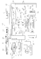
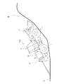
- FIG. 1 is a schematic view showing the configuration of the wheel loader 10 (an example of a working machine) of the present embodiment.
- the wheel loader 10 of the present embodiment has a vehicle body frame 2, a working machine 3, a pair of front tires 4 (an example of wheels), a cab 5, an engine room 6, and a pair of rear tires 7 (of wheels). An example), and a steering cylinder 9.
- “front”, “rear”, “right”, “left”, “top”, and “bottom” indicate directions based on the state of looking forward from the driver's seat.
- vehicle width direction and "left-right direction” are synonymous.
- the front-rear direction is indicated by X
- the front direction is indicated by Xf
- the rear direction is indicated by Xb.
- the vehicle body frame 2, the front tire 4, and the rear tire 7 correspond to an example of a traveling body.
- the wheel loader 10 performs earth and sand loading work using the work machine 3.
- the vehicle body frame 2 is a so-called articulated type, and has a front frame 11, a rear frame 12, and a connecting shaft portion 13.
- the front frame 11 is arranged in front of the rear frame 12.
- the connecting shaft portion 13 is provided at the center in the vehicle width direction, and connects the front frame 11 and the rear frame 12 so as to be swingable with each other.
- the pair of front tires 4 are attached to the left and right sides of the front frame 11. Further, the pair of rear tires 7 are attached to the left and right sides of the rear frame 12.
- the working machine 3 is driven by hydraulic oil from the working machine pump 35b (see FIG. 2).
- the work machine 3 is swingably attached to the front portion of the front frame 11.
- the working machine 3 has a boom 14, a bucket 15, a lift cylinder 16 (an example of a boom cylinder), a bucket cylinder 17 (an example of an actuator), and a bell crank 18 (an example of a sublink).
- the base end of the boom 14 is rotatably attached to the front part of the front frame 11 by the boom pin 14a.
- the tip of the boom 14 is rotatably attached to the rear of the bucket 15.
- the rear of the bucket 15 is on the opposite side of the opening 15b.
- the tip of the cylinder rod 16a of the lift cylinder 16 is rotatably attached between the base end and the tip end of the boom 14.
- the cylinder body of the lift cylinder 16 is rotatably attached to the front frame 11.
- One end of the bell crank 18 is rotatably attached to the tip of the cylinder rod 17a of the bucket cylinder 17.
- the other end of the bell crank 18 is rotatably attached to the rear of the bucket 15.
- the bell crank 18 is rotatably supported between both ends by a bell crank support 14d near the center of the boom 14.
- the cylinder body of the bucket cylinder 17 is rotatably attached to the front frame 11. The expansion and contraction force of the bucket cylinder 17 is converted into rotational motion by the bell crank and transmitted to the bucket 15.
- the bucket 15 is rotatably attached to the tip of the boom 14 by a bucket pin 15a so as to open toward the front. Due to the expansion and contraction of the bucket cylinder 17, the bucket 15 rotates with respect to the boom 14 to perform a tilt operation (see arrow J) and a dump operation (see arrow K).
- the tilting operation of the bucket 15 is an operation of tilting the opening 15b and the claw 15c of the bucket 15 by rotating toward the cab 5.
- the dump operation of the bucket 15 is opposite to the tilt operation, and is an operation of tilting by rotating the opening 15b and the claw 15c of the bucket 15 so as to move away from the cab 5.
- the cab 5 is mounted on the rear frame 12, and a handle for steering operation, a lever for operating the work machine 3, various display devices, and the like are arranged inside.
- the engine room 6 is located on the rear frame 12 behind the cab 5 and houses the engine 31 (see FIG. 2).
- FIG. 2 is a block diagram showing a configuration related to control of the wheel loader 10.
- the wheel loader 10 has a drive system 21, a braking system 22, an operation system 23, a notification system 24, a detection system 25, and a controller 26 (an example of a control unit).
- the drive system 21 drives the wheel loader 10.
- the braking system 22 brakes while the wheel loader 10 is running.
- the operation system 23 is operated by the operator.
- the drive system 21 and the braking system 22 operate based on the operation of the operation system 23 by the operator.
- the notification system 24 notifies the operator based on the operation of the operation system 23 or the detection result by the detection system 25.
- the detection system 25 detects the traveling state, the state of the working machine 3, and the obstacle (an example of an object) behind the vehicle body 1.
- the controller 26 (an example of the control unit) operates the drive system 21, the braking system 22, and the notification system 24 based on the operator's operation on the operation system 23 and the detection by the detection system 25.
- the drive system 21 includes an engine 31, an HST 32, a transfer 33, an axle 34, a front tire 4, a rear tire 7, and a cylinder drive unit 35.
- the engine 31 is, for example, a diesel engine, and the driving force generated by the engine 31 drives the pump 32a of the HST (Hydro Static Transmission) 32.
- HST Hydro Static Transmission
- the HST 32 has a pump 32a, a motor 32b, and a hydraulic circuit 32c connecting the pump 32a and the motor 32b.
- the pump 32a is a swash plate type variable displacement pump, and the angle of the swash plate can be changed by the solenoid 32d.
- the pump 32a is driven by the engine 31 to discharge hydraulic oil.
- the discharged hydraulic oil is sent to the motor 32b through the hydraulic circuit 32c.
- the motor 32b is a swash plate type, and the angle of the swash plate can be changed by the solenoid 32e.
- the hydraulic circuit 32c includes a first drive circuit 32c1 and a second drive circuit 32c2.
- the hydraulic oil is supplied from the pump 32a to the motor 32b via the first drive circuit 32c1, so that the motor 32b is driven in one direction (for example, in the forward direction).
- the hydraulic oil is supplied from the pump 32a to the motor 32b via the second drive circuit 32c2, so that the motor 32b is driven in another direction (for example, in the reverse direction).
- the discharge direction of the hydraulic oil to the first drive circuit 32c1 or the second drive circuit 32c2 can be changed by the solenoid 32d.
- the transfer 33 distributes the output from the engine 31 to the front and rear axles 34.
- a pair of front tires 4 are connected to the axle 34 on the front side, and rotate with the output from the distributed engine 31. Further, a pair of rear tires 7 are connected to the rear axle 34, and rotate with the output from the distributed engine 31.
- the cylinder drive unit 35 has a power take-out unit 35a, a work machine pump 35b, and a control valve 35c.
- the power take-off unit 35a is a PTO (Power Take Off), and for example, with the vehicle body 1 stopped, the output from the engine 31 is taken out and transmitted to the work machine pump 35b.
- the work equipment pump 35b is driven by the power of the engine 31 and discharges hydraulic oil to the control valve 35c.
- the control valve 35c supplies the hydraulic oil supplied from the working machine pump 35b to the lift cylinder 16 (an example of a boom cylinder) and the bucket cylinder 17 based on a command from the controller 26.
- the braking system 22 includes a brake valve 41, a service brake 42, and a parking brake 43.
- the brake valve 41 is, for example, an EPC (Electric Proportional Valve) valve, and the amount of hydraulic oil sent to the service brake 42 can be adjusted by adjusting the opening degree.
- EPC Electronic Proportional Valve
- the service brake 42 is provided on the axle 34.
- the service brake 42 is a hydraulic brake. For example, when the opening degree of the brake valve 41 is large, the braking force becomes strong, and when the opening degree of the brake valve 41 is small, the braking force becomes weak.
- the brake valve 41 is driven by the instruction from the controller 26 and the service brake 42 is operated even when the brake pedal 54 described later is not operated.
- the parking brake 43 is provided on the transfer 33.
- a wet multi-stage brake that can switch between a braking state and a non-braking state a disc brake, and the like can be used.
- the operation system 23 includes an accelerator 51, an FNR lever 52 (an example of an operation member), a parking switch 53, a brake pedal 54, a return switch 55, an automatic brake release switch 56, and an engine key unit 57. ..
- the accelerator 51 is provided in the cab 5. The operator operates the accelerator 51 to set the throttle opening degree. The accelerator 51 generates an opening signal indicating an accelerator operation amount and transmits it to the controller 26. The controller 26 controls the rotation speed of the engine 31 based on the transmitted signal.
- the FNR lever 52 is provided in the cab 5.
- the FNR lever 52 can take a forward, neutral, or reverse position.
- An operation signal indicating the position of the FNR lever 52 is transmitted to the controller 26, and the controller 26 controls the solenoid 32d to switch between forward and reverse.
- the parking switch 53 is provided in the cab 5 and is a switch that can switch the state on and off, and transmits a signal indicating the state to the controller 26.
- the controller 26 puts the parking brake 43 in a braking state or a non-braking state based on the transmitted signal.
- the brake pedal 54 is provided in the cab 5.
- the brake pedal 54 adjusts the opening degree of the brake valve 41. Further, the brake pedal 54 transmits the operation amount to the controller 26.
- the return switch 55 is operated by the operator in order to recover from the stopped state after the vehicle body 1 is stopped by the automatic brake described later.
- the automatic brake release switch 56 releases the automatic brake function and is set so that the automatic brake function does not work.
- the engine key unit 57 By rotating the key, the engine key unit 57 takes three positions: the engine start position, the ACC power on position, and the engine off position. The position information of the engine key unit 57 is transmitted to the controller 26.
- the notification system 24 includes an alarm device 61 (an example of a first notification unit), a function OFF notification lamp 62 (an example of a second notification unit), and an automatic brake operation notification lamp 63.
- the alarm device 61 gives an alarm to the operator when an obstacle is detected behind the vehicle body 1 based on the detection of the rear detection unit 71 of the detection system 25 described later.
- the alarm device 61 may have, for example, a lamp, and the lamp may be turned on. Further, the alarm device 61 may have a speaker and sound a sound, not limited to the lamp. Further, the alarm may be displayed on a display panel such as a monitor.
- the function OFF notification lamp 62 lights up, for example, to notify the operator when the automatic braking function is suppressed or stopped at the discretion of the controller 26. Further, the function OFF notification lamp 62 is turned on, for example, to notify the operator when the automatic brake release switch 56 is operated by the operator's judgment and the automatic brake function is in the OFF state. Further, when the function OFF notification lamp 62 is turned off, it indicates that the automatic braking function can be activated. Further, the function OFF notification lamp 62 is not limited to the lamp, and may make a sound. Further, the notification may be displayed on a display panel such as a monitor.
- the automatic brake operation notification lamp 63 notifies the operator that the automatic brake is operating, and notifies that the return operation by the return switch 55 is necessary. When the return switch 55 is operated and the automatic brake is released, the automatic brake operation notification lamp 63 goes out.
- the automatic brake operation notification lamp 63 does not have to be limited to the lamp, and may make a sound. Further, the notification may be displayed on a display panel such as a monitor.
- the means for notifying the operator of information by the notification system 24 can be appropriately selected such as a lamp, a sound, and a monitor.
- the detection system 25 includes a rear detection unit 71, a traveling state detection unit 72, and a working machine state detection unit 73.
- the rear detection unit 71 detects an obstacle behind the vehicle body 1.
- the rear detection unit 71 is attached to, for example, the rear end of the vehicle body 1 as shown in FIG. 1, but is not limited to the rear end.
- the rear detection unit 71 has, for example, a millimeter wave radar.
- the receiving antenna can detect how the millimeter-wave band radio waves emitted from the transmitting antenna are reflected on the surface of the obstacle and returned, and the distance to the object can be measured.
- the detection result by the rear detection unit 71 is transmitted to the controller 26, and the controller 26 can detect that an obstacle exists within a predetermined range when moving backward.
- the radar is not limited to the millimeter wave radar, and may be, for example, a camera.
- the traveling state detection unit 72 detects the traveling state of the vehicle body 1.
- the traveling state detection unit 72 has a traveling direction sensor 72a and a vehicle speed sensor 72b.
- the traveling direction sensor 72a detects the rotation direction of the front tire 4 or the rear tire 7 and detects whether the vehicle body 1 is in the forward or reverse state.
- the traveling direction sensor 72a can be arranged on the axle 34 or the like, for example, but may be arranged in any configuration of the drive system 21 as long as the traveling state of the vehicle body 1 can be detected. Further, the forward movement or the reverse movement may be determined instead of the traveling direction sensor 72a or based on the position of the FNR lever 52 together with the traveling direction sensor 72a. In this case, the FNR lever 52 is also included in the traveling state detection unit 72.
- the working machine state detection unit 73 detects the state of the working machine 3.
- the work equipment state detection unit 73 has a boom angle sensor 73a (an example of a work equipment height detection unit) and a boom bottom pressure sensor 73b.
- the boom angle sensor 73a detects the angle of the boom 14 and outputs the detected value to the controller 26 (an example of the control unit).
- the boom angle sensor 73a can be configured with a potentiometer and is arranged, for example, on a boom pin 14a.
- the angle of the boom 14 is the angle ⁇ of the straight line Lb extending in the direction from the center of the boom pin 14a toward the center of the bucket pin 15a with respect to the horizontal line Lh extending forward from the center of the boom pin 14a.
- the boom angle is 0 °.
- the angle ⁇ of the boom 14 when the straight line Lb is above the horizontal line Lh is set as a positive value.
- the angle ⁇ of the boom 14 when the straight line Lb is below the horizontal line Lh is set as a negative value.
- the boom angle sensor 73a may be a stroke sensor provided on the lift cylinder 16.
- the boom bottom pressure sensor 73b is attached to the bottom side of the lift cylinder 16. Pressure is applied to the bottom side of the lift cylinder 16, and this pressure causes the cylinder to expand and the boom 14 to rise.
- the boom bottom pressure sensor 73b detects the pressure (bottom pressure) of the hydraulic oil in the oil chamber on the cylinder bottom side of the lift cylinder 16.
- the boom bottom pressure sensor 73b transmits the detected bottom pressure to the controller 26.
- the controller 26 includes a processor and a storage device.
- the processor is, for example, a CPU (Central Processing Unit). Alternatively, the processor may be a processor different from the CPU.
- the processor executes a process for controlling the wheel loader 10 according to a program.
- the storage device includes a non-volatile memory such as ROM (Read Only Memory) and a volatile memory such as RAM (Random Access Memory).
- the storage device may include a hard disk or an auxiliary storage device such as an SSD (Solid State Drive).
- a storage device is an example of a recording medium that can be read by a non-transitory computer.
- the storage device stores programs and data for controlling the wheel loader 10.
- the storage device stores, for example, threshold data described later.
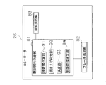
- FIG. 3 is a block diagram showing a configuration of the controller 26.
- the controller 26 has a control execution determination unit 81, a brake instruction unit 82, and a notification instruction unit 83.
- the controller 26 is not limited to one, and may be provided in a plurality of controllers 26, and the functions of the control execution determination unit 81, the brake instruction unit 82, and the notification instruction unit 83 may be provided separately in the plurality of controllers. good.
- the control execution determination unit 81 determines the execution of control of the notification system 24 and the braking system 22.
- the control execution determination unit 81 includes an obstacle determination unit 91, a scraping determination unit 92, a determination unit 93, and a control return determination unit 94.
- the obstacle determination unit 91 determines whether or not an obstacle exists when moving backward.
- the obstacle determination unit 91 is moved backward by either that the front tire 4 or the rear tire 7 is rotating backward by the detection of the traveling direction sensor 72a, or that the FNR lever 52 is in the reverse position. Detects that.
- the obstacle determination unit 91 receives the obstacle detection information within a predetermined range from the rear detection unit 71 of the detection system 25 in the state of detecting the reverse movement, the obstacle determination unit 91 determines that the obstacle exists.
- the scraping determination unit 92 determines whether or not the work content of the wheel loader 10 is scraping work when moving forward.
- the scraping determination unit 92 determines whether or not it is in the excavation work state at the time of advancing, and after the determination of the excavation work state is maintained, determines whether or not it is in the scraping work state.
- FIG. 4 is a diagram showing state transitions of work contents.
- the scraping determination unit 92 determines the excavation work state W1 and the state other than the excavation work W2.
- the scraping determination unit 92 determines that the excavation work state W1 is satisfied when the condition A and the condition B are satisfied at the time of advancing.
- the vehicle body 1 is traveling forward due to the fact that the front tire 4 or the rear tire 7 is rotating forward or the FNR lever 52 is in the forward position (forward state). Judge that.
- the condition (A) is that the boom bottom pressure, which is a value detected by the boom bottom pressure sensor 73b, satisfies the first threshold value or higher.
- the first threshold value is stored in the controller 26.
- the boom bottom pressure becomes equal to or higher than a predetermined threshold value, it can be seen that the lift cylinder 16 is under pressure. That is, at the time of excavation or the like, pressure is applied to the lift cylinder 16 by loading earth and sand into the bucket 15, so that it is possible to determine whether or not the excavation work state is achieved by detecting the boom bottom pressure. ..
- the condition (B) is that the angle ⁇ of the boom 14, which is a value detected by the boom angle sensor 73a, satisfies the second threshold value or less.
- the angle ⁇ of the boom 14 is located below the horizontal state, so that the second threshold value is preferably a negative value.
- the second threshold value is stored in the controller 26.
- the state of the wheel loader 10 is the excavation work state W1. It is judged.
- the scraping determination unit 92 determines that the excavation work state W1 is set, the excavation flag is set to ON and the boom pressure drop flag is set to OFF.
- the scraping determination unit 92 determines whether the excavation work state W1 is the scraping work state W3 or the state other than the scraping work W4. The scraping determination unit 92 determines that the scraping work state W3 is satisfied when the condition (C) is satisfied while the excavation flag is ON, and when the condition (C) is not satisfied, the scraping operation is performed. It is determined that the state is W4 other than the above.
- the condition (C) is that the angle ⁇ of the boom 14, which is a value detected by the boom angle sensor 73a, is larger than the third threshold value.
- the third threshold is, for example, a negative value.
- the third threshold value is set to be larger than the second threshold value.
- the third threshold value is stored in the controller 26.
- the second threshold value indicates when the position of the bucket 15 is close to the tire contact patch.
- the second threshold can be set, for example, ⁇ 40 °.
- the third threshold value indicates when the boom 14 is located at an intermediate level between the horizontal state and the second threshold value state.
- the third threshold can be set, for example, ⁇ 20 °.
- the third threshold value and the second threshold value are set so that the boom 14 at the third threshold value is rotated upward from the boom 14 at the second threshold value.
- the condition (B) and the condition (C) are set based on the magnitude of the angle of the boom 14, but are not limited to this, and are set based on the position of the bucket 15 detected. You may.
- the position of the bucket 15 can be detected by a camera provided in, for example, the cab 5.
- the third threshold value and the second threshold value are set so that the height of the bucket 15 at the third threshold value is higher than the height of the bucket 15 at the second threshold value.
- condition (B) and the condition (C) are set based on the height of the working machine 3, and the height of the working machine 3 at the third threshold value is set higher than the height of the working machine 3 at the second threshold value. It may be set high.
- the scraping determination unit 92 determines that the scraping work state W3 is in effect, the scraping determination unit 92 sets a scraping flag. Further, when the scraping determination unit 92 determines that the condition (C) is not satisfied while the excavation flag is ON, the scraping flag is set to OFF.
- the excavation work state W3 Since the boom 14 is located above during excavation as compared with normal excavation, by detecting the angle ⁇ of the boom 14 in the excavation work state W1, the excavation work state W3 and other than the excavation work are performed.
- the state W4 can be determined.
- the scraping determination unit 92 sets the excavation flag to OFF, assuming that the wheel loader 10 is in a state W2 other than the excavation work. do.
- Condition (D) is that the boom bottom pressure drop flag is in the ON state.
- the boom bottom pressure drop flag is set to ON.
- the boom bottom pressure as a preset threshold value based on the angle ⁇ of the boom 14 is stored in the controller 26.
- the scraping determination unit 92 sets the boom pressure drop flag to ON, and does not perform excavation work. It is determined that the state has changed to W2, and the excavation flag is set to OFF.
- the condition (E) is that the position of the FNR lever 52 is located at a position other than the forward (F) (reverse (N) or neutral (N)).
- the scraping determination unit 92 determines that the state is W2 other than the excavation work, and sets the excavation flag to OFF.
- the scraping determination unit 92 determines that the excavation work state W1 is satisfied by satisfying the condition (A) and the condition (B), the condition (C) is further maintained in the state where the determination is maintained.
- the wheel loader 10 is determined to be in the scraping work state W3, and the scraping flag is set to ON.
- the determination unit 93 determines the control of the notification system 24 and the braking system 22 based on the determination result of the scraping determination unit 92.
- the determination unit 93 is determined by the scraping determination unit 92 that it is not a scraping operation (in FIG. 4, a state W2 other than the excavation work and a state W4 other than the scraping work), the notification system 24 and the braking system 22
- the first control is enabled as the control.
- the automatic brake is activated and an alarm for notifying the existence of the obstacle is issued (of the object).
- An example of responding to detection This is because the wheel loader 10 has not performed the scraping work, and it can be determined that the obstacle detection is not an erroneous detection.
- the determination unit 93 enables the second control as the control of the notification system 24 and the braking system 22.
- the second control does not activate the automatic brake and does not generate an alarm regardless of whether or not the obstacle determination unit 91 determines that an obstacle exists when moving backward.
- the first control is disabled.
- the brake instruction unit 82 controls the automatic brake based on the effective control of the first control or the second control of the determination unit 93.
- the automatic braking in the present specification is to automatically apply a braking force to the vehicle body 1 based on the determination result of the obstacle determination unit 91 and the determination result of the scraping determination unit 92, and is a service as described later. It is not limited to the braking force of the brake 42.
- the brake instruction unit 82 supplies fuel to the engine 31 by turning off the accelerator 51. Stop. Then, the brake instruction unit 82 drives the service brake 42 by operating the brake valve 41 to stop the vehicle body 1.
- the determination unit 93 enables the second control, the function of the automatic brake is stopped, and the brake instruction unit 82 does not operate the brake valve 41 and does not apply the braking force. That is, in the second control, even if the obstacle determination unit 91 determines that an obstacle exists when moving backward, the braking force is not applied.
- the notification instruction unit 83 gives an operation instruction to the alarm device 61 or the function OFF notification lamp 62 based on the effective control of the first control or the second control of the determination unit 93.
- the notification instruction unit 83 operates the alarm device 61 to detect the existence of the obstacle and automatically. Notify the operator of the brake operation.
- the notification instruction unit 83 stops the function of the alarm device 61, lights the function OFF notification lamp 62, and the operator has stopped the automatic braking function. Is notified. That is, in the second control, even if the obstacle determination unit 91 determines that an obstacle exists when moving backward, no alarm is issued.
- FIG. 5 is a diagram showing a state in which the obstacle S is detected when moving backward and the vehicle body 1 is stopped.
- the service brake 42 is operated by a preset braking force (which can be said to be braking force) so that the vehicle body 1 stops in front of the obstacle S, and the vehicle body 1 is stopped.
- the stopped vehicle body 1 is shown by a two-dot chain line.
- the automatic braking by the set braking force does not have to brake the vehicle body 1 by the service brake 42 as described above, and may operate the parking brake 43.
- the brake instruction unit 82 releases the accelerator 51 to the engine 31. Stop the fuel supply. Then, the brake instruction unit 82 controls the parking brake 43 to brake the vehicle body 1.
- FIG. 6 is a diagram showing a state in which the wheel loader 10 is performing the scraping work.
- a pile of earth and sand M is formed on the ground G, and a wheel loader 10 is arranged on the slope i thereof.
- the inclination angle ⁇ is, for example, the angle formed by the line L connecting the axis of the front tire 4 and the axis of the rear tire 7 and the horizontal line H.
- the second control is enabled as the control of the notification system 24 and the braking system 22.
- the function of the automatic brake and the function of the alarm device 61 are stopped, the function OFF notification lamp 62 is turned on, and the automatic brake and the alarm device 61 are not activated.
- the function of the rear detection unit 71 itself may be turned off, or the rear detection unit 71 may perform detection but the controller 26 may not use the detection result, or
- the obstacle determination unit 91 makes a determination using the detection result of the rear detection unit 71, but the determination result may not be used.
- the control return determination unit 94 determines the return from invalidity to valid of the first control based on the information regarding the scraping work state.
- Information about the scraping work state includes the vehicle speed, the position of the FNR lever 52 (an example of an operating member), the mileage, the braking state of the parking brake, or the position of the key.
- the control return determination unit 94 acquires the vehicle speed based on the detection value transmitted from the vehicle speed sensor 72b.
- the control return determination unit 94 acquires the position of the FNR lever 52 (an example of the operation member) by the operation information transmitted from the FNR lever 52.
- the control return determination unit 94 acquires the mileage by calculation using the vehicle speed signal transmitted from the vehicle speed sensor 72b to the controller 26 and the timer included in the controller 26.
- the control return determination unit 94 acquires the braking state of the parking brake 43 by the ON / OFF signal transmitted from the parking switch 53.
- the control return determination unit 94 acquires the position of the key by the position information transmitted from the engine key unit 57.
- control return determination unit 94 determines the return to the validity of the first control when any one of the following conditions (1) to (6) is satisfied.
- the vehicle speed is equal to or higher than the predetermined speed and the FNR lever 52 is placed in the reverse position.
- a predetermined time or more has passed since the FNR lever 52 was placed in the reverse position.
- the FNR lever 52 is in the reverse position.
- the FNR lever 52 has moved from the reverse position to the neutral position or from the reverse position to the forward position (5)
- the parking brake has braked (6)
- the key is OFF.
- control return determination unit 94 controls the notification system 24 and the braking system 22. Instead of the second control, it is determined to return the first control to the effective state.
- control return determination unit 94 determines the return to the effective state of the first control
- the determination unit 93 enables the first control instead of the second control as the control of the notification system 24 and the braking system 22.
- the return to the valid state of the first control is determined based on a condition different from the determination of the scraping work state. It is possible to prevent the ground from being falsely detected as an obstacle when descending a mountain after the scraping work.
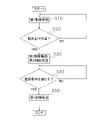
- FIG. 7 is a flow chart showing the control operation of the wheel loader 10 of the present embodiment.
- step S10 an example of a control determination step
- the determination unit 93 of the controller 26 enables the first control as the control of the notification system 24 and the braking system 22.
- the first control when the obstacle determination unit 91 determines that an obstacle exists when moving backward, the automatic brake is activated and an alarm is issued.
- step S20 an example of the scraping determination step
- the scraping determination unit 92 of the controller 26 determines whether or not the vehicle body 1 is in the scraping work state W3. If it is determined in step S20 that the scraping work state is not performed, the control returns to step S10, and the effectiveness of the first control is maintained.
- step S20 determines whether the scraping work state W3 is the scraping work state W3 or not. If it is determined in step S20 that the scraping work state W3, the control proceeds to step S30.
- step S30 (an example of a stop step) the determination unit 93 disables the first control as the control of the notification system 24 and the braking system 22 and enables the second control.
- the function of the automatic brake and the function of the alarm device 61 are stopped, and the function OFF notification lamp 62 is turned on. Therefore, even if it is determined that an obstacle exists when moving backward, the automatic brake and the alarm device 61 are not activated.
- step S40 the control return determination unit 94 determines whether or not any of the above-mentioned conditions (1) to (6) is satisfied based on the information regarding the scraping work state, and the notification system 24 And it is determined whether or not the first control is effectively restored as the control of the braking system 22.
- step S40 is performed until any of the conditions (1) to (6) is satisfied. Repeated. If the control return determination unit 94 determines in step S40 that any one of the conditions (1) to (6) is satisfied, the control proceeds to step S50.
- step S50 the determination unit 93 effectively returns the first control as the control of the notification system 24 and the braking system 22.
- the wheel loader 10 of the first embodiment it is determined whether or not the scraping work state is performed based on the detection by the work machine state detection unit 73, but in the wheel loader 10 of the second embodiment, the vehicle main body is determined. It is determined whether or not the scraping work state is performed based on the tilted state of 1. Further, unlike the condition in which the wheel loader 10 of the first embodiment determines the return to the effective state of the first control, in the wheel loader 10 of the second embodiment, the first control is performed based on the tilted state of the vehicle body 1. Decide to return to validity.
- FIG. 8 is a block diagram showing the configurations of the drive system 21, the braking system 22, the operation system 23, the notification system 24, and the detection system 125 of the wheel loader 10 of the second embodiment.
- the detection system 125 of the wheel loader 10 of the second embodiment is not provided with the traveling state detection unit 72 and the working machine state detection unit 73, and the vehicle body angle.
- a sensor 74 (an example of an inclination state detection unit) is provided.
- the vehicle body angle sensor 74 detects the tilted state of the vehicle body 1.
- the vehicle body angle sensor 74 detects whether or not the vehicle body 1 is in an inclined state by detecting the angle of the vehicle body 1.
- An IMU Inertial Measurement Unit
- the tilted state of the wheel loader 10 may be determined based on the detection images of the cameras installed inside and outside the vehicle body. Further, the configuration is not limited to these configurations as long as it can detect the tilted state of the wheel loader 10.
- the scraping determination unit 92 determines whether or not the scraping work state is achieved based on the detection value of the vehicle body angle sensor 74.
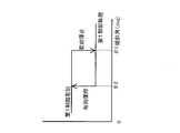
- a predetermined threshold value ⁇ 1 an example of a fourth threshold value, for example, 20 °
- the inclination angle ⁇ is an angle at which the front side of the wheel loader 10 is lifted with respect to the horizontal.
- the control return determination unit 94 when the tilt angle by the vehicle body angle sensor 74 is equal to or less than a predetermined threshold value ⁇ 2 (an example of the fifth threshold value, for example, 10 °), the control return determination unit 94 returns to the effect of the first control. decide. This is because it is considered that the vehicle body 1 is in a state of being descended from an inclined surface where the scraping work is performed.
- the predetermined threshold value ⁇ 2 is set to be smaller than the predetermined threshold value ⁇ 1.
- FIG. 9 is a diagram showing the relationship between the invalidation of the first control with respect to the tilt angle and the return to the effective state.
- the threshold value is set to be smaller than the threshold value ⁇ 1.
- the setting of the first control is restored on the way down from the mountain after the scraping operation, so that the ground G is mistaken for an obstacle. Detect.
- step S20 the scraping determination unit 92 scrapes when the inclination angle by the vehicle body angle sensor 74 is equal to or greater than the predetermined threshold value ⁇ 1. It is determined that it is in the raising work state, and the control proceeds to step S30. On the other hand, when the inclination angle is less than the predetermined threshold value ⁇ 1, it is determined that the scraping work state is not performed, and the control returns to step S10.
- step S40 when the tilt angle by the vehicle body angle sensor 74 is equal to or less than the predetermined threshold value ⁇ 2, the control return determination unit 94 determines that the return condition is satisfied and returns to the effective state of the first control, and the control is performed in step S50. Proceed to. On the other hand, when the inclination angle by the vehicle body angle sensor 74 is larger than the predetermined threshold value ⁇ 2, the control of step S40 is repeated assuming that the return condition is not satisfied, and step S40 is repeated until the return condition is satisfied.
- the wheel loader 10 (an example of a work machine) of the present embodiment includes a vehicle main body 1, a rear detection unit 71, and a controller 26 (an example of a control unit).
- the vehicle body 1 has a vehicle body frame 2, a front tire 4, a rear tire 7 (an example of a traveling body), and a working machine 3 arranged in front of the vehicle body frame 2.
- the rear detection unit 71 detects an obstacle (an example of an object) when traveling backward by driving the vehicle body frame 2, the front tire 4, and the rear tire 7.
- the controller 26 determines whether the first control is valid or invalid depending on the detection of obstacles, the traveling state to the rear, and the scraping work state by the working machine 3, and when the first control is disabled, it is based on the scraping work state. Then, the first control is enabled.
- the first control that takes measures for collision mitigation when an obstacle is detected is invalidated by the determination of the scraping work state, and the first control is disabled when it is no longer necessary to invalidate the first control. Can be restored from invalid to valid.
- the wheel loader 10 (an example of a working machine) of the present embodiment further includes an alarm device 61 (an example of a first notification unit).
- the alarm device 61 notifies that the rear detection unit 71 has detected an obstacle behind the vehicle body 1.
- the controller 26 enables the second control when the first control is disabled.
- the first control executes the notification by the alarm device 61.
- the second control executes the change of the notification by the alarm device 61. Changing the notification includes stopping the notification, suppressing the volume of the notification, or changing the output form of the notification.
- the information regarding the scraping work state includes the vehicle speed, the position of the FNR lever 52 (an example of the operating member), and the mileage.
- the controller 26 has an FNR lever when the vehicle speed is equal to or higher than a predetermined speed and the FNR lever 52 is arranged in the reverse position, or when a predetermined time or more has elapsed since the FNR lever 52 was arranged in the reverse position.
- the first control is enabled in any case of traveling for a predetermined distance or more after the 52 is arranged in the reverse position.
- the information regarding the scraping work state is the position of the FNR lever 52 (an example of an operation member), the braking state of the parking brake 43, or the engine key portion 57 (key).
- An example includes the ON / OFF state.
- the controller 26 moves the FNR lever 52 from the reverse position to the neutral position or moves from the reverse position to the forward position, when the parking brake 43 brakes, or when the engine key portion 57 is in the OFF state.
- the first control is enabled in any of the cases where it becomes.
- the wheel loader 10 (an example of a working machine) of the present embodiment includes a traveling state detecting unit 72 and a working machine state detecting unit 73.
- the traveling state detection unit 72 detects the traveling state of the vehicle body 1.
- the working machine state detection unit 73 detects the state of the working machine 3.
- the information regarding the scraping work state includes the running state and the state of the working machine 3.
- the controller 26 determines whether or not it is in the scraping work state based on the state of the work machine 3 when moving forward.
- the working machine 3 has a boom 14, a bucket 15, and a lift cylinder 16 (an example of a boom cylinder).
- the boom 14 is operably attached to the front portion of the vehicle body frame 2.
- the bucket 15 is connected to the boom 14 so that the opening is arranged toward the front, and drives the boom 14.
- the lift cylinder 16 drives the boom 14.
- the work equipment state detection unit 73 includes a boom bottom pressure sensor 73b and a boom angle sensor 73a.
- the boom bottom pressure sensor 73b detects the bottom pressure of the lift cylinder 16.
- the boom angle sensor 73a detects the angle of the boom 14.
- the controller 26 determines whether or not it is in the scraping work state based on the bottom pressure of the lift cylinder 16 and the angle of the boom 14.
- the controller 26 is in an excavation work state when the bottom pressure of the lift cylinder 16 is equal to or higher than the first threshold value and the angle of the boom 14 is equal to or lower than the second threshold value.
- the angle of the boom 14 is larger than the third threshold value during the determination of the excavation work state, it is determined that the boom 14 is in the scraping work state.
- the third threshold is located above the second threshold.
- the traveling state detection unit 72 sets the rotation direction of the front tire 4 or the rear tire 7 provided on the vehicle body 1, or the forward or reverse direction of the vehicle body 1.
- the possible FNR lever 52 detects the set position.
- the controller 26 determines forward movement based on the detection of the traveling state detection unit 72.
- the wheel loader 10 (an example of a work machine) of the present embodiment further includes a vehicle body angle sensor 74 (an example of an inclination state detection unit).
- the vehicle body angle sensor 74 detects the tilted state of the vehicle body 1.
- Information about the scraping work state includes the tilted state.
- the controller 26 determines that the vehicle body 1 is in the scraped-up state when the inclination angle of the vehicle body 1 is equal to or greater than the fourth threshold value.
- the vehicle body 1 Since the vehicle body 1 is arranged in an inclined place such as a mountain of earth and sand during the scraping work, it is possible to determine whether or not the scraping work state is achieved by detecting the tilt.
- the information regarding the scraping work state includes an inclined state.
- the controller 26 enables the first control when the tilt angle of the vehicle body 1 is equal to or less than the fifth threshold value smaller than the fourth threshold value.
- the magnitudes of the fourth threshold value of the tilt angle used for determining whether or not the scraping work state is set and the fifth threshold value of the tilt angle for returning the first control for performing the operation for collision mitigation are changed.
- the fifth threshold value By setting the fifth threshold value to be smaller than the fourth threshold value, it is possible to reduce erroneous detection on the way down the mountain.
- the wheel loader 10 (an example of a work machine) of the present embodiment further includes a traveling state detecting unit 72 for detecting the traveling state of the vehicle body 1.
- the controller 26 detects an object behind the vehicle body 1 when moving backward.
- the traveling state detection unit 72 detects the rotation direction of the front tire 4 or the rear tire 7 provided on the vehicle body 1, or the position where the FNR lever 52 capable of setting the forward or backward movement of the vehicle body 1 is set.
- the controller 26 determines the reverse movement based on the detection of the traveling state detection unit 72.
- the controller 26 enables the second control when the first control is disabled.
- the first control executes the drive of the automatic brake in order to automatically brake the vehicle body 1.
- the second control executes the suppression of the braking force of the automatic brake or the stop of the automatic brake.
- the wheel loader 10 (an example of a work machine) of the present embodiment further includes a function OFF notification lamp 62 (an example of a second notification unit) for notifying the suppression of the braking force of the automatic brake or the stop of the automatic brake.
- a function OFF notification lamp 62 an example of a second notification unit for notifying the suppression of the braking force of the automatic brake or the stop of the automatic brake.
- the working machine 3 includes a boom 14, a bucket 15, a bucket cylinder 17 (an example of an actuator), a bell crank 18 (an example of a sublink), and a bell crank 18.
- the boom 14 is swingably attached to the front portion of the vehicle body frame 2.
- the bucket 15 is connected to the boom 14 so that the opening is arranged toward the front, and drives the boom 14.
- the bucket cylinder 17 drives the bucket 15.
- the bell crank 18 is attached to the boom 14 and transmits the driving force of the bucket cylinder 17 to the bucket 15.
- the control method of the wheel loader 10 (an example of a work machine) of the present embodiment includes steps S10 and S30 (an example of a control determination step) and steps S40 and S50 (an example of a control effective step).
- Steps S10 and S30 detect an object when traveling backward by driving the traveling body of the vehicle body 1 having the vehicle body frame 2, the front tire 4, the rear tire 7 (an example of the traveling body) and the working machine 3.
- the validity or invalidity of the first control is determined according to the traveling state to the rear and the scraping work state by the working machine 3.
- Steps S40 and S50 enable the first control based on the scraping work state when the first control is disabled.
- the first control that takes measures for collision mitigation when an obstacle is detected is invalidated by the determination of the scraping work state, and the first control is disabled when it is no longer necessary to invalidate the first control. Can be restored from invalid to valid.
- the function of the automatic brake is stopped in the second control, but it is not limited to the stop, and the opening degree of the brake valve 41 is set smaller than that in the first control to perform the automatic braking. It may be controlled so that a weaker braking force is applied. This weak brake corresponds to an example of suppression of automatic braking. At this time, the suppression of the automatic braking may be notified by the function OFF notification lamp 62.
- the weak braking force may be generated by the operator performing control when the accelerator 51 is turned off instead of adjusting the opening degree of the brake valve 41.
- the brake instruction unit 82 may stop the fuel supply to the engine 31 and control the swash plate of the pump 32a and the motor 32b so as to be a running resistance.
- the controller 26 controls the solenoids 32d and 32e, and the swash plate of the pump 32a and the motor 32b moves so as to be a running resistance. That is, the brake instruction unit 82 may stop the fuel supply to the engine 31 and control the swash plate of the pump 32a and the motor 32b so as to be a running resistance.
- the braking force works and a weak braking force is generated. It should be noted that the neutral type can obtain a larger braking force than the accelerator 51 is simply released.
- the HST 32 is used for the drive system 21, but it is not limited to the HST and may be a torque converter.
- FIG. 11 is a block diagram showing a configuration in which the torque converter 132 and the transmission 133 are provided in the drive system 21. Although FIG. 11 is described as a modification of the configuration of the second embodiment, a configuration in which the torque converter 132 and the transmission 133 are provided in the drive system 21 may be applied to the first embodiment.
- the driving force from the engine 31 is transmitted to the transmission 133 via the torque converter 132.
- the transmission 133 shifts the rotational driving force of the engine 31 transmitted via the torque converter 132 and transmits it to the axle 34.
- the transmission 133 is provided with a parking brake 43.
- the opening degree of the brake valve 41 may be set small in the same manner as described above. Further, although the braking force is weaker than that of the HST, it may be sufficient to simply control the accelerator 51 to be in the off state. When the set braking force is generated, the opening degree of the brake valve 41 may be increased or the parking brake 43 may be used, as in the above embodiment.
- HST Hydro Mechanical Transmission
- HMT Hydro Mechanical Transmission
- the automatic brake in the second control, is not activated and the alarm device 61 is not activated, but for example, only the alarm device 61 may be operated. Further, only the automatic brake may be operated, or both the automatic brake and the alarm device 61 may be operated. When both are operated, unlike the first control, the second control may suppress the braking force of the automatic brake, suppress the magnitude of the alarm of the alarm device 61, and the like.
- the wheel loader 10 of the above embodiment has an automatic braking function, but may not have an automatic braking function.
- the automatic brake does not operate and the alarm device 61 operates. Further, in the second control, the alarm device 61 is not operated.
- the alarm volume may be changed according to the distance from the vehicle body 1 to the obstacle.
- a service brake 42, a parking brake 43, and other means for changing the braking force can be appropriately applied.
- the scraping work state determination condition in the first embodiment and the return condition in the second embodiment may be combined, and conversely, the scraping work state determination condition in the second embodiment and the first embodiment may be combined.
- the return conditions may be combined.
- the determination conditions of the scraping work state in the first embodiment and the second embodiment may be combined, or the return conditions in the first embodiment and the second embodiment may be combined.
- the condition (1) to (6) is added as the return condition
- the condition (7) is that the inclination angle is the threshold value ⁇ 2 or less
- the condition (1) to (7) is satisfied. The conditions may be satisfied.
- the function OFF notification lamp 62 is always lit in the second control, but the function OFF notification lamp 62 may be lit only when an obstacle is detected during reverse movement.
- the wheel loader of the above embodiment may be operated by an operator on board, or may be operated unattended.
- the wheel loader has been described as an example of the work machine, but the present invention is not limited to this, and a bulldozer, a forklift, or the like may be used.
- the work machine and the control method of the work machine of the present disclosure it is useful as a wheel loader or the like because it exerts an effect that it is possible to give an alarm in consideration of the withdrawal of the scraping work.
- Vehicle body 2 Body frame 3: Working machine 4: Front tire 7: Rear tire 26: Controller 71: Rear detector
Landscapes
- Engineering & Computer Science (AREA)
- Mining & Mineral Resources (AREA)
- Civil Engineering (AREA)
- General Engineering & Computer Science (AREA)
- Structural Engineering (AREA)
- Mechanical Engineering (AREA)
- Transportation (AREA)
- Operation Control Of Excavators (AREA)
- Component Parts Of Construction Machinery (AREA)
Abstract
Description
(課題を解決するための手段)
(発明の効果)
(ホイールローダの概要)
図1は、本実施の形態のホイールローダ10(作業機械の一例)の構成を示す模式図である。本実施の形態のホイールローダ10は、車両本体1に、車体フレーム2と、作業機3と、一対のフロントタイヤ4(車輪の一例)、キャブ5、エンジンルーム6、一対のリアタイヤ7(車輪の一例)、およびステアリングシリンダ9と、を備えている。なお、以下の説明において、「前」、「後」、「右」、「左」、「上」、及び「下」とは運転席から前方を見た状態を基準とする方向を示す。また、「車幅方向」と「左右方向」は同義である。図1では、前後方向をXで示し、前方向を示すときはXf、後方向を示すときはXbで示す。また、車体フレーム2、フロントタイヤ4、およびリアタイヤ7は、走行体の一例に相当する。
図2は、ホイールローダ10の制御に関する構成を示すブロック図である。
駆動系21は、エンジン31と、HST32と、トランスファ33と、アクスル34と、フロントタイヤ4およびリアタイヤ7と、シリンダ駆動部35と、を有する。
制動系22は、ブレーキ弁41と、サービスブレーキ42と、パーキングブレーキ43と、を有する。
操作系23は、アクセル51と、FNRレバー52(操作部材の一例)と、パーキングスイッチ53と、ブレーキペダル54と、復帰スイッチ55と、自動ブレーキ解除スイッチ56と、エンジンキー部57と、を有する。
報知系24は、警報装置61(第1報知部の一例)と、機能OFF通知ランプ62(第2報知部の一例)と、自動ブレーキ作動通知ランプ63と、を有する。
検出系25は、図2に示すように、後方検出部71と、走行状態検出部72と、作業機状態検出部73と、を有する。
コントローラ26は、プロセッサと、記憶装置を含む。プロセッサは、例えばCPU(Central Processing Unit)である。或いは、プロセッサは、CPUと異なるプロセッサであってもよい。プロセッサは、プログラムに従ってホイールローダ10の制御のための処理を実行する。記憶装置は、ROM(Read Only Memory)のような不揮発性メモリおよびRAM(Random Access Memory)のような揮発性メモリを含む。記憶装置は、ハードディスク、あるいはSSD(Solid State Drive)などの補助記憶装置を含んでいてもよい。記憶装置は、非一時的な(non-transitory)コンピュータで読み取り可能な記録媒体の一例である。記憶装置は、ホイールローダ10を制御するためのプログラムおよびデータを記憶している。記憶装置は、例えば、後述する閾値のデータを記憶している
図3は、コントローラ26の構成を示すブロック図である。
(2)FNRレバー52が後進位置に配置されてから所定時間以上経過したこと
(3)FNRレバー52が後進位置に配置されてから所定距離以上走行したこと
(4)FNRレバー52が後進位置から中立位置に移動若しくは後進位置から前進位置に移動したこと
(5)パーキングブレーキが制動したこと
(6)キーがOFF状態になったこと
上記条件(1)~(3)のいずれかを満たした場合、ホイールローダ10が掻き上げ作業後に土砂の山から降りた状態であると考えられるため、制御復帰決定部94は、報知系24と制動系22の制御として第2制御の代わりに第1制御を有効へ復帰することを決定する。また、条件(4)~(6)のいずれかを満たした場合、何かの理由によってホイールローダ10を停止したと考えられるため、制御復帰決定部94は、報知系24と制動系22の制御として第2制御の代わりに第1制御の有効への復帰を決定する。
次に、本実施の形態のホイールローダ10の制御動作について説明する。
次に、本開示にかかる実施の形態2のホイールローダ10について説明する。
(1)
本実施の形態のホイールローダ10(作業機械の一例)は、車両本体1と、後方検出部71と、コントローラ26(制御部の一例)と、を備える。車両本体1は、車体フレーム2、フロントタイヤ4、およびリアタイヤ7(走行体の一例)と、車体フレーム2の前方に配置された作業機3と、を有する。後方検出部71は、車体フレーム2、フロントタイヤ4、およびリアタイヤ7の駆動による後方への走行の際に障害物(物体の一例)を検出する。コントローラ26は、障害物の検出と、後方への走行状態と、作業機3による掻き上げ作業状態により第1制御の有効または無効を決定し、第1制御の無効時に、掻き上げ作業状態に基づいて、第1制御を有効にする。
本実施の形態のホイールローダ10(作業機械の一例)は、警報装置61(第1報知部の一例)を更に備える。警報装置61は、後方検出部71によって車両本体1の後方に障害物を検出したことを報知する。コントローラ26は、第1制御の無効時に第2制御を有効にする。第1制御は、警報装置61による報知を実行する。第2制御は、警報装置61による報知の変更を実行する。報知の変更は、報知の停止、報知の音量の抑制、または報知の出力形態を変更することを含む。
本実施の形態のホイールローダ10(作業機械の一例)では、掻き上げ作業状態に関する情報は、車速、FNRレバー52(操作部材の一例)の位置、走行距離を含む。コントローラ26は、第1制御の無効時に、車速が所定速度以上且つFNRレバー52が後進位置に配置されている場合、FNRレバー52が後進位置に配置されてから所定時間以上経過した場合、FNRレバー52が後進位置に配置されてから所定距離以上走行した場合のいずれかの場合に第1制御を有効にする。
本実施の形態のホイールローダ10(作業機械の一例)では、掻き上げ作業状態に関する情報は、FNRレバー52(操作部材の一例)の位置、パーキングブレーキ43の制動状態、またはエンジンキー部57(キーの一例)のON・OFF状態を含む。コントローラ26は、第1制御の無効時に、FNRレバー52が後進位置から中立位置に移動若しくは後進位置から前進位置に移動した場合、パーキングブレーキ43が制動した場合、またはエンジンキー部57がOFF状態になった場合のいずれかの場合に第1制御を有効にする。
本実施の形態のホイールローダ10(作業機械の一例)は、走行状態検出部72と、作業機状態検出部73と、を備える。走行状態検出部72は、車両本体1の走行状態を検出する。作業機状態検出部73は、作業機3の状態を検出する。掻き上げ作業状態に関する情報は、走行状態、および作業機3の状態を含む。コントローラ26は、前進時に作業機3の状態に基づいて、掻き上げ作業状態であるか否かを判定する。
本実施の形態のホイールローダ10(作業機械の一例)では、作業機3は、ブーム14と、バケット15と、リフトシリンダ16(ブームシリンダの一例)と、を有する。ブーム14は、車体フレーム2の前部に動作可能に取り付けられている。バケット15は、前方に向かって開口が配置されるようにブーム14に接続され、ブーム14に対して駆動する。リフトシリンダ16は、ブーム14を駆動する。作業機状態検出部73は、ブームボトム圧センサ73bと、ブーム角度センサ73aと、を備える。ブームボトム圧センサ73bは、リフトシリンダ16のボトム圧を検出する。ブーム角度センサ73aは、ブーム14の角度を検出する。コントローラ26は、リフトシリンダ16のボトム圧とブーム14の角度に基づいて、掻き上げ作業状態であるか否かの判定を行う。
本実施の形態のホイールローダ10(作業機械の一例)では、コントローラ26は、リフトシリンダ16のボトム圧が第1閾値以上、且つブーム14の角度が第2閾値以下の場合に掘削作業状態であると判定し、掘削作業状態との判定中にブーム14の角度が第3閾値より大きいとき、掻き上げ作業状態であると判定する。第3閾値は、第2閾値よりも上方に位置する。
本実施の形態のホイールローダ10(作業機械の一例)では、走行状態検出部72は、車両本体1に設けられたフロントタイヤ4またはリアタイヤ7の回転方向、または車両本体1の前進または後進を設定可能なFNRレバー52が設定された位置を検出する。コントローラ26は、走行状態検出部72の検出に基づいて前進を判定する。
本実施の形態のホイールローダ10(作業機械の一例)は、車体角度センサ74(傾斜状態検出部の一例)を更に備える。車体角度センサ74は、車両本体1の傾斜状態を検出する。掻き上げ作業状態に関する情報は、傾斜状態を含む。コントローラ26は、車両本体1の傾斜角度が第4閾値以上の場合に、掻き上げ状態であると判定する。
本実施の形態のホイールローダ10(作業機械の一例)では、掻き上げ作業状態に関する情報は、傾斜状態を含む。コントローラ26は、第1制御の無効時に、車両本体1の傾斜角度が第4閾値よりも小さい第5閾値以下の場合に、第1制御を有効にする。
本実施の形態のホイールローダ10(作業機械の一例)は、車両本体1の走行状態を検出する走行状態検出部72を更に備える。コントローラ26は、車両本体1の後方の物体の検出を後進時に実行する。走行状態検出部72は、車両本体1に設けられたフロントタイヤ4またはリアタイヤ7の回転方向、または車両本体1の前進または後進を設定可能なFNRレバー52が設定された位置を検出する。コントローラ26は、走行状態検出部72の検出に基づいて後進を判定する。
本実施の形態のホイールローダ10(作業機械の一例)では、コントローラ26は、第1制御の無効時に第2制御を有効にする。第1制御は、車両本体1を自動的に制動するために自動ブレーキの駆動を実行する。第2制御は、自動ブレーキの制動力の抑制、または自動ブレーキの停止を実行する。
本実施の形態のホイールローダ10(作業機械の一例)は、自動ブレーキの制動力の抑制または自動ブレーキの停止を報知する機能OFF通知ランプ62(第2報知部の一例)を更に備える。コントローラ26は、自動ブレーキの制動力の抑制または自動ブレーキの停止を行った場合、機能OFF通知ランプ62によってオペレータに報知を行う。
本実施の形態のホイールローダ10(作業機械の一例)では、作業機3は、ブーム14と、バケット15と、バケットシリンダ17(アクチュエータの一例)と、ベルクランク18(サブリンクの一例)と、を備える。ブーム14は、車体フレーム2の前部に揺動可能に取り付けられている。バケット15は、前方に向かって開口が配置されるようにブーム14に接続され、ブーム14に対して駆動する。バケットシリンダ17は、バケット15を駆動する。ベルクランク18は、ブーム14に取り付けられ、バケットシリンダ17の駆動力をバケット15へ伝達する。
本実施の形態のホイールローダ10(作業機械の一例)の制御方法は、ステップS10、ステップS30(制御決定ステップの一例)と、ステップS40、S50(制御有効ステップの一例)と、を備える。ステップS10、S30は、車体フレーム2、フロントタイヤ4、およびリアタイヤ7(走行体の一例)と作業機3を有する車両本体1の走行体の駆動による後方への走行の際における物体の検出と、後方への走行状態と、作業機3による掻き上げ作業状態により第1制御の有効または無効を決定する。ステップS40、S50は、第1制御の無効時に、掻き上げ作業状態に基づいて、第1制御を有効にする。
以上、本発明の一実施形態について説明したが、本発明は上記実施形態に限定されるものではなく、発明の要旨を逸脱しない範囲で種々の変更が可能である。
上記実施の形態では、第2制御において自動ブレーキの機能を停止していたが、停止に限らなくても良く、第1制御のときよりもブレーキ弁41の開度を小さく設定して自動ブレーキのときよりも弱いブレーキ力が作動するように制御してもよい。この弱いブレーキが、自動ブレーキの抑制の一例に対応する。このとき、自動ブレーキの抑制を、機能OFF通知ランプ62で通知してもよい。
上記実施の形態では、駆動系21にHST32を用いているが、HSTに限らなくても良く、トルクコンバータであってもよい。図11は、駆動系21にトルクコンバータ132とトランスミッション133が設けられた構成を示すブロック図である。図11は、実施の形態2の構成の変形例として記載しているが、駆動系21にトルクコンバータ132とトランスミッション133が設けられた構成を実施の形態1に適用してもよい。
上記実施の形態では、第2制御において、自動ブレーキを作動させず、警報装置61も作動させていないが、例えば警報装置61のみ動作させてもよい。また、自動ブレーキのみ作動させてもよく、自動ブレーキおよび警報装置61の双方を作動させてもよい。双方を作動させる場合は、第1制御と異なるように、第2制御では、自動ブレーキの制動力の抑制や、警報装置61の警報の大きさの抑制等が行ってもよい。
上記実施の形態のホイールローダ10は、自動ブレーキの機能を有しているが、自動ブレーキの機能を有していなくてもよい。この場合、第1制御では、自動ブレーキが作動せず、警報装置61が作動する。また、第2制御では、警報装置61の作動は行われない。
上記実施の形態では、警報装置61の報知の変更の一例として第2制御において、警報装置61による警報を停止させているが、これに限らず、警報の音量を抑制してもよく、警報の出力形態を変更してもよい。警報の出力形態を変更するとは、例えば、音による報知を光による報知に変更することである。
なお、制動力の制御は、サービスブレーキ42、パーキングブレーキ43、他に制動力を変更する手段を適宜適用できる。
上記実施の形態1における掻き上げ作業状態の判定条件と、実施の形態2における復帰条件を組み合わせてもよく、逆に、実施の形態2における掻き上げ作業状態の判定条件と、実施の形態1における復帰条件を組み合わせてもよい。
上記実施の形態では、第2制御において機能OFF通知ランプ62を常時点灯させているが、後進時に障害物を検出したときにのみ機能OFF通知ランプ62を点灯させていてもよい。
上記実施の形態のホイールローダはオペレータが搭乗して操作してもよいし、無人で操作されてもよい。
上記実施の形態では、作業機械の一例としてホイールローダを用いて説明したが、これに限られるものではなく、ブルドーザ、フォークリフト等であってもよい。
2 :車体フレーム
3 :作業機
4 :フロントタイヤ
7 :リアタイヤ
26 :コントローラ
71 :後方検出部
Claims (15)
- 走行体と、前記走行体の前方に配置された作業機と、有する車両本体と、
前記走行体の駆動による後方への走行の際に物体を検出する後方検出部と、
前記物体の検出と、前記後方への走行状態と、前記作業機による掻き上げ作業状態により第1制御の有効または無効を決定し、
前記第1制御の無効時に、前記掻き上げ作業状態に基づいて、前記第1制御を有効にする制御部と、を備えた、
作業機械。 - 前記後方検出部によって前記車両本体の後方に物体を検出したことを報知する第1報知部を更に備え、
前記制御部は、前記第1制御の無効時に第2制御を有効にし、
前記第1制御は、前記第1報知部による報知を実行し、
前記第2制御は、前記第1報知部による報知の変更を実行し、
前記報知の変更は、報知の停止、報知の音量の抑制、または報知の出力形態を変更することを含む、
請求項1に記載の作業機械。 - 前記掻き上げ作業状態に関する情報は、車速、操作部材の位置、または走行距離を含み、
前記制御部は、前記第1制御の無効時に、前記車速が所定速度以上且つ前記操作部材が後進位置に配置されている場合、前記操作部材が後進位置に配置されてから所定時間以上経過した場合、または前記操作部材が後進位置に配置されてから所定距離以上走行した場合のいずれかの場合に前記第1制御を有効にする、
請求項1または2に記載の作業機械。 - 前記掻き上げ作業状態に関する情報は、操作部材の位置、パーキングブレーキの制動状態、またはキーのON・OFF状態を含み、
前記制御部は、前記第1制御の無効時に、前記操作部材が後進位置から中立位置に移動若しくは後進位置から前進位置に移動した場合、前記パーキングブレーキが制動した場合、または前記キーが前記OFF状態になった場合のいずれかの場合に前記第1制御を有効にする、
請求項1または2に記載の作業機械。 - 前記車両本体の走行状態を検出する走行状態検出部と、
前記作業機の状態を検出する作業機状態検出部と、を更に備え、
前記掻き上げ作業状態に関する情報は、前記走行状態、および前記作業機の状態を含み、
前記制御部は、前進時に前記作業機の状態に基づいて、前記掻き上げ作業状態であるか否かを判定する、
請求項1~4のいずれか1項に記載の作業機械。 - 前記作業機は、
前記走行体の前部に動作可能に取り付けられたブームと、
前方に向かって開口が配置されるように前記ブームに接続され、前記ブームに対して駆動するバケットと、
前記ブームを駆動するブームシリンダと、を有し、
前記作業機状態検出部は、
前記ブームシリンダのボトム圧を検出するブームボトム圧センサと、
前記ブームの角度を検出するブーム角度センサと、を更に備え、
前記制御部は、前記ブームシリンダのボトム圧と前記ブームの角度に基づいて、前記掻き上げ作業状態であるか否かの判定を行う、
請求項5に記載の作業機械。 - 前記制御部は、
前記ブームシリンダのボトム圧が第1閾値以上、且つ前記ブームの角度が第2閾値以下の場合に掘削作業状態であると判定し、前記掘削作業状態との判定中に前記ブームの角度が第3閾値より大きいとき、前記掻き上げ作業状態であると判定し、
前記第3閾値は、前記第2閾値よりも上方に位置する、
請求項6に記載の作業機械。 - 前記走行状態検出部は、前記車両本体に設けられた車輪の回転方向、または前記車両本体の前進または後進を設定可能な操作部材が設定された位置を検出し、
前記制御部は、前記走行状態検出部の検出に基づいて前進を判定する、
請求項5~7のいずれか1項に記載の作業機械。 - 前記車両本体の傾斜状態を検出する傾斜状態検出部を更に備え、
前記掻き上げ作業状態に関する情報は、前記傾斜状態を含み、
前記制御部は、前記車両本体の傾斜角度が第4閾値以上の場合に、前記掻き上げ作業状態であると判定する、
請求項1に記載の作業機械。 - 前記掻き上げ作業状態に関する情報は、前記傾斜状態を含み、
前記制御部は、前記第1制御の無効時に、前記車両本体の傾斜角度が前記第4閾値よりも小さい第5閾値以下の場合に、前記第1制御を有効にする、
請求項9に記載の作業機械。 - 前記車両本体の走行状態を検出する走行状態検出部を更に備え、
前記制御部は、前記車両本体の後方の物体の検出を後進時に実行し、
前記走行状態検出部は、前記車両本体に設けられた車輪の回転方向、または前記車両本体の前進または後進を設定可能な操作部材が設定された位置を検出し、
前記制御部は、前記走行状態検出部の検出に基づいて後進を判定する、
請求項1に記載の作業機械。 - 前記制御部は、前記第1制御の無効時に第2制御を有効にし、
前記第1制御は、前記車両本体を自動的に制動するために自動ブレーキの駆動を実行し、
前記第2制御は、前記自動ブレーキの制動力の抑制、または前記自動ブレーキの停止を実行する、
請求項1に記載の作業機械。 - 前記自動ブレーキの制動力の抑制または前記自動ブレーキの停止を報知する第2報知部を更に備え、
前記制御部は、前記自動ブレーキの制動力の抑制または前記自動ブレーキの停止を行った場合、前記第2報知部によってオペレータに報知を行う、
請求項12に記載の作業機械。 - 前記作業機械は、ホイールローダであって、
前記作業機は、
前記走行体の前部に揺動可能に取り付けられたブームと、
前方に向かって開口が配置されるように前記ブームに接続され、前記ブームに対して駆動するバケットと、
前記バケットを駆動するアクチュエータと、
前記ブームに取り付けられ、前記アクチュエータの駆動力を前記バケットへ伝達するサブリンクと、を備えた、請求項1~5および9~11のいずれか1項に記載の作業機械。 - 走行体と作業機を有する車両本体の走行体の駆動による後方への走行の際における物体の検出と、後方への走行状態と、前記作業機による掻き上げ作業状態により第1制御の有効または無効を決定する制御決定ステップと、
前記第1制御の無効時に、前記掻き上げ作業状態に基づいて、前記第1制御を有効にする制御有効ステップと、を備えた、
作業機械の制御方法。
Priority Applications (4)
| Application Number | Priority Date | Filing Date | Title |
|---|---|---|---|
| US18/004,352 US12428819B2 (en) | 2020-09-30 | 2021-07-19 | Work machine and method for controlling work machine |
| EP21874865.5A EP4166727A4 (en) | 2020-09-30 | 2021-07-19 | CONSTRUCTION MACHINERY AND METHOD FOR CONTROLLING CONSTRUCTION MACHINERY |
| CN202180043275.1A CN115698437B (zh) | 2020-09-30 | 2021-07-19 | 工程机械及工程机械的控制方法 |
| US19/314,481 US20250382774A1 (en) | 2020-09-30 | 2025-08-29 | Work machine and method for controlling work machine |
Applications Claiming Priority (2)
| Application Number | Priority Date | Filing Date | Title |
|---|---|---|---|
| JP2020165072A JP7481983B2 (ja) | 2020-09-30 | 2020-09-30 | 作業機械および作業機械の制御方法 |
| JP2020-165072 | 2020-09-30 |
Related Child Applications (2)
| Application Number | Title | Priority Date | Filing Date |
|---|---|---|---|
| US18/004,352 A-371-Of-International US12428819B2 (en) | 2020-09-30 | 2021-07-19 | Work machine and method for controlling work machine |
| US19/314,481 Continuation US20250382774A1 (en) | 2020-09-30 | 2025-08-29 | Work machine and method for controlling work machine |
Publications (1)
| Publication Number | Publication Date |
|---|---|
| WO2022070561A1 true WO2022070561A1 (ja) | 2022-04-07 |
Family
ID=80949832
Family Applications (1)
| Application Number | Title | Priority Date | Filing Date |
|---|---|---|---|
| PCT/JP2021/027009 Ceased WO2022070561A1 (ja) | 2020-09-30 | 2021-07-19 | 作業機械および作業機械の制御方法 |
Country Status (5)
| Country | Link |
|---|---|
| US (2) | US12428819B2 (ja) |
| EP (1) | EP4166727A4 (ja) |
| JP (1) | JP7481983B2 (ja) |
| CN (1) | CN115698437B (ja) |
| WO (1) | WO2022070561A1 (ja) |
Families Citing this family (8)
| Publication number | Priority date | Publication date | Assignee | Title |
|---|---|---|---|---|
| JP2024024251A (ja) * | 2022-08-09 | 2024-02-22 | 株式会社小松製作所 | 作業機械システムおよび作業機械の制御方法 |
| JP2024068558A (ja) * | 2022-11-08 | 2024-05-20 | 株式会社小松製作所 | 作業機械の作業状態推定システムおよび作業機械の作業状態推定方法 |
| JP2024085103A (ja) * | 2022-12-14 | 2024-06-26 | 株式会社小松製作所 | 作業機械を含むシステム、作業機械の制御方法、および作業機械のコントローラ |
| JP2024085104A (ja) * | 2022-12-14 | 2024-06-26 | 株式会社小松製作所 | 作業機械を含むシステム、作業機械の制御方法、および作業機械のコントローラ |
| JP2024085102A (ja) * | 2022-12-14 | 2024-06-26 | 株式会社小松製作所 | 作業機械を含むシステム、作業機械の制御方法、および作業機械のコントローラ |
| GB2638694A (en) * | 2024-02-27 | 2025-09-03 | Bamford Excavators Ltd | Axle assembly |
| WO2025205826A1 (ja) * | 2024-03-26 | 2025-10-02 | 株式会社小松製作所 | 作業機械、作業機械のシステムおよび作業機械の制御方法 |
| CN119266326B (zh) * | 2024-09-29 | 2025-11-11 | 徐工集团工程机械股份有限公司科技分公司 | 一种电动装载机安全控制方法、系统、存储介质及设备 |
Citations (8)
| Publication number | Priority date | Publication date | Assignee | Title |
|---|---|---|---|---|
| JP3219005B2 (ja) | 1996-08-13 | 2001-10-15 | 日本電気株式会社 | 負性抵抗増幅器 |
| JP2003034232A (ja) * | 2001-07-24 | 2003-02-04 | Komatsu Ltd | 移動体の始動ロック装置 |
| US20170121929A1 (en) * | 2015-10-30 | 2017-05-04 | Deere & Company | System and method for assisted bucket load operation |
| JP2018044381A (ja) * | 2016-09-15 | 2018-03-22 | 日立建機株式会社 | ホイール式油圧ショベル |
| WO2019171885A1 (ja) * | 2018-03-05 | 2019-09-12 | 株式会社小松製作所 | 作業車両、作業車両を含むシステムおよび作業車両の積載重量算出方法 |
| JP2019163669A (ja) * | 2018-03-20 | 2019-09-26 | 株式会社Kcm | 作業車両 |
| WO2019210931A1 (en) * | 2018-04-30 | 2019-11-07 | Volvo Construction Equipment Ab | System and method for selectively displaying image data in a working machine |
| JP2020002698A (ja) * | 2018-06-29 | 2020-01-09 | 株式会社小松製作所 | 作業機械および作業機械を含むシステム |
Family Cites Families (13)
| Publication number | Priority date | Publication date | Assignee | Title |
|---|---|---|---|---|
| JP3154358B2 (ja) * | 1992-12-24 | 2001-04-09 | 株式会社小松製作所 | 自走式作業車両の制御装置 |
| JPH09203089A (ja) | 1996-01-25 | 1997-08-05 | Hitachi Constr Mach Co Ltd | 電動式建設機械 |
| CN101696659B (zh) * | 2003-09-02 | 2014-11-12 | 株式会社小松制作所 | 发动机控制装置 |
| US7984574B2 (en) | 2008-03-11 | 2011-07-26 | Deere & Company | Construction vehicle with rear object detection |
| JP5814187B2 (ja) | 2012-06-07 | 2015-11-17 | 日立建機株式会社 | 自走式産業機械の表示装置 |
| JP5542178B2 (ja) | 2012-07-18 | 2014-07-09 | 富士重工業株式会社 | 車両の駆動力抑制装置 |
| US9708793B2 (en) | 2015-03-11 | 2017-07-18 | Kubota Corporation | Work vehicle and running control apparatus causing automatic running of work vehicle |
| JP6599835B2 (ja) | 2016-09-23 | 2019-10-30 | 日立建機株式会社 | 鉱山用作業機械、障害物判別装置、及び障害物判別方法 |
| JP7122101B2 (ja) * | 2017-11-07 | 2022-08-19 | 株式会社Subaru | 車両用障害物検知装置 |
| JP6736597B2 (ja) | 2018-03-28 | 2020-08-05 | 日立建機株式会社 | ホイールローダ |
| CN108589819A (zh) | 2018-05-28 | 2018-09-28 | 绍兴市松陵造船有限责任公司 | 一种用于环保型货船行驶的泥垢处理装置 |
| JP3219005U (ja) | 2018-09-10 | 2018-11-22 | 大成ロテック株式会社 | 建設車両 |
| JP7239291B2 (ja) | 2018-09-28 | 2023-03-14 | 株式会社小松製作所 | 作業車両の周辺監視システム及び作業車両の周辺監視方法 |
-
2020
- 2020-09-30 JP JP2020165072A patent/JP7481983B2/ja active Active
-
2021
- 2021-07-19 WO PCT/JP2021/027009 patent/WO2022070561A1/ja not_active Ceased
- 2021-07-19 CN CN202180043275.1A patent/CN115698437B/zh active Active
- 2021-07-19 US US18/004,352 patent/US12428819B2/en active Active
- 2021-07-19 EP EP21874865.5A patent/EP4166727A4/en active Pending
-
2025
- 2025-08-29 US US19/314,481 patent/US20250382774A1/en active Pending
Patent Citations (8)
| Publication number | Priority date | Publication date | Assignee | Title |
|---|---|---|---|---|
| JP3219005B2 (ja) | 1996-08-13 | 2001-10-15 | 日本電気株式会社 | 負性抵抗増幅器 |
| JP2003034232A (ja) * | 2001-07-24 | 2003-02-04 | Komatsu Ltd | 移動体の始動ロック装置 |
| US20170121929A1 (en) * | 2015-10-30 | 2017-05-04 | Deere & Company | System and method for assisted bucket load operation |
| JP2018044381A (ja) * | 2016-09-15 | 2018-03-22 | 日立建機株式会社 | ホイール式油圧ショベル |
| WO2019171885A1 (ja) * | 2018-03-05 | 2019-09-12 | 株式会社小松製作所 | 作業車両、作業車両を含むシステムおよび作業車両の積載重量算出方法 |
| JP2019163669A (ja) * | 2018-03-20 | 2019-09-26 | 株式会社Kcm | 作業車両 |
| WO2019210931A1 (en) * | 2018-04-30 | 2019-11-07 | Volvo Construction Equipment Ab | System and method for selectively displaying image data in a working machine |
| JP2020002698A (ja) * | 2018-06-29 | 2020-01-09 | 株式会社小松製作所 | 作業機械および作業機械を含むシステム |
Non-Patent Citations (1)
| Title |
|---|
| See also references of EP4166727A4 |
Also Published As
| Publication number | Publication date |
|---|---|
| EP4166727A1 (en) | 2023-04-19 |
| EP4166727A4 (en) | 2024-07-31 |
| JP2022057021A (ja) | 2022-04-11 |
| CN115698437A (zh) | 2023-02-03 |
| US12428819B2 (en) | 2025-09-30 |
| US20230287657A1 (en) | 2023-09-14 |
| JP7481983B2 (ja) | 2024-05-13 |
| CN115698437B (zh) | 2025-01-07 |
| US20250382774A1 (en) | 2025-12-18 |
Similar Documents
| Publication | Publication Date | Title |
|---|---|---|
| WO2022070561A1 (ja) | 作業機械および作業機械の制御方法 | |
| EP4006237B1 (en) | Work machine and control method for work machine | |
| JP7368163B2 (ja) | 作業機械および作業機械の制御方法 | |
| CN116917586B (zh) | 作业机械以及作业机械的控制方法 | |
| JP7575978B2 (ja) | 作業機械および作業機械の制御方法 | |
| JP7527168B2 (ja) | 作業機械 |
Legal Events
| Date | Code | Title | Description |
|---|---|---|---|
| 121 | Ep: the epo has been informed by wipo that ep was designated in this application |
Ref document number: 21874865 Country of ref document: EP Kind code of ref document: A1 |
|
| ENP | Entry into the national phase |
Ref document number: 2021874865 Country of ref document: EP Effective date: 20230112 |
|
| NENP | Non-entry into the national phase |
Ref country code: DE |
|
| WWG | Wipo information: grant in national office |
Ref document number: 202180043275.1 Country of ref document: CN |
|
| WWG | Wipo information: grant in national office |
Ref document number: 18004352 Country of ref document: US |