WO2022070663A1 - 除塵装置及び除塵方法 - Google Patents
除塵装置及び除塵方法 Download PDFInfo
- Publication number
- WO2022070663A1 WO2022070663A1 PCT/JP2021/030511 JP2021030511W WO2022070663A1 WO 2022070663 A1 WO2022070663 A1 WO 2022070663A1 JP 2021030511 W JP2021030511 W JP 2021030511W WO 2022070663 A1 WO2022070663 A1 WO 2022070663A1
- Authority
- WO
- WIPO (PCT)
- Prior art keywords
- sheet
- gas
- discharge port
- suction
- dust removing
- Prior art date
- Legal status (The legal status is an assumption and is not a legal conclusion. Google has not performed a legal analysis and makes no representation as to the accuracy of the status listed.)
- Ceased
Links
Images


Classifications
-
- B—PERFORMING OPERATIONS; TRANSPORTING
- B08—CLEANING
- B08B—CLEANING IN GENERAL; PREVENTION OF FOULING IN GENERAL
- B08B5/00—Cleaning by methods involving the use of air flow or gas flow
- B08B5/02—Cleaning by the force of jets, e.g. blowing-out cavities
- B08B5/023—Cleaning travelling work
- B08B5/026—Cleaning moving webs
-
- A—HUMAN NECESSITIES
- A47—FURNITURE; DOMESTIC ARTICLES OR APPLIANCES; COFFEE MILLS; SPICE MILLS; SUCTION CLEANERS IN GENERAL
- A47L—DOMESTIC WASHING OR CLEANING; SUCTION CLEANERS IN GENERAL
- A47L5/00—Structural features of suction cleaners
- A47L5/12—Structural features of suction cleaners with power-driven air-pumps or air-compressors, e.g. driven by motor vehicle engine vacuum
- A47L5/14—Structural features of suction cleaners with power-driven air-pumps or air-compressors, e.g. driven by motor vehicle engine vacuum cleaning by blowing-off, also combined with suction cleaning
-
- A—HUMAN NECESSITIES
- A47—FURNITURE; DOMESTIC ARTICLES OR APPLIANCES; COFFEE MILLS; SPICE MILLS; SUCTION CLEANERS IN GENERAL
- A47L—DOMESTIC WASHING OR CLEANING; SUCTION CLEANERS IN GENERAL
- A47L7/00—Suction cleaners adapted for additional purposes; Tables with suction openings for cleaning purposes; Containers for cleaning articles by suction; Suction cleaners adapted to cleaning of brushes; Suction cleaners adapted to taking-up liquids
- A47L7/0047—Furniture or stationary devices with suction openings
-
- A—HUMAN NECESSITIES
- A47—FURNITURE; DOMESTIC ARTICLES OR APPLIANCES; COFFEE MILLS; SPICE MILLS; SUCTION CLEANERS IN GENERAL
- A47L—DOMESTIC WASHING OR CLEANING; SUCTION CLEANERS IN GENERAL
- A47L9/00—Details or accessories of suction cleaners, e.g. mechanical means for controlling the suction or for effecting pulsating action; Storing devices specially adapted to suction cleaners or parts thereof; Carrying-vehicles specially adapted for suction cleaners
- A47L9/02—Nozzles
-
- B—PERFORMING OPERATIONS; TRANSPORTING
- B08—CLEANING
- B08B—CLEANING IN GENERAL; PREVENTION OF FOULING IN GENERAL
- B08B11/00—Cleaning flexible or delicate articles by methods or apparatus specially adapted thereto
-
- B—PERFORMING OPERATIONS; TRANSPORTING
- B08—CLEANING
- B08B—CLEANING IN GENERAL; PREVENTION OF FOULING IN GENERAL
- B08B5/00—Cleaning by methods involving the use of air flow or gas flow
- B08B5/02—Cleaning by the force of jets, e.g. blowing-out cavities
- B08B5/023—Cleaning travelling work
-
- B—PERFORMING OPERATIONS; TRANSPORTING
- B08—CLEANING
- B08B—CLEANING IN GENERAL; PREVENTION OF FOULING IN GENERAL
- B08B5/00—Cleaning by methods involving the use of air flow or gas flow
- B08B5/04—Cleaning by suction, with or without auxiliary action
- B08B5/043—Cleaning travelling work
-
- B—PERFORMING OPERATIONS; TRANSPORTING
- B08—CLEANING
- B08B—CLEANING IN GENERAL; PREVENTION OF FOULING IN GENERAL
- B08B5/00—Cleaning by methods involving the use of air flow or gas flow
- B08B5/04—Cleaning by suction, with or without auxiliary action
- B08B5/043—Cleaning travelling work
- B08B5/046—Cleaning moving webs
-
- H—ELECTRICITY
- H01—ELECTRIC ELEMENTS
- H01M—PROCESSES OR MEANS, e.g. BATTERIES, FOR THE DIRECT CONVERSION OF CHEMICAL ENERGY INTO ELECTRICAL ENERGY
- H01M4/00—Electrodes
- H01M4/02—Electrodes composed of, or comprising, active material
- H01M4/04—Processes of manufacture in general
-
- Y—GENERAL TAGGING OF NEW TECHNOLOGICAL DEVELOPMENTS; GENERAL TAGGING OF CROSS-SECTIONAL TECHNOLOGIES SPANNING OVER SEVERAL SECTIONS OF THE IPC; TECHNICAL SUBJECTS COVERED BY FORMER USPC CROSS-REFERENCE ART COLLECTIONS [XRACs] AND DIGESTS
- Y02—TECHNOLOGIES OR APPLICATIONS FOR MITIGATION OR ADAPTATION AGAINST CLIMATE CHANGE
- Y02E—REDUCTION OF GREENHOUSE GAS [GHG] EMISSIONS, RELATED TO ENERGY GENERATION, TRANSMISSION OR DISTRIBUTION
- Y02E60/00—Enabling technologies; Technologies with a potential or indirect contribution to GHG emissions mitigation
- Y02E60/10—Energy storage using batteries
-
- Y—GENERAL TAGGING OF NEW TECHNOLOGICAL DEVELOPMENTS; GENERAL TAGGING OF CROSS-SECTIONAL TECHNOLOGIES SPANNING OVER SEVERAL SECTIONS OF THE IPC; TECHNICAL SUBJECTS COVERED BY FORMER USPC CROSS-REFERENCE ART COLLECTIONS [XRACs] AND DIGESTS
- Y02—TECHNOLOGIES OR APPLICATIONS FOR MITIGATION OR ADAPTATION AGAINST CLIMATE CHANGE
- Y02P—CLIMATE CHANGE MITIGATION TECHNOLOGIES IN THE PRODUCTION OR PROCESSING OF GOODS
- Y02P70/00—Climate change mitigation technologies in the production process for final industrial or consumer products
- Y02P70/50—Manufacturing or production processes characterised by the final manufactured product
Definitions
- the present invention is a dust removing device and a dust removing method for removing dust on the surface of a sheet-like material by sucking gas on the surface of the sheet-like material while discharging gas to the surface of the sheet-like material to be conveyed. Regarding.
- Patent Document 1 Conventionally, the dust remover described in Patent Document 1 is known.
- This dust removing device is wound around a guide roll (support portion) and is arranged to face a portion of a sheet-like object that is conveyed by rotation of the guide roll and is in contact with the guide roll.
- a slit-shaped discharge port and a suction port opening of a suction box
- the discharge port is formed so as to be located on the upstream side in the transport direction from the suction port.
- the dust removing device sucks the air on the surface of the sheet-like material through the suction port while discharging air from the discharge port to the surface of the sheet-like material. do.
- the dust adhering to the surface of the sheet-like material floats away from the surface by the air discharged from the discharge port, and the floating dust is sucked together with the air from the suction port. As a result, the dust adhering to the surface of the sheet-like material is removed (dust is removed).
- an electrode film for example, an aluminum film or a copper film
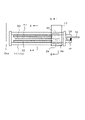
- a sheet-like material 100 as shown in FIG. 1
- a plurality of tabs 101 protruding in the width direction are formed in the longitudinal direction at a predetermined interval in the edge portion 100b extending from the sheet body 100a in the width direction (horizontal direction in FIG. 1). It has a continuously arranged shape.
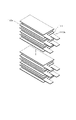
- Two types of single electrode film pieces 110a and 110b are cut out from such a sheet-like object 100 for each tab 101. Then, as shown in FIG.
- the single electrode films 110a and 110b are alternately laminated in a predetermined number while sandwiching the insulating film 111. Then, as shown in FIG. 3, the final laminated body is formed as a battery unit 200 having two electrode blocks 210a and 210b in which tabs 101 are laminated.
- the edge portion 100b on which the tabs 101 of the sheet-like material 100 are arranged does not exert tension due to transportation. Due to the flow of gas discharged from the discharge port and the flow of gas sucked through the intake port, the gas may flutter, bend, or be drawn into the intake port. As a result, normal dust removal cannot be performed on the surface of the edge portion 100b of the sheet-like material 100.
- the present invention has been made in view of such circumstances, and dust removal can normally remove dust from the surface of a sheet-like object having edge portions having a shape in which convex pieces are continuously arranged in the longitudinal direction at intervals. It provides the device.
- the dust removing device is provided with a discharge port and a suction port facing the surface of the sheet-like object to be conveyed and arranged at predetermined intervals in the transfer direction of the sheet-like object, and the sheet from the discharge port.
- a dust remover that sucks gas on the surface of the sheet-like object through the suction port while discharging gas to the surface of the object, and the discharge port is one in the width direction of the sheet-like object.
- the suction port includes a first discharge port for discharging gas to a portion other than the edge portion of the sheet, and a second discharge port for discharging gas to the edge portion of the sheet-like material.
- the gas discharged from the first discharge port is sprayed to the portion other than the edge portion of the sheet-like object, and the edge portion is formed.
- the gas discharged from the second discharge port is sprayed.
- the gas on the surface of the sheet-like material other than the edge portion is sucked through the first suction port, and the gas on the surface of the edge portion is sucked through the second suction port.
- the gas discharged from different discharge ports is sprayed to the edge portion of the sheet-like object and the other portions, and the gas on the surface of the edge portion of the sheet-like object and the other portions.
- the gas on the surface of the sheet is sucked through a different suction port, the gas is sprayed onto the edge portion of the sheet-like object with a strength suitable for the shape of the edge portion, which is different from the other portions.
- gas can be sucked from the surface of the edge portion of the sheet-like object with a strength suitable for the shape of the edge portion, which is different from that from the surface of the other portion.
- the dust removing device may be configured such that the supply path of the gas discharged from the first discharge port and the supply path of the gas discharged from the second discharge port are different.
- the gas supplied from different supply paths is discharged from the first discharge port and the second discharge port, and the gas is sprayed on the edge portion and the other portion of the sheet-like object, respectively.
- the gas can be easily blown onto the edge portion of the sheet-like object with a strength suitable for the form of the edge portion, which is different from the other portions.
- the opening area per unit length of the second discharge port can be smaller than the opening area per unit length of the first discharge port.
- the gas in the process of transporting the sheet-like material, the gas can be blown to the edge portion of the sheet-like material weaker than the other parts.
- the second discharge port may be configured to include a plurality of small holes arranged in a direction crossing the transport direction of the sheet-like material.
- the gas can be discharged weakly from the second discharge port as compared with the case where it extends like a slit.
- the dust removing device may have a gas discharge path having a shape that gradually expands from the opening facing the sheet-like object to be conveyed to the second discharge port.
- the gas is discharged from the second discharge port through the gas discharge path that gradually spreads from the opening.
- the discharge pressure of the gas discharged from the peripheral portion of the second discharge port along the inner peripheral wall of the gas discharge path from the opening is the portion facing the opening of the second discharge port without following the inner peripheral wall of the gas discharge path. It is smaller than the discharge pressure of the gas directly discharged from. As a result, it is possible to reduce the discharge pressure of the gas discharged from the peripheral portion of the second discharge port while maintaining the discharge pressure of the gas discharged from the portion of the second discharge port facing the opening at a desired pressure. ..
- the cross section perpendicular to the sheet-like object to which the gas discharge path is conveyed can be configured to have a shape that gradually expands in an arc shape.
- the gas is discharged from the peripheral portion of the second discharge port along the inner peripheral wall which gradually expands in the cross-sectional arc shape of the gas discharge path from the opening, and faces the opening of the second discharge port. Discharge directly from the part.
- the discharge pressure of the gas discharged from the peripheral portion of the second discharge port is maintained while maintaining the discharge pressure of the gas discharged from the portion of the second discharge port facing the opening at a desired pressure. Can be lowered.
- the second discharge port is arranged in a direction crossing the transport direction of the sheet-like material, and each includes a plurality of slits extending in a direction crossing the arrangement direction, and further, the plurality of slits.
- Each of the slits has a gas ejection path extending from the opening facing the sheet-like object to the slit, and the cross section of the gas ejection path perpendicular to the slit gradually expands from the opening to the slit. It can be configured to have a shape.
- the gas is discharged from a plurality of slits through the gas discharge path gradually expanding from the opening.
- the discharge pressure of the gas discharged from the upstream end in the transport direction of the sheet-like material to which the slit is conveyed along the inner peripheral wall of the gas discharge path from the opening does not follow the inner peripheral wall of the gas discharge path, and the discharge pressure of the gas is not along the inner peripheral wall of the gas discharge path. It is smaller than the discharge pressure of the gas directly discharged from the portion facing the opening. This makes it possible to reduce the discharge pressure of the gas discharged from the upstream end of each slit while maintaining the discharge pressure of the gas discharged from the portion of each slit facing the opening at a desired pressure.
- the edge portion of the sheet-like object to be conveyed enters the facing region of the upstream end portion of the plurality of slits, the edge portion of the sheet-like object is discrete from each of the plurality of slits. Gas with discharge pressure is sprayed. Therefore, when the edge portion of the sheet-like object enters the facing region of the upstream end portion of the plurality of slits in the transport direction, the discharged air may simultaneously act on the entire head portion of the edge portion. not. Therefore, in a state where air having a desired discharge pressure is discharged from the slit portion facing the opening, it is necessary to reliably prevent the edge portion from being turned up by the air acting on the edge portion of the sheet-like object. Can be done.
- the shape of the cross section can be configured to gradually expand in an arc shape.
- the gas is discharged from the upstream end in the transport direction of the sheet-like material to be transported by each slit along the inner peripheral wall that gradually expands in the cross-sectional arc shape of the gas discharge path from the opening.
- the gas is discharged directly from the portion of each slit facing the opening without following the inner peripheral wall of the gas discharge path.
- the discharge pressure of the gas discharged from the upstream end of each slit is lowered while maintaining the discharge pressure of the gas discharged from the portion of each slit facing the opening at a desired pressure. can do.
- each of the plurality of slits may be formed so as to be inclined diagonally with respect to the transport direction of the sheet-like material.
- gas is blown from a plurality of discretely arranged slits to a wider area of the edge portion of the sheet-like material, not simply a plurality of streaks. Can be done.
- each of the plurality of slits may be formed so as to overlap the adjacent slits when viewed in the transport direction of the sheet-like material.
- gas can be blown from a plurality of discretely arranged slits to the edge portion of the sheet-like object without a gap during the transfer of the sheet-like object.
- the plurality of slits may be arranged in parallel, or may be arranged in a zigzag manner in a direction crossing the transport direction of the sheet-like material.
- the opening area per unit length of the second suction port can be smaller than the opening area per unit length of the first suction port.
- the second suction port may be configured to include a plurality of small holes arranged in a direction crossing the transport direction of the sheet-like object.
- gas can be sucked weakly through the second suction port as compared with the case where it extends in a slit shape or in an elongated rectangular shape.
- the dust removing method is a dust removing method for removing dust from a sheet-like material having edge portions having a shape in which convex pieces are continuously arranged in the longitudinal direction at intervals, and is a conveyed sheet-like material.
- a dust remover having a discharge port and a suction port which are arranged facing the surface of the sheet and extend in a direction crossing the transfer direction at a predetermined interval in the transfer direction of the sheet-like material is used, and the sheet-like object is formed from the discharge port. It has an air flow generation step of sucking gas on the surface of the sheet-like object through the suction port while discharging gas to the surface of the object, and in the air flow generation step, the gas is discharged from the discharge port.
- the sheet-like material is weaker than the edge portion of the sheet-like material other than the edge portion, and the suction of gas through the suction port is performed by the edge portion of the sheet-like object.
- the structure is weaker from the surface of the edge portion than from the surface of the portion other than the above.
- the edge portion of the sheet-like material having a shape in which the convex pieces are continuously arranged in the transport direction at a certain interval has a portion other than that.
- the surface of the sheet-like material is dust-free by blowing the gas weaker and sucking the gas weaker from the surface of such an edge portion from the surface of the other portion.
- the dust removing device when gas is blown onto the surface of the sheet-like material to be conveyed and the gas on the surface is sucked to remove dust on the surface of the sheet-like material, the edge of the sheet-like material is removed.
- Gas can be sprayed onto the end portion with a strength suitable for the shape of the edge portion, which is different from the other portions, and from the surface of the edge portion of the sheet-like material, the other portion.
- the gas can be sucked in with a strength suitable for the shape of the edge portion, which is different from that on the surface of the above.
- the sheet-like material having the edge portions having a shape in which the convex pieces are continuously arranged in the longitudinal direction at a certain interval is conveyed in the longitudinal direction.
- the edge portion of the sheet-like object is sprayed with a weaker gas than the other portions, and from the surface of such an edge portion, the other portion is present. Gas is sucked weaker from the surface.
- FIG. 1 is a diagram showing an electrode film as an example of a sheet-like material to be dust-removed.
- FIG. 2 is a diagram showing a laminated state of a single electrode film piece cut out from the electrode film shown in FIG. 1.
- FIG. 3 is a diagram showing a battery unit formed by laminating a plurality of single electrode film pieces as shown in FIG.
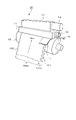
- FIG. 4 is a perspective view showing a dust removing device according to the first embodiment of the present invention.
- FIG. 5 is a side view showing the dust removing device according to the first embodiment of the present invention.
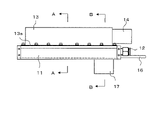
- FIG. 6 is a plan view showing a dust removing device according to the first embodiment of the present invention.
- FIG. 7 is a front view showing a dust removing device according to the first embodiment of the present invention.
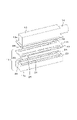
- FIG. 8 is an exploded perspective view (No. 1) showing the structure of the dust remover according to the first embodiment of the present invention.
- FIG. 9 is an exploded perspective view (No. 2) showing the structure of the dust remover according to the first embodiment of the present invention.
- FIG. 10 is a bottom view showing a dust removing device according to the first embodiment of the present invention.
- FIG. 11 is a cross-sectional view showing a cross section taken along line AA in FIGS. 6, 7, and 10 of the dust remover.
- FIG. 12 is a cross-sectional view showing a cross section taken along line BB in FIGS. 6, 7, and 10 of the dust remover.
- FIG. 13 is an enlarged view showing the relative positional relationship between the sheet-like object to be dust-removed and the discharge port and suction port of the dust-removing device.
- FIG. 14 is a side view showing a dust removing device according to a second embodiment of the present invention.
- FIG. 15 is a bottom view showing a dust removing device according to a second embodiment of the present invention.
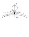
- FIG. 16 is a diagram showing a principle in which a sheet-like object (tab) is turned up by air discharged from a discharge port.
- FIG. 17 is a bottom view showing a dust removing device according to a third embodiment of the present invention.
- FIG. 18 is a partially cutaway bottom view showing a partially enlarged dust removing device according to a third embodiment of the present invention.
- FIG. 19 is a cross-sectional view showing a cross section taken along line AA in FIG. 18 of the dust remover.
- FIG. 20 is an enlarged cross-sectional view showing a gas discharge path leading to a second discharge port (slit).
- FIG. 21 is a diagram showing the discharge pressure of the air discharged from the second discharge port (slit).
- FIG. 22 is a bottom view showing a modified example of the dust removing device according to the third embodiment.
- FIG. 23 is a bottom view showing another modification of the dust removing device according to the third embodiment.
- FIG. 24 is a diagram showing a modified example of the second discharge port.
- FIGS. 4 to 13 The dust removing device according to the first embodiment of the present invention is shown in FIGS. 4 to 13.
- 4 is a perspective view showing the dust removing device
- FIG. 5 is a side view showing the dust removing device
- FIG. 6 is a plan view showing the dust removing device
- FIG. 7 is a plan view showing the dust removing device.
- FIG. 8 and 9 are exploded perspective views showing the structure of the dust remover
- FIG. 10 is a bottom view showing the dust remover.
- FIG. 11 is a cross-sectional view showing a cross section taken along line AA in FIGS. 6, 7 and 10 of the dust remover
- FIG. 12 is a cross-sectional view showing the cross section of the dust remover in FIGS. 6, 7, and 10. It is sectional drawing which shows the B line cross section.
- FIG. 13 is an enlarged view showing the relative positional relationship between the sheet-like object to be dust-removed and the discharge port and suction port of the dust-removing device.
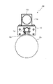
- the sheet-like object 100 to be dust-removed is wound around a transport roller 15 as a support portion, and in a state of being stretched with a certain tension applied, the length thereof is increased by the rotation of the transport roller 15. It is transported in the direction (transport direction Dcv).
- the sheet-like material 100 is, for example, an electrode film used for manufacturing a secondary battery, as in the above-mentioned example (see FIGS. 1 to 3), and has an edge portion extending in the width direction from the sheet body 100a.
- the shape of 100b is such that a plurality of tabs 101 (convex pieces) are continuously arranged in the longitudinal direction at predetermined intervals. No tension is applied to each tab 101 (edge end portion 100b) of the sheet-shaped object 10 transported by the transport roller 15.
- the dust removing device 10 is arranged so as to face the surface of the sheet-like object 100 wound around the transport roller 15 (see FIGS. 4 and 5). Further, as shown in FIGS. 6 and 7 together with FIGS. 4 and 5, the dust removing device 10 is orthogonal to the rotation axis direction of the transport roller 15 (the width direction of the sheet-shaped object 100 and the transport direction Dcv of the sheet-shaped object 100). It is provided with a long block-shaped dust removing head 11 extending in the direction in which the dust is removed (laterally in each of FIGS. 6 and 7), and an exhaust duct unit 13 extending along the upper surface of the dust removing head 11. The bottom of the exhaust duct unit 13 is open, and a flange 13a is formed at the opening edge portion thereof.
- the dust removal unit 11 and the exhaust duct unit 13 are integrated, and a space as an exhaust path is created inside the exhaust duct unit 13. It is formed.
- An exhaust port 14 is provided on the side surface of the exhaust duct unit 13. The exhaust port 14 is connected to a suction mechanism (for example, a vacuum pump: not shown), and by the operation of the suction mechanism, air passing through the exhaust path of the exhaust duct unit 13 is discharged to the outside through the exhaust port 14.
- a suction mechanism for example, a vacuum pump: not shown
- An air supply port 12 is provided on the side surface of the dust removal head 11.
- the air supply port 12 is connected to an air supply mechanism (for example, a pressure pump: not shown) that supplies pressurized air, and the operation of the air supply mechanism allows the pressurized air to be removed from the dust head 11 (for example, through the air supply port 12). It is taken into the air injection chamber 20) described later.
- the dust removing head 11 is provided with an air supply pipe 16 inserted from the side surface thereof.
- the air supply pipe 16 is also connected to an external air supply mechanism (not shown), and pressurized air is introduced by the operation of the air supply mechanism.
- the air supply mechanism connected to the air supply port 12 and the air supply mechanism connected to the air supply pipe 16 may be the same or different.
- the edge portion 100b on which the tab 101 of the sheet-like object 100 is formed is pressed toward the transport roller 15 (support portion) and guided along the transport roller 15.
- the guide plate 17 (seat holding mechanism) is fixed.
- the dust removing head 11 has a structure in which the head block 11a and the suction adjusting plate 11b are overlapped with each other.
- the head block 11a has an air injection chamber 20, a front first air suction chamber 21, a rear first air suction chamber 22, and a front second air suction chamber 23 as spaces opened at the joint surface with the suction adjustment plate 11b, respectively.
- the rear second air suction chamber 24 is formed.
- the air injection chamber 20 extends in the longitudinal direction at the central portion of the head block 11a in the width direction.
- the front side first air suction chamber 21 and the front side second air suction chamber 23 extending in the longitudinal direction of the head block 11a are along the front side edge of the head block 11a (corresponding to the upstream side of the transport direction Dcv of the sheet-like object 100). Arranged side by side.
- the rear first air suction chamber 22 and the rear second air suction chamber 24 extending in the longitudinal direction of the head block 11a are the rear edges of the head block 11a (corresponding to the downstream side of the sheet-shaped object 100 in the transport direction Dcv). Arranged side by side along.
- the front second air suction chamber 23 and the rear second air suction chamber 24 are shorter than the front first air suction chamber 21 and the rear first air suction chamber 22, respectively, and their lengths are the sheets to be dust-removed. It roughly corresponds to the width of the formed edge portion 100b (see FIG. 1) of the tab 101 of the object 100. Further, the lengths of the front first air suction chamber 21 and the rear first air suction chamber 22 substantially correspond to the width of the sheet body 100a (see FIG. 1) of the sheet-like material 100.
- the suction adjustment plate 11b has a front side first suction adjustment hole 25 and a rear side first suction adjustment hole 26, each of which is composed of a plurality of elongated holes, and a front side, each of which is composed of a plurality of small holes so as to penetrate the suction adjustment plate 11b.
- a second suction adjusting hole 27 and a rear second suction adjusting hole 28 are formed.
- the total opening area of the front second suction adjusting hole 27 and the rear second suction adjusting hole 28 is smaller than the total opening area of each of the front first suction adjusting hole 25 and the rear first suction adjusting hole 26.
- the head block 11a and the suction adjusting plate 11b are fixed to each other by a plurality of bolts together with the exhaust duct unit 13 (flange 13a) described above in a state of being overlapped with each other.
- the front first air suction chamber 21 of the head block 11a and the front first suction adjustment hole 25 of the suction adjustment plate 11b face each other, and the head The front second air suction chamber 23 of the block 11a and the front second suction adjustment hole 27 of the suction adjustment plate 11b face each other.
- the rear first air suction chamber 22 of the head block 11a and the rear first suction adjustment hole 26 of the suction adjustment plate 11b face each other, and the rear second air suction chamber 24 and the suction adjustment plate of the head block 11a face each other.
- the rear second suction adjusting hole 28 of 11b faces the rear side second suction adjusting hole 28. Then, the air injection chamber 20 of the head block 11a is closed by the suction adjustment plate 11b in a state where the head block 11a and the suction adjustment plate 11b are overlapped with each other.
- the surface of the dust removing head 11 (head block 11a) facing the transport roller 15 has a first slit-shaped slit extending in the longitudinal direction to the central portion in the width direction.
- the discharge port 30 is formed. Further, on the surface thereof, an elongated rectangular front first suction port 31 is formed along the front edge, and an elongated rectangular rear first suction port 32 is formed along the rear edge. ..
- the first discharge port 30 communicates with the air injection chamber 20 formed in the head block 11a, and is introduced from the air supply port 12 into the air injection chamber 20 (air supply path).
- the pressurized air to be generated is discharged from the first discharge port 30.
- the front first suction port 31 is a space (exhaust) in the exhaust duct unit 13 through the front first air suction chamber 21 formed in the head block 11a and the front first suction adjustment hole 25 formed in the suction adjustment plate 11b. It communicates with the route).
- the rear first suction port 32 is a space in the exhaust duct unit 13 through the rear first suction chamber 22 formed in the head block 11a and the rear first suction adjusting hole 26 formed in the suction adjusting plate 11b.
- the guide plate 17 fixed to the surface of the dust removing head 11 (head block 11a) facing the transport roller 15 is arranged in the longitudinal direction with the front first suction port 31 and is aligned with the front second suction port 31. 33 is formed.
- the front second suction port 33 is composed of a plurality of small holes arranged in a straight line, and the total opening area per unit length thereof is smaller than the opening area per unit length of the front first suction port 31.
- the guide plate 17 is formed with a rear second suction port 34 alongside the rear first suction port 32 in the longitudinal direction.
- the rear second suction port 34 is composed of a plurality of small holes arranged in a straight line, and the total opening area per unit length thereof is the rear first suction port 32. Is smaller than the opening area per unit length of.
- the front side second suction port 33 formed in the guide plate 17 has the front side second air suction chamber 23 formed in the head block 11a and the front side second suction port 33 formed in the suction adjustment plate 11b. It communicates with the space (exhaust path) in the exhaust duct unit 13 through the suction adjusting hole 27.
- the rear second suction port 34 formed in the guide plate 17 is a rear second suction adjusting hole 28 formed in the rear second air suction chamber 24 formed in the head block 11a and the suction adjusting plate 11b. It communicates with the space inside the exhaust duct unit 13 through.
- the front second suction port 33 and the rear second suction port 33 communicating with the space inside the exhaust duct unit 13 as the air passing through the space (exhaust path) of the exhaust duct unit 13 is discharged to the outside through the exhaust port 14. 2 Air is sucked through the suction port 34.
- the air supply pipe 16 is inserted into the head block 11a of the dust removing head 11, and its closed end reaches the vicinity of the edge of the guide plate 17.
- the guide plate 17 is formed with a second discharge port 35 at a predetermined position close to the front second suction port 33 between the front second suction port 33 and the rear second suction port 34 so as to be parallel to them.
- the second discharge port 35 is composed of a plurality of small holes arranged in a straight line, and the total opening area per unit length thereof is smaller than the opening area per unit length of the first discharge port 30.
- the second discharge port 35 formed in the guide plate 17 communicates with the air supply pipe 16 inserted into the head block 11a, and the pressurized air introduced into the air supply pipe 16 (another air supply path). Is discharged from the second discharge port 35.
- the dust removing device 10 having the above-mentioned structure removes dust from the sheet-like material 100 as follows.
- the sheet-like object 100 is conveyed in a state where the tension on the sheet body 100a is applied by the rotation of the conveying roller 15.
- the tabs 101 of the sheet-like object 100 are continuously arranged at the edges, as shown in FIG. 13, together with FIGS. 4 and 5.
- the portion 100b is guided along the transport roller 15 by the guide plate 17 and moves while being pushed toward the transport roller 15.
- the air injection chamber 20 and the second discharge which are the air supply paths to the first discharge port 30, are due to the difference in the opening area per unit length of the first discharge port 30 and the second discharge port 35. Due to the difference in shape of the air supply pipe 16 which is the air supply path to the outlet 35, the strength of the air discharge from the second discharge port 35 is smaller than the strength of the air discharge from the first discharge port 30. Further, the difference in the opening area per unit length of the front first suction port 31 and the rear first suction port 32, and the front second suction port 33 and the rear second suction port 34, and the suction adjustment plate 11b.
- Front side first suction adjustment hole 25 and rear side first suction adjustment hole 26, and front side second suction adjustment hole 27 and rear side second suction adjustment hole 28 due to the difference in opening area per unit length.
- the strength of air suction through each of the two suction ports 33 and the rear second suction port 34 is smaller than the strength of air suction through each of the front first suction port 31 and the rear first suction port 32.
- the air discharged relatively strongly from the first discharge port 30 of the dust remover 10 is blown to the surface of the sheet-like material 100 mainly on the surface of the sheet body 100a, and the front side first. Air on the surface of the sheet body 100a is relatively strongly sucked through each of the suction port 31 and the rear first suction port 32 (air flow generation step). Dust that has risen mainly from the surface of the seat body 100a due to the air from the first discharge port 30 is sucked together with the air through the front first suction port 31 and the rear suction port 32. As a result, mainly the surface of the sheet body 100a of the sheet-like object 100 is dust-removed.
- the edge portion 100b of the sheet-shaped object 100 which is pressed by the guide plate 17 toward the transport roller 15 and guided along the transport roller 15, is on the front side as shown in FIG. It moves while facing the second suction port 33, the second discharge port 35, and the rear second suction port 34.
- air discharged relatively weakly from the second discharge port 35 is blown onto the surface of the edge portion 100b of the sheet-like material 100, while the front side second suction port 33 and the rear side second suction port 34 are respectively. Air on the surface of the edge portion 100b of the sheet-like object 100 is relatively weakly sucked through the sheet (air flow generation step).
- the dust removing device 10 As described above, relatively strong suction of air discharged from the first discharge port 30 and relatively strong suction of air through the front side first suction port 31 and the rear side first suction port 32. As a result, mainly the sheet body 100a of the sheet-like object 100 can be reliably removed.
- the edge portion 100b of the sheet-like object 100 is different from the sheet body 100a, and the air has a strength suitable for the form of the edge portion 100b (the form in which the tabs 101 (convex pieces) are arranged).
- Discharge and suction specifically, relatively weak air is discharged from the second discharge port 35, and relatively weak air is sucked through the front second suction port 33 and the rear second suction port 34. ..
- two suction ports front side first suction port 31 and rear side first suction port 32 are provided with the first discharge port 30 interposed therebetween. Not limited to this, only one of the suction ports may be provided. Further, in that case, either one of the front side second suction port 33 and the rear side second suction port 34 may be provided.
- the shapes of the second discharge port 35, the front second suction port 33, and the rear second suction port 34 are not limited to those described above, and may be arranged in a non-parallel manner, for example. Further, each of them may be composed of a single hole, a plurality of small holes arranged so as to be scattered, and the like.
- the guide plate 17 was provided, but the guide plate 17 can be omitted. In this case, for example, it is configured like the dust removing device according to the second embodiment below.
- the dust removing device according to the second embodiment of the present invention is configured as shown in FIGS. 14 and 15.
- the guide plate 17 is omitted, and the second discharge port 35 composed of a plurality of small holes arranged in a straight line is directly formed on the air supply pipe 16.
- the first embodiment is carried out at the point where the surface is formed and the surface of the air supply pipe 16 on which the second discharge port 35 is formed is exposed from the surface of the head block 11a of the dust removing head 11 facing the transport roller 15. It is different from the dust remover according to the form (see FIG. 4-FIG. 13).
- the air discharged relatively strongly from the first discharge port 30 and the front side first suction port 31 and the rear side first suction port 32 are passed through. Due to the relatively strong suction of the air, it is possible to reliably remove dust mainly from the sheet body 100a of the sheet-like object 100.
- the edge portion 100b of the sheet-like object 100 is different from the sheet body 100a, and the air has a strength suitable for the form of the edge portion 100b (the form in which the tabs 101 (convex pieces) are arranged).
- Discharge and suction specifically, discharge of relatively weak air from the second discharge port 35 formed in the portion exposed from the surface of the head block 11a of the air supply pipe 16, and formed on the surface of the head block 11a.
- a relatively weak suction of air is performed through the front second suction port 33 and the rear second suction port 34.
- the tab 101 in the edge portion 100b of the sheet-like object 100 can normally remove dust from the edge portion 100b of the sheet-like object 100 without fluttering, bending, or being drawn into the suction port. can.
- the air supply pipe 16 can rotate about the extending direction in the state of being inserted into the head block 11a. By rotating the air supply pipe 16, the direction of the air discharged from the second suction port 35 can be adjusted. By this adjustment, air can be blown from the direction more suitable for normal dust removal to the edge portion 100b (continuous tab 101) of the sheet-like object 100.
- the static pressure in the region along the flow decreases due to the high-speed flow of air discharged from the discharge port O (opening) of the dust remover 10 (see the thick arrow in FIG. 16), resulting in a negative pressure.
- BA can occur (Bernoulli effect).
- a negative pressure BA is generated in the region along the flow of the discharged air in this way, when the tab 101 of the edge portion 100b of the sheet-like material 100 transported by the transport roller 15 enters the region facing the discharge port O.
- the negative pressure BA raises the tip portion of the tab 101.
- the tip portion of the tab 101 rises even slightly in this way, the air discharged into the gap enters the tab 101, and the tab 101 is turned up at once. As a result, it is not possible to properly remove dust from the edge portion 100b (tab 101) of the sheet-like object 100.
- the tab 101 (edge end portion 100b) of the sheet-like material 100 conveyed by the negative pressure state caused by the Bernoulli effect described above is provided. It is designed to prevent it from turning over.
- the dust removing device 10 according to the third embodiment of the present invention is configured as shown in FIGS. 17-19.
- 17 is a bottom view showing the dust remover
- FIG. 18 is a partially cutaway bottom view showing the dust remover partially enlarged
- FIG. 19 is a line AA in FIG. 18 of the dust remover.
- the dust remover according to the third embodiment is different from the dust remover according to the first embodiment (see FIGS. 4 to 13) in that the second discharge port 40 is composed of a plurality of slits 40a.
- the structure for supplying high-pressure air to the plurality of slits 40a of the second discharge port 40 and the structure for fixing the guide plate 17 to the dust removing head 11 are different from those of the dust removing device according to the first embodiment.
- the dust removing device 10 (FIG. 10) according to the first embodiment is on the surface of the dust removing head 11 (head block 11a) facing the transport roller 15 (sheet-like object 100 (tab 101)).
- a first discharge port 30 extending in the longitudinal direction, a front side first suction port 31 and a rear side first suction port 32 are formed, respectively.
- the dust removing head 11 (head block 11a) is provided with a first air supply port 12a and a second air supply port 12b.
- the high-pressure air introduced into the dust removing head 11 (head block 11a) via the first air supply port 12a is the first discharge port 30 as in the dust removing device 10 (see FIG. 11) according to the first embodiment. Discharge from.
- a second discharge port 40 composed of a plurality of slits 40a is first on the surface of the dust removing head 11 (head block 11a) facing the transport roller 15. It is formed so as to line up in the extending direction of the discharge port 30.
- the plurality of slits 40a constituting the second discharge port 40 are arranged at predetermined intervals in the longitudinal direction of the dust removing head 11 in the direction crossing the transport direction Dcv of the sheet-shaped object 100 (the direction orthogonal to the transport direction Dcv). Orthogonal.
- each of the plurality of slits 40a extends in a direction crossing the arrangement direction (longitudinal direction of the dust removing head 11 which is the width direction of the sheet-like object 100) and is inclined obliquely with respect to the transport direction Dcv of the sheet-like object 100. ing.
- the air supply passage 41 directs the inside of the dust removing head 11 (head block 11a) toward each of the plurality of slits 40a of the second discharge port 40. Is extending. Then, the high-pressure air introduced from the second air supply port 12b passes through the supply air passage 41 and is discharged from each of the plurality of slits 40a of the second discharge port 40 (details will be described later).
- a guide plate 17 is fixed to the dust removing head 11 by a fixing block 18.
- the guide plate 17 presses the tab 101 (edge end portion 100b) of the sheet-shaped object 100 conveyed by the rotating transfer roller 15 toward the transfer roller 15 and guides the sheet-like object 100 along the transfer roller 15.
- the front side second suction port 33 composed of a plurality of small holes communicates with the exhaust duct unit 13 through the front side second air suction chamber 23 and the front side suction adjustment hole 27 of the dust removal head 11.
- the rear second suction port 34 composed of a plurality of small holes communicates with the exhaust duct unit 13 through the rear second air suction chamber 24 and the rear suction adjustment hole 28 of the dust removing head 11.
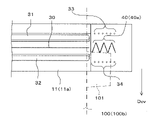
- each of the plurality of slits 40a constituting the second discharge port 40 communicates with the air supply passage 41.
- the connecting path 42a extending from the supply air passage 41 is connected to the gas discharge path 42b leading to the slit 40a through the opening 43.
- the cross section perpendicular to the slit 40a of the gas discharge path 42b gradually expands from the opening 43 to the slit 40a, specifically, in an arc shape. It becomes a shape.
- the air discharged relatively strongly from the first discharge port 30 and the front first suction port 31 The relatively strong suction of air through the first suction port 32 on the rear side makes it possible to reliably remove dust mainly from the sheet body 100a of the sheet-like object 100.
- the edge portion 100b (tab 101) of the sheet-like object 100 passes through the air discharged from the plurality of slits 40a of the second discharge port 40 and the front side second suction port 33 and the rear side second suction port 34. Dust is removed by suctioning the air.
- the high-pressure air passing from the supply air passage 41 to the connecting passage 42a is discharged from the slit 40a through the gas discharge passage 42b gradually expanding from the opening 43.
- the discharge pressure of the air discharged from the slit 40a is distributed as shown in FIG. That is, the discharge pressure Pe1 of the air discharged from the upstream end in the transport direction Dcv of the sheet-like material 100 (tab 101) transported from the opening 43 along the inner peripheral wall of the gas discharge path 42b by the slit 40a is gas discharge. It is smaller than the discharge pressure Pc of the air directly discharged from the portion of the slit 40a facing the opening 43 without following the inner peripheral wall of the road 42b.
- the air pressure Pc discharged from the portion of the slit 40a facing the opening 43 is maintained at a desired pressure (smaller than the discharge pressure from the first discharge port 30), and is discharged from the upstream end of the slit 40a.
- the air discharge pressure Pe1 becomes low.
- the discharge pressure Pe1 of the air discharged from the upstream end of the slit 40a becomes low, so that a negative pressure state due to the Bernoulli effect is less likely to occur in the facing region Eb of the upstream end of the slit 40a. .. Therefore, when the tab 101 of the sheet-shaped object 100 to be conveyed enters the facing region Eb at the upstream end of the slit 40a, it is prevented from being turned up by the negative pressure state that may occur due to the Bernoulli effect. The dust adhering to the tab 101 is surely removed by the air having a desired discharge pressure Pc discharged from the portion of the slit 40a facing the opening 43.
- the discharge pressure Pe2 (see FIG. 21) of the air discharged from the downstream end of the slit 40a is also low, and the tab 101 of the sheet-like material 100 to be conveyed faces the downstream end of the slit 40a. You can escape from the area in a stable state without fluttering.
- the tab 101 of the sheet-like object 100 to be conveyed enters the facing region Eb at the upstream end of the plurality of slits 40a
- the tab 101 is removed from each of the plurality of slits 40a.
- Air with a certain discharge pressure Pe1 is blown discretely. Therefore, when the tab 101 of the sheet-like object 100 enters the facing region Eb of the upstream end portion of the plurality of slits 40a, the discharged air does not act simultaneously on the entire head portion of the tab 101. Therefore, in a state where air having a desired discharge pressure Pc is discharged from the portion of the slit 40a facing the opening 43, it is possible to reliably prevent the tab 101 from being turned up by the air acting on the leading portion of the tab 101. can.
- each slit 40a constituting the second discharge port 40 is inclined obliquely with respect to the transport direction Dcv of the sheet-like object 100 (tab 101)
- the facing region of each slit 40a is set to the tab 101 of the sheet-like object 100. As it passes, gas can be blown over a wider area of the tab 101 from the discretely arranged slits 40a.
- the arrangement mode of the plurality of slits 40a constituting the second discharge port 40 is not limited to that described above (see FIGS. 17 and 18).
- a plurality of slits 40a are zigzag in the width direction of the sheet-like object 100 (tab 101) to be conveyed, that is, in the direction crossing the transfer direction of the sheet-like object 100 (orthogonal direction). It may be arranged.
- each of the plurality of slits 40a constituting the second discharge port 40 is formed so as to overlap the adjacent slits 40a in the transport direction Dcv of the sheet-like material 100 (tab 101). You can also do it.
- gas can be blown onto the sheet-shaped object 100 (tab 101) without gaps from the plurality of slits 40a arranged discretely. As a result, the surface of the sheet-like material 100 (tab 101) can be more reliably removed from dust.
- a second discharge port is formed as an elongated hole 45 extending in a direction (for example, a direction orthogonal to each other) across the transport direction Dcv of the sheet-shaped object 100 (tab 101), that is, in the width direction of the dust removing head 11.
- the connecting path 46a extending from the air supply path 41 is connected to the gas discharge path 46b reaching the elongated hole 45 through the opening 47.
- the cross section of the gas discharge path 46b perpendicular to the elongated hole 45 (shown by a broken line in FIG. 24) has a shape that gradually expands from the opening 47 to the elongated hole 45, specifically, similarly to the above-mentioned one (see FIG. 20). Has a shape that gradually expands in an arc shape.
- the elongated hole 45 is conveyed from the opening 47 along the inner peripheral wall of the gas discharge path 46b in the same manner as described above.
- the discharge pressure of the air discharged from the upstream end portion EG1 in the transport direction Dcv of 100 (tab 101) is the air discharged directly from the portion facing the opening 47 of the elongated hole 45 without following the inner peripheral wall of the gas discharge path 46b. It is smaller than the discharge pressure of.
- the upstream end portion EG1 of the elongated hole 45 is used.
- the discharge pressure of the discharged air can be lowered.
- the discharge pressure of the gas discharged from the upstream end portion EG1 of the elongated hole 45 (second discharge port) is lowered, so that the facing region of the upstream end portion EG1 of the elongated hole 45 is similarly as described above.
- the negative pressure state due to the Bernoulli effect is less likely to occur. Therefore, it is possible to prevent the tab 101 of the sheet-shaped object 100 to be transported from being turned up due to the negative pressure state that may occur due to the Bernoulli effect when entering the facing region Eb of the upstream end portion EG1 of the elongated hole 45.
- the second discharge port is composed of the elongated hole 45 as shown in FIG. 24, unlike the case where the second discharge port 40 is composed of a plurality of slits 40a (see FIGS. 17 to 20), the transport is carried out.
- the tab 101 of the sheet-like object 100 to be formed enters the facing region Eb of the upstream end portion EG1 of the elongated hole 45, the air discharged from the elongated hole 45 acts on the entire head portion of the tab 101 at the same time. Therefore, in consideration of this, it is necessary to adjust the discharge pressure of the air discharged from the elongated hole 45 (the discharge pressure of the gas from the opening 47).
- the support portion that supports the sheet-like object 100 is not limited to the transfer rollers 15 and 55, and the transfer roller 15 may be a flat surface as long as the sheet-like object 100 to be conveyed is in contact with the support portion.
- 55 may be a curved surface other than a cylindrical curved surface.
- the dust removing measure 100 is arranged so as to face the surface portion of the sheet-like object 100 that is not particularly supported by the support portion, even if it is not arranged so as to face the support portion that supports the sheet-like object 100. It may be one.
- the sheet-like material to be dust-removed may be a sheet-like material unwound from the roll or a single-leaf sheet-like material.
- the sheet-like material to be dust-removed may be a thin and wide material that can be affected by the air flow through the discharge port and the suction port, and is not limited to the so-called sheet-like material.
- the film-like one such as the electrode film used for manufacturing the above-mentioned secondary battery, or the film-like one may be used.
- the dust removing device and the dust removing method according to the present invention have the effect that the surface of a sheet-like object having edge portions having a shape in which convex pieces (tabs) are continuously arranged in the longitudinal direction at certain intervals can be normally removed.
- a dust removing device and a dust removing method for removing dust on the surface of the sheet-like material by sucking the gas on the surface of the sheet-like material while discharging gas to the surface of the sheet-like material to be conveyed It is useful.
- Dust removal device 11 Dust removal head 11a Head block 11b Suction adjustment plate 12 Air supply port 12a First air supply port 12b Second intake port 13 Exhaust duct unit 13a Flange 14 Exhaust port 15 Conveyor roller 16 Air supply pipe 17 Guide plate 18 Guide fixing block 20 Air injection chamber 21 Front 1st air suction chamber 22 Rear 1st air suction chamber 23 Front 2nd air suction chamber 24 Rear 2nd air suction chamber 25 Front 1st suction adjustment hole 26 Rear 1st suction adjustment hole 27 Front 2nd suction adjustment hole 28 Rear 2nd suction adjustment hole 30 1st discharge port 31 Front 1st suction port 32 Rear 1st suction port 33 Front 2nd suction port 34 Rear 2nd suction port 35 2nd discharge port 40 Second discharge port 40a Slit 41 Air supply path 42a, 46a Connection path 42b, 46b Gas discharge path 43, 47 Opening 45 Elongated hole 100 Sheet-like object 100a Sheet body 100b Edge end 101 tab (convex piece)
Landscapes
- Engineering & Computer Science (AREA)
- Mechanical Engineering (AREA)
- Manufacturing & Machinery (AREA)
- Chemical & Material Sciences (AREA)
- Chemical Kinetics & Catalysis (AREA)
- Electrochemistry (AREA)
- General Chemical & Material Sciences (AREA)
- Cleaning In General (AREA)
- Registering, Tensioning, Guiding Webs, And Rollers Therefor (AREA)
- Advancing Webs (AREA)
Abstract
Description
11 除塵ヘッド
11a ヘッドブロック
11b 吸引調整プレート
12 給気ポート
12a 第1給気ポート
12b 第2吸気ポート
13 排気ダクトユニット
13a フランジ
14 排気ポート
15 搬送ローラ
16 給気管
17 ガイド板
18 ガイド固定ブロック
20 エア噴射室
21 前側第1エア吸引室
22 後側第1エア吸引室
23 前側第2エア吸引室
24 後側第2エア吸引室
25 前側第1吸引調整孔
26 後側第1吸引調整孔
27 前側第2吸引調整孔
28 後側第2吸引調整孔
30 第1吐出口
31 前側第1吸引口
32 後側第1吸引口
33 前側第2吸引口
34 後側第2吸引口
35 第2吐出口
40 第2吐出口
40a スリット
41 給気路
42a、46a 連結路
42b,46b 気体吐出路
43、47 開口
45 細長孔
100 シート状物
100a シート本体
100b 縁端部分
101 タブ(凸片部)
Claims (16)
- 搬送されるシート状物の表面に対向し、該シート状物の搬送方向に所定の間隔をもって配列された吐出口と吸引口とを備え、
前記吐出口から前記シート状物の表面に対して気体を吐出しつつ、前記吸引口を通して前記シート状物の表面上の気体を吸引する、除塵装置であって、
前記吐出口は、
前記シート状物の幅方向における一方の縁端部分以外の部分に対して気体を吐出する第1吐出口と、
前記シート状物の前記縁端部分に対して気体を吐出する第2吐出口と、を含み、
前記吸引口は、
前記シート状物の前記縁端部分以外の部分の表面上の気体を吸引する第1吸引口と、
前記シート状物の前記縁端部分の表面上の気体を吸引する第2吸引口と、を含む、
除塵装置。 - 前記第1吐出口から吐出される気体の供給経路と第2吐出口から吐出される気体の供給経路とが異なる、請求項1記載の除塵装置。
- 前記第2吐出口の単位長当たりの開口面積は、前記第1吐出口の単位長当たりの開口面積より小さい、請求項1または2記載の除塵装置。
- 前記第2吐出口は、前記シート状物の搬送方向を横切る方向に並ぶ複数の小孔を含む、請求項3記載の除塵装置。
- 搬送される前記シート状物に対向する開口から前記第2吐出口まで徐々に広がる形状の気体吐出路を有する、請求項1または2記載の除塵装置。
- 前記気体吐出路の搬送される前記シート状物に垂直な断面は、円弧状に徐々に広がる形状を有する、請求項5記載の除塵装置。
- 前記第2吐出口は、前記シート状物の搬送方向を横切る方向に配列され、それぞれがその配列方向を横切る方向に延びる複数のスリットを含み、
更に、前記複数のスリットのそれぞれに対して設けられ、前記シート状物に対向する開口からスリットまで延びる気体噴出路を有し、
前記気体噴出路の前記スリットに垂直な断面は、前記開口から前記スリットまで徐々に広がる形状を有する、請求項1または2記載の除塵装置。 - 前記断面の形状は、円弧状に徐々に広がる形状である、請求項7記載の除塵装置。
- 前記複数のスリットのそれぞれは、前記シート状物の搬送方向に対して斜めに傾いて形成された、請求項7または8記載の除塵装置。
- 前記複数のスリットのそれぞれは、前記シート状物の搬送方向に見て隣接するスリットに重なった状態で形成された、請求項9記載の除塵装置。
- 前記複数のスリットは、平行に配置された、請求項7乃至10のいずれかに記載の除塵装置。
- 前記複数のスリットは、前記シート状物の搬送方向を横切る方向においてジグザグに配列さされた、請求項7乃至10のいずれかに記載の除塵装置。
- 前記第2吸引口の単位長当たりの開口面積は、前記第1吸引口の単位長当たりの開口面積より小さい、請求項1乃至12のいずれかに記載の除塵装置。
- 前記第2吸引口は、前記シート状物の搬送方向を横切る方向に並ぶ複数の小孔を含む、請求項13記載の除塵装置。
- 凸片部がある間隔をもって長手方向に連続して配列された形状の縁端部分を有するシート状物の除塵を行う除塵方法であって、
搬送されるシート状物の表面に対向して配置され、該シート状物の搬送方向に所定の間隔をもって該搬送方向を横切る方向に延びる吐出口と吸引口とを備えた除塵装置を用い、
前記吐出口から前記シート状物の表面に対して気体を吐出しつつ、前記吸引口を通して前記シート状物の表面上の気体を吸引する気流発生工程を有し、
前記気流発生工程において、
前記吐出口からの気体の吐出は、前記シート状物の前記縁端部分以外の部分に対するより、前記シート状物の前記縁端部分に対するほうが弱いとともに、
前記吸引口を通した気体の吸引は、前記シート状物の前記縁端部分以外の部分の表面上からより、前記縁端部分の表面上からのほうが弱い、除塵方法。 - 前記吐出口が、前記シート状物の前記縁端部分以外に対して気体を吐出する第1吐出口と、前記シート状物の前記縁端部分に対して気体を吐出する第2吐出口と、を含み、
前記吸引口が、
前記シート状物の前記縁端部分以外の部分の表面上の気体を吸引する第1吸引口と、前記シート状物の前記縁端部分の表面上の気体を吸引する第2吸引口と、を含む前記除塵装置を用い、
前記気流発生工程において、
前記第2吐出口からの気体の吐出を、前記第1吐出口からの気体の吐出より弱くするとともに、
前記第2吸引口による気体の吸引を、前記第1吸引口による気体の吸引より弱くする、請求項15記載の除塵方法。
Priority Applications (4)
| Application Number | Priority Date | Filing Date | Title |
|---|---|---|---|
| KR1020237003364A KR102946758B1 (ko) | 2020-03-10 | 2021-08-20 | 제진 장치 및 제진 방법 |
| US18/247,317 US12396602B2 (en) | 2020-03-10 | 2021-08-20 | Dust removal device and dust removal method |
| CN202180066558.8A CN116323021B (zh) | 2020-03-10 | 2021-08-20 | 除尘装置和除尘方法 |
| EP21874966.1A EP4223426A4 (en) | 2020-03-10 | 2021-08-20 | DUST COLLECTION DEVICE AND DUST COLLECTION METHOD |
Applications Claiming Priority (3)
| Application Number | Priority Date | Filing Date | Title |
|---|---|---|---|
| JP2020040637 | 2020-03-10 | ||
| JP2020-164827 | 2020-09-30 | ||
| JP2020164827A JP7347809B2 (ja) | 2020-03-10 | 2020-09-30 | 除塵装置及び除塵方法 |
Publications (1)
| Publication Number | Publication Date |
|---|---|
| WO2022070663A1 true WO2022070663A1 (ja) | 2022-04-07 |
Family
ID=77766742
Family Applications (1)
| Application Number | Title | Priority Date | Filing Date |
|---|---|---|---|
| PCT/JP2021/030511 Ceased WO2022070663A1 (ja) | 2020-03-10 | 2021-08-20 | 除塵装置及び除塵方法 |
Country Status (6)
| Country | Link |
|---|---|
| US (1) | US12396602B2 (ja) |
| EP (1) | EP4223426A4 (ja) |
| JP (1) | JP7347809B2 (ja) |
| KR (1) | KR102946758B1 (ja) |
| CN (1) | CN116323021B (ja) |
| WO (1) | WO2022070663A1 (ja) |
Cited By (1)
| Publication number | Priority date | Publication date | Assignee | Title |
|---|---|---|---|---|
| CN116274162A (zh) * | 2023-03-16 | 2023-06-23 | 江苏风驰碳基新材料研究院有限公司 | 一种电池极片加工线的除尘装置 |
Families Citing this family (3)
| Publication number | Priority date | Publication date | Assignee | Title |
|---|---|---|---|---|
| JP7574968B1 (ja) * | 2023-03-07 | 2024-10-29 | 東レ株式会社 | シート状物の異物除去装置、シート状物の製造装置およびシート状物の製造方法 |
| CN222587515U (zh) * | 2024-03-08 | 2025-03-11 | 无锡先导智能装备股份有限公司 | 除尘装置和切叠一体机 |
| WO2025254961A2 (en) * | 2024-06-07 | 2025-12-11 | Illinois Tool Works Inc. | Air intake manifold with adjustable shutters |
Citations (10)
| Publication number | Priority date | Publication date | Assignee | Title |
|---|---|---|---|---|
| JPH03276480A (ja) * | 1990-03-26 | 1991-12-06 | Fuji Photo Film Co Ltd | フロッピーディスクのクリーニング装置 |
| JPH05138136A (ja) | 1991-11-12 | 1993-06-01 | Toray Ind Inc | シート状物用除塵装置 |
| JP2003229404A (ja) * | 2001-11-12 | 2003-08-15 | Tokyo Electron Ltd | 基板処理装置 |
| JP2004009047A (ja) * | 2002-06-07 | 2004-01-15 | Yuji Kurata | エア・クリーナ装置のクリーナヘッド |
| JP2004041851A (ja) * | 2002-07-09 | 2004-02-12 | Hugle Electronics Inc | 除塵ヘッド |
| JP2011200830A (ja) * | 2010-03-26 | 2011-10-13 | Mitsuboshi Diamond Industrial Co Ltd | エア集塵装置 |
| JP2014100622A (ja) * | 2012-11-16 | 2014-06-05 | Nitto Kogyo:Kk | 除塵装置 |
| JP2015213860A (ja) * | 2014-05-08 | 2015-12-03 | 東洋熱工業株式会社 | 異物除去装置 |
| JP2017150808A (ja) * | 2017-03-24 | 2017-08-31 | アイエス ジャパン株式会社 | エアブルーム、スプレードライヤの乾燥室及びスプレークーラの冷却室 |
| CN109226092A (zh) * | 2018-09-10 | 2019-01-18 | 中国建材国际工程集团有限公司 | 一种静电收尘装置 |
Family Cites Families (15)
| Publication number | Priority date | Publication date | Assignee | Title |
|---|---|---|---|---|
| US3420710A (en) * | 1964-09-03 | 1969-01-07 | Du Pont | Process and apparatus for cleaning webs utilizing a sonic air blast |
| JPH07138136A (ja) | 1993-11-22 | 1995-05-30 | Kao Corp | 毛髪用洗浄剤組成物 |
| DE19519544C2 (de) * | 1995-05-27 | 1999-08-19 | Sundwig Gmbh | Vorrichtung zum Entfernen von Flüssigkeit von der Oberfläche eines Bandes |
| US5596783A (en) * | 1995-06-07 | 1997-01-28 | Electrostatics, Inc. | Sheet and web cleaner with face plate on suction hood |
| US5614264A (en) * | 1995-08-11 | 1997-03-25 | Atotech Usa, Inc. | Fluid delivery apparatus and method |
| US6941606B2 (en) * | 2002-07-02 | 2005-09-13 | Electrostatics, Incorporated | Sheet and web cleaner on suction hood |
| US6921438B2 (en) * | 2002-07-30 | 2005-07-26 | John Lausevic | Vacuum cleaner attachment for fungi removal and method of use thereof |
| JP4152871B2 (ja) * | 2003-12-03 | 2008-09-17 | 東京エレクトロン株式会社 | ノズル及び基板処理装置 |
| US7111797B2 (en) * | 2004-03-22 | 2006-09-26 | International Business Machines Corporation | Non-contact fluid particle cleaner and method |
| GB2463394B8 (en) * | 2004-10-22 | 2013-08-14 | Predictive Maintenance Company | Web cleaner |
| KR200437869Y1 (ko) * | 2006-12-04 | 2008-01-04 | 씨티에스(주) | 제진노즐 내의 공기토출구 구조 |
| JP6058312B2 (ja) * | 2012-08-06 | 2017-01-11 | ヒューグル開発株式会社 | クリーニングヘッド |
| JP6975953B2 (ja) * | 2016-12-28 | 2021-12-01 | ヒューグル開発株式会社 | 異物除去装置及び異物除去方法 |
| KR101894037B1 (ko) * | 2018-03-16 | 2018-09-04 | 에스제이이 주식회사 | 컨베이어 벨트 크리닝 장치 |
| JP2021142450A (ja) * | 2020-03-10 | 2021-09-24 | ヒューグル開発株式会社 | 除塵装置及び除塵方法 |
-
2020
- 2020-09-30 JP JP2020164827A patent/JP7347809B2/ja active Active
-
2021
- 2021-08-20 EP EP21874966.1A patent/EP4223426A4/en active Pending
- 2021-08-20 CN CN202180066558.8A patent/CN116323021B/zh active Active
- 2021-08-20 WO PCT/JP2021/030511 patent/WO2022070663A1/ja not_active Ceased
- 2021-08-20 US US18/247,317 patent/US12396602B2/en active Active
- 2021-08-20 KR KR1020237003364A patent/KR102946758B1/ko active Active
Patent Citations (10)
| Publication number | Priority date | Publication date | Assignee | Title |
|---|---|---|---|---|
| JPH03276480A (ja) * | 1990-03-26 | 1991-12-06 | Fuji Photo Film Co Ltd | フロッピーディスクのクリーニング装置 |
| JPH05138136A (ja) | 1991-11-12 | 1993-06-01 | Toray Ind Inc | シート状物用除塵装置 |
| JP2003229404A (ja) * | 2001-11-12 | 2003-08-15 | Tokyo Electron Ltd | 基板処理装置 |
| JP2004009047A (ja) * | 2002-06-07 | 2004-01-15 | Yuji Kurata | エア・クリーナ装置のクリーナヘッド |
| JP2004041851A (ja) * | 2002-07-09 | 2004-02-12 | Hugle Electronics Inc | 除塵ヘッド |
| JP2011200830A (ja) * | 2010-03-26 | 2011-10-13 | Mitsuboshi Diamond Industrial Co Ltd | エア集塵装置 |
| JP2014100622A (ja) * | 2012-11-16 | 2014-06-05 | Nitto Kogyo:Kk | 除塵装置 |
| JP2015213860A (ja) * | 2014-05-08 | 2015-12-03 | 東洋熱工業株式会社 | 異物除去装置 |
| JP2017150808A (ja) * | 2017-03-24 | 2017-08-31 | アイエス ジャパン株式会社 | エアブルーム、スプレードライヤの乾燥室及びスプレークーラの冷却室 |
| CN109226092A (zh) * | 2018-09-10 | 2019-01-18 | 中国建材国际工程集团有限公司 | 一种静电收尘装置 |
Non-Patent Citations (1)
| Title |
|---|
| See also references of EP4223426A4 |
Cited By (1)
| Publication number | Priority date | Publication date | Assignee | Title |
|---|---|---|---|---|
| CN116274162A (zh) * | 2023-03-16 | 2023-06-23 | 江苏风驰碳基新材料研究院有限公司 | 一种电池极片加工线的除尘装置 |
Also Published As
| Publication number | Publication date |
|---|---|
| CN116323021B (zh) | 2025-10-03 |
| CN116323021A (zh) | 2023-06-23 |
| EP4223426A1 (en) | 2023-08-09 |
| EP4223426A4 (en) | 2024-11-13 |
| JP2021142517A (ja) | 2021-09-24 |
| KR20230031335A (ko) | 2023-03-07 |
| US20230380644A1 (en) | 2023-11-30 |
| KR102946758B1 (ko) | 2026-03-31 |
| US12396602B2 (en) | 2025-08-26 |
| JP7347809B2 (ja) | 2023-09-20 |
Similar Documents
| Publication | Publication Date | Title |
|---|---|---|
| WO2022070663A1 (ja) | 除塵装置及び除塵方法 | |
| CN107073526A (zh) | 异物的除去方法以及异物的除去装置 | |
| CA2482167A1 (en) | Device for processing stacks of electrostatically chargeable flat items | |
| JP2015213860A (ja) | 異物除去装置 | |
| US6899327B2 (en) | Sheet guide apparatus | |
| CN108274906A (zh) | 薄片体输送装置及具备该薄片体输送装置的图像形成装置 | |
| JP2014101159A (ja) | 搬送装置 | |
| JP2021142450A (ja) | 除塵装置及び除塵方法 | |
| JP3703803B2 (ja) | 加工機械内でウェブ材料または枚葉紙材料を浮遊させながらガイドするための装置 | |
| JPH11115157A (ja) | プリント機械に供給される被プリント物をクリーニングする装置を備えているプリント装置 | |
| JP2004167494A (ja) | 枚葉ワークの異物除去装置 | |
| US6941606B2 (en) | Sheet and web cleaner on suction hood | |
| JP7098179B2 (ja) | 除塵装置 | |
| US20240359931A1 (en) | Image forming system | |
| WO2022264670A1 (ja) | 粉塵除去装置 | |
| JP2002518273A (ja) | ウェブ搬送システム | |
| JP4736276B2 (ja) | インクジェット記録装置 | |
| KR102923251B1 (ko) | 흡입 및 토출식 분진 제거장치 | |
| JPH09141170A (ja) | 塗布装置 | |
| JPH033848A (ja) | 空気吹出箱 | |
| JP7673368B2 (ja) | シート搬送装置 | |
| US20240399768A1 (en) | Drying apparatus | |
| JP2024125086A (ja) | シート製品の製造方法 | |
| JP2025127712A (ja) | シート搬送装置 | |
| JP2005212984A (ja) | 紙葉類搬送装置 |
Legal Events
| Date | Code | Title | Description |
|---|---|---|---|
| 121 | Ep: the epo has been informed by wipo that ep was designated in this application |
Ref document number: 21874966 Country of ref document: EP Kind code of ref document: A1 |
|
| ENP | Entry into the national phase |
Ref document number: 20237003364 Country of ref document: KR Kind code of ref document: A |
|
| WWE | Wipo information: entry into national phase |
Ref document number: 18247317 Country of ref document: US |
|
| NENP | Non-entry into the national phase |
Ref country code: DE |
|
| ENP | Entry into the national phase |
Ref document number: 2021874966 Country of ref document: EP Effective date: 20230502 |
|
| WWG | Wipo information: grant in national office |
Ref document number: 18247317 Country of ref document: US |
|
| WWG | Wipo information: grant in national office |
Ref document number: 202180066558.8 Country of ref document: CN |