WO2022070891A1 - 非水電解質二次電池用正極および非水電解質二次電池 - Google Patents
非水電解質二次電池用正極および非水電解質二次電池 Download PDFInfo
- Publication number
- WO2022070891A1 WO2022070891A1 PCT/JP2021/033786 JP2021033786W WO2022070891A1 WO 2022070891 A1 WO2022070891 A1 WO 2022070891A1 JP 2021033786 W JP2021033786 W JP 2021033786W WO 2022070891 A1 WO2022070891 A1 WO 2022070891A1
- Authority
- WO
- WIPO (PCT)
- Prior art keywords
- positive electrode
- electrolyte secondary
- aqueous electrolyte
- secondary battery
- mixture layer
- Prior art date
- Legal status (The legal status is an assumption and is not a legal conclusion. Google has not performed a legal analysis and makes no representation as to the accuracy of the status listed.)
- Ceased
Links
Images
Classifications
-
- H—ELECTRICITY
- H01—ELECTRIC ELEMENTS
- H01M—PROCESSES OR MEANS, e.g. BATTERIES, FOR THE DIRECT CONVERSION OF CHEMICAL ENERGY INTO ELECTRICAL ENERGY
- H01M4/00—Electrodes
- H01M4/02—Electrodes composed of, or comprising, active material
- H01M4/13—Electrodes for accumulators with non-aqueous electrolyte, e.g. for lithium-accumulators; Processes of manufacture thereof
- H01M4/131—Electrodes based on mixed oxides or hydroxides, or on mixtures of oxides or hydroxides, e.g. LiCoOx
-
- H—ELECTRICITY
- H01—ELECTRIC ELEMENTS
- H01M—PROCESSES OR MEANS, e.g. BATTERIES, FOR THE DIRECT CONVERSION OF CHEMICAL ENERGY INTO ELECTRICAL ENERGY
- H01M10/00—Secondary cells; Manufacture thereof
- H01M10/05—Accumulators with non-aqueous electrolyte
- H01M10/052—Li-accumulators
-
- H—ELECTRICITY
- H01—ELECTRIC ELEMENTS
- H01M—PROCESSES OR MEANS, e.g. BATTERIES, FOR THE DIRECT CONVERSION OF CHEMICAL ENERGY INTO ELECTRICAL ENERGY
- H01M10/00—Secondary cells; Manufacture thereof
- H01M10/05—Accumulators with non-aqueous electrolyte
- H01M10/052—Li-accumulators
- H01M10/0525—Rocking-chair batteries, i.e. batteries with lithium insertion or intercalation in both electrodes; Lithium-ion batteries
-
- H—ELECTRICITY
- H01—ELECTRIC ELEMENTS
- H01M—PROCESSES OR MEANS, e.g. BATTERIES, FOR THE DIRECT CONVERSION OF CHEMICAL ENERGY INTO ELECTRICAL ENERGY
- H01M4/00—Electrodes
- H01M4/02—Electrodes composed of, or comprising, active material
- H01M4/04—Processes of manufacture in general
- H01M4/0402—Methods of deposition of the material
- H01M4/0404—Methods of deposition of the material by coating on electrode collectors
-
- H—ELECTRICITY
- H01—ELECTRIC ELEMENTS
- H01M—PROCESSES OR MEANS, e.g. BATTERIES, FOR THE DIRECT CONVERSION OF CHEMICAL ENERGY INTO ELECTRICAL ENERGY
- H01M4/00—Electrodes
- H01M4/02—Electrodes composed of, or comprising, active material
- H01M4/13—Electrodes for accumulators with non-aqueous electrolyte, e.g. for lithium-accumulators; Processes of manufacture thereof
-
- H—ELECTRICITY
- H01—ELECTRIC ELEMENTS
- H01M—PROCESSES OR MEANS, e.g. BATTERIES, FOR THE DIRECT CONVERSION OF CHEMICAL ENERGY INTO ELECTRICAL ENERGY
- H01M4/00—Electrodes
- H01M4/02—Electrodes composed of, or comprising, active material
- H01M4/13—Electrodes for accumulators with non-aqueous electrolyte, e.g. for lithium-accumulators; Processes of manufacture thereof
- H01M4/139—Processes of manufacture
- H01M4/1391—Processes of manufacture of electrodes based on mixed oxides or hydroxides, or on mixtures of oxides or hydroxides, e.g. LiCoOx
-
- H—ELECTRICITY
- H01—ELECTRIC ELEMENTS
- H01M—PROCESSES OR MEANS, e.g. BATTERIES, FOR THE DIRECT CONVERSION OF CHEMICAL ENERGY INTO ELECTRICAL ENERGY
- H01M4/00—Electrodes
- H01M4/02—Electrodes composed of, or comprising, active material
- H01M4/36—Selection of substances as active materials, active masses, active liquids
-
- H—ELECTRICITY
- H01—ELECTRIC ELEMENTS
- H01M—PROCESSES OR MEANS, e.g. BATTERIES, FOR THE DIRECT CONVERSION OF CHEMICAL ENERGY INTO ELECTRICAL ENERGY
- H01M4/00—Electrodes
- H01M4/02—Electrodes composed of, or comprising, active material
- H01M4/36—Selection of substances as active materials, active masses, active liquids
- H01M4/48—Selection of substances as active materials, active masses, active liquids of inorganic oxides or hydroxides
- H01M4/50—Selection of substances as active materials, active masses, active liquids of inorganic oxides or hydroxides of manganese
- H01M4/505—Selection of substances as active materials, active masses, active liquids of inorganic oxides or hydroxides of manganese of mixed oxides or hydroxides containing manganese for inserting or intercalating light metals, e.g. LiMn2O4 or LiMn2OxFy
-
- H—ELECTRICITY
- H01—ELECTRIC ELEMENTS
- H01M—PROCESSES OR MEANS, e.g. BATTERIES, FOR THE DIRECT CONVERSION OF CHEMICAL ENERGY INTO ELECTRICAL ENERGY
- H01M4/00—Electrodes
- H01M4/02—Electrodes composed of, or comprising, active material
- H01M4/36—Selection of substances as active materials, active masses, active liquids
- H01M4/48—Selection of substances as active materials, active masses, active liquids of inorganic oxides or hydroxides
- H01M4/52—Selection of substances as active materials, active masses, active liquids of inorganic oxides or hydroxides of nickel, cobalt or iron
- H01M4/525—Selection of substances as active materials, active masses, active liquids of inorganic oxides or hydroxides of nickel, cobalt or iron of mixed oxides or hydroxides containing iron, cobalt or nickel for inserting or intercalating light metals, e.g. LiNiO2, LiCoO2 or LiCoOxFy
-
- H—ELECTRICITY
- H01—ELECTRIC ELEMENTS
- H01M—PROCESSES OR MEANS, e.g. BATTERIES, FOR THE DIRECT CONVERSION OF CHEMICAL ENERGY INTO ELECTRICAL ENERGY
- H01M4/00—Electrodes
- H01M4/02—Electrodes composed of, or comprising, active material
- H01M4/62—Selection of inactive substances as ingredients for active masses, e.g. binders, fillers
-
- H—ELECTRICITY
- H01—ELECTRIC ELEMENTS
- H01M—PROCESSES OR MEANS, e.g. BATTERIES, FOR THE DIRECT CONVERSION OF CHEMICAL ENERGY INTO ELECTRICAL ENERGY
- H01M4/00—Electrodes
- H01M4/02—Electrodes composed of, or comprising, active material
- H01M4/62—Selection of inactive substances as ingredients for active masses, e.g. binders, fillers
- H01M4/621—Binders
- H01M4/622—Binders being polymers
-
- H—ELECTRICITY
- H01—ELECTRIC ELEMENTS
- H01M—PROCESSES OR MEANS, e.g. BATTERIES, FOR THE DIRECT CONVERSION OF CHEMICAL ENERGY INTO ELECTRICAL ENERGY
- H01M4/00—Electrodes
- H01M4/02—Electrodes composed of, or comprising, active material
- H01M4/62—Selection of inactive substances as ingredients for active masses, e.g. binders, fillers
- H01M4/621—Binders
- H01M4/622—Binders being polymers
- H01M4/623—Binders being polymers fluorinated polymers
-
- H—ELECTRICITY
- H01—ELECTRIC ELEMENTS
- H01M—PROCESSES OR MEANS, e.g. BATTERIES, FOR THE DIRECT CONVERSION OF CHEMICAL ENERGY INTO ELECTRICAL ENERGY
- H01M4/00—Electrodes
- H01M4/02—Electrodes composed of, or comprising, active material
- H01M4/62—Selection of inactive substances as ingredients for active masses, e.g. binders, fillers
- H01M4/624—Electric conductive fillers
- H01M4/625—Carbon or graphite
-
- H—ELECTRICITY
- H01—ELECTRIC ELEMENTS
- H01M—PROCESSES OR MEANS, e.g. BATTERIES, FOR THE DIRECT CONVERSION OF CHEMICAL ENERGY INTO ELECTRICAL ENERGY
- H01M4/00—Electrodes
- H01M4/02—Electrodes composed of, or comprising, active material
- H01M2004/021—Physical characteristics, e.g. porosity, surface area
-
- H—ELECTRICITY
- H01—ELECTRIC ELEMENTS
- H01M—PROCESSES OR MEANS, e.g. BATTERIES, FOR THE DIRECT CONVERSION OF CHEMICAL ENERGY INTO ELECTRICAL ENERGY
- H01M4/00—Electrodes
- H01M4/02—Electrodes composed of, or comprising, active material
- H01M2004/026—Electrodes composed of, or comprising, active material characterised by the polarity
- H01M2004/028—Positive electrodes
-
- Y—GENERAL TAGGING OF NEW TECHNOLOGICAL DEVELOPMENTS; GENERAL TAGGING OF CROSS-SECTIONAL TECHNOLOGIES SPANNING OVER SEVERAL SECTIONS OF THE IPC; TECHNICAL SUBJECTS COVERED BY FORMER USPC CROSS-REFERENCE ART COLLECTIONS [XRACs] AND DIGESTS
- Y02—TECHNOLOGIES OR APPLICATIONS FOR MITIGATION OR ADAPTATION AGAINST CLIMATE CHANGE
- Y02E—REDUCTION OF GREENHOUSE GAS [GHG] EMISSIONS, RELATED TO ENERGY GENERATION, TRANSMISSION OR DISTRIBUTION
- Y02E60/00—Enabling technologies; Technologies with a potential or indirect contribution to GHG emissions mitigation
- Y02E60/10—Energy storage using batteries
Definitions
- the present disclosure relates to a positive electrode for a non-aqueous electrolyte secondary battery and a non-aqueous electrolyte secondary battery.
- Non-aqueous electrolyte secondary batteries represented by lithium ion secondary batteries are used as a power source for electronic devices such as mobile terminals and as a power source for vehicles such as electric vehicles.
- the positive electrode can be obtained, for example, by applying a positive electrode slurry containing a positive electrode mixture such as a positive electrode active material to the surface of a positive electrode current collector sheet, drying the coating film, rolling it, and forming a positive electrode mixture layer.
- a positive electrode active material for example, a composite oxide containing lithium and nickel having a layered rock salt type crystal structure is used.
- the amount of the positive electrode slurry applied to the positive electrode current collector sheet is effective to increase the amount of the positive electrode slurry applied to the positive electrode current collector sheet and increase the thickness of the positive electrode mixture layer.
- the positive electrode and the negative electrode are wound via a separator to form an electrode group, the number of times the positive electrode is wound is reduced by increasing the thickness of the positive electrode mixture layer, and the separator and the positive electrode current collecting sheet that do not contribute to the capacity are reduced.
- the amount of the active material can be increased by that amount (for example, Non-Patent Document 1).
- one aspect of the present disclosure includes a positive electrode current collector sheet and a positive electrode mixture layer supported on the positive electrode current collector sheet, and the positive electrode mixture layer includes a positive electrode active material and a binder.
- the positive electrode active material contains a conductive agent
- the positive electrode active material has a layered rock salt type crystal structure, and contains a composite oxide containing lithium and an element A other than the lithium, and the element A contains at least nickel.
- the atomic ratio of the nickel to the element A: Ni / A is 0.8 or more and 1.0 or less
- the binder contains a polymer binder having a three-dimensional network structure, and the positive electrode current collector sheet.
- the weight of the positive electrode mixture layer supported per 1 m 2 of the above is 280 g or more, which relates to a positive electrode for a non-aqueous electrolyte secondary battery.
- a non-aqueous electrolyte secondary battery which comprises a positive electrode, a negative electrode, and a non-aqueous electrolyte, wherein the positive electrode is the positive electrode.
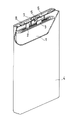
- FIG. 1 is a schematic perspective view in which a part of the non-aqueous electrolyte secondary battery according to the embodiment of the present disclosure is cut out.
- the positive electrode for a non-aqueous electrolyte secondary battery includes a positive electrode current collector sheet and a positive electrode mixture layer supported on the positive electrode current collector sheet, and the positive electrode mixture layer is a positive electrode active material. , A binder, and a conductive agent.
- the positive electrode active material contains a nickel-based composite oxide. That is, the composite oxide has a layered rock salt type crystal structure and contains lithium (Li) and an element A other than Li, and the element A contains at least nickel (Ni) and is an atom of Ni with respect to the element A. Ratio: Ni / A is 0.8 or more and 1.0 or less.
- the binder includes a polymer binder having a three-dimensional network structure (hereinafter, also referred to as binder P).
- the positive electrode mixture layer has a large thickness. That is, the mass of the positive electrode mixture layer supported per 1 m 2 of the positive electrode current collector sheet is 280 g or more.
- a nickel-based composite oxide having a Ni / A of 0.8 or more is used as the positive electrode active material, and the amount of the positive electrode mixture layer supported per 1 m 2 of the positive electrode current collector sheet is 280 g or more, and the thickness of the positive electrode mixture layer is increased. As a result, the rated capacity of the battery can be increased to a high capacity that could not be achieved in the past.
- the distribution state of the conductive agent coexisting with the binder is improved, and the electron conduction path is advanced in the positive electrode mixture layer. It is considered that the three-dimensional structure is developed and the internal resistance of the positive electrode mixture layer is reduced.
- the improvement in the distribution of the conductive agent is due to the fact that the polymer binder having a three-dimensional network structure adheres the composite oxide particles and the conductive agent to each other in the positive electrode mixture layer with excellent binding force. Conceivable. Further, since the adhesion between the positive electrode mixture layer and the positive electrode current collector sheet is improved, the resistance to stress due to expansion and contraction of the positive electrode active material during charging and discharging is also improved.
- the increase in DCR of the battery is suppressed, and the cycle characteristics and the like are improved.
- the effect of suppressing the increase in DCR when the amount of the positive electrode mixture layer supported is large is specifically obtained when the polymer binder has a three-dimensional network structure.
- the polymer binder has a three-dimensional network structure.
- the above-mentioned suppression of increase in DCR is insufficient.
- the binder P can be formed, for example, by cross-linking a polymer that functions as a binder.
- a known method such as addition of a crosslink agent, heating, irradiation with ultraviolet rays or an electron beam can be used.
- the binder P contains a fluorine-containing polymer and the fluorine-containing polymer is crosslinked. That is, it is preferable that the three-dimensional network structure is formed by cross-linking the fluorine-containing polymer having a binding force.
- the fluorine-containing polymer may contain at least one selected from the group consisting of units derived from vinylidene fluoride (VDF), units derived from propylene hexafluoride (HFP) and units derived from tetrafluoroethylene (TFE). .. In this case, the fluorine-containing polymer itself has excellent binding properties. Above all, from the viewpoint of electrochemical stability and stability of the positive electrode slurry, the fluorine-containing polymer preferably contains at least a unit derived from VDF.
- the fluorine-containing polymer preferably contains at least one selected from the group consisting of copolymers containing polyvinylidene fluoride (PVDF) and units derived from vinylidene fluoride (VDF).
- the copolymer may be a block copolymer or a random copolymer.
- the copolymer containing a unit derived from VDF may contain a copolymer of VDF and a fluorine-containing monomer other than VDF (hereinafter, referred to as monomer F). That is, the copolymer may contain a unit derived from VDF and a unit derived from the monomer F.
- the monomer F may contain at least one selected from the group consisting of HFP, TFE, ethylene trifluoride and ethylene trifluoride. Above all, HFP is preferable as the monomer F from the viewpoint of ensuring the flexibility of the positive electrode plate.
- the molar ratio (monomer F / VDF) of the unit derived from monomer F to the unit derived from VDF may be, for example, 0.01 or more and 0.5 or less, and may be 0.05. As mentioned above, it may be 0.3 or less.
- the fluorine-containing polymer may be crosslinked with a crosslinkable monomer (crosslinking agent).
- a crosslinkable monomer crosslinking agent
- the fluorine-containing polymer may undergo a dehydration condensation reaction with the crosslinkable monomer to form an amide bond or an ester bond, and the fluorine-containing polymer may be crosslinked via the crosslinkable monomer.
- the crosslinkable monomer may have a functional group (for example, a hydroxy group, a carboxy group, an amino group, etc.) that contributes to the condensation reaction.
- crosslinkable monomer examples include trimethylhexamethylenediamine, benzoyl peroxide, dicumyl peroxide, bisphenol A, hexamethylenediamine, ethylenediamine, isopropylethylenediamine, naphthalenediamine, 2,4,4-trimethyl-1 or 6 -Hexamethylenediamine and the like can be mentioned.
- the fluorine-containing polymer may have a functional group (for example, a hydroxy group, a carboxy group, an amino group, etc.) that contributes to the dehydration condensation reaction with the crosslinkable monomer, and the functional group is introduced into the fluorine-containing polymer. You may.
- a fluorine-containing polymer into which a carboxy group has been introduced and a crosslinkable monomer having two amino groups are subjected to a dehydration condensation reaction, and the fluorine-containing polymer is crosslinked via the crosslinkable monomer by an amide bond. May be good.
- the average molecular weight of the fluorine-containing polymer (for example, PVDF, PVDF-HFP) used together with the above-mentioned cross-linking agent is, for example, 100,000 or more and 2,000,000 or less.
- the above average molecular weight is a number average molecular weight (polystyrene equivalent value) obtained by gel permeation chromatography (GPC).
- the binder contains at least the binder P.
- the ratio of the binder P to the entire binder is, for example, 50% by mass or more, and all of the binders may be the binder P.
- the binder may contain a small amount of components other than the binder P.
- a resin material having no three-dimensional network structure for example, fluororesin, polyolefin resin, acrylic resin, etc.
- Specific examples include polytetrafluoroethylene (PTFE), polyvinylidene fluoride (PVDF), polyethylene, polypropylene, polyacrylic acid, methyl polyacrylic acid, and ethylene-acrylic acid copolymers.
- PTFE polytetrafluoroethylene
- PVDF polyvinylidene fluoride
- polyethylene polypropylene
- polyacrylic acid methyl polyacrylic acid
- ethylene-acrylic acid copolymers ethylene-acrylic acid copolymers
- the content of the binder in the positive electrode mixture layer is preferably, for example, 0.5 parts by mass or more and 2 parts by mass or less per 100 parts by mass of the positive electrode active material. In this case, it is easy to obtain the effect of suppressing the increase in DCR when the amount of the positive electrode mixture layer supported is large while increasing the capacity. Further, the binding force of the positive electrode mixture layer and the adhesion between the positive electrode mixture layer and the positive electrode current collector sheet are also likely to be improved. In this case, all of the binders may be binders P.
- the amount of the positive electrode mixture layer supported per 1 m 2 of the positive electrode current collector sheet may be 280 g or more and 400 g or less, or 280 g or more and 360 g or less. ..
- the thickness of the positive electrode mixture layer is, for example, 50 ⁇ m or more and 250 ⁇ m or less.
- the density of the positive electrode mixture layer may be 3.45 g / cm 3 or more and 3.75 g / cm 3 or less, or 3.5 g / cm 3 or more and 3.75 g / cm 3 or less.
- the density of the positive electrode mixture layer is 3.45 g / cm 3 or more, the number of contact points between the composite oxide and the conductive agent and the binder increases. In addition, contact points between the composite oxide particles are easily formed sufficiently. As a result, an electron conduction path is sufficiently formed, and a high capacity can be easily obtained. Further, the binding force of the positive electrode mixture layer and the adhesion between the positive electrode mixture layer and the positive electrode current collector sheet are also likely to be improved. Further, in the above case, it is advantageous in terms of improving the energy density of a cylindrical battery or the like, and it is effective when a wound electrode group is formed by using a longer electrode plate.
- the density of the positive electrode mixture layer is 3.75 g / cm 3 or less, the increase in strain in the positive electrode mixture layer due to expansion and contraction of the composite oxide during charging and discharging is suppressed, and the positive electrode mixture layer and the positive electrode collection are suppressed.
- the stress generated between the electric sheets is easily reduced, and the deterioration of the adhesion between the positive electrode mixture layer and the positive electrode current collecting sheet is easily suppressed.
- the composite oxide easily comes into contact with the non-aqueous electrolyte in the positive electrode mixture layer, and the increase in reaction resistance is suppressed.
- the voids are appropriately secured in the positive electrode mixture layer, the diffusion resistance to the non-aqueous electrolyte (movement of lithium ions) is sufficiently reduced even when the charge rate is high, and a high discharge capacity can be easily obtained.
- the positive electrode active material contains at least the above-mentioned nickel-based composite oxide.
- the atomic ratio Ni / A of the nickel-based composite oxide is 0.8 or more, the ratio of Ni to the element A is large, and the capacity tends to be increased.
- the ratio of the nickel-based composite oxide to the entire positive electrode active material is, for example, 80% by mass or more, and all of the positive electrode active materials may be nickel-based composite oxides.
- the positive electrode active material may contain a small amount of a composite oxide other than the nickel-based composite oxide (for example, LiCoO 2 , Li 2 NiO 2 , Li 5 FeO 4 , etc.).
- the element A contains at least Ni, and further contains cobalt (Co), manganese (Mn), aluminum (Al), magnesium (Mg), calcium (Ca), iron (Fe), copper (Cu), and zinc (Zn). , Chromium (Cr), Tungsten (Ti), Niob (Nb), Zirconium (Zr), Vanadium (V), Tantal (Ta), Molybdenum (Mo), Tungsten (W), Strontium (Sr) and Silicon (Si) , At least one selected from the group consisting of boron (B).
- the element A preferably contains Ni and at least one selected from the group consisting of Co, Mn and Al, and more preferably contains Ni, Co, Mn and / or Al. preferable.
- the element A contains Co, the phase transition of the composite oxide containing Li and Ni is suppressed during charging and discharging, the stability of the crystal structure is improved, and the cycle characteristics are likely to be improved.
- the element A contains Mn and / or Al, the thermal stability is improved.
- the nickel-based composite oxide is preferably an oxide represented by the general formula: Lia Ni x Coy M 1-x-y O 2 .
- M is Mn, Al, B, W, Sr, Mg, Mo. It is preferably at least one selected from the group consisting of Nb, Ti, Si and Zr.
- a which indicates the composition ratio of Li
- x which indicates the composition ratio of Ni
- y may be more than 0 and 0.2 or less.
- the nickel-based composite oxide contains Co
- the element M is Al, and 0 ⁇ y ⁇ 0.2 and 0 ⁇ (1-x ⁇ y) ⁇ 0.05 may be satisfied.
- the nickel-based composite oxide contains Al, the thermal stability of the composite oxide is likely to be improved. The value of a changes during charging and discharging.
- the particles of the composite oxide usually include secondary particles in which a plurality of primary particles are aggregated.
- the average particle size (D50) of the secondary particles is, for example, 5 ⁇ m or more and 20 ⁇ m or less.
- the average particle size (D50) here refers to the median diameter at which the volume integrated value is 50% in the volume-based particle size distribution.
- the average particle size (D50) of the secondary particles can be determined by measuring the particle size distribution by a laser diffraction method.
- the conductive agent By containing the conductive agent in the positive electrode mixture layer, a conductive path is sufficiently formed between the positive electrode active materials and between the positive electrode active material and the positive electrode current collector sheet.
- the conductive agent preferably contains carbon nanotubes (CNTs). The CNT is easily entangled with the polymer binder having a three-dimensional network structure, and the contact point between the CNT and the composite oxide is firmly maintained by the polymer binder during charging and discharging.
- the average length of CNT is preferably 0.5 ⁇ m or more, more preferably 0.5 ⁇ m or more and 10.0 ⁇ m or less, and further preferably 0.5 ⁇ m or more and 5.0 ⁇ m or less.
- the CNT is more likely to be entangled with the polymer binder having a three-dimensional network structure, and the contact point between the CNT and the composite oxide is easily maintained by the polymer binder during charging and discharging.
- CNTs are likely to intervene between the composite oxide particles, and the CNTs are likely to sufficiently form an electron conduction path between the composite oxide particles.
- the average diameter of CNTs may be 0.5 nm or more and 30 nm or less, and may be 0.5 nm or more and 20 nm or less.
- the average diameter of CNTs is 0.5 nm or more, the strength of CNTs is sufficiently secured, and the electron conduction path is easily maintained by CNTs during charging and discharging.
- CNTs are likely to intervene between the composite oxide particles.
- a cross section of the positive electrode mixture layer or an image of CNTs is obtained using a scanning electron microscope (SEM) or a transmission electron microscope (TEM), and a plurality of CNTs (for example, for example) are obtained using the images.
- SEM scanning electron microscope
- TEM transmission electron microscope
- CNTs (about 50 to 200) are arbitrarily selected, the length and diameter are measured, and the CNTs are averaged and obtained.
- the length of CNT refers to the length when it is linear.
- the conductive agent may contain a conductive material other than CNT.
- the conductive material other than CNT include graphite such as natural graphite and artificial graphite; carbon black such as acetylene black; metal fiber; and metal powder such as aluminum.
- the conductive agent one type may be used alone, or two or more types may be used in combination.
- the content of the conductive agent in the positive electrode mixture layer is preferably, for example, 0.01 part by mass or more and 1.0 part by mass or less per 100 parts by mass of the positive electrode active material. In this case, it is easy for the conductive agent to sufficiently form an electron conduction path between the positive electrode active material particles while increasing the capacity. In this case, all of the conductive agents may be CNTs.
- the positive electrode current collector sheet for example, a non-perforated conductive substrate (metal foil, etc.) or a porous conductive substrate (mesh body, net body, punching sheet, etc.) is used.
- the material of the positive electrode current collector sheet include stainless steel, aluminum, aluminum alloy, and titanium.
- the thickness of the positive electrode current collector sheet is, for example, 3 to 50 ⁇ m.
- the method for manufacturing a positive electrode is, for example, a step of preparing a positive electrode slurry by dispersing a positive electrode mixture containing a positive electrode active material, a binder and a conductive agent in a dispersion medium, and applying the positive electrode slurry to the surface of a positive electrode current collecting sheet and drying it.
- the step of forming a positive electrode mixture layer is included.
- the dried coating film may be rolled if necessary.
- the positive electrode mixture layer may be formed on one surface of the positive electrode current collector sheet, or may be formed on both surfaces.
- the dispersion medium for example, water, alcohol such as ethanol, N-methyl-2-pyrrolidone (NMP) and the like are used.
- Non-water electrolyte secondary battery One embodiment of the present disclosure comprises a positive electrode, a negative electrode, and a non-aqueous electrolyte.
- the positive electrode the above-mentioned positive electrode for a non-aqueous electrolyte secondary battery is used.
- the negative electrode includes, for example, a negative electrode current collector sheet and a negative electrode mixture layer supported on the negative electrode current collector sheet.
- the negative electrode is obtained, for example, by applying a negative electrode slurry in which a negative electrode mixture is dispersed in a dispersion medium to the surface of a negative electrode current collector sheet and drying the negative electrode mixture to form a negative electrode mixture layer. The dried coating film may be rolled if necessary.
- the negative electrode mixture layer may be formed on one surface of the negative electrode current collector sheet, or may be formed on both surfaces.
- the negative electrode mixture contains a negative electrode active material as an essential component, and may contain a binder, a conductive agent, a thickener and the like as optional components.
- binder a component other than the above-mentioned binder P, a rubber material such as styrene-butadiene rubber, or the like can be used.
- dispersion medium those exemplified for the positive electrode can be used.
- conductive agent those exemplified for the positive electrode can be used except for graphite.
- thickener for example, carboxymethyl cellulose (CMC) and a modified product thereof (including salts such as Na salt) and the like can be used.
- Examples of the negative electrode active material include carbon materials, silicon, silicon-containing materials, lithium alloys, and the like.
- the negative electrode active material preferably contains silicon and at least one Si-based active material of the silicon-containing material.
- the silicon-containing material for example, a composite material including a silicate phase containing at least one of an alkali metal element and a group 2 element and silicon particles dispersed in the silicate phase can be used. In this case, the initial charge / discharge efficiency and cycle characteristics are improved.
- the composite material comprises, for example, a lithium silicate phase and silicon particles dispersed in the lithium silicate phase.
- the lithium silicate phase may have, for example, a composition represented by Li 2u SiO u + 2 (0 ⁇ u ⁇ 2).
- SiO z (0.5 ⁇ z ⁇ 1.5) including the SiO 2 phase and the silicon particles dispersed in the SiO 2 phase may be used.
- the surface of the particles of the silicon-containing material may be covered with a conductive layer containing a conductive material such as a carbon material.
- the carbon material examples include graphite, easily graphitized carbon (soft carbon), and non-graphitized carbon (hard carbon). Of these, graphite, which has excellent charge / discharge stability and has a small irreversible capacity, is preferable.
- the graphite means a material having a graphite-type crystal structure, and includes, for example, natural graphite, artificial graphite, graphitized mesophase carbon particles, and the like. As the carbon material, one type may be used alone, or two or more types may be used in combination.
- the ratio of the Si-based active material to the total of the Si-based active material and the carbon material is, for example, preferably 0.5% by mass or more, more preferably 1% by mass or more. More preferably, it is 2% by mass or more. Further, from the viewpoint of improving the cycle characteristics, the ratio of the Si-based active material to the total of the Si-based active material and the carbon material is, for example, preferably 30% by mass or less, more preferably 20% by mass or less. , More preferably 15% by mass or less.
- the negative electrode current collector sheet for example, a conductive substrate exemplified by the positive electrode can be used.
- the material of the negative electrode current collecting sheet include stainless steel, nickel, nickel alloy, copper, and copper alloy.
- the thickness of the negative electrode current collector sheet is, for example, 1 to 50 ⁇ m.
- the non-aqueous electrolyte contains a non-aqueous solvent and a lithium salt dissolved in the non-aqueous solvent.
- cyclic carbonate ester for example, cyclic carbonate ester, chain carbonate ester, cyclic carboxylic acid ester, chain carboxylic acid ester and the like are used.
- cyclic carbonic acid ester examples include propylene carbonate (PC) and ethylene carbonate (EC).
- Cyclic carbonate having an unsaturated bond such as vinylene carbonate (VC) may be used.
- Cyclic carbonate having a fluorine atom such as fluoroethylene carbonate (FEC) may be used.
- chain carbonate ester include diethyl carbonate (DEC), ethyl methyl carbonate (EMC), dimethyl carbonate (DMC) and the like.
- Examples of the cyclic carboxylic acid ester include ⁇ -butyrolactone (GBL) and ⁇ -valerolactone (GVL).
- Examples of the chain carboxylic acid ester include methyl formate, ethyl formate, propyl formate, methyl acetate, ethyl acetate, propyl acetate, methyl propionate, ethyl propionate, propyl propionate and the like.
- the non-aqueous solvent one type may be used alone, or two or more types may be used in combination.
- lithium salt examples include LiClO 4 , LiBF 4 , LiPF 6 , LiAlCl 4 , LiSbF 6 , LiSCN, LiCF 3 SO 3 , LiCF 3 CO 2 , LiAsF 6 , LiB 10 Cl 10 , LiB 10 Cl 10, and LiCl. , LiBr, LiI, borates, imide salts and the like.
- borates include bis (1,2-benzenediolate (2-) -O, O') lithium borate and bis (2,3-naphthalenedioleate (2-) -O, O') boric acid.
- imide salts include bisfluorosulfonylimide lithium (LiN (FSO 2 ) 2 ), bistrifluoromethanesulfonate imide lithium (LiN (CF 3 SO 2 ) 2 ), and trifluoromethanesulfonate nonafluorobutane sulfonate imide lithium (LiN).
- lithium salt one kind may be used alone, or two or more kinds may be used in combination.
- concentration of the lithium salt in the non-aqueous electrolyte is, for example, 0.5 mol / L or more and 2 mol / L or less.
- the separator has high ion permeability and has moderate mechanical strength and insulation.
- a microporous thin film, a woven fabric, a non-woven fabric or the like can be used.
- polyolefins such as polypropylene and polyethylene are preferable.
- Non-aqueous electrolyte secondary battery is a group of electrodes in which a positive electrode and a negative electrode are wound via a separator, and a structure in which a non-aqueous electrolyte is housed in an exterior body.
- a winding type electrode group instead of the winding type electrode group, another form of electrode group such as a laminated type electrode group in which a positive electrode and a negative electrode are laminated via a separator may be applied.
- the non-aqueous electrolyte secondary battery may be in any form such as a cylindrical type, a square type, a coin type, a button type, and a laminated type.
- FIG. 1 is a schematic perspective view in which a part of the non-aqueous electrolyte secondary battery according to the embodiment of the present disclosure is cut out.
- the battery includes a bottomed square battery case 4, an electrode group 1 housed in the battery case 4, and a non-aqueous electrolyte.
- the electrode group 1 has a long strip-shaped negative electrode, a long strip-shaped positive electrode, and a separator that is interposed between them and prevents direct contact.
- the electrode group 1 is formed by winding a negative electrode, a positive electrode, and a separator around a flat plate-shaped winding core and pulling out the winding core.
- One end of the negative electrode lead 3 is attached to the negative electrode current collector sheet of the negative electrode by welding or the like.
- the other end of the negative electrode lead 3 is electrically connected to the negative electrode terminal 6 provided on the sealing plate 5 via a resin insulating plate.
- the negative electrode terminal 6 is insulated from the sealing plate 5 by a resin gasket 7.
- One end of the positive electrode lead 2 is attached to the positive electrode current collector sheet of the positive electrode by welding or the like.
- the other end of the positive electrode lead 2 is connected to the back surface of the sealing plate 5 via an insulating plate. That is, the positive electrode lead 2 is electrically connected to the battery case 4 that also serves as the positive electrode terminal.
- the insulating plate separates the electrode group 1 and the sealing plate 5, and also separates the negative electrode lead 3 and the battery case 4.
- the peripheral edge of the sealing plate 5 is fitted to the open end portion of the battery case 4, and the fitting portion is laser welded. In this way, the opening of the battery case 4 is sealed by the sealing plate 5.
- the non-aqueous electrolyte injection hole provided in the sealing plate 5 is closed by the sealing 8.
- Example 1 (Preparation of composite oxide) Ni 0.8 Co 0.17 Al 0.03 (OH) 2 obtained by the coprecipitation method and Li 2 CO 3 are the atomic ratio of Li to the total of Ni, Co and Al: Li / (Ni + Co + Al). Was mixed so as to be 1.05 / 1 and fired in an oxygen atmosphere to obtain a composite oxide.
- the composition of the composite oxide was determined by ICP emission spectroscopic analysis. After pulverization and classification using a sieve, a composite oxide powder having an average particle size of 12 ⁇ m was obtained.
- a positive electrode slurry was applied to the surface of an aluminum foil (positive electrode current collector sheet), the coating film was dried, and then rolled to form a positive electrode mixture layer (density 3.5 g / cm 3 ) on both sides of the aluminum foil. .. In this way, a positive electrode was obtained. At this time, the amount of the positive electrode slurry applied was adjusted so that the amount of the positive electrode mixture layer supported per 1 m 2 of the positive electrode current collector sheet was 280 g.
- the negative electrode active material a mixture of a Si-containing material and graphite (average particle size (D50) 25 ⁇ m) was used. In the negative electrode active material, the mass ratio of the Si-containing material to graphite was 10:90.
- the negative electrode slurry is applied to the surface of the copper foil (negative electrode current collector sheet), the coating film is dried, and then rolled, and the negative electrode mixture layer (thickness 200 ⁇ m, density 1.4 g / cm 3 ) is formed on both sides of the copper foil. Formed. In this way, a negative electrode was obtained.
- LiPF 6 was dissolved in a mixed solvent (volume ratio 3: 7) of ethylene carbonate (EC) and diethyl carbonate (DEC) at a concentration of 1.0 mol / L to obtain a non-aqueous electrolyte.
- EC ethylene carbonate
- DEC diethyl carbonate
- the ratio (percentage) of the discharge capacity at the 100th cycle to the discharge capacity at the first cycle was determined as the cycle capacity retention rate (%).
- the cycle capacity retention rate is expressed as an index with the cycle capacity retention rate of the battery B1 as 100.
- the fully charged battery was discharged at a constant current with a current I of 1C.
- the difference ⁇ V between the voltage immediately before the start of discharge and the voltage 10 seconds after the start of discharge was obtained, and the value ( ⁇ V / I) obtained by dividing ⁇ V by the current I was obtained as the DC resistance ( ⁇ ).
- the DCR is expressed as an index with the DCR of the battery B1 as 100.
- Example 2 The battery A2 of Example 2 was provided in the same manner as the battery A1 of Example 1 except that the coating amount of the positive electrode slurry was adjusted so that the amount of the positive electrode mixture layer supported per 1 m 2 of the positive electrode current collecting sheet was 330 g. It was prepared and evaluated.
- Comparative Examples 1 and 3 >> PVDF-HFP was used as a binder.
- the coating amount of the positive electrode slurry was adjusted so that the supported amount of the positive electrode mixture layer per 1 m 2 of the positive electrode current collecting sheet was the value shown in Table 1.
- batteries B1 and B3 of Comparative Examples 1 and 3 were prepared and evaluated by the same method as the battery A1 of Example 1.
- Comparative Example 2 Battery B3 of Comparative Example 3 was prepared and evaluated by the same method as that of battery A1 of Example 1 except that PVDF-HFP was used as a binder.
- Comparative Example 4 The battery B4 of Comparative Example 4 was prepared and evaluated by the same method as that of the battery B1 of Comparative Example 1 except that the crosslinked fluorine-containing polymer was used as the binder.
- Table 1 shows the evaluation results of the batteries A1 to A2 and the batteries B1 to B5.
- Batteries A1 and A2 had a small DCR, a large initial capacity, and excellent cycle characteristics were obtained.
- the amount of the positive electrode mixture layer supported was small, and the initial capacity was lowered.
- the amount of the positive electrode mixture layer supported was increased, but since PVDF-HFP was used as the binder, the DCR increased and the cycle characteristics deteriorated.
- a crosslinked fluorine-containing polymer was used as the binder, but the initial capacity was lowered because the amount of the positive electrode mixture layer supported was small.
- the initial capacity was lowered.
- Examples 3 to 5 Batteries A3 to 5 of Examples 3 to 5 by the same method as the battery A1 of Example 1 except that the degree of compression of the coating film after drying is adjusted so that the density of the positive electrode mixture layer becomes the value shown in Table 2. A5 was prepared and evaluated. Table 2 shows the evaluation results of the batteries A3 to A5. Table 2 also shows the evaluation results of the battery A1.
- All of the batteries A1 and A3 to A5 had a small DCR, a large initial capacity, and excellent cycle characteristics were obtained.
- the batteries A1 and A4 having a density of the positive electrode mixture layer of 3.45 g / cm 3 or more and 3.75 g / cm 3 or less the DCR was further reduced and the cycle characteristics were further improved.
- Examples 6 to 8 Batteries A6 to A8 of Examples 6 to 8 were prepared and evaluated by the same method as the battery A1 of Example 1 except that CNT having an average length of the value shown in Table 3 was used as the conductive agent. Table 3 shows the evaluation results of the batteries A6 to A8. Table 3 also shows the evaluation results of the battery A1.
- the DCR was further reduced and the cycle characteristics were further improved.
- the positive electrode for a non-aqueous electrolyte secondary battery according to the present disclosure is suitably used, for example, for a non-aqueous electrolyte secondary battery that requires high capacity and excellent cycle characteristics.
- Electrode group 2 Positive electrode lead 3 Negative electrode lead 4 Battery case 5 Sealing plate 6 Negative electrode terminal 7 Gasket 8 Sealing
Landscapes
- Chemical & Material Sciences (AREA)
- Chemical Kinetics & Catalysis (AREA)
- Electrochemistry (AREA)
- General Chemical & Material Sciences (AREA)
- Engineering & Computer Science (AREA)
- Manufacturing & Machinery (AREA)
- Materials Engineering (AREA)
- Inorganic Chemistry (AREA)
- Battery Electrode And Active Subsutance (AREA)
- Secondary Cells (AREA)
Abstract
非水電解質二次電池用正極は、正極集電シートと、正極集電シートに担持される正極合剤層と、を備える。正極合剤層は、正極活物質と、バインダーと、導電剤と、を含む。正極活物質は、層状岩塩型の結晶構造を有し、リチウムと、リチウム以外の元素Aと、を含む複合酸化物を含み、元素Aは、少なくともニッケルを含み、元素Aに対するニッケルの原子比:Ni/Aは、0.8以上、1.0以下である。バインダーは、3次元網目構造を有する高分子バインダーを含む。正極集電シートの1m2あたりに担持される正極合剤層の質量は、280g以上である。
Description
本開示は、非水電解質二次電池用正極および非水電解質二次電池に関する。
リチウムイオン二次電池に代表される非水電解質二次電池は、携帯端末等の電子機器の電源、電気自動車等の車両の動力源等として用いられている。正極は、例えば、正極集電シートの表面に正極活物質等の正極合剤を含む正極スラリーを塗布し、塗膜を乾燥し、圧延し、正極合剤層を形成することで得られる。正極活物質には、例えば、層状岩塩型の結晶構造を有する、リチウムとニッケルとを含む複合酸化物が用いられる。
高容量化に対しては、正極集電シートへの正極スラリーの塗布量を大きくして、正極合剤層の厚みを大きくすることが有効である。正極と、負極とを、セパレータを介して捲回し、電極群を構成する場合、正極合剤層の厚みを大きくすることにより、正極の捲回数を減らし、容量に寄与しないセパレータおよび正極集電シートを減らし、その分、活物質の充填量を増やすことができる(例えば、非特許文献1)。
トピックス、「(株)ABRIの活動の紹介」、FBテクニカルニュース、No.74号(2018.11)、第34頁
非水電解質二次電池では、正極集電シート上の正極合剤層の担持量が相当に大きくなると、直流抵抗(DCR)が顕著に増大する。このようなDCRの増大は、正極合剤層の内部抵抗が増大するために生じるものと考えられる。正極合剤層の担持量が相当に多くなると、その分、正極合剤層の厚みが増大し、電子伝導パスが長くなり、集電性が低下するものと考えられる。
上記に鑑み、本開示の一側面は、正極集電シートと、前記正極集電シートに担持される正極合剤層と、を備え、前記正極合剤層は、正極活物質と、バインダーと、導電剤と、を含み、前記正極活物質は、層状岩塩型の結晶構造を有し、リチウムと、前記リチウム以外の元素Aと、を含む複合酸化物を含み、前記元素Aは、少なくともニッケルを含み、前記元素Aに対する前記ニッケルの原子比:Ni/Aは、0.8以上、1.0以下であり、前記バインダーは、3次元網目構造を有する高分子バインダーを含み、前記正極集電シートの1m2あたりに担持される前記正極合剤層の質量は、280g以上である、非水電解質二次電池用正極に関する。
また、本開示の別の側面は、正極と、負極と、非水電解質と、を備え、前記正極は、上記の正極である、非水電解質二次電池に関する。
本開示によれば、非水電解質二次電池について、容量を高めつつ、DCRの増大を抑制することができる。
[非水電解質二次電池用正極]
本開示の一実施形態に係る非水電解質二次電池用正極は、正極集電シートと、正極集電シートに担持される正極合剤層と、を備え、正極合剤層は、正極活物質と、バインダーと、導電剤と、を含む。正極活物質は、ニッケル系複合酸化物を含む。すなわち、複合酸化物は、層状岩塩型の結晶構造を有し、リチウム(Li)と、Li以外の元素Aとを含み、元素Aは、少なくともニッケル(Ni)を含み、元素Aに対するNiの原子比:Ni/Aは、0.8以上、1.0以下である。バインダーは、3次元網目構造を有する高分子バインダー(以下、バインダーPとも称する。)を含む。正極合剤層は厚みが大きい。すなわち、正極集電シートの1m2あたりに担持される正極合剤層の質量は、280g以上である。
本開示の一実施形態に係る非水電解質二次電池用正極は、正極集電シートと、正極集電シートに担持される正極合剤層と、を備え、正極合剤層は、正極活物質と、バインダーと、導電剤と、を含む。正極活物質は、ニッケル系複合酸化物を含む。すなわち、複合酸化物は、層状岩塩型の結晶構造を有し、リチウム(Li)と、Li以外の元素Aとを含み、元素Aは、少なくともニッケル(Ni)を含み、元素Aに対するNiの原子比:Ni/Aは、0.8以上、1.0以下である。バインダーは、3次元網目構造を有する高分子バインダー(以下、バインダーPとも称する。)を含む。正極合剤層は厚みが大きい。すなわち、正極集電シートの1m2あたりに担持される正極合剤層の質量は、280g以上である。
正極活物質にNi/Aが0.8以上のニッケル系複合酸化物を用い、正極集電シート1m2あたりの正極合剤層の担持量を280g以上として正極合剤層の厚みを大きくすることにより、電池の定格容量を従来では達成できなかった高容量まで高めることができる。
また、厚みが大きい正極合剤層に3次元網目構造を有する高分子バインダーを含ませることで、当該バインダーと共存する導電剤の分布状態が良化し、正極合剤層内に電子伝導パスが高度な3次元構造に発達し、正極合剤層の内部抵抗が低減されるものと考えられる。導電剤の分布状態が良化するのは、3次元網目構造を有する高分子バインダーが、正極合剤層中において、複合酸化物粒子および導電剤を優れた結着力で互いに付着させることによるものと考えられる。更に、正極合剤層と正極集電シートの密着性が向上するため、充放電時の正極活物質の膨張収縮に伴う応力に対する耐性も向上する。よって、厚い正極合剤層を形成しても正極合剤層と正極集電シートの密着性の低下が抑制される。以上により、電池のDCRの増大が抑制され、サイクル特性等が向上する。正極合剤層の担持量が大きい場合のDCRの増大の抑制効果は、高分子バインダーが3次元網目構造を有する場合に特異的に得られるものである。例えば、線状の高分子バインダー(例えば、ポリフッ化ビニリデン)の場合、上記のDCRの増大抑制は不十分である。
バインダーPは、例えば、バインダーとして機能する高分子を架橋することにより形成され得る。架橋の形成には、架橋剤の添加、加熱、紫外線や電子線の照射等による公知の手法を用いることができる。中でも、正極電位において電気化学的に安定であるという観点から、バインダーPはフッ素含有ポリマーを含み、フッ素含有ポリマーが架橋されていることが好ましい。すなわち、結着力を有するフッ素含有ポリマーが架橋されることにより、3次元網目構造が形成されていることが好ましい。
フッ素含有ポリマーは、フッ化ビニリデン(VDF)由来の単位、6フッ化プロピレン(HFP)由来の単位および4フッ化エチレン(TFE)由来の単位からなる群より選択される少なくとも1種を含んでもよい。この場合、フッ素含有ポリマー自体が優れた結着性を有する。中でも、電気化学的安定性および正極スラリーの安定性の観点から、フッ素含有ポリマーは、少なくともVDF由来の単位を含むことが好ましい。フッ素含有ポリマーは、ポリフッ化ビニリデン(PVDF)およびフッ化ビニリデン(VDF)に由来する単位を含む共重合体からなる群より選択される少なくとも1種を含むことが好ましい。共重合体は、ブロック共重合体であってもよく、ランダム共重合体であってもよい。
VDFに由来する単位を含む共重合体は、VDFと、VDF以外のフッ素含有単量体(以下、単量体Fと称する。)との共重合体を含んでもよい。すなわち、共重合体は、VDF由来の単位と、単量体F由来の単位と、を含んでもよい。単量体Fは、HFP、TFE、3フッ化エチレンおよび3フッ化塩化エチレンからなる群より選択される少なくとも1種を含んでもよい。中でも、正極極板の柔軟性を確保するという観点から、単量体FはHFPが好ましい。共重合体において、VDF由来の単位に対する単量体F由来の単位のモル比(単量体F/VDF)は、例えば、0.01以上、0.5以下であってもよく、0.05以上、0.3以下であってもよい。
フッ素含有ポリマーは、架橋性単量体(架橋剤)により架橋されていてもよい。例えば、フッ素含有ポリマーは架橋性単量体と脱水縮合反応し、アミド結合またはエステル結合を形成し、架橋性単量体を介してフッ素含有ポリマー間を架橋させてもよい。架橋性単量体は、縮合反応に寄与する官能基(例えば、ヒドロキシ基、カルボキシ基、アミノ基等)を有してもよい。架橋性単量体の具体例としては、トリメチルヘキサメチレンジアミン、過酸化ベンゾイル、過酸化ジクミル、ビスフェノールA、ヘキサメチレンジアミン、エチレンジアミン、イソプロピルエチレンジアミン、ナフタレンジアミン、2,4,4-トリメチル-1または6-ヘキサンジアミン等が挙げられる。フッ素含有ポリマーは、架橋性単量体との脱水縮合反応に寄与する官能基(例えば、ヒドロキシ基、カルボキシ基、アミノ基等)を有してもよく、フッ素含有ポリマーに当該官能基を導入してもよい。例えば、カルボキシ基が導入されたフッ素含有ポリマーと、2つのアミノ基を有する架橋性単量体とを脱水縮合反応させ、アミド結合により架橋性単量体を介してフッ素含有ポリマー間を架橋させてもよい。
上記の架橋剤とともに用いられるフッ素含有ポリマー(例えば、PVDF、PVDF-HFP)の平均分子量は、例えば、100,000以上、2,000,000以下である。なお、上記の平均分子量は、ゲル透過クロマトグラフィー(GPC)により求められる数平均分子量(ポリスチレン換算値)である。
バインダーは、少なくともバインダーPを含む。バインダー全体に占めるバインダーPの割合は、例えば、50質量%以上であり、バインダーの全てがバインダーPであってもよい。バインダーは、バインダーP以外の他の成分を少量含んでもよい。バインダーP以外の他の成分としては、3次元網目構造を有さない樹脂材料(例えば、フッ素樹脂、ポリオレフィン樹脂、アクリル樹脂等)を用いることができる。具体例としては、ポリテトラフルオロエチレン(PTFE)、ポリフッ化ビニリデン(PVDF)、ポリエチレン、ポリプロピレン、ポリアクリル酸、ポリアクリル酸メチル、エチレン-アクリル酸共重合体等が挙げられる。バインダーPおよびバインダーP以外の他の成分は、1種を単独で用いてもよく、2種以上を組み合わせて用いてもよい。
正極合剤層中のバインダーの含有量は、例えば、正極活物質100質量部あたり、0.5質量部以上、2質量部以下であることが好ましい。この場合、容量を高めつつ、正極合剤層の担持量が大きい場合のDCRの増大の抑制効果が得られ易い。また、正極合剤層の結着力および正極合剤層と正極集電シートの密着力も向上し易い。この場合、バインダーの全てがバインダーPであってもよい。
高容量化およびサイクル特性の向上の観点から、正極集電シート1m2あたりの正極合剤層の担持量は、280g以上、400g以下であってもよく、280g以上、360g以下であってもよい。この場合、正極合剤層の厚みは、例えば、50μm以上、250μm以下である。
正極合剤層の密度は、3.45g/cm3以上、3.75g/cm3以下であってもよく、3.5g/cm3以上、3.75g/cm3以下であってもよい。正極合剤層の密度が3.45g/cm3以上である場合、複合酸化物と、導電剤およびバインダーとの接触点が多くなる。また、複合酸化物粒子同士の接触点が十分に形成され易い。これにより、電子伝導パスが十分に形成され、高容量が得られ易い。また、正極合剤層の結着力および正極合剤層と正極集電シートの密着力も向上し易い。また、上記の場合、円筒形電池などのエネルギー密度向上の点で有利であり、より長い極板を用いて巻回型の電極群を構成する場合に有効である。
正極合剤層の密度が3.75g/cm3以下である場合、充放電時の複合酸化物の膨張収縮に伴う正極合剤層内の歪みの増大が抑制され、正極合剤層と正極集電シートの間に生じる応力が低減され易く、正極合剤層と正極集電シートの密着性の低下が抑制され易い。また、正極合剤層内で複合酸化物が非水電解質と接触し易く、反応抵抗の増大が抑制される。正極合剤層内で空隙が適度に確保され、充電レートが大きな場合でも非水電解質(リチウムイオンの移動)に対する拡散抵抗が十分に低減され、高い放電容量が得られ易い。
正極活物質は、少なくとも上記のニッケル系複合酸化物を含む。ニッケル系複合酸化物の原子比Ni/Aが0.8以上である場合、元素Aに占めるNiの割合が大きく、高容量化し易い。正極活物質全体に占めるニッケル系複合酸化物の割合は、例えば、80質量%以上であり、正極活物質の全てがニッケル系複合酸化物であってもよい。正極活物質は、ニッケル系複合酸化物以外の他の複合酸化物(例えば、LiCoO2、Li2NiO2、Li5FeO4等)を少量含んでもよい。
元素Aは、少なくともNiを含み、更に、コバルト(Co)、マンガン(Mn)、アルミニウム(Al)、マグネシウム(Mg)、カルシウム(Ca)、鉄(Fe)、銅(Cu)、亜鉛(Zn)、クロム(Cr)、チタン(Ti)、ニオブ(Nb)、ジルコニウム(Zr)、バナジウム(V)、タンタル(Ta)、モリブデン(Mo)、タングステン(W)、ストロンチウム(Sr)およびシリコン(Si)、ホウ素(B)からなる群より選択される少なくとも1種を含んでもよい。
中でも、元素Aは、Niと、Co、MnおよびAlからなる群より選択される少なくとも1種と、を含むことが好ましく、Niと、Coと、Mnおよび/またはAlと、を含むことがより好ましい。元素AがCoを含む場合、充放電時において、LiとNiとを含む複合酸化物の相転移が抑制され、結晶構造の安定性が向上し、サイクル特性が向上し易い。元素AがMnおよび/またはAlを含む場合、熱安定性が向上する。
ニッケル系複合酸化物は、一般式:LiaNixCoyM1-x-yO2で表される酸化物であることが好ましい。式中、0.97≦a≦1.2、0.8≦x≦1.0および0≦y≦0.2であり、Mは、Mn、Al、B、W、Sr、Mg、Mo、Nb、Ti、SiおよびZrからなる群より選択される少なくとも1種であることが好ましい。
Liの組成比を示すaが0.97以上、1.2以下である場合、NiイオンがLiサイトに入るカチオンミキシングが生じ難くなり、出力特性が向上し易い。Niの組成比を示すxが0.8以上、1以下である場合、元素Aに占めるNiの割合が大きく、高容量化し易い。yは0超、0.2以下であってもよい。この場合、ニッケル系複合酸化物はCoを含むことで、結晶構造の安定性が向上し易く、サイクル特性が向上し易い。元素MがAlであり、0<y≦0.2、0<(1-x-y)≦0.05であってもよい。この場合、ニッケル系複合酸化物はがAlを含むことで、複合酸化物の熱安定性が向上し易い。なお、aの値は、充放電時に変化する。
複合酸化物の粒子は、通常、複数の一次粒子が凝集した二次粒子を含む。二次粒子の平均粒径(D50)は、例えば、5μm以上、20μm以下である。なお、ここでいう平均粒径(D50)は、体積基準の粒度分布において体積積算値が50%となるメディアン径のことをいう。二次粒子の平均粒径(D50)は、レーザー回折法による粒度分布測定を行うことにより求められる。
正極合剤層が導電剤を含むことにより、正極活物質同士の間および正極活物質と正極集電シートの間において導電パスが十分に形成される。導電剤は、カーボンナノチューブ(CNT)を含むことが好ましい。CNTは、3次元網目構造の高分子バインダーと絡み合い易く、充放電時において当該高分子バインダーによりCNTと複合酸化物の接触点が強固に維持される。
CNTの平均長さは、好ましくは0.5μm以上であり、より好ましくは0.5μm以上、10.0μm以下であり、更に好ましくは0.5μm以上、5.0μm以下である。この場合、CNTは3次元網目構造の高分子バインダーとより絡み合い易く、充放電時において当該高分子バインダーによりCNTと複合酸化物の接触点が強固に維持され易い。また、複合酸化物粒子間にCNTが介在し易く、CNTにより複合酸化物粒子間の電子伝導パスが十分に形成され易い。
サイクル特性の向上の観点から、CNTの平均直径は、0.5nm以上、30nm以下であってもよく、0.5nm以上、20nm以下であってもよい。CNTの平均直径が0.5nm以上である場合、CNTの強度が十分に確保され、充放電時にCNTにより電子伝導パスが維持され易い。また、複合酸化物粒子間にCNTが介在し易い。
CNTの平均長さおよび平均直径は、走査型電子顕微鏡(SEM)または透過型電子顕微鏡(TEM)を用いて正極合剤層の断面またはCNTの画像を得、当該画像を用いて複数本(例えば50~200本程度)のCNTを任意に選出して長さおよび直径を計測し、それぞれ平均化して求められる。なお、CNTの長さとは、直線状としたときの長さを指す。
導電剤は、CNT以外の導電性材料を含んでもよい。CNT以外の導電性材料としては、例えば、天然黒鉛や人造黒鉛等の黒鉛;アセチレンブラック等のカーボンブラック;金属繊維;アルミニウム等の金属粉末等が挙げられる。導電剤は、1種を単独で用いてもよく、2種以上を組み合わせて用いてもよい。
正極合剤層中の導電剤の含有量は、例えば、正極活物質100質量部あたり、0.01質量部以上、1.0質量部以下であることが好ましい。この場合、容量を高めつつ、導電剤により正極活物質粒子間の電子伝導パスが十分に形成され易い。この場合、導電剤の全てがCNTであってもよい。
正極集電シートとしては、例えば、無孔の導電性基板(金属箔等)、多孔性の導電性基板(メッシュ体、ネット体、パンチングシート等)が用いられる。正極集電シートの材質としては、例えば、ステンレス鋼、アルミニウム、アルミニウム合金、チタン等が例示できる。正極集電シートの厚さは、例えば、3~50μmである。
正極の製造方法は、例えば、正極活物質、バインダーおよび導電剤を含む正極合剤を分散媒に分散させて正極スラリーを調製する工程と、正極集電シートの表面に正極スラリーを塗布し、乾燥させ、正極合剤層を形成する工程と、を含む。乾燥後の塗膜を、必要により圧延してもよい。正極合剤層は、正極集電シートの一方の表面に形成してもよく、両方の表面に形成してもよい。分散媒としては、例えば、水、エタノール等のアルコール、N-メチル-2-ピロリドン(NMP)等が用いられる。
[非水電解質二次電池]
本開示の一実施形態は、正極と、負極と、非水電解質と、を備える。正極には、上記の非水電解質二次電池用正極が用いられる。
本開示の一実施形態は、正極と、負極と、非水電解質と、を備える。正極には、上記の非水電解質二次電池用正極が用いられる。
負極は、例えば、負極集電シートと、負極集電シートに担持される負極合剤層と、を具備する。負極は、例えば、負極合剤を分散媒に分散させた負極スラリーを、負極集電シートの表面に塗布し、乾燥し、負極合剤層を形成することにより得られる。乾燥後の塗膜を、必要により圧延してもよい。負極合剤層は、負極集電シートの一方の表面に形成してもよく、両方の表面に形成してもよい。負極合剤は、必須成分として負極活物質を含み、任意成分として、バインダー、導電剤、増粘剤等を含んでもよい。バインダーとしては、上記のバインダーP以外の他の成分、スチレン-ブタジエンゴム等のゴム材料等を用いることができる。分散媒としては、正極で例示したものを用いることができる。また、導電剤としては、黒鉛を除き、正極で例示したものを用いることができる。増粘剤としては、例えば、カルボキシメチルセルロース(CMC)およびその変性体(Na塩等の塩も含む)等を用いることができる。
負極活物質としては、炭素材料、ケイ素、ケイ素含有材料、リチウム合金等が例示できる。
高容量化の観点から、負極活物質は、ケイ素およびケイ素含有材料の少なくとも一方のSi系活物質を含むことが好ましい。ケイ素含有材料としては、例えば、アルカリ金属元素および第2族元素の少なくとも一方を含むシリケート相と、シリケート相内に分散しているシリコン粒子と、を備える複合材料を用いることができる。この場合、初期の充放電効率およびサイクル特性が向上する。複合材料は、例えば、リチウムシリケート相と、リチウムシリケート相内に分散しているシリコン粒子と、を備える。リチウムシリケート相は、例えば、Li2uSiOu+2(0<u<2)で表される組成を有し得る。ケイ素含有材料としては、SiO2相と、SiO2相内に分散しているシリコン粒子と、を備えるSiOz(0.5≦z≦1.5)を用いてもよい。ケイ素含有材料の粒子の表面は、炭素材料等の導電性材料を含む導電層で被覆されていてもよい。
炭素材料としては、例えば、黒鉛、易黒鉛化炭素(ソフトカーボン)、難黒鉛化炭素(ハードカーボン)等が例示できる。中でも、充放電の安定性に優れ、不可逆容量も少ない黒鉛が好ましい。黒鉛とは、黒鉛型結晶構造を有する材料を意味し、例えば、天然黒鉛、人造黒鉛、黒鉛化メソフェーズカーボン粒子等が含まれる。炭素材料は、1種を単独で用いてもよく、2種以上を組み合わせて用いてもよい。
良好なサイクル特性および高容量をバランス良く得られ易い観点から、Si系活物質と炭素材料とを併用することが好ましい。高容量化の観点から、Si系活物質と炭素材料との合計に占めるSi系活物質の割合は、例えば、好ましくは0.5質量%以上であり、より好ましくは1質量%以上であり、更に好ましくは2質量%以上である。また、サイクル特性の向上の観点から、Si系活物質と炭素材料との合計に占めるSi系活物質の割合は、例えば、好ましくは30質量%以下であり、より好ましくは20質量%以下であり、更に好ましくは15質量%以下である。
負極集電シートには、例えば、正極で例示する導電性基板を用いることができる。負極集電シートの材質としては、ステンレス鋼、ニッケル、ニッケル合金、銅、銅合金等が例示できる。負極集電シートの厚さは、例えば、1~50μmである。
非水電解質は、非水溶媒と、非水溶媒に溶解したリチウム塩と、を含む。
非水溶媒としては、例えば、環状炭酸エステル、鎖状炭酸エステル、環状カルボン酸エステル、鎖状カルボン酸エステル等が用いられる。環状炭酸エステルとしては、プロピレンカーボネート(PC)、エチレンカーボネート(EC)等が挙げられる。ビニレンカーボネート(VC)等の不飽和結合を有する環状炭酸エステルを用いてもよい。フルオロエチレンカーボネート(FEC)等のフッ素原子を有する環状炭酸エステルを用いてもよい。鎖状炭酸エステルとしては、ジエチルカーボネート(DEC)、エチルメチルカーボネート(EMC)、ジメチルカーボネート(DMC)等が挙げられる。環状カルボン酸エステルとしては、γ-ブチロラクトン(GBL)、γ-バレロラクトン(GVL)等が挙げられる。鎖状カルボン酸エステルとしては、ギ酸メチル、ギ酸エチル、ギ酸プロピル、酢酸メチル、酢酸エチル、酢酸プロピル、プロピオン酸メチル、プロピオン酸エチル、プロピオン酸プロピル等が挙げられる。非水溶媒は、1種を単独で用いてもよく、2種以上を組み合わせて用いてもよい。
リチウム塩としては、例えば、LiClO4、LiBF4、LiPF6、LiAlCl4、LiSbF6、LiSCN、LiCF3SO3、LiCF3CO2、LiAsF6、LiB10Cl10、低級脂肪族カルボン酸リチウム、LiCl、LiBr、LiI、ホウ酸塩類、イミド塩類等が挙げられる。ホウ酸塩類としては、ビス(1,2-ベンゼンジオレート(2-)-O,O’)ホウ酸リチウム、ビス(2,3-ナフタレンジオレート(2-)-O,O’)ホウ酸リチウム、ビス(2,2’-ビフェニルジオレート(2-)-O,O’)ホウ酸リチウム、ビス(5-フルオロ-2-オレート-1-ベンゼンスルホン酸-O,O’)ホウ酸リチウム等が挙げられる。イミド塩類としては、ビスフルオロスルホニルイミドリチウム(LiN(FSO2)2)、ビストリフルオロメタンスルホン酸イミドリチウム(LiN(CF3SO2)2)、トリフルオロメタンスルホン酸ノナフルオロブタンスルホン酸イミドリチウム(LiN(CF3SO2)(C4F9SO2))、ビスペンタフルオロエタンスルホン酸イミドリチウム(LiN(C2F5SO2)2)等が挙げられる。リチウム塩は、1種を単独で用いてもよく、2種以上を組み合わせて用いてもよい。非水電解質中のリチウム塩の濃度は、例えば、0.5mol/L以上、2mol/L以下である。
通常、正極と負極との間には、セパレータを介在させることが望ましい。セパレータは、イオン透過度が高く、適度な機械的強度および絶縁性を備えている。セパレータとしては、微多孔薄膜、織布、不織布等を用いることができる。セパレータの材質としては、ポリプロピレン、ポリエチレン等のポリオレフィンが好ましい。
非水電解質二次電池の構造の一例としては、正極および負極がセパレータを介して捲回されてなる電極群と、非水電解質とが外装体に収容された構造が挙げられる。或いは、捲回型の電極群の代わりに、正極および負極がセパレータを介して積層されてなる積層型の電極群等、他の形態の電極群が適用されてもよい。非水電解質二次電池は、例えば円筒型、角型、コイン型、ボタン型、ラミネート型等、いずれの形態であってもよい。
図1は、本開示の一実施形態に係る非水電解質二次電池の一部を切欠いた概略斜視図である。
電池は、有底角形の電池ケース4と、電池ケース4内に収容された電極群1および非水電解質とを備えている。電極群1は、長尺帯状の負極と、長尺帯状の正極と、これらの間に介在し、かつ直接接触を防ぐセパレータとを有する。電極群1は、負極、正極、およびセパレータを、平板状の巻芯を中心にして捲回し、巻芯を抜き取ることにより形成される。
負極の負極集電シートには、負極リード3の一端部が溶接等により取り付けられている。負極リード3の他端部は、樹脂製の絶縁板を介して、封口板5に設けられた負極端子6に電気的に接続されている。負極端子6は、樹脂製のガスケット7により、封口板5から絶縁されている。正極の正極集電シートには、正極リード2の一端部が溶接等により取り付けられている。正極リード2の他端部は、絶縁板を介して、封口板5の裏面に接続されている。すなわち、正極リード2は、正極端子を兼ねる電池ケース4に電気的に接続されている。絶縁板は、電極群1と封口板5とを隔離するとともに負極リード3と電池ケース4とを隔離している。封口板5の周縁は、電池ケース4の開口端部に嵌合しており、嵌合部はレーザー溶接されている。このようにして、電池ケース4の開口部は、封口板5で封口される。封口板5に設けられている非水電解質の注入孔は、封栓8により塞がれている。
[実施例]
以下、本開示を実施例に基づいて具体的に説明するが、本発明は以下の実施例に限定されるものではない。
以下、本開示を実施例に基づいて具体的に説明するが、本発明は以下の実施例に限定されるものではない。
《実施例1》
(複合酸化物の作製)
共沈法により得られたNi0.8Co0.17Al0.03(OH)2と、Li2CO3とを、Ni、CoおよびAlの合計に対するLiの原子比:Li/(Ni+Co+Al)が1.05/1となるように混合し、酸素雰囲気下で焼成し、複合酸化物を得た。得られた複合酸化物の組成は、Li1.05Ni0.8Co0.17Al0.03O2(Ni/A=0.8)であった。なお、複合酸化物の組成はICP発光分光分析により求めた。粉砕および篩を用いた分級により、平均粒径12μmの複合酸化物の粉末を得た。
(複合酸化物の作製)
共沈法により得られたNi0.8Co0.17Al0.03(OH)2と、Li2CO3とを、Ni、CoおよびAlの合計に対するLiの原子比:Li/(Ni+Co+Al)が1.05/1となるように混合し、酸素雰囲気下で焼成し、複合酸化物を得た。得られた複合酸化物の組成は、Li1.05Ni0.8Co0.17Al0.03O2(Ni/A=0.8)であった。なお、複合酸化物の組成はICP発光分光分析により求めた。粉砕および篩を用いた分級により、平均粒径12μmの複合酸化物の粉末を得た。
(架橋型フッ素含有ポリマーの作製)
フッ化ビニリデンおよびヘキサフルオロプロピレンの共重合体:PVDF-HFP(Sigma-Aldrich社製)と、架橋剤としてトリメチルヘキサメチレンジアミン(東京化成工業社製)とを、メチルイソブチルケトンに溶解させ、混合溶液を得た。混合溶液をキャストしてフィルムを作製した(溶液キャスト法)。このフィルムを110℃で加熱し、架橋型フッ素含有ポリマー(バインダーP)を作製した。トリメチルヘキサメチレンジアミンの添加量は、PVDF-HFPの100質量部あたり0.1質量部とした。フィルム状のバインダーPは粉砕することで粉末状とした。
フッ化ビニリデンおよびヘキサフルオロプロピレンの共重合体:PVDF-HFP(Sigma-Aldrich社製)と、架橋剤としてトリメチルヘキサメチレンジアミン(東京化成工業社製)とを、メチルイソブチルケトンに溶解させ、混合溶液を得た。混合溶液をキャストしてフィルムを作製した(溶液キャスト法)。このフィルムを110℃で加熱し、架橋型フッ素含有ポリマー(バインダーP)を作製した。トリメチルヘキサメチレンジアミンの添加量は、PVDF-HFPの100質量部あたり0.1質量部とした。フィルム状のバインダーPは粉砕することで粉末状とした。
3次元架橋されたことを確認するために、DMA(Dynamic Mechanical Analysis)、DSC(Differential Scanning Calorimetry)およびEGA(Evolved Gas Analysis)の分析を実施した。DMAにより貯蔵弾性率(Storage Modulus)を確認し、3次元架橋により高い貯蔵弾性率を有することが確認できた。DSCにより、PVDFポリマーのガラス転移温度Tgが上昇していることが確認できた。EGAにより、m/z=132のVDF由来の1,3,5-トリフルオロベンゼンのピークの発生開始温度が高温側にシフトしていることが確認できた。上記の分析により、得られた架橋型フッ素含有ポリマーは、PVDF-HFPのフッ素含有ポリマーが架橋された3次元網目構造を有することが確かめられた。
(正極の作製)
正極活物質100質量部に、バインダー1質量部と、導電剤1質量部と、適量のN-メチル-2-ピロリドン(NMP)とを加えた後、攪拌し、正極スラリーを調製した。正極活物質には、上記で作製された複合酸化物を用いた。バインダーには、上記で作製された架橋型フッ素含有ポリマーを用いた。導電剤には、カーボンナノファイバー(平均長さ1μm、平均直径10nm)を用いた。
正極活物質100質量部に、バインダー1質量部と、導電剤1質量部と、適量のN-メチル-2-ピロリドン(NMP)とを加えた後、攪拌し、正極スラリーを調製した。正極活物質には、上記で作製された複合酸化物を用いた。バインダーには、上記で作製された架橋型フッ素含有ポリマーを用いた。導電剤には、カーボンナノファイバー(平均長さ1μm、平均直径10nm)を用いた。
アルミニウム箔(正極集電シート)の表面に正極スラリーを塗布し、塗膜を乾燥させた後、圧延して、アルミニウム箔の両面に正極合剤層(密度3.5g/cm3)を形成した。このようにして、正極を得た。このとき、正極集電シート1m2あたりの正極合剤層の担持量が280gとなるように、正極スラリーの塗布量を調整した。
(負極の作製)
負極活物質100質量部に、スチレン-ブタジエンゴム(SBR)1質量部と、カルボキシメチルセルロースナトリウム(CMC-Na)1質量部と、適量の水とを加えた後、攪拌し、負極スラリーを調製した。
負極活物質100質量部に、スチレン-ブタジエンゴム(SBR)1質量部と、カルボキシメチルセルロースナトリウム(CMC-Na)1質量部と、適量の水とを加えた後、攪拌し、負極スラリーを調製した。
負極活物質には、Si含有材料と、黒鉛(平均粒径(D50)25μm)との混合物を用いた。負極活物質において、Si含有材料と黒鉛との質量比は、10:90とした。Si含有材料には、表面が導電性炭素を含む導電層で被覆されたSiOx粒子(x=1、平均粒径(D50)5μm)を用いた。導電層の被覆量は、SiOx粒子と導電層の合計100質量部あたり5質量部とした。
銅箔(負極集電シート)の表面に負極スラリーを塗布し、塗膜を乾燥させた後、圧延して、銅箔の両面に負極合剤層(厚み200μm、密度1.4g/cm3)を形成した。このようにして、負極を得た。
(非水電解質の調製)
エチレンカーボネート(EC)とジエチルカーボネート(DEC)の混合溶媒(体積比3:7)にLiPF6を1.0mol/Lの濃度で溶解させ、非水電解質を得た。
エチレンカーボネート(EC)とジエチルカーボネート(DEC)の混合溶媒(体積比3:7)にLiPF6を1.0mol/Lの濃度で溶解させ、非水電解質を得た。
(非水電解質二次電池の作製)
上記で得られた正極にアルミニウム製の正極リードの一端部を取り付けた。上記で得られた負極にニッケル製の負極リードの一端部を取り付けた。ポリエチレン製のセパレータを介して正極および負極を捲回し、捲回型の電極群を作製した。当該電極群を105℃で2時間真空乾燥した後、負極端子を兼ねる有底円筒形状の電池ケースに収容した。電池ケースには、鉄製ケース(外径18mm、高さ65mm)を用いた。次いで、電池ケース内に非水電解質を注入した後、正極端子を兼ねる金属製の封口体を用いて電池ケースの開口部を閉じた。このとき、封口体と電池ケースの開口端部との間に樹脂製のガスケットを介在させた。正極リードの他端部を封口体に接続し、負極リードの他端部を電池ケースの内底面に接続した。このようにして、18650型の円筒形非水電解質二次電池(電池A1)を作製した。
上記で得られた正極にアルミニウム製の正極リードの一端部を取り付けた。上記で得られた負極にニッケル製の負極リードの一端部を取り付けた。ポリエチレン製のセパレータを介して正極および負極を捲回し、捲回型の電極群を作製した。当該電極群を105℃で2時間真空乾燥した後、負極端子を兼ねる有底円筒形状の電池ケースに収容した。電池ケースには、鉄製ケース(外径18mm、高さ65mm)を用いた。次いで、電池ケース内に非水電解質を注入した後、正極端子を兼ねる金属製の封口体を用いて電池ケースの開口部を閉じた。このとき、封口体と電池ケースの開口端部との間に樹脂製のガスケットを介在させた。正極リードの他端部を封口体に接続し、負極リードの他端部を電池ケースの内底面に接続した。このようにして、18650型の円筒形非水電解質二次電池(電池A1)を作製した。
電池A1について、以下の評価を行った。
[評価1:初期容量]
エージング処理後の電池について、電圧が4.2Vになるまで0.5C(1800mA)の電流で定電流充電を行った後、電流が0.05C(180mA)になるまで4.2Vの電圧で定電圧充電を行った。その後、電圧が2.5Vになるまで0.1Cの電流で定電流放電を行い、このときの放電容量を初期容量とした。充電と放電との間の休止時間は10分とした。充放電は25℃の環境下で行った。初期容量は、電池B1の初期容量を100とした指数として表した。
エージング処理後の電池について、電圧が4.2Vになるまで0.5C(1800mA)の電流で定電流充電を行った後、電流が0.05C(180mA)になるまで4.2Vの電圧で定電圧充電を行った。その後、電圧が2.5Vになるまで0.1Cの電流で定電流放電を行い、このときの放電容量を初期容量とした。充電と放電との間の休止時間は10分とした。充放電は25℃の環境下で行った。初期容量は、電池B1の初期容量を100とした指数として表した。
[評価2:サイクル容量維持率]
下記の充放電の条件で充放電サイクル試験を行った。充電と放電との間の休止時間は10分とした。充放電は25℃の環境下で行った。
下記の充放電の条件で充放電サイクル試験を行った。充電と放電との間の休止時間は10分とした。充放電は25℃の環境下で行った。
〈充電〉
電圧が4.2Vになるまで0.5C(1800mA)の電流で定電流充電を行った後、電流が0.05C(180mA)になるまで4.2Vの電圧で定電圧充電を行った。
電圧が4.2Vになるまで0.5C(1800mA)の電流で定電流充電を行った後、電流が0.05C(180mA)になるまで4.2Vの電圧で定電圧充電を行った。
〈放電〉
電圧が2.5Vになるまで0.5Cの電流で定電流放電を行った。
電圧が2.5Vになるまで0.5Cの電流で定電流放電を行った。
上記の条件で充放電を繰り返した。1サイクル目の放電容量に対する100サイクル目の放電容量の割合(百分率)を、サイクル容量維持率(%)として求めた。サイクル容量維持率は、電池B1のサイクル容量維持率を100とした指数として表した。
[評価3:直流抵抗(DCR)]
上記の評価2と同じ条件で充放電を2回繰り返した。2サイクル目の放電後の電池について、25℃の環境下で、電圧が4.2Vになるまで0.2C(720mA)の電流で定電流充電を行った後、電流が0.02C(72mA)になるまで4.2Vの電圧で定電圧充電を行った。このようにして、満充電状態(SOC100%)の電池を得た。
上記の評価2と同じ条件で充放電を2回繰り返した。2サイクル目の放電後の電池について、25℃の環境下で、電圧が4.2Vになるまで0.2C(720mA)の電流で定電流充電を行った後、電流が0.02C(72mA)になるまで4.2Vの電圧で定電圧充電を行った。このようにして、満充電状態(SOC100%)の電池を得た。
満充電状態の電池について、1Cの電流Iで定電流放電を行った。放電開始直前の電圧と、放電開始後10秒経過時の電圧との差ΔVを求め、ΔVを電流Iで除した値(ΔV/I)を直流抵抗(Ω)として求めた。DCRは、電池B1のDCRを100とした指数として表した。
《実施例2》
正極集電シート1m2あたりの正極合剤層の担持量が330gとなるように、正極スラリーの塗布量を調整した以外、実施例1の電池A1と同様の方法により実施例2の電池A2を作製し、評価した。
正極集電シート1m2あたりの正極合剤層の担持量が330gとなるように、正極スラリーの塗布量を調整した以外、実施例1の電池A1と同様の方法により実施例2の電池A2を作製し、評価した。
《比較例1、3》
バインダーにPVDF-HFPを用いた。正極集電シート1m2あたりの正極合剤層の担持量が表1に示す値となるように、正極スラリーの塗布量を調整した。上記以外、実施例1の電池A1と同様の方法により比較例1、3の電池B1、B3を作製し、評価した。
バインダーにPVDF-HFPを用いた。正極集電シート1m2あたりの正極合剤層の担持量が表1に示す値となるように、正極スラリーの塗布量を調整した。上記以外、実施例1の電池A1と同様の方法により比較例1、3の電池B1、B3を作製し、評価した。
《比較例2》
バインダーにPVDF-HFPを用いた以外、実施例1の電池A1と同様の方法により比較例3の電池B3を作製し、評価した。
バインダーにPVDF-HFPを用いた以外、実施例1の電池A1と同様の方法により比較例3の電池B3を作製し、評価した。
《比較例4》
バインダーに架橋型フッ素含有ポリマーを用いた以外、比較例1の電池B1と同様の方法により比較例4の電池B4を作製し、評価した。
バインダーに架橋型フッ素含有ポリマーを用いた以外、比較例1の電池B1と同様の方法により比較例4の電池B4を作製し、評価した。
《比較例5》
正極活物質にLiCoO2(Ni/A=0)を用いた以外、実施例1の電池A1と同様の方法により比較例5の電池B5を作製し、評価した。
正極活物質にLiCoO2(Ni/A=0)を用いた以外、実施例1の電池A1と同様の方法により比較例5の電池B5を作製し、評価した。
電池A1~A2および電池B1~B5の評価結果を表1に示す。

電池A1~A2では、DCRが小さく、初期容量が大きく、優れたサイクル特性が得られた。
電池B1では、正極合剤層の担持量が小さく、初期容量が低下した。電池B2~B3では、正極合剤層の担持量を増やしたが、バインダーにPVDF-HFPを用いたため、DCRが増大し、サイクル特性が低下した。電池B4では、バインダーに架橋型フッ素含有ポリマーを用いたが、正極合剤層の担持量が小さいため、初期容量が低下した。電池B5では、正極活物質にLiCoO2を用いたため、初期容量が低下した。
《実施例3~5》
正極合剤層の密度が表2に示す値となるように、乾燥後の塗膜の圧縮度合いを調整した以外、実施例1の電池A1と同様の方法により実施例3~5の電池A3~A5を作製し、評価した。電池A3~A5の評価結果を表2に示す。表2では、電池A1の評価結果も示す。
正極合剤層の密度が表2に示す値となるように、乾燥後の塗膜の圧縮度合いを調整した以外、実施例1の電池A1と同様の方法により実施例3~5の電池A3~A5を作製し、評価した。電池A3~A5の評価結果を表2に示す。表2では、電池A1の評価結果も示す。
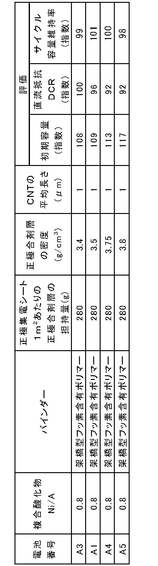
電池A1,A3~A5のいずれも、DCRが小さく、初期容量が大きく、優れたサイクル特性が得られた。特に、正極合剤層の密度が3.45g/cm3以上、3.75g/cm3以下の電池A1、A4では、DCRが更に低減され、サイクル特性が更に向上した。
《実施例6~8》
導電剤に平均長さが表3に示す値のCNTを用いた以外、実施例1の電池A1と同様の方法により実施例6~8の電池A6~A8を作製し、評価した。電池A6~A8の評価結果を表3に示す。表3では、電池A1の評価結果も示す。
導電剤に平均長さが表3に示す値のCNTを用いた以外、実施例1の電池A1と同様の方法により実施例6~8の電池A6~A8を作製し、評価した。電池A6~A8の評価結果を表3に示す。表3では、電池A1の評価結果も示す。
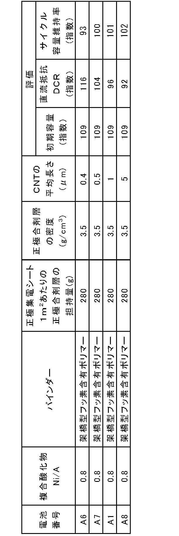
電池A1、A6~A8のいずれも、DCRが小さく、初期容量が大きく、優れたサイクル特性が得られた。特に、CNTの平均長さが0.5μm以上の電池A1、A7~A8では、DCRが更に低減され、サイクル特性が更に向上した。
本開示に係る非水電解質二次電池用正極は、例えば、高容量および優れたサイクル特性が要求される非水電解質二次電池に好適に用いられる。
1 電極群
2 正極リード
3 負極リード
4 電池ケース
5 封口板
6 負極端子
7 ガスケット
8 封栓
2 正極リード
3 負極リード
4 電池ケース
5 封口板
6 負極端子
7 ガスケット
8 封栓
Claims (9)
- 正極集電シートと、前記正極集電シートに担持される正極合剤層と、を備え、
前記正極合剤層は、正極活物質と、バインダーと、導電剤と、を含み、
前記正極活物質は、層状岩塩型の結晶構造を有し、リチウムと、前記リチウム以外の元素Aと、を含む複合酸化物を含み、
前記元素Aは、少なくともニッケルを含み、
前記元素Aに対する前記ニッケルの原子比:Ni/Aは、0.8以上、1.0以下であり、
前記バインダーは、3次元網目構造を有する高分子バインダーを含み、
前記正極集電シートの1m2あたりに担持される前記正極合剤層の質量は、280g以上である、非水電解質二次電池用正極。 - 前記複合酸化物は、一般式:LiaNixCoyM1-x-yO2で表され、
式中、0.97≦a≦1.2、0.8≦x≦1.0および0≦y≦0.2であり、Mは、Mn、Al、B、W、Sr、Mg、Mo、Nb、Ti、SiおよびZrからなる群より選択される少なくとも1種である、請求項1に記載の非水電解質二次電池用正極。 - 前記正極合剤層の密度は、3.45g/cm3以上、3.75g/cm3以下である、請求項1または2に記載の非水電解質二次電池用正極。
- 前記導電剤は、カーボンナノチューブを含み、
前記カーボンナノチューブの平均長さは、0.5μm以上である、
請求項1~3のいずれか1項に記載の非水電解質二次電池用正極。 - 前記高分子バインダーは、フッ素含有ポリマーを含み、
前記フッ素含有ポリマーが架橋されている、請求項1~4のいずれか1項に記載の非水電解質二次電池用正極。 - 前記フッ素含有ポリマーは、架橋性単量体により架橋されている、請求項5に記載の非水電解質二次電池用正極。
- 前記フッ素含有ポリマーは、ポリフッ化ビニリデンおよびフッ化ビニリデンに由来する単位を含む共重合体からなる群より選択される少なくとも1種を含む、請求項5または6に記載の非水電解質二次電池用正極。
- 前記フッ化ビニリデンに由来する単位を含む共重合体は、フッ化ビニリデンと、フッ化ビニリデン以外のフッ素含有単量体との共重合体を含み、
前記フッ化ビニリデン以外のフッ素含有単量体は、6フッ化プロピレン、4フッ化エチレン、3フッ化エチレンおよび3フッ化塩化エチレンからなる群より選択される少なくとも1種を含む、請求項7に記載の非水電解質二次電池用正極。 - 正極と、負極と、非水電解質と、を備え、
前記正極は、請求項1~8のいずれか1項に記載の正極である、非水電解質二次電池。
Priority Applications (4)
| Application Number | Priority Date | Filing Date | Title |
|---|---|---|---|
| JP2022553783A JP7788642B2 (ja) | 2020-09-30 | 2021-09-14 | 非水電解質二次電池用正極および非水電解質二次電池 |
| CN202180066276.8A CN116250100A (zh) | 2020-09-30 | 2021-09-14 | 非水电解质二次电池用正极和非水电解质二次电池 |
| US18/029,003 US20230369561A1 (en) | 2020-09-30 | 2021-09-14 | Positive electrode for nonaqueous electrolyte secondary batteries, and nonaqueous electrolyte secondary battery |
| EP21875193.1A EP4224557A4 (en) | 2020-09-30 | 2021-09-14 | POSITIVE ELECTRODE FOR NON-AQUEOUS ELECTROLYTE SECONDARY BATTERIES AND NON-AQUEOUS ELECTROLYTE SECONDARY BATTERY |
Applications Claiming Priority (2)
| Application Number | Priority Date | Filing Date | Title |
|---|---|---|---|
| JP2020166148 | 2020-09-30 | ||
| JP2020-166148 | 2020-09-30 |
Publications (1)
| Publication Number | Publication Date |
|---|---|
| WO2022070891A1 true WO2022070891A1 (ja) | 2022-04-07 |
Family
ID=80951436
Family Applications (1)
| Application Number | Title | Priority Date | Filing Date |
|---|---|---|---|
| PCT/JP2021/033786 Ceased WO2022070891A1 (ja) | 2020-09-30 | 2021-09-14 | 非水電解質二次電池用正極および非水電解質二次電池 |
Country Status (5)
| Country | Link |
|---|---|
| US (1) | US20230369561A1 (ja) |
| EP (1) | EP4224557A4 (ja) |
| JP (1) | JP7788642B2 (ja) |
| CN (1) | CN116250100A (ja) |
| WO (1) | WO2022070891A1 (ja) |
Cited By (2)
| Publication number | Priority date | Publication date | Assignee | Title |
|---|---|---|---|---|
| WO2024070156A1 (ja) | 2022-09-29 | 2024-04-04 | パナソニックエナジー株式会社 | 非水電解質二次電池用正極および非水電解質二次電池 |
| WO2025074728A1 (ja) * | 2023-10-02 | 2025-04-10 | 株式会社村田製作所 | 正極活物質および二次電池 |
Families Citing this family (1)
| Publication number | Priority date | Publication date | Assignee | Title |
|---|---|---|---|---|
| KR20230058870A (ko) * | 2021-10-25 | 2023-05-03 | 주식회사 엘지에너지솔루션 | 발화억제 구조의 리튬이차전지 |
Citations (4)
| Publication number | Priority date | Publication date | Assignee | Title |
|---|---|---|---|---|
| JPH0831408A (ja) * | 1994-05-13 | 1996-02-02 | Matsushita Electric Ind Co Ltd | 非水電解質リチウム二次電池用正極およびその製造方法 |
| JPH0997611A (ja) * | 1995-09-29 | 1997-04-08 | Toray Ind Inc | 電池用電極および二次電池 |
| WO2011002097A1 (ja) * | 2009-07-03 | 2011-01-06 | ダイキン工業株式会社 | リチウム二次電池の電極合剤用スラリー、該スラリーを用いた電極およびリチウム二次電池 |
| WO2019168035A1 (ja) * | 2018-02-27 | 2019-09-06 | 積水化学工業株式会社 | リチウムイオン二次電池用正極材料、正極活物質層、及びリチウムイオン二次電池 |
Family Cites Families (6)
| Publication number | Priority date | Publication date | Assignee | Title |
|---|---|---|---|---|
| US5609975A (en) * | 1994-05-13 | 1997-03-11 | Matsushita Electric Industrial Co., Ltd. | Positive electrode for non-aqueous electrolyte lithium secondary battery and method of manufacturing the same |
| JP6059019B2 (ja) * | 2013-01-07 | 2017-01-11 | 日立マクセル株式会社 | 非水電解質二次電池 |
| EP3465803B1 (en) | 2016-06-07 | 2021-05-05 | Navitas Systems LLC | High loading electrodes |
| CN106340622A (zh) | 2016-09-27 | 2017-01-18 | 南通江海电容器股份有限公司 | 一种高功率高能量化学电源及其制备方法 |
| CN107546379B (zh) * | 2017-08-18 | 2020-02-28 | 宁波致良新能源有限公司 | 磷酸锰铁锂-三元材料复合正极材料及其制备方法 |
| CN112703619A (zh) | 2018-10-03 | 2021-04-23 | 大金工业株式会社 | 正极结构体和二次电池 |
-
2021
- 2021-09-14 JP JP2022553783A patent/JP7788642B2/ja active Active
- 2021-09-14 CN CN202180066276.8A patent/CN116250100A/zh active Pending
- 2021-09-14 EP EP21875193.1A patent/EP4224557A4/en active Pending
- 2021-09-14 WO PCT/JP2021/033786 patent/WO2022070891A1/ja not_active Ceased
- 2021-09-14 US US18/029,003 patent/US20230369561A1/en active Pending
Patent Citations (4)
| Publication number | Priority date | Publication date | Assignee | Title |
|---|---|---|---|---|
| JPH0831408A (ja) * | 1994-05-13 | 1996-02-02 | Matsushita Electric Ind Co Ltd | 非水電解質リチウム二次電池用正極およびその製造方法 |
| JPH0997611A (ja) * | 1995-09-29 | 1997-04-08 | Toray Ind Inc | 電池用電極および二次電池 |
| WO2011002097A1 (ja) * | 2009-07-03 | 2011-01-06 | ダイキン工業株式会社 | リチウム二次電池の電極合剤用スラリー、該スラリーを用いた電極およびリチウム二次電池 |
| WO2019168035A1 (ja) * | 2018-02-27 | 2019-09-06 | 積水化学工業株式会社 | リチウムイオン二次電池用正極材料、正極活物質層、及びリチウムイオン二次電池 |
Non-Patent Citations (2)
| Title |
|---|
| "Topics, Activities of ABRI", FB TECHNICAL NEWS, vol. 11, no. 74, 2018, pages 34 |
| See also references of EP4224557A4 |
Cited By (2)
| Publication number | Priority date | Publication date | Assignee | Title |
|---|---|---|---|---|
| WO2024070156A1 (ja) | 2022-09-29 | 2024-04-04 | パナソニックエナジー株式会社 | 非水電解質二次電池用正極および非水電解質二次電池 |
| WO2025074728A1 (ja) * | 2023-10-02 | 2025-04-10 | 株式会社村田製作所 | 正極活物質および二次電池 |
Also Published As
| Publication number | Publication date |
|---|---|
| CN116250100A (zh) | 2023-06-09 |
| JPWO2022070891A1 (ja) | 2022-04-07 |
| EP4224557A4 (en) | 2024-11-27 |
| EP4224557A1 (en) | 2023-08-09 |
| US20230369561A1 (en) | 2023-11-16 |
| JP7788642B2 (ja) | 2025-12-19 |
Similar Documents
| Publication | Publication Date | Title |
|---|---|---|
| CN107112499B (zh) | 非水电解质二次电池用负极和非水电解质二次电池 | |
| JP7394324B2 (ja) | 非水電解質二次電池 | |
| KR102590425B1 (ko) | 입경이 상이한 흑연 및 실리콘계 소재를 포함하는 음극 및 이를 포함하는 리튬 이차전지 | |
| JP3868231B2 (ja) | 炭素材料、リチウムイオン二次電池用負極およびリチウムイオン二次電池 | |
| JP7738268B2 (ja) | 二次電池用負極及び二次電池 | |
| WO2018179817A1 (ja) | 非水電解質二次電池用負極及び非水電解質二次電池 | |
| WO2018123751A1 (ja) | 非水電解質二次電池 | |
| JP2023520192A (ja) | 二次電池 | |
| JP6750196B2 (ja) | 非水系リチウム電池及びその使用方法 | |
| JP7547627B2 (ja) | リチウム二次電池の製造方法及びこれにより製造されたリチウム二次電池 | |
| JP7788642B2 (ja) | 非水電解質二次電池用正極および非水電解質二次電池 | |
| JP5505480B2 (ja) | リチウムイオン二次電池用負極及びその負極を用いたリチウムイオン二次電池 | |
| CN102097623B (zh) | 锂电池用正极活性材料及其制造方法、正极和锂电池 | |
| WO2020137560A1 (ja) | 非水電解質二次電池 | |
| JP6808948B2 (ja) | 非水系リチウムイオン二次電池用負極、その製法及び非水系リチウムイオン二次電池 | |
| JP2017152259A (ja) | リチウムイオン二次電池及びその回復方法 | |
| CN115039252A (zh) | 非水电解质二次电池用负极和非水电解质二次电池 | |
| JP7727940B2 (ja) | 非水電解質二次電池用負極および非水電解質二次電池 | |
| CN113632261B (zh) | 非水电解质二次电池用负极及非水电解质二次电池 | |
| JP7801670B2 (ja) | 非水電解質二次電池 | |
| CN114303261B (zh) | 非水电解质二次电池 | |
| JP2011119072A (ja) | リチウム二次電池の使用方法 | |
| JP7691257B2 (ja) | リチウムイオン二次電池用電極およびリチウムイオン二次電池 | |
| JP2003331847A (ja) | 非水二次電池および正極塗料製造方法 | |
| US9466837B1 (en) | Battery having negative electrode including amorphous carbon |
Legal Events
| Date | Code | Title | Description |
|---|---|---|---|
| 121 | Ep: the epo has been informed by wipo that ep was designated in this application |
Ref document number: 21875193 Country of ref document: EP Kind code of ref document: A1 |
|
| ENP | Entry into the national phase |
Ref document number: 2022553783 Country of ref document: JP Kind code of ref document: A |
|
| NENP | Non-entry into the national phase |
Ref country code: DE |
|
| ENP | Entry into the national phase |
Ref document number: 2021875193 Country of ref document: EP Effective date: 20230502 |